Large industrial screw compressors for refrigeration …. Schuhmann, R... · pulsations and with...
14
Large industrial screw compressors for refrigeration units Experiences out of operation and maintenance Roland Schuhmann Senior Diagnostic Manager, Engineering & Maintenance, BASF SE Robert Missal Project Leader machinery and plants, KÖTTER Consulting Engineer GmbH&Co.KG Heinrich Ochs Senior Compressors Manager, Engineering & Maintenance, BASF SE Thomas Schmitt Technology Manager, BASF Antwerpen N.V. Abstract Over the time the cooling capacity of refrigeration units has been increased steadily. Therefore also the compressors themselves became larger and larger. Now we are operating oil injected screw compressors with power ratings of 1.5 MW and more. These compressors – and this is typical for all screw compressors – are the source of vibrations. The first part of the presentation describes the vibration measurement procedure at such screw compressor units and the evaluation of the vibration amplitudes according to the VDI 3836. It gives also an overview about the measuring points and some practical hints how to do the vibration analysis. In the next chapter the different sources of dynamic forces are discussed. Out of practical experiences, a correlation between dynamical fluid and mechanical forces and the measured vibration amplitudes together with rotordynamic calculations is presented. Here the influence of the type of foundation is also discussed. In the third part of the presentation failure modes which were found in the last years during maintenance and repair of these compressors are presented and correlated with measured vibration analysis. Out of this the authors are raising the question whether the existing standards for the evaluation of the vibration and with this the reliability of such screw compressor units are still valid.
Transcript of Large industrial screw compressors for refrigeration …. Schuhmann, R... · pulsations and with...

Large industrial screw compressors for refrigeration units
Experiences out of operation and maintenance
Roland Schuhmann Senior Diagnostic Manager, Engineering & Maintenance, BASF SE
Robert Missal Project Leader machinery and plants, KÖTTER Consulting Engineer
GmbH&Co.KG
Heinrich Ochs Senior Compressors Manager, Engineering & Maintenance, BASF SE
Thomas Schmitt Technology Manager, BASF Antwerpen N.V.
Abstract
Over the time the cooling capacity of refrigeration units has been increased steadily.
Therefore also the compressors themselves became larger and larger. Now we are operating
oil injected screw compressors with power ratings of 1.5 MW and more. These compressors
– and this is typical for all screw compressors – are the source of vibrations.
The first part of the presentation describes the vibration measurement procedure at such
screw compressor units and the evaluation of the vibration amplitudes according to the VDI
3836. It gives also an overview about the measuring points and some practical hints how to
do the vibration analysis. In the next chapter the different sources of dynamic forces are
discussed. Out of practical experiences, a correlation between dynamical fluid and
mechanical forces and the measured vibration amplitudes together with rotordynamic
calculations is presented. Here the influence of the type of foundation is also discussed. In
the third part of the presentation failure modes which were found in the last years during
maintenance and repair of these compressors are presented and correlated with measured
vibration analysis. Out of this the authors are raising the question whether the existing
standards for the evaluation of the vibration and with this the reliability of such screw
compressor units are still valid.
Part 1: Vibration measurement procedure for screw compressor units
Vibration measurements are a common tool for the assessment of machine conditions. For
the evaluation of machines it is essential to perform the measurements and analysis on the
basis of standards which are accepted by the parties involved in the project. In Germany the
standard DIN ISO 10816 is a well-established paper which describes the procedure for
vibration measurements and the evaluation of the measured data. Depending on the type of
machine the operator can find guideline values as basis for the decision if the machine is in a
good or bad condition.
The different parts of this standard [1-7] consider different operating and mounting
conditions, different power classes and different functional principles of the diverse
machines.
Although this ISO standard deals with a lot of different types of machines, there are still some
machines which are not represented by this standard. An example for these types of
machines is screw compressors, which run rougher than turbo compressors but not as rough
as reciprocating compressors. In order to give a help to those people who have to perform
such measurements at screw compressors and roots blowers, the German association VDI
initiated a working group with several experts for this kind of machines. As a result of this
working group the VDI standard 3836 “Measurement and evaluation of mechanical vibration
of screw-type compressors and roots blowers, Addition to DIN ISO 10816 - 3” [8] was
published in August 2006. Besides of the measurement position, there are different
frequency ranges described with dedicated values for housing vibrations and relative rotor
vibrations.

Table 1: Recommended limits for housing vibrations as RMS-values of the vibration
velocity in mm/s, VDI 3836 [8]
The frequency ranges are defined as follows:
Frequency range A:
10 Hz to 1,000 Hz (at least the 3rd harmonic of the output frequency is registered)
Frequency range B:
10 Hz to 2.2 times of the rotational frequency
For the evaluation zones in table 1 the following definitions are registered [8]:
Zone I: Compressors whose vibrations fall within this zone are regarded as suitable for
running without restrictions in continuous operation.
Zone II: Compressors in this zone have high vibration values. A check must be made
in each individual case to see whether the measured values are permissible for unlimited
continuous operation taking into account the design and operating conditions of the unit in

question. In general the compressor may, however, be run for a limited time in this state until
a suitable opportunity arises for remedial measures.
Zone III: Compressors whose vibration values fall within this zone are usually shut
down for examination and repair since their vibration values are regarded as so high that
damage could be caused to the machine.
Besides this, there is another standard called EN ISO 10440 - 1 “Petroleum, petrochemical
and natural gas industries - Rotary-type positive-displacement compressors - Part 1: Process
compressors” [9] which deals with vibration measurements at screw compressors. This
standard bases on the API standard 619 [10] and gives vibration limits for dry and oil-flooded
screw compressors. These limits differ from those given by the VDI 3836, so it is very
important that the involved parties determine the standard which has to be used for the
vibration measurements.
Part 2: Sources of dynamic forces and their correlation with measured vibrations
Every user of screw compressors knows that they are noisy, that they have vibrations and
are often the reason for problems at the compressor system like cracks at pipe works small
bore nozzles or problems at the compressor itself like bearing failures or other machine parts
which are wearing. Almost every time the gas pulsation due to the unsteady flow is expected
to be the main source for the vibrations. Fluid dynamical resonances in the pipes can cause
very high pulsation amplitudes and out of this excite the whole system. Also a bad
adjustment of the internal compression ratio to the operation conditions can cause a so
called under- / or over – compression, which leads to high pulsation levels. These
phenomena’s are well known and out of this, in case of troubles at such systems the experts
are mainly focused on fluid dynamical problems and how to solve these. There are a lot of
papers describing case histories of successfully solved vibration problems where the
pulsations and with this the vibration amplitudes could be reduced by installing orifices, multi
hole plates, changing of discharge pipe wall thickness because of a resonance of the natural
frequency of the pipe shell wall with the pocket pass frequency and stiffening small bore
nozzles with additional brackets.
The common strategy to analyse screw compressor systems with high vibrations is to:
- measure and analyse bearing housing and pipe work vibration

- if possible measure the gas pulsations
- do bump tests to identify natural frequencies
- do fluid dynamic calculations to check for resonances
Because the vibration situation can change significantly with the operation conditions of the
compressors, it is necessary to work out a test procedure for the measurements which cover
all the operation conditions to get assessable data’s.
In our case history the described measurements were done consecutively. The results
showed:
- Very high vibration levels at the compressor and at the pipe work up to 40 mm/s rms
and more
- Very high acoustical noise
- Dominant frequencies are pocket pass and multiples
- Pressure pulsations in the discharge pipe of about +/- 0.4 bar
- Pressure pulsation levels and bearing housing vibrations did not correlate
With these first results it was clear that the pressure pulsations could not be the root cause
for the very high vibrations. So other sources of dynamic forces must play a major role in this
case. Possible sources were identified:
- Weak frame with natural frequencies in the near of pocket pass
- Exciting the torsional natural frequency of the rotor system
- Exciting the natural frequency of the compressor rotors
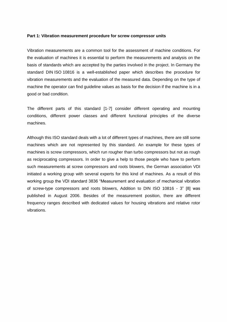
FEM calculations were done for the rotor system and the frame and the measurements were
extended. Additional measurement points at the frame should give a clearer understanding
of the vibration mode shape of the frame. A special sensor was installed to measure the
dynamical torsional stresses at the coupling spacer and eddy current probes (non
contactless) were installed to measure the relative shaft displacement at the male rotor
between the compressor and the coupling hub.
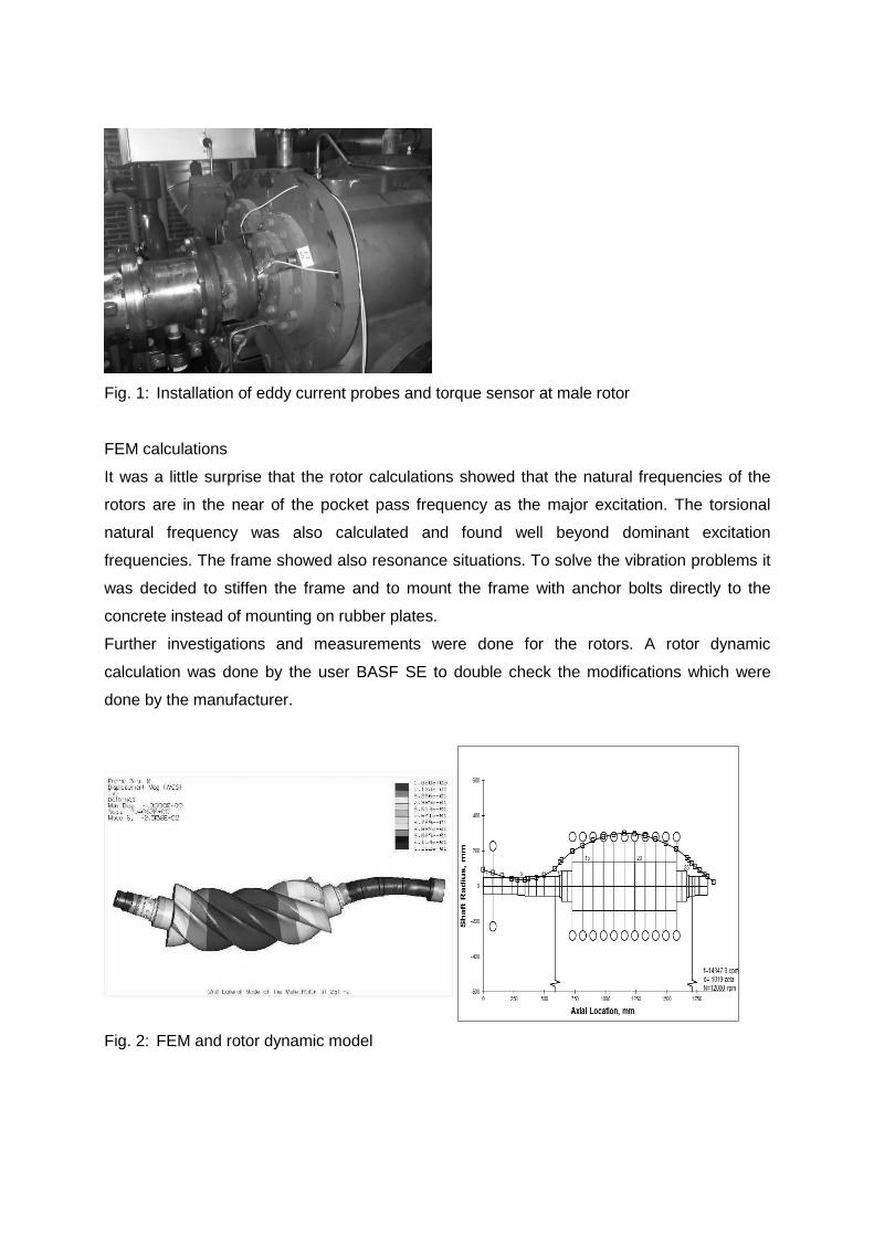
Fig. 1: Installation of eddy current probes and torque sensor at male rotor
FEM calculations
It was a little surprise that the rotor calculations showed that the natural frequencies of the
rotors are in the near of the pocket pass frequency as the major excitation. The torsional
natural frequency was also calculated and found well beyond dominant excitation
frequencies. The frame showed also resonance situations. To solve the vibration problems it
was decided to stiffen the frame and to mount the frame with anchor bolts directly to the
concrete instead of mounting on rubber plates.
Further investigations and measurements were done for the rotors. A rotor dynamic
calculation was done by the user BASF SE to double check the modifications which were
done by the manufacturer.
Fig. 2: FEM and rotor dynamic model

The rotor dynamic model was adjusted to match the calculated Eigen frequency values of the
FEM calculation with the same bearing stiffness.
Now it was possible to apply a dynamic force to match the relative shaft displacements which
were measured during the test with the additional eddy current probes.
After this procedure it was possible to modify the model according the proposed changes
and to run the rotor response calculations.
Fig. 3: Rotor response calculations original and modified rotor – bearing system
The response plots show that with the modifications at the rotor – bearing system the
vibration amplitudes of the rotor could be lowered by a factor of nearly 4 at the pocket pass
frequency.
Measurement with the modified compressor showed also that the relative shaft vibrations
and the bearing housing vibration were lowered by a factor of about 4.
Compressor foundation
During the first test runs of the compressor mounted originally on rubber plates no significant
vibrations at the concrete were noticed. After mounting the frame with anchor bolts together
with the concrete the vibrations travels through the whole concrete base plate with significant
levels of about 1 to 2 mm/s rms at points which are quite far away from the compressor unit.
With these vibration levels bearing failures at stand by machines can be expected.
The reason for this modification was to stiffen significantly the frame and as a consequence
to reduce the vibration amplitudes at the unit. The measurements showed that the difference
of the vibration amplitudes at the compressor itself did not change significantly if the frame is
mounted to the concrete or not.
A short calculation shows that this result was foreseeable.

Assuming that we have an anchor bolt of 16 mm diameter and a length of 300 mm and
expecting vibration amplitude at 200 Hz of 5 mm/s rms. This gives peak displacement
amplitude of 5.6 µm and needed dynamic force acting at the bolt of about 790 N.
The example shows that due to the elasticity of the steel it is nearly impossible to reduce the
vibration amplitudes at these high frequencies.
The case history shows that mechanical, lateral rotor vibration has a significant influence at
the vibration levels of the whole compressor unit and can be a major source. Good
compressor design is needed to reduce this excitation to get a sound compressor unit.
Part 3: Failure modes and their expected root causes
Oil injected screw compressors are used in industrial refrigeration for compression of
ammonia and other refrigerating gases. The schematic diagram of a screw compressor is
shown in Fig. 4
Fig. 4: Screw Compressor with capacity control Slide Stop, Slide Valve [11]
High reliability with continuous operating period of five years, low maintenance costs and a
very wide overall operating range are some expected specific features of oil injected screw
compressors installed in industrial refrigeration for compression of ammonia and other
refrigerating gases from an end user point of view.
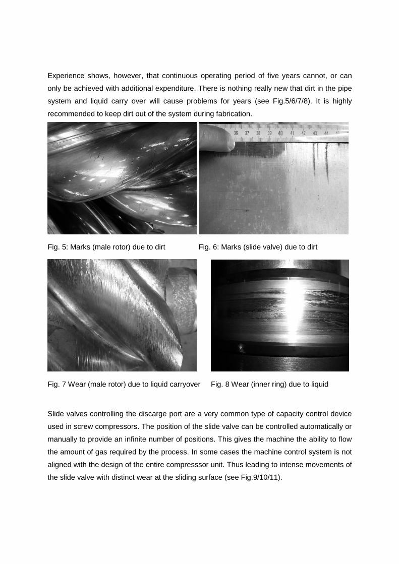
Experience shows, however, that continuous operating period of five years cannot, or can
only be achieved with additional expenditure. There is nothing really new that dirt in the pipe
system and liquid carry over will cause problems for years (see Fig.5/6/7/8). It is highly
recommended to keep dirt out of the system during fabrication.
Fig. 5: Marks (male rotor) due to dirt Fig. 6: Marks (slide valve) due to dirt
Fig. 7 Wear (male rotor) due to liquid carryover Fig. 8 Wear (inner ring) due to liquid
Slide valves controlling the discarge port are a very common type of capacity control device
used in screw compressors. The position of the slide valve can be controlled automatically or
manually to provide an infinite number of positions. This gives the machine the ability to flow
the amount of gas required by the process. In some cases the machine control system is not
aligned with the design of the entire compresssor unit. Thus leading to intense movements of
the slide valve with distinct wear at the sliding surface (see Fig.9/10/11).

Fig. 9: Detail Slide valve scuffing Fig. 10: Slide Valve scuffing
Fig. 11: Discharge housing scuffing
The male and female part of the slide valve is different in the size of their surfaces. In
combination with the internal pressure an additional torsional moment is generated and the
slide valve touches the male and female rotor. Depending on the machine design and the
load condition heavy wear on the slide valve and the rotors appear (see Fig. 13/14/15/16).

Fig. 12: Wear on slide valve due to resulting moment
Fig. 13: Wear on slide valve due to contact with male and female rotor
Fig. 14: Wear on male and female rotor due to contact with slide valve
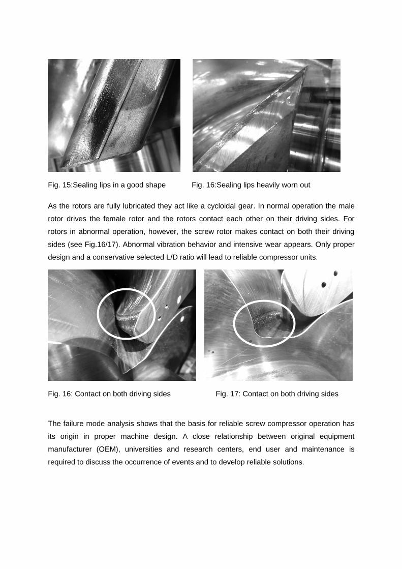
Fig. 15:Sealing lips in a good shape Fig. 16:Sealing lips heavily worn out
As the rotors are fully lubricated they act like a cycloidal gear. In normal operation the male
rotor drives the female rotor and the rotors contact each other on their driving sides. For
rotors in abnormal operation, however, the screw rotor makes contact on both their driving
sides (see Fig.16/17). Abnormal vibration behavior and intensive wear appears. Only proper
design and a conservative selected L/D ratio will lead to reliable compressor units.
Fig. 16: Contact on both driving sides Fig. 17: Contact on both driving sides
The failure mode analysis shows that the basis for reliable screw compressor operation has
its origin in proper machine design. A close relationship between original equipment
manufacturer (OEM), universities and research centers, end user and maintenance is
required to discuss the occurrence of events and to develop reliable solutions.

Part 4: Correlation of failure modes and vibration measurements
The measurements during the test runs at the compressor of the case history in part 2 of this
paper, showed at different operating conditions (slide valve position etc) very different
vibration behaviour. At some conditions the vibration amplitudes and also the noise was very
unstable while at other conditions the trend shows a stable situation. The absolute vibration
level is therefore nearly constant.
Fig. 17: Trend overall vibration amplitudes black= unstable; grey= stable
If these unstable situations are the root cause for the wear, rotor and bearing failures and the
reduced lifetime of compressors, the question raises whether not only the vibration amplitude
but also the stability of the values over time during a constant operation condition should be
taken into account to qualify a compressor system.
Also as shown in the part 3 of the presentation wear at the slide valve and the rotors are
affected by the compressor control system. Permanent adjusting of the slide valve due to a
sensitive control algorithm has a negative effect for these parts. Out of this the question from
the user side comes up, not only to design the control algorithms for best efficiency but also
for longer lifetime and reliability of the compressor.
Slide stop
Slide valve
Direct rms

References
[1] ISO 10816 - Part 1
1995-12
Mechanical vibration - Evaluation of machine vibration by
measurements on non-rotating parts - Part 1: General guidelines
[2] ISO 10816 - Part 2
2009-10
Mechanical vibration - Evaluation of machine vibration by
measurements on non-rotating parts - Part 2: Large land-based
steam turbine generator sets in excess of 50 MW
[3] ISO 10816 - Part 3
2009-02
Mechanical vibration - Evaluation of machine vibration by
measurements on non-rotating parts - Part 3: Industrial
machines with nominal power above 15 kW and nominal speeds
between 120 r/min and 15000 r/min when measured in situ
[4] ISO 10816 - Part 4
2009-10
Mechanical vibration - Evaluation of machine vibration by
measurements on non-rotating parts - Part 4: Gas turbine sets
with fluid-film bearings
[5] ISO 10816 - Part 5
2000-04
Mechanical vibration - Evaluation of machine vibration by
measurements on non-rotating parts - Part 5: Machine sets in
hydraulic power generation and pumping plants
[6] ISO 10816 - Part 7
2009-02
Mechanical vibration - Evaluation of machine vibration by
measurements on non-rotating parts - Part 7: Rotordynamic
pumps for industrial applications, including measurements on
rotating shafts
[7] ISO 10816 - Part 8
2014-05
Mechanical vibration - Evaluation of machine vibration by
measurements on non-rotating parts - Part 8: Reciprocating
compressor systems
[8] VDI3836
2012-02
Measurement and evaluation of mechanical vibration of screw-
type compressors and roots blowers, Addition to DIN ISO 10816
- Part 3
[9] EN ISO 10440 - Part 1
2008-09
Petroleum, petrochemical and natural gas industries - Rotary-
type positive displacement compressors - Part 1: Process
compressors
[10] API Standard 619
2010-12
Rotary-type positive displacement compressors for petroleum,
petrochemical and natural gas industries, 5th edition
[11] Training information York by Johnson Controls, www.johnsoncontrols.com