Large and High Voltage Motors - teco.com.t Motor products and publications LARGE AND HIGH VOLTAGE...
12
ENGINEERING THE FUTURE Large and High Voltage Motors Bespoke construction to your needs
Transcript of Large and High Voltage Motors - teco.com.t Motor products and publications LARGE AND HIGH VOLTAGE...

ENGINEERING THE FUTURE
Large and HighVoltage MotorsBespoke construction to your needs
2
TE
CO
Mo
tor
pro
du
cts
and
p
ub
licat
ion
s
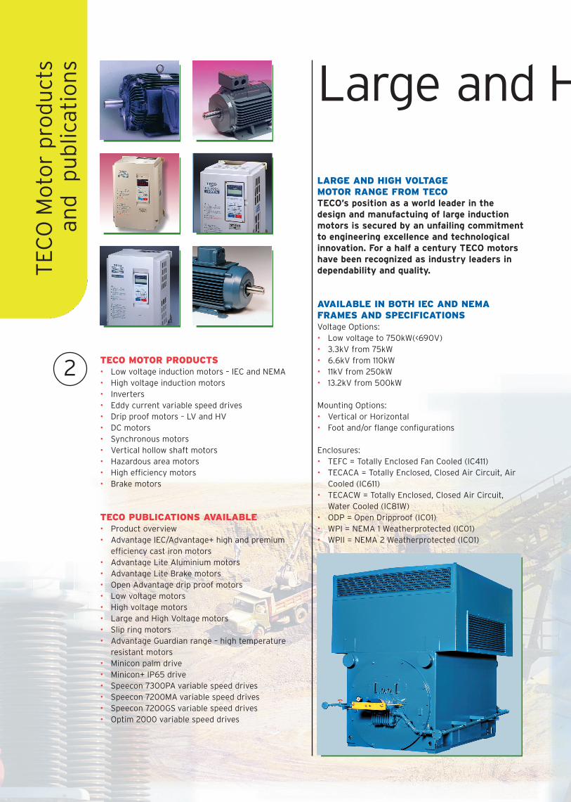
LARGE AND HIGH VOLTAGE MOTOR RANGE FROM TECOTECO’s position as a world leader in thedesign and manufactuing of large inductionmotors is secured by an unfailing commitmentto engineering excellence and technologicalinnovation. For a half a century TECO motorshave been recognized as industry leaders independability and quality.
AVAILABLE IN BOTH IEC AND NEMAFRAMES AND SPECIFICATIONSVoltage Options:• Low voltage to 750kW(<690V)• 3.3kV from 75kW• 6.6kV from 110kW • 11kV from 250kW• 13.2kV from 500kW
Mounting Options:• Vertical or Horizontal• Foot and/or flange configurations
Enclosures:• TEFC = Totally Enclosed Fan Cooled (IC411)• TECACA = Totally Enclosed, Closed Air Circuit, Air
Cooled (IC611)• TECACW = Totally Enclosed, Closed Air Circuit,
Water Cooled (IC81W)• ODP = Open Dripproof (IC01)• WPI = NEMA 1 Weatherprotected (IC01)• WPII = NEMA 2 Weatherprotected (IC01)
TECO MOTOR PRODUCTS• Low voltage induction motors – IEC and NEMA• High voltage induction motors• Inverters• Eddy current variable speed drives• Drip proof motors – LV and HV• DC motors• Synchronous motors• Vertical hollow shaft motors• Hazardous area motors• High efficiency motors• Brake motors
TECO PUBLICATIONS AVAILABLE• Product overview• Advantage IEC/Advantage+ high and premium
efficiency cast iron motors• Advantage Lite Aluminium motors• Advantage Lite Brake motors• Open Advantage drip proof motors• Low voltage motors • High voltage motors• Large and High Voltage motors• Slip ring motors• Advantage Guardian range – high temperature
resistant motors• Minicon palm drive• Minicon+ IP65 drive• Speecon 7300PA variable speed drives• Speecon 7200MA variable speed drives• Speecon 7200GS variable speed drives• Optim 2000 variable speed drives
Large and H
3
Intro
du
ction
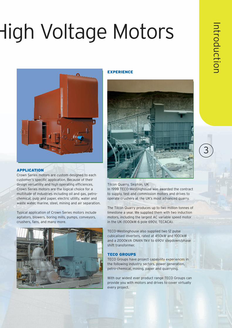
APPLICATIONCrown Series motors are custom designed to eachcustomer’s specific application. Because of theirdesign versatility and high operating efficiences,Crown Series motors are the logical choice for amultitude of industries including oil and gas, petro-chemical, pulp and paper, electric utility, water andwaste water, marine, steel, mining and air separation.
Typical application of Crown Series motors includeagitators, blowers, boring mills, pumps, conveyors,crushers, fans, and many more.
High Voltage Motors
EXPERIENCE
Tilcon Quarry, Skipton, UKIn 1999 TECO-Westinghouse was awarded the contractto supply, test and commission motors and drives tooperate crushers at the UK’s most advanced quarry.
The Tilcon Quarry produces up to two million tonnes oflimestone a year. We supplied them with two inductionmotors, including the largest AC variable speed motorin the UK (1000kW 6 pole 690V, TECACA).
TECO-Westinghouse also supplied two 12 pulsecubicalised inverters, rated at 450kW and 1000kWand a 2000kVA ONAN 11kV to 690V stepdown/phaseshift transformer.
TECO GROUPSTECO Groups have project capability experiences inthe following industry sectors, power generation,petro-chemical, mining, paper and quarrying.
With our widest ever product range TECO Groups canprovide you with motors and drives to cover virtuallyevery project.
4
Fram
e an
d R
oto
r
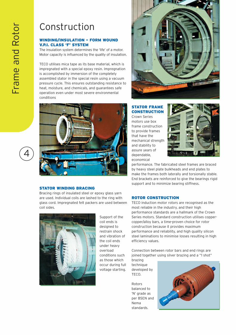
WINDING/INSULATION – FORM WOUNDV.P.I. CLASS ‘F’ SYSTEMThe insulation system determines the ‘life’ of a motor.Motor capacity is influenced by the quality of insulation.
TECO utilises mica tape as its base material, which isimpregnated with a special epoxy resin. Impregnationis accomplished by immersion of the completelyassembled stator in the special resin using a vacuumpressure cycle. This ensures outstanding resistance toheat, moisture, and chemicals, and guarantees safeoperation even under most severe environmentalconditions
STATOR WINDING BRACINGBracing rings of insulated steel or epoxy glass yarnare used. Individual coils are lashed to the ring withglass cord. Impregnated felt packers are used betweencoil sides.
Support of thecoil ends isdesigned torestrain shockand vibration ofthe coil endsunder heavyoverloadconditions suchas those whichoccur during fullvoltage starting.
STATOR FRAMECONSTRUCTIONCrown Seriesmotors use boxframe constructionto provide framesthat have themechanical strengthand stability toassure years ofdependable,economicalperformance. The fabricated steel frames are bracedby heavy steel plate bulkheads and end plates tomake the frames both laterally and torsionally stable.End brackets are reinforced to give the bearings rigidsupport and to minimize bearing stiffness.
ROTOR CONSTRUCTIONTECO induction motor rotors are recognised as themost reliable in the industry, and their highperformance standards are a hallmark of the CrownSeries motors. Standard construction utilises copper-copper/alloy bars, a time-proven choice for rotorconstruction because it provides maximumperformance and reliability, and high quality siliconsteel laminations to minimise losses resulting in highefficiency values.
Connection between rotor bars and end rings arejoined together using silver brazing and a “1 shot”brazingtechniquedeveloped byTECO.
Rotorsbalanced to‘N’ grade asper BSEN andNemastandards.
Construction
5
Bearin
gs an
d Testin
g
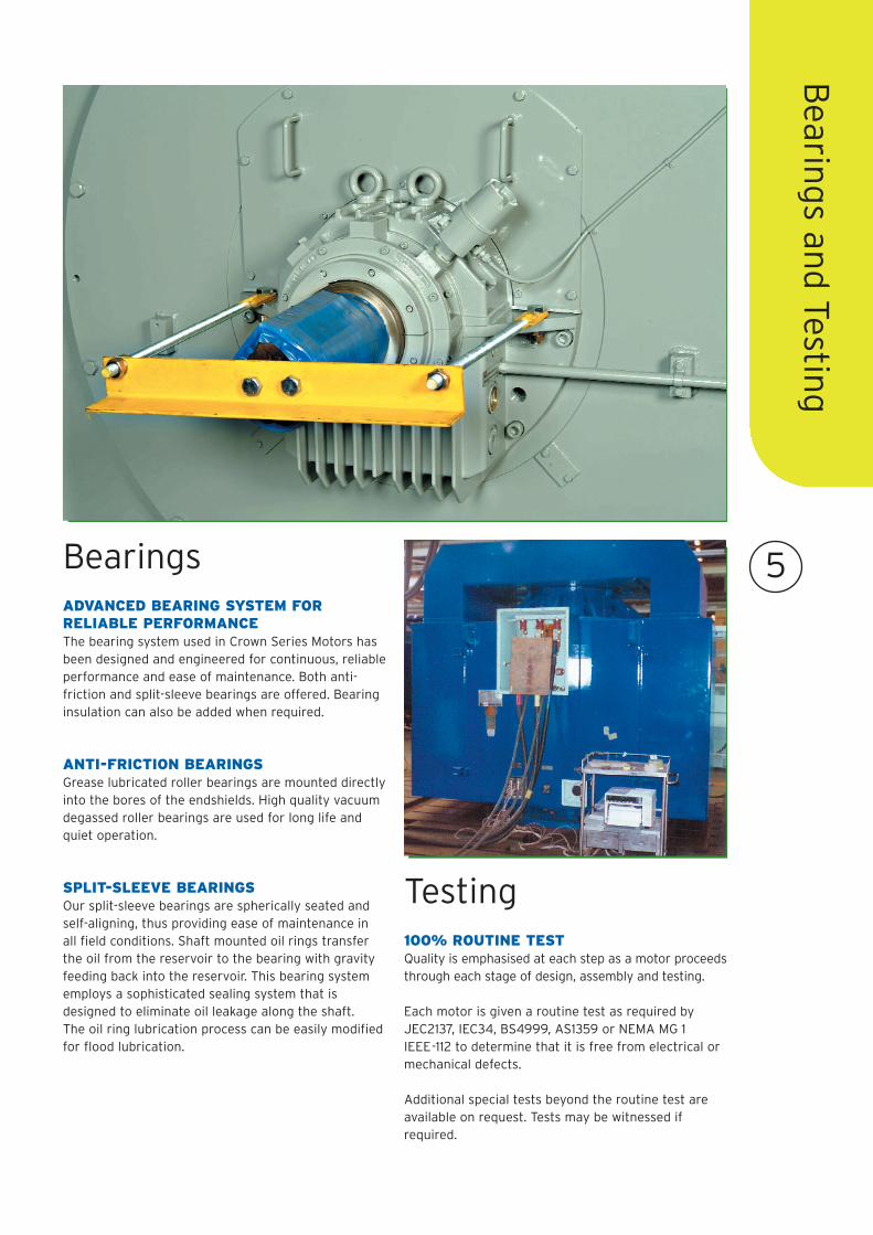
ADVANCED BEARING SYSTEM FORRELIABLE PERFORMANCEThe bearing system used in Crown Series Motors hasbeen designed and engineered for continuous, reliableperformance and ease of maintenance. Both anti-friction and split-sleeve bearings are offered. Bearinginsulation can also be added when required.
ANTI-FRICTION BEARINGSGrease lubricated roller bearings are mounted directlyinto the bores of the endshields. High quality vacuumdegassed roller bearings are used for long life andquiet operation.
SPLIT-SLEEVE BEARINGSOur split-sleeve bearings are spherically seated andself-aligning, thus providing ease of maintenance in all field conditions. Shaft mounted oil rings transferthe oil from the reservoir to the bearing with gravityfeeding back into the reservoir. This bearing systememploys a sophisticated sealing system that isdesigned to eliminate oil leakage along the shaft. The oil ring lubrication process can be easily modifiedfor flood lubrication.
100% ROUTINE TEST Quality is emphasised at each step as a motor proceedsthrough each stage of design, assembly and testing.
Each motor is given a routine test as required byJEC2137, IEC34, BS4999, AS1359 or NEMA MG 1IEEE-112 to determine that it is free from electrical ormechanical defects.
Additional special tests beyond the routine test areavailable on request. Tests may be witnessed ifrequired.
Bearings
Testing
6
Dim
ensi
on
s
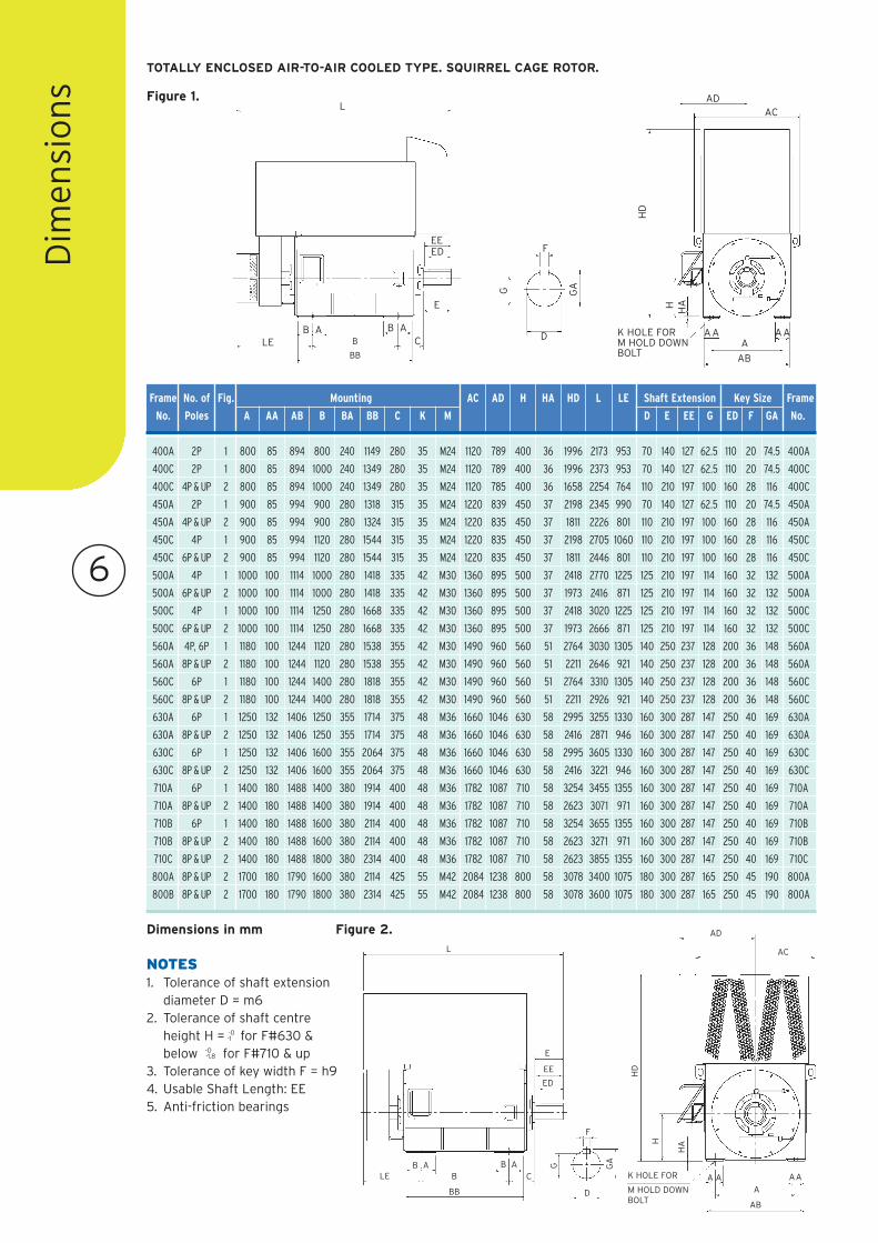
400A 2P 1 800 85 894 800 240 1149 280 35 M24 1120 789 400 36 1996 2173 953 70 140 127 62.5 110 20 74.5 400A
400C 2P 1 800 85 894 1000 240 1349 280 35 M24 1120 789 400 36 1996 2373 953 70 140 127 62.5 110 20 74.5 400C
400C 4P & UP 2 800 85 894 1000 240 1349 280 35 M24 1120 785 400 36 1658 2254 764 110 210 197 100 160 28 116 400C
450A 2P 1 900 85 994 900 280 1318 315 35 M24 1220 839 450 37 2198 2345 990 70 140 127 62.5 110 20 74.5 450A
450A 4P & UP 2 900 85 994 900 280 1324 315 35 M24 1220 835 450 37 1811 2226 801 110 210 197 100 160 28 116 450A
450C 4P 1 900 85 994 1120 280 1544 315 35 M24 1220 835 450 37 2198 2705 1060 110 210 197 100 160 28 116 450C
450C 6P & UP 2 900 85 994 1120 280 1544 315 35 M24 1220 835 450 37 1811 2446 801 110 210 197 100 160 28 116 450C
500A 4P 1 1000 100 1114 1000 280 1418 335 42 M30 1360 895 500 37 2418 2770 1225 125 210 197 114 160 32 132 500A
500A 6P & UP 2 1000 100 1114 1000 280 1418 335 42 M30 1360 895 500 37 1973 2416 871 125 210 197 114 160 32 132 500A
500C 4P 1 1000 100 1114 1250 280 1668 335 42 M30 1360 895 500 37 2418 3020 1225 125 210 197 114 160 32 132 500C
500C 6P & UP 2 1000 100 1114 1250 280 1668 335 42 M30 1360 895 500 37 1973 2666 871 125 210 197 114 160 32 132 500C
560A 4P, 6P 1 1180 100 1244 1120 280 1538 355 42 M30 1490 960 560 51 2764 3030 1305 140 250 237 128 200 36 148 560A
560A 8P & UP 2 1180 100 1244 1120 280 1538 355 42 M30 1490 960 560 51 2211 2646 921 140 250 237 128 200 36 148 560A
560C 6P 1 1180 100 1244 1400 280 1818 355 42 M30 1490 960 560 51 2764 3310 1305 140 250 237 128 200 36 148 560C
560C 8P & UP 2 1180 100 1244 1400 280 1818 355 42 M30 1490 960 560 51 2211 2926 921 140 250 237 128 200 36 148 560C
630A 6P 1 1250 132 1406 1250 355 1714 375 48 M36 1660 1046 630 58 2995 3255 1330 160 300 287 147 250 40 169 630A
630A 8P & UP 2 1250 132 1406 1250 355 1714 375 48 M36 1660 1046 630 58 2416 2871 946 160 300 287 147 250 40 169 630A
630C 6P 1 1250 132 1406 1600 355 2064 375 48 M36 1660 1046 630 58 2995 3605 1330 160 300 287 147 250 40 169 630C
630C 8P & UP 2 1250 132 1406 1600 355 2064 375 48 M36 1660 1046 630 58 2416 3221 946 160 300 287 147 250 40 169 630C
710A 6P 1 1400 180 1488 1400 380 1914 400 48 M36 1782 1087 710 58 3254 3455 1355 160 300 287 147 250 40 169 710A
710A 8P & UP 2 1400 180 1488 1400 380 1914 400 48 M36 1782 1087 710 58 2623 3071 971 160 300 287 147 250 40 169 710A
710B 6P 1 1400 180 1488 1600 380 2114 400 48 M36 1782 1087 710 58 3254 3655 1355 160 300 287 147 250 40 169 710B
710B 8P & UP 2 1400 180 1488 1600 380 2114 400 48 M36 1782 1087 710 58 2623 3271 971 160 300 287 147 250 40 169 710B
710C 8P & UP 2 1400 180 1488 1800 380 2314 400 48 M36 1782 1087 710 58 2623 3855 1355 160 300 287 147 250 40 169 710C
800A 8P & UP 2 1700 180 1790 1600 380 2114 425 55 M42 2084 1238 800 58 3078 3400 1075 180 300 287 165 250 45 190 800A
800B 8P & UP 2 1700 180 1790 1800 380 2314 425 55 M42 2084 1238 800 58 3078 3600 1075 180 300 287 165 250 45 190 800A
Frame No. of Fig. Mounting AC AD H HA HD L LE Shaft Extension Key Size Frame
No. Poles A AA AB B BA BB C K M D E EE G ED F GA No.
Figure 1.
Figure 2.
NOTES1. Tolerance of shaft extension
diameter D = m62. Tolerance of shaft centre
height H = -0-1 for F#630 &
below -0-1.8 for F#710 & up
3. Tolerance of key width F = h94. Usable Shaft Length: EE5. Anti-friction bearings
Dimensions in mm
TOTALLY ENCLOSED AIR-TO-AIR COOLED TYPE. SQUIRREL CAGE ROTOR.
L
EDEE
E
B AB AB
BB
LE
HD
H HA
AAA
AB
K HOLE FORM HOLD DOWNBOLT
ADAC
F
D
GAG
HD
H
HA
A AA
AB
AAK HOLE FOR
M HOLD DOWNBOLT
L
ED
EE
E
B AB AB
BB
LE C
CAA
AD
AC
F
D
GAG
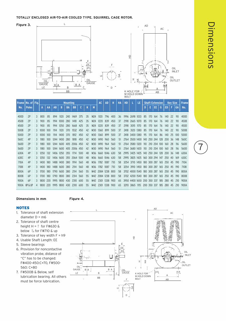
Figure 4.
F
D
GAG
L
EDEE
E
B AB A
B
BB
LE
OILGAUGE OIL
GAUGE
OILOUTLET
OILINLET
K HOLE FORM HOLD DOWNBOLT
H HA
A
AB
AA
AD
AC
HD
A AC
7
Dim
ensio
ns
Figure 3.
NOTES1. Tolerance of shaft extension
diameter D = m62. Tolerance of shaft centre
height H = -0-1 for F#630 &
below -0-1.8 for F#710 & up
3. Tolerance of key width F = h94. Usable Shaft Length: EE5. Sleeve bearings6. Provision for noncontactive
vibration probe, distance of“C” has to be changed:F#400-450:C+70, F#500-560: C+80
7. F#500B & Below, selflubrication bearing. All othersmust be force lubrication.
Dimensions in mm
400D 2P 3 800 85 894 1120 240 1469 375 35 M24 1120 796 400 36 1996 2698 1033 85 170 164 76 140 22 90 400D
450B 2P 3 900 85 994 1000 280 1418 425 35 M24 1220 839 450 37 2198 2665 1070 85 170 164 76 140 22 90 450B
450D 2P 3 900 85 994 1250 280 1668 425 35 M24 1220 839 450 37 2198 3015 1170 85 170 164 76 140 22 90 450D
500B 2P 3 1000 100 1114 1120 370 1532 450 42 M30 1360 899 500 37 2418 3120 1380 85 170 164 76 140 22 90 500B
500D 2P 3 1000 100 1114 1400 370 1812 450 42 M30 1360 899 500 37 2418 3400 1380 95 170 164 86 140 25 100 500D
560C 4P 3 1180 100 1244 1400 280 1818 450 42 M30 1490 960 560 51 2764 3500 1400 140 250 244 128 200 36 148 560C
560D 2P 3 1180 100 1244 1600 405 2006 450 42 M30 1490 964 560 51 2764 3580 1320 110 210 204 100 160 28 116 560D
560D 2P 3 1180 100 1244 1600 405 2006 450 42 M30 1490 964 560 51 2764 3680 1420 110 210 204 100 160 28 116 560D
630A 4P 3 1250 132 1406 1250 355 1714 500 48 M36 1660 1046 630 58 2995 3425 1425 140 250 244 128 200 36 148 630A
630C 4P 3 1250 132 1406 1600 355 2064 500 48 M36 1660 1046 630 58 2995 3825 1425 160 300 294 147 250 40 169 630C
710A 4P 3 1400 180 1488 1400 380 1914 560 48 M36 1782 1087 710 58 3254 3710 1450 180 300 287 165 250 45 190 710A
710B 4P 3 1400 180 1488 1600 380 2114 560 48 M36 1782 1087 710 58 3254 3910 1450 180 300 287 165 250 45 190 710B
800A 6P 3 1700 180 1790 1600 380 2114 560 55 M42 2084 1238 800 58 3702 4000 1540 180 300 287 165 250 45 190 800A
800B 6P 3 1700 180 1790 1800 380 2314 560 55 M42 2084 1238 800 58 3702 4200 1540 180 300 287 165 250 45 190 800B
900A 6P 3 1800 220 1995 1800 430 2310 600 55 M42 2301 1338 900 65 3950 4400 1650 200 350 337 185 280 45 210 900A
900A 8P & UP 4 1800 220 1995 1800 430 2310 600 55 M42 2301 1338 900 65 3293 3865 1115 200 350 337 185 280 45 210 900A
Frame No. of Fig. Mounting AC AD H HA HD L LE Shaft Extension Key Size Frame
No. Poles A AA AB B BA BB C K M D E EE G ED F GA No.
TOTALLY ENCLOSED AIR-TO-AIR COOLED TYPE. SQUIRREL CAGE ROTOR.
L
EDEEE
B AB AB
BB
LE
OILGAUGE
OILGAUGE
OILOUTLET
OILINLET
K HOLE FORM HOLD DOWNBOLT
H
HA
AAB
AA AA
ADAC
HD
F
D
GAG
C
8
Dim
ensi
on
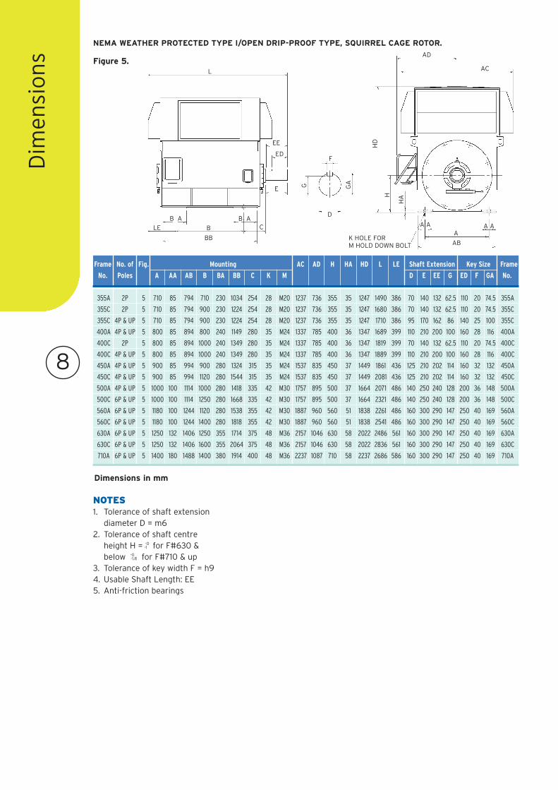
s Figure 5.
355A 2P 5 710 85 794 710 230 1034 254 28 M20 1237 736 355 35 1247 1490 386 70 140 132 62.5 110 20 74.5 355A
355C 2P 5 710 85 794 900 230 1224 254 28 M20 1237 736 355 35 1247 1680 386 70 140 132 62.5 110 20 74.5 355C
355C 4P & UP 5 710 85 794 900 230 1224 254 28 M20 1237 736 355 35 1247 1710 386 95 170 162 86 140 25 100 355C
400A 4P & UP 5 800 85 894 800 240 1149 280 35 M24 1337 785 400 36 1347 1689 399 110 210 200 100 160 28 116 400A
400C 2P 5 800 85 894 1000 240 1349 280 35 M24 1337 785 400 36 1347 1819 399 70 140 132 62.5 110 20 74.5 400C
400C 4P & UP 5 800 85 894 1000 240 1349 280 35 M24 1337 785 400 36 1347 1889 399 110 210 200 100 160 28 116 400C
450A 4P & UP 5 900 85 994 900 280 1324 315 35 M24 1537 835 450 37 1449 1861 436 125 210 202 114 160 32 132 450A
450C 4P & UP 5 900 85 994 1120 280 1544 315 35 M24 1537 835 450 37 1449 2081 436 125 210 202 114 160 32 132 450C
500A 4P & UP 5 1000 100 1114 1000 280 1418 335 42 M30 1757 895 500 37 1664 2071 486 140 250 240 128 200 36 148 500A
500C 6P & UP 5 1000 100 1114 1250 280 1668 335 42 M30 1757 895 500 37 1664 2321 486 140 250 240 128 200 36 148 500C
560A 6P & UP 5 1180 100 1244 1120 280 1538 355 42 M30 1887 960 560 51 1838 2261 486 160 300 290 147 250 40 169 560A
560C 6P & UP 5 1180 100 1244 1400 280 1818 355 42 M30 1887 960 560 51 1838 2541 486 160 300 290 147 250 40 169 560C
630A 6P & UP 5 1250 132 1406 1250 355 1714 375 48 M36 2157 1046 630 58 2022 2486 561 160 300 290 147 250 40 169 630A
630C 6P & UP 5 1250 132 1406 1600 355 2064 375 48 M36 2157 1046 630 58 2022 2836 561 160 300 290 147 250 40 169 630C
710A 6P & UP 5 1400 180 1488 1400 380 1914 400 48 M36 2237 1087 710 58 2237 2686 586 160 300 290 147 250 40 169 710A
Frame No. of Fig. Mounting AC AD H HA HD L LE Shaft Extension Key Size Frame
No. Poles A AA AB B BA BB C K M D E EE G ED F GA No.
NEMA WEATHER PROTECTED TYPE I/OPEN DRIP-PROOF TYPE, SQUIRREL CAGE ROTOR.
NOTES1. Tolerance of shaft extension
diameter D = m62. Tolerance of shaft centre
height H = -0-1 for F#630 &
below -0-1.8 for F#710 & up
3. Tolerance of key width F = h94. Usable Shaft Length: EE5. Anti-friction bearings
F
D
GAG
HD
H
HA
A AA
AB
A A
K HOLE FORM HOLD DOWN BOLT
AD
ACL
ED
EE
E
B AB A
B
BB
LE C
Dimensions in mm
9
Dim
ensio
ns
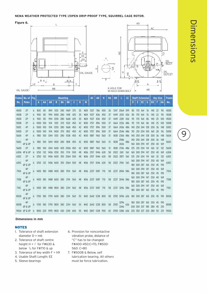
Figure 6.
400D 2P 6 800 85 894 1120 240 1469 375 35 M24 1337 786 400 36 1347 2064 399 85 170 164 76 140 22 90 400D
450B 2P 6 900 85 994 1000 280 1418 425 35 M24 1537 836 450 37 1449 2031 436 85 170 164 76 140 22 90 450B
450D 2P 6 900 85 994 1250 280 1668 425 35 M24 1537 836 450 37 1449 2281 436 95 170 164 86 140 25 100 450D
500B 2P 6 1000 100 1114 1120 370 1532 450 42 M30 1757 896 500 37 1664 2226 486 95 170 164 86 140 25 100 500B
500C 4P 6 1000 100 1114 1250 280 1668 450 42 M30 1757 896 500 37 1664 2436 486 140 250 244 128 200 36 148 500C
500D 2P 6 1000 100 1114 1400 370 1812 450 42 M30 1757 896 500 37 1664 2546 486 110 210 204 100 160 28 116 500D
560A 4P 6 1180 100 1244 1120 280 1538 450 42 M30 1887 960 560 51 1838 2306 486 140 250 244 128 200 36 148 560A
560C4P
6 1180 100 1244 1400 280 1818 450 42 M30 1887 560 51 18382586
486140 250 244 128 200 36 148
560C6P & UP
9602636 160 300 294 147 250 40 169
560D 2P 6 1180 100 1244 1600 405 2006 450 42 M30 1887 960 560 51 1838 2746 486 125 210 204 114 160 32 132 560D
630A 4P & UP 6 1250 132 1406 1250 355 1714 500 48 M36 2157 1046 630 58 2022 2611 561 160 300 294 147 250 40 169 630A
630C 2P 6 1250 132 1406 1600 355 2064 500 48 M36 2157 1046 630 58 2022 2871 561 125 210 204 114 160 32 132 630C
630C4P
6 1250 132 1406 1600 355 2064 500 48 M36 2157 1046 630 58 2022 2961 561160 300 294 147 250 40 169
630C6P & UP 180 300 287 165 250 45 190
710A4P
6 1400 180 1488 1400 380 1914 560 48 M36 2237 1087 710 58 2237 2846 586160 300 294 147 250 40 169
710A6P & UP 180 300 287 165 250 45 190
710B4P
6 1400 180 1488 1600 380 2114 560 48 M36 2237 1087 710 58 2237 3046 586160 300 294 147 250 40 169
710B6P & UP 180 300 287 165 250 45 190
710C4P
6 1400 180 1488 1800 380 2314 560 48 M36 2237 1087 710 58 2237 3246 586160 300 294 147 250 40 169
710C6P & UP 180 300 287 165 250 45 190
800A4P
6 1700 180 1790 1600 380 2114 560 55 M42 2642 1238 800 58 2592 3096 636 180 300 287 165 250 45 190 800A6P & UP
800B4P
6 1700 180 1790 1800 380 2314 560 55 M42 2642 1238 800 58 25923296
636180 300 287 165 250 45 190
800B6P & UP 3346 200 350 337 185 280 45 210
900A 6P & UP 6 1800 220 1995 1800 430 2310 600 55 M42 2847 1338 900 65 2900 3386 636 220 350 337 203 280 50 231 900A
Frame No. of Fig. Mounting AC AD H HA HD L LE Shaft Extension Key Size Frame
No. Poles A AA AB B BA BB C K M D E EE G ED F GA No.
NEMA WEATHER PROTECTED TYPE I/OPEN DRIP-PROOF TYPE, SQUIRREL CAGE ROTOR.
F
D
GAG
HD
H
HA
A A
A
AB
A A
K HOLE FORM HOLD DOWN BOLT
AD
AC
L
ED
EE
OIL GAUGE
B AB A
B
BB
LE C
E
OIL GAUGE
OIL INLET
OIL OUTLET
NOTES1. Tolerance of shaft extension
diameter D = m62. Tolerance of shaft centre
height H = -0-1 for F#630 &
below -0-1.8 for F#710 & up
3. Tolerance of key width F = h94. Usable Shaft Length: EE5. Sleeve bearings
6. Provision for noncontactivevibration probe, distance of“C” has to be changed:F#400-450:C+70, F#500-560: C+80
7. F#500B & Below, selflubrication bearing. All othersmust be force lubrication.
Dimensions in mm
10
Dim
ensi
on
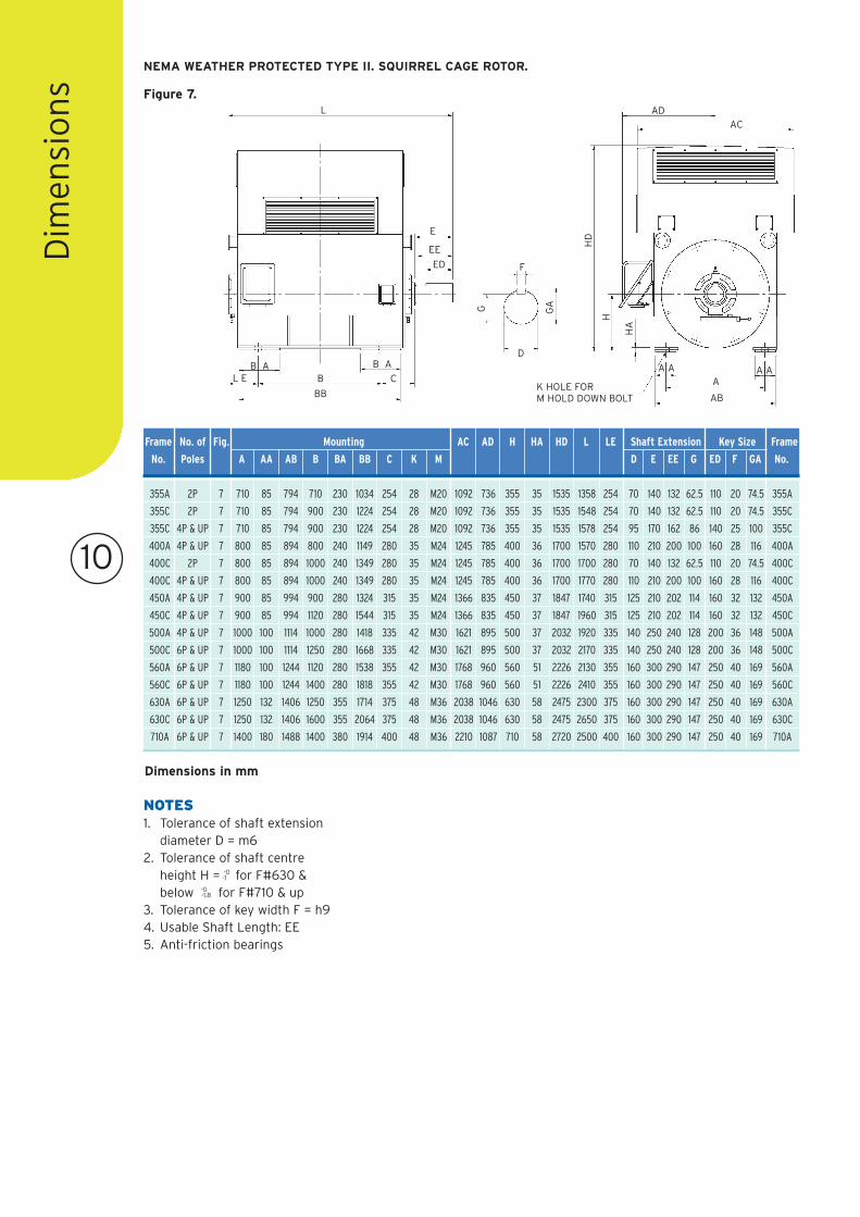
s Figure 7.
355A 2P 7 710 85 794 710 230 1034 254 28 M20 1092 736 355 35 1535 1358 254 70 140 132 62.5 110 20 74.5 355A
355C 2P 7 710 85 794 900 230 1224 254 28 M20 1092 736 355 35 1535 1548 254 70 140 132 62.5 110 20 74.5 355C
355C 4P & UP 7 710 85 794 900 230 1224 254 28 M20 1092 736 355 35 1535 1578 254 95 170 162 86 140 25 100 355C
400A 4P & UP 7 800 85 894 800 240 1149 280 35 M24 1245 785 400 36 1700 1570 280 110 210 200 100 160 28 116 400A
400C 2P 7 800 85 894 1000 240 1349 280 35 M24 1245 785 400 36 1700 1700 280 70 140 132 62.5 110 20 74.5 400C
400C 4P & UP 7 800 85 894 1000 240 1349 280 35 M24 1245 785 400 36 1700 1770 280 110 210 200 100 160 28 116 400C
450A 4P & UP 7 900 85 994 900 280 1324 315 35 M24 1366 835 450 37 1847 1740 315 125 210 202 114 160 32 132 450A
450C 4P & UP 7 900 85 994 1120 280 1544 315 35 M24 1366 835 450 37 1847 1960 315 125 210 202 114 160 32 132 450C
500A 4P & UP 7 1000 100 1114 1000 280 1418 335 42 M30 1621 895 500 37 2032 1920 335 140 250 240 128 200 36 148 500A
500C 6P & UP 7 1000 100 1114 1250 280 1668 335 42 M30 1621 895 500 37 2032 2170 335 140 250 240 128 200 36 148 500C
560A 6P & UP 7 1180 100 1244 1120 280 1538 355 42 M30 1768 960 560 51 2226 2130 355 160 300 290 147 250 40 169 560A
560C 6P & UP 7 1180 100 1244 1400 280 1818 355 42 M30 1768 960 560 51 2226 2410 355 160 300 290 147 250 40 169 560C
630A 6P & UP 7 1250 132 1406 1250 355 1714 375 48 M36 2038 1046 630 58 2475 2300 375 160 300 290 147 250 40 169 630A
630C 6P & UP 7 1250 132 1406 1600 355 2064 375 48 M36 2038 1046 630 58 2475 2650 375 160 300 290 147 250 40 169 630C
710A 6P & UP 7 1400 180 1488 1400 380 1914 400 48 M36 2210 1087 710 58 2720 2500 400 160 300 290 147 250 40 169 710A
Frame No. of Fig. Mounting AC AD H HA HD L LE Shaft Extension Key Size Frame
No. Poles A AA AB B BA BB C K M D E EE G ED F GA No.
NEMA WEATHER PROTECTED TYPE II. SQUIRREL CAGE ROTOR.
NOTES1. Tolerance of shaft extension
diameter D = m62. Tolerance of shaft centre
height H = -0-1 for F#630 &
below -0-1.8 for F#710 & up
3. Tolerance of key width F = h94. Usable Shaft Length: EE5. Anti-friction bearings
F
D
GAG
HD
H
HA
A AA
AB
A A
K HOLE FORM HOLD DOWN BOLT
ADAC
L
ED
EE
E
B AB AB
BB
L E C
Dimensions in mm
11
Dim
ensio
ns
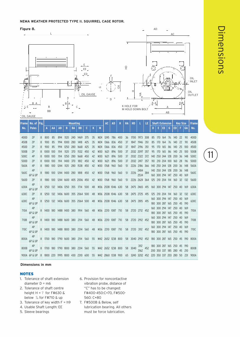
Figure 8.
NEMA WEATHER PROTECTED TYPE II. SQUIRREL CAGE ROTOR.
F
D
GAG
HD
H
HA
A A
A
AB
A AK HOLE FORM HOLD DOWN BOLT
AD
ACL
ED
EE
E
B AB AB
BB
L E C
OIL INLET
OIL OUTLET
OIL GAUGE
OIL GAUGE
400D 2P 8 800 85 894 1120 240 1469 375 35 M24 1245 786 400 36 1700 1973 308 85 170 164 76 140 22 90 400D
450B 2P 8 900 85 994 1000 280 1418 425 35 M24 1366 836 450 37 1847 1946 351 85 170 164 76 140 22 90 450B
450D 2P 8 900 85 994 1250 280 1668 425 35 M24 1366 836 450 37 1847 2196 351 95 170 165 86 140 25 100 450D
500B 2P 8 1000 100 1114 1120 370 1532 450 42 M30 1621 896 500 37 2032 2097 357 95 170 165 86 140 25 100 500B
500C 4P 8 1000 100 1114 1250 280 1668 450 42 M30 1621 896 500 37 2032 2322 372 140 250 244 128 200 36 148 500C
500D 2P 8 1000 100 1114 1400 370 1812 450 42 M30 1621 896 500 37 2032 2417 357 110 210 204 100 160 28 116 500D
560A 4P 8 1180 100 1244 1120 280 1538 450 42 M30 1768 960 560 51 2226 2186 366 140 250 244 128 200 36 148 560A
560C4P
8 1180 100 1244 1400 280 1818 450 42 M30 1768 960 560 51 22262484
384140 250 244 128 200 36 148
560C6P & UP 2534 160 300 294 147 250 40 169
560D 2P 8 1180 100 1244 1600 405 2006 450 42 M30 1768 960 560 51 2226 2624 364 125 210 204 114 160 32 132 560D
630A4P
8 1250 132 1406 1250 355 1714 500 48 M36 2038 1046 630 58 2475 2465 415 160 300 294 147 250 40 169 630A6P & UP
630C 2P 8 1250 132 1406 1600 355 2064 500 48 M36 2038 1046 630 58 2475 2725 415 125 210 204 114 160 32 132 630C
630C4P
8 1250 132 1406 1600 355 2064 500 48 M36 2038 1046 630 58 2475 2815 415160 300 294 147 250 40 169
630C6P & UP 180 300 287 165 250 45 190
710A4P
8 1400 180 1488 1400 380 1914 560 48 M36 2210 1087 710 58 2720 2712 452160 300 294 147 250 40 169
710A6P & UP 180 300 287 165 250 45 190
710B4P
8 1400 180 1488 1600 380 2114 560 48 M36 2210 1087 710 58 2720 2912 452160 300 294 147 250 40 169
710B6P & UP 180 300 287 165 250 45 190
710C4P
8 1400 180 1488 1800 380 2314 560 48 M36 2210 1087 710 58 2720 3112 452160 300 294 147 250 40 169
710C6P & UP 180 300 287 165 250 45 190
800A4P
8 1700 180 1790 1600 380 2114 560 55 M42 2652 1238 800 58 3040 2912 452 180 300 287 165 250 45 190 800A6P & UP
800B4P
8 1700 180 1790 1800 380 2314 560 55 M42 2652 1238 800 58 30403112
452180 300 287 165 250 45 190
800B6P & UP 3162 200 350 337 185 280 45 210
900A 6P & UP 8 1800 220 1995 1800 430 2310 600 55 M42 2860 1338 900 65 3240 3202 452 220 350 337 203 280 50 231 900A
Frame No. of Fig. Mounting AC AD H HA HD L LE Shaft Extension Key Size Frame
No. Poles A AA AB B BA BB C K M D E EE G ED F GA No.
NOTES1. Tolerance of shaft extension
diameter D = m62. Tolerance of shaft centre
height H = -0-1 for F#630 &
below -0-1.8 for F#710 & up
3. Tolerance of key width F = h94. Usable Shaft Length: EE5. Sleeve bearings
6. Provision for noncontactivevibration probe, distance of“C” has to be changed:F#400-450:C+70, F#500-560: C+80
7. F#500B & Below, selflubrication bearing. All othersmust be force lubrication.
Dimensions in mm
12
TE
CO
Wo
rld
wid
eO
per
atio
ns HEAD OFFICE
Teco Electric & Machinery Co. Ltd10F No, 3-1, Yuan Cyu St. Nan-Kang Taipei 115Taiwan ROCTel: +886 2 6615 9111www.teco.com.tw
UNITED STATESTeco-Westinghouse Motor CompanyPO Box 227 (78680-0277)5100 N.IH35Round Rock Texas 78681 USATel: +1 512 255 4141
+1 800 873 8326www.tecowestinghouse.com
CANADATeco-Westinghouse Motors Inc. (Canada)18060-109th Ave Edmonton, Alberta T5S 2K2 CanadaTel: +1 780 444 8933Fax: (780) 486-457524 HR Emergency Pager: (780) 419 7734Toll Free: 800-661-4023Fax Toll Free: 888-USE-TWMIwww.twmi.com
UNITED KINGDOMTeco Electric Europe Ltd.26 Bond,Europa WayOld Trafford, ManchesterM17 1WF England Tel: +44 161 877 8025www.teco.co.uk
NETHERLANDSTeco Electric & Machinery B.V.Teco's European Head OfficeRivium 3e Straat 272909 LH Capelle a/d IJsselThe NetherlandsTel: + 31 10 266 6633Fax: + 31 10 202 6415
GERMANYTeco Electric & Machinery B.V.Niederlassung DeutschlandMarktstrasse 6937441 Bad SachsaGermanyTel: +49 5523 95340Fax: +49 5523 953424www.teco-westinghouse.de
SPAINTeco Electric & Machinery B.V. Spain OfficeC/Sancho Dávila 8 40F28028 Madrid SpainTel: +34 91 725 1718
SOUTH AFRICAArmCoil Afrika (Pty) Ltd.Unit 3 Prestige Park 127 Main Reef RoadTechnikon Roodepoort PO Box 500 Maraisburg 1700 Gauteng South AfricaTel: +2711 763 2351Fax: 0866 318 588www.armcoil.co.za
AUSTRALIATeco Australia Pty Ltd.335-337 Woodpark RoadSmithfield NSW 2164 AustraliaTel: +61 2 9765 8118www.teco.com.au
NEW ZEALANDTeco New Zealand Pty Ltd.Unit 3 477 Great South RoadPenrose Auckland New ZealandTel: +64 9 526 8480
JAPANSankyo Co., Ltd.26th fl. World Trading Center Bldg. 2-4-1 Hamamatsucho Minato-ku Tokyo Japan 105-6126Tel: +81 3 3435 9729 Fax: +81 3 3578 8381
SINGAPORETeco Electric & Machinery (PTE) Ltd.18 Chin Bee DriveSingapore 619865Tel: +65 6 265 4622www.teco.com.sg
INDONESIAP.T. Teco Multiguna ElektroJL Bandengan Utara No. 83/1-3Jakarta Utara-14400 IndonesiaTel: +62 21 662 2201
CHINAShanghai OfficeRm 321 Building No.6 Lane 1279 Zhongshan W. Rd. Shanghai. PRCTel: +86 21 5116 8255Fax: +86 21 6278 8761
Wuxi Teco Electric & Machinery Co., Ltd.No. 9 South Of Changjiang Road, New Zone, Wuxi, Jiangsu Province, PRCTel: +86 510 8534 2005Fax: +86 510 8534 2001www.wuxiteco.com
Jiangxi Teco Electric & Machinery Co.,Ltd1328 Jinggangshan Rd., Nanchang,Jiangxi, PRCTel: +86 791 641 3690Fax: +86 791 641 4228
Suzhou Teco Electric &Machinery Co., LtdNo. 1 Changjiang W.Rd. South-DamIndustrial Park Liuhe ZhenTaicang City, Suzhou,Jiangsu Province, PRCTel: +86 512 5361 9901Fax: +86 512 5396 1058
HONG KONGTecoson Industrial Development (HK) Co., Ltd.Rm 3712 Hong Kong Plaza186-191 Connaught Rd. WestHong Kong Tel: +852 2858 3220
MALAYSIASTE Marketing SDN BHD6 Jalan Firma 2 Kawasan Perind. Tebrau181100 Johor Bahru Johor MalaysiaTel: +60 7 354 8008
THAILANDTeco Electric & Machinery (Thai) Co., Ltd.128/1 Soi WatsrivareenoiMoo 7 Bangna-Trad Road Km 18Bangchalong BangpleeSamuthprakarn 10540 ThailandTel: +662 3371311- 20
NOV. ’06/TA-5402