Large AHU Economizer Configuration and Control · Large AHU Economizer Configuration and Control...
65
Large AHU Economizer Configuration and Control Fachgesprach 7 ☺ WTF Institute of Higher Learning ☺
Transcript of Large AHU Economizer Configuration and Control · Large AHU Economizer Configuration and Control...

Large AHU Economizer
Configuration
and
Control
Fachgesprach 7
☺ WTF Institute of Higher Learning ☺
The Functions of an Economizer System
–
Air Econo Not reqd. by Code when:123

Sick Economizers
•
•
•
•
•
Economizers show a h igh rate o f fa i lure in the study. Of the uni ts equipped wi th economizers , 64% were not operat ing correct ly.Fa i lure modes inc luded dampers that were stuck or inoperable (38%) , sensor or contro l fa i lure (46%) , or poor operat ion (16 %) .The average energy impact o f inoperable economizers i s about 37% of the annua l coo l ing energy ( Jacobs et a l . 2003 ) .C a l i fo r n i a E n e rg y C o m m i s s i o n " S m a l l S y s t e m D e s i g n G u i d e " . Q u o t e d i n A S H R A E D a m p e rs a n d A i r F l o w C o n t ro l

WARNING! "…here be dragons!"
If you think controlling tall building economizers is simple:
You need to step out of the office more …and talk to our star t-up
and commissioning techs …and DDC programmers …
in the field !

So What is the Big Deal? Why Worry?
• Multiple Control Loop interactions in the building• Now this can keep control engineering PhDs at NASA awake at night – but we
will cheerfully ignore this. It is not going to kill anyone. And our start-up and commissioning guys always figure ways around it in the field. ☺
[Alan will talk a little later about his experience.]
• Unintended reverse flow through dampers
• Stack effect in tall buildings
• Wind gust effects on exposed sensors
• Elevator car "piston" effects on Lobby pressure
• Tall Building static pressure sensor location (Lobby?)
• Maintaining minimum outside air levels at different flow rates
• Integrated economizer effect on DX compressors
• ETC. ETC. ETC.

•
•
•
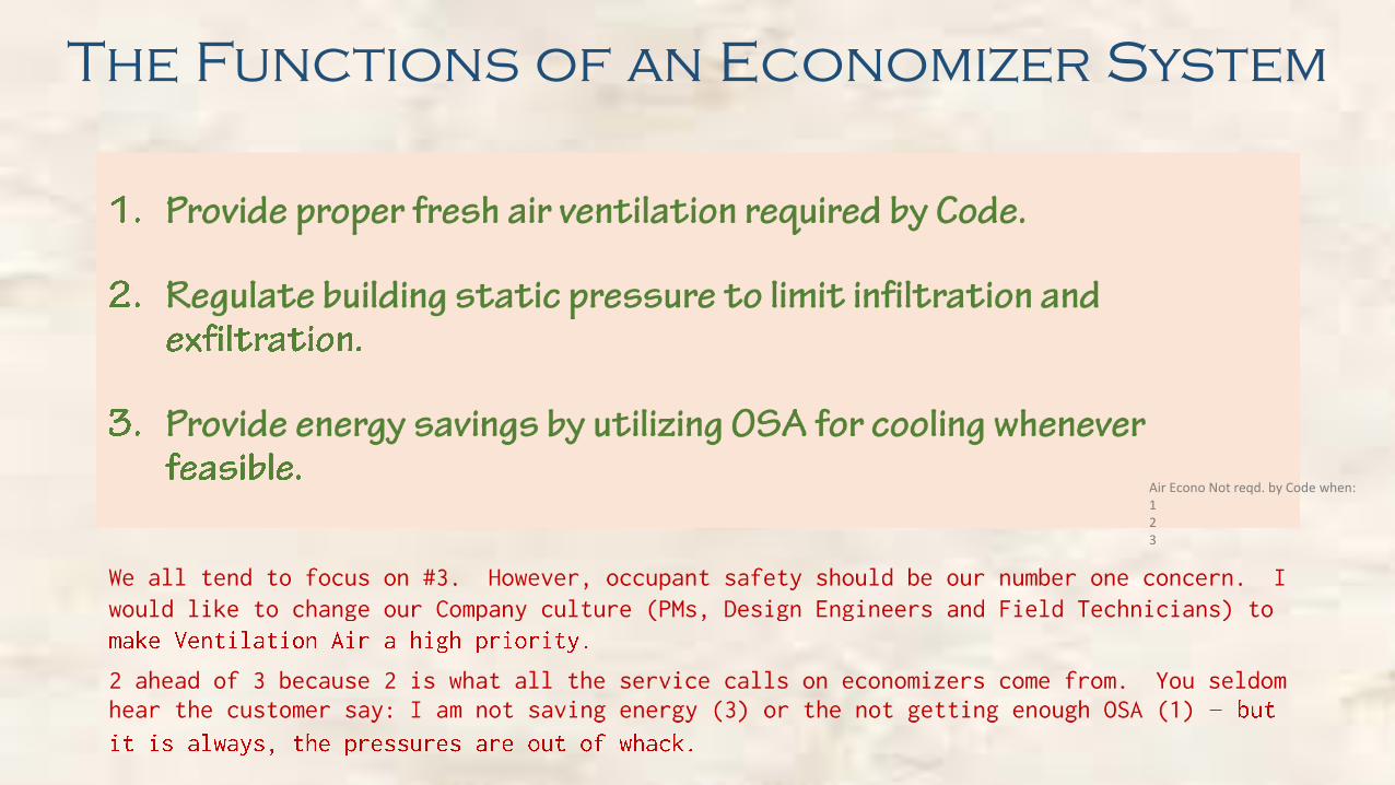
Config – 1
Relief Damper
OSA > Exhaust = Space Positive
OSA < Exhaust = Space Negative ≈
≈
≈
≈
RA Path Pressure Drop < 0.8" W.G.Min OSA Controlled by constant MA plenum pressure

WTF Insight Slide #1
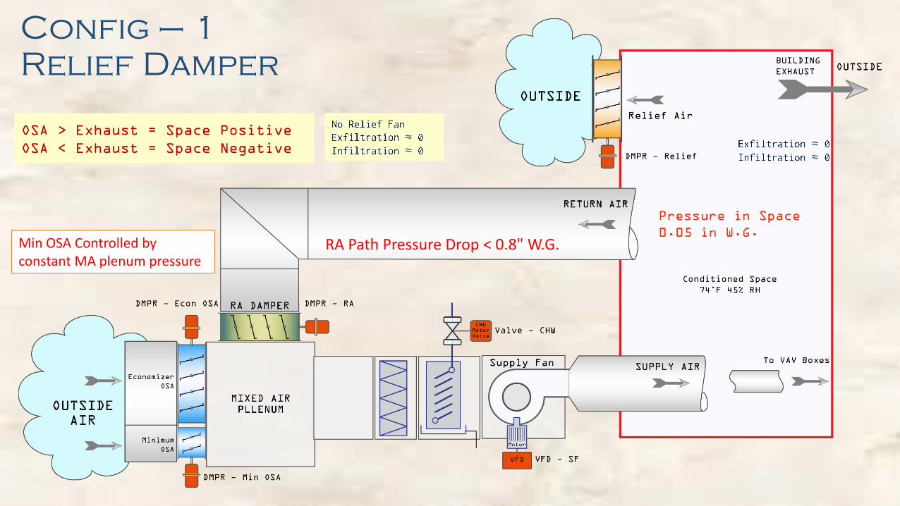
What is a Good Value for Space Static ?
Mat & Tani asking the Mosque facilities manager about good "space-static" values. ASHRAE News
±SLOW down the controller PID … a couple of points above or below set-point is not going
to hurt anything!
Remember: 1" W.G. = 5.2 PSF
Therefore, every tenth of an inch static is roughly ½ PSF
So a tenth of an inch on a 3' x 7' door is how much?

Config – 1
Relief Damper - Summary
• Wel l su i ted for s ing le story structures and also ta l l open structures where motor ized vents can be instal led on the roof
• To use th is conf igurat ion the Rel ief Path must be ver y d i rect - less than 0.1" loss . Else, the space pressure r i ses
• Use motor ized Rel ief Dampers (not gravi ty type).
• For non-cr i t i cal pressure appl icat ions do not instal l ba lanc ing dampers in the OSA path. Balancing dampers waste energy.Des ign to take advantage of the increased f low dur ing OSA mode. (SA set -point reset . )
• Reduce the RA path pressure drop to below 0.8" W.G. May require RA duct veloc i ty reduct ion. Use low loss e lbows and transi t ions.
• I t i s the least expens ive of the 3 opt ions
• I t i s the eas iest to control of the 3 opt ions
• There are never any noise i ssues
Minimum OSA Control Strategy same as for Conf ig-2A.(D iscussed later. )

Other Methods of Introducing Minimum OSA
•
•
•
•
•
•
Note: DCV may be REQUIRED by Code. Not discussed here.

Config – 2A
Relief Fan
RA Path Pressure Drop < 0.8" W.G.

•
•
•
(Both dampers are 2 position and both are wide open.)
If we hold the point B at -0.75", then an air f low rate (CFM) wil l set up which gives a 0.75" pressure drop from A to B.
Also, an air f low rate wil l set up through the blue damper which produces a pressure drop of 0.75" across the damper, C to B.
Suppose we want 2,000 CFM through the blue damper. We can "reverse" look -up the manufacturer's performance data to see what size (or area) damper wil l give us 2,000 CFM @ 0.75" W.G. drop.
As long as the plenum B pressure is maintained at -0.75" W.G. it is guaranteed that the f low across the blue damper wil l be 2,000 CFM
Where did the value -0.75" W.G. come from? If the value 0.75" was selected because it is the ful l RA f low pressure drop from A to B, (with the green return damper ful ly open), then: it wil l always guarantee that with the return damper ful ly open and minus 0.75 in the plenum B, we wil l be able to get ful l RA f low.-0.75 in W.G.
0 in W.G.
0 in W.G.
Return From Space
Mixing Box
Return Duct Loss From A to B = 0.75"
WTF Insight Slide #2

Reduced Flow-0.4" W.G
0 in W.G.
0 in W.G.
Control System Design
THE CHALLENGE:Maintain a minimum injection of outside air (ventilation code) into the mixing plenum (for VAV systems) at all supply fan speeds.
When the supply fan is running at ful l capacity, we have a negative 0.75" W.G. in the mixing plenum and we are drawing 2.000 CFM through the blue minimum outside air damper.
Now suppose the building load decreases, and the VAV boxes downstream start to close. The supply fan responds (duct static) by slowing down.
The pressure in the mixing plenum wil l become LESS NEGATIVE, say -0.4" W.G.
This 0.4" W.G. differential is not large enough to draw in the 2,000 CFM it was doing when the differential was 0.75" W.G. and the f low might drop to say 1,460 CFM
The system now is no longer in compliance with the code
As the supply fan slows down:The plenum pressure rises (less negative)For e.g. -0.4" W.G.Now there is less suction driving from C to B.
WTF Insight Slide #3
Reduced FlowReturn Duct Loss From A to B = 0.4" W.G.

Config – 2A
Relief Fan - Summary
• Always use th i s conf igurat ion as your f i rs t cho ice in "Mid" s i ze bu i ld ings w i th P lenum Return
• De-couple the re l ief fan f rom return a i r ductwork whenever poss ib le
• For our min. OSA st rategy, the Mixed A i r P lenum pressure has to be he ld constant at :
= (R A path pressure drop – Space S tat i c )
= (0 . 75 – 0. 05) = 0 . 70" W.G .
• This insures that w i th R A damper wide open the fu l l des ign R A wi l l f low
• Reduce the R A path pressure drop to be low 0 . 8" W.G. May requi re R A duct ve loc i ty reduct ion and low loss e lbows and t rans i t ions .
• Becomes squi r re l ly i f too negat ive . Use a max . o f -0 . 8" W.G.
• -0 . 8"W.G. i s -4 . 2 PSF on P lenum Wal l s . S t ructura l check .
• S i ze Min imum OSA Damper such that the Min. OSA per code f lows across i t when the pressure d i f ferent ia l across i t i s 0 . 7" . Adjust for duct and louver loss i f any
• Fan energy i s less that that o f R A fan system. Less hours o f Op. And R A path loss p icked up more ef f i c ient ly by la rger SA Fan
PlenumPressure
- 0.7" W.G.
Pressure Loss0.75" W.G.

Config – 2B
Relief Fan

Config – 2B
Relief Fan• Everything is the same as 2A except the
Relief is now directly connected to the RA duct or shaft
• Note extra RA static burden on Rel Fan as compared to Config -2A
• Caution:
• I f the pressures in plenums get messed up we can have Relief Fan exhausting OSA
• The Relief/Return Plenum maybe half an inch or so negative. I f the Relief Damper opens before the Relief Fan is energized, the Relief fan wil l spin backwards before it gets the start s ignal. Not good.
Return/ReliefPlenumReturn/ReliefPlenumReturn/ReliefPlenum

Config – 3
Return Fan

•
•
•
•
•
•
•
•–
Config – 3
Return Fan

How to Draw An Air Side Economizer For Discussion

How to Draw An Air Side Economizer For Discussion
Sample From ASHRAE Guideline 16

Let Us Look At
Config – 2A
In More Detail

Economizer Enable/Disable Trigger
WHEN should the air economizer turn "ON"?(main OSA damper open)
When does it turn "OFF"?(main OSA damper closed)

ASHRAE Standard 90.1-2013
Or Wet BulbOr Wet BulbOr Wet Bulb

Mr. Taylor was one of the primary authors of the HVAC sections of ASHRAE's Standard 90.1 Energy Standard and California's Title 24 Energy Standards. He has designed award winning high performing green buildings and helped pioneer efficient HVAC designs such as underfloor air distribution systems and primary variable flow chilled water systems.
Mr. Taylor was one of the primary authors of the HVAC sections of ASHRAE's Standard 90.1 Energy Standard and California's Title 24 Energy Standards. He has designed award winning high performing green buildings and helped pioneer efficient HVAC designs such as underfloor air distribution systems and primary variable flow chilled water systems.
WHEN should the air economizer turn "ON"?
When does it turn "OFF"?

Why Enthalpy Economizers Don't WorkTaylor & Cheng, ASHRAE Journal, November 2010
"Fixed Dry-Bulbcontrols at the setpoint indicated are the preferred high limit device for all climate zones due to their very low first costs, inherently high energy efficiency, minimal sensor error, minimal energy impact even when there is sensor error, and low maintenance costs. "

ErrorBar
Why Enthalpy Economizers Don't WorkTaylor & Cheng, ASHRAE Journal, November 2010

Conclusion Economizer Types
Reduce Stress In Your Life:
Keep Things Simple
Use A FIXED DRY-BULB Set-Point
To Provide Hi-Limit Switch Over
73°F for most of our region
These f@#$king
economizers never work!

The Integrated Economizer
When the mechanical cooling system can SUPPLEMENT the economizer,
the economizer is known as an "integrated" economizer.
For e.g. in an integrated air economizer, with 55°F Supply Air set-point,
if you have 60°F outside air,
and the OSA damper is fully open, (because OSA is cooler than RA)
then,
to get 55°F Supply Air from the unit,
the mechanical cooling is turned ON
(while the OSA Damper is held wide open)
OSA Damper Fully Open + Mechanical Cooling ON = Integrated Economizer Mode


Economizer Dampers

Control Damper Notes - Damper Types

Control Damper Notes - Authority
•

•
Control Damper Notes #2
Belimo – Damper Applications Guide
Sub Sys -1 Sub Sys -2

Config – 2A Sub-Systems
C
A
B
For calculating the RA damper AUTHORITY, we use the pressure drop from the sub-system "A" to sub-system "B". That is, the pressure drop of the RA path from space to MA plenum.
For calculating the OSA damper AUTHORITY, we use the pressure drop from the sub-system "C" to sub-system "B".
The Relief Damper is full duct size.

Control Damper Notes - Parallel Blade Curves
Oversized Damper
Low Authority
Linear30% to 50%Authority
Red Dots = Linear
DDCOutput
To Actuator
Adapted From: Belimo – Damper Applications Guide
25%Controller
Output

Control Damper Notes – Opposed Blade Damper
Oversized Damper
Low Authority
Linear10% to 15%Authority
Red Dots = Linear
Adapted From: Belimo – Damper Applications Guide
DDCOutput
To Actuator
UndersizedDamper
Curve

Adapted From: Belimo – Damper Applications Guide

Sizing the RA Damper
C
A
B
Pressure Drop from A to B is 0.75" W.G. Including the damper itself.
RA Damper
Please IGNORE THE GENERIC PB DAMPER PICTURE
Let us use an OPPOSED Blade Damper.You could use a PB also – Just size it for proper Authority.OB here keeps the Total Loss for RA path low. PBs needs more "choke" for linear operation.

Adapted From: Belimo – Damper Applications Guide

Sizing the RA Damper
C
A
B
Pressure Drop from A to B is 0.7" W.G. Including the damper itself.
RA Damper
Please IGNORE THE GENERIC PB DAMPER PICTURE
Let us use an OPPOSED Blade Damper.You could use a PB also – Just size it for proper Authority.OB here keeps the Total Loss for RA path low. PBs needs more "choke" for linear operation.

Control Damper Sizing
Using AuthorityC0 = 2.9AMCA Figure 5.2 & 5.4
Use Manufacturer'sPerformance Data

Control Damper Sizing
Using Authority
–
C0 = 2.9AMCA Figure 5.2 & 5.4

Control Damper Sizing
Using Authority
–
C0 = 2.9AMCA Figure 5.2 & 5.4

Control Damper - Pricing

• Always include a detailed damper schedule on your drawings. See Text box on the right
• If you have not sized and planned your economizer dampers – chances are a 100%, the economizer will not work as intended.
• (I mean getting all 3 functions of the economizer operating properly.)
Control Damper Schedule
Damper Schedule Columns:
• Function (e.g. Modulating, Isolation)
• Blade pattern (parallel, opposed, single)
• Blade type (3V, airfoil)
• Frame style (in-duct, flanged)
• Insulated (yes, no)
• Design air flow rate (CFM)
• Design velocity (FPM)
• Pressure drop (" W.G.)
• Damper size (w" x h")
• Opening/duct size (w" x h")
• Fail position (open, closed, last position)
• Other pertinent information
Don't let this old fart scare you … I
can make any damper work!

Controlling The Economizer

• Various Housekeeping Programming Chores Not Described in the Following Slides• e.g.
• Optimum Start
• Temps and Humidities not used in SOP but needed for display
• Pressure drops across filters etc.
Sequence Of Operation - 1

•
•
•
•
•
Sequence Of Operation - 2
NOTE: (Next 2 Slides)Set-Points shown "hard coded" for simplicity. In practice these would be adjustable variables and some will have reset schedules.

Config – 2A The Controlled Outputs

OUTPUT Control Strategy Inputs Required
>
≤ ≤
>
≤ ≤
OUTPUT Control Strategy Inputs Required
>
≤ ≤
>
≤ ≤
OUTPUT Control Strategy Inputs Required
>
≤ ≤
>
≤ ≤

Sample Graphical Programming
Relief Fan VFD Speed
PID Output 0-100%PID
>7%
&Supply fan Status
Enable
Space Static
ReliefDamper
Set NetworkVariable
Relief Damper Control

Space Static Control
Protect Tip from wind gusts
Protect Tip from elevator travel and door openings

Duct Static Control

Sequence Of Operation OSA Damper
>
≤ ≤

OSA Damper Control

Sequence Of Operation RA Damper
>
≤ ≤

RA Damper Control

Sequence Of Operation OSA + RA Dampers

Chilled Water Valve Control•
•
•
•

Packaged Roof-Top Unit Economizers

Crazy Shit!
OPTIONAL???
Note -1 : For l a r ge roo f - t op package un i t s , i t m igh t make s ense
t o p rov ide s epar a t e r e l i e f when :
1 . Space p r e s sur i za t ion prob l ems pe r s i s t ( s ee Note - 2 )
2 . Or r e l i e f a i r i s be ing sucked in to the OSA open ing
Note -2 : Wi thout a power exhaus t , the p r e s sur e d rop th rough the
en t i r e r e l i e f pa th ( a t max . OSA in t ake ) , shou ld no t be more than
about 0 . 1 " WG max . Remember the p r e s sur e d rop o f the r e l i e f
s y s t em becomes the space p r e s sur e .

Is it over ???Good Lord!
for one lousy burrito
WTF was that all about?

TheEND

Barometric Relief
Damper Curve