Langley LPR 1710.41 I Procedural Expiration Date: January ... · PDF file4.14 GEOMETRIC...
30
Page 1 of 30 Verify the correct version before use by checking the LMS Web site. Langley Procedural Requirements LPR 1710.41 I Effective Date: January 4, 2017 Expiration Date: January 31, 2022 Subject: Langley Research Center Standard for the Evaluation of Socket and Branch Connection Welds Responsible Office: Safety and Mission Assurance Office CONTENTS PREFACE ....................................................................................................................... 3 P.1 PURPOSE ........................................................................................................ 3 P.2 APPLICABILITY ............................................................................................... 3 P.3 AUTHORITY ..................................................................................................... 3 P.4 APPLICABLE DOCUMENTS ........................................................................... 3 P.5 MEASUREMENT/VERIFICATION.................................................................... 3 P.6 CANCELLATION.............................................................................................. 3 1.0 GENERAL ............................................................................................................ 5 2.0 INSPECTION TECHNIQUES ............................................................................... 5 3.0 VISUAL EXAMINATION (VT) .............................................................................. 6 3.1 METHOD OF INSPECTION.............................................................................. 6 3.2 AREA OF INSPECTION ................................................................................... 6 3.3 INSPECTION PERSONNEL QUALIFICATIONS ............................................. 6 3.4 ACCEPTANCE CRITERIA FOR VISUAL EXAMINATION OF SOCKET AND BRANCH CONNECTION WELDS .............................................................................. 6 3.5 INSPECTION REPORT .................................................................................... 7 4.0 RADIOGRAPHIC INSPECTIONS ........................................................................ 8 4.1 METHOD OF INSPECTION.............................................................................. 8 4.2 PERSONNEL QUALIFICATIONS .................................................................... 8 4.3 SAFETY ............................................................................................................ 8 4.4 SURFACE PREPARATION.............................................................................. 8 4.5 DIRECTION OF RADIATION ........................................................................... 8 4.6 SHIM BLOCK THICKNESS, SIZE, MATERIAL ............................................... 9 4.7 PENETRAMETER SELECTION AND ESSENTIAL HOLES .......................... 10 4.8 IDENTIFICATION MARKERS ........................................................................ 10 4.9 SHIM BLOCK/PENETRAMETER PLACEMENT ........................................... 11 4.10 RADIOGRAPHIC DENSITY ........................................................................... 11 4.11 SOURCE STRENGTH .................................................................................... 11 4.12 SCATTERED RADIATION ............................................................................. 11 4.13 QUALITY OF RADIOGRAPHS ...................................................................... 11 4.14 GEOMETRIC UNSHARPNESS/SOURCE-TO-FILM DISTANCE................... 12 4.15 ACCEPTANCE CRITERIA FOR RADIOGRAPHIC EXAMINATION OF SOCKET AND BRANCH CONNECTION WELDS ................................................... 12 4.16 RADIOGRAPHIC TECHNICAL LOG AND INTERPRETATION REPORT..... 13
Transcript of Langley LPR 1710.41 I Procedural Expiration Date: January ... · PDF file4.14 GEOMETRIC...
Page 1 of 30
Verify the correct version before use by checking the LMS Web site.
Langley Procedural Requirements
LPR 1710.41 I Effective Date: January 4, 2017
Expiration Date: January 31, 2022
Subject: Langley Research Center Standard for the Evaluation of Socket and Branch Connection Welds Responsible Office: Safety and Mission Assurance Office
CONTENTS PREFACE ....................................................................................................................... 3
P.1 PURPOSE ........................................................................................................ 3 P.2 APPLICABILITY ............................................................................................... 3 P.3 AUTHORITY ..................................................................................................... 3 P.4 APPLICABLE DOCUMENTS ........................................................................... 3 P.5 MEASUREMENT/VERIFICATION .................................................................... 3 P.6 CANCELLATION .............................................................................................. 3
1.0 GENERAL ............................................................................................................ 5
2.0 INSPECTION TECHNIQUES ............................................................................... 5
3.0 VISUAL EXAMINATION (VT) .............................................................................. 6 3.1 METHOD OF INSPECTION .............................................................................. 6 3.2 AREA OF INSPECTION ................................................................................... 6 3.3 INSPECTION PERSONNEL QUALIFICATIONS ............................................. 6 3.4 ACCEPTANCE CRITERIA FOR VISUAL EXAMINATION OF SOCKET AND BRANCH CONNECTION WELDS .............................................................................. 6 3.5 INSPECTION REPORT .................................................................................... 7
4.0 RADIOGRAPHIC INSPECTIONS ........................................................................ 8 4.1 METHOD OF INSPECTION .............................................................................. 8 4.2 PERSONNEL QUALIFICATIONS .................................................................... 8 4.3 SAFETY ............................................................................................................ 8 4.4 SURFACE PREPARATION .............................................................................. 8 4.5 DIRECTION OF RADIATION ........................................................................... 8 4.6 SHIM BLOCK THICKNESS, SIZE, MATERIAL ............................................... 9 4.7 PENETRAMETER SELECTION AND ESSENTIAL HOLES .......................... 10 4.8 IDENTIFICATION MARKERS ........................................................................ 10 4.9 SHIM BLOCK/PENETRAMETER PLACEMENT ........................................... 11 4.10 RADIOGRAPHIC DENSITY ........................................................................... 11 4.11 SOURCE STRENGTH .................................................................................... 11 4.12 SCATTERED RADIATION ............................................................................. 11 4.13 QUALITY OF RADIOGRAPHS ...................................................................... 11 4.14 GEOMETRIC UNSHARPNESS/SOURCE-TO-FILM DISTANCE ................... 12 4.15 ACCEPTANCE CRITERIA FOR RADIOGRAPHIC EXAMINATION OF SOCKET AND BRANCH CONNECTION WELDS ................................................... 12 4.16 RADIOGRAPHIC TECHNICAL LOG AND INTERPRETATION REPORT ..... 13
1/4/2017 LPR 1710.41 I
Page 2 of 30
Verify the correct version before use by checking the LMS Web site.
5.0 MAGNETIC PARTICLE/DYE PENETRANT INSPECTIONS ............................. 14 5.1 GENERAL ...................................................................................................... 14 5.2 INSPECTION TECHNIQUES .......................................................................... 14 5.3 ACCEPTANCE CRITERIA FOR MAGNETIC PARTICLE AND DYE PENETRANT EXAMINATION OF SOCKET AND BRANCH CONNECTION WELDS ...................................................................................................................... 15 5.4 INSPECTION REPORT .................................................................................. 15
APPENDIX A – ACRONYMS ....................................................................................... 16
APPENDIX B – FIGURES ............................................................................................ 17 B-1. SOCKET-WELD FITTING JOINT NOMENCLATURE ................................... 17 B-2. UNACCEPTABLE SOCKET-WELD LEG SIZE ............................................. 17 B-3. SURFACE CRACKING .................................................................................. 18 B-4. SURFACE INCOMPLETE FUSION ................................................................ 18 B-5. UNDERCUT .................................................................................................... 19 B-6. SURFACE SLAG AND POROSITY ............................................................... 19 B-7. RADIOGRAPHIC EXPOSURE TECHNIQUE FOR SOCKET WELDING FITTINGS .................................................................................................................. 20 B-8. INTERNAL CRACKS ..................................................................................... 21 B-10. INCOMPLETE FUSION .............................................................................. 23 B-11. UNACCEPTABLE PIPE-TO-SOCKET GAP ............................................... 24 B-12. POROSITY AND ROUNDED INDICATIONS .............................................. 25 B-13. SLAG INCLUSIONS ................................................................................... 26 B-14. MELT THROUGH ....................................................................................... 27 B-15. NOMENCLATURE FOR BRANCH-CONNECTION WELDS ...................... 28 B-16. RADIOGRAPHIC EXPOSURE TECHNIQUE FOR BRANCH CONNECTION FITTINGS .................................................................................................................. 29 B-17. INCOMPLETE PENETRATION IN BRANCH CONNECTION FITTINGS ... 30

1/4/2017 LPR 1710.41 I
Page 3 of 30
Verify the correct version before use by checking the LMS Web site.
PREFACE
P.1 PURPOSE a. This document sets forth the minimum safety procedural requirements for evaluating
socket and branch connection welds within the framework of Langley Research Center (LaRC).
b. It provides professional designers and craftsmen a basis for safety and uniformity in the design, fabrication, and inspection of welded piping systems.
P.2 APPLICABILITY a. These procedural requirements apply to all persons performing work at LaRC,
including civil servants; contractors, to the extent required by their contracts; research associates; and others.
b. Non-compliance with this LPR will result in appropriate disciplinary action that may include termination for a civil servant employee or exclusion from LaRC for a contractor employee, research associate, or others.
P.3 AUTHORITY National Aeronautics and Space Act, 51 U.S.C. 20113(a)
P.4 APPLICABLE DOCUMENTS a. LPR 1710.5, Ionizing Radiation b. LPR 1710.40, Langley Research Center Pressure Systems Handbook c. ASME Boiler and Pressure Vessel Code (B&PVC) and B31 Piping Codes d. ASME B16.11, Forged Fittings, Socket Welding and Threaded e. ASME B16.34, Valves – Flanged, Threaded, and Welding End f. ASNT SNT-TC-1A, Personnel Qualification and Certifications in Nondestructive
Testing g. Manufacturers Standardization Society (MSS)-SP-97, Integrally Reinforced Forged
Branch Outlet Fittings, Socket Welding, Threaded, and Butt Welding Ends
P.5 MEASUREMENT/VERIFICATION None
P.6 CANCELLATION 1710.41 H, Langley Research Center Standard for the Evaluation of Socket and Branch Connection Welds, dated July 27, 2011.
1/4/2017 LPR 1710.41 I
Page 4 of 30
Verify the correct version before use by checking the LMS Web site.
/s/ Clayton P. Turner January 4, 2017 Center Deputy Director Distribution: Approved for public release via the Langley Management System; distribution is unlimited.

1/4/2017 LPR 1710.41 I
Page 5 of 30
Verify the correct version before use by checking the LMS Web site.
CHAPTER 1
1.0 GENERAL 1.1 This procedural requirement shall be used for the nondestructive evaluation of
socket and branch connection welds at LaRC. 1.2 Socket fittings include, but are not limited to, all common pipe fittings (e.g., tees,
elbows, couplings, caps, flanges, unions, and valves meeting the requirements of ASME B16.11, “Forged Fittings, Socket Welding and Threaded,” and ASME B16.34, “Valves – Flanged, Threaded, and Welding End”).
1.3 Branch connections are defined as Weld-O-Let, Sock-O-Let, Thread-O-Let, or
other similar commercial fittings made in accordance with MSS-SP-97, “Integrally Reinforced Forged Branch Outlet Fittings, Socket Welding, Threaded, and Butt Welding,” and include modified components such as couplings.
1.4 The exterior weld of slip-on flanges may be inspected using this standard. 1.5 Reference documents include those published by:
a. American Society for Mechanical Engineers (ASME) b. American Society for Nondestructive Testing (ASNT)
1.6 In this document, all mandatory actions (i.e., requirements) are denoted by
statements containing the term “shall.” The terms “may” or “can” denote discretionary privilege or permission, “should” denotes a good practice and is recommended, but not required, “will” denotes expected outcome, and “are” or “is” denotes descriptive material.
CHAPTER 2
2.0 INSPECTION TECHNIQUES 2.1 Four nondestructive evaluation techniques are available to be used exclusively or
in combination to inspect socket type and branch connection welds. These techniques are: a. visual examination (VT) b. radiographic examination (RT) c. magnetic particle examination (MT) d. dye penetrant examination (PT)
2.2 Under special circumstances, other techniques (such as eddy current examination or ultrasonic examination) may be required. Their application shall be guided by the appropriate sections of the ASME B&PVC.

1/4/2017 LPR 1710.41 I
Page 6 of 30
Verify the correct version before use by checking the LMS Web site.
CHAPTER 3
3.0 VISUAL EXAMINATION (VT)
3.1 METHOD OF INSPECTION 3.1.1 Socket and branch connection welds shall be inspected for surface defects using visual inspection techniques.
3.2 AREA OF INSPECTION 3.2.1 Visual inspections within the scope of this procedural requirement shall be the weld contour and adjacent pipe and fitting surfaces. 3.2.2 Inspections shall be conducted in accordance with the most current editions of the ASME Code B31.3, and the ASME B&PVC, Section V, Article 9, with the following modifications: Unless otherwise specified, all welds shall be contour ground and free of rust, scale, slag, or other conditions that would obscure the surface condition. The pressure retaining wall thickness shall not be reduced below the Code allowable limits.
3.3 INSPECTION PERSONNEL QUALIFICATIONS a. Inspection personnel shall be currently certified under a plan based on the American
Society for Nondestructive Testing (ASNT) recommended practice SNT-TC-1A "Recommended Practice for Nondestructive Testing Personnel Qualification and Certification” to a minimum qualification of Level II.
b. Inspectors shall have successfully passed an eye examination to demonstrate near distance acuity such as the J-2 letters on a standard Jaeger Test Chart. Eye examinations are required as follows: (1) Under age 35, every 12 months (2) 35 years of age and over, every 6 months
3.4 ACCEPTANCE CRITERIA FOR VISUAL EXAMINATION OF SOCKET AND BRANCH CONNECTION WELDS 3.4.1 Weld fillets shall comply with the requirements of the current edition of ASME B31.3. In lieu of a specified pressure design thickness “t”, the nominal pipe wall thickness “TW” shall be substituted. (See Appendix B, Figures B-1 and B-2.) 3.4.2 The weld surface and adjacent base metal shall be free of cracks, incomplete fusion (IF), arc strikes, weld spatter, gouges, porosity, underfill, overlap, slag inclusion, convexity, concavity, mishandling marks, and other sharp surface irregularities and shall meet all requirements in ASME B31.3 for severe cyclic conditions. 3.4.3 The weld fillet shall blend uniformly into the pipe wall and fitting rim.
1/4/2017 LPR 1710.41 I
Page 7 of 30
Verify the correct version before use by checking the LMS Web site.
3.4.3.1 The undercut shall not exceed the lesser of 1/32 inch or TW/4 (TW = nominal pipe wall thickness). 3.4.4 Surface porosity and/or slag is not permitted. (See Appendix B, Figures B-3 through B-6 for examples of these irregularities.) 3.4.5 Unless otherwise specified, axial misalignment between the pipe and fitting shall not exceed 5°.
3.5 INSPECTION REPORT 3.5.1 Upon completion of visual inspections, the inspecting organization shall furnish a report containing, as a minimum, the following information: a. System identification b. Drawing number c. Location d. Sketch or description of each component/weld e. Material type f. Surface condition g. Discrepancies noted h. Inspector’s name i. Inspection data j. Contract number

1/4/2017 LPR 1710.41 I
Page 8 of 30
Verify the correct version before use by checking the LMS Web site.
CHAPTER 4
4.0 RADIOGRAPHIC INSPECTIONS
4.1 METHOD OF INSPECTION 4.1.1 Socket and branch connection weld joints shall be inspected for defects using radiographic techniques. 4.1.2 These radiographic inspections shall be conducted in accordance with the most current edition of the ASME B&PVC, Section V, Article 2, as modified by the following paragraphs. 4.1.3 Any item not specifically addressed herein will revert to the provisions of ASME B&PVC Section V.
4.2 PERSONNEL QUALIFICATIONS 4.2.1 All inspection personnel shall be qualified in accordance with ASNT SNT-TC-1A. Personnel qualified to Level I shall be used only under the field supervision of Level II or Level III inspectors. 4.2.2 Radiographic film interpreters shall be qualified per ASNT SNT-TC-1A, Level II or Level III, or shall be qualified as a Certified Radiograph Interpreter per American Welding Society (AWS). 4.2.3 Final interpretation and acceptance of radiographs of pressure-retaining items shall be by the LaRC Radiograph Interpreter. 4.2.4 In addition to the above requirement, radiographic interpreters shall have demonstrated near distance acuity as specified under Chapter 3, Paragraph 3.2 of this LPR and shall be familiar with weld fabrication techniques.
4.3 SAFETY 4.3.1 All radiographic inspection operations conducted at LARC shall be in accordance with LPR 1710.5.
4.4 SURFACE PREPARATION 4.4.1 Unless otherwise specified, all welds shall be contour ground and free of surface irregularities which could mask or be confused with discontinuities.
4.5 DIRECTION OF RADIATION 4.5.1 Each socket weld exposure setup shall be aligned so as to pass the radiation central ray parallel to and in line with the socket rim. (See Appendix B, Figure B-7.) 4.5.2 Each branch connection weld exposure setup shall be aligned so as to pass the radiation central ray in a tangent to the run pipe external surface.

1/4/2017 LPR 1710.41 I
Page 9 of 30
Verify the correct version before use by checking the LMS Web site.
4.5.2.1 Two views shall be imaged as follows (see Appendix B, Figure B-16): a. View 0 - with the central ray perpendicular to the run pipe axis. b. View 1 - with the central ray offset 25-35 degrees from View 0.
NOTE
Branch connections over 6 inches in diameter (O.D.) may require additional exposures or alternate techniques at the
discretion of the NASA-NDE Radiograph Interpreter. 4.5.3 The requirements defined within this paragraph 4.5 may, at the discretion of the NASA Non-Destructive Evaluation (NDE) Radiograph interpreter, be relaxed to allow the simultaneous exposure of closely spaced weld joints. 4.5.3.1 Three views of each weld joint taken at 60° to each other is the minimum acceptable coverage for pipe having a nominal size greater than 1 inch. 4.5.3.2 For pipe having a nominal size of 1 inch or less, two views of each weld joint taken at 90° to each other is the minimum acceptable coverage. (See Appendix B, Figure B-7.)
4.6 SHIM BLOCK THICKNESS, SIZE, MATERIAL 4.6.1 The shim block thickness shall be established for each joint by using the
following formulas: a. For socket: 2TW + R b. For branch: 2Tf + R where: (1) Tf = the nominal fitting single wall thickness (2) TW = the nominal pipe single wall thickness (3) R = the component of weld reinforcement measured perpendicular to the pipe
axis at the fitting edge rim. (See Appendix B, Figure B-1 for socket welds and Figure B-15 for branch connection welds.)
4.6.2 The shim block shall be of sufficient size to allow placement of a penetrameter and identification markers.
4.6.3 Shim material shall be radiographically similar to the subject weld/pipe material.

1/4/2017 LPR 1710.41 I
Page 10 of 30
Verify the correct version before use by checking the LMS Web site.
4.7 PENETRAMETER SELECTION AND ESSENTIAL HOLES
4.7.1 The penetrameter selection shall be based on the calculated shim thickness as follows:
SHIM THICKNESS (2TW + R) OR (2Tf + R) PENETRAMETER ESSENTIAL
HOLE
a. 0 thru 0.375 10 4t
b. Over 0.375 thru 0.625 12 4t
c. Over 0.625 thru 0.875 15 4t
d. Over 0.875 thru 1.00 17 4t
e. Over 1.00 thru 1.50 25 2t
f. Over 1.50 thru 2.00 30 2t
g. Over 2.00 thru 2.50 35 2t
4.8 IDENTIFICATION MARKERS 4.8.1 An ID plate is necessary for all high pressure piping and when random or partial
radiographic inspection is instituted. 4.8.2 The ID plate shall be a flexible type plate stamped with the required information
and bonded to the required location on the pipe. 4.8.3 An isometric weld map shall accompany all RT inspections of piping to facilitate
location of welds. 4.8.3.1 If the radiographic view depicts more than one weld joint, identification numbers
shall be included in the image to positively identify each weld. 4.8.4 No low stress stamping or electric etcher or vibratory etching of any piping is
allowed due to the fact that materials in operation under long-term creep or creep fatigue may experience a failure.
4.8.4.1 If marking on a pipe is required, utilize a flexible ID plate as noted in 4.8.2. 4.8.5 Film printer identification techniques are prohibited. 4.8.6 Each radiograph shall, as a minimum, have the following information
permanently included in its image: a. Weld number b. View number
1/4/2017 LPR 1710.41 I
Page 11 of 30
Verify the correct version before use by checking the LMS Web site.
c. NASA Quality Assurance (QA) or contract number
d. Radiographic contractor identification e. Date of exposure f. NASA drawing number g. Welder ID
4.9 SHIM BLOCK/PENETRAMETER PLACEMENT 4.9.1 The shim block with identification numbers and penetrameter shall be aligned
parallel to the subject pipe axis with the penetrameter center adjacent to the socket rim. (See Appendix B, Figure B-7, for socket welds and Figure B-16 for branch connection welds.)
4.10 RADIOGRAPHIC DENSITY 4.10.1 The calculated shim thickness from Chapter 4.6 shall be used to determine
exposure values. 4.10.2 Film image density shall be measured through the shim block/penetrameter
combination and shall equal 3.0 ± 0.5. (See Appendix B, Figure B-7)
4.11 SOURCE STRENGTH 4.11.1 Unless otherwise specified, the radiation source energy shall be equal to or
greater than 35 curies from IR 192 and 150 KEV for x-ray machines.
4.12 SCATTERED RADIATION 4.12.1 To minimize the effect of back scatter radiation, all film cassettes shall be backed
up with a minimum of 1/16 inch-thick lead sheeting. 4.12.1.1 This sheeting shall be at sufficient size to completely cover the cassette and
shall be covered with tape to prevent lead smearing. (See Appendix B, Figure B-7, for socket welds and Figure B-16 for branch connection welds.)
4.13 QUALITY OF RADIOGRAPHS 4.13.1 All radiographs shall be free of mechanical, chemical, or other blemishes that
could mask the image of any discontinuity within the area of interest. 4.13.1.1 Such blemishes include, but are not limited to:
a. Fogging b. Processing defects such as streaks, water marks, or chemical stains c. Scratches, finger marks, crimps, dirt, static marks, smudges, or tears d. Loss of detail due to poor screen-to-film contact e. False indications due to defective screens or cassette faults

1/4/2017 LPR 1710.41 I
Page 12 of 30
Verify the correct version before use by checking the LMS Web site.
4.14 GEOMETRIC UNSHARPNESS/SOURCE-TO-FILM DISTANCE 4.14.1 Geometric unsharpness of the radiographic image shall not exceed 0.020 inch. 4.14.2 The radiation source-to-film distance, unless otherwise specified by the NASA
NDE Radiograph interpreter, shall be not less than 14 inches.
4.15 ACCEPTANCE CRITERIA FOR RADIOGRAPHIC EXAMINATION OF SOCKET AND BRANCH CONNECTION WELDS
4.15.1 The following acceptance criteria apply: a. Cracks of any nature or extent are not acceptable. (See Appendix B, Figure B-8.) b. Incomplete penetration (IP) as follows is not acceptable:
(1) Socket: The failure of weld material to extend completely into and become integral with the intersection of socket rim inner diameter and cylindrical pipe wall. (See Appendix B, Figure B-9.)
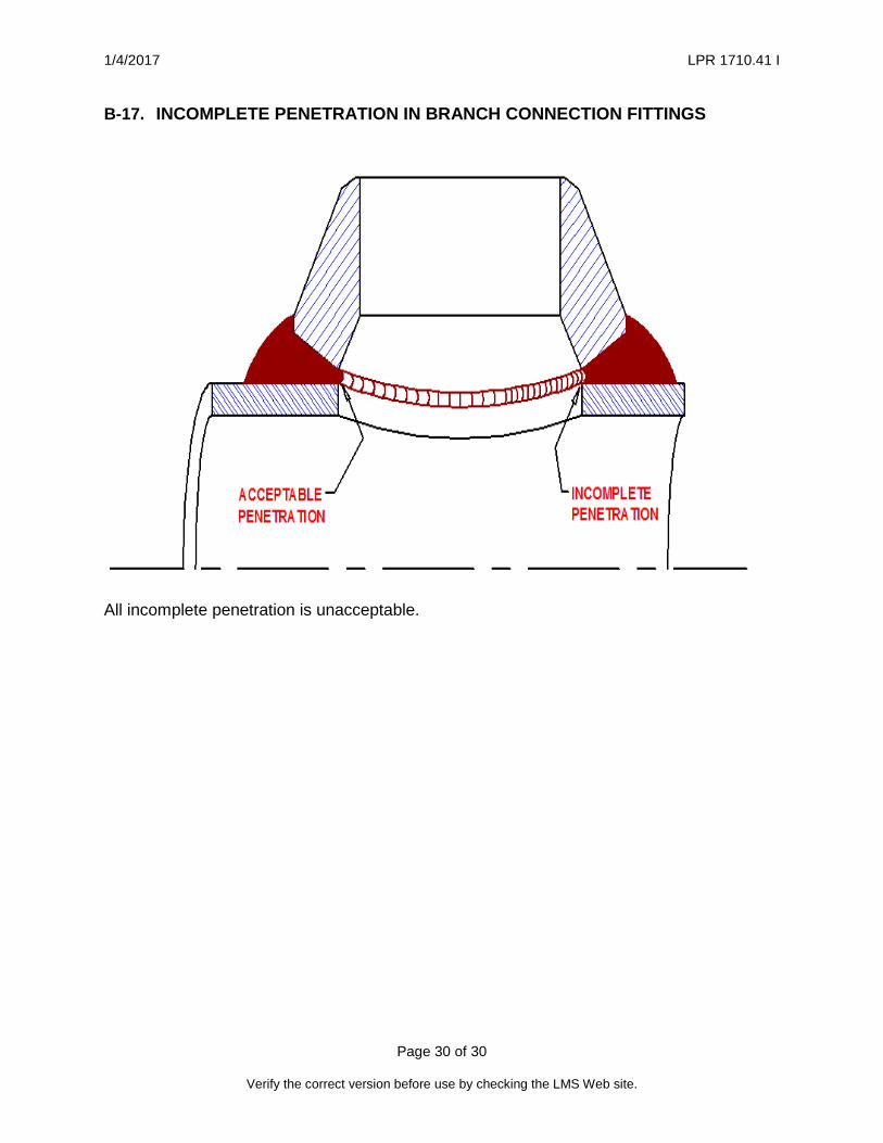
(2) Branch: The failure of the weld material to: (a) extend completely to the inner surface of the fitting, and (b) become integral with both the pipe and the fitting. (See Appendix B,
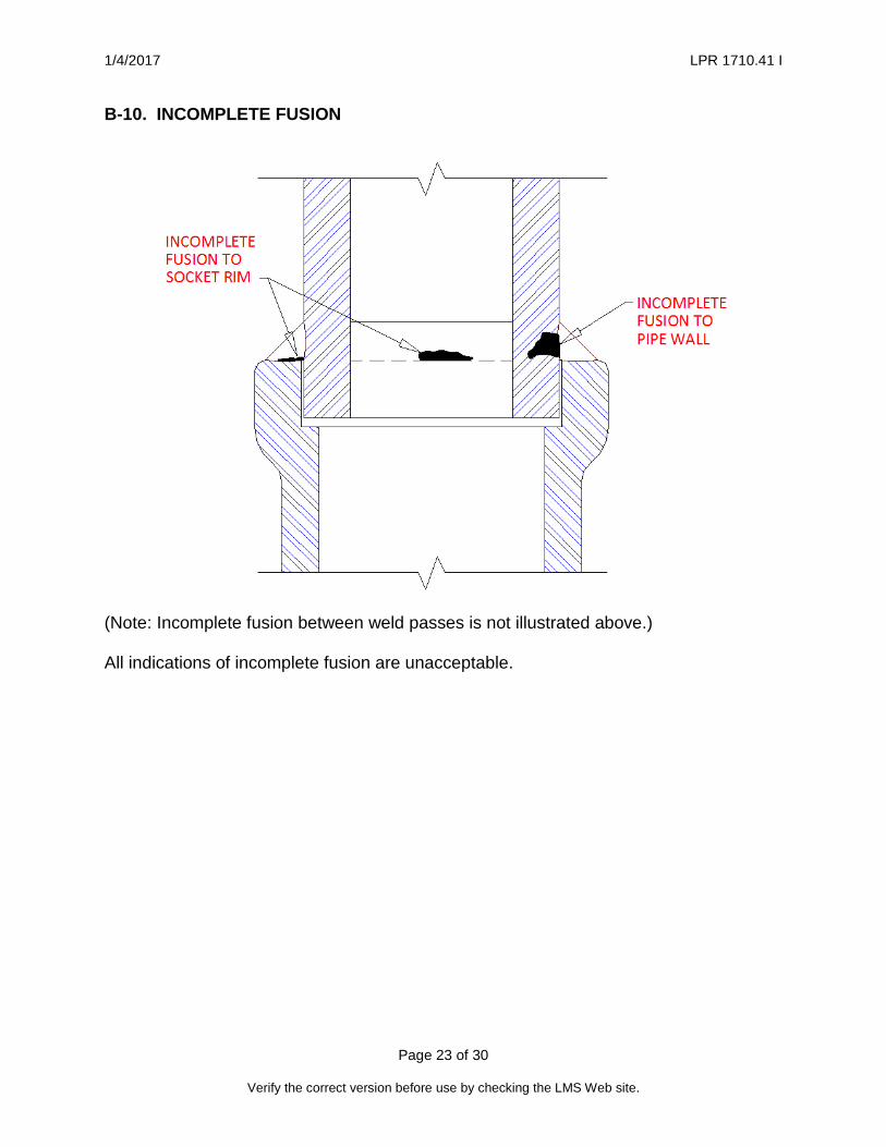
Figure B-17.) c. Incomplete Fusion (IF), an isolated, discontinuous or continuous area of no weld
material fusion at the weld-socket, weld-pipe interface, or between consecutive weld passes, is not acceptable. (See Appendix B, Figure B-10.)
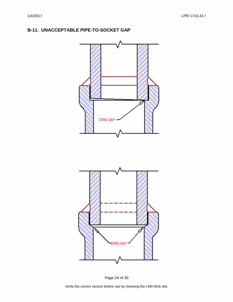
d. For socket welds only, a gap of 1/16 inch ± 1/32 inch shall be maintained between pipe end and socket bottom after welding. (See Appendix B, Figures B-1 and B-11.)
e. An individual porosity defect or rounded indication shall not exceed the lesser of TW/3 or 1/8 inch in its greater dimensions. (1) Adjacent indications shall be separated by a minimum TW/2 of sound weld. (2) The summation of diameters for aligned rounded indications shall not exceed TW
in length for any 6 TW of weld. (See Appendix B, Figure B-12.) f. Slag inclusions/elongated defects requirements are as follows:
(1) The developed length of any single slag inclusion or elongated defect shall not exceed TW/3
(2) Adjacent slag inclusions shall be separated by a minimum TW/2 sound weld. (3) The total cumulative developed length of slag inclusions and/or elongated
defects shall not exceed TW in any 6 TW of weld (4) The width of a slag inclusion shall not exceed the lesser of 3/32 inch or TW/3. (5) Slag inclusions or elongated defects that infringe upon the root area are not
acceptable to any extent. (See Appendix B, Figure B-13.)

1/4/2017 LPR 1710.41 I
Page 13 of 30
Verify the correct version before use by checking the LMS Web site.
g. Melt through, a localized area of pipe metal melting and resolidification usually located on the pipe inner diameter, shall be reviewed on an individual case basis and shall not: (1) Reduce the nominal pipe wall thickness greater than 12.5 percent. (2) Present unacceptable internal flow restrictions as determined by the Standard
Practice Engineer. (3) Include icicle type areas which could become dislodged. (See Appendix B,
Figure B-14) h. Burn through or suck up shall not reduce the nominal pipe wall thickness greater
than 12.5 percent.
4.16 RADIOGRAPHIC TECHNICAL LOG AND INTERPRETATION REPORT 4.16.1 The radiographer shall furnish, in addition to the radiographic film, a technical log
and interpretation report relative to each inspected weld. 4.16.1.1 The log/report shall contain, as a minimum, the following data:
a. System identification b. Drawing number c. Location d. Sketch or description of each component/weld e. Material type f. Pipe nominal wall thickness TW and fitting nominal wall thickness Tf g. Weld thickness R h. Shim block thickness - 2TW + R or 2Tf + R; i. Penetrameter size/essential hole j. Isotope or x-ray machine, size/type/energy k. Film type/manufacturer l. Screen type, thickness, placement m. Source-to-film distance n. Exposure time/milliamp-minutes (MAM) o. Radiographer’s name/level p. Inspection date q. Discrepancies noted r. Interpreter’s name/level s. Interpretation date
1/4/2017 LPR 1710.41 I
Page 14 of 30
Verify the correct version before use by checking the LMS Web site.
CHAPTER 5
5.0 MAGNETIC PARTICLE/DYE PENETRANT INSPECTIONS
5.1 GENERAL 5.1.1 Socket and branch connection weld joints shall be inspected for surface defects
utilizing magnetic particle or dye penetrant techniques, as applicable. 5.1.1.1 This work shall be conducted in accordance with the ASME B&PVC, Section V, Article 7, for magnetic particle and Article 6 for dye penetrant, with the following modifications: 5.1.2 Inspection personnel shall be qualified in accordance with ASNT-SNT-TC-lA.
Personnel qualified to Level I shall be used only under the field supervision of Level II or Level III inspectors.
5.1.3 Weld joint surfaces and adjacent areas (within a minimum of 1 inch on each side of weld) shall be free of any irregularities which could mask indications. All welds having received post weld heat treatment (PWHT) shall subsequently be MT or PT inspected to this LPR and the applicable welding code.
5.1.4 Prior to inspection, these areas shall be dry and free of all paint, dirt, grease, lint, scale, welding flux and splatter, oil or other extraneous matter that could interfere with the examination.
5.2 INSPECTION TECHNIQUES 5.2.1 The following are the two weld joint inspection techniques: a. Magnetic particle technique:
(1) The inspector has the option of using a coil encirclement or yoke magnetization technique.
(2) Magnetizing field adequacy shall be verified using a magnetic particle field indicator as illustrated in ASME B&PVC, Section V, Article 7. This verification shall be conducted at the beginning of each period of work or shift change and as a minimum every 4 hours during the work period.
(3) All surface areas of: (a) the weld and (b) the adjacent pipe and fitting material (for a minimum of 1 inch on each side of the weld) shall be 100 percent inspected.
b. Dye penetrant technique: (1) Unless otherwise specified, dwell time shall be not less than 10 minutes.
(2) When the surface temperature of the area to be inspected is outside of the 60 °F to 125 °F range, the testing procedure shall be qualified as per the requirements of ASME B&PVC, Section V, Article 6.

1/4/2017 LPR 1710.41 I
Page 15 of 30
Verify the correct version before use by checking the LMS Web site.
5.3 ACCEPTANCE CRITERIA FOR MAGNETIC PARTICLE AND DYE PENETRANT EXAMINATION OF SOCKET AND BRANCH CONNECTION WELDS
5.3.1 The following weld defects shall constitute rejectable conditions: a. Cracks b. Incomplete fusion (IF) c. Surface open slag or porosity
5.4 INSPECTION REPORT 5.4.1 Upon completion of magnetic particle and/or dye penetrant inspections, the
inspector shall furnish a report containing, as a minimum, the following information:
a. System identification b. Drawing number c. Location d. Description, sketch, photographs, weld map, description of inspected item e. If dye penetrant technique, report shall include:
(1) Penetrant type/manufacturer (2) Part temperature (3) Dwell time (4) Cleaning method (5) Development method
f. If magnetic particle technique, report shall include: (1) Magnetization method (2) Equipment manufacturer (3) Magnetization current (AC or DC) (4) Magnetization current strength (amps) (5) Power type/manufacturer
g. Discrepancies noted h. Inspector’s name, printed and certified by signature i. Date of inspection
1/4/2017 LPR 1710.41 I
Page 16 of 30
Verify the correct version before use by checking the LMS Web site.
APPENDIX A – ACRONYMS
ANSI American National Standard Institute
ASME American Society for Mechanical Engineer
ASNT American Society for Nondestructive Testing
AWS American Welding Society
BPPVC Boiler and Pressure Vessel Code
IF Incomplete fusion
IP Incomplete penetration
LaRC Langley Research Center
LPR Langley Procedural Requirement
MAM Milliamp-minutes
MSS Manufacturers Standardization Society
MT Magnetic particle examination
NDE Non-destructive evaluation
NRC Nuclear Regulatory Commission
PT Dye penetrant examination
QA Quality Assurance
RT Radiographic examination
VT Visual external examination

1/4/2017 LPR 1710.41 I
Page 17 of 30
Verify the correct version before use by checking the LMS Web site.
APPENDIX B – FIGURES
B-1. SOCKET-WELD FITTING JOINT NOMENCLATURE (excluding socket welds in pipe flanges)
B-2. UNACCEPTABLE SOCKET-WELD LEG SIZE Weld leg size (H or V) less than the greater of 1.25 ·Tw or 1/8 inch is rejectable.
1/4/2017 LPR 1710.41 I
Page 18 of 30
Verify the correct version before use by checking the LMS Web site.
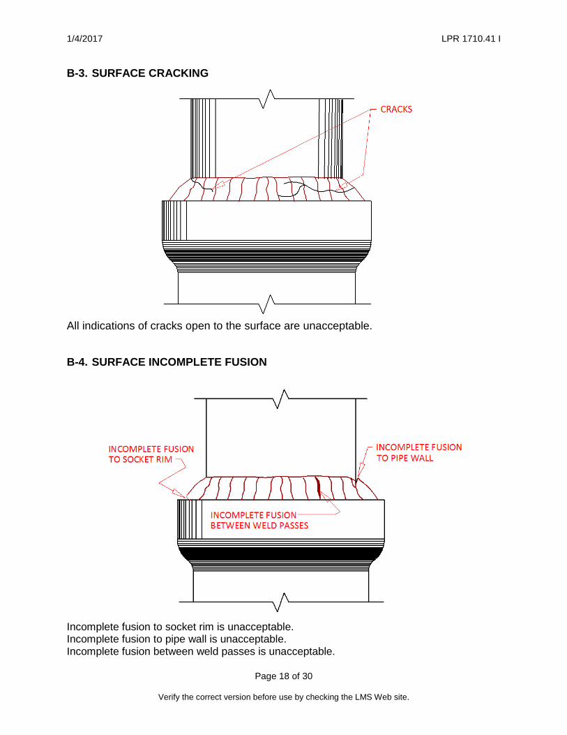
B-3. SURFACE CRACKING
All indications of cracks open to the surface are unacceptable.
B-4. SURFACE INCOMPLETE FUSION
Incomplete fusion to socket rim is unacceptable. Incomplete fusion to pipe wall is unacceptable. Incomplete fusion between weld passes is unacceptable.

1/4/2017 LPR 1710.41 I
Page 19 of 30
Verify the correct version before use by checking the LMS Web site.
B-5. UNDERCUT
Undercut larger than the smaller of 0.25 · Tw or 1/32 inch is unacceptable.
B-6. SURFACE SLAG AND POROSITY
All indications of surface slag and surface porosity are unacceptable.

1/4/2017 LPR 1710.41 I
Page 20 of 30
Verify the correct version before use by checking the LMS Web site.
B-7. RADIOGRAPHIC EXPOSURE TECHNIQUE FOR SOCKET WELDING FITTINGS
Notes:
1. Three (3) views required at 60° radial separation for pipe sizes greater than 1 inch.
2. Two (2) views required at 90° radial separation for pipe sizes 1 inch or less. 3. The following information shall be included in the radiographic image:
• Company Name or Contractor ID • NASA Contract Number or Task Number • Drawing Number • NASA Weld Number • View Identification Numbers • Repair Cycle Number (Rxx) • Date of Inspection • Welder ID

1/4/2017 LPR 1710.41 I
Page 21 of 30
Verify the correct version before use by checking the LMS Web site.
B-8. INTERNAL CRACKS
All crack indications are unacceptable.

1/4/2017 LPR 1710.41 I
Page 22 of 30
Verify the correct version before use by checking the LMS Web site.
B-9. Incomplete Penetration
All indications of incomplete weld penetration are unacceptable.
1/4/2017 LPR 1710.41 I
Page 23 of 30
Verify the correct version before use by checking the LMS Web site.
B-10. INCOMPLETE FUSION
(Note: Incomplete fusion between weld passes is not illustrated above.)
All indications of incomplete fusion are unacceptable.
1/4/2017 LPR 1710.41 I
Page 24 of 30
Verify the correct version before use by checking the LMS Web site.
B-11. UNACCEPTABLE PIPE-TO-SOCKET GAP

1/4/2017 LPR 1710.41 I
Page 25 of 30
Verify the correct version before use by checking the LMS Web site.
B-12. POROSITY AND ROUNDED INDICATIONS
Not less than 0.5 ∙Tw separation. Greatest dimension of rounded indications and porosity shall not exceed 0.3 ∙ Tw.

1/4/2017 LPR 1710.41 I
Page 26 of 30
Verify the correct version before use by checking the LMS Web site.
B-13. SLAG INCLUSIONS
Largest dimension of largest slag inclusion shall not exceed 0.3 ∙ Tw. Slag inclusions at the root of the socket weld are unacceptable.

1/4/2017 LPR 1710.41 I
Page 27 of 30
Verify the correct version before use by checking the LMS Web site.
B-14. MELT THROUGH
Icicles are unacceptable.

1/4/2017 LPR 1710.41 I
Page 28 of 30
Verify the correct version before use by checking the LMS Web site.
B-15. NOMENCLATURE FOR BRANCH-CONNECTION WELDS
Internal grinding of the weld root area beyond the original fitting contour or beyond the original pipe opening contour is not allowed.
1/4/2017 LPR 1710.41 I
Page 29 of 30
Verify the correct version before use by checking the LMS Web site.
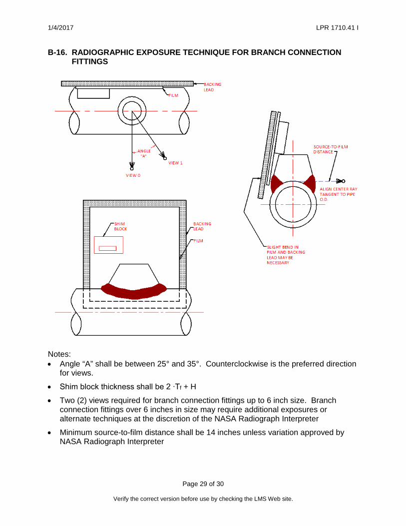
B-16. RADIOGRAPHIC EXPOSURE TECHNIQUE FOR BRANCH CONNECTION FITTINGS
Notes: • Angle “A” shall be between 25° and 35°. Counterclockwise is the preferred direction
for views.
• Shim block thickness shall be 2 ∙Tf + H
• Two (2) views required for branch connection fittings up to 6 inch size. Branch connection fittings over 6 inches in size may require additional exposures or alternate techniques at the discretion of the NASA Radiograph Interpreter
• Minimum source-to-film distance shall be 14 inches unless variation approved by NASA Radiograph Interpreter
1/4/2017 LPR 1710.41 I
Page 30 of 30
Verify the correct version before use by checking the LMS Web site.
B-17. INCOMPLETE PENETRATION IN BRANCH CONNECTION FITTINGS
All incomplete penetration is unacceptable.