Langley LPR 1710.40 N Procedural Requirements Expiration ... · Fire protection water systems for...
67
Page 1 of 67 Verify the correct version before use by checking the LMS Web site. Langley Procedural Requirements LPR 1710.40 N Effective Date: August 27, 2019 Expiration Date: August 27, 2024 Subject: Langley Research Center Pressure Systems Handbook Responsible Office: Safety and Mission Assurance Office TABLE OF CONTENTS PREFACE ..................................................................................................................... 3 1. PURPOSE, APPLICABILITY, AND EXCLUSIONS ............................................. 6 2. GENERAL REQUIREMENTS ............................................................................ 12 3. APPROVALS ..................................................................................................... 14 4. WAIVERS AND INTERPRETATIONS ............................................................... 15 5. DESIGN OF NEW PRESSURE SYSTEMS (GROUND-BASED) ....................... 16 6. FABRICATION OF NEW PRESSURE SYSTEMS (GROUND-BASED) ............ 18 7. MODIFICATIONS AND REPAIRS TO PRESSURE SYSTEMS (GROUND- BASED) .............................................................................................................. 19 8. PROCUREMENT OF PRESSURE SYSTEMS (GROUND-BASED) .................. 20 9. DESIGN, FABRICATION, AND PROCUREMENT OF FLIGHT-GRADE PRESSURE SYSTEMS ...................................................................................... 22 10. INSPECTION AND TESTING OF PRESSURE SYSTEMS (GROUND-BASED)23 11. VERIFICATION AND SHAKEDOWN OF PRESSURE SYSTEMS (GROUND- BASED) .............................................................................................................. 26 12. CERTIFICATION AND RECERTIFICATION OF PRESSURE SYSTEMS (GROUND-BASED) ............................................................................................ 28 13. OPERATIONS AND MAINTENANCE OF PRESSURE SYSTEMS (GROUND- BASED) .............................................................................................................. 29 14. DOCUMENTATION AND CONFIGURATION CONTROL OF PRESSURE SYSTEMS .......................................................................................................... 31 15. SUPPLEMENTAL REQUIREMENTS APPLICABLE TO SYSTEMS AND COMPONENTS .................................................................................................. 32 16. RESPONSIBILITIES .......................................................................................... 42 APPENDIX A. DEFINITIONS...................................................................................... 46
Transcript of Langley LPR 1710.40 N Procedural Requirements Expiration ... · Fire protection water systems for...

Page 1 of 67
Verify the correct version before use by checking the LMS Web site.
Langley
Procedural
Requirements
LPR 1710.40 N
Effective Date: August 27, 2019
Expiration Date: August 27, 2024
Subject: Langley Research Center Pressure Systems Handbook
Responsible Office: Safety and Mission Assurance Office
TABLE OF CONTENTS
PREFACE ..................................................................................................................... 3
1. PURPOSE, APPLICABILITY, AND EXCLUSIONS ............................................. 6
2. GENERAL REQUIREMENTS ............................................................................ 12
3. APPROVALS ..................................................................................................... 14
4. WAIVERS AND INTERPRETATIONS ............................................................... 15
5. DESIGN OF NEW PRESSURE SYSTEMS (GROUND-BASED) ....................... 16
6. FABRICATION OF NEW PRESSURE SYSTEMS (GROUND-BASED) ............ 18
7. MODIFICATIONS AND REPAIRS TO PRESSURE SYSTEMS (GROUND-BASED) .............................................................................................................. 19
8. PROCUREMENT OF PRESSURE SYSTEMS (GROUND-BASED) .................. 20
9. DESIGN, FABRICATION, AND PROCUREMENT OF FLIGHT-GRADE PRESSURE SYSTEMS ...................................................................................... 22
10. INSPECTION AND TESTING OF PRESSURE SYSTEMS (GROUND-BASED)23
11. VERIFICATION AND SHAKEDOWN OF PRESSURE SYSTEMS (GROUND-BASED) .............................................................................................................. 26
12. CERTIFICATION AND RECERTIFICATION OF PRESSURE SYSTEMS (GROUND-BASED) ............................................................................................ 28
13. OPERATIONS AND MAINTENANCE OF PRESSURE SYSTEMS (GROUND-BASED) .............................................................................................................. 29
14. DOCUMENTATION AND CONFIGURATION CONTROL OF PRESSURE SYSTEMS .......................................................................................................... 31
15. SUPPLEMENTAL REQUIREMENTS APPLICABLE TO SYSTEMS AND COMPONENTS .................................................................................................. 32
16. RESPONSIBILITIES .......................................................................................... 42
APPENDIX A. DEFINITIONS ...................................................................................... 46

August 27, 2019 LPR 1710.40 N
Page 2 of 67
Verify the correct version before use by checking the LMS Web site.
APPENDIX B. ABBREVIATIONS AND ACRONYMS ................................................ 49
APPENDIX C. BEST PRACTICES FOR PRESSURE SYSTEM DESIGN, INSTALLATION, AND OPERATION ................................................................. 52
APPENDIX D. PRESSURE RATING OF METALLIC SEAMLESS PIPING ............... 55
APPENDIX E. PRESSURE RATING OF METALLIC SEAMLESS TUBING .............. 62
APPENDIX F. RECOMMENDED PRACTICE FOR THE ESTABLISHMENT OF HAZARD PERIMETERS FOR PNEUMATIC TESTING ..................................... 65

August 27, 2019 LPR 1710.40 N
Page 3 of 67
Verify the correct version before use by checking the LMS Web site.
PREFACE
P. 1 PURPOSE
This Langley Procedural Requirement (LPR) implements the requirements of NASA Policy Directive (NPD) 8710.5, “Policy for Pressure Vessels and Pressurized Systems,” and is part of the Langley Management System (LMS). It establishes requirements and standards for pressurized systems within the framework of Langley Research Center (LaRC) safety policies and constraints. It provides a basis for safety and uniformity in the design, procurement, fabrication, and use of pressure vessels, piping, and associated equipment.
P.2 APPLICABILITY
a. This LPR is applicable to all persons performing work at LaRC, including civil service personnel, contractors and subcontractors, research associates, and others. Non-compliance with this LPR may result in appropriate disciplinary action that may include termination for a civil servant employee or exclusion from the Center for a contractor employee, research associate or others.
b. In this directive, all mandatory actions (i.e., requirements) are denoted by statements containing the term “shall.” The terms: “may” or “can” denote discretionary privilege or permission, “should” denotes a good practice and is recommended, but not required, “will” denotes expected outcome, and “are/is” denotes descriptive material.
c. All document citations are assumed to be the latest version unless otherwise noted.
P.3 AUTHORITY
a. NASA Policy Directive (NPD) 8710.5, Policy for Pressure Vessels and Pressurized Systems.
P.4 APPLICABLE DOCUMENTS AND FORMS
a. Aeronautics and Space, CFR Title 14.
b. Continuing Qualification and Maintenance of Packagings, 49 CFR pt. 180.
c. Ocupational Safety and Health Standards, 29 CFR pt. 1910.
d. NASA Procedural Requirements (NPR) 8715.3, NASA General Safety Program Requirements.
e. Langley Policy Directive (LAPD) 1150.2, Councils, Boards, Panels, Committees, Teams, and Groups.
f. LAPD 7000.2, Review Program for Langley Research Center (LaRC) Facility Projects.

August 27, 2019 LPR 1710.40 N
Page 4 of 67
Verify the correct version before use by checking the LMS Web site.
g. LAPD 8730.1, The LaRC Metrology Program.
h. LPR 1710.10, Langley Research Center Energy Control Program (Lockout/Tagout).
i. LPR 1710.11, Fire Protection Program.
j. LPR 1710.15, Wind-Tunnel Model Systems Criteria.
k. LPR 1710.41, Langley Research Center Standard for the Evaluation of Socket and Branch Connection Welds.
l. LPR 1710.42, Safety Program for the Recertification and Maintenance of Ground-Based Pressure Vessels and Piping Systems (PVS).
m. LPR 1740.2, Facility Safety Requirements.
n. LPR 1740.4, Facility System Safety Analysis.
o. LPR 1740.5, Procedures for Cleaning of Systems and Equipment for Oxygen Service.
p. LPR 1740.6, Personnel Safety Certificaiton.
q. LPR 2710.1, Langley Research Center Noise Control and Hearing Conservation Program.
r. LPR 7123.2, Facility Configuration Management.
s. Langley Management System Center Procedure (LMS-CP) 4710, Facility Change Request Process.
t. LMS-CP-5616, Computerized Maintenance Management System (CMMS) Change Request.
u. LMS-CP-7151, Obtaining Waivers for Langley Management System (LMS) Requirements.
v. NASA Technical Standard (STD) 8719.17, NASA Requirements for Ground-Based Pressure Vessels and Pressurized Systems (PVS).
w. LMS-BP-5688, Facility Systems Engineering Requirements Document Development.
x. LMS-Task Description (TD) 5569, Performing Visual Inspections.
y. Langley Form (LF) 51, Waiver Submittal Form.
z. LF 121, LaRC Safety Documentation Review for Certified Operators.
aa. LF 122, Facility Safety Awareness and Procedures Review for Certified Operators.
bb. LF 159, Appointment for Operator Certification.
cc. LF 461, Environmental Project Planning Form.
dd. LF 533, Safety Permit – Pressurized Systems.

August 27, 2019 LPR 1710.40 N
Page 5 of 67
Verify the correct version before use by checking the LMS Web site.
ee. American Institute of Aeronautics and Astonautics (AIAA) S-080, Space Systems – Metallic Pressure Vessels, Pressurized Structures, and Pressure Components.
ff. AIAA S-081, Space Systems – Composite Overwrapped Pressure Vessels. gg. American Petroleum Institute (API) Recommended Practice (RP) 521, Guide for
Pressure-Relieving and Depressuring Systems. hh. ASME B1.20.1, Pipe Threads, General Purpose (Inch). ii. ASME B16.11, Forged Fittings, Socket-Welding and Threaded. jj. ASME B31.1, Power Piping. kk. ASME B31.3, Process Piping. ll. ASME B31.5, Refrigeration Piping and Heat Transfer Components. mm. American Society of Mechanical Engineers (ASME), Boiler and Pressure Vessel
Code. nn. ASTM B88, Standard Specification for Seamless Copper Water Tube. oo. ASTM B280, Standard Specificaiton for Seamless Copper Tube for Aid
Conditioning and Refrigeration Field Service. pp. FM Global, Factory Mutual (FM) Global Property Loss Prevention Data Sheets,
(https://www.fmglobal.com/research-and-resources/fm-global-data-sheets). qq. International Code Council (ICC), International Mechanical Code. rr. National Board of Boiler and Pressure Vessel Inspectors (NBBI), NB-23, National
Board Inspection Code. ss. National Fire Protection Association (NFPA) 30, Flammable and Combustible
Liquids Code. tt. NFPA 54, National Fuel Gas Code. uu. NFPA 58, Liquefied Petroleum Gas Code. vv. SAE AMS5075, Steel Tubing, Seamless 0.22 – 0.28C (SAE 1025) Cold Drawn
and Stress Relieved.
P.5 MEASUREMENT/VERIFICATION
None
P.6 CANCELLATION
LPR 1710.40 L, Langley Research Center Pressure Systems Handbook, dated April 26, 2017.
/s/ Clayton P. Turner, Center Deputy Director April 26, 2017
Distribution:
Approved for public release via the Langley Management System; distribution is unlimited.

August 27, 2019 LPR 1710.40 N
Page 6 of 67
Verify the correct version before use by checking the LMS Web site.
1. PURPOSE, APPLICABILITY, AND EXCLUSIONS
Purpose
This LPR establishes requirements and guidelines regarding the design, procurement, fabrication, modification, repair, operation, and/or recertification of pressure systems owned by Langely Research Center (LaRC), whether located on Center or off Center, and of pressure systems owned by others that are used at LaRC.
This document is written on the premise that the functions and responsibilities listed in Chapter 16 are essential to provide the checks and balances indispensable to ensure pressure system safety.
Applicability
This LPR is applicable to all pressure systems owned by or used at LaRC, including new, existing, temporary, and permanent systems.
Pressurized systems in wind tunnel models shall be approved by the Standard Practice Engineer (SPE) for Wind Tunnel Models and will also comply with LPR 1710.15.
Ground-based pressurized systems in LaRC facilities shall also comply with LPR 1740.4 and LPR 7123.2.
Exclusions
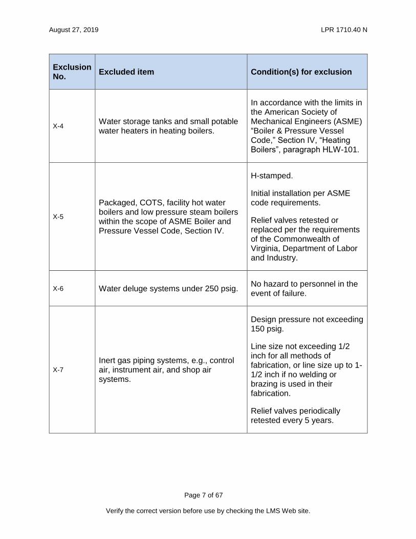
The categories of pressure systems listed in Table 1-A below are not required to meet the requirements of this LPR if they meet the specified conditions for exclusion.
Table 1-A, Excluded Systems
Exclusion No.
Excluded item Condition(s) for exclusion
X-1 Self-Contained Breathing Apparatus (SCBA) equipment.
Complies with Occupational Safety and Health Administration (OSHA) regulations, 29 Code of Federal Regulation (CFR) Part 1910, Subparts 1910.134 through 1910.140.
X-2 Water piping systems under 160 psig and 210 °F.
Water surge is not a design consideration or the risk has been mitigated.
X-3 Commercial-Off-The-Shelf (COTS) water heaters for buildings.
Pressure-temperature relief valves replaced every 5 years.
August 27, 2019 LPR 1710.40 N
Page 7 of 67
Verify the correct version before use by checking the LMS Web site.
Exclusion No.
Excluded item Condition(s) for exclusion
X-4 Water storage tanks and small potable water heaters in heating boilers.
In accordance with the limits in the American Society of Mechanical Engineers (ASME) “Boiler & Pressure Vessel Code,” Section IV, “Heating Boilers”, paragraph HLW-101.
X-5
Packaged, COTS, facility hot water boilers and low pressure steam boilers within the scope of ASME Boiler and Pressure Vessel Code, Section IV.
H-stamped.
Initial installation per ASME code requirements.
Relief valves retested or replaced per the requirements of the Commonwealth of Virginia, Department of Labor and Industry.
X-6 Water deluge systems under 250 psig. No hazard to personnel in the event of failure.
X-7 Inert gas piping systems, e.g., control air, instrument air, and shop air systems.
Design pressure not exceeding 150 psig.
Line size not exceeding 1/2 inch for all methods of fabrication, or line size up to 1-1/2 inch if no welding or brazing is used in their fabrication.
Relief valves periodically retested every 5 years.

August 27, 2019 LPR 1710.40 N
Page 8 of 67
Verify the correct version before use by checking the LMS Web site.
Exclusion No.
Excluded item Condition(s) for exclusion
X-8 Steam and gravity-powered condensate return systems for building heating.
Operating pressures up to 15 psig.
If the excluded steam system is fed by a higher-pressure steam system, the first relief device following the pressure-reducing regulator shall be retested yearly.
X-9 COTS prepackaged pressurized water and steam cleaning systems.
Maintained and operated in accordance with the manufacturer’s recommendations.
X-10 Fire protection water systems for facilities.
None.
X-11 COTS prepackaged refrigerators, freezers, and Heating, Ventilation, and Air Conditioning (HVAC) equipment.
None.
X-12
Fire extinguishers, portable extinguishers, standpipe and hose systems, automatic sprinkler systems, fixed dry chemical extinguishing systems, carbon dioxide extinguishing systems, and halogenated extinguishing agent systems.
Complies with 29 CFR Part 1910, Subpart L, "Fire Protection.”
X-13 Glove boxes. None.
X-14 Fuel storage pressure systems. Meets applicable U.S. Department of Transportation (DOT) requirements.

August 27, 2019 LPR 1710.40 N
Page 9 of 67
Verify the correct version before use by checking the LMS Web site.
Exclusion No.
Excluded item Condition(s) for exclusion
X-15 COTS prepackaged hydraulic systems. None.
X-16 COTS welding equipment. None.
X-17 COTS laboratory equipment. Fluid delivery system shall have suitable overpressure protection.
X-18 Vacuum vessels.
Volumes not greater than 100 cubic feet.
Not connected to a positive-pressure fluid delivery system.
X-19 Vacuum piping.
Nominal diameter of less than 6 inches.
Not connected to a positive-pressure fluid delivery system.
X-20 Contractor-owned pressure systems.
Used on a temporary basis for the purpose of construction activities.
The owning Contractor shall meet all applicable Federal and State safety regulations.
X-21 Atmospheric storage tanks.
Subjected to hydrostatic pressure only.
Complies with applicable American Petroleum Institute (API) or Underwriters Laboratories (UL) standards.

August 27, 2019 LPR 1710.40 N
Page 10 of 67
Verify the correct version before use by checking the LMS Web site.
Exclusion No.
Excluded item Condition(s) for exclusion
X-22 COTS self-contained pressurized eye wash systems
Overpressure protection devices, if present, are periodically tested or replaced in accordance with manufacturers’ recommendations.
X-23 Tube trailers.
Periodically retested and requalified in accordance with 49 CFR 180, provided that the owner’s OSHA inspection requirements of 29 CFR 1910.101 are met.
X-24 Natural gas distribution systems. Design pressure not exceeding 15 psig.
X-25 Pressurized test articles or test articles containing pressurized components.
Excluded if they have been reviewed and accepted by a formal safety review committee (see LAPD 1150.2) or by a formal Operational Readiness Review (ORR) board (see LAPD 7000.2).

August 27, 2019 LPR 1710.40 N
Page 11 of 67
Verify the correct version before use by checking the LMS Web site.
Exclusion No.
Excluded item Condition(s) for exclusion
X-26 Temporary, test-specific pressure systems.
Excluded if risk assessment in accordance with LPR 1740.4 shows there is no risk to personnel, and any unmitigated risk to the facility has been accepted by the Organizational Director.
Pressurized systems and components are not considered to fall into this category if they are used repeatedly for testing different test articles or configurations.
Note: For additional guidance on lockout/tagout procedures for pressure vessels listed in Table 1-A, see LPR 1710.10.

August 27, 2019 LPR 1710.40 N
Page 12 of 67
Verify the correct version before use by checking the LMS Web site.
2. GENERAL REQUIREMENTS
Required Codes and Standards
Pressure systems and components owned by or used at LaRC shall be designed, fabricated, modified, repaired, and/or recertified, as a minimum, in accordance with the following codes and standards as applicable:
a. American Institute of Aeronautics and Astronautics (AIAA)
(1) S-080, Space Systems – Metallic Pressure Vessels, Pressurized Structures, and Pressure Components
(2) S-081, Space Systems – Composite Overwrapped Pressure Vessels
b. American Society of Mechanical Engineers (ASME)
(1) Boiler and Pressure Vessel Code
(2) B31.1, Power Piping
Note: for steam and condensate piping
(3) B31.3, Process Piping
Note: for all piping other than steam and condensate
(4) B31.5, Refrigeration Piping and Heat Transfer Components
c. FM Global, Factory Mutual (FM) Data Sheets
Note: Applicable pressure equipment codes and standards in FM data sheet series 12.
d. International Code Council (ICC), International Mechanical Code
e. Langley Research Center
(1) LPR 1710.41, Langley Research Center Standard for the Evaluation of Socket and Branch Connection Welds
(2) LPR 1710.42, Safety Program for the Recertification and Maintenance of Ground-Based Pressure Vessels and Piping Systems (PVS)
(3) LPR 1710.15, Wind-Tunnel Model Systems Criteria
(4) LPR 1710.11, Fire Protection Program
(5) LPR 1740.4, Facility System Safety Analysis
(6) LPR 7123.2 Facility Configuration Management
f. NASA STD 8719.17, NASA Requirements for Ground-Based Pressure Vessels and Pressurized Systems (PVS)
g. National Board of Boiler and Pressure Vessel Inspectors (NBBI), NB-23, National Board Inspection Code
h. National Fire Protection Association (NFPA)
(1) NFPA 30, Flammable and Combustible Liquids Code

August 27, 2019 LPR 1710.40 N
Page 13 of 67
Verify the correct version before use by checking the LMS Web site.
(2) NFPA 54, National Fuel Gas Code
(3) NFPA 58, Liquefied Petroleum Gas Code

August 27, 2019 LPR 1710.40 N
Page 14 of 67
Verify the correct version before use by checking the LMS Web site.
3. APPROVALS
Required Approvals
All new designs, procurements, fabrications, modifications, and repairs to pressure systems and system components shall be approved by the following personnel:
a. The SPE for Pressure Systems or the SPE for Flight Systems, to ensure compliance with the required codes and standards.
b. The Facility Coordinator (FC), to ensure coordination with all activities in the facility where the pressure system is located.
c. The Facility Safety Head (FSH), to ensure compliance with specific safety requirements of the facility where the pressure system is located.
Additionally, the following signatures may be required, depending on the scope of the required work:
a. The Authority Having Jurisdiction (AHJ), to ensure compliance with required codes and regulations for pressure systems containing flammable or combustible liquids, flammable gases, cryogenic liquids, oxidizers, pyrophoric substances, highly reactive substances, or toxic substances.
b. The cognizant Safety and Facility Assurance Branch (SFAB) Safety Engineer, to ensure compliance with all applicable facility safety requirements.
c. The SPE for Welding, for pressure systems containing welded or brazed components, to ensure compliance with welding process quality assurance requirements, procedures, and codes.
Approval by the above listed personnel shall be verified by their signature and date on the design drawings, sketches, procurement requisition records, or work order functional approvals, as applicable.

August 27, 2019 LPR 1710.40 N
Page 15 of 67
Verify the correct version before use by checking the LMS Web site.
4. WAIVERS AND INTERPRETATIONS
Waivers
Approval for a waiver from the requirements in this LPR shall be obtained by following the process described in LMS-CP-7151, “Obtaining Waivers for LMS Requirements,” and as further described herein:
a. In the “Recommending Authorities” section of LF 51, the “Other Recommendation Authority” is the chairperson of the Pressure Systems Committee and the “Engineering Technical Authority” is the applicable SPE.
b. All requests for waivers from the requirements in this LPR, including requirements in any referenced Agency standards, national consensus codes, or industry standards, shall include full justification for the waiver request and supporting data or analyses to demonstrate that safe operation can be achieved.
Interpretations
The SPE for Pressure Systems, the SPE for Flight Systems, the SPE for Welding, and the AHJ are granted authority to issue interpretations on the applicability of individual requirements in this LPR within their respective areas of expertise.
August 27, 2019 LPR 1710.40 N
Page 16 of 67
Verify the correct version before use by checking the LMS Web site.
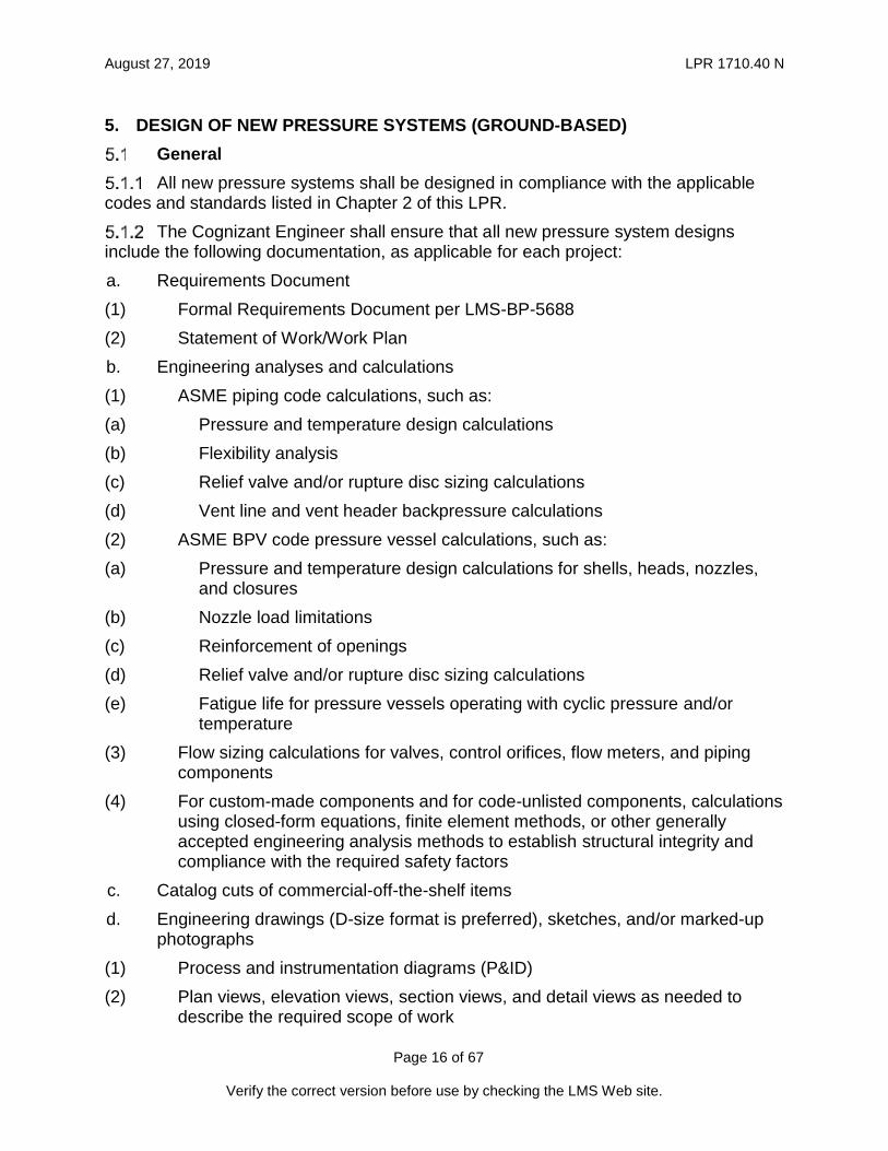
5. DESIGN OF NEW PRESSURE SYSTEMS (GROUND-BASED)
General
All new pressure systems shall be designed in compliance with the applicable codes and standards listed in Chapter 2 of this LPR.
The Cognizant Engineer shall ensure that all new pressure system designs include the following documentation, as applicable for each project:
a. Requirements Document
(1) Formal Requirements Document per LMS-BP-5688
(2) Statement of Work/Work Plan
b. Engineering analyses and calculations
(1) ASME piping code calculations, such as:
(a) Pressure and temperature design calculations
(b) Flexibility analysis
(c) Relief valve and/or rupture disc sizing calculations
(d) Vent line and vent header backpressure calculations
(2) ASME BPV code pressure vessel calculations, such as:
(a) Pressure and temperature design calculations for shells, heads, nozzles, and closures
(b) Nozzle load limitations
(c) Reinforcement of openings
(d) Relief valve and/or rupture disc sizing calculations
(e) Fatigue life for pressure vessels operating with cyclic pressure and/or temperature
(3) Flow sizing calculations for valves, control orifices, flow meters, and piping components
(4) For custom-made components and for code-unlisted components, calculations using closed-form equations, finite element methods, or other generally accepted engineering analysis methods to establish structural integrity and compliance with the required safety factors
c. Catalog cuts of commercial-off-the-shelf items
d. Engineering drawings (D-size format is preferred), sketches, and/or marked-up photographs
(1) Process and instrumentation diagrams (P&ID)
(2) Plan views, elevation views, section views, and detail views as needed to describe the required scope of work

August 27, 2019 LPR 1710.40 N
Page 17 of 67
Verify the correct version before use by checking the LMS Web site.
e. Parts lists and material specification tables
f. LF 461, Environmental Project Planning Form
g. Facility Change Request (FCR)
Design drawing packages and sketches shall include the following information:
a. Name of the Cognizant Engineer
b. Date
c. Facility name
d. Building number
e. Drawing or sketch title
f. Drawing or sketch number
g. Applicable design code(s) and/or standard(s)
h. Relevant engineering data, such as fluid service, design pressure, design temperature, material specification, non-destructive examination and inspection requirements, testing requirements, set pressure of relief devices, set points of all interlocks and protection devices, torque values of bolted connections, and requirements for welding and/or brazing.

August 27, 2019 LPR 1710.40 N
Page 18 of 67
Verify the correct version before use by checking the LMS Web site.
6. FABRICATION OF NEW PRESSURE SYSTEMS (GROUND-BASED)
General
New pressure systems shall be fabricated in accordance with an approved design as per Chapters 3 and 5 of this LPR.
The Cognizant Engineer shall supervise the progress of pressure system fabrication to ensure compliance with this LPR.
Pressure Vessels
Pressure vessels shall be stamped by the fabricator in accordance with the ASME Pressure Vessel Code, Section VIII, Divisions 1 or 2.
The fabricator shall provide a copy of the vessel’s code stamp documentation to NASA.
Piping Systems, Welded or Brazed
Welded or brazed piping systems shall be fabricated by organizations that are holders of an ASME (or National Board) Certificate of Authorization for the application of a code stamp, such as the “U”, “U2”, “N”, “R”, or “PP” stamps. The Certificate of Authorization ensures that the fabricator is familiar with and uses the quality control measures required by the ASME codes for pressure vessels and piping.
Whenever a pressure system is fabricated by welding or brazing, the fabricator shall submit the following documents for approval by the SPE for Welding or his/her designated representative prior to the start of any welding:
a. Welding or Brazing Procedure Specification (WPS/BPS)
b. Certified Procedure Qualification Records (PQR)
c. Certified Welder or Brazer Performance Qualifications (WPQ/BPQ)
All components installed in piping systems shall be permanently marked with legible raised lettering or stamping in order that required information (i.e., the manufacturer, pound class, model or part number, size, pressure rating, temperature rating, material of construction, and code of construction, as applicable) can be ascertained. Component markings can be limited to the manufacturer’s name or trademark and the manufacturer’s part number or model number if all other pertinent information as outlined above can be ascertained through the manufacturer’s catalogs or data sheets.
Piping Systems, Non-Welded or Non-Brazed
Non-welded or non-brazed piping and tubing systems shall be fabricated by persons that have received training in the specific fabrication methods utilized, who can demonstrate they understand proper material selection and the identification, installation, fit-up, alignment, and support of components to be used in such fabrications.

August 27, 2019 LPR 1710.40 N
Page 19 of 67
Verify the correct version before use by checking the LMS Web site.
7. MODIFICATIONS AND REPAIRS TO PRESSURE SYSTEMS (GROUND-BASED)
General
Pressure systems shall be modified or repaired in accordance with an approved design as defined in Chapters 3 and 5 of this LPR.
The Cognizant Engineer shall supervise the progress of pressure system modifications and repairs to ensure compliance with this LPR.
Pressure Vessels
Modifications and repairs to code-stamped pressure vessels shall be performed by organizations that are holders of a National Board Certificate of Authorization for use of an “R” stamp.
Modifications and repairs to non-code-stamped pressure vessels shall be performed by organizations that are holders of a National Board Certificate of Authorization for use of a “U”, “U2”, “R”, “N”, or “PP” stamp.
Piping Systems (Welded or Brazed)
Modifications and repairs to welded or brazed piping systems shall be performed by organizations that are holders of one of the following ASME or National Board stamps: “U”, “U2”, “R”, “N”, or “PP”.
Whenever a piping system is modified or repaired by welding or brazing, the fabricator shall submit the following documents for approval by the SPE for Welding or his/her designated representative prior to the start of any welding:
a. Welding or Brazing Procedure Specification (WPS/BPS)
b. Certified Procedure Qualification Records (PQR)
c. Certified Welder or Brazer Performance Qualifications (WPQ/BPQ)
Piping Systems (Non-Welded or Non-Brazed)
Modifications and repairs to non-welded or non-brazed piping and tubing systems shall be performed by persons who have received training in the specific fabrication methods utilized, who can demonstrate they understand proper material selection, and the identification, installation, fit-up, alignment, and support of components to be used in such fabrications.

August 27, 2019 LPR 1710.40 N
Page 20 of 67
Verify the correct version before use by checking the LMS Web site.
8. PROCUREMENT OF PRESSURE SYSTEMS (GROUND-BASED)
General
Procurements of pressure systems or of pressure system components shall be reviewed and approved as required in Chapter 3 of this LPR.
The requiring organization/customer is responsible for ensuring that the all required approvals outlined in Chapter 3 are complete, and shall coordinate with the approvers in Chapter 3 and the Office of Procurement to ensure the requirements under Chapter 8 are fulfilled and included in solicitation and resultant contractual documents.
Procurement of Pressure Vessels and Tanks
All procurements for COTS pressure vessels and tanks for use at LaRC shall require the vessels to be code stamped by a recognized U.S. national standards organization such as ASME, API, DOT, or UL, as applicable.
All contracts or purchase orders for the acquisition of new, custom-built pressure vessels shall:
a. Require the vessels to be ASME code stamped
b. Contain the following wording:
“This solicitation includes fabrication of pressure vessels. A current ASME Certificate of Authorization for use of a “U” or “U2” code stamp shall be held by the organization performing the fabrication and stamping of the pressure vessels. The contract award process will be expedited by submittal of the Certificate of Authorization with the offeror's bid; however, early certification submittal is not required to ensure bid responsiveness. An offeror’s ability to confirm that deliverable pressure vessels will be code stamped as required is a matter relating to the offeror’s responsibility and will be determined prior to award.”
All contracts or purchase orders for the acquisition of new, custom-built tanks shall require API or UL code stamping.
An approved waiver as described in Chapter 4 shall be obtained prior to procurement of non-code-stamped pressure vessels and tanks that are within the scope of this LPR.
The Cognizant Engineer shall require all Vendors supplying pressure vessels and tanks to furnish the following documents, as applicable:
a. Outline and Cross Sectional Drawings,
b. Bill of Materials,
c. ASME Code Calculations,
d. Welding Procedures (WPS),
e. Procedure Qualification Records (PQR),
f. Weld Maps,
g. Non-Destructive Examination (NDE) Records,
August 27, 2019 LPR 1710.40 N
Page 21 of 67
Verify the correct version before use by checking the LMS Web site.
h. Heat Treatment Records,
i. Hydrostatic Test Records,
j. Code Reports (ASME Code Forms, Manufacturer’s Data Reports, Nameplate Rubbing or Facsimile),
k. Charts (Hydrostatic Test, Post Weld Heat Treatment (PWHT)), and
l. Reports (Mill Test Report (MTR), Positive Material Identification (PMI), Non-destructive examination (NDE), Radiography, Hardness Test, Safety Data Sheet (SDS)).
Procurement of Piping Systems (Welded or Brazed)
All contracts requiring fabrication, modification, or repair of ground-based, welded or brazed piping systems shall:
a. Require the fabricator to be a holder of an ASME code stamp
b. Contain the following wording:
“This solicitation requires fabrication, modification, and/or repairs to pressure systems. A current National Board or ASME Certificate of Authorization for use of any of the following stamps: "R”, “U”, “U2”, “N”, or “PP” is required. This certificate shall be held by the organization performing the work and shall be maintained valid and current throughout the contract performance period. The contract award process will be expedited by submittal of the applicable Certificate of Authorization with the offeror’s bid; however, early certification submittal is not required to ensure bid responsiveness. An offeror’s ability to confirm that the organization performing the work is a holder of any of the above stamps is a matter relating to the offeror’s responsibility and will be determined prior to award.”

August 27, 2019 LPR 1710.40 N
Page 22 of 67
Verify the correct version before use by checking the LMS Web site.
9. DESIGN, FABRICATION, AND PROCUREMENT OF FLIGHT-GRADE PRESSURE SYSTEMS
Pressure Systems for Spacecraft
This section is applicable for all LaRC-owned pressure systems that are used in spacecraft or suborbital experiments.
All new pressure systems for spacecraft or suborbital experiments shall be compliant with ANSI/AIAA S-080, “Space Systems – Metallic Pressure Vessels, Pressurized Structures, and Pressure Components.”
All new composite overwrapped pressure vessels with metallic liners for spacecraft or suborbital experiments shall be compliant with ANSI/AIAA S-081, “Space Systems – Composite Overwrapped Pressure Vessels (COPVs).”
Pressure Systems for Aircraft and Lighter Than Air Vehicles
This section is applicable for all LaRC-owned pressure systems for experiments that are used in aircraft or lighter than air vehicles.
All new pressure systems for experiments on aircraft or lighter than air vehicles shall be compliant with FAA regulations for Airworthiness Standards in CFR Title 14, “Aeronautics and Space.”
All new pressure systems for experiments on aircraft or lighter than air vehicles can use ANSI/AIAA S-080, “Space Systems – Metallic Pressure Vessels, Pressurized Structures, and Pressure Components,” as an alternative to using CFR Title 14 Airworthiness Standards. If ANSI/AIAA S-080 is used in lieu of CFR Title 14 Airworthiness Standards, then full compliance with ANSI/AIAA S-080 is required.
Ground Support Pressure Systems for Flight-Grade Pressure Systems
All new ground support pressure systems for flight-grade pressure systems shall be considered ground-based pressure systems and be compliant with this LPR.
Operation of new ground support pressure systems for Flight-Grade pressure systems during operations and testing of the flight system shall be operated in accordance with ANSI/AIAA S-080.

August 27, 2019 LPR 1710.40 N
Page 23 of 67
Verify the correct version before use by checking the LMS Web site.
10. INSPECTION AND TESTING OF PRESSURE SYSTEMS (GROUND-BASED)
General
Minimum inspection and testing requirements for pressure systems shall be in accordance with the applicable design codes listed in Chapter 2 of this LPR.
The Cognizant Engineer shall ensure that the supplemental inspection and testing requirements in this Chapter are met.
Supplemental Inspection Requirements
In addition to the minimum requirements of the applicable codes and standards, the following requirements shall apply:
Table 10-A, LaRC Supplemental NDE Requirements
Joint Type
Butt Weld Socket Weld Branch Weld Fillet Weld
Threaded/Tubing
Pre
ssure
Vessels
Code Stamped
Per Code Requirements
Not Code
Stamped
100% VT 100% RT
100% VT 100% RT
100% VT 100% RT
100% VT 100% MT or
PT 100% VT
Pro
cess
Pip
ing
All 100% VT 100% RT
100% VT 100% RT
100% VT 100% RT
100% VT 100% MT or
PT 100% VT
Gas V
ent
Pip
ing
All 100% VT
10% MT or PT
100% VT 10% MT or
PT
100% VT 10% MT or
PT
100% VT 10% MT or
PT 100% VT
Liq
uid
Dra
in
Pip
ing
All 100% VT 100% VT 100% VT 100% VT 100% VT
MT = Magnetic Particle Examination; PT = Dye Penetration Examination; RT = Radiographic Examination; VT = Visual Testing
a. NDE in accordance with Table 10-A.
b. NDE shall be performed by inspectors certified to the American Society for Nondestructive Testing (ASNT) Level II or Level III requirements.
c. When heat treatment or stress relieving of a pressure retaining component is required, it shall been done after all welding, weld repairs, and required NDE are complete.

August 27, 2019 LPR 1710.40 N
Page 24 of 67
Verify the correct version before use by checking the LMS Web site.
(1) Additionally, an MT or PT examination of the heat-affected zone shall be conducted following the heat treatment but prior to the required hydrostatic test.
(2) All heat treated or stress relieved components or vessels shall be visibly marked with “Do Not Weld or Burn, Heat Treated.”
d. Inspection and acceptance criteria for socket welds and branch connection welds shall be in accordance with LPR 1710.41.
e. Acceptance criteria for butt welds in pressure systems shall be in accordance with ASME B31.3 for severe cyclic conditions.
f. For ground-based pressure system applications, film radiography shall be used.
g. Radiographic inspection of piping girth butt welds shall utilize tangential techniques wherever possible.
h. Final interpretation and acceptance of radiographs of pressure systems shall be by a qualified third party reviewer. The SPE for Pressure Systems is responsible for establishing the technical qualifications of the third party radiograph reviewers.
Note: NASA LaRC has an Official Radiograph Interpreter that can be used as the independent third party reviewer of radiographs.
(1) When film radiography is utilized in ground-based applications, all radiographic film shall be turned over to the SPE for Pressure Systems for final retention and storage.
(2) The radiographic film shall be retained in a controlled environment repository for a minimum of five years.
i. As a minimum, acceptance criteria for the evaluation of visual inspections of pressure components shall be in accordance with LMS-TD-5569.
j. Welds attaching structural elements to a pressure retaining wall shall be nondestructively examined as follows:
(1) The root pass and final weld surfaces shall be visually examined followed by either an MT or a PT examination.
(2) (2) The final weld surface shall be VT examined.
(3) Acceptance criteria shall be per ASME Boiler and Pressure Vessel (B&PV) Code Section VIII for attachments to pressure vessels and per ASME B31.3 (severe cyclic conditions) for attachments to piping.
Supplemental Hydrostatic and Pneumatic Testing Requirements
In addition to the minimum requirements for testing in the applicable codes, the Cognizant Engineer shall ensure that the following supplemental testing requirements are met:
a. Hydrostatic and pneumatic tests are used to qualify the structural integrity of new, modified, and repaired pressure systems. Both methods of testing are

August 27, 2019 LPR 1710.40 N
Page 25 of 67
Verify the correct version before use by checking the LMS Web site.
potentially hazardous. Adequate safety precautions shall be taken to ensure the safety of personnel and equipment.
b. Hydrostatic and pneumatic tests conducted in the field at LaRC shall be performed using written and approved test plans and operating procedures.
(1) A hydrostatic or pneumatic test plan shall include a drawing defining the extent of the system being tested; the location of high point vents and low point drains; test gauges to be used; water chloride content requirements; test blind rating requirements; test gasket requirements; and draining, drying, and closing requirements.
c. Pneumatic testing shall only be conducted when the appropriate SPE determines that hydrostatic testing is not feasible.
d. As a minimum, hydrostatic test plans shall be approved by the Cognizant Engineer and the appropriate SPE.
e. Pneumatic test procedures shall be approved by the FSH, the appropriate SPE, the Chairman of the Pressure Systems Committee, and the LaRC Safety Manager.
f. When performing pneumatic testing, a gas complying with cleanliness requirements of the pressure vessel and system shall be used.
g. A relief device of adequate capacity set to relieve at a pressure no higher than 110 percent of the test pressure shall be provided.
h. A hazard zone shall be established by engineering analysis as described in Appendix F.
i. All personnel shall be excluded from the hazard zone while the pressure exceeds the design pressure of the system being tested.
j. Appropriate personal protective equipment shall be worn by any personnel required to enter the hazard zone during the test.
k. Hydrostatic and pneumatic tests of pressure systems shall be witnessed by the appropriate SPE or his/her designated representative.
l. Following successful hydrostatic or pneumatic testing of vessels, piping, and tubing, a signed hydrostatic (or pneumatic) test certificate shall be provided by the fabricator or his or her testing agent.
m. The certificate shall include the date and time of the test, a short description of the tested system, the test pressure, holding time, and any other pertinent test parameters.
n. In the event that a required hydrostatic or pneumatic test is deemed to be impractical by the appropriate SPE, additional NDE shall be performed to ensure the structural integrity of the pressure system.
o. The SPE shall have the authority to establish the additional NDE requirements.

August 27, 2019 LPR 1710.40 N
Page 26 of 67
Verify the correct version before use by checking the LMS Web site.
11. VERIFICATION AND SHAKEDOWN OF PRESSURE SYSTEMS (GROUND-BASED)
General
All new, modified, or repaired pressure systems shall undergo verification and shakedown prior to being placed in operational service.
The Cognizant Engineer shall verify that the pressure system has been constructed, repaired, or modified in accordance with the approved design documents and that the system fabricator has provided all documentation to substantiate compliance with the requirements of the design.
Process for Verification
The Cognizant Engineer shall verify that:
a. All new work, modification work, or repair work has been completed in accordance with the engineering design, specifications, and drawings/sketches and complies with the requirements of thisLPR. Deviations from the original design, if any, were approved by the appropriate SPE.
b. All nondestructive examinations have been completed and accepted.
c. All hydrostatic tests, leak tests, and any other testing required by the design, repair, or modification documents have been completed and accepted.
d. All safety and interlock devices have current calibrations, have been installed, and are operating properly.
e. The operation of devices, e.g., valves, actuators, transmitters, switches, and gauges, has been properly verified prior to pressurizing the system.
f. Shakedown procedures as suitable for the complexity of the new system, modification, or repair have been developed and approved by the appropriate SPE and the FSH, or a formal design review committee. The appropriate SPE and FSH have the authority to require additional approvers by the appropriate personnel listed in Chapter 3 of this LPR.
g. A low pressure leak test has been performed on the system.
(1) If a leak test cannot be performed during the Return to Service (RTS) or Acceptance Test Plan (ATP), then an independent hazard analysis shall be performed and approved by the SPE for Pressure Systems and SFAB Safety Engineer.
h. For systems under configuration control, a Facility Change Request (FCR) has been initiated to update all affected documentation.
i. The system is ready to be pressurized as determined by the completion of the requirements above.
The Cognizant Engineer shall document completion of all the steps in the verification process listed in paragraph 11.2.1 through either:
a. Detailing the completion in a letter to the FSH and the appropriate SPE, or

August 27, 2019 LPR 1710.40 N
Page 27 of 67
Verify the correct version before use by checking the LMS Web site.
b. Completing and submitting an LF 438.
Process for Shakedown
Shakedown shall be performed after the system has been verified. The purpose of shakedown is to validate system performance, to provide an opportunity for operator training, and to develop standard operating procedures.
The Cognizant Engineer shall oversee shakedown. During shakedown:
a. Testing of the system operating envelope shall be conducted in accordance with approved shakedown procedures.
b. The operators shall be properly trained.
c. At the successful completion of training, the operators shall be certified in accordance with Chapter 13 of this LPR.
d. The operating procedures, if applicable, shall be completed and signed off in accordance with the facility configuration management process in LPR 7123.2.
e. The system performance shall be demonstrated with system fluids (systems containing toxic, combustible, flammable, or otherwise hazardous fluids shall use an inert fluid first).
f. For cryogenic systems, cold shock testing shall be performed to test the welds and flexibility of the piping and ensure that cold shock liquid does not contaminate the system.

August 27, 2019 LPR 1710.40 N
Page 28 of 67
Verify the correct version before use by checking the LMS Web site.
12. CERTIFICATION AND RECERTIFICATION OF PRESSURE SYSTEMS (GROUND-BASED)
Certification of New Systems
Based on the complexity of the new system and at the discretion of the LaRC Safety Manager, the operational certification of new pressure systems shall be performed by one of the following:
a. An Operational Readiness Review (ORR) board, or
b. The cognizant SPEs and Technical Authorities.
Recertification of Pressure Systems
The Pressure Systems Manager (PSM) is responsible for the recertification of pressure systems at LaRC.
Pressure systems shall be recertified in accordance with the requirements in LPR 1710.42 by using one of the following methods:
a. Level 1 recertification. This method is applicable to the majority of ground-based, infrastructure, high-energy systems.
b. Level 2 recertification. This abbreviated method is applicable to ground-based systems that are specifically exempted from full recertification by the PSM based on factors such as limited risk, minimum complexity, and similar factors.
c. Permit recertification. This method is primarily intended for research laboratories where a compressed gas cylinder (K-bottle) is connected to COTS laboratory equipment via a pressure regulator, relief device, and tubing system. It may also be used to certify temporary pressure system installations. Systems undergoing permit recertification are documented via a completed and approved LF 533.
d. D.O.T. recertification. This method is applicable to pressurized forged vessels mounted on transportable trailers (a.k.a., tube trailers) whether they are used in mobile or stationary applications.
e. Boiler recertification. This method is applicable to the steam boilers in the Central Heating and Steam Generation Plant, Building 1215.

August 27, 2019 LPR 1710.40 N
Page 29 of 67
Verify the correct version before use by checking the LMS Web site.
13. OPERATIONS AND MAINTENANCE OF PRESSURE SYSTEMS (GROUND-BASED)
General
Pressure systems under configuration control shall be operated in accordance with Standard Operating Procedures developed and approved in accordance with LPR 1740.4.
Facility Coordinators shall ensure that all pressure-retaining equipment (e.g., relief valves, control valves, gauges, transmitters) in pressure systems within their facility are included in the Computerized Maintenance Management System (CMMS) in accordance with LMS-CP-5616.
Pressure systems shall meet the requirements of NASA-STD-8719.17, LPR 1710.42, and this LPR to be certified for operation.
Operator Certification and Training
Pressure systems shall be run by system operators who have received training in the operational characteristics of the system and are knowledgeable of the operational procedures, checklists, inherent hazards, and operational limits associated with the system.
Operators of LaRC-owned pressure systems shall be certified in accordance with LPR 1740.6.
The FSH shall ensure that LF 121 and LF 122 include a suitable list of documents to ensure the operator has read and understands the operational procedures, checklists, inherent hazards, and operational limits associated with the system.
13.2.3.1 The certification of the operator shall be documented on LF 159.
13.2.3.2 The FSH shall ensure operator certifications are kept current.
The SFAB may periodically provide general pressure system awareness training that covers basic concepts, hazards, and engineering controls associated with pressure systems to interested Center organizations/personnel.
Operations and Maintenance Personnel Protection
When any servicing and/or maintenance operation could result in injury to personnel or serious damage to equipment due to the unexpected release of hazardous energy, the system shall be locked out/tagged out by a Safety Operator in accordance with LPR 1710.10.
The FSH shall ensure that the Safety Operator has met the qualifications in LPR 1710.10 to perform Lock Out/Tag Out (LOTO).
Any system containing toxic fluids, fuels, oxidizers, or other potentially dangerous media shall be purged in accordance with written procedures approved by the FSH.
13.3.3.1 The system shall be purged with an appropriate agent such as fresh air, water, inert gas, or a neutralizing agent, as appropriate, prior to initial use during a work

August 27, 2019 LPR 1710.40 N
Page 30 of 67
Verify the correct version before use by checking the LMS Web site.
shift, following last use during a work shift, and prior to disassembly or opening up the system.
Preventive Maintenance Requirements
Relief valves shall be included in LaRC’s Preventive Maintenance Program for retesting and verification in accordance with the frequencies specified in LPR 1710.42.
13.4.1.1 A log describing the maintenance work and test results on relief valves shall be kept at the Component Verification Facility.
Pressure sensing and indicating devices except for Category 1 and Category 2 devices subject to metrology requirements shall be included in LaRC’s Preventive Maintenance Program for retesting in accordance with the frequencies specified in paragraph 15.13 of this LPR. A log describing the maintenance work and test results on pressure sensing and indicating devices shall be kept at the Component Verification Facility.

August 27, 2019 LPR 1710.40 N
Page 31 of 67
Verify the correct version before use by checking the LMS Web site.
14. DOCUMENTATION AND CONFIGURATION CONTROL OF PRESSURE SYSTEMS
Required System Documentation
All ground-based infrastructure pressure systems shall be documented by means of:
a. A Process and Instrumentation Diagram (P&ID). The P&ID drawing shall identify all pressure sources, valves, vessels, drains, vents, flow direction, instrumentation, cleanliness level, and all safety devices and their set points.
b. A recertification file containing supporting documentation for the pressure system.
Updating Configuration Controlled Documents (CCD)
Whenever work activities result in changes to the configuration of a pressure system under configuration control, a Facility Change Request (FCR) form shall be initiated by the Cognizant Engineer after the approval of the design.
14.2.1.1 A FCR shall be initiated to update the system’s P&ID.
14.2.1.2 A separate FCR shall be initiated to update the Pressure Systems Document (PSD), if applicable.
Archiving and Retention of As-built Pressure Systems Documentation
Prior to completion of the construction of a new pressure system or completion of modifications to an existing pressure system, the Cognizant Engineer shall ensure that:
a. All new P&ID are field verified to show the final system configuration and are archived in Engineering Drawing Files.
b. Existing P&ID that are affected by the work are redlined to show modifications.
c. A copy of salient documentation such as construction drawings, design documents, calculations, catalog cuts, certification records, test reports, NDE records, material records, special welding procedures, and shakedown records are given to the Pressure Systems Recertification Group for archiving in the recertification file.
On-Site Documentation
As a minimum, the owner of a pressure system shall maintain at the facility a current copy of the following documents:
a. P&ID drawing.
b. Operations and Maintenance (O&M) manuals of the equipment in the system.
c. Certifications of calibrated devices and the frequency of the required calibrations.
August 27, 2019 LPR 1710.40 N
Page 32 of 67
Verify the correct version before use by checking the LMS Web site.
15. SUPPLEMENTAL REQUIREMENTS APPLICABLE TO SYSTEMS AND COMPONENTS
Anchoring of Components
All vessels and major components of a system shall be anchored to a stable foundation designed to withstand all static, dynamic, wind, and seismic loads acting on the pressure system.
Bushings (Single Step)
Hex-head pipe bushings of one-size reduction (single step) with dimensions conforming to ASME B16.11 shall not be used in pressure systems within the scope of this LPR.
Transitions requiring one-size reductions shall be made using concentric reducers, reducing couplings, or other fittings not having overlapping internal and external threads.
Cast Iron, Malleable Iron, and Ductile Iron
Pressure retaining components made of cast iron, malleable iron, or ductile iron shall not be used where they will be subject to vibration or shock loading.
Cleaning of Components
Pressurized components shall be cleaned internally before use to be compatible with their intended use. For example, proper cleaning of components to remove oils and other hydrocarbon-rich residues in systems containing oxygen gas, liquid oxygen, or high pressure air may be required to prevent the formation of flammable or explosive mixtures.
Systems containing oxygen and other systems requiring cleanliness to 10 parts per million or less of hydrocarbons, including systems that will be providing purge, pressurization, and test fluids to oxygen systems, shall be cleaned in accordance with LPR 1740.5.
Color Coding and Labeling
All pressure systems shall be labeled and color coded in accordance with LPR 1740.2 to properly identify the general hazard or risk level.
15.5.1.1 Whenever a pressure is included in the label, it shall be the normal operating pressure of the system.
CPV-Type Union Nuts
CPV-type unions 1-1/4" and larger in size shall not be used in compressed gas systems above 2400 psig.
CPV-type union nuts in systems operating above 2400 psig shall have vent holes drilled and be torqued to the values listed in Table 15-A.

August 27, 2019 LPR 1710.40 N
Page 33 of 67
Verify the correct version before use by checking the LMS Web site.
Table 15-A, CPV Nut Torques and Required Vent Hole Diameters
Size (IN.)
TORQUE (FT-LB)
VENT HOLE DIAMETER
(IN.)
1/8 10 - 25 1/16
¼ 10 – 25 1/16
3/8 12 – 30 1/16
1/2 15 – 40 3/32
3/4 20 – 50 3/32
1 25 – 60 3/32
Custom Filters and Filter Elements
Custom-built filters shall have the filter housing ASME code stamped with all welds 100 percent radiographically examined.
The vendor/supplier shall provide an ASME U-1A Form “Manufacturer’s Data Report” for each filter provided.
Filter-Regulators
Filter-regulators with see-through bowls shall not be used unless the bowl is made of impact-resistant glass or impact-resistant polycarbonate plastic.
Flexible Hoses
Flex hoses shall not be used in a system in lieu of rigid piping or tubing unless it is required for vibration isolation, motion allowance, component flexibility, or when the use of rigid piping or tubing has been determined by the appropriate SPE to be impractical.
Procurements of assembled flex hoses shall require the following:
a. The Maximum Allowable Working Pressure (MAWP) and the flex hose manufacturer’s name shall be marked on the outside of the hose.
b. When the procurement requires the manufacturer to conduct a pressure test on the flex hose prior to delivery, a signed pressure test certificate shall be supplied by the manufacturer.
c. If not tested by the manufacturer, the flex hose shall be tested by the Component Verification Facility prior to use.

August 27, 2019 LPR 1710.40 N
Page 34 of 67
Verify the correct version before use by checking the LMS Web site.
d. A tag shall be affixed to the flex hose indicating the date of the pressure test and the test pressure.
Flex hoses shall be restrained as follows:
a. Flex hoses with swaged end connections that could subject personnel to a whipping hazard in the event of failure of the end connections shall be fitted with anti-whip restraints and have sufficient intermediate restraint along their lengths to mitigate the hazard.
b. Flex hoses with welded or brazed end connections do not require anti-whip devices.
c. Flex hoses less than 2 feet in length do not require anti-whip restraints.
Flex hoses in liquid systems shall be evaluated by the appropriate SPE to determine anti-whip restraint requirements.
Prior to initial use, all flex hoses shall be hydrostatically tested to 150 percent of the maximum allowable working pressure stamped on the hose exterior.
No testing shall be performed on hoses lacking documentation, markings, or tags from the verification shop indicating the pressure rating of the hose.
Flex hoses shall be replaced every 5 years when:
a. The flex hose is fabricated with swaged ends and its rupture would cause unacceptable hazard to personnel or unacceptable risk to the facility or the mission.
b. The hose is exposed to agents or conditions that are known to deteriorate its inner or outer layers.
A pressure test tag or band shall be placed on all flex hoses indicating the date and pressure of the last test.
15.9.8.1 Flex hoses with missing test tags that are still traceable shall be retested to 150 percent of MAWP or replaced.
A flex hose, with leaks, flat areas, kinks, blisters, sharp ends, twists, damaged end fittings, cracks in the inner liner, severe corrosion (including the hose restraints), or has other signs of deterioration shall be removed from service and destroyed.
Flex hoses shall not be subjected to normal (or sustained) operating pressures greater than the manufacturer’s recommended MAWP.
15.9.10.1 Additionally, due to the probability of plastic yielding, any flex hose that experiences momentary pressures in excess of 2 times its MAWP shall be immediately removed from service and destroyed.
Gas Cylinders
Pressure systems using compressed gas cylinders as their source of fluid shall include adequately-sized pressure relieving devices on the downstream side of the pressure regulator.

August 27, 2019 LPR 1710.40 N
Page 35 of 67
Verify the correct version before use by checking the LMS Web site.
All components in the system upstream of the relief device shall be rated for the full pressure stamped on the gas bottle.
No consideration for reduced pressure in a partially full gas bottle shall be made to meet design requirements.
Note: Compressed gas cylinders are commonly referred to as “K bottles,” stemming from their D.O.T. designations, as follows in Table 15-B:
Table 15-B, Cylinder Types and Sizes
Cylinder Type
DOT Specification Volume
(ft3) Dimensions (H x diam.)
3K 3AA-3600 1.54 51” x 10”
4K E9421-4500 1.61 51” x 9.25”
6K 3AA-6000 1.50 51” x 10”
A typical sketch of a gas cylinder connection is shown in Figure 15-1.
Note: Figure 15-1 is included for informational purposes and does l not imply that other configurations are unacceptable at the discretion of the cognizant SPE.

August 27, 2019 LPR 1710.40 N
Page 36 of 67
Verify the correct version before use by checking the LMS Web site.
Figure 15-1, Basic design for connection of equipment to compressed gas bottles
Plastic tubing or rubber hose used to connect a gas cylinder to laboratory equipment shall have a maximum allowable working pressure equal to or higher than the relief valve setting.
Isolation & Depressurization
When a system is depressurized for the purpose of performing modifications, servicing, and/or maintenance operations, the procedures for locking and tagging out in LPR 1710.10 shall be followed.
Pressure gauges and pressure transmitters shall not be relied upon as the single means to verify a system is de-energized.
15.11.2.1 Depressurization of systems shall always be verified by the opening of vent valves or by other positive means.
Pressure Reducing Valves and Pressure Regulators
A pressure indicating device, whether a bourdon-tube gauge or a pressure transmitter, shall be installed on both the inlet and outlet sides of a pressure regulator or

August 27, 2019 LPR 1710.40 N
Page 37 of 67
Verify the correct version before use by checking the LMS Web site.
a pressure reducing valve to ensure proper monitoring of upstream and downstream pressures.
A pressure relief valve shall be installed on the downstream side of pressure reducing valves or pressure regulators unless all the components on the downstream side have a MAWP equal to or greater than the upstream side MAWP.
15.12.2.1 When a relief valve is required, it shall be installed as close as practical to the source of pressure without any intervening valves or closures.
Pressure Sensing and Indicating Devices
Table 15-C, Summary of Pressure Sensing Device Requirements
Bourdon tube gauges with safety case
Bourdon tube gauges lacking
safety case
Bourdon tube vacuum gauges
Pressure transmitters
and transducers
Pressure Switches
Allowable Working Range
0 – 80% of full scale
0 – 60% of full scale
0 – 100% of full scale
0 – 100% of full scale
0 – 100% of full scale
Test Pressure 100% of full
scale 100% of full
scale 100% of full
scale 100% of full
scale N / A
Type of Test (1) Dead Weight Dead Weight Vacuum pump Dead Weight Set point and
functional verification
Retest Period 5 years 5 years Per LPR 1740.4
5 years Per LPR 1740.4
Rejection Criteria (3)
EC, EW, ST, BG, SE
EC, EW, ST, BG, SE
EC, EW, ST, BG, SE
EC, EW, SE EC, EW, ST,
BG, SP
Test Label (2) Required Required Required if
tested Required Required
Notes for Table 15-C:
(1) Dead weight test media shall be water or oil. Oil shall not be used for gauges used with oxygen or other oxidizing agents. Oxygen-service pressure indicating devices undergoing verification shall be thoroughly dried then cleaned per LPR 1740.5 prior to returning to service.
(2) The test label shall include maximum test pressure, test date, and initials of testing personnel. (3) EC = excessive corrosion, EW = excessive wear, ST = sticktion, BG = broken glass, SE = span
error in excess of 5% of full scale, SP = setpoint error in excess of 3% of set value
In addition to the requirements in this LPR, pressure sensing and indicating devices identified as Category 1 or 2 Measurement and Test Equipment (M&TE) are subject to metrology requirements in LAPD 8730.1.
Differential pressure gauges shall be capable of withstanding full system differential pressure without failure.
A safety case shall include a solid front and a full-area blow out back.
August 27, 2019 LPR 1710.40 N
Page 38 of 67
Verify the correct version before use by checking the LMS Web site.
15.13.3.1 Blow out plugs shall not be considered sufficient to meet this requirement.
Note: See Figures 15-2 and 15-3 for examples of blow out plugs.
Bourdon-tube pressure gauges shall comply with applicable national consensus codes and the following additional requirements:
a. Gauges having a safety case shall have a maximum allowable working pressure of 80 percent of full scale.
b. Gauges lacking a safety case, except vacuum gauges, shall have a maximum allowable working pressure of 60 percent of full scale.
c. Panel mounting of bourdon-tube gauges shall allow the full-area blowout back to function properly.
Any bourdon-tube pressure sensing and indicating device that is subjected to pressures above 100 percent of its full scale range shall be immediately removed from service.
Pressure sensing and indicating devices that are critical interlocks shall be tested as required by LPR 1740.4 under the cognizance of the FSH.
Verification of pressure sensing and indicating devices shall be performed as follows:
a. Bourdon-tube pressure gauges shall be tested at the Component Verification Facility prior to initial installation and subsequently re-tested every 5 years to ensure proper operation.
b. Following verification, the tester shall keep a log that includes all pertinent test results, observations, the date of the test, and the device identifier listed in the CMMS.
15.13.7.1 Pressure sensing and indicating devices in excluded systems shall also be re-tested every 5 years if their reading is required in the system’s SOPs.
Criteria for rejection of pressure sensing and indicating devices that are not subject to metrology requirements shall be as follows:
a. Bourdon-tube gauges, pressure and vacuum – excessive corrosion or wear of the moving parts or of the pressure-retaining parts, sticktion, broken glass, and span error in excess of 5 percent of full scale.
b. Pressure transmitters and transducers – excessive corrosion or wear of the pressure-retaining parts and span error in excess of 5 percent of full scale.
c. Pressure switches – excessive corrosion or wear of the moving parts or of the pressure-retaining parts, sticktion, broken glass, and setpoint error in excess of 3 percent of set value.

August 27, 2019 LPR 1710.40 N
Page 39 of 67
Verify the correct version before use by checking the LMS Web site.
Figure 15-2, View of a bourdon-tube gauge with a solid front case and a full-area blow-out back
Figure 15-3, View of a bourdon tube gauge lacking a solid front case and having a
blow-out plug

August 27, 2019 LPR 1710.40 N
Page 40 of 67
Verify the correct version before use by checking the LMS Web site.
Pressure Relieving and Venting
Relief valves shall be ASME code stamped. The SPE for Pressure Systems has the authority to determine when the use of code stamped relief valves is impractical for a specific application.
When a single pressure relief device is used, the set pressure marked on the device shall not exceed the MAWP of the system being protected. When the total required capacity is provided by utilizing more than one pressure relief device, only one pressure relief device need be set at or below the maximum allowable working pressure. The additional pressure relief devices may be set to open at higher pressures but in no case at a pressure higher than 105 percent of the maximum allowable working pressure, except as provided in the applicable code.
Relief valves shall be periodically tested to check for proper operation and the accuracy of the set point.
15.14.3.1 Relief valves shall be properly tagged after testing. The maximum intervals for re-testing are listed in LPR 1710.42.
15.14.3.2 Relief valve tags shall include the valve number, set pressure, and the test date.
New relief valves shall be tested and certified by a National Board Valve Repair (VR) code stamp certified shop or by the LaRC Component Verification Facility prior to initial use to ensure proper relief setting.
A relief valve shall be used in parallel with a rupture diskdisc in cryogenic systems wherever liquid cryogen entrapment could occur.
Piping downstream of relief valves and vent valves shall:
a. Have a nominal diameter equal to or larger than the valve outlet size.
b. Be designed and routed such as to minimize exposure of personnel to vented media and to excessive noise levels as required in LPR 2710.1.
c. Incorporate means of reacting thrust loads, including the use of equalizing tees and structural supports.
d. Be designed for the MAWP of the system to which they are connected unless engineering calculations are made to justify a lower design pressure. For example, calculations may be performed in accordance with API RP-521, “Guide for Pressure-Relieving and Depressuring Systems.”
Seam-Welded Pipe and Tubing
Seam-welded pipe and tubing shall not be used in pressure systems.
Torque Values
Torque values for all bolted connections in pressure systems shall be designated on the system’s drawings.

August 27, 2019 LPR 1710.40 N
Page 41 of 67
Verify the correct version before use by checking the LMS Web site.
Langley Research Center Identification (LaRC ID) Locator Numbering
Permanently installed pressure system component locations at LaRC shall be numbered and tagged in accordance with Appendix E, “LaRC Location ID” of LPR 7123.2, “Facility Configuration Management,” and the additional requirements herein.
Personnel performing maintenance on a valve with a suffix listed in LPR 7123.2, or disassembling a system identified by this suffix, shall positively identify the system’s media before maintenance or disassembly operations begin.
In addition to the requirements listed in LPR 7123.2, the four digit valve number and the one digit media identifier (3142J in the example in Figure E-1 in LPR 7123.2) found on the valve tag shall be of at least ½ inch in height (36 point size) so as to be readable from a distance of 6 feet.
Viewports and Windows in Pressure Systems:
a. All viewports and windows in pressure and vacuum vessels shall be approved by the appropriate SPE.
b. A minimum safety factor of 10 shall be used for window designs.
c. Window frames shall be designed in accordance with the applicable code and will preclude metal contact with glass surfaces.

August 27, 2019 LPR 1710.40 N
Page 42 of 67
Verify the correct version before use by checking the LMS Web site.
16. RESPONSIBILITIES
The responsibilities listed below are essential to provide the checks and balances necessary to ensure pressure system safety.
The LaRC Center Director (or designee) is responsible for:
a. Granting waivers from the requirements of this LPR (Chapter 4).
The Cognizant Engineer is responsible for:
a. Ensuring that new pressure system designs include documentation to verify that the pressure systems are in accordance with the required codes and standards (Chapter 5).
b. Supervising the progress of the procurement, fabrication, modifications, or repairs to pressure systems (Chapters 6, 7, and 8).
c. Ensuring that pressure systems are inspected and tested in accordance with this
LPR (Chapter 10).
d. Performing or overseeing the performance of the verification process of pressure systems and certifying that new construction, modifications, or repairs are completed in accordance with this LPR (Chapter 11).
e. Performing or overseeing the performance of shakedown of pressure systems (Chapter 11).
f. Initiating a FCR to update all configuration controlled documentation of a pressure system (Chapter 11).
g. Ensuring that pressure system documentation is field verified, redlined, and filed following construction or installation work (Chapter 14).
The Director of Safety and Mission Assurance Office (SMAO) is responsible for:
a. Appointing an individual or individuals to serve as official radiographic interpreters for LaRC (Chapter 10).
b. Serving as “Accepter” in reviewing and signing requests for waivers, form LF 51 (Chapter 4).
Facility Coordinators are responsible for:
a. Reviewing and approving new designs, fabrication plans, modifications, and repairs to pressure systems in their facilities, as well as certifying that the pressure systems comply with facility requirements (Chapter 3).
b. Ensuring that all pressure-retaining equipment such as relief valves, control valves, gauges, and pressure transmitters in pressure systems within their facilities are included in the Computerized Maintenance Management System (CMMS) in accordance with LMS-CP-5616 (Chapter 13).
August 27, 2019 LPR 1710.40 N
Page 43 of 67
Verify the correct version before use by checking the LMS Web site.
Facility Safety Heads are responsible for:
a. Reviewing and approving new designs, fabrication plans, modifications, and repairs to pressure systems in their facilities, as well as certifying that the pressure systems comply with facility safety requirements (Chapter 3).
b. Approving pneumatic test procedures (Chapter 10).
c. Approving shakedown procedures (Chapter 11).
d. Ensuring that pressure system operators are properly trained and certified (Chapter 12).
e. Ensuring that Safety Operators performing LOTO at their facilities are certified in accordance with LPR 1710.10 (Chapter 13).
f. Approving procedures for purging pressure systems prior to the performance of service or maintenance activities (Chapter 13).
g. Ensuring that critical safety interlocks are tested as required by LPR 1740.4 (Chapter 15).
h. Approving blowdown procedures (Appendix C.4.1).
The AHJ is responsible for:
a. Reviewing and approving new designs, fabrication plans, modifications, and repairs to pressure systems containing flammable or combustible liquids, flammable gases, cryogenic liquids, oxidizers, pyrophoric substances, highly reactive substances, or toxic substances (Chapter 3).
b. Providing interpretation of the applicability requirements in this LPR related to code compliance in matters of fire protection, personnel safety, and the protection of LaRC assets (Chapter 4).
The LaRC Safety Manager is responsible for:
a. Approving pneumatic test procedures (Chapter 10).
b. Serving as member of the Operational Readiness Review (ORR) board that certifies new pressure systems for operation (Chapter 12).
c. Authorizing the appropriate SPE to perform the certification function of an ORR board (Chapter 12).
Owners of pressure systems are responsible for:
a. Serving as “Accepter” in reviewing and signing requests for waivers, form LF 51 (Chapter 4).
b. Ensuring duplicate valve numbers are not used in a pressure system (Chapter 15).
c. Keeping a current copy of all relevant pressure system documentation at the facility (Chapter 12).

August 27, 2019 LPR 1710.40 N
Page 44 of 67
Verify the correct version before use by checking the LMS Web site.
The chairman of the Pressure Systems Committee is responsible for:
a. Reviewing and approving pneumatic test procedures (Chapter 10).
b. Serving as “Recommending Authority” in reviewing and signing requests for waivers, form LF 51 (Chapter 4).
The Pressure Systems Manager is responsible for:
a. The recertification of pressure systems, as defined in LPR 1710.42.
Pressure Systems Operators are responsible for:
a. Reading and understanding the operational procedures and checklists of the pressure systems they work with (Chapter 13).
b. Understanding the inherent hazards of the pressure systems they work with and the engineering solutions and safety controls used to mitigate those hazards (Chapter 13).
c. Maintaining current certification in accordance with LPR 1740.6.
The Official Radiograph Interpreter is responsible for:
a. Serving as LaRC’s authority in the interpretation of radiographs of pressure system welds and signing for their final acceptance (Chapter 10).
Safety Operators are responsible for:
a. locking and tagging out a pressure system prior to the performance of any service or maintenance activity that could result in the unexpected release of hazardous energy from the system (Chapter 13).
The Standard Practice Engineer for Pressure Systems (ground-based) is responsible for:
a. Reviewing and approving new designs, fabrication plans, modifications, and repairs to pressure systems, certifying their compliance with required codes and standards (Chapter 3).
b. Providing interpretation of the applicability of the requirements of this LPR (Chapter 4).
c. Approving procurement of pressure systems and pressure system components (Chapter 8).
d. Establishing the required technical qualifications of the Official Radiograph Interpreters (Chapter 10).
e. Reviewing and approving plans for hydrostatic testing and for pneumatic testing (Chapter 10).
f. Witnessing hydrostatic and pneumatic tests (Chapter 10).
g. Establishing additional NDE required whenever hydrostatic testing or pneumatic testing is deemed impractical (Chapter 10).

August 27, 2019 LPR 1710.40 N
Page 45 of 67
Verify the correct version before use by checking the LMS Web site.
h. Reviewing and approving independent hazard analysis in lieu of low pressure leak tests (Chapter 10).
i. Reviewing and approving pressure system shakedown plans (Chapter 11).
j. Reviewing and approving changes to approved pressure system designs (Chapter 11).
k. Certifying new pressure systems for operation, in conjunction with the LaRC Safety Manager (Chapter 12).
l. Determining when the use of flexible hose in lieu of rigid piping is acceptable (Chapter 15).
m. Determining the need to restrain flexible hoses in systems containing pressurized liquids (Chapter 15).
n. Reviewing and approving the use of glass viewports in pressure systems (Chapter 15).
o. Approving blowdown procedures (Appendix C.4.1).
The responsibilities of the Standard Practice Engineer for Pressurized Flight Systems parallel those of the SPE for Pressure Systems, but as applicable to flight-grade systems.
The SPE for Welding is responsible for:
a. Reviewing and approving new designs, fabrication plans, modifications, and repairs to pressure systems, certifying their compliance with welding and quality assurance requirements (Chapter 3).
b. Providing interpretation of the applicability of the requirements of this LPR (Chapter 4).
c. Reviewing and approving welding documentation, i.e., WPS/BPS, PQR, and WPQ/BPQ (Chapters 6 and 7).
The SPE for Wind Tunnel Models is responsible for:
a. Reviewing and approving pressurized models to be tested in LaRC wind tunnels in accordance with LPR 1710.15 (Chapter 1).

August 27, 2019 LPR 1710.40 N
Page 46 of 67
Verify the correct version before use by checking the LMS Web site.
APPENDIX A. DEFINITIONS
Authority Having Jurisdiction (AHJ). An individual appointed by the Center Director to ensure regulatory and code compliance on matters involving the safety of personnel and protection of LaRC assets from fire hazards
Code stamp. A marking applied to a pressure component by a certified manufacturer to indicate compliance with a national consensus code. Available stamps include:
U – ASME B&PV Code Section VIII, Div 1 (Pressure Vessels)
U2 – ASME B&PV Code Section VIII, Div 2 (Pressure Vessels)
R – NBIC Pressure Vessel Repair
VR – NBIC Valve Repair
N – ASME B&PV Code Section III (Nuclear Facility Components)
PP – ASME Power Piping
Cognizant Engineer. The individual who is responsible for sponsoring, executing, or implementing the construction of a new pressure system or modifications to an existing pressure system. In this context, the word “engineer” is used to mean an individual with a degree in engineering or engineering technology, or an engineering technician with at least 5 years of experience in design, maintenance, or operations.
Commercial Off-The-Shelf Pressure Systems and Components. COTS pressure systems and components are systems and components routinely produced in quantity by an industrial manufacturer and adhere to one or more published national consensus standards or to manufacturer’s association standards. COTS pressure systems and components are typically furnished with a recommended pressure rating and temperature rating.
Critical interlock. An interlock that is designed specifically to mitigate an undesired event.
Design pressure. The maximum difference in pressure across the pressure retaining boundary of a pressurized component used in its design calculations.
Engineering Drawing Files. The electronic repository for LaRC drawings.
Excluded pressure system. A pressure system not required to meet the requirements of this LPR and NASA-STD-8719.17.
Facility Change Request. A FCR is an electronic form processed via the FCM website. A FCR is initiated to obtain approval for changes to systems under configuration control.
Facility Configuration Management. A LaRC website for processing FCRs or to obtain copies of Configuration Controlled Items (CCIs).
Inert gas. Refers to any non-reactive, non-toxic gaseous media, e.g., gaseous nitrogen, helium, and argon.
Interlock. A device (or devices) designed with the purpose of preventing a system from crossing a specified threshold or entering an undesirable mode of operation.

August 27, 2019 LPR 1710.40 N
Page 47 of 67
Verify the correct version before use by checking the LMS Web site.
Maximum Allowable Working Pressure (MAWP). The maximum pressure in a system, subsystem, or component as permitted by the applicable code. In general, the term “MAWP” is synonymous to the term “design pressure,” unless the MAWP is explicitly determined by calculations, testing, or recertification.
Maximum/minimum design temperature. The maximum/minimum metal temperature (averaged through-the-wall) considered in the design calculations.
Modification. An alteration or change to the original configuration of a pressure system, which may affect its pressure retaining capability. Any operational or physical change to a pressure system other than a direct replacement of a component is a modification. Operational changes may include such things as changing the normal operating pressure, temperature, or relief valve settings of the system. Physical changes may include such things as changing relief valves or adding/removing piping or components.
National Consensus Code. A document which (1) has been adopted or distributed by a nationally recognized standards developing organization using procedures such that it can be determined by the Secretary of Labor or by the Assistant Secretary of Labor for Occupational Safety and Health that persons interested and affected by the standard have reached substantial agreement on its adoption; (2) was formulated in a manner that afforded an opportunity for diverse views to be considered; and (3) has been so designated by the Secretary or the Assistant Secretary, after consultation with other appropriate Federal Agencies.
Normal operating pressure. The pressure in a piping system or pressure vessel under typical operating conditions.
Owner. The owner of a pressure system refers to the Organizational Director or his/her designated representative who is responsible for the pressure system.
Piping system. An assembly of structural components, which may include pipes, valves, fittings, and other such piping components, with the primary purpose to convey, distribute, mix, separate, discharge, meter, control, or snub the flow of a fluid. For the purpose of this definition, tubing and piping are considered to be interchangeable.
Pressure vessel. An assembly of structural components, which may include pipes, fittings, and piping components, with the primary purpose to hold, contain, or enclose a finite volume of a fluid under pressure or hold a vacuum.
Pressure system. A collection of piping systems and/or pressure vessels used jointly to convey or contain a pressurized fluid or a vacuum.
Pressure Systems Document. A configuration controlled document describing the current system configuration, including isometric sketches of the system and a database of components. PSDs are available through the FCM website.
Pressure Systems Manager. An individual responsible for managing the recertification program for pressure systems at LaRC
Relief device setting. The value of increasing inlet static pressure at which the relief device begins venting fluid. For different relief device types, this value may be called
August 27, 2019 LPR 1710.40 N
Page 48 of 67
Verify the correct version before use by checking the LMS Web site.
opening pressure, cracking pressure, popping pressure, start-to-leak pressure, burst pressure, or breaking pressure.
Repair. The work necessary to restore a pressure system to a safe and satisfactory operating condition, provided that no deviation from the original design is made.
SPE for Pressure Systems. An individual responsible for ensuring ground-based pressure systems at LaRC comply with this LPR.
SPE for Flight Systems. An individual responsible for ensuring pressure components on flight rated systems at LaRC comply with this LPR.
SPE for Welding. An individual responsible for ensuring that welding on pressure systems at LaRC complies with this LPR.
SPE for Wind Tunnel Models. An individual responsible for ensuring that wind tunnel models comply with LPR 1710.15 and this LPR as applicable.
Tank. A storage container intended to hold or store liquids, with low pressure gases or vapors in the space above the liquid surface.
Test article. An object being tested for the sole purpose of obtaining research data.
Test-Specific Pressure System. A pressure system used to perform research testing of a specific test article. Pressure systems used on a permanent basis or on a recurring basis are not considered to be test-specific. Pressure systems built up of components used repeatedly for testing different test articles or test configurations are not considered to be test-specific.

August 27, 2019 LPR 1710.40 N
Page 49 of 67
Verify the correct version before use by checking the LMS Web site.
APPENDIX B. ABBREVIATIONS AND ACRONYMS
AHJ Authority Having Jurisdiction
AIAA American Institute of Aeronautics and Astronautics
ANSI American National Standards Institute
API American Petroleum Institute
ASME American Society of Mechanical Engineers
ASNT American Society for Nondestructive Testing
ASTM American Society for Testing and Materials
B&PV Boiler and Pressure Vessel
BPQ Brazer Performance Qualifications
BPS Brazing Procedure Specification
CCD Configuration Controlled Document
CFR Code of Federal Regulations
CMMS Computerized Maintenance Management System
COTS Commercial Off The Shelf
CP Center Procedure
DOT U.S. Department of Transportation
FCM Facility Configuration Management
FCR Facility Change Request
FM Factory Mutual
FSH Facility Safety Head
HVAC Heating, Ventilation, and Air Conditioning
ICC International Code Council
LAPD Langley Policy Directive
LaRC Langley Research Center
LF Langley Form
LMS Langley Management System
LOTO Lock Out / Tag Out
LPR Langley Procedural Requirement

August 27, 2019 LPR 1710.40 N
Page 50 of 67
Verify the correct version before use by checking the LMS Web site.
M&TE Measurement and Test Equipment
MAWP Maximum Allowable Working Pressure
MT Magnetic particle examination
NASA National Aeronautics and Space Administration
NBIC National Board Inspection Code
NDE Non Destructive Examination
NPR NASA Procedural Requirements
OSHA Occupational Safety and Health Administration
O&M Operations & Maintenance
ORR Operational Readiness Review
P&ID Process and Instrumentation Diagram
PPE Personal Protective Equipment
PQR Procedure Qualification Record
PSD Pressure Systems Document
PSM Pressure Systems Manager
PSIG Pounds per square inch gauge
PSID Pounds per square inch differential
PT Dye penetrant examination
PVS Pressure Vessels and Pressurized Systems
RT Radiographic examination
RTS Return To Service
SAE Society of Automotive Engineers
SCBA Self-Contained Breathing Apparatus
SFAB Safety and Facility Assurance Branch
SMAO Safety and Mission Assurance Office
SPE Standard Practice Engineer
STD Standard
TD Task Description
UL Underwriters Laboratories

August 27, 2019 LPR 1710.40 N
Page 51 of 67
Verify the correct version before use by checking the LMS Web site.
VR Valve Repair stamp
VT Visual Testing
WPQ Welder Performance Qualifications
WPS Welding Procedure Specification

August 27, 2019 LPR 1710.40 N
Page 52 of 67
Verify the correct version before use by checking the LMS Web site.
APPENDIX C. BEST PRACTICES FOR PRESSURE SYSTEM DESIGN, INSTALLATION, AND OPERATION
C.1 Bladder Accumulators
C.1.1 Bladder accumulators should be pre-charged with nitrogen gas rather than air or other gases to prevent adverse reaction or combustion.
C.2 Deactivated Pressure Systems
C.2.1 When a pressure system is deactivated or placed in standby mode, it should be pressurized up to 25 psig with a dry, inert gas to prevent contamination and internal corrosion.
C.2.2 When a pressure system is abandoned in place, the piping should be completely removed when appropriate, or the piping where exposed should be left open or cut open and fully identified with tags or labels to indicate that the pipe is abandoned.
C.3 Double Block and Bleed Isolation
C.3.1 Isolation of sections of a pressure system for the purpose of performing maintenance or for performing work requiring opening the system to atmosphere should be accomplished utilizing a double-block and bleed valve configuration. See LPR 1710.10 for additional requirements for the use of double block and bleed valve configurations.
C.4 Drying of Pressure Systems
C.4.1 Following hydrostatic testing, internal surfaces in pressure systems should be dried using mechanical means, vacuum, or by blowdown with inert gas. If blowdown is to be performed, a written procedure should be developed and approved by the FSH and the SPE for Pressure Systems. As a minimum, the procedure should address the following hazards:
a. Noise,
b. High velocity air, water, and debris.
c. Movement due to unbalanced thrust at the discharge end,
d. Asphyxiation hazard if using an inert gas, and
e. Contamination of oxygen systems, where applicable.
C.5 Filters and Filter Elements
C.5.1 Filters should use ultrasonically-cleanable metallic filter elements whenever possible.
C.5.2 Filter elements should be designed to withstand full differential pressure without collapse. In the absence of this feature, the differential pressure across the filter element should be monitored to prevent collapse.
C.5.3 Whenever a filter housing contains threaded filter elements, the filter elements should be threaded into a removable tubesheet instead of threading directly into the filter housing. This is to prevent damage to the housing in the event the threads become

August 27, 2019 LPR 1710.40 N
Page 53 of 67
Verify the correct version before use by checking the LMS Web site.
galled or cross-threaded. Lifting lugs should be provided for removal of the elements/tubesheet.
C.5.4 Welds in filter elements should be VT examined and PT examined after fabrication. Criteria for rejection of filter element welds include (a) cracks in the weld area, (b) surface porosity, (c) excessive weld reinforcement, (d) undercut, and (e) lack of fusion.
C.5.5 The filter housing should allow for an annular area between the housing and the filter elements of at least 1.5 times the inlet piping cross sectional area.
C.5.6 The design of T-type filters should not produce direct flow impingement on the filter media.
C.5.7 Manufacturers of new custom-built filters should provide calculations of the filter element’s maximum allowable differential pressure, a certified as-built drawing of the filter housing, and a certified as-built drawing of the filter element and tubesheet, including part numbers.
C.6 Glass Windows in Pressure Systems
C.6.1 The use of glass windows exposed to pressure differentials should be avoided. If used, glass surfaces should be shielded or protected by quick-acting closures whenever possible. Indirect viewing using electronic cameras and monitors rather than direct viewing should be employed to the greatest extent possible.
C.6.2 Glass windows in pressure systems should not be subjected to extraneous heating or cooling sources such as ultraviolet lamps, infrared lamps, or other lighting/heat sources, cooling water or cryogenic gases, which could cause cracking and/or breakage due to thermal expansion of glass and/or frame.
C.6.3 Special consideration should be given to vacuum systems and implosion effects whereby viewing windows present potential hazards to personnel.
C.7 Normal Operating Pressure
C.7.1 The normal operating pressure of a system should be at least 10% below the relief device setting.
C.8 Pressure Relieving and Venting Systems
C.8.1 Piping downstream of relief valves and vent valves should be routed separately to the point of discharge. However, a common header that considers the effects of backpressure on the discharge capacity of the relief valves may be used when approved by the SPE for Pressure Systems.
C.8.2 Gas vent piping systems should be outfitted with screens at the point of discharge to keep out insects and animals.
C.9 Pressure Transmitters and Transducers
C.9.1 The use of pressure transmitters and pressure transducers in lieu of bourdon-tube pressure gauges should be used whenever there is a need to convey pressure data to facility control rooms.

August 27, 2019 LPR 1710.40 N
Page 54 of 67
Verify the correct version before use by checking the LMS Web site.
C.10 Reclaimed Materials
C.10.1 Reclaimed piping or tubing may be reused provided the reclaimed materials are:
a. Examined to determine if the minimum wall thickness is greater than that required by the applicable code.
b. Hydrostatically tested to 1.5 times the design pressure of the system.
c. Inspected for imperfections that would be unacceptable for its intended use.
d. Cleaned in sufficient measure to ensure compatibility with their intended use.
e. All welds in reused material should be 100% radiographically examined.
f. The material of the piping or tubing is ascertained through Positive Material
g. Identification (PMI) or material markings.
C.11 Supports
C.11.1 Piping and tubing should be firmly secured to a stable structure at or near mechanical joints and at bends to prevent violent displacement of the piping in event of joint failure.
C.12 Threaded Piping and Fittings
C.12.1 The use of threaded piping and fittings in nominal sizes greater than 1-1/2 inch is not recommended.
C.13 Valve Body Fabrication
C.13.1 Valves should be of forged construction for sizes 6 inches and larger where the flange rating is 600 pound class or above.
C.14 Valve Numbering
C.14.1 In building complexes where multiple research apparatus or facilities are fed from a common piping system, valves should not be assigned the same four digit valve number and suffix combination even if the three digit prefix is different. This is intended to facilitate proper valve identification when they are being serviced or operated.
C.14.2 When a valve is replaced, its valve number may be assigned to the replacement valve if the replacement valve performs the identical function as the original valve (system isolation, pressure control, flow control, venting, or pressure relief) and the replacement valve is in the same functional location as the original valve, as determined from the pressure system’s P&ID. If the above conditions are not met, the replacement valve should be assigned a new valve number. Example: a manually operated isolation valve is replaced by a pneumatically-operated control valve. In this example, the control valve should be assigned a new valve number.

August 27, 2019 LPR 1710.40 N
Page 55 of 67
Verify the correct version before use by checking the LMS Web site.
APPENDIX D. PRESSURE RATING OF METALLIC SEAMLESS PIPING
In accordance with ASME B31.3 – 2014
This table is valid for seamless piping with allowable stress value SE=20,000 psi at design temperature. Example materials include A-53 Grade B, A-106 Grade B and A-312 Grades TP304, TP316, and TP347.
WELDED (Note 1) THREADED (Note 1)
Nominal Pipe Size
Wall Schedule
Outside Diameter
Nominal Wall
Thickness
Max. Thread Depth
Allowable Pressure
(PSIG)
SW Fitting Pound Class
Allowable Pressure
(PSIG) Thr. Fitting Pound Class
1/8
10 0.405 0.049 (Note 6) 4641 3000#
30 0.405 0.057 0.02963 5479 3000# 2057 2000#
40 0.405 0.068 0.02963 6723 3000# 3150 2000#
STD 0.405 0.068 0.02963 6723 3000# 3150 2000#
80 0.405 0.095 0.02963 7525 3000# 5295 2000#
XS 0.405 0.095 0.02963 7525 3000# 5295 2000#
1/4
10 0.540 0.065 (Note 6) 4612 3000#
30 0.540 0.073 0.04444 5237 3000# 1448 2000#
40 0.540 0.088 0.04444 6438 3000# 2570 2000#
STD 0.540 0.088 0.04444 6438 3000# 2570 2000#
80 0.540 0.119 0.04444 7182 3000# 4561 2000#
XS 0.540 0.119 0.04444 7182 3000# 4561 2000#
3/8
10 0.675 0.065 (Note 6) 3622 3000#
30 0.675 0.073 0.04444 4104 3000# 1152 2000#
40 0.675 0.091 0.04444 5237 3000# 2164 2000#
STD 0.675 0.091 0.04444 5237 3000# 2164 2000#
80 0.675 0.126 0.04444 7496 3000# 4243 2000#
XS 0.675 0.126 0.04444 7496 3000# 4243 2000#
1/2
5 0.840 0.065 (Note 6) 2870 3000#
10 0.840 0.083 (Note 6) 3736 3000#
30 0.840 0.095 0.05714 4292 3000# 1270 2000#
40 0.840 0.109 0.05714 4974 3000# 1877 2000#
STD 0.840 0.109 0.05714 4974 3000# 1877 2000#
80 0.840 0.147 0.05714 7003 3000# 3626 2000#
XS 0.840 0.147 0.05714 7003 3000# 3626 2000#
160 0.840 0.188 0.05714 7240 6000# 5113 3000#
XXS 0.840 0.294 0.05714 9808 9000# 8378 6000#
3/4
5 1.050 0.065 (Note 6) 2270 3000#
10 1.050 0.083 (Note 6) 2945 3000#
30 1.050 0.095 0.05714 3375 3000# 1010 2000#
40 1.050 0.113 0.05714 4079 3000# 1653 2000#
STD 1.050 0.113 0.05714 4079 3000# 1653 2000#

August 27, 2019 LPR 1710.40 N
Page 56 of 67
Verify the correct version before use by checking the LMS Web site.
WELDED (Note 1) THREADED (Note 1)
Nominal Pipe Size
Wall Schedule
Outside Diameter
Nominal Wall
Thickness
Max. Thread Depth
Allowable Pressure
(PSIG)
SW Fitting Pound Class
Allowable Pressure
(PSIG) Thr. Fitting Pound Class
80 1.050 0.154 0.05714 5732 3000# 3159 2000#
XS 1.050 0.154 0.05714 5732 3000# 3159 2000#
160 1.050 0.219 0.05714 6887 6000# 5158 3000#
XXS 1.050 0.308 0.05714 8812 9000# 7455 6000#
1
5 1.315 0.065 (Note 6) 1796 3000#
10 1.315 0.109 (Note 7) 3067 3000#
30 1.315 0.114 0.06957 3239 3000# 930 2000#
40 1.315 0.133 0.06957 3796 3000# 1472 2000#
STD 1.315 0.133 0.06957 3796 3000# 1472 2000#
80 1.315 0.179 0.06957 5280 3000# 2794 2000#
XS 1.315 0.179 0.06957 5280 3000# 2794 2000#
160 1.315 0.250 0.06957 7686 6000# 4984 3000#
XXS 1.315 0.358 0.06957 8377 9000# 6969 6000#
1-1/4
5 1.660 0.065 (Note 6) 1412 3000#
10 1.660 0.109 (Note 6) 2399 3000#
30 1.660 0.117 0.06927 2585 3000# 808 2000#
40 1.660 0.140 0.06927 3151 3000# 1311 2000#
STD 1.660 0.140 0.06927 3151 3000# 1311 2000#
80 1.660 0.191 0.06927 4376 3000# 2479 2000#
XS 1.660 0.191 0.06927 4376 3000# 2479 2000#
160 1.660 0.250 0.06957 5900 6000# 3868 3000#
XXS 1.660 0.382 0.06957 7423 9000# 6186 6000#
1-1/2
5 1.900 0.065 (Note 6) 1230 3000#
10 1.900 0.109 (Note 6) 2083 3000#
30 1.900 0.125 0.06957 2405 3000# 857 2000#
40 1.900 0.145 0.06957 2825 3000# 1230 2000#
STD 1.900 0.145 0.06957 2825 3000# 1230 2000#
80 1.900 0.200 0.06957 3977 3000# 2313 2000#
XS 1.900 0.200 0.06957 3977 3000# 2313 2000#
160 1.900 0.281 0.06957 5777 6000# 4002 3000#
XXS 1.900 0.400 0.06957 6941 9000# 5812 6000#
2
5 2.375 0.065 (Note 6) 979 3000#
10 2.375 0.109 (Note 6) 1653 3000#
30 2.375 0.125 0.06957 1906 3000# 683 2000#
40 2.375 0.154 0.06957 2382 3000# 1119 2000#
STD 2.375 0.154 0.06957 2382 3000# 1119 2000#
80 2.375 0.218 0.06957 3438 3000# 2124 2000#
XS 2.375 0.218 0.06957 3438 3000# 2124 2000#

August 27, 2019 LPR 1710.40 N
Page 57 of 67
Verify the correct version before use by checking the LMS Web site.
WELDED (Note 1) THREADED (Note 1)
Nominal Pipe Size
Wall Schedule
Outside Diameter
Nominal Wall
Thickness
Max. Thread Depth
Allowable Pressure
(PSIG)
SW Fitting Pound Class
Allowable Pressure
(PSIG) Thr. Fitting Pound Class
160 2.375 0.344 0.06957 5641 6000# 4219 3000#
XXS 2.375 0.436 0.06957 7384 9000# 5872 6000#
2-1/2
5 2.875 0.083 (Note 6) 1037 3000#
10 2.875 0.120 (Note 6) 1505 3000#
30 2.875 0.188 0.1 2406 3000# 921 2000#
40 2.875 0.203 0.1 2606 3000# 1109 2000#
STD 2.875 0.203 0.1 2606 3000# 1109 2000#
80 2.875 0.276 0.1 3610 3000# 2057 2000#
XS 2.875 0.276 0.1 3610 3000# 2057 2000#
160 2.875 0.375 0.1 5022 (Note 3) 3387 3000#
XXS 2.875 0.552 0.1 6456 (Note 3) 5333 6000#
3
5 3.500 0.083 (Note 6) 848 3000#
10 3.500 0.120 (Note 6) 1230 3000#
30 3.500 0.188 0.1 1960 3000# 754 2000#
40 3.500 0.216 0.1 2258 3000# 1038 2000#
STD 3.500 0.216 0.1 2258 3000# 1038 2000#
80 3.500 0.300 0.1 3198 3000# 1923 2000#
XS 3.500 0.300 0.1 3198 3000# 1923 2000#
160 3.500 0.438 0.1 4797 (Note 3) 3458 3000#
XXS 3.500 0.600 0.1 6818 (Note 3) 5380 6000#
3-1/2
5 4.000 0.083 (Note 6) 741 3000#
10 4.000 0.120 (Note 6) 1073 3000#
30 4.000 0.188 0.1 1706 3000# 659 2000#
40 4.000 0.226 0.1 2062 3000# 1000 2000#
STD 4.000 0.226 0.1 2062 3000# 1000 2000#
80 4.000 0.318 0.1 2944 3000# 1846 2000#
XS 4.000 0.318 0.1 2944 3000# 1846 2000#
XXS 4.000 0.636 0.1 6256 (Note 3) 5030 6000#
4
5 4.500 0.083 (Note 6) 657 3000#
10 4.500 0.120 (Note 6) 951 3000#
30 4.500 0.188 0.1 1511 3000# 585 2000#
40 4.500 0.237 0.1 1910 3000# 970 2000#
STD 4.500 0.237 0.1 1910 3000# 970 2000#
80 4.500 0.337 0.1 2767 3000# 1796 2000#
XS 4.500 0.337 0.1 2767 3000# 1796 2000#
120 4.500 0.438 0.1 3653 (Note 2) 2649 2000#
160 4.500 0.531 0.1 4506 (Note 3) 3470 3000#
XXS 4.500 0.674 0.1 5859 (Note 3) 4771 6000#

August 27, 2019 LPR 1710.40 N
Page 58 of 67
Verify the correct version before use by checking the LMS Web site.
WELDED (Note 1) THREADED (Note 1)
Nominal Pipe Size
Wall Schedule
Outside Diameter
Nominal Wall
Thickness
Max. Thread Depth
Allowable Pressure
(PSIG)
SW Fitting Pound Class
Allowable Pressure
(PSIG) Thr. Fitting Pound Class
5
5 5.563 0.109 693 (Note 3) (Note 4)
10 5.563 0.134 856 (Note 3) (Note 4)
40 5.563 0.258 1680 (Note 3) (Note 4)
STD 5.563 0.258 1680 (Note 3) (Note 4)
80 5.563 0.375 2475 (Note 3) (Note 4)
XS 5.563 0.375 2475 (Note 3) (Note 4)
120 5.563 0.500 3361 (Note 3) (Note 4)
160 5.563 0.625 4269 (Note 3) (Note 4)
XXS 5.563 0.750 5208 (Note 3) (Note 4)
6
5 6.625 0.109 580 (Note 3) (Note 4)
10 6.625 0.134 717 (Note 3) (Note 4)
40 6.625 0.280 1524 (Note 3) (Note 4)
STD 6.625 0.280 1524 (Note 3) (Note 4)
80 6.625 0.432 2391 (Note 3) (Note 4)
XS 6.625 0.432 2391 (Note 3) (Note 4)
120 6.625 0.562 3158 (Note 3) (Note 4)
160 6.625 0.719 4110 (Note 3) (Note 4)
XXS 6.625 0.864 5023 (Note 3) (Note 4)
8
5 8.625 0.109 444 (Note 3) (Note 4)
10 8.625 0.148 610 (Note 3) (Note 4)
20 8.625 0.250 1037 (Note 3) (Note 4)
30 8.625 0.277 1148 (Note 3) (Note 4)
40 8.625 0.322 1343 (Note 3) (Note 4)
STD 8.625 0.322 1343 (Note 3) (Note 4)
60 8.625 0.406 1702 (Note 3) (Note 4)
80 8.625 0.50 2117 (Note 3) (Note 4)
XS 8.625 0.50 2117 (Note 3) (Note 4)
100 8.625 0.594 2534 (Note 3) (Note 4)
120 8.625 0.719 3098 (Note 3) (Note 4)
140 8.625 0.812 3530 (Note 3) (Note 4)
XXS 8.625 0.875 3824 (Note 3) (Note 4)
160 8.625 0.906 3970 (Note 3) (Note 4)
10
5 10.750 0.134 439 (Note 3) (Note 4)
10 10.750 0.165 542 (Note 3) (Note 4)
20 10.750 0.250 828 (Note 3) (Note 4)
30 10.750 0.307 1021 (Note 3) (Note 4)
40 10.750 0.365 1216 (Note 3) (Note 4)
10 STD 10.750 0.365 1216 (Note 3) (Note 4)

August 27, 2019 LPR 1710.40 N
Page 59 of 67
Verify the correct version before use by checking the LMS Web site.
WELDED (Note 1) THREADED (Note 1)
Nominal Pipe Size
Wall Schedule
Outside Diameter
Nominal Wall
Thickness
Max. Thread Depth
Allowable Pressure
(PSIG)
SW Fitting Pound Class
Allowable Pressure
(PSIG) Thr. Fitting Pound Class
60 10.750 0.50 1685 (Note 3) (Note 4)
XS 10.75 0.50 1685 (Note 3) (Note 4)
80 10.75 0.594 2013 (Note 3) (Note 4)
100 10.75 0.719 2455 (Note 3) (Note 4)
120 10.75 0.844 2906 (Note 3) (Note 4)
140 10.75 1.000 3483 (Note 3) (Note 4)
160 10.75 1.125 3951 (Note 3) (Note 4)
12
5 12.75 0.156 434 (Note 3) (Note 4)
10 12.75 0.180 501 (Note 3) (Note 4)
20 12.75 0.250 697 (Note 3) (Note 4)
30 12.75 0.330 923 (Note 3) (Note 4)
STD 12.75 0.375 1051 (Note 3) (Note 4)
40 12.75 0.406 1139 (Note 3) (Note 4)
XS 12.75 0.500 1413 (Note 3) (Note 4)
60 12.75 0.562 1593 (Note 3) (Note 4)
80 12.75 0.688 1963 (Note 3) (Note 4)
100 12.75 0.844 2428 (Note 3) (Note 4)
120 12.75 1.000 2905 (Note 3) (Note 4)
XXS 12.75 1.000 2905 (Note 3) (Note 4)
140 12.75 1.125 3290 (Note 3) (Note 4)
160 12.75 1.312 3881 (Note 3) (Note 4)
14
5 14 0.156 395 (Note 3) (Note 4)
10 14 0.250 634 (Note 3) (Note 4)
20 14 0.312 792 (Note 3) (Note 4)
30 14 0.375 955 (Note 3) (Note 4)
STD 14 0.375 955 (Note 3) (Note 4)
40 14 0.438 1119 (Note 3) (Note 4)
XS 14 0.500 1284 (Note 3) (Note 4)
60 14 0.594 1531 (Note 3) (Note 4)
80 14 0.750 1947 (Note 3) (Note 4)
100 14 0.938 2461 (Note 3) (Note 4)
120 14 1.094 2892 (Note 3) (Note 4)
140 14 1.250 3334 (Note 3) (Note 4)
160 14 1.406 3780 (Note 3) (Note 4)
16 5 16 0.165 363 (Note 3) (Note 4)
10 16 0.250 554 (Note 3) (Note 4)
16
20 16 0.312 692 (Note 3) (Note 4)
30 16 0.375 834 (Note 3) (Note 4)
STD 16 0.375 834 (Note 3) (Note 4)

August 27, 2019 LPR 1710.40 N
Page 60 of 67
Verify the correct version before use by checking the LMS Web site.
WELDED (Note 1) THREADED (Note 1)
Nominal Pipe Size
Wall Schedule
Outside Diameter
Nominal Wall
Thickness
Max. Thread Depth
Allowable Pressure
(PSIG)
SW Fitting Pound Class
Allowable Pressure
(PSIG) Thr. Fitting Pound Class
40 16 0.500 1120 (Note 3) (Note 4)
XS 16 0.500 1120 (Note 3) (Note 4)
60 16 0.656 1477 (Note 3) (Note 4)
80 16 0.844 1916 (Note 3) (Note 4)
100 16 1.031 2362 (Note 3) (Note 4)
120 16 1.219 2818 (Note 3) (Note 4)
140 16 1.438 3356 (Note 3) (Note 4)
160 16 1.594 3749 (Note 3) (Note 4)
18
5 18 0.165 322 (Note 3) (Note 4)
10 18 0.250 491 (Note 3) (Note 4)
20 18 0.312 614 (Note 3) (Note 4)
STD 18 0.375 740 (Note 3) (Note 4)
30 18 0.438 866 (Note 3) (Note 4)
XS 18 0.500 993 (Note 3) (Note 4)
40 18 0.562 1118 (Note 3) (Note 4)
60 18 0.750 1502 (Note 3) (Note 4)
80 18 0.938 1894 (Note 3) (Note 4)
100 18 1.156 2352 (Note 3) (Note 4)
120 18 1.375 2824 (Note 3) (Note 4)
160 18 1.781 3720 (Note 3) (Note 4)
20
5 20 0.188 332 (Note 3) (Note 4)
10 20 0.250 442 (Note 3) (Note 4)
20 20 0.375 665 (Note 3) (Note 4)
STD 20 0.375 665 (Note 3) (Note 4)
30 20 0.500 892 (Note 3) (Note 4)
XS 20 0.500 892 (Note 3) (Note 4)
40 20 0.594 1062 (Note 3) (Note 4)
60 20 0.812 1464 (Note 3) (Note 4)
80 20 1.031 1872 (Note 3) (Note 4)
100 20 1.281 2347 (Note 3) (Note 4)
120 20 1.500 2772 (Note 3) (Note 4)
140 20 1.750 3262 (Note 3) (Note 4)
160 20 1.969 3701 (Note 3) (Note 4)
22
5 22 0.188 302 (Note 3) (Note 4)
10 22 0.250 401 (Note 3) (Note 4)
20 22 0.375 604 (Note 3) (Note 4)
STD 22 0.375 604 (Note 3) (Note 4)
30 22 0.500 809 (Note 3) (Note 4)
XS 22 0.500 809 (Note 3) (Note 4)

August 27, 2019 LPR 1710.40 N
Page 61 of 67
Verify the correct version before use by checking the LMS Web site.
WELDED (Note 1) THREADED (Note 1)
Nominal Pipe Size
Wall Schedule
Outside Diameter
Nominal Wall
Thickness
Max. Thread Depth
Allowable Pressure
(PSIG)
SW Fitting Pound Class
Allowable Pressure
(PSIG) Thr. Fitting Pound Class
60 22 0.875 1433 (Note 3) (Note 4)
80 22 1.125 1855 (Note 3) (Note 4)
100 22 1.375 2287 (Note 3) (Note 4)
120 22 1.625 2726 (Note 3) (Note 4)
140 22 1.875 3173 (Note 3) (Note 4)
160 22 2.125 3625 (Note 3) (Note 4)
5 24 0.218 320 (Note 3) (Note 4)
24
10 24 0.250 368 (Note 3) (Note 4)
20 24 0.375 553 (Note 3) (Note 4)
STD 24 0.375 553 (Note 3) (Note 4)
XS 24 0.500 741 (Note 3) (Note 4)
30 24 0.562 834 (Note 3) (Note 4)
40 24 0.688 1024 (Note 3) (Note 4)
60 24 0.969 1454 (Note 3) (Note 4)
80 24 1.219 1844 (Note 3) (Note 4)
100 24 1.531 2338 (Note 3) (Note 4)
120 24 1.812 2791 (Note 3) (Note 4)
140 24 2.062 3199 (Note 3) (Note 4)
160 24 2.344 3669 (Note 3) (Note 4) Notes for Piping Pressure Rating Table: (1) Pressure rating is shaded for thick walled pipe (t > OD / 6). The allowable pressure is based on the Von Mises-Hencky failure criterion instead of the standard ASME code equation. See paragraph 304.1.2(b) in ASME B31.3 for additional requirements. (2) ANSI B16.11 socket welding fittings not available in sizes over NPS 2, except for 3000# class which is available up to size NPS 4. (3) ANSI B16.11 threaded fittings not available in sizes over NPS 4. (4) See recommended practice for threaded pipe and fittings in Appendix C, paragraph C-12. (5) Corrosion allowance used in pressure rating calculation is CA = 0.000 inch.
(6) Pipe schedules 5 and 10 do not allow threading per ASME B1.20.1. (7) Pressure rating for piping made of materials with an allowable stress Sb different from the one used in the table above (Sa = 20,000 psig) can be calculated by multiplying the pressure rating listed in the table by the ratio of allowable stresses, Sb/Sa.

August 27, 2019 LPR 1710.40 N
Page 62 of 67
Verify the correct version before use by checking the LMS Web site.
APPENDIX E. PRESSURE RATING OF METALLIC SEAMLESS TUBING
In accordance with ASME B31.3 – 2014 Edition
This table is valid for seamless piping with allowable stress value SE=20,000 psi at design temperature. Example materials include ASTM A-269 Grades TP304, TP316, and TP347.
Nominal Minimum Maximum Minimum Maximum Allowable Working Pressure (psig) (Notes 2, 4, 5, 6)
Tubing Outside Wall Wall Wall Inside Inside
Size Diameter Thickness Thickness Thickness Diameter Diameter
0.010 0.009 0.011 0.103 0.107 3,056
1/8 0.125 0.020 0.018 0.022 0.081 0.089 6,510
0.028 0.025 0.031 0.063 0.075 7,345
0.035 0.032 0.039 0.047 0.061 8,751
0.020 0.018 0.022 0.144 0.152 4,147
3/16 0.188 0.028 0.025 0.031 0.126 0.138 5,952
0.035 0.032 0.039 0.110 0.124 6,523
0.020 0.018 0.022 0.206 0.214 3,056
1/4 0.250 0.028 0.025 0.031 0.188 0.200 4,348
0.035 0.032 0.039 0.172 0.186 5,704
0.049 0.044 0.054 0.142 0.162 6,698
0.065 0.059 0.072 0.106 0.132 8,327
0.020 0.018 0.022 0.269 0.277 2,411
5/16 0.313 0.028 0.025 0.031 0.251 0.263 3,413
0.035 0.032 0.039 0.235 0.249 4,454
0.049 0.044 0.054 0.205 0.225 6,335
0.065 0.059 0.072 0.169 0.195 7,047
0.020 0.018 0.022 0.331 0.339 1,997
3/8 0.375 0.028 0.025 0.031 0.313 0.325 2,817
0.035 0.032 0.039 0.297 0.311 3,663
0.049 0.044 0.054 0.267 0.287 5,180
0.065 0.059 0.072 0.231 0.257 7,200
0.028 0.025 0.031 0.438 0.450 2,083
1/2 0.500 0.035 0.032 0.039 0.422 0.436 2,698
0.049 0.044 0.054 0.392 0.412 3,787
0.065 0.059 0.072 0.356 0.382 5,212

August 27, 2019 LPR 1710.40 N
Page 63 of 67
Verify the correct version before use by checking the LMS Web site.
Nominal Minimum Maximum Minimum Maximum Allowable Working Pressure (psig) (Notes 2, 4, 5, 6)
Tubing Outside Wall Wall Wall Inside Inside
Size Diameter Thickness Thickness Thickness Diameter Diameter
0.083 0.075 0.091 0.318 0.350 6,818
0.035 0.032 0.039 0.547 0.561 2,135
5/8 0.625 0.049 0.044 0.054 0.517 0.537 2,984
0.065 0.059 0.072 0.481 0.507 4,084
0.083 0.075 0.091 0.443 0.475 5,310
0.035 0.032 0.039 0.672 0.686 1,767
3/4 0.750 0.049 0.044 0.054 0.642 0.662 2,462
0.065 0.059 0.072 0.606 0.632 3,358
0.083 0.075 0.091 0.568 0.600 4,348
0.095 0.086 0.105 0.540 0.578 5,050
0.109 0.098 0.120 0.510 0.554 5,837
0.035 0.032 0.039 0.797 0.811 1,507
7/8 0.875 0.049 0.044 0.054 0.767 0.787 2,096
0.065 0.059 0.072 0.731 0.757 2,851
0.083 0.075 0.091 0.693 0.725 3,681
0.095 0.086 0.105 0.665 0.703 4,267
0.109 0.098 0.120 0.635 0.679 4,921
0.035 0.032 0.039 0.922 0.936 1,314
1 1.000 0.049 0.044 0.054 0.892 0.912 1,824
0.065 0.059 0.072 0.856 0.882 2,477
0.083 0.075 0.091 0.818 0.850 3,191
0.095 0.086 0.105 0.790 0.828 3,694
0.109 0.098 0.120 0.760 0.804 4,253
0.120 0.108 0.132 0.736 0.784 4,729
0.049 0.044 0.054 1.142 1.162 1,449
1 1/4 1.250 0.065 0.059 0.072 1.106 1.132 1,962
0.083 0.075 0.091 1.068 1.100 2,521
0.095 0.086 0.105 1.040 1.078 2,912
0.109 0.098 0.120 1.010 1.054 3,346
0.120 0.108 0.132 0.986 1.034 3,713
0.049 0.044 0.054 1.392 1.412 1,202
1 1/2 1.500 0.065 0.059 0.072 1.356 1.382 1,624

August 27, 2019 LPR 1710.40 N
Page 64 of 67
Verify the correct version before use by checking the LMS Web site.
Nominal Minimum Maximum Minimum Maximum Allowable Working Pressure (psig) (Notes 2, 4, 5, 6)
Tubing Outside Wall Wall Wall Inside Inside
Size Diameter Thickness Thickness Thickness Diameter Diameter
0.083 0.075 0.091 1.318 1.350 2,083
0.095 0.086 0.105 1.290 1.328 2,404
0.109 0.098 0.120 1.260 1.304 2,757
0.120 0.108 0.132 1.236 1.284 3,056
0.065 0.059 0.072 1.856 1.882 1,209
2 2.000 0.083 0.075 0.091 1.818 1.850 1,546
0.095 0.086 0.105 1.790 1.828 1,781
0.109 0.098 0.120 1.760 1.804 2,040
0.120 0.108 0.132 1.736 1.784 2,258
0.134 0.121 0.147 1.706 1.758 2,543
Notes for Tubing Pressure Rating Table: (1) Pressure ratings are based on ASME B31.3 Process Piping Code, 2002 Edition. (2) Pressure rating is shaded for thick walled tubing (t > OD / 6). The allowable pressure is based on the Von Mises-Hencky failure criterion instead of the standard ASME code equation. See paragraph 304.1.2(b) in ASME B31.3 for additional requirements. (3) Corrosion allowance used in calculating pressure ratings in this table is CA = 0.000 inch.
(4) Pressure rating for soft copper tubing conforming to ASTM B280 (060 temper) or ASTM B88 (050 and 060 tempers) is 30% of the corresponding allowable working pressures listed in the table above. (5) Pressure rating for non-brazed hard copper tubing conforming to ASTM B88 (H temper) is 60% of the corresponding allowable working pressures listed in the table above. Pressure rating for brazed hard copper tubing conforming to ASTM B88 is 30% of the corresponding allowable working pressures listed in the table above. (6) Pressure rating for carbon steel tubing conforming to SAE 1025 (AMS 5075) is 84% of the corresponding allowable working pressures listed in the table above.
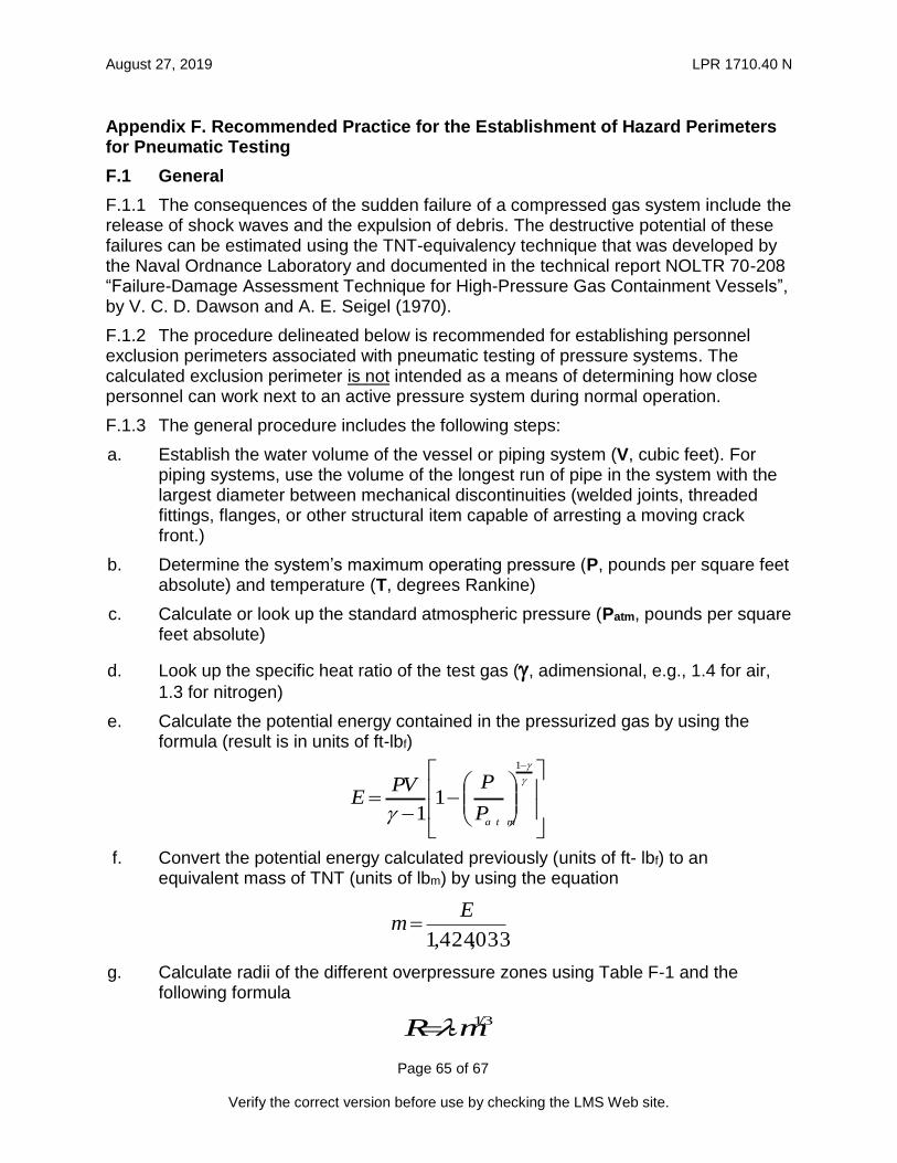
August 27, 2019 LPR 1710.40 N
Page 65 of 67
Verify the correct version before use by checking the LMS Web site.
Appendix F. Recommended Practice for the Establishment of Hazard Perimeters for Pneumatic Testing
F.1 General
F.1.1 The consequences of the sudden failure of a compressed gas system include the release of shock waves and the expulsion of debris. The destructive potential of these failures can be estimated using the TNT-equivalency technique that was developed by the Naval Ordnance Laboratory and documented in the technical report NOLTR 70-208 “Failure-Damage Assessment Technique for High-Pressure Gas Containment Vessels”, by V. C. D. Dawson and A. E. Seigel (1970).
F.1.2 The procedure delineated below is recommended for establishing personnel exclusion perimeters associated with pneumatic testing of pressure systems. The calculated exclusion perimeter is not intended as a means of determining how close personnel can work next to an active pressure system during normal operation.
F.1.3 The general procedure includes the following steps:
a. Establish the water volume of the vessel or piping system (V, cubic feet). For piping systems, use the volume of the longest run of pipe in the system with the largest diameter between mechanical discontinuities (welded joints, threaded fittings, flanges, or other structural item capable of arresting a moving crack front.)
b. Determine the system’s maximum operating pressure (P, pounds per square feet absolute) and temperature (T, degrees Rankine)
c. Calculate or look up the standard atmospheric pressure (Patm, pounds per square feet absolute)
d. Look up the specific heat ratio of the test gas (, adimensional, e.g., 1.4 for air,
1.3 for nitrogen)
e. Calculate the potential energy contained in the pressurized gas by using the formula (result is in units of ft-lbf)
f. Convert the potential energy calculated previously (units of ft- lbf) to an equivalent mass of TNT (units of lbm) by using the equation
g. Calculate radii of the different overpressure zones using Table F-1 and the following formula
033,424,1
Em
3/1mR
1
11
a t mP
PPVE

August 27, 2019 LPR 1710.40 N
Page 66 of 67
Verify the correct version before use by checking the LMS Web site.
Table F-1 Effects of Blast Overpressure
Zone P, psid , ft/(lb1/3) Comment
1 < 0.2 147.8 Safe distance for all personnel. During system pressure testing, a personnel exclusion perimeter should be normally set at this distance.
2 0.5 – 1.0 76.7 – 45.8 Slight damage may occur; glass may shatter. The exclusion perimeter may be set in this range with approval from the SPE for Pressure Systems.
3 1.0 – 5.0 45.8 – 14.7
Moderate damage to wood frame structures may occur. Corrugated asbestos siding may shatter. Corrugated steel or aluminum paneling may buckle.
4 5.0 14.7 Eardrums may rupture.
5 7.0 – 8.0 12.1 – 11.2 Non-reinforced brick walls 8" to 12" thick may shear and fail.
6 10.0 10 Lung damage may occur.
When conducting pneumatic tests above the design pressure or MAWP of a pressure system, all personnel shall be excluded from the perimeter calculated per this procedure, with the exception of the minimum number of personnel required to properly conduct the test. All personnel shall wear appropriate Personal Protective Equipment (PPE) while inside the exclusion perimeter. All personnel shall move outside of the exclusion perimeter during pressure holding times.
Example calculation:
A compressed air piping system consists of mainly 3” schedule 160 piping, operating at 4500 psig. The longest run of piping between two discontinuities is 20 feet.
→ 2.624” is nominal inside diameter of pipe
(cubic feet)
(pounds per square foot, absolute)
)20(12
624.2
4
2
V
3751.0 f tV
psfaP 160,650)144()154500(

August 27, 2019 LPR 1710.40 N
Page 67 of 67
Verify the correct version before use by checking the LMS Web site.
(pounds of mass)
Then, the distance from the center to the 0.2 psid perimeter (Zone 1) is
Similarly, the range of distances defining each zone can be calculated.
psfaPat m
216014415
RankineT 520
4.1
4.1
)4.11(
2160
6501601
)14.1(
)751.0)(650160(E ftlbE
f 000,982
mlbm 69.0
1424033
982000
feetmR 131)69.0(8.147 3/13/1
![LPR 7320.1[1]](https://static.fdocuments.us/doc/165x107/577d36361a28ab3a6b927df7/lpr-732011.jpg)