Landing Force Controller for Humanoid Robot: Time …robot.kut.ac.kr/papers/lfchr.pdf · Landing...
6
2006 IEEE International Conference on Systems, Man, and Cybernetics October 8-11, 2006, Taipei, Taiwan Landing Force Controller for a Humanoid Robot: Time-Domain Passivity Approach Yong-Duk Kim, Bum-Joo Lee, Jeong-Ki Yoo, Jong-Hwan Kim, and Jee-Hwan Ryu Abstract- For the purpose of a humanoid robot's stable walking or running, it is important to absorb landing force or ground reaction force which is generated when the robot's foot lands on the ground surface. The force can make the robot unstable, and the problem becomes serious if the robot runs. This paper proposes a control system, which can absorb the landing force of a humanoid robot. Time-domain passivity control approach is applied for this purpose. Ground and the robot's foot are modeled as two one-port network systems, which are connected and exchange energy with each other. The time-domain passivity controller has the landing force as input and controls the foot's position to reduce the force. The proposed controller can guarantee the stability of the robot system without need of any dynamic model information or control parameters. Using small sized humanoid robot, dynamic walking experiments are performed to verify the proposed scheme, and its efficiency is shown from the comparison with the other scheme. I. INTRODUCTION Many research groups in the world are currently work- ing on humanoid robots and there are many successful projects [1], [2], [3], [4]. Current research, being conducted in collaborating operations with human beings [5],[6], has progressed far beyond studies in walking trajectory gener- ation [7],[8] and online (real-time) balance control [9],[10] during walking. But the basic and most important function of the humanoid robot is the ability to walk safely in the real environment. For a stable walking, it is important to absorb either landing force or ground reaction force, which is produced when the robot's foot lands on the ground surface. The force can make the robot unstable during walking, and if the robot runs, it becomes a serious impediment for maintaining stability. In a typical human locomotion, leg muscles are repeatedly hardened and relaxed depending on the walking pattern phase [11]. Once the muscles that move the leg hit the ground, they tend to be softer for a while to reduce the forces. In order to maintain support, they get harder again and this process is repeated in over and over again. For a walking or running robot, several approaches have been studied to reduce contact force. Some heuristic approaches have been used to shift the foot position once it reaches the surface [12], [13], [14]. However, there are problems in changing the foot position and PID controller coefficients voluntarily. Yong-Duk Kim, bum-Joo Lee, Jeong-Ki Yoo, and Jong-Hwan Kim are with the Robot Intelligence Technology Laboratory, Dept. of EECS, KAIST, Guseong-dong, Yuseong-gu, Daejeon, 305-701, Republic of Korea {ydkim,bjlee,jkyoo,johkim}@rit.kaist.ac.kr Jee-Hwan Ryu is with the School of Mechanical Engineering, Korea University of Technology and Education, Cheoan-city, 330-708, Republic of Korea j hryu@kut . ac . kr Several researchers have studied the hybrid impedance and computed torque control, and the hybrid position and force control for the impedance adjustment of the leg LI5],[16]. In this situation, however, the complex dynamics of the robot must be known, apart from it being difficult to find control parameters. In addition to these, there is a study which tries to decrease the landing force using a special foot structure [17]. This paper proposes a novel controller to compensate the landing force of a humanoid robot. Time-domain passivity approach [18],[19] is implemented for this purpose. The robot's foot is modeled as a one-port network system, which has the landing force as an input, and foot's position as an output. By calculating the energy input into the one-port network based on the landing force and the foot position, the robot's foot is controlled to absorb the landing force. The proposed control method can guarantee the stable dy- namic walking without any model information and control parameters, which must be determined by calculation or trials and errors. Moreover it requires very little additional computation. The validity of the proposed control method is confirmed through dynamic walking experiments using the small-sized humanoid robot, HanSaRam-VI. The efficiency is also shown from the comparison between the proposed scheme and the other one. The remainder of this paper is organized as follows. In Section II, the small-sized humanoid robot, HanSaRam-VI, is described. Section III presents the modeling of robot's foot system which consists of robot's foot and ground surface, and the time-domain passivity control is proposed to compensate the landing force. Section V presents the experimental re- sults of the proposed method. Finally, conclusion follows in Section VI. II. HUMANOID ROBOT HANSARAM-VI TABLE I SPECIFICATIONS t)F HANSARAM-VI Link Length ]j Joint DOF ~~~~~~~. *- - \ - I - Length between hip joints Length of thigh Length of shank Length between ankle and sole Length between toe and heel Width of foot Length of lower trunk Length of upper trunk Length between shoulder joints Length of upper arm Length of lower arm 60 [mm] 100 [mm] 100 [mm] 40 [mm] 100 [mm] 60 [mm] 100 [mm] 100 [mm] 160 [mm] 97 [mm] 86 [mm] Hip Knee Ankle Waist Shoulder Elbow Wrist Total 3 (x2) 1 (x2) 2 (x2) 1 3 (x2) 1 (x2) 2 (x2) 25 1-4244-0100-3/06/$20.00 C2006 IEEE - - I ------I 4237
Transcript of Landing Force Controller for Humanoid Robot: Time …robot.kut.ac.kr/papers/lfchr.pdf · Landing...
2006 IEEE International Conference on
Systems, Man, and CyberneticsOctober 8-11, 2006, Taipei, Taiwan
Landing Force Controller for a Humanoid Robot: Time-DomainPassivity Approach
Yong-Duk Kim, Bum-Joo Lee, Jeong-Ki Yoo, Jong-Hwan Kim, and Jee-Hwan Ryu
Abstract- For the purpose of a humanoid robot's stablewalking or running, it is important to absorb landing forceor ground reaction force which is generated when the robot'sfoot lands on the ground surface. The force can make therobot unstable, and the problem becomes serious if the robotruns. This paper proposes a control system, which can absorbthe landing force of a humanoid robot. Time-domain passivitycontrol approach is applied for this purpose. Ground and therobot's foot are modeled as two one-port network systems,which are connected and exchange energy with each other.The time-domain passivity controller has the landing force asinput and controls the foot's position to reduce the force. Theproposed controller can guarantee the stability of the robotsystem without need of any dynamic model information orcontrol parameters. Using small sized humanoid robot, dynamicwalking experiments are performed to verify the proposedscheme, and its efficiency is shown from the comparison withthe other scheme.
I. INTRODUCTION
Many research groups in the world are currently work-ing on humanoid robots and there are many successfulprojects [1], [2], [3], [4]. Current research, being conductedin collaborating operations with human beings [5],[6], hasprogressed far beyond studies in walking trajectory gener-ation [7],[8] and online (real-time) balance control [9],[10]during walking. But the basic and most important functionof the humanoid robot is the ability to walk safely in thereal environment. For a stable walking, it is important toabsorb either landing force or ground reaction force, which isproduced when the robot's foot lands on the ground surface.The force can make the robot unstable during walking,and if the robot runs, it becomes a serious impediment formaintaining stability.
In a typical human locomotion, leg muscles are repeatedlyhardened and relaxed depending on the walking pattern phase[11]. Once the muscles that move the leg hit the ground,they tend to be softer for a while to reduce the forces. Inorder to maintain support, they get harder again and thisprocess is repeated in over and over again. For a walkingor running robot, several approaches have been studied toreduce contact force. Some heuristic approaches have beenused to shift the foot position once it reaches the surface[12], [13], [14]. However, there are problems in changingthe foot position and PID controller coefficients voluntarily.
Yong-Duk Kim, bum-Joo Lee, Jeong-Ki Yoo, and Jong-Hwan Kimare with the Robot Intelligence Technology Laboratory, Dept. of EECS,KAIST, Guseong-dong, Yuseong-gu, Daejeon, 305-701, Republic of Korea{ydkim,bjlee,jkyoo,johkim}@rit.kaist.ac.krJee-Hwan Ryu is with the School of Mechanical Engineering, Korea
University of Technology and Education, Cheoan-city, 330-708, Republicof Korea j hryu@kut . ac . kr
Several researchers have studied the hybrid impedance andcomputed torque control, and the hybrid position and forcecontrol for the impedance adjustment of the leg LI5],[16]. Inthis situation, however, the complex dynamics of the robotmust be known, apart from it being difficult to find controlparameters. In addition to these, there is a study which triesto decrease the landing force using a special foot structure[17].
This paper proposes a novel controller to compensate thelanding force of a humanoid robot. Time-domain passivityapproach [18],[19] is implemented for this purpose. Therobot's foot is modeled as a one-port network system, whichhas the landing force as an input, and foot's position as anoutput. By calculating the energy input into the one-portnetwork based on the landing force and the foot position,the robot's foot is controlled to absorb the landing force.The proposed control method can guarantee the stable dy-namic walking without any model information and controlparameters, which must be determined by calculation ortrials and errors. Moreover it requires very little additionalcomputation. The validity of the proposed control method isconfirmed through dynamic walking experiments using thesmall-sized humanoid robot, HanSaRam-VI. The efficiencyis also shown from the comparison between the proposedscheme and the other one.The remainder of this paper is organized as follows. In
Section II, the small-sized humanoid robot, HanSaRam-VI,is described. Section III presents the modeling of robot's footsystem which consists of robot's foot and ground surface, andthe time-domain passivity control is proposed to compensatethe landing force. Section V presents the experimental re-sults of the proposed method. Finally, conclusion follows inSection VI.
II. HUMANOID ROBOT HANSARAM-VI
TABLE I
SPECIFICATIONS t)F HANSARAM-VILink Length ]j Joint DOF~~~~~~~. *- - \ - I -Length between hip joints
Length of thighLength of shank
Length between ankle and soleLength between toe and heel
Width of footLength of lower trunkLength of upper trunk
Length between shoulder jointsLength of upper armLength of lower arm
60 [mm]100 [mm]100 [mm]40 [mm]100 [mm]60 [mm]100 [mm]100 [mm]160 [mm]97 [mm]86 [mm]
HipKneeAnkleWaist
ShoulderElbowWristTotal
3 (x2)1 (x2)2 (x2)
13 (x2)1 (x2)2 (x2)
25
1-4244-0100-3/06/$20.00 C2006 IEEE
- - I ------I
4237

Fig. 1. HanSaRam-VI.
Fig. 1 and Table I show a small-sized humanoid robot,HanSaRam-VI and its specification. It has 25 DOFs, andconsists of 12 DC motors in lower body and 13 RC servomotors in upper body. Its height and weight are 52 cm and4.5 kg, respectively. This biped robot's structure is mainlycomposed of Duralumin. Even though HanSaRam-VI is asmall humanoid robot, the design of the lower body isfocused on generating sufficient power and accurate control,and therefore consists of DC motors and Harmonic drives.In the design of the upper body, 13 RC servo motors areused, due to light weight and easy to control.The on-board Pentium-IlI compatible PC with running RT-
Linux calculates the walking pattern in real time. The walk-ing pattern is generated on-line based on three-dimensionalinverted pendulum model [20]. The stand-alone vision sys-tem using PDA is equipped to find out three colored objectsin real time. To measure forces on the foot, 4 FSRs areequipped on each foot.
With the help of all the computational and power parts,HanSaRam-VI has the ability for fully independent sensing,processing, and locomotion.
III. LANDING FORCE CONTROLLER USING TIME-DOMAINPASSIVITY APPROACH
A. The time-domain passivityIn this section, we briefly review time-domain passivity
concept before it is implemented for absorbing the landingforce. Recently, the sampled time passivity concept has beenproposed in [21], because many of the input and outputvariables in control problems can be measured by computer,and the conjugate variables which define power flow insuch a computer system are sampled time values. The robotcontrol system to compensate the landing force is assumedto take a force as an input, and computes foot's positionas its output. Typically, this input force is measured byforce sensors and used through AD converter at each sampletime. And the computed position output is applied to amotor controller so that motors can follow reference positioncontinuously.
Fig. 2. One-port network model.
First, we define the sign convention for all forces andvelocities so that their product is positive when power entersthe system port. Also, the system is assumed to have initialstored energy at t = 0 of E(0) (Fig. 2). Following variablesfor force and position are defined during one sample timetk 1 < t < tk for the sampled time system:
1) f(t) = F(k) is the force at k, which is constant duringone sample time, tk-1 < t < tk.
2) x(k) and x(k- 1) are the positions at k and k- 1sample times, respectively.
Then, the passivity of the sampled system can be definedas the following:
Definition 1: The one-port network N with initial energystorage E(O) is sampled time passive if and only if
k
E(k) = ,: F(j')(x(j)-x(j-1)) + E(O) > O (1)j=o
where j 0,1, 2, .. ., k 0,1, 2, .. ., for sampled forceF(j) and position x(j).
Note that if E(k) > 0 for every k, this means the systemdissipates energy. If there is an instance that E(k) < 0,this means the system generates energy, and the amount ofgenerated energy is -E(k).
B. Modeling robot's foot system
tx
Foot
f
Ground
(a) Robot's foot and ground sur- (b) One-port networkface. models of the robot's
foot and ground sur-face
Fig. 3. Robot's foot system modeling.
To implement the time-domain passivity approach, therobot's foot and the ground are modeled as a network system.Both systems can be modeled as one-port network systems,which are connected each other. Fig. 3 shows the real and the
4238
A1

modeled network system, respectively. The sign conventionfor force and velocity is defined so that the energy is positivewhen the power enters the system port of the robot's foot. InFig. 3(b), the force and the velocity are positive in the upperdirection.
Since the ground can be considered as an intrinsicallypassive system, the connected system (the robot's foot andthe ground) can be passive if the robot's foot, the one portnetwork, is passive. This is a situation where the foot isphysically absorbing the contact force. Once we prove thepassivity, stability of the robot system can be also guranteedbecause passivity is a sufficient condition of stability.On the other hand, when the robot's foot, one port net-
work, is active (while the input energy is negative), the robotmight be unstable. This is the case when the robot's footkicks the surface, which causes a big landing force betweenthe foot and the ground. This force is the main reason for theunstable walking. Therefore, a control algorithm is requiredfor alleviating the landing force.
C. Landing force controller
Robotr----------------------,1Ax I f, I
3~~Fig. 4. One-port network with P0/PC.
We can divide the one-port network of the robot's footsystem into two parts: mechanism part with low-level po-sition controller and planner part with high-level controller.Fig. 4 shows the separated network system of robot's foot.f ( fi f2) iS the landing force, which can be measuredby the FSR sensors on the robot's foot. x is the actual heightposition of the robot's foot, and A\x is the difference betweentwo consecutive sampled data of x. The modified position(x1) is obtained from the originally planned walking pattern(x2) and the output of the passivity controller (Sxpc). x2 is aplanned height position of walking pattern from the walkingpattern planner, which did not consider the landing forcefrom the ground. If we use the planned walking pattern, therobot's foot might get a big landing force from the groundin a very short time, and it makes the one-port of the robot'sfoot active. In order to reduce the landing force, the passivitycontroller is attached to modify the planned walking pattern(x2) to x1 by adding 6xp. Therefore, the robot takes theground reaction force into account and it can make a contactto the ground more securely.
The proposed time-domain passivity control system con-sists of a passivity controller (PC) and passivity observer(PO), which controls and monitors the input/output energyflow between the robot's foot and the ground. Passivityobserver computes the energy flow using the landing forceand the foot position as follows:
W(k) = W(k -1) + f, (k)(xi (k) - xi (k - 1)) (2)
Wo(k + 1) = W(k) + fi (k)(x2(k + 1) - xi (k)) (3)
where W(k) is the total energy output from 0 to k, andWo(k + 1) is the prediction of the one-step-ahead energyoutput. The last term of Eq. (3) is the estimation of the one-step-ahead energy output, which is the output energy from kto k + 1. Note that we know the planned position x2(k + 1)at step k. If the PO can predict whether the system at thenext step will be passive or not at the current step k, thePC can modify the desired position at the next step (k + 1)to make the system passive. The PC absorbs exactly the netenergy output (if any) measured by the passivity observer ateach time sample.
Based on the PO (steps 4 and 5 below), the PC algorithm(steps 6 and 7 below) for the one-port robot's foot isdeveloped as follows:
1) f1 (k) = f2(k) is the input;2) Ax, (k) = xi (k) - x1(k - 1)
AX2(k + 1)= x2(k + 1) - xi(k);3) AX2(k) is the output of the one-port network;4) W(k) = W(k- 1) + f1 (k)Ax, (k) is the energy output
at step k5) Wo(k+1) = W(k)+fi(k)Ax2(k+i1) is the prediction
of the energy level at step k + 16) The PC output for making the system passive is
calculated as follows:
f-W,,(k+1) if W0(k + 1) < 0
r 10 if Wo(k + 1) > 0
7) The modified desired height position can be calculatedfrom Ax, (k + 1) = AX2 (k + 1) + 3xpc (k).
It should be noted that the PO/PC is for achieving thestable landing of humanoid robot. Once the stable landing isachieved (maintaining N steps with positive energy, whereN is constant.), the robot's walking path should be modifiedto follow the initially planned walking path. The walkingpattern, changed by the passivity controller, is interpolated tothe initially planned walking pattern by using the polynomialmethod. In this stage, passivity observer is also reset toprepare the next observation.
IV. EXPERIMENTS
Dynamic walking experiments were performed to verifythe proposed time-domain passivity control approach. Theresults are compared with those using no landing forcecontrol and the heuristic control to absorb the force. In theexperiments, the biped robot walked with a speed of 4 cm/s
4239
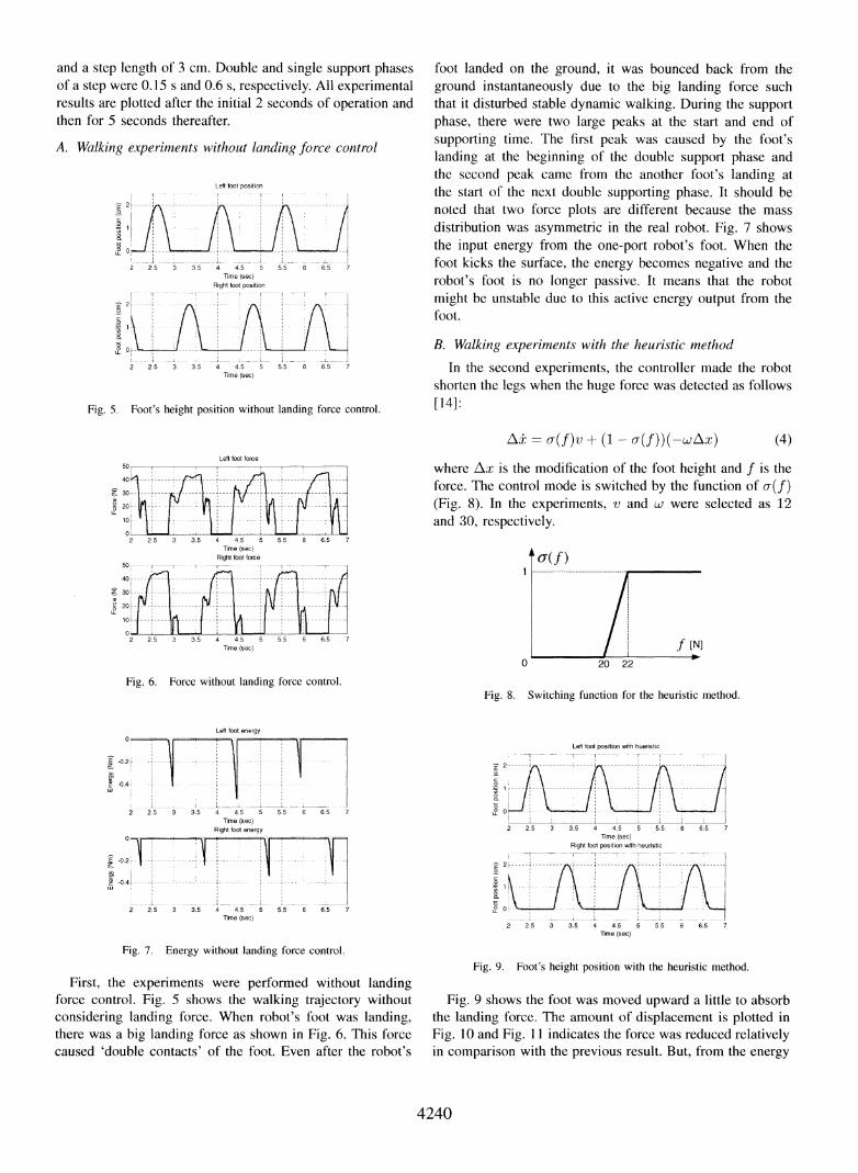
and a step length of 3 cm. Double and single support phasesof a step were 0.15 s and 0.6 s, respectively. All experimentalresults are plotted after the initial 2 seconds of operation andthen for 5 seconds thereafter.
A. Walking experiments without landing force control
Left foot position
I1!r -- -~ I II
2.5 3 3.5 4 4.5 5 5.5 6 6.5 7Time (sec)
Fig. 5. Foot's height position without landing force control.
foot landed on the ground, it was bounced back from theground instantaneously due to the big landing force suchthat it disturbed stable dynamic walking. During the supportphase, there were two large peaks at the start and end ofsupporting time. The first peak was caused by the foot'slanding at the beginning of the double support phase andthe second peak came from the another foot's landing atthe start of the next double supporting phase. It should benoted that two force plots are different because the massdistribution was asymmetric in the real robot. Fig. 7 showsthe input energy from the one-port robot's foot. When thefoot kicks the surface, the energy becomes negative and therobot's foot is no longer passive. It means that the robotmight be unstable due to this active energy output from thefoot.
B. Walking experiments with the heuristic methodIn the second experiments, the controller made the robot
shorten the legs when the huge force was detected as follows[14]:
\ a(f)v + (1 - o(f))(-wAX)Left foot force
Z 30a)
Y 20LL
10
0L
40L
2
40r
2' 30!
2 20LL
10I0
(4)
where Ax is the modification of the foot height and f is theforce. The control mode is switched by the function of u(f)(Fig. 8). In the experiments, v and w were selected as 12and 30, respectively.
Fig. 6. Force without landing force control.
LeR foot energy
-0.2 -
-0.4
2 2.5 3 3.5 4 4.5 5Time (sec)
Right foot energy
2 2.5 3 3.5 4 4.5 5Time (sec)
55 6 6.5 7
5.5 6 65
Fig. 8. Switching function for the heuristic method.
Left foot position with hueristic
-;--
tL 0
2 2.5 3 305 4 4.5 5 5.5 6 6.5 7Time (sec)
Right foot position wih heuostic--T r--r- v
2 2.5 3 3.5 4 4.5 5 5.5 6 6.5 7lime (sec)
7
Fig. 7. Energy without landing force control.
First, the experiments were performed without landingforce control. Fig. 5 shows the walking trajectory withoutconsidering landing force. When robot's foot was landing,there was a big landing force as shown in Fig. 6. This forcecaused 'double contacts' of the foot. Even after the robot's
Fig. 9. Foot's height position with the heuristic method.
Fig. 9 shows the foot was moved upward a little to absorbthe landing force. The amount of displacement is plotted inFig. 10 and Fig. 11 indicates the force was reduced relativelyin comparison with the previous result. But, from the energy
4240
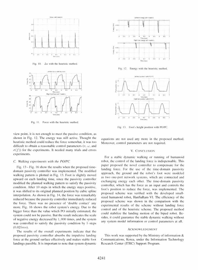
Delta z with heuristic
Fig. 10. Ax with the heuristic method.
Left foot force with heuristic
40
Z 30'2 20.LL
10
Time (sec)
Fig. 11. Force with the heuristic method.
Fig. 12. Energy with the heuristic method.
Left foot position with PO/PC
2 2.5 3 3.5 4 4.5 5 5.5 6 6.5 7Time (sec)
Right foot position with PO/PC
2 2.5 3 3.5 4 4.5 5 5.5 6 6.5 7Time (sec)
Fig. 13. Foot's height position with PO/PC.
view point, it is not enough to meet the passive condition, as
shown in Fig. 12. The energy was still active. Thought theheuristic method could reduce the force somewhat, it was too
difficult to obtain a reasonable control parameters (v, w, andcX(f)) for the experiments. It needed many trials and errors
experiments.
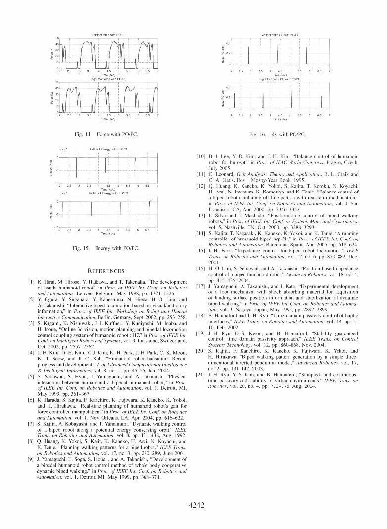
C. Walking experiments with the PO/PC
Fig. 13 - Fig. 16 show the results when the proposed time-domain passivity controller was implemented. The modifiedwalking pattern is plotted in Fig. 13. Foot is slightly movedupward on each landing time, since the passivity controllermodified the planned walking pattern to satisfy the passivitycondition. After 10 steps in which the energy stays positive,it was shifted to its original planned position by cubic splineinterpolation. As shown in Fig. 14, the force was remarkablyreduced because the passivity controller immediately reducedthe force. There was no presence of 'double contact' any
more. Fig. 16 shows the robot system's energy. Due to thebigger force than the value which PO initially estimated, thesystem could not be passive. But the result indicates the scaleof negative energy decreased by 1, 000 times, and the systemwas controlled to satisfy the passivity condition by 5 steps(0.025rns).The results of the overall experiments indicate that the
proposed passivity controller absorbs the impulsive landingforce at the ground surface effectively and makes stable foot
landings passible. It is important to note that system dynamic
equations are not used any more in the proposed method.Moreover, control parameters are not required.
V. CONCLUSION
For a stable dynamic walking or running of humanoidrobot, the control of the landing force is indispensable. Thispaper proposed the novel controller to compensate for thelanding force. For the use of the time-domain passivityapproach, the ground and the robot's foot were modeledas two one-port network systems, which are connected andexchanging energy each other. The time-domain passivitycontroller, which has the force as an input and controls thefoot's position to reduce the force, was implemented. Theproposed scheme was verified with the developed small-sized humanoid robot, HanSaRam-VI. The efficiency of theproposed scheme was shown in the comparison with theexperimental results of the scheme without landing forcecontrol and of the heuristic scheme. The proposed methodcould stabilize the landing motion of the biped robot. Be-sides, it could guarantee the stable dynamic walking withoutany system model information or control parameters at all.
ACKNOWLEDGMENT
This work was supported by the Ministry of information &Communications, Korea, under the Information TechnologyResearch Center (ITRC) Support Program.
4241
E _
21
2'
Left toot force with PO/PCr-- --i
0.4
° 0.2
a) ___
-E
-sa
I02 2.5 3 35 4 45 5 5.5 6 6.5 7
Time (sec)Right foot delta PC with PO/PC
0.4
2 2.5 3 3.5 4 4.5 5 5.5 6 6.5 7Time (sec)
Fig. 14. Force with PO/PC. Fig. 16. bx with PO/PC.
x lo-, Left foot Energy with PO/PCr-T--- - --- -- r __IAV _
ifI
uJ
-10 1- ,- 1, i---- L _,_,2 2.5 3 3.5 4 4.5 5 5.5 6
Time (sec)x 10t3 Right foot Energy with PO/PC
65 7
E
m 5LD
2 2.5 3 3.5 4 4.5 5 5.5 6 6.5 7lime (sec)
Fig. 15. Energy with PO/PC.
REFERENCES
[1] K. Hirai, M. Hirose, Y. Haikawa, and T. Takenaka, "The developmentof honda humanoid robot," in Proc. of IEEE Int. Conf. on Roboticsand Automations, Leuven, Belgium, May 1998, pp. 1321-1326.
[2] Y. Ogura, Y. Sugahara, Y. Kaneshima, N. Hieda, H.-O. Lim, andA. Takanishi, "Interactive biped locomotion based on visual/audiotoryinformation," in Proc. of IEEE Int. Workshop on Robot and HumanInteractive Communication, Berlin, Gemany, Sept. 2002, pp. 253-258.
[3] S. Kagami, K. Nishiwaki, J. J. Kuffner., Y. Kuniyoshi, M. Inaba, andH. Inoue, "Online 3d vision, motion planning and bipedal locomotioncontrol coupling system of humanoid robot H7," in Proc. ofIEEE Int.Con on Intelligent Robots and Systems, vol. 3, Lausanne, Switzerland,Oct. 2002, pp. 2557-2562.
[4] J.-H. Kim, D.-H. Kim, Y.-J. Kim, K.-H. Park, J.-H. Park, C.-K. Moon,K. T. Seow, and K.-C. Koh, "Humanoid robot hansaram: Recentprogress and development," J. ofAdvanced Computational Intelligence& Intelligent Informatics, vol. 8, no. 1, pp. 45-55, Jan. 2004.
[5] S. Setiawan, S. Hyon, J. Yamaguchi, and A. Takanish, "Physicalinteraction between human and a bipedal humanoid robot," in Proc.of IEEE Int. Conf on Robotics and Automation, vol. 1, Detroit, MI,May 1999, pp. 361-367.
[6] K. Harada, S. Kajita, F Kanehiro, K. Fujiwara, K. Kaneko, K. Yokoi,and H. Hirukawa, "Real-time planning of humanoid robot's gait forforce controlled manipulation," in Proc. ofIEEE Int. Conf on Roboticsand Automation, vol. 1, New Orleans, LA, Apr. 2004, pp. 616-622.
[7] S. Kajita, A. Kobayashi, and T. Yamamura, "Dynamic walking controlof a biped robot along a potential energy conserving orbit," IEEETrans. on Robotics and Automation, vol. 8, pp. 431-438, Aug. 1992.
[8] Q. Huang, K. Yokoi, S. Kajit, K. Kaneko, H. Arai, N. Koyachi, andK. Tanie, "Planning walking patterns for a biped robot," IEEE Trans.on Robotics and Automation, vol. 17, no. 3, pp. 280-289, June 2001.
[9] J. Yamaguchi, E. Soga, S. Inoue,, and A. Takanishi, "Development ofa bipedal humanoid robot control method of whole body cooperativedynamic biped walking," in Proc. of IEEE Int. Conf on Robotics andAutomation, vol. 1, Detroit, MI, May 1999, pp. 368-374.
[10] B.-J. Lee, Y.-D. Kim, and J.-H. Kim, "Balance control of humanoidrobot for hurosot," in Proc. of IFAC World Congress, Prague, Czech,July 2005.
[11] C. Leonard, Gait Analysis: Theory and Application, R. L. Craik andC. A. Oatis, Eds. Mosby-Year Book, 1995.
[12] Q. Huang, K. Kaneko, K. Yokoi, S. Kajita, T. Kotoku, N. Koyachi,H. Arai, N. Imamura, K. Komoriya, and K. Tanie, "Balance control ofa biped robot combining off-line pattern with real-teim modification,"in Proc. of IEEE Int. Conf on Robotics and Automation, vol. 4, SanFrancisco, CA, Apr. 2000, pp. 3346-3352.
[13] F Silva and J. Machado, "Position/force control of biped walkingrobots," in Proc. of IEEE Int. Conf. on System, Man, and Cybernetics,vol. 5, Nashville, TN, Oct. 2000, pp. 3288-3293.
[14] S. Kajita, T. Nagasaki, K. Kaneko, K. Yokoi, and K. Tanie, "A runningcontroller of humanoid biped hrp-21r," in Proc. of IEEE Int. Conf: onRobotics and Automation, Barcelona, Spain, Apr. 2005, pp. 618-624.
[15] J.-H. Park, "Impedance control for biped robot locomotion," IEEETrans. on Robotics and Automation, vol. 17, no. 6, pp. 870-882, Dec.2001.
[16] H.-O. Lim, S. Setiawan, and A. Takanishi, "Position-based impedancecontrol of a biped humanoid robot," Advanced Robotics, vol. 18, no. 4,pp. 415-435, 2004.
[17] J. Yamaguchi, A. Takanishi, and I. Kato, "Experimental developmentof a foot mechanism with shock absorbing material for acquisitionof landing surface position information and stabilization of dynamicbiped walking," in Proc. ofIEEE Int. Conf. on Robotics and Automa-tion, vol. 3, Nagoya, Japan, May 1995, pp. 2892-2899.
[18] B. Hannaford and J.-H. Ryu, "Time-domain passivity control of hapticinterfaces," IEEE Trans. on Robotics and Automation, vol. 18, pp. 1-10, Feb. 2002.
[19] J.-H. Ryu, D.-S. Kwon, and B. Hannaford, "Stability guaranteedcontrol: time domain passivity approach," IEEE Trans. on ControlSystems Technology, vol. 12, pp. 860-868, Nov. 2004.
[20] S. Kajita, F. Kanehiro, K. Kaneko, K. Fujiwara, K. Yokoi, andH. Hirukawa, "Biped walking pattern generation by a simple three-dimentional inverted pendulum model," Advanced Robotics, vol. 17,no. 2, pp. 131-147, 2003.
[21] J.-H. Ryu, Y.-S. Kim, and B. Hannaford, "Sampled- and continuous-time passivity and stability of virtual environments," IEEE Trans. onRobotics, vol. 20, no. 4, pp. 772-776, Aug. 2004.
4242
Z30.
205
40
Z3-2
501-
40
z 30'
0' 20LL
Time (sec)Right foot force with PO/PC
_ -
Lefttfoot deHta PC with PO/PC