
Land Subsidence and Earth Fissuring on the Central Arizona...
12
Land Subsidence (Proceedings of the Fourth International Symposium on Land Subsidence, May 1991). IAHS Publ. no. 200,1991. Land Subsidence and Earth Fissuring on the Central Arizona Project, Arizona J. P. SANDOVAL & S. R. BARTLETT US Bureau of Reclamation, Arizona Projects Office, Phoenix, Arizona, USA ABSTRACT Land subsidence and earth fissures have significantly impacted the design, construction and operation of the CAP. Reclamation and the USGS began geologic investigations in 1977 to determine subsidence design parameters and to identify fissure hazard zones. The investigations consisted of field mapping, test drilling, borehole instrumentation, and geophysical surveys. The subsequent designs accommodated 0.1 to 4.6 meters of subsidence over the 50-year operating period and included resteel within the canal lining to bridge fissures. To monitor the rate of subsidence, several methods have been employed including GIS and GPS. Fissure mitigation is extremely difficult because fissures propagate upward from the water table to the ground surface. Following construction, remedial treatment including buried barrier walls, filling, and capping have been required adjacent to CAP structures. To coordinate current and future mitigation techniques, a fissure committee was formed. Key elements of a successful fissure mitigation program include education, early detection, and prompt remedial treatment. GENERAL The Central Arizona Project (CAP) is being constructed by the Bureau of Reclamation (Reclamation) to deliver Colorado River water to central and southern Arizona. This water will replace existing groundwater uses and supplement surface water supplies. The CAP will deliver an average of 1.8 X 10 9 m 3 /s of water yearly to cities and industries, Indian communities, and farmers. The 536 km long CAP system of concrete-lined canals, inverted siphons, tunnels, pumping plants, pipelines, turnouts, and check structures will convey Colorado River water across Arizona. The system consists of three aqueducts (Hayden- Rhodes, Salt-Gila, and Tucson) which are similar in design but vary in the size of canal prisms and the number of pumping plants (Fig. 1). The system capacity varies from 85 m 3 /s at the Colorado River (Havasu Pumping Plant) to 5.7 m 3 /s at the end of the Tucson Aqueduct. The total lift of 880 meters from the Colorado River to Tucson is accomplished by 14 pumping plants. In addition to its major components, the CAP system has many associated features such as dams, roadway bridges, wildlife crossings, drainage overchutes and culverts, protective dikes with related outlet structures, and environmental mitigation features. All of the remote pumping plants, turnouts, and check structures are operated from the project operations and maintenance center in Phoenix by a computerized control and 249
Transcript of Land Subsidence and Earth Fissuring on the Central Arizona...

Land Subsidence (Proceedings of the Fourth International Symposium on Land Subsidence, May 1991). IAHS Publ. no. 200,1991.
Land Subsidence and Earth Fissuring on the Central Arizona Project, Arizona
J. P. SANDOVAL & S. R. BARTLETT US Bureau of Reclamation, Arizona Projects Office, Phoenix, Arizona, USA
ABSTRACT Land subsidence and earth fissures have significantly impacted the design, construction and operation of the CAP. Reclamation and the USGS began geologic investigations in 1977 to determine subsidence design parameters and to identify fissure hazard zones. The investigations consisted of field mapping, test drilling, borehole instrumentation, and geophysical surveys. The subsequent designs accommodated 0.1 to 4.6 meters of subsidence over the 50-year operating period and included resteel within the canal lining to bridge fissures. To monitor the rate of subsidence, several methods have been employed including GIS and GPS. Fissure mitigation is extremely difficult because fissures propagate upward from the water table to the ground surface. Following construction, remedial treatment including buried barrier walls, filling, and capping have been required adjacent to CAP structures. To coordinate current and future mitigation techniques, a fissure committee was formed. Key elements of a successful fissure mitigation program include education, early detection, and prompt remedial treatment.
GENERAL
The Central Arizona Project (CAP) is being constructed by the Bureau of Reclamation (Reclamation) to deliver Colorado River water to central and southern Arizona. This water will replace existing groundwater uses and supplement surface water supplies. The CAP will deliver an average of 1.8 X 10⁹ m3/s of water yearly to cities and industries, Indian communities, and farmers. The 536 km long CAP system of concrete-lined canals, inverted siphons, tunnels, pumping plants, pipelines, turnouts, and check structures will convey Colorado River water across Arizona. The system consists of three aqueducts (Hayden-Rhodes, Salt-Gila, and Tucson) which are similar in design but vary in the size of canal prisms and the number of pumping plants (Fig. 1). The system capacity varies from 85 m3/s at the Colorado River (Havasu Pumping Plant) to 5.7 m3/s at the end of the Tucson Aqueduct. The total lift of 880 meters from the Colorado River to Tucson is accomplished by 14 pumping plants. In addition to its major components, the CAP system has many associated features such as dams, roadway bridges, wildlife crossings, drainage overchutes and culverts, protective dikes with related outlet structures, and environmental mitigation features. All of the remote pumping plants, turnouts, and check structures are operated from the project operations and maintenance center in Phoenix by a computerized control and
249

/. P. Sandoval & S. R. Bartlett 250
) Page
O»o«! aà°
H A V A S U »
Parker
ns R " o r
> DOUSE H I L L S
G&ANBTE KEEF AQUEDUCT
HASSAYAMPA
LITTLE HAROUAHALA
&K *\*t
Yuma
MARICOPA COUNTY
o FLAGSTAFF
\Q
New Woddell Dam Site
Projiet H.Q.
PHOENIX
[ StewartV (Mountain ^
Dam
SALT-GILA .AQUEDUCT
G//o
/COOLIDGE1 CASA GRANDEO
SAUTA ROSA CANAL -
PINAL COUNTY RED R O C t f 3 TUCSON
PIMA COUNTY
M A R A N A ^ Â Q U E D U C T
PUMPING PLANT s
T W I N P E A K S -
S A N D A R I O -
B R A W L E Y -
S A N XAVIER -
SNYDER H I L L -
BLACK M O U N T A I N -
FIG. 1 General location map of the Central Arizona Project, Arizona.
communications system through line-of-sight microwave relay stations and buried fiber-optic communications cables. Actual construction began in 1977 and will be completed by 1992.
REGIONAL GEOLOGY
The CAP is located in central and southern Arizona within the Basin and

251 Land subsidence and earth fissuring in Arizona
Range Physiographic Province. The geology of this province is characterized by large-scale block faulting and associated volcanism. The basins formed by the downfaulted blocks have been partially filled with material eroded from the higher surrounding mountain ranges. Also included in the basins are lacustrine deposits and interbedded middle to late Tertiary and Quaternary volcanics. Alluvial deposits commonly occur adjacent to the mountain fronts and cover both the bedrock and the range bounding faults. The cores of the mountain ranges are composed of Precambrian granitic and metamorphic rocks that are often overlain by early to middle Tertiary sedimentary and volcanic rocks. Younger Tertiary volcanic flows and pyroclastics in turn commonly cap the mountains. Alluvial materials deposited in the basins consist of heterogeneous unconsolidated mixtures of clay, silt, sand, and gravel which locally contain cobbles and boulders. This material grades from coarser to finer grained with increasing distances from their sources in the surrounding mountains and is variably cemented by calcium carbonate. Rock hills and knobs protrude through the alluvial materials (USBR 1982 & 1986). During the Pleistocene Epoch when climatic conditions were much wetter than current conditions, the alluvial basins were charged through the percolation of excess surface flows. This initial charging created large groundwater basins with abundant groundwater resource which in turn has influenced greatly recent development in south-central Arizona.
REGIONAL HYDROLOGY
As a consequence of the geological history, the groundwater table lies within the alluvial fan and basin fill deposits resulting in a groundwater surface that slopes gently away from the mountain fronts and occurs at greatest depths in the center of the basins. Streams and washes which drain the area flow only during and immediately after periods of heavy rainfall providing little recharge to the groundwater table. During the past century, groundwater use has increased in central and southern Arizona primarily due to expanded agriculture. Since 1950, groundwater levels have dropped dramatically due to rapidly increased pumping rates. This excessive pumping of the groundwater for agriculture has caused the water table to decline approximately 46 to 152 meters (USBR 1976). Overdraft of groundwater from the basin has resulted in dewatering and compaction of sediments at depth and downwarping of the land surface. The downwarping of the land surface, commonly referred to as land subsidence, has affected the region to varying degrees. Land subsidence is a slow regional process resulting in a downward change in the elevation of the basin relative to the adjacent mountains. Post-construction subsidence along the aqueduct could change the invert gradient of the canal causing local sags in the canal and allowing water to overtop the lining. Therefore, design of the aqueduct required accommodation of anticipated future subsidence estimated to occur by the year 2035.
GEOLOGIC INVESTIGATIONS AND SUBSIDENCE PREDICTIONS
Reclamation and the US Geological Survey (USGS), began investigations of land subsidence and earth fissuring along the Salt-Gila and Tucson Aqueducts in 1977. The purpose of these investigations was to define
/. P. Sandoval & S. R. Bartlett 252
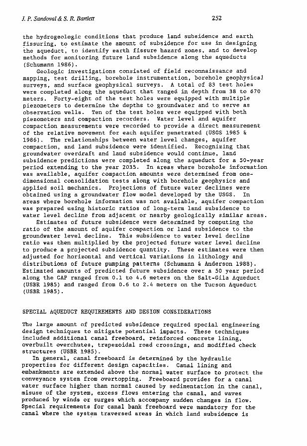
the hydrogeologic conditions that produce land subsidence and earth fissuring, to estimate the amount of subsidence for use in designing the aqueduct, to identify earth fissure hazard zones, and to develop methods for monitoring future land subsidence along the aqueducts (Schumann 1986).
Geologic investigations consisted of field reconnaissance and mapping, test drilling, borehole instrumentation, borehole geophysical surveys, and surface geophysical surveys. A total of 83 test holes were completed along the aqueduct that ranged in depth from 38 to 670 meters. Forty-eight of the test holes were equipped with multiple piezometers to determine the depths to groundwater and to serve as observation wells. Ten of the test holes were equipped with both piezometers and compaction recorders. Water level and aquifer compaction measurements were recorded to provide a direct measurement of the relative movement for each aquifer penetrated (USGS 1985 & 1986). The relationships between water level changes, aquifer compaction, and land subsidence were identified. Recognizing that groundwater overdraft and land subsidence would continue, land subsidence predictions were completed along the aqueduct for a 50-year period extending to the year 2035. In areas where borehole information was available, aquifer compaction amounts were determined from one-dimensional consolidation tests along with borehole geophysics and applied soil mechanics. Projections of future water declines were obtained using a groundwater flow model developed by the USGS. In areas where borehole information was not available, aquifer compaction was prepared using historic ratios of long-term land subsidence to water level decline from adjacent or nearby geologically similar areas.
Estimates of future subsidence were determined by computing the ratio of the amount of aquifer compaction or land subsidence to the groundwater level decline. This subsidence to water level decline ratio was then multiplied by the projected future water level decline to produce a projected subsidence quantity. These estimates were then adjusted for horizontal and vertical variations in lithology and distributions of future pumping patterns (Schumann & Anderson 1988). Estimated amounts of predicted future subsidence over a 50 year period along the CAP ranged from 0.1 to 4.6 meters on the Salt-Gila Aqueduct (USBR 1985) and ranged from 0.6 to 2.4 meters on the Tucson Aqueduct (USBR 1985).
SPECIAL AQUEDUCT REQUIREMENTS AND DESIGN CONSIDERATIONS
The large amount of predicted subsidence required special engineering design techniques to mitigate potential impacts. These techniques included additional canal freeboard, reinforced concrete lining, overbuilt overchutes, trapezoidal road crossings, and modified check structures (USBR 1985).
In general, canal freeboard is determined by the hydraulic properties for different design capacities. Canal lining and embankments are extended above the normal water surface to protect the conveyance system from overtopping. Freeboard provides for a canal water surface higher than normal caused by sedimentation in the canal, misuse of the system, excess flows entering the canal, and waves produced by winds or surges which accompany sudden changes in flow. Special requirements for canal bank freeboard were mandatory for the canal where the system traversed areas in which land subsidence is

253 Land subsidence and earth Assuring in Arizona
occurring. In areas of predicted subsidence, the canal prism freeboard was increased by raising the lining to a height sufficient to contain the water surface after the 50-year predicted subsidence, unless the 50-year predicted subsidence exceeded 10 feet, then the canal prism freeboard was raised to contain the water surface after the,35-year predicted subsidence or 10 feet above the initial water depth, whichever is greater. The interval and magnitude of the lining increments were set to balance the cost of additional materials against the efficient use of the contractor's equipment and forces.
Reinforced concrete lining was used along the canal for two reasons. Reinforced lining was used upstream and downstream of the trapezoidal road crossings to lengthen the potential percolation paths by decreasing the amount of construction joints required and thus increasing the length of the concrete slabs. This longer path was necessary so that the road subgrade across the trapezoidal crossings does not become saturated after subsidence occurs, because after subsidence occurs, the water elevation in the canal is higher than the road subgrade. The lengths of the reinforced lining adjacent to the trapezoidal road crossings depends upon the predicted 50-year subsidence for that location. Reinforced lining was also used in the potential fissure hazard areas that occur along the canal as discussed later.
Additional subsidence mitigation designs involved the overchute structures. Overchute structures along the aqueduct carry storm runoff or drainage water over the canal. The structures are located in narrow washes and sized for a maximum assumed full pipe velocity for the design flow. The cross drainage area was designed on estimated 100-year frequency flood values and 50-year sediment accumulations. Two types of overchutes were considered for the aqueduct; pipe overchutes and post-tensioned concrete open-flume overchutes. Whenever possible, the pipe overchute option was selected instead of the open-flume type so that the Operation and Maintenance roads along side the canal would not be interrupted. The pipe overchutes used on the aqueduct go above the initial water surface but through the canal lining rather than over it. As subsidence occurs, the pipes on the overchutes become submerged, subjecting the pipes to lateral loads and uplifting. Therefore, the pipes are bolted down to withstand the upward and lateral loadings. The abutments for these overchutes have spread footings where the earth on these footings resist the uplift on the pipe. The total downward force from the deadload of the overchute and the earth resist the maximum upward force on the pipe with a minimum factor of safety.
In order to mitigate the effects of subsidence, a trapezoidal road crossing configuration was chosen over a standard bridge to avoid the bridge's required high approach ramps and possible costly future jacking incurred as a result of the expected deep subsidence. The trapezoidal crossing provides a structure which is capable of handling subsidence of an equal magnitude to that designed into the canal lining. The trapezoidal road crossings were constructed to provide for the entire 50-year subsidence value plus 50 percent of this value. In areas where the designers, geologists, and field personnel felt that the design criteria was too conservative, only the 50-year subsidence value was used. Initially, the trapezoidal section in line with the canal allows free flow in the canal. After subsidence occurs, the trapezoidal section becomes a siphon. An earthen cover on the trapezoidal section provides ballast against possible flotation after

/. P. Sandoval & S. R. Bartlett 254
the 50-year predicted subsidence. There is a possibility that the road on the trapezoidal section could become saturated if leakage from the canal percolates to the road at some future date. Should leakage occur, road drains can be added to collect and drain the percolated water. In addition, as subsidence raised, the height of the sidewalls of the structure can be increased as the lining heights of the canal are raised.
Check structures located along the canal to regulate the canal water surface upstream of the structure and control the downstream flow have also been affected by subsidence design requirements. In addition, in the event of a break in the canal bank, checks can be used to limit the volume of escaping water to the pool confined between them and thus, prevent the entire canal from being drained. Check structure spacing was also influenced by the predicted subsidence estimates. The checks in areas of predicted subsidence were located where the 50-year subsidence prediction was 1.5 meters or less. This caused the maximum interval between checks to be 14.5 km. Checks not located in subsidence areas were located at intervals ranging from 9.7 to 11.3 km. Checks in areas of predicted subsidence were constructed with the floor of the check raised enough to allow for the predicted 50-year subsidence. This allows the checks to operate for the present conditions as well as for the future subsidence conditions.
SUBSIDENCE MONITORING
In order to monitor the effectiveness of the aqueduct design to check and the accuracy of the subsidence predictions, a subsidence monitoring program has been incorporated into the operation of the CAP. Three methods are currently in use to accomplish this monitoring. Conventional surveying methods were used during preconstruction to establish an accurate reference baseline. Control points were established along centerline and three-wire levels were used to collect the data. After construction, the control points were reestablished on structures, reference monuments were established within the aqueduct right-of-way, and K & M Bolts were installed on top of the canal lining. In areas of active subsidence the K&M bolts were located on 30 meter centers, and in semiactive subsidence areas the K&M bolts were located on 150 meter centers. Regional subsidence runs are completed at 1 to 5 year intervals depending upon the amount of subsidence and criticalness of the structure. The data is displayed on spread sheets using Lotus and D-Base III software.
Alternative methods have been used to monitor subsidence and local settlement. The Geographic Information System (GIS) has been used in conjunction with a Close Range Photogrammetric System to produce data with a horizontal and vertical tolerance of 2 centimeters. Horizontal wing points are located on the ground and field tied by first-order triangulation. Low level flights are completed and aerial photographs obtained. The aerial photographs are used to prepare a stereographic model that performs real-time measurements on the APPS-IV Analytical Stereoplotter. The plotter then locates the position of a point, measures the coordinates and establishes an elevation. The results are transfered to a data file having a format consistent with existing Reclamation profile compilation software. Periodic aerial flights prepare on-going subsidence data. Isopach maps are produced displaying horizontal movement and vertical settlement. This method has been used

255 Land subsidence and earth fissuring in Arizona
successfully In areas where active settlement is occurring at a rapid rate.
Future monitoring will incorporate the use of the Global Positioning System (GPS) system. Once fully operational, the system will be used as a management tool to schedule periodic maintenance, to identify accelerated subsidence areas, and to evaluate areas of potential problems. Currently, static GPS surveying is used on Reclamation dams in Arizona to produce topographic information. It is anticipated that a kinematic GPS system will soon be used as engineering support to monitor future subsidence. The GPS system is proving to be the most economical method for gathering data. Preliminary cost comparisons between conventional and GPS system indicate that the GPS system is one-quarter the cost of conventional surveying. Additional cost savings are expected upon implementing the kinematic GPS system. It is anticipated that future subsidence monitoring on the CAP will be completed strictly by using the GPS system.
EARTH FISSURE ORIGIN AND DEVELOPMENT
Earth fissures as they affect the CAP in South Central Arizona are consequential to and directly related to groundwater withdrawal and land subsidence. The majority of these fissures have occurred within the last 50 years as the rate of groundwater withdrawal has accelerated. Earth fissures for tÈe purpose of this presentation are defined as surface cracking in unconsolidated sediments associated with land subsidence resulting from excessive groundwater withdrawal.
Earth fissures occur in unconsolidated sediments, typically near the outer margins of alluvial basins or near outlying bedrock outcrops where groundwater levels have declined in excess of 60 meters. Surfical appearances are noted progressively by: (1) thin linear ribbons of vegetation, (2) lineations of a series of small holes or depressions (25 to 150 cm in diameter) often as the result of animal burrowing along the soft traces of the fissure, (3) small linear or in echelon hairline cracks (less than 5mm wide), (4) irregularly spaced depressions resulting from surface sloughing along the hairline cracks, (5) followed by larger open holes resulting from the collapse of subsurface piping channels, and (6) the classic "mature" expression of large gullies (up to 4.5 meters in depth) where surface drainage has been captured and has extensively eroded the previously developed cracks. Earth fissures "heal" through filling of the open trace with alluvium; however, rejuvenation and reactivation can occur at any time during their life cycle. Earth fissures older than 40 years are known to exist; however, 40 years is the probable life span of a fissure, provided that geologic conditions remain constant. Most earth fissures result from horizontal tensile stresses developed as a consequence of differential compaction of a depleted aquifer influenced by local bedrock configurations. Earth fissures differ from other types of surface cracking in that they propagate upward from the groundwater surface and the surface expressions of an earth fissure represents the last phase of development. Due to the relationship between earth fissures and the subsurface bedrock configuration, earth fissures generally develop perpendicular to the normal drainage. Consequently they intercept surface flows causing extensive erosion and gullying. Because earth fissures act as sinks, dense vegetation
/. P. Sandoval & S. R. Bartlett 256
characteristically outline a fissure's trace. Surface, geophysical, and subsurface investigations indicate that
earth fissures most often develop over buried salt domes, ridges, fault scarps or other irregularities in the bedrock surface, generally where these structures are buried by less than 300 meters of alluvial basin fills. In addition, the thickness of alluvium generally varies significantly across these structures, causing tensile stresses through differential compaction of the alluvium.
Five different combinations of mechanisms and hydrogeologic conditions are believed to produce earth fissures at different locations within groundwater basins. These five conditions included: (1) deep subsurface structural conditions, (2) alluvial facies changes, (3) local differential subsidence and near-surface conditions, (4) soil-moisture stress conditions as a result of vegetation, and (5) hydrocompaction or near-surface subsidence conditions. The conditions of primary importance to CAP are the deep bedrock configurations and the alluvial facies changes. The configuration of the bedrock surface is believed to be the most important controlling factor on earth fissure development along the CAP alignment. Basically, the area of thinner alluvium near the mountain fronts experiences lesser amounts of subsidence than the thicker alluvium in the central portion of the basins, where the largest amounts of subsidence have been measured. The differential subsidence between these two diverse areas cause the maximum flexure over buried fault scarps, steep slopes, or ridges. Thus, the maximum tensile stress is concentrated at these points resulting in tensional breaks or earth fissures. This scenario is similar to the origin of "hinge faults" or "pivotal faults" in sedimentary rocks along the edges of large sedimentary basins. Where the controlling mechanisms are facies changes in alluvial sediments, compaction rates vary between the larger sediments (coarse sands and gravels) from the heads of the buried alluvial fans and the finer sediments (fine sands and clays) from the toes of the buried fans. Greater amounts of subsidence occur near the centers of the basin, causing differential horizontal displacement which in turn builds stress and ultimately results in earth fissure development at these abrupt facies changes.
INVESTIGATION AND DESIGN FEATURES
Generally, the same investigations performed for subsidence determinations were also utilized to predict fissure occurrence. These investigations included mapping from aerial photographs, deep boreholes to determine soil types and depths to bedrock, seismic refraction surveys to determine top of bedrock profiles, and surface mapping to delineate existing fissures within approximately two miles of the canal alignment. Upon completion of these studies, potential fissure hazard zones were delineated along the canal alignment. An earth fissure hazard zone was defined as an area within a groundwater basin experiencing excessive groundwater withdrawal, having a depth to bedrock of less than 300 meters, and having a bedrock surface which displays a characteristic buried peak and ridge profile. These three conditions make the zone conducive to earth fissure development.
The primary design feature for fissure hazard zones involved moving the canal away from these zones wherever possible. However where rerouting was not possible the canal design treatment for fissure

257 Land subsidence and earth fissuring in Arizona
Hazard zones consisted of embedding No. 4 resteel mats on 0.3 meter centers (horizontally and vertically); where-as, the canal lining outside these zones remained unreinforced. The resteel was included for the purposes of supporting the entire filled canal prism in the event of fissure development so that remedial measures could be completed without disrupting water deliveries downstream. A total of fissure hazard zones ranging from 480 to 3,000 meters in length were delineated along the Salt-Gila and Tucson Aqueduct alignments.
POST CONSTRUCTION FISSURE MITIGATION
The basic problem of post construction earth fissure mitigation stems from the upward propagation resulting in an earth fissure appearing on the surface after it has fully developed. In addition, any mitigation is made more difficult due to the inability to treat the fissure down deep where it is most extensive. Water within the fissure flows primarily in a downward direction and flows laterally only when the downward movement is blocked, typically by collapse of the sidewalls. Piping then occurs on top of the blockage and ultimately results in surface expression results through these alternate piping and collapsing cycles. Due to the large dépendance of municipal, industrial, and
agricultural users on the CAP system, outages during any part of the year cannot be tolerated. Therefore, monitoring and rapid mitigation of earth fissures has become critical. To date, a total of nine fissures have required remedial measures. These remedial measures have included: (1) sheet piling cutoff walls, (2) geotextile cutoff barriers, (3) filling with gravel, (4) total rebuilding of fissure damaged areas, and (5) sealing the earth fissure in combination with diversion of adjacent drainage. The intent of the sheet piling cutoff walls and geotextile cutoff barriers is to force any water flowing through an earth fissure deep enough below the ground surface that it will exit downslope of the structure far enough to preclude stability problems (much like increasing the seepage path for water retention structures). The intent of the gravel is to fill and bridge the earth fissure; however, little success has been noted with this method. By
CAP Canal TP-I-EFT
AREA OF EROSION MONITORING DEVICES - WATER PIPED VERTICALLY UPWARO.
Crocks In Pavement A P - I 0 5 - E F T
- 2 4 . 5 '
Water flowing through subsurface conduit.
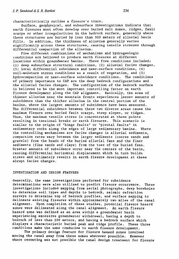
FIG. 2 View along an earth fissure trace showing the method of failure induced at a sheet piling cutoff wall intended to mitigate earth fissure development.

/. P. Sandoval & S. R. Bartlett 258
far the most successful remedial method tried to date has been the sealing of earth fissures in combination with rerouting of drainages away from the afflicted area. The intent of sealing earth fissures and diverting the drainages is to prevent surface flows from eroding the earth fissures, and creating the large gullies that are characteristic of mature earth fissures. To seal the enlarged earth fissures, combinations of clay, bentonite mixed with soil, and soil cements have been used to fill and mound up to 2 meters of material over the fissure. Rerouting of the drainage often requires several readjustments to achieve adequate results. Upon completion of any earth fissure mitigation, continued close surveillance and immediate corrections are necessary to prevent rejuvenation of the afflicted earth fissure. To test methods of mitigation, one of the sheet piling cutoff walls,
which was constructed along both sides of a paved access road, was tested to failure (Figure 2). The results of this test indicate that these cutoff wall methods can prevent immediate failure of a structure long enough to make corrective fixes. However, hairline cracks developed between of the sheet piling walls during testing which will ultimately result in failure of the road.
FUTURE EARTH FISSURE MITIGATION ON THE CAP
To coordinate earth fissure activities, a fissure hazard committee has been formed between USBR project personnel and water district personnel. The charge of this committee, is to share information on earth fissure development and monitoring, to report on remedial earth fissure treatments that can be related to CAP earth fissures, to initiate work requests for earth fissure mitigation, develop a Standard Operating Procedures (SOP) manual for earth fissure mitigation and control, and to develop future earth fissure mitigation techniques through research.
Among the earth fissure prediction techniques that look promising for future research and development are acoustic emission surveys, and extensometer monitoring techniques. To date, extensometers have been used by the USGS to monitor and predict earth fissure development with good results. No work has been accomplished to date with acoustic emissions; however, the conditions are suitable for this type of monitoring. Tensile stress buildups give off acoustic signatures and listening posts in the form of fence posts are embedded approximately every three meters along the canal perimeter to provide data points for the monitoring of these emissions.
Geophysical methods have also been tried to locate near surface earth fissure openings with some success. However, the openings must be wide enough to attenuate the refracted waves. In conjunction with the Arizona Geological Survey an attempt has been made to predict fissure development rates by using dated aerial photographs. This method has some potential; however, complete photographic records in areas of fissure development are rare.
The cornerstone of the continuing earth fissure mitigation program is the early detection and treatment of these fissure before they can enlarge and cause extensive damage to engineering structures such as the CAP. Due to the method of development of fissures (emanating from the groundwater level and migrating to the ground surface), early detection will continue to involve mapping of known traces and

259 Land subsidence and earth flssuring in Arizona
subsurface irregularities, and periodic monitoring to determine growth rates, direction, and proximity to engineering structures. The most successful methods of mitigation for the foreseeable future will involve sealing the surface trace and diverting adjacent drainage.
Efforts have been most successful in preventing damage on the mainstem of the CAP canal where the proper expertise is available and the responsible employees have been educated in the origin and destructive potential of these earth fissures. Conversely, the most troubles with earth fissure damage has been experienced on the offstream canals and distant laterals where the expertise and funding has not been available to adequately mitigate earth fissures. To be successful in the future, the education, expertise and funding must be made available to the smaller water districts to insure adequate fissure mitigation offstream from the CAP. In summary the key elements of a successful earth fissure mitigation program are education, early detection, and prompt remedial treatment.
REFERENCES
Holzer, T.L., Davis, S.N. and Lofgren, B.E. (1979) Faulting Caused by Groundwater Extraction in South Central Arizona, i. Geophys. Res. M (B2) 603-612.
Larson, M.K. and Pewe , T.L. (1986) Origin of Land Subsidence and Earth Fissuring, Northeast Phoenix, Arizona. Bull. Assoc. Eng. Geol. 23 (2) 139-162.
Schumann, (1986) Groundwater Depletion and Land Subsidence in Western Pinal County, Arizona. Focus Conference on Southwest Groundwater Issues October 20-22, 1986, Tempe Arizona Proceedings.
Schumann, H.H. and Anderson S.R. (1988) Land Subsidence Measurements and Aquifer Compaction and Monitoring in the Tucson Basin and Avra Valley, Arizona. USGS Water Resources Investigations Report 88-4167.
Slaff, S., Jackson, G.W. and Pearthree, P.A. (1989) Development of Earth Fissures in Picacho Basin, Pinal County, Arizona from 1959 to 1989. Arizona Geological Survey Open - File Report No. 89-10.
U.S. Department of the Interior, Geological Survey (1986) Geohydrologic Data along the Salt-Gila Aqueduct of the Central Arizona Project in Maricopa and Pinal Counties, Arizona. Open-File Report 86-236, Tucson, Arizona.
U.S. Department of the Interior, Geological Survey (1985) Geohydrologic Data along the Tucson Aqueduct of the Central Arizona Project in Pinal and Pima Counties, Arizona. Open-File Report 85-565, Tucson, Arizona.
U.S. Department of the Interior, Bureau of Reclamation (1985) Design Summary - Salt-Gila Aqueduct; Central Arizona Project, Arizona.
U.S. Department of the Interior, Bureau of Reclamation (1976) Geology and Groundwater Resources Report, Maricopa and Pinal Counties, Arizona. Arizona Projects Office, Phoenix, Arizona.
U.S. Department of the Interior, Bureau of Reclamation (1982) Salt-Gila Aqueduct Reach 4 - Solicitation No. 3-SB-30-00010/Specification No. DC-7527; Central Arizona Project, Arizona.
U.S. Department of the Interior, Bureau of Reclamation (1985) Subsidence and Earth Fissure Predictions for Reaches 4, 5, and 6, Tucson Aqueduct and Twin Peaks, Sandario, Brawley, San Xavier,

/. P. Sandoval & S. R. Bartlett 260
Snyder Hill, and Black Mountain Pumping Plants. Central Arizona Project, Arizona.
U.S. Department of the Interior, Bureau of Reclamation (1986) Tucson Aqueduct Reach 3 Completion and Reach 4 - Solicitation No. 6-SI-30-04380/Specification No. DC-7668; Central Arizona Project, Arizona.