Lamp Project
19
-
Upload
pete-elder -
Category
Documents
-
view
216 -
download
0
description
Given the brief of designing a task light
Transcript of Lamp Project

1.
Context:
This module focuses on the careful selection and combination of materials and processes. In this context planning every detail is crucial in avoiding the trap of sculpting a three dimesional design soloution. The term lask lighting refers to situations where the task light increases luminance of a given speciic area - perhaps the most prevalent being in an office environment where it is used to enhance the lighting effect on the reading area. CContrast is perhaps just as import as lighting intensity when trying to increase visibility, a badly positioned light source will cause a reduction in contrast and a corresponding loss of visibility. The intention of this module is to look at how well designed task lights can be used to aid/ support/ promote the act of reading. The reading of printed materials takes many forms, from getting lost in a work of iction through to glancing at headlines in newsprint to completing research for work related assignments.
This module requires the effective communication of the design process.
AAssignment:
Design a task light that is fully adjustable and capable of being posed at various angles. A further require-ment is that the light must be designed to sit on a desk.
The Brief

Contents:
Research and Initial Designs:
Pages: 3 - 13
Design Development and Modeling:
Pages: 14 - 28
Manufacturing:
Pages: 29 - 35
PhoPhotography and Feedback
Pages: 36 -
2.
Research and
Design
3.

Research
4.
On the bottom three pictures I liked the idea of having a strip light or some way of having an illumination from the base.
On this lamp I like how it was so elegant and very easy to adjust, the use of counterbalances was something I decided to look into trying to use
The majority of my research was undertook whilst I was in New York. On each of these lights I saw little parts which I liked and felt I could possibly encorperate into my nal product.
The use of metal as a main material was something I liked, and I particulalrly liked the large lampshade with the circular upright.
Research
5.
This light both looks impressive and is very easy to use. The use of very small pivot points and in some points pul-leys meant you would easily be able to change the height of the light without having to use much energy. I wasn’t as keen on the cheap looking lampshade and I lampshade and I felt this should have been made out of nicer materials such as metal
On the lamp below I liked the rigid shape of the arch. I also really like the frosted glass lampshade as the light looks really good as it disperse at different intensities.
On this light the idea of having the LED’s in the arm really appealed and look simple but effectice. the base was easy to move and the use of the pivot provided a nice contrast between each section of the light.
On this lamp I liked how the lampshade was angled and this meant it was easy to direct the light exactly where I would want to. It also looked aesthetically pleasing with how the light head morphs into the arm.

Research
6.
With this light I enjoyed how the designer had decided to make a ffeature of the wire by it being visible as it weaves through the upright and the arm. The use of wing nuts to join the upright and the arm was simple but effective. I felt the lamp shade was in keeping with the design but I would rather it was translucent as I liked the lamp shades wheliked the lamp shades where the light dispersed from all over.
This bottom light looked like it would be easy to move but turned out to be stiff, the tube had rusted slightly which put me of the idea of using it in my design. The lamp shade whilst being unnecessary was exactly the type of thing I was looking at which caused me to look to look at the use of stained glass or frosted glass in my design.
The use of springs to limit the movement was a very nice design addition, I paparticularly like the ease in which I was able to change the angle of the light. I was not particularly keen on the lamp shade as I felt it was dull and not in keeping with the rest of the desithe design of the light.
At the base of the light the use of a clamp was something I later looked into trying to utilise. I eventually decided against the clamping mechanism as it was heavily time consuming and didnt t the brief that it must sit on the table. I also felt there could be a chance that the user would damage the desdesk. Overall I liked this lamp and the way it was easy to adjust in all directions required.
Inspiration
7.
These pictures particularly inspired me whilst designing, this is because: on the wonder wheel from Coney Island I like the simple but structural shape which was something I was iinterested in achieving in my design. With the other pictures I liked how the light was able to shine through the different materials often with differing degrees of success. The stained glass window and the weird object in the top right corner made me rst think of possibly using a mood light in the design.

8. 9.

For this design I thought of using the hydraulic part of a computer chair to lower the light to the desired height. I went against this design because it looks ugly and would be very difficult to manufacture on a small scale.
On the design to the right I was inspiinspired by on of the lights on I had previously looked at. I thought that if I used ball bearings I would be able to rotate the light around so it would be veiwable in different positions whilst having more rigid arm positions.
10. 11.11.

12.
This design I thought about a way to hide the wires. The best way was to have a tube inside a tube. Once I had decided that I started to think of other things I could do from there to conceal the inside tube, the best Idea I had was to make a mood light/ Night light
Mood Light Inspiration
13.
The classic lava lamp was something which I drew inspiration from whilst desidesigning. The steel tubes either side of the lamp both look aes-thetic and draw you into what would be the mood Light.
I really like the look of these mood lights as they are cylinderical and the pattern contained is both aesthetically pleasing and is something I could possibly replicate in my product.
For this mood light, whilst I don’t like the design I like how it has been frosted and lets out a dim glow, to acheive this may be difficult but would be worth-while in trying get the centre to glow.
I liked how the light emanates out from a centre ring, and whilst I couldnt do this in my design I really liked the idea of having it shining from the underneath of my lamp or from the sides of the base.

Design Development and
Modelling
14. 15.

Whilst designing the whole product I decided thdecided that I should have a top bracket which would look aesthetically pleasing and also slightly resemble the idea of the lava lamp by adding balance in the design. I also felt the base should be rounded as this aesthetically pleaseing and would also be easy to house the OuOuter and inner tubes of the mood light.
Whilst designing the arm I focused on the idea to house everything so it was ush, I used CAD to pproduce some of my models. The design slowly evolved as I changled angles and sizes. I rounded the edges to produce a nice streamlined effect on the product. I later wondered if part of it could rotate to change the angle of the LED’s. The basis of this design was when you moved the weight, which was aattatched by magnets the angle of the arm would move. Whilst this is possible I found it would be extremely difficult to be precise in the correct angle .
16. 17.
In an attempt to get my previous design to work I looked into using a pulley system. This was because I wouldnt be able to accurately get the desired angle by moving the angle. I decided against the pulleys as I felt they would be unaesthetic and I could design something better.
IIt was at this stage I started to mess around with the arm to come up with a new design for that which I would rather make and would look good. I settled on a straight but tubular design. This both looked unique and provided something I felt other lights in the market couldn’t. The ability to angle the light was something which pleased me, this combined with the angle of the light meant that it would brighten a slightly larger area but provide the cocontrast to help the user read.
I also changed the base to add more balance in the design, once again taking inspiration from the lava lamp I previously looked at.

18.
On this page I tried to model the lamp using solidworks. Whilst doing this I veiwed it from different angles and out of a range of materials and nishes. Personally I prefered the use of ccontrasting colours. My favourite use of colours was to use red and black as nishes, these could be spray painted on if I was to use Beech or powder coated if I use aluminium. I also started to consider Plastic as this would mean I wouldn’t need to add a nish after making. Other colours which particulalry excited me was the use of blue with silver. I liked the contrast in materials between beech and brass but I wasn’t the biggest fan of a nnatural nish and I decided that I would rather have a satin nish than a very glossy nish.
AAfter this modeling where I used xed dimensions which I slowly changed to change the look I decided that the on off switch at the end wasn’t particularly aesthetically pleasing and I should try changing my design to encorparate something which would suit the rest of the design a lot better. I also thought about the cradle and how it could be improved to be more inkeeping with the rest of the design.
19.
To the right is what I settled upon as my nal idea for the bracket, in this design it allows rotation around the mood lamp and has space for all the parts to t together. Their is a hole for the wire to enter the arm and has been designed so the mood lighting tube is easily able to slot into the top bracket. I got the idea to slant the angle from some nigsome night lights on my walk home one night.
The changling of the bracket was loosely based on the look of a microphone stand. Although I decided against pivoting the light this would be an option in the future.

20.
The manufacturing of the top bracket is very complex. It is made up of 4 peices which are attatched together in a particular way. Part 1 is slid inside Part 4. This enables the rotaion of the arm. Part 2 is then attatched to the arm on the groove specially made for it. Part 2 is then attatched to Part 1 in the groove made for that.TThen you apply a washer to the base of Part 1 and join Part 3 to Part 4. The washer enables the arm to be rotated easily.
Finally the base of the bracket is cut into an angle to create the desired shape.
TTo manufacture these peices I am going to use the lathe as this would be the most appropriate due to the shapes. Due to the cost of materials I plan on making this out of beech as it would create a suitable nish straight away and wouldn’t have to be varnished, something I am opposed to doing.
Part 1
Part 2
Part 3
Part 4
The model I made is shown to the right. I was able to use all the processes which I plan on using and the nish looks aesthetically pleasing.
21.
Part 1
Part 2
Part 3
Part 4
Parts 1 & 2
Parts 3 & 4
Part 1 slots into Part 2 and is glued in place. Housed in Part one is the On/Off switch. Part 3 is then attatched to Part 4 in the same way as Parts 1 and 2. This is made easier due to there being a recess for the wood to slot ttogether. The new part then has an angled cut put in to make the lamp shade. Housed in this part is the whole circuit for the main lamp.Part 3 is then attatched to Part 2 so that the arm is able to rotate around.AAround Part 2 is the bracket which allows the rotation. Finally the On/Off switch is housed in the part I have made for it.

22.
LED’s
Inner Tube
Mood Light
As you can see on this picture, the tubes are suitably housed in side the suitably housed in side the top bracket and the Base. The Base needs to be slightly altered to allow the wires and LED’s to be housed inside. Above the inside tube is a hole where the wires are able to enter the main light. The power supply will enter the light at the base and then proceed up the light to the On/Off three-way switch.
The main lighting element produces a lot of light as shown by my testing. This made me decide against housing right at the angle on the arm but to house it slightly inside in the tube. This also would stop any user potentially burning their hand which would be a hazard. By housing the liglighting element inside the arm it also means it will act as a lamp shade which is something I think will look aesthetically pleasing whilst not blinding the userDue to the high amount of heat produced by the lamp I will also produce a heat sink to contain some of the heat although I may need to drill holes in my light’s arm to allow the heat to escape and stop it potentially scorching the beech wood.
Main light housed here
Top Bracket
These two parts were purchased due to the inability to manufacture these parts. Shown are the pictues of these parts.
23.23.22.

24.
This page shows how the two arm sections are made. They have to be made from different sections because I can’t get the parts created to their full size due to not having drill bits long enough and the section which has the top bracket attatched to it need to be made separate at the bebeginning to allow me top join the parts together without having to have and obvious join.
25.24. 25.

To the right are the parts that I must manufacture to create the top bracket. This will allow me to maufacture eaxactly how I want to whilst providing the movement required.
26.
To manufacture the Base of the light I plan on using the wood lathe to create its beautifully curved body. I will then carve it out in steps to allow room for the LED’s to sit in the base and to allow it too cool whilst also allallowing all the wires to be easily housed. I then will add a protective base to stop the wires getting in the way. Once again this is to be made out of beech.
27.26. 27.

28.
Whilst designing the on off switch I wanted to create an object which was simple in design but highly effective. At rst I thought about having the on off switch as a disk which would slightly rotate, due to this not being obvious enough I looked to incorporate having grooves to make turning easier. Whilst looking into this, using solidowrks to model the ccomponents I felt it looks better with less grooves. I looked at having a completely domed switch which felt like it completed my design. When I modelled it though I felt it would be unnecesary and wouldn’t look as aestheticlly pleasing when made out of beech. I decided pleasing when made out of beech. I decided to try adding a llet to a plain piece of beech, this looked extremely good and would be nice to look simple with the user easily able to have a secretive way of turning the light on. Using a three way switch I designed for the centre to be “off” and the rotations to turn on either the mood light or the actual main task light.
Manufacturing
29.28.

Using my cutting list I cut all the bits of Beech to the correct sizes using the table saw and the band saw. This would mean they were easier to t on the chuck as they were square and would be properly clamped in place. On each peice I then drew the centre point so I could push the centre on the lathe to the point I had marked and this would ensure the wood spun concentrically and wouldn’t y off when under pres-susure. I used the cutting tool to round off all the corners to make a cylinder. I marked off the different sections where the thicknesses would need to be changed.
Next I turned down this beech rod to the rst section (this is the part which allows the rotation of the arm). This was done very accurately by folowing my working drawings and taking of small amounts at a time as I wanted a snug t. I changed cutting tool to add the groove where the rubber/nylon ring would sit as this was the correct size in width (5mm) and was easy to turn down to the correct size.
30.
Using the same tool I turned down the other end. Firstly I turned the part which is connected to the top bracket. This was so there was going to be a tight t and because it was the larger part. I used callipers to ensure it was the correct size.I nished this pieI nished this piece by turning the very end which ts to-gether with the back end of the lamp (where the switch is housed. I then drilled down the centre to allow the wires to be housed inside my arm.
31.
I started the top bracket by turning the main tube down to the correct width plus a little bit of leeway. Slowly I turned the centre down by using bigger drill bits each time. I did this to stop the chances of burning and damaging both the drill bit and the wood. Finally I turned the centre to the de-sired width (50mm diameter). I created a bung out of some left over foam to put in the end of the wood, this was to sstop it potentially snapping whilst I tapered the edge and also to keep the wood spinning concentrially.
I angled the cutting blade so I would be able to taper the edge to create the uid shape of the top bracket. To help me do this I slowly cut out the remaining material and then chamfered the top. When there was only a few millimeters left I stoped the chamfer and decided to sand to give a good nish.TTo do this I used sandpaper and turned the lathe on, as it spun it sanded the wood to produce a good nish, I went up the grades of paper to create the best possible nish. This also meant I could apply a laquer or an oil to complete the project. I then parted this piece off. Using the disk sander I angled the base of the bracket.
With this piece now completed I made the inside of the bracket. This was all done using the cutting tool to take the width of the wood. Once I had cheched the size was correct I stopped reducing width and drilled down the centre to allow my inner tube to slot inside the bracket. I then lightly sanded the inside to remove all excess burrs but the nish was not as important as the outside as you can’t access it. I then then repeated the process to create the smaller inside part which allowed the rotation.
30. 31.
32.
I made my heat sink out of a small copper piece. I needed to make this part because of the high amount of heat the LED module dispersed. Using a saw i cut the copper to the correct shape, to make it t into the arm I made small folded aps which would slip into the lights arm and rmly attach to stop any movement. I put my LED module on the heat sink and tested it to see how hot the heat sink would bebe. It would be dangerous if it reached over 70 degrees Celsius, but it stabilised out around 60.
I tested that both the circuit and the light module would t into the arm. Once it was attatched in and the arm was made I decided I didnt like the look of my heat sink and decided to change the design to make it closer to the angle as this would brighten it up. This time I used some brass which t into a pre-made curve. Once this was in place I folded the brass over to slip inside the arm to keep it in plait in place. Using epoxy resin I joined both the heat sink and the arm together.
After turning the beech square down to a circle I made it a few mm bigger than I needed for when I nally turned it down. Using a progression of drill bits which slowly got bigger I made the inside cavity to the correct size based on my working drawing. Once the inside hole was at the correct width and thickness I added the small inside sesection to allow the other half of the arm to slot in place. This was done using a 35mm drill piece. Now that the end of my arm was done I inserted my electronics into the other section of the arm, this allowed me to make sure that everything t and was ready to be attached
I lavishly applied PVA glue to both the male and female parts of the arms and slotted the pieces together. Using the centre to slightly clamp the wood I tightened it up to ensure it was a snug nish. I used a damp cloth to remove the excess pva which had been ejected from my joint. I left the arm to dry over night.OnOnce it was dry I brought the arm down to its correct size using the cutting tool. Once satis ed I used sandpaper to smooth out the arm so it was smooth and ready to have a nish applied. I went up the grades of paper to get the best nish available, I then moved onto the wet and dry as I wanted the option of leaving the beech untreated if I couldn’t nd a nish I liked. I then added the angle to the end of the lamend of the lamp. This is when I tested the light and decid-ed to make a new heatsink to brighten it.
33.33.32.
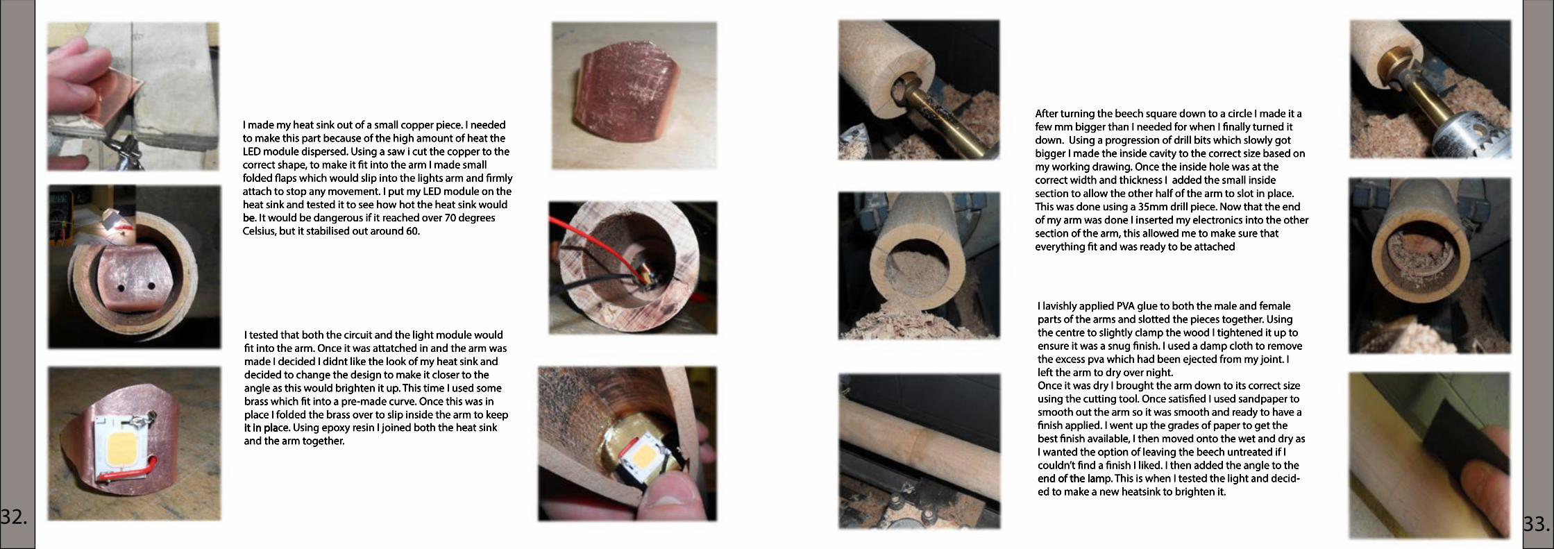
For my base I cut the peices into the correct size. Using PVA glue I bonded the sections together, I left to dry over night. I then cut the corners off to make it easier as I turned the shape on the lathe. I attatched the base to the chuck using screws and attached it to the lathe.
I turned the wood to create the correct shape which I wanted. This was made problematic due to the difficult shape of the base but I persevered. Once the base was de-signed into the correct shape I hollowed it out to place my circuit board in place by using the drill peice then used the lathe chisel to create the correct shape.
I used sandpaper and wet and dry to create a very smooth nish to the touch. This would then allow me to add a nish. I then drilled holes for the LED’s to t and the tubes. Once I had done this I started to assemble my product. I slotted my tubes together and glued them in place. I threaded my wires in place at the top of the tube ready to be nally attatched.
34.
Photography and
Feedback
35.34.

Whilst I am happy with my product I feel that it could be improved in many ways, but that I would say is the curse of the designer. There are certain things I would change to make it better, I would design it using ball bearings to allow the movements as this would enable an easier movement. The acrylic tube would be made out of frosted glass as this is a nicer material and would produce a better finish. I would also look at the use of materials, whilse I am happy with the look of the beech it might be nicer if there was a contrast of materials as this would provide a better finish. If it was to be mass produced I feel it should be made out of more common materilas for lights; such as powder coated aluminium or injection moulded plastics. I also feel the light should be scaled down.
Peter ElderCandello Designer
Whilst I am happy with the form I think it would be interesting to have expanded the range of models to analyise the variations between height and width and the positioning of the main task light. I would also like to explore the range of materials and/or finishes to expand the choices to clients if this was to be commercially available and how this would be acheived. As a prototype this is a fully functioning light and with some minor alterations it could be a success. I think if the main light had some form of filter the applications could be expanded whilst also being safer by not having the LED module exposed.
Iain Jones, Design Student
I think this light has the chance to be something unique, the ability to have it as a mood light or a task light without cheapening the design is something that Peter can take pride in. With all that said I feel the length of the arm should be adjusted as it is too long and would look better if it was shorter. In doing this the height would also need to be reduced as without a pivot to change the angle of projection it is very far from a desks surface. If there was to be a “Candella 2” I would recommend changing the proportions and trying to add a pivot at the top bracket. The ability to move the light is rigid and is a shame as it would have been easy to produce something which provided a better movement. Personally I like the width af the mood light and of the arm but as I previously said it is very big and would look out of place on a small desk. I love the finish of the beech but feel it would be nicer if there was contrast in materials.
Will FoggDesign Student
36.