
LAMBDA Schlauchpumpen Bedienungsanleitung · 2018-04-17 · LAMBDA Peristaltic Pumps User Manual 1...
34
LAMBDA Peristaltic Pumps PRECIFLOW, MULTIFLOW, HiFLOW, MAXIFLOW & MEGAFLOW OPERATION MANUAL LAMBDA Peristaltic Pumps LAMBDA PRECIFLOW, MULTIFLOW, HiFLOW, MAXIFLOW & MEGAFLOW
Transcript of LAMBDA Schlauchpumpen Bedienungsanleitung · 2018-04-17 · LAMBDA Peristaltic Pumps User Manual 1...
LAMBDA Peristaltic Pumps PRECIFLOW, MULTIFLOW, HiFLOW, MAXIFLOW & MEGAFLOW
OPERATION MANUAL
LAMBDA Peristaltic Pumps
LAMBDA PRECIFLOW, MULTIFLOW, HiFLOW, MAXIFLOW & MEGAFLOW
LAMBDA Peristaltic Pumps User Manual
www.lambda-instruments.com www.peristaltic-pump.eu 1
LAMBDA Peristaltic Pump – Tubing Pump
The LAMBDA peristaltic pumps have been specially developed for continuous cultures as
the result of over twenty years of laboratory experience and involved the systematic
elimination of the imperfections found in other pumps on the market.
The successful design and well-proved mechanics of the LAMBDA PRECIFLOW pump has
been extended by flow rate programming. Up to 99 steps of time and flow rate can be easily
programmed, thus allowing the creation of any desired flow rate profile. The maximum flow rate
has been increased to up to 60,000 ml/hour. Until now, it was not possible to produce peristaltic
pumps with such a high flow rate in such a small instrument casing.
LAMBDA Laboratory Instruments
LAMBDA Laboratory Instruments is the developer and manufacturer of LAMBDA laboratory
instruments that are commercially available worldwide. LAMBDA laboratory instruments are
specially developed for research laboratories and process optimization and are used for
long term applications in chemical, pharmaceutical, biotechnology, microbiology and food
technology industries.
LAMBDA PRECIFLOW, MULTIFLOW, HIFLOW, MAXIFLOW & MEGAFLOW peristaltic
pumps – Reliable, precise, extremely compact and stackable
LAMBDA MINIFOR – Highly innovative and compact fermenter and bioreactor system for
laboratory scale fermentation and cell cultures
LAMBDA OMNICOLL – Automated fraction collector-sampler for unlimited number of fractions
LAMBDA DOSER / HI-DOSER – Automatic feeding of powders without spoon. Safe operation
with hazardous material (GLP) and GMP
LAMBDA VIT-FIT/ VIT-FIT HP polyvalent syringe pump with extremely robust mechanics –
programmable infusion and filling from micro syringes to large volume syringes of 150 ml without
adapter
LAMBDA MASSFLOW – Precise gas flow measurement and control with data acquisition
option
LAMBDA PUMP-FLOW INTEGRATOR – Embedded within LAMBDA pumps and doser allows
the visualization and recording of the pumped volume
LAMBDA Peristaltic Pumps User Manual
www.lambda-instruments.com www.peristaltic-pump.eu 2
Table of contents
1 SETTING UP THE PERISTALTIC PUMP ................................................................. 3
1.1 Tubing installation ................................................................................................... 3 1.2 Pump ON/OFF ........................................................................................................ 5 1.3 Pump flow rate ........................................................................................................ 5 1.4 Selecting flow direction ............................................................................................ 6 1.5 Fast filling / Emptying the line .................................................................................. 6 1.6 FAS / SLO mode of MEGAFLOW pump .................................................................. 7
2 PROGRAMMING LAMBDA PERISTALTIC PUMPS ............................................... 8
2.1 Programming mode of peristaltic pumps ................................................................. 8 2.2 Start the program ...................................................................................................12 2.3 Review program .....................................................................................................12
3 PERISTALTIC PUMP FLOW CALIBRATION ........................................................ 13
3.1 Volumetric calibration of pump flow rate .................................................................13 3.2 Calibration of pump flow rate by weight ..................................................................14
4 REMOTE CONTROL OF LAMBDA PUMPS .......................................................... 15
4.1 ON/OFF remote control ..........................................................................................15 4.2 Analog remote control of pump speed ....................................................................15 4.3 Digital remote control of pump via PC ....................................................................16
5 PRACTICAL ADVICES ON USING PERISTALTIC PUMP .................................... 16
6 FOR YOUR SAFETY IN HANDLING PUMPS ........................................................ 17
7 CONSTRUCTION ADVANTAGES OF LAMBDA PERISTALTIC PUMPS ............. 18
7.1 Construction of the pump head...............................................................................18 7.2 High quality Swiss motor and microprocessor ........................................................18 7.3 Handy construction of LAMBDA peristaltic pumps ..................................................18 7.4 In-built remote control options ................................................................................19 7.5 Programmable peristaltic pumps ............................................................................19
8 FLOW DIAGRAM OF LAMBDA PERISTALTIC PUMPS ....................................... 19
8.1 Flow diagram of PRECIFLOW & MULTIFLOW .......................................................20 8.2 Flow diagram of HiFLOW peristaltic pump .............................................................21 8.3 Flow diagram of MAXIFLOW peristaltic pump ........................................................22 8.4 Flow rate of MEGAFLOW peristaltic pump .............................................................23
9 APPLICATION OF LAMBDA PERISTALTIC PUMPS ........................................... 23
10 TECHNICAL SPECIFICATION OF LAMBDA PUMPS ....................................... 24
10.1 General specifications of LAMBDA laboratory peristaltic pumps.............................24 10.2 Remote control (Inputs/Outputs) of LAMBDA peristaltic pumps ..............................26 10.3 Input (12 V DC) of LAMBDA peristaltic pump .........................................................26
11 ACCESSORIES AND SPARE PARTS FOR LAMBDA PUMPS ......................... 27
11.1 LAMBDA INTEGRATOR for Pumps (Art. No. 4803) ...............................................27 11.2 PNet PC control software for LAMBDA dosing units (Art. No. 6600) .......................27 11.3 List of accessories and spare parts for LAMBDA peristaltic pumps ........................27
12 APPENDIX .......................................................................................................... 29
12.1 RS communication protocol for LAMBDA peristaltic pumps ....................................29 12.2 RS communication protocol for the on-board PUMP-FLOW INTEGRATOR (optional)
30
13 GUARANTEE ON LABORATORY PUMPS ........................................................ 33
LAMBDA Peristaltic Pumps User Manual
www.lambda-instruments.com www.peristaltic-pump.eu 3
1 SETTING UP THE PERISTALTIC PUMP
A short video of the peristaltic pump installation can be viewed online at www.lambda-
instruments.com/peristaltic-pumps/#video.
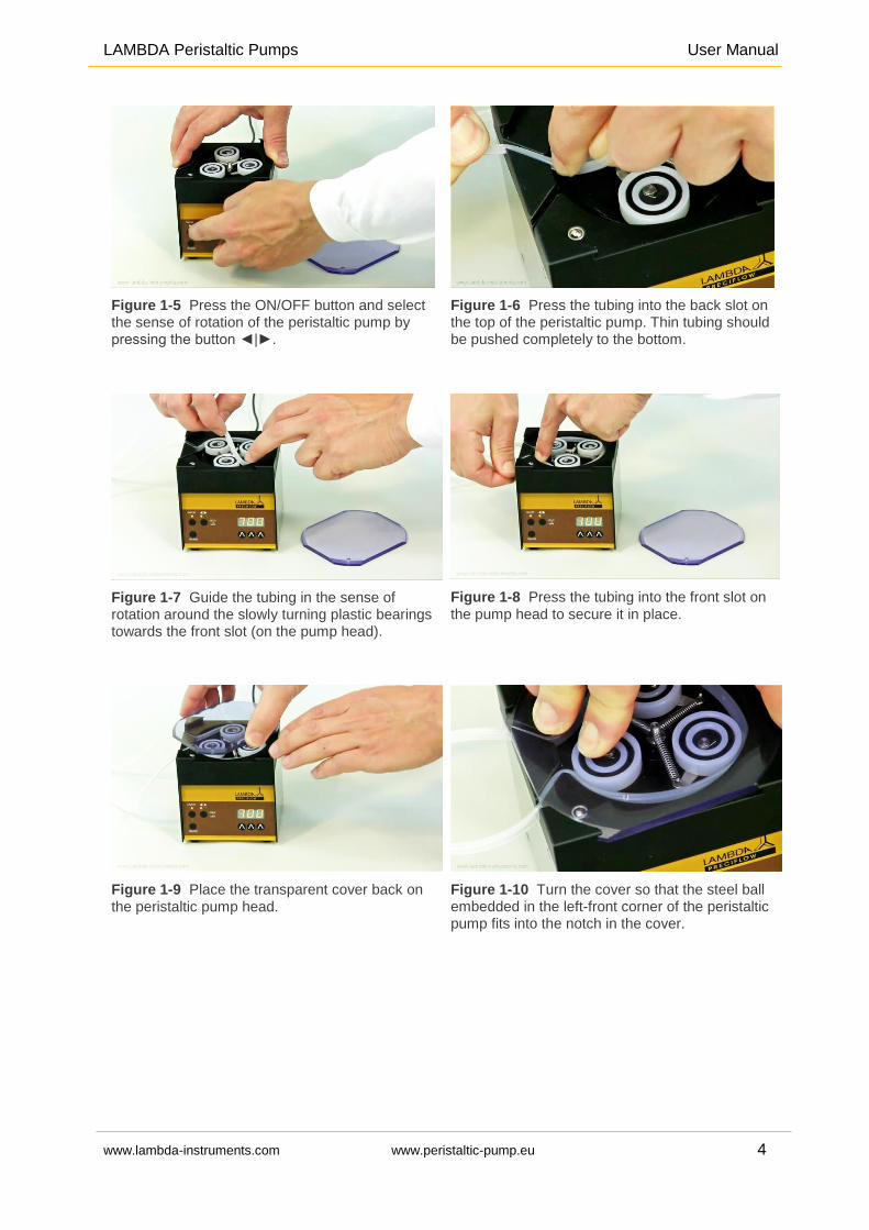
1.1 Tubing installation
While inserting the tubing on the pump head, care should be taken not to get the fingers clamped by the rollers.
Press the tubing to the bottom of slot, when inserting and fixing the pump tubing on the pump head. The correct position of the tubing is important, especially in-case of thin pump tubing.
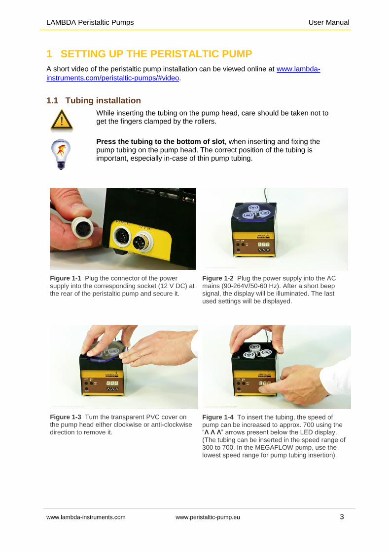
Figure 1-1 Plug the connector of the power supply into the corresponding socket (12 V DC) at the rear of the peristaltic pump and secure it.
Figure 1-2 Plug the power supply into the AC mains (90-264V/50-60 Hz). After a short beep signal, the display will be illuminated. The last used settings will be displayed.
Figure 1-3 Turn the transparent PVC cover on the pump head either clockwise or anti-clockwise direction to remove it.
Figure 1-4 To insert the tubing, the speed of pump can be increased to approx. 700 using the “Λ Λ Λ” arrows present below the LED display. (The tubing can be inserted in the speed range of 300 to 700. In the MEGAFLOW pump, use the lowest speed range for pump tubing insertion).
LAMBDA Peristaltic Pumps User Manual
www.lambda-instruments.com www.peristaltic-pump.eu 4
Figure 1-5 Press the ON/OFF button and select the sense of rotation of the peristaltic pump by pressing the button ◄|►.
Figure 1-6 Press the tubing into the back slot on the top of the peristaltic pump. Thin tubing should be pushed completely to the bottom.
Figure 1-7 Guide the tubing in the sense of rotation around the slowly turning plastic bearings towards the front slot (on the pump head).
Figure 1-8 Press the tubing into the front slot on
the pump head to secure it in place.
Figure 1-9 Place the transparent cover back on
the peristaltic pump head.
Figure 1-10 Turn the cover so that the steel ball embedded in the left-front corner of the peristaltic pump fits into the notch in the cover.
LAMBDA Peristaltic Pumps User Manual
www.lambda-instruments.com www.peristaltic-pump.eu 5
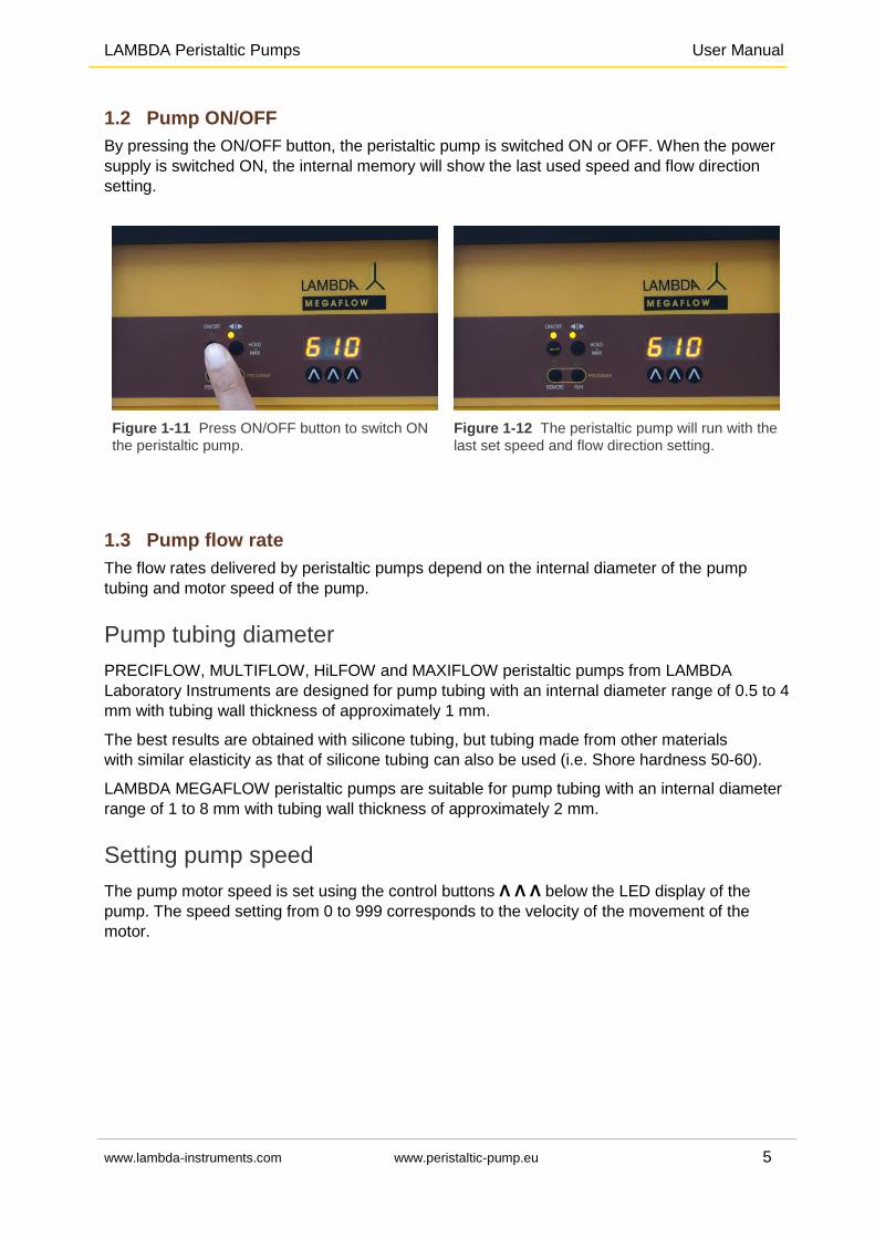
1.2 Pump ON/OFF
By pressing the ON/OFF button, the peristaltic pump is switched ON or OFF. When the power
supply is switched ON, the internal memory will show the last used speed and flow direction
setting.
Figure 1-11 Press ON/OFF button to switch ON
the peristaltic pump.
Figure 1-12 The peristaltic pump will run with the
last set speed and flow direction setting.
1.3 Pump flow rate
The flow rates delivered by peristaltic pumps depend on the internal diameter of the pump
tubing and motor speed of the pump.
Pump tubing diameter
PRECIFLOW, MULTIFLOW, HiLFOW and MAXIFLOW peristaltic pumps from LAMBDA
Laboratory Instruments are designed for pump tubing with an internal diameter range of 0.5 to 4
mm with tubing wall thickness of approximately 1 mm.
The best results are obtained with silicone tubing, but tubing made from other materials
with similar elasticity as that of silicone tubing can also be used (i.e. Shore hardness 50-60).
LAMBDA MEGAFLOW peristaltic pumps are suitable for pump tubing with an internal diameter
range of 1 to 8 mm with tubing wall thickness of approximately 2 mm.
Setting pump speed
The pump motor speed is set using the control buttons Λ Λ Λ below the LED display of the
pump. The speed setting from 0 to 999 corresponds to the velocity of the movement of the
motor.
LAMBDA Peristaltic Pumps User Manual
www.lambda-instruments.com www.peristaltic-pump.eu 6
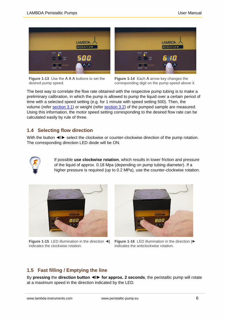
Figure 1-13 Use the Λ Λ Λ buttons to set the desired pump speed.
Figure 1-14 Each Λ arrow key changes the corresponding digit on the pump speed above it.
The best way to correlate the flow rate obtained with the respective pump tubing is to make a
preliminary calibration, in which the pump is allowed to pump the liquid over a certain period of
time with a selected speed setting (e.g. for 1 minute with speed setting 500). Then, the
volume (refer section 3.1) or weight (refer section 3.2) of the pumped sample are measured.
Using this information, the motor speed setting corresponding to the desired flow rate can be
calculated easily by rule of three.
1.4 Selecting flow direction
With the button ◄Ι► select the clockwise or counter-clockwise direction of the pump rotation.
The corresponding direction LED diode will be ON.
If possible use clockwise rotation, which results in lower friction and pressure
of the liquid of approx. 0.18 Mpa (depending on pump tubing diameter). If a
higher pressure is required (up to 0.2 MPa), use the counter-clockwise rotation.
Figure 1-15 LED illumination in the direction ◄|
indicates the clockwise rotation.
Figure 1-16 LED illumination in the direction |►
indicates the anticlockwise rotation.
1.5 Fast filling / Emptying the line
By pressing the direction button ◄Ι► for approx. 2 seconds, the peristaltic pump will rotate
at a maximum speed in the direction indicated by the LED.
LAMBDA Peristaltic Pumps User Manual
www.lambda-instruments.com www.peristaltic-pump.eu 7
After releasing the direction button, the pump stops pumping the liquid.
This "HOLD = MAX" function is used to fill the tubing before the actual dosing or to empty the
tubing line at the end of the lab experiment.
The "HOLD = MAX" function can also be used even if ON/OFF button has not been pressed.
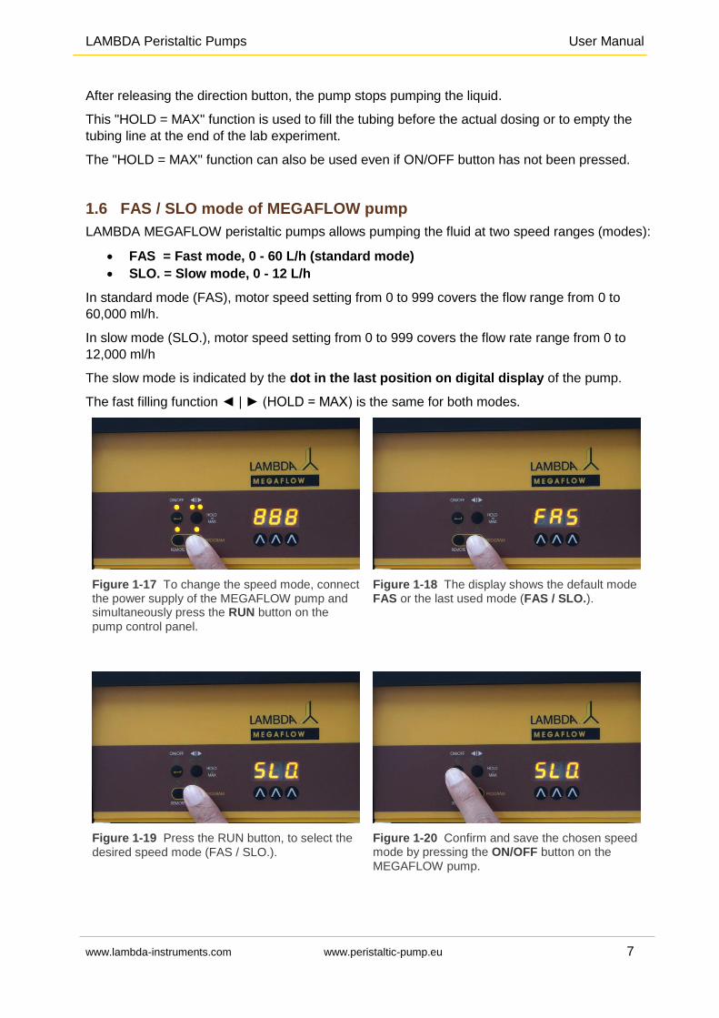
1.6 FAS / SLO mode of MEGAFLOW pump
LAMBDA MEGAFLOW peristaltic pumps allows pumping the fluid at two speed ranges (modes):
FAS = Fast mode, 0 - 60 L/h (standard mode)
SLO. = Slow mode, 0 - 12 L/h
In standard mode (FAS), motor speed setting from 0 to 999 covers the flow range from 0 to
60,000 ml/h.
In slow mode (SLO.), motor speed setting from 0 to 999 covers the flow rate range from 0 to
12,000 ml/h
The slow mode is indicated by the dot in the last position on digital display of the pump.
The fast filling function ◄ | ► (HOLD = MAX) is the same for both modes.
Figure 1-17 To change the speed mode, connect the power supply of the MEGAFLOW pump and simultaneously press the RUN button on the
pump control panel.
Figure 1-18 The display shows the default mode FAS or the last used mode (FAS / SLO.).
Figure 1-19 Press the RUN button, to select the
desired speed mode (FAS / SLO.).
Figure 1-20 Confirm and save the chosen speed mode by pressing the ON/OFF button on the
MEGAFLOW pump.
LAMBDA Peristaltic Pumps User Manual
www.lambda-instruments.com www.peristaltic-pump.eu 8
Remark: During the RS-communication, only the value shown on the display is transferred, but
not the speed range (mode). If the PUMP-FLOW INTEGRATOR is activated (optional), a single
integrator step is independent of the set speed (mode).
2 PROGRAMMING LAMBDA PERISTALTIC PUMPS
A short video on programming the LAMBDA peristaltic pumps can be found at: www.lambda-
instruments.com/peristaltic-pumps/#video
Up to 99 pairs of time and speed setting (flow rate) can be programmed on locally on the pump
display of LAMBDA MULTIFLOW, HiFLOW, MAXIFLOW und MEGAFLOW peristaltic pumps
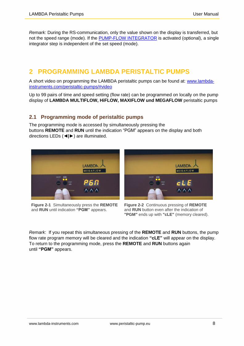
2.1 Programming mode of peristaltic pumps
The programming mode is accessed by simultaneously pressing the
buttons REMOTE and RUN until the indication “PGM” appears on the display and both
directions LEDs (◄|►) are illuminated.
Figure 2-1 Simultaneously press the REMOTE and RUN until indication “PGM” appears.
Figure 2-2 Continuous pressing of REMOTE and RUN button even after the indication of "PGM" ends up with "cLE" (memory cleared).
Remark: If you repeat this simultaneous pressing of the REMOTE and RUN buttons, the pump
flow rate program memory will be cleared and the indication “cLE” will appear on the display.
To return to the programming mode, press the REMOTE and RUN buttons again
until “PGM” appears.
LAMBDA Peristaltic Pumps User Manual
www.lambda-instruments.com www.peristaltic-pump.eu 9
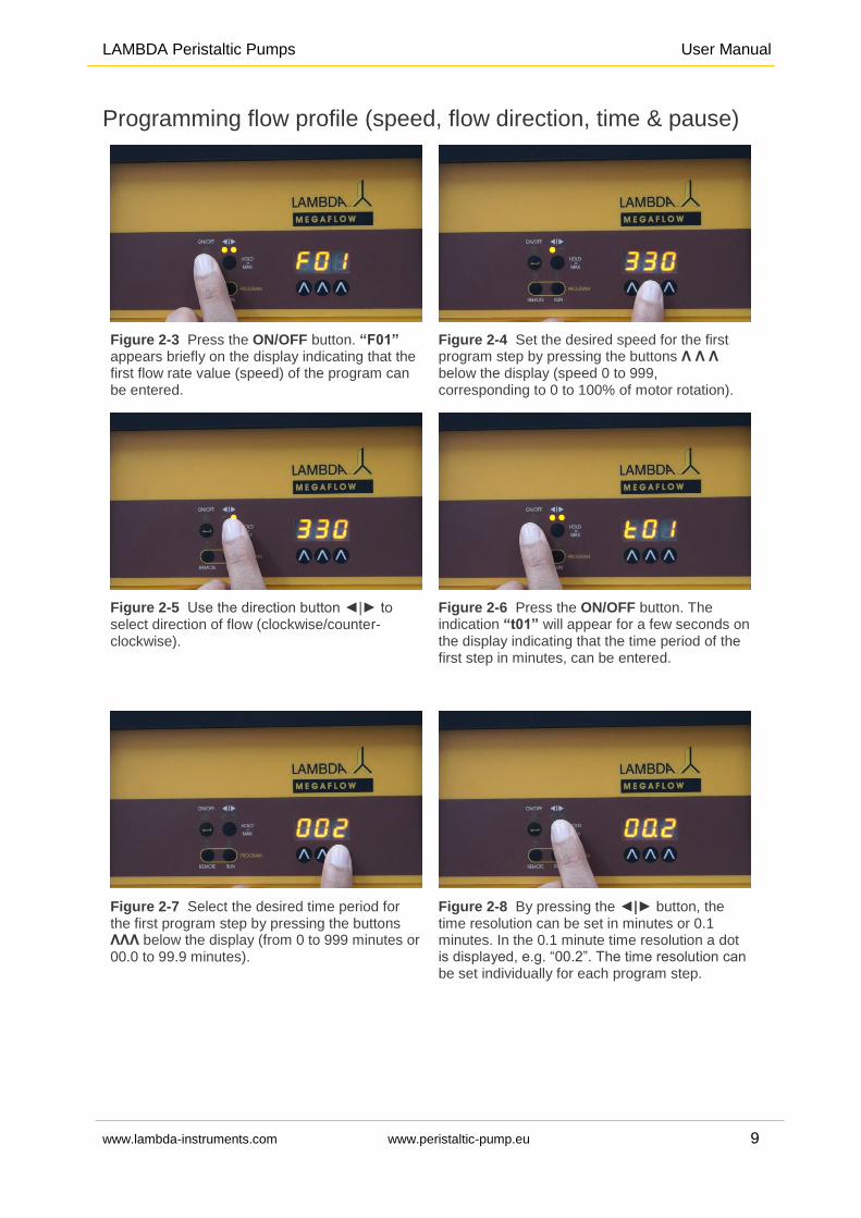
Programming flow profile (speed, flow direction, time & pause)
Figure 2-3 Press the ON/OFF button. “F01” appears briefly on the display indicating that the first flow rate value (speed) of the program can be entered.
Figure 2-4 Set the desired speed for the first program step by pressing the buttons Λ Λ Λ below the display (speed 0 to 999, corresponding to 0 to 100% of motor rotation).
Figure 2-5 Use the direction button ◄|► to select direction of flow (clockwise/counter-clockwise).
Figure 2-6 Press the ON/OFF button. The indication “t01” will appear for a few seconds on the display indicating that the time period of the first step in minutes, can be entered.
Figure 2-7 Select the desired time period for the first program step by pressing the buttons ΛΛΛ below the display (from 0 to 999 minutes or 00.0 to 99.9 minutes).
Figure 2-8 By pressing the ◄|► button, the time resolution can be set in minutes or 0.1 minutes. In the 0.1 minute time resolution a dot is displayed, e.g. “00.2”. The time resolution can be set individually for each program step.
LAMBDA Peristaltic Pumps User Manual
www.lambda-instruments.com www.peristaltic-pump.eu 10
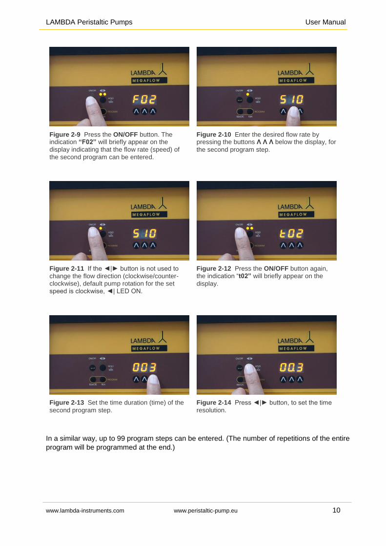
Figure 2-9 Press the ON/OFF button. The indication “F02” will briefly appear on the display indicating that the flow rate (speed) of the second program can be entered.
Figure 2-10 Enter the desired flow rate by pressing the buttons Λ Λ Λ below the display, for
the second program step.
Figure 2-11 If the ◄|► button is not used to change the flow direction (clockwise/counter-clockwise), default pump rotation for the set speed is clockwise, ◄| LED ON.
Figure 2-12 Press the ON/OFF button again, the indication “t02” will briefly appear on the
display.
Figure 2-13 Set the time duration (time) of the
second program step.
Figure 2-14 Press ◄|► button, to set the time
resolution.
In a similar way, up to 99 program steps can be entered. (The number of repetitions of the entire
program will be programmed at the end.)
LAMBDA Peristaltic Pumps User Manual
www.lambda-instruments.com www.peristaltic-pump.eu 11
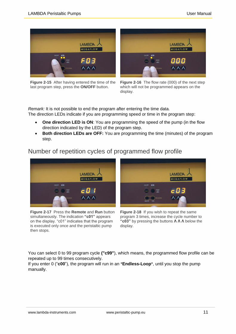
Figure 2-15 After having entered the time of the last program step, press the ON/OFF button.
Figure 2-16 The flow rate (000) of the next step which will not be programmed appears on the display.
Remark: It is not possible to end the program after entering the time data.
The direction LEDs indicate if you are programming speed or time in the program step:
One direction LED is ON: You are programming the speed of the pump (in the flow
direction indicated by the LED) of the program step.
Both direction LEDs are OFF: You are programming the time (minutes) of the program
step.
Number of repetition cycles of programmed flow profile
Figure 2-17 Press the Remote and Run button simultaneously. The indication “c01” appears on the display. “c01” indicates that the program is executed only once and the peristaltic pump then stops.
Figure 2-18 If you wish to repeat the same program 3 times, increase the cycle number to “c03” by pressing the buttons Λ Λ Λ below the
display.
You can select 0 to 99 program cycle ("c99"), which means, the programmed flow profile can be
repeated up to 99 times consecutively.
If you enter 0 (“c00”), the program will run in an *Endless-Loop*, until you stop the pump
manually.
LAMBDA Peristaltic Pumps User Manual
www.lambda-instruments.com www.peristaltic-pump.eu 12
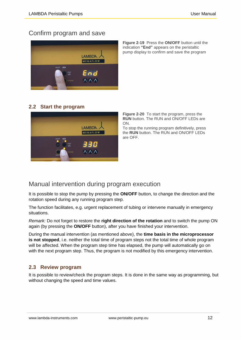
Confirm program and save
Figure 2-19 Press the ON/OFF button until the indication “End” appears on the peristaltic
pump display to confirm and save the program
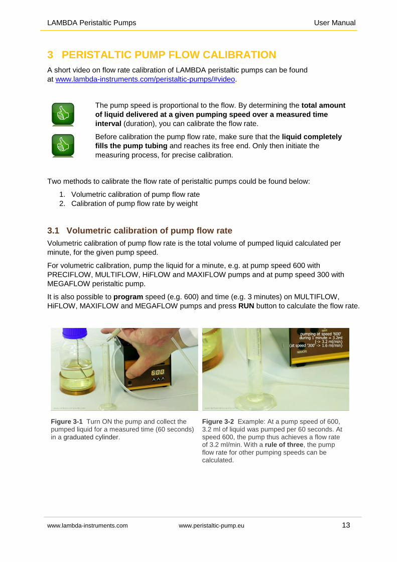
2.2 Start the program
Figure 2-20 To start the program, press the RUN button. The RUN and ON/OFF LEDs are ON. To stop the running program definitively, press the RUN button. The RUN and ON/OFF LEDs
are OFF.
Manual intervention during program execution
It is possible to stop the pump by pressing the ON/OFF button, to change the direction and the
rotation speed during any running program step.
The function facilitates, e.g. urgent replacement of tubing or intervene manually in emergency
situations.
Remark: Do not forget to restore the right direction of the rotation and to switch the pump ON
again (by pressing the ON/OFF button), after you have finished your intervention.
During the manual intervention (as mentioned above), the time basis in the microprocessor
is not stopped, i.e. neither the total time of program steps not the total time of whole program
will be affected. When the program step time has elapsed, the pump will automatically go on
with the next program step. Thus, the program is not modified by this emergency intervention.
2.3 Review program
It is possible to review/check the program steps. It is done in the same way as programming, but
without changing the speed and time values.
LAMBDA Peristaltic Pumps User Manual
www.lambda-instruments.com www.peristaltic-pump.eu 13
3 PERISTALTIC PUMP FLOW CALIBRATION
A short video on flow rate calibration of LAMBDA peristaltic pumps can be found
at www.lambda-instruments.com/peristaltic-pumps/#video.
The pump speed is proportional to the flow. By determining the total amount
of liquid delivered at a given pumping speed over a measured time
interval (duration), you can calibrate the flow rate.
Before calibration the pump flow rate, make sure that the liquid completely
fills the pump tubing and reaches its free end. Only then initiate the
measuring process, for precise calibration.
Two methods to calibrate the flow rate of peristaltic pumps could be found below:
1. Volumetric calibration of pump flow rate
2. Calibration of pump flow rate by weight
3.1 Volumetric calibration of pump flow rate
Volumetric calibration of pump flow rate is the total volume of pumped liquid calculated per
minute, for the given pump speed.
For volumetric calibration, pump the liquid for a minute, e.g. at pump speed 600 with
PRECIFLOW, MULTIFLOW, HiFLOW and MAXIFLOW pumps and at pump speed 300 with
MEGAFLOW peristaltic pump.
It is also possible to program speed (e.g. 600) and time (e.g. 3 minutes) on MULTIFLOW,
HiFLOW, MAXIFLOW and MEGAFLOW pumps and press RUN button to calculate the flow rate.
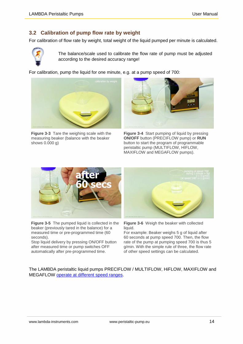
Figure 3-1 Turn ON the pump and collect the pumped liquid for a measured time (60 seconds) in a graduated cylinder.
Figure 3-2 Example: At a pump speed of 600, 3.2 ml of liquid was pumped per 60 seconds. At speed 600, the pump thus achieves a flow rate of 3.2 ml/min. With a rule of three, the pump flow rate for other pumping speeds can be calculated.
LAMBDA Peristaltic Pumps User Manual
www.lambda-instruments.com www.peristaltic-pump.eu 14
3.2 Calibration of pump flow rate by weight
For calibration of flow rate by weight, total weight of the liquid pumped per minute is calculated.
The balance/scale used to calibrate the flow rate of pump must be adjusted
according to the desired accuracy range!
For calibration, pump the liquid for one minute, e.g. at a pump speed of 700:
Figure 3-3 Tare the weighing scale with the measuring beaker (balance with the beaker shows 0.000 g)
Figure 3-4 Start pumping of liquid by pressing ON/OFF button (PRECIFLOW pump) or RUN button to start the program of programmable peristaltic pump (MULTIFLOW, HIFLOW, MAXIFLOW and MEGAFLOW pumps).
Figure 3-5 The pumped liquid is collected in the beaker (previously tared in the balance) for a measured time or pre-programmed time (60 seconds). Stop liquid delivery by pressing ON/OFF button after measured time or pump switches OFF automatically after pre-programmed time.
Figure 3-6 Weigh the beaker with collected liquid. For example: Beaker weighs 5 g of liquid after 60 seconds at pump speed 700. Then, the flow rate of the pump at pumping speed 700 is thus 5 g/min. With the simple rule of three, the flow rate of other speed settings can be calculated.
The LAMBDA peristaltic liquid pumps PRECIFLOW / MULTIFLOW, HiFLOW, MAXIFLOW and
MEGAFLOW operate at different speed ranges.
LAMBDA Peristaltic Pumps User Manual
www.lambda-instruments.com www.peristaltic-pump.eu 15
4 REMOTE CONTROL OF LAMBDA PUMPS
4.1 ON/OFF remote control
The 8-pole socket for the ON/OFF remote control is located at the rear of the laboratory
peristaltic pump.
Interlinking the contacts no. 4 and 5 of 8-pole socket (refer section 10.2) will block the pump
and ON/OFF LED is switched OFF.
The same effect is obtained by applying a voltage of 3 to 12 V DC to the contact no. 5 and 0 line
must be connected to contact No. 3.
Note: Please contact us, if a reverse logic is needed for remote control of the LAMBDA
laboratory peristaltic pump.
4.2 Analog remote control of pump speed
The socket, to remotely control the pump speed by analog signals, is located at the rear of the
laboratory peristaltic pump.
The LAMBDA peristaltic pumps can be controlled over the whole speed range by an external
signal (0 - 10 V DC, option 0-20 or 4-20 mA).
The plus pole of the signal is connected to the contact no.1 and 0 line to the contact no. 3.
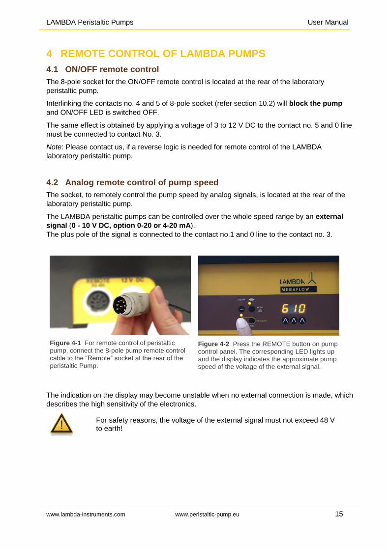
Figure 4-1 For remote control of peristaltic pump, connect the 8-pole pump remote control cable to the “Remote” socket at the rear of the peristaltic Pump.
Figure 4-2 Press the REMOTE button on pump control panel. The corresponding LED lights up and the display indicates the approximate pump speed of the voltage of the external signal.
The indication on the display may become unstable when no external connection is made, which
describes the high sensitivity of the electronics.
For safety reasons, the voltage of the external signal must not exceed 48 V to earth!
LAMBDA Peristaltic Pumps User Manual
www.lambda-instruments.com www.peristaltic-pump.eu 16
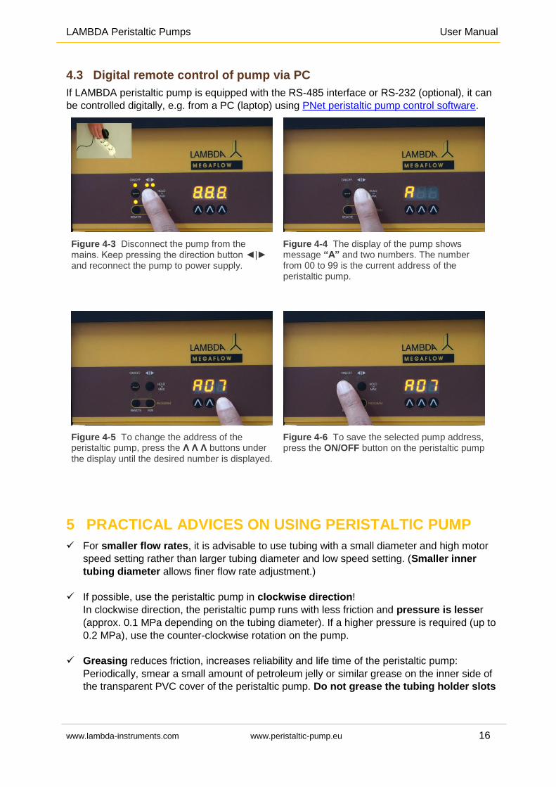
4.3 Digital remote control of pump via PC
If LAMBDA peristaltic pump is equipped with the RS-485 interface or RS-232 (optional), it can
be controlled digitally, e.g. from a PC (laptop) using PNet peristaltic pump control software.
Figure 4-3 Disconnect the pump from the mains. Keep pressing the direction button ◄|► and reconnect the pump to power supply.
Figure 4-4 The display of the pump shows message “A” and two numbers. The number from 00 to 99 is the current address of the peristaltic pump.
Figure 4-5 To change the address of the peristaltic pump, press the Λ Λ Λ buttons under
the display until the desired number is displayed.
Figure 4-6 To save the selected pump address, press the ON/OFF button on the peristaltic pump
5 PRACTICAL ADVICES ON USING PERISTALTIC PUMP
For smaller flow rates, it is advisable to use tubing with a small diameter and high motor
speed setting rather than larger tubing diameter and low speed setting. (Smaller inner
tubing diameter allows finer flow rate adjustment.)
If possible, use the peristaltic pump in clockwise direction!
In clockwise direction, the peristaltic pump runs with less friction and pressure is lesser
(approx. 0.1 MPa depending on the tubing diameter). If a higher pressure is required (up to
0.2 MPa), use the counter-clockwise rotation on the pump.
Greasing reduces friction, increases reliability and life time of the peristaltic pump:
Periodically, smear a small amount of petroleum jelly or similar grease on the inner side of
the transparent PVC cover of the peristaltic pump. Do not grease the tubing holder slots
LAMBDA Peristaltic Pumps User Manual
www.lambda-instruments.com www.peristaltic-pump.eu 17
on the pump head!
If any liquid enters the pump head, disconnect the pump from mains, drain the liquid and
rinse the pump head with water.
For cleaning, you can also remove the entire rotor with rollers: Unscrew the nut (M4 for
PRECIFLOW, MULTIFLOW, HiFLOW and MAXIFLOW; M5 for MEGAFLOW peristaltic
pumps) on the axle of the rotor and pull the rotor out by hand or with a pair of pliers.
After cleaning, grease the axle and replace the rotor by pressing and rotating until the rotor
engages on the motor axis.
Clean the peristaltic pump with a damp cloth. Mild solvents such as ethanol, isopropanol, or
alkanes may also be used, if you the exposure time is short.
Do you have any questions about the operation or cleaning of LAMBDA peristaltic pumps? You
can always ask us for advice using the hotline number or [email protected].
6 FOR YOUR SAFETY IN HANDLING PUMPS
Thanks to the use of a plug-in power supply giving only a low voltage of 12 V DC, the danger of
electrical shock during the use of the LAMBDA peristaltic pump has been virtually eliminated.
This applies even when an electro conductive solution penetrates the peristaltic tubing pump (as
a consequence of an accident).
If this happens, unplug the peristaltic pump from the mains before cleaning and servicing!
Usually, the peristaltic pumps are used in the vertical position. LAMBDA laboratory peristaltic
pumps can also be easily stacked, thus allowing optimal use of the precious laboratory bench
space.
In any case, the ventilation gaps of the peristaltic pump should not be covered!
If the peristaltic tubing pump is not used for an extended period of time, disconnect it from
the mains.
For safety reasons, the voltage of the external signal must not exceed 48 V to earth!
LAMBDA Peristaltic Pumps User Manual
www.lambda-instruments.com www.peristaltic-pump.eu 18
7 CONSTRUCTION ADVANTAGES OF LAMBDA
PERISTALTIC PUMPS
7.1 Construction of the pump head
The asymmetric peristaltic pump head is made of hard, chemically resistant material. The
pressure on the tubing is transmitted gradually through an off-center lever and spring made of
stainless steel. This assures that only minimal pressure is applied to the tubing,
which guarantees:
Reliable functioning of the pump without unnecessary deformation and strain on the
tubing.
If the line is blocked, the liquid pressure is reduced to approx. 1.5 bar (approx. 2 bar, in-
case of MEGAFLOW pump).
Reduced pulsation of the pump liquid.
Construction of the rollers of LAMBDA peristaltic pumps
LAMBDA peristaltic pumps are constructed with ball bearings of a larger diameter with glass
beads. The main advantages of roller construction:
Suppresses corrosion,
Minimizes pulsation and
Reduced friction or lowest mechanical strain on the tubing.
The bearings glide over the tubing so gently, that it is not necessary to prevent the movement
of the tubing by special fixation like stoppers or clamps:
The pump tubing will not be drawn into the peristaltic pump head even at high
pumping speeds and
The lifetime of the pump tubing is considerably extended.
7.2 High quality Swiss motor and microprocessor
The high quality Swiss motor and integrated microprocessor electronics assure:
Highest precision of flow rate
without inertia when switching peristaltic pump ON and OFF.
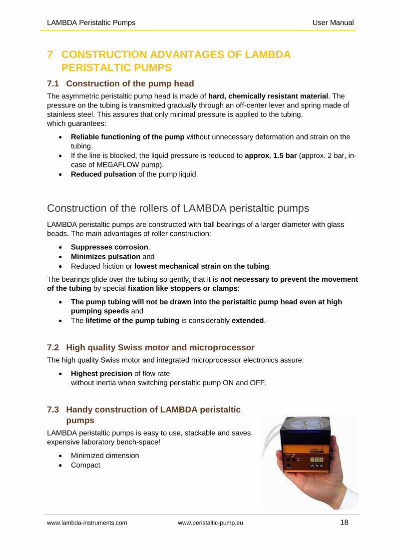
7.3 Handy construction of LAMBDA peristaltic
pumps
LAMBDA peristaltic pumps is easy to use, stackable and saves
expensive laboratory bench-space!
Minimized dimension
Compact
LAMBDA Peristaltic Pumps User Manual
www.lambda-instruments.com www.peristaltic-pump.eu 19
7.4 In-built remote control options
The various remote control options and the possibility of pump flow integration expand the
application possibilities of LAMBDA peristaltic pumps as a peripheral devices in automated
control systems in research laboratories and process optimization:
Acid, base, feed and harvest pumps for lab fermenters and bioreactors or
Chemical synthesis in laboratory
Peristaltic pumps for auto-sampler (lab or field trial)
The LAMBDA peristaltic pumps come with remote socket for analog remote control. In addition,
the peristaltic pumps can be supplied with optional RS-485 or RS-232 interface for digital remote
control, e.g. from a PC (laptop).
(You can find the communication protocol in the Appendix section.)
7.5 Programmable peristaltic pumps
The microprocessors of the MULTIFLOW, MAXIFLOW, HiFLOW and MEGAFLOW peristaltic
pumps allow programming of up to 99 steps of flow and time setting, locally on the pump
display. The flow direction can be selected for each program step.
8 FLOW DIAGRAM OF LAMBDA PERISTALTIC PUMPS
The following pump flow diagrams show the flow rates of LAMBDA peristaltic pumps as a
function of pump speed setting and inner tubing diameter. The flow rates may vary depending
on the fluid being pumped, pressure and pump tubing.
LAMBDA Peristaltic Pumps User Manual
www.lambda-instruments.com www.peristaltic-pump.eu 20
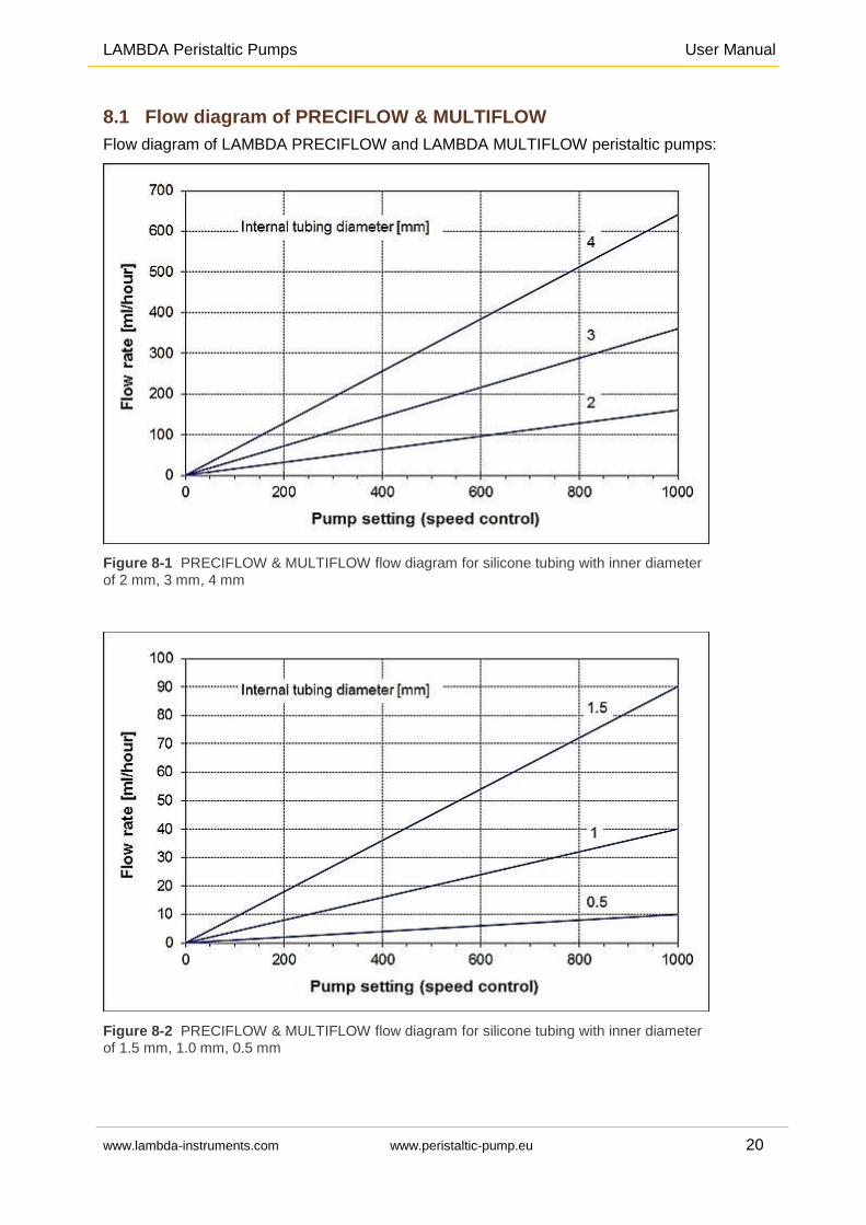
8.1 Flow diagram of PRECIFLOW & MULTIFLOW
Flow diagram of LAMBDA PRECIFLOW and LAMBDA MULTIFLOW peristaltic pumps:
Figure 8-1 PRECIFLOW & MULTIFLOW flow diagram for silicone tubing with inner diameter
of 2 mm, 3 mm, 4 mm
Figure 8-2 PRECIFLOW & MULTIFLOW flow diagram for silicone tubing with inner diameter of 1.5 mm, 1.0 mm, 0.5 mm
LAMBDA Peristaltic Pumps User Manual
www.lambda-instruments.com www.peristaltic-pump.eu 21
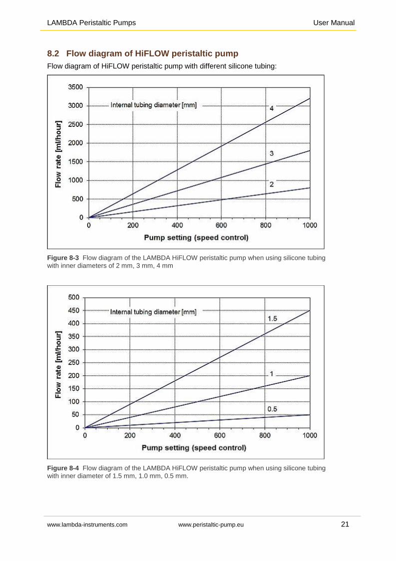
8.2 Flow diagram of HiFLOW peristaltic pump
Flow diagram of HiFLOW peristaltic pump with different silicone tubing:
Figure 8-3 Flow diagram of the LAMBDA HiFLOW peristaltic pump when using silicone tubing
with inner diameters of 2 mm, 3 mm, 4 mm
Figure 8-4 Flow diagram of the LAMBDA HiFLOW peristaltic pump when using silicone tubing with inner diameter of 1.5 mm, 1.0 mm, 0.5 mm.
LAMBDA Peristaltic Pumps User Manual
www.lambda-instruments.com www.peristaltic-pump.eu 22
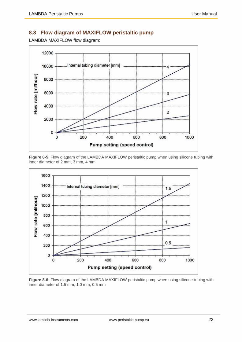
8.3 Flow diagram of MAXIFLOW peristaltic pump
LAMBDA MAXIFLOW flow diagram:
Figure 8-5 Flow diagram of the LAMBDA MAXIFLOW peristaltic pump when using silicone tubing with
inner diameter of 2 mm, 3 mm, 4 mm
Figure 8-6 Flow diagram of the LAMBDA MAXIFLOW peristaltic pump when using silicone tubing with
inner diameter of 1.5 mm, 1.0 mm, 0.5 mm
LAMBDA Peristaltic Pumps User Manual
www.lambda-instruments.com www.peristaltic-pump.eu 23
8.4 Flow rate of MEGAFLOW peristaltic pump
Minimum flow rate of MEGAFLOW peristaltic pump with silicone tubing of 1 mm inner
diameter: 0.2 ml/h
Maximum flow rate of MEGAFLOW peristaltic pump with silicone tubing of 8 mm inner
diameter: 60 L/h
9 APPLICATION OF LAMBDA PERISTALTIC PUMPS
LAMBDA Peristaltic pumps are used, among others, in the following fields of application:
Chromatography: Liquid chromatography,
collecting fractions, sampling, taking samples,
gradient elution, pouring gradient gels, gradient
formation, …
Single use system: LAMBDA peristaltic pumps for
sterile and precise addition/removal of liquid in the
contamination sensitive processes.
Fermentations & cell culture: Addition of nutrients,
pH control by automatic addition of acid/base,
antifoam control by dosing antifoam, C-feed, feed
and harvest pumps for continuous processes like
chemostat.
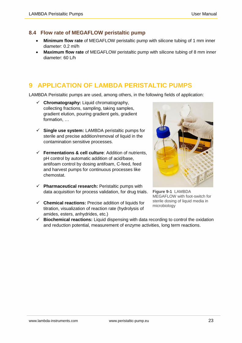
Pharmaceutical research: Peristaltic pumps with
data acquisition for process validation, for drug trials.
Chemical reactions: Precise addition of liquids for
titration, visualization of reaction rate (hydrolysis of
amides, esters, anhydrides, etc.)
Biochemical reactions: Liquid dispensing with data recording to control the oxidation
and reduction potential, measurement of enzyme activities, long term reactions.
Figure 9-1 LAMBDA MEGAFLOW with foot-switch for sterile dosing of liquid media in microbiology
LAMBDA Peristaltic Pumps User Manual
www.lambda-instruments.com www.peristaltic-pump.eu 24
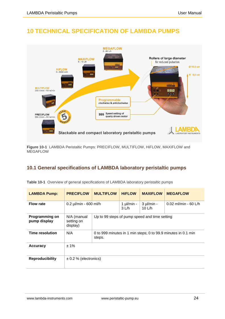
10 TECHNICAL SPECIFICATION OF LAMBDA PUMPS
Figure 10-1 LAMBDA Peristaltic Pumps: PRECIFLOW, MULTIFLOW, HiFLOW, MAXIFLOW and
MEGAFLOW
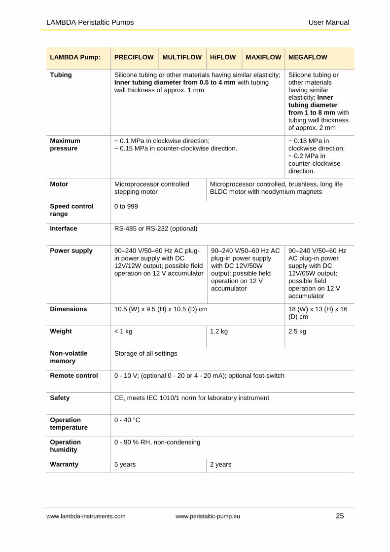
10.1 General specifications of LAMBDA laboratory peristaltic pumps
Table 10-1 Overview of general specifications of LAMBDA laboratory peristaltic pumps
LAMBDA Pump: PRECIFLOW MULTIFLOW HiFLOW MAXIFLOW MEGAFLOW
Flow rate 0.2 µl/min - 600 ml/h 1 µl/min - 3 L/h
3 µl/min - 10 L/h
0.02 ml/min - 60 L/h
Programming on pump display
N/A (manual setting on display)
Up to 99 steps of pump speed and time setting
Time resolution N/A 0 to 999 minutes in 1 min steps; 0 to 99.9 minutes in 0.1 min steps.
Accuracy ± 1%
Reproducibility ± 0.2 % (electronics)
LAMBDA Peristaltic Pumps User Manual
www.lambda-instruments.com www.peristaltic-pump.eu 25
LAMBDA Pump: PRECIFLOW MULTIFLOW HiFLOW MAXIFLOW MEGAFLOW
Tubing Silicone tubing or other materials having similar elasticity; Inner tubing diameter from 0.5 to 4 mm with tubing wall thickness of approx. 1 mm
Silicone tubing or other materials having similar elasticity; Inner tubing diameter from 1 to 8 mm with tubing wall thickness of approx. 2 mm
Maximum pressure
~ 0.1 MPa in clockwise direction; ~ 0.15 MPa in counter-clockwise direction.
~ 0.18 MPa in clockwise direction; ~ 0.2 MPa in counter-clockwise direction.
Motor Microprocessor controlled stepping motor
Microprocessor controlled, brushless, long life BLDC motor with neodymium magnets
Speed control range
0 to 999
Interface RS-485 or RS-232 (optional)
Power supply 90–240 V/50–60 Hz AC plug-in power supply with DC 12V/12W output; possible field operation on 12 V accumulator
90–240 V/50–60 Hz AC plug-in power supply with DC 12V/50W output; possible field operation on 12 V accumulator
90–240 V/50–60 Hz AC plug-in power supply with DC 12V/65W output; possible field operation on 12 V accumulator
Dimensions 10.5 (W) x 9.5 (H) x 10.5 (D) cm 18 (W) x 13 (H) x 16 (D) cm
Weight < 1 kg 1.2 kg 2.5 kg
Non-volatile memory
Storage of all settings
Remote control 0 - 10 V; (optional 0 - 20 or 4 - 20 mA); optional foot-switch
Safety CE, meets IEC 1010/1 norm for laboratory instrument
Operation temperature
0 - 40 °C
Operation humidity
0 - 90 % RH, non-condensing
Warranty 5 years 2 years
LAMBDA Peristaltic Pumps User Manual
www.lambda-instruments.com www.peristaltic-pump.eu 26
For safety reasons, the voltage of the external signal must not exceed 48 V to earth!
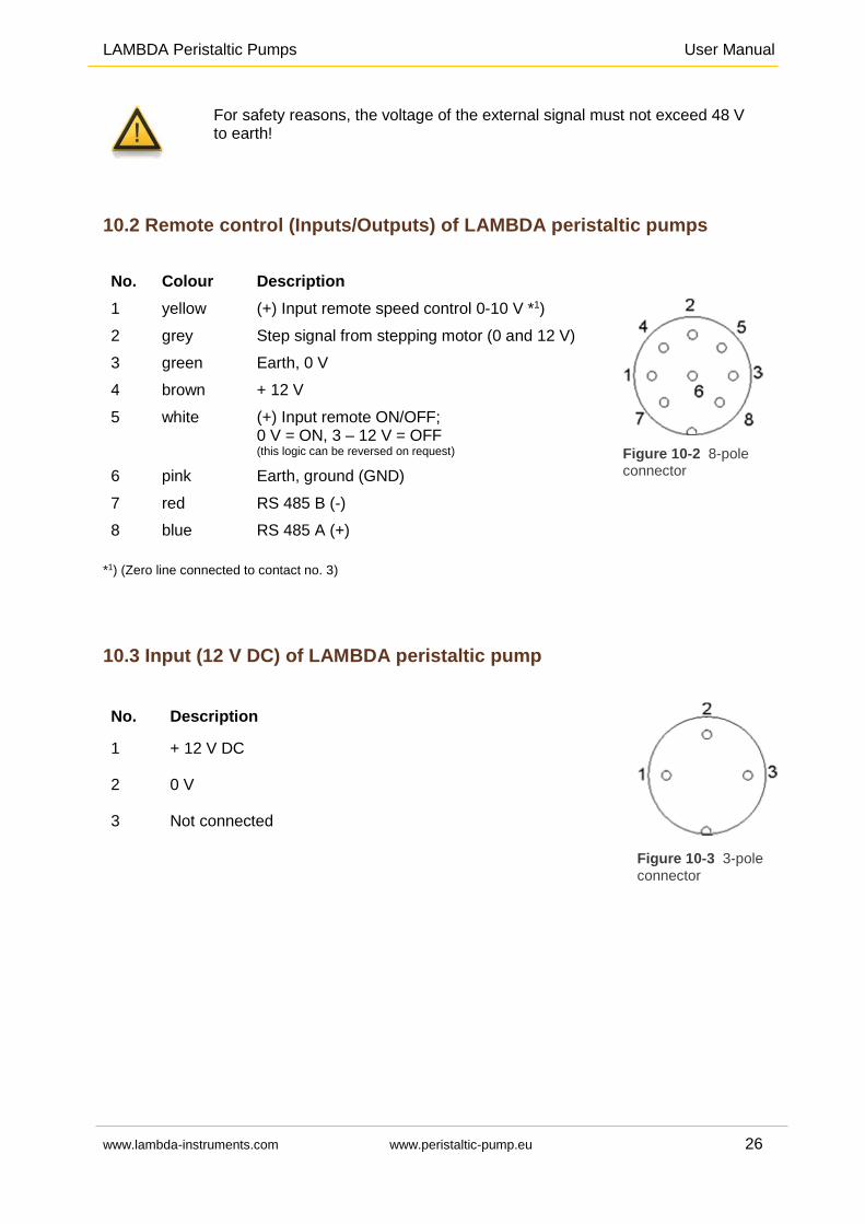
10.2 Remote control (Inputs/Outputs) of LAMBDA peristaltic pumps
No. Colour Description
1 yellow (+) Input remote speed control 0-10 V *1)
Figure 10-2 8-pole connector
2 grey Step signal from stepping motor (0 and 12 V)
3 green Earth, 0 V
4 brown + 12 V
5 white (+) Input remote ON/OFF; 0 V = ON, 3 – 12 V = OFF (this logic can be reversed on request)
6 pink Earth, ground (GND)
7 red RS 485 B (-)
8 blue RS 485 A (+)
*1) (Zero line connected to contact no. 3)
10.3 Input (12 V DC) of LAMBDA peristaltic pump
No. Description
Figure 10-3 3-pole
connector
1 + 12 V DC
2 0 V
3 Not connected
LAMBDA Peristaltic Pumps User Manual
www.lambda-instruments.com www.peristaltic-pump.eu 27
11 ACCESSORIES AND SPARE PARTS FOR LAMBDA PUMPS
For accessories and spare parts of LAMBDA peristaltic pumps (PRECIFLOW, MULTIFLOW,
HiFLOW, MAXIFLOW and MEGAFLOW), please visit www.lambda-instruments.com or contact
us via email at [email protected].
11.1 LAMBDA INTEGRATOR for Pumps (Art. No. 4803)
LAMBDA pumps and dispenser are the only pumps on the market, which allow a simple and
precise integration of the amount of liquid, solid or gas that has been delivered by the
pump: for the flow integration, the LAMBDA PUMP-FLOW INTEGRATOR (Art. No. 4803) is
activated.
You can find the detailed information about LAMBDA pump-flow INTEGRATOR at www.lambda-
instruments.com/pump-flow-integrator/.
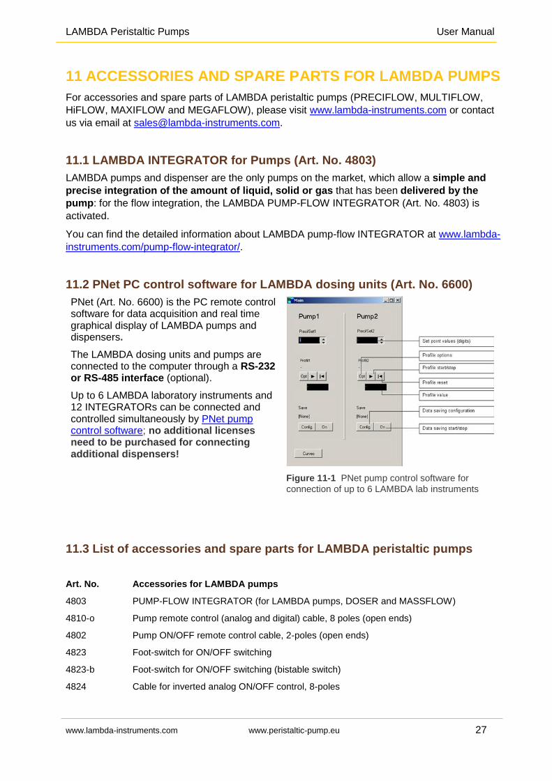
11.2 PNet PC control software for LAMBDA dosing units (Art. No. 6600)
PNet (Art. No. 6600) is the PC remote control software for data acquisition and real time graphical display of LAMBDA pumps and dispensers.
The LAMBDA dosing units and pumps are connected to the computer through a RS-232 or RS-485 interface (optional).
Up to 6 LAMBDA laboratory instruments and 12 INTEGRATORs can be connected and controlled simultaneously by PNet pump control software; no additional licenses need to be purchased for connecting additional dispensers!
Figure 11-1 PNet pump control software for
connection of up to 6 LAMBDA lab instruments
11.3 List of accessories and spare parts for LAMBDA peristaltic pumps
Art. No. Accessories for LAMBDA pumps
4803 PUMP-FLOW INTEGRATOR (for LAMBDA pumps, DOSER and MASSFLOW)
4810-o Pump remote control (analog and digital) cable, 8 poles (open ends)
4802 Pump ON/OFF remote control cable, 2-poles (open ends)
4823 Foot-switch for ON/OFF switching
4823-b Foot-switch for ON/OFF switching (bistable switch)
4824 Cable for inverted analog ON/OFF control, 8-poles
LAMBDA Peristaltic Pumps User Manual
www.lambda-instruments.com www.peristaltic-pump.eu 28
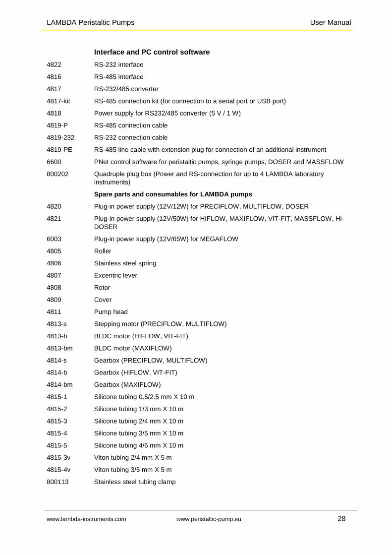
Interface and PC control software
4822 RS-232 interface
4816 RS-485 interface
4817 RS-232/485 converter
4817-kit RS-485 connection kit (for connection to a serial port or USB port)
4818 Power supply for RS232/485 converter (5 V / 1 W)
4819-P RS-485 connection cable
4819-232 RS-232 connection cable
4819-PE RS-485 line cable with extension plug for connection of an additional instrument
6600 PNet control software for peristaltic pumps, syringe pumps, DOSER and MASSFLOW
800202 Quadruple plug box (Power and RS-connection for up to 4 LAMBDA laboratory
instruments)
Spare parts and consumables for LAMBDA pumps
4820 Plug-in power supply (12V/12W) for PRECIFLOW, MULTIFLOW, DOSER
4821 Plug-in power supply (12V/50W) for HIFLOW, MAXIFLOW, VIT-FIT, MASSFLOW, Hi-
DOSER
6003 Plug-in power supply (12V/65W) for MEGAFLOW
4805 Roller
4806 Stainless steel spring
4807 Excentric lever
4808 Rotor
4809 Cover
4811 Pump head
4813-s Stepping motor (PRECIFLOW, MULTIFLOW)
4813-b BLDC motor (HIFLOW, VIT-FIT)
4813-bm BLDC motor (MAXIFLOW)
4814-s Gearbox (PRECIFLOW, MULTIFLOW)
4814-b Gearbox (HIFLOW, VIT-FIT)
4814-bm Gearbox (MAXIFLOW)
4815-1 Silicone tubing 0.5/2.5 mm X 10 m
4815-2 Silicone tubing 1/3 mm X 10 m
4815-3 Silicone tubing 2/4 mm X 10 m
4815-4 Silicone tubing 3/5 mm X 10 m
4815-5 Silicone tubing 4/6 mm X 10 m
4815-3v Viton tubing 2/4 mm X 5 m
4815-4v Viton tubing 3/5 mm X 5 m
800113 Stainless steel tubing clamp
LAMBDA Peristaltic Pumps User Manual
www.lambda-instruments.com www.peristaltic-pump.eu 29
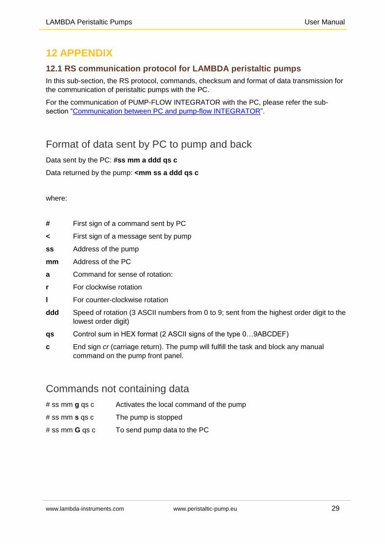
12 APPENDIX
12.1 RS communication protocol for LAMBDA peristaltic pumps
In this sub-section, the RS protocol, commands, checksum and format of data transmission for
the communication of peristaltic pumps with the PC.
For the communication of PUMP-FLOW INTEGRATOR with the PC, please refer the sub-
section “Communication between PC and pump-flow INTEGRATOR”.
Format of data sent by PC to pump and back
Data sent by the PC: #ss mm a ddd qs c
Data returned by the pump: <mm ss a ddd qs c
where:
# First sign of a command sent by PC
< First sign of a message sent by pump
ss Address of the pump
mm Address of the PC
a Command for sense of rotation:
r For clockwise rotation
l For counter-clockwise rotation
ddd Speed of rotation (3 ASCII numbers from 0 to 9; sent from the highest order digit to the
lowest order digit)
qs Control sum in HEX format (2 ASCII signs of the type 0…9ABCDEF)
c End sign cr (carriage return). The pump will fulfill the task and block any manual
command on the pump front panel.
Commands not containing data
# ss mm g qs c Activates the local command of the pump
# ss mm s qs c The pump is stopped
# ss mm G qs c To send pump data to the PC
LAMBDA Peristaltic Pumps User Manual
www.lambda-instruments.com www.peristaltic-pump.eu 30
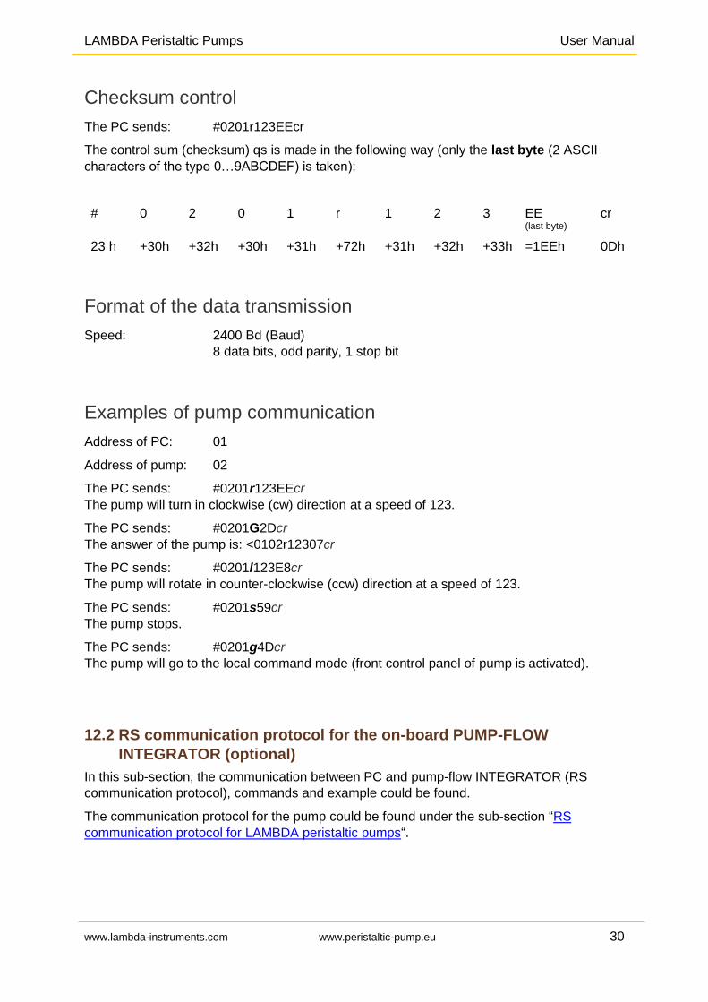
Checksum control
The PC sends: #0201r123EEcr
The control sum (checksum) qs is made in the following way (only the last byte (2 ASCII
characters of the type 0…9ABCDEF) is taken):
# 0 2 0 1 r 1 2 3 EE (last byte)
cr
23 h +30h +32h +30h +31h +72h +31h +32h +33h =1EEh 0Dh
Format of the data transmission
Speed: 2400 Bd (Baud)
8 data bits, odd parity, 1 stop bit
Examples of pump communication
Address of PC: 01
Address of pump: 02
The PC sends: #0201r123EEcr
The pump will turn in clockwise (cw) direction at a speed of 123.
The PC sends: #0201G2Dcr
The answer of the pump is: <0102r12307cr
The PC sends: #0201l123E8cr
The pump will rotate in counter-clockwise (ccw) direction at a speed of 123.
The PC sends: #0201s59cr
The pump stops.
The PC sends: #0201g4Dcr
The pump will go to the local command mode (front control panel of pump is activated).
12.2 RS communication protocol for the on-board PUMP-FLOW
INTEGRATOR (optional)
In this sub-section, the communication between PC and pump-flow INTEGRATOR (RS
communication protocol), commands and example could be found.
The communication protocol for the pump could be found under the sub-section “RS
communication protocol for LAMBDA peristaltic pumps“.
LAMBDA Peristaltic Pumps User Manual
www.lambda-instruments.com www.peristaltic-pump.eu 31
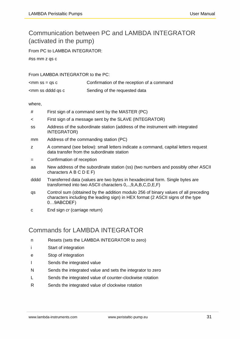
Communication between PC and LAMBDA INTEGRATOR
(activated in the pump)
From PC to LAMBDA INTEGRATOR:
#ss mm z qs c
From LAMBDA INTEGRATOR to the PC:
<mm ss = qs c Confirmation of the reception of a command
<mm ss dddd qs c Sending of the requested data
where,
# First sign of a command sent by the MASTER (PC)
< First sign of a message sent by the SLAVE (INTEGRATOR)
ss Address of the subordinate station (address of the instrument with integrated INTEGRATOR)
mm Address of the commanding station (PC)
z A command (see below): small letters indicate a command, capital letters request data transfer from the subordinate station
= Confirmation of reception
aa New address of the subordinate station (ss) (two numbers and possibly other ASCII characters A B C D E F)
dddd Transferred data (values are two bytes in hexadecimal form. Single bytes are transformed into two ASCII characters 0,..,9,A,B,C,D,E,F)
qs Control sum (obtained by the addition modulo 256 of binary values of all preceding characters including the leading sign) in HEX format (2 ASCII signs of the type 0…9ABCDEF)
c End sign cr (carriage return)
Commands for LAMBDA INTEGRATOR
n Resets (sets the LAMBDA INTEGRATOR to zero)
i Start of integration
e Stop of integration
I Sends the integrated value
N Sends the integrated value and sets the integrator to zero
L Sends the integrated value of counter-clockwise rotation
R Sends the integrated value of clockwise rotation
LAMBDA Peristaltic Pumps User Manual
www.lambda-instruments.com www.peristaltic-pump.eu 32
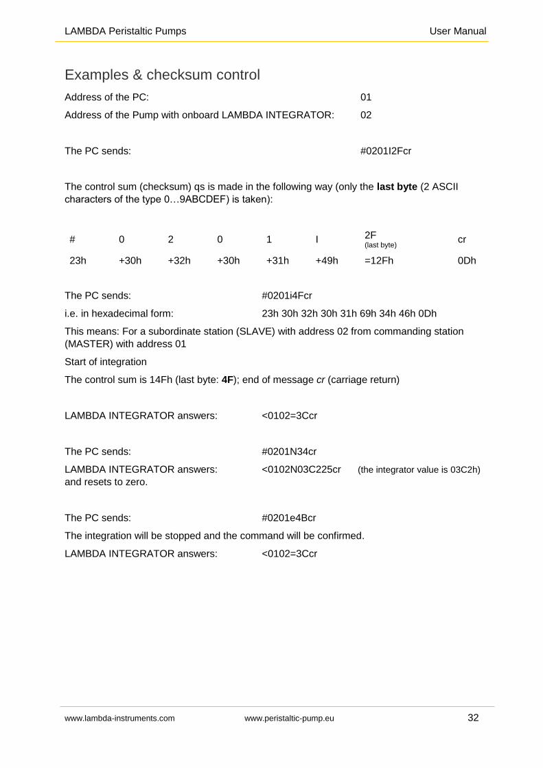
Examples & checksum control
Address of the PC: 01
Address of the Pump with onboard LAMBDA INTEGRATOR: 02
The PC sends: #0201I2Fcr
The control sum (checksum) qs is made in the following way (only the last byte (2 ASCII
characters of the type 0…9ABCDEF) is taken):
# 0 2 0 1 I 2F (last byte) cr
23h +30h +32h +30h +31h +49h =12Fh 0Dh
The PC sends: #0201i4Fcr
i.e. in hexadecimal form: 23h 30h 32h 30h 31h 69h 34h 46h 0Dh
This means: For a subordinate station (SLAVE) with address 02 from commanding station
(MASTER) with address 01
Start of integration
The control sum is 14Fh (last byte: 4F); end of message cr (carriage return)
LAMBDA INTEGRATOR answers: <0102=3Ccr
The PC sends: #0201N34cr
LAMBDA INTEGRATOR answers: <0102N03C225cr (the integrator value is 03C2h)
and resets to zero.
The PC sends: #0201e4Bcr
The integration will be stopped and the command will be confirmed.
LAMBDA INTEGRATOR answers: <0102=3Ccr
LAMBDA Peristaltic Pumps User Manual
www.lambda-instruments.com www.peristaltic-pump.eu 33
13 GUARANTEE ON LABORATORY PUMPS
LAMBDA Laboratory Instruments offer a 5 year warranty on LAMBDA PRECIFLOW and
LAMBDA MULTIFLOW lab pumps for all labor and components when the instrument has been
used according to our operating instructions and the advice given.
LAMBDA provides a 2 year guarantee on material and manufacturing defects of HiFLOW,
MAXIFLOW and MEGAFLOW peristaltic pumps, if the instrument was used according to the
user manual and advices given.
Conditions of guarantee
The instrument must be returned with a complete description of the defect or problem, after consultation with LAMBDA at [email protected].
The customer will send the instrument to LAMBDA service office.
Damage or loss of items during transport will not be compensated by LAMBDA.
Failure to fulfil these requirements will disqualify the customer from compensation.
Serial number: _____________________________
Guarantee from: _____________________________
LAMBDA Laboratory Instruments Sihlbruggstrasse 105 CH-6340 Baar SWITZERLAND – EUROPE Tel.: +41 444 50 20 71 Fax: +41 444 50 20 72
LAMBDA CZ s.r.o. Lozibky 1 CZ-61400 Brno CZECH REPUBLIC - EU Hotline: +420 603 970 653
www.lambda-instruments.com Email: [email protected]
www.peristaltic-pump.eu www.peristalticpump.info