LabVIEWTM Intermediate I Successful Development Practices ...
452
LabVIEW TM Intermediate I Successful Development Practices Course Manual Course Software Version 8.0 October 2005 Edition Part Number 323756B-01 LabVIEW Intermediate I Course Manual Copyright © 2004–2005 National Instruments Corporation. All rights reserved. Under the copyright laws, this publication may not be reproduced or transmitted in any form, electronic or mechanical, including photocopying, recording, storing in an information retrieval system, or translating, in whole or in part, without the prior written consent of National Instruments Corporation. In regards to components used in USI (Xerces C++, ICU, and HDF5), the following copyrights apply. For a listing of the conditions and disclaimers, refer to the USICopyrights.chm. This product includes software developed by the Apache Software Foundation (http:/www.apache.org/). Copyright © 1999 The Apache Software Foundation. All rights reserved. Copyright © 1995–2003 International Business Machines Corporation and others. All rights reserved. NCSA HDF5 (Hierarchical Data Format 5) Software Library and Utilities Copyright 1998, 1999, 2000, 2001, 2003 by the Board of Trustees of the University of Illinois. All rights reserved. Trademarks National Instruments, NI, ni.com, and LabVIEW are trademarks of National Instruments Corporation. Refer to the Terms of Use section on ni.com/legal for more information about National Instruments trademarks. Other product and company names mentioned herein are trademarks or trade names of their respective companies. Members of the National Instruments Alliance Partner Program are business entities independent from National Instruments and have no agency, partnership, or joint-venture relationship with National Instruments. Patents For patents covering National Instruments products, refer to the appropriate location: Help»Patents in your software, the patents.txt file on your CD, or ni.com/legal/patents.
Transcript of LabVIEWTM Intermediate I Successful Development Practices ...
LabVIEWTM Intermediate I Successful Development Practices Course Manual
Course Software Version 8.0October 2005 EditionPart Number 323756B-01
LabVIEW Intermediate I Course Manual
Copyright
© 2004–2005 National Instruments Corporation. All rights reserved. Under the copyright laws, this publication may not be reproduced or transmitted in any form, electronic or mechanical, including photocopying, recording, storing in an information retrieval system, or translating, in whole or in part, without the prior written consent of National Instruments Corporation.
In regards to components used in USI (Xerces C++, ICU, and HDF5), the following copyrights apply. For a listing of the conditions and disclaimers, refer to the USICopyrights.chm.
This product includes software developed by the Apache Software Foundation (http:/www.apache.org/). Copyright
© 1999 The Apache Software Foundation. All rights reserved.
Copyright © 1995–2003 International Business Machines Corporation and others. All rights reserved.
NCSA HDF5 (Hierarchical Data Format 5) Software Library and UtilitiesCopyright 1998, 1999, 2000, 2001, 2003 by the Board of Trustees of the University of Illinois. All rights reserved.
TrademarksNational Instruments, NI, ni.com, and LabVIEW are trademarks of National Instruments Corporation. Refer to the Terms of Use section on ni.com/legal for more information about National Instruments trademarks.
Other product and company names mentioned herein are trademarks or trade names of their respective companies.
Members of the National Instruments Alliance Partner Program are business entities independent from National Instruments and have no agency, partnership, or joint-venture relationship with National Instruments.
PatentsFor patents covering National Instruments products, refer to the appropriate location: Help»Patents in your software, the patents.txt file on your CD, or ni.com/legal/patents.

Worldwide Technical Support and Product Informationni.com
National Instruments Corporate Headquarters11500 North Mopac Expressway Austin, Texas 78759-3504 USA Tel: 512 683 0100
Worldwide Offices
Australia 1800 300 800, Austria 43 0 662 45 79 90 0, Belgium 32 0 2 757 00 20, Brazil 55 11 3262 3599, Canada 800 433 3488, China 86 21 6555 7838, Czech Republic 420 224 235 774, Denmark 45 45 76 26 00, Finland 385 0 9 725 725 11, France 33 0 1 48 14 24 24, Germany 49 0 89 741 31 30, India 91 80 51190000, Israel 972 0 3 6393737, Italy 39 02 413091, Japan 81 3 5472 2970, Korea 82 02 3451 3400, Lebanon 961 0 1 33 28 28, Malaysia 1800 887710, Mexico 01 800 010 0793, Netherlands 31 0 348 433 466, New Zealand 0800 553 322, Norway 47 0 66 90 76 60, Poland 48 22 3390150, Portugal 351 210 311 210, Russia 7 095 783 68 51, Singapore 1800 226 5886, Slovenia 386 3 425 4200, South Africa 27 0 11 805 8197, Spain 34 91 640 0085, Sweden 46 0 8 587 895 00, Switzerland 41 56 200 51 51, Taiwan 886 02 2377 2222, Thailand 662 278 6777, United Kingdom 44 0 1635 523545
For further support information, refer to the Additional Information and Resources appendix. To comment on National Instruments documentation, refer to the National Instruments Web site at ni.com/info and enter the info code feedback.
© National Instruments Corporation iii LabVIEW Intermediate I Course Manual
Contents
Student GuideA. NI Certification .....................................................................................................viiB. Course Description ...............................................................................................viiiC. What You Need to Get Started .............................................................................viiiD. Installing the Course Software..............................................................................ixE. Course Goals.........................................................................................................ixF. Course Conventions ..............................................................................................x
Lesson 1Successful Development Practices
A. Scalable, Readable, and Maintainable VIs ...........................................................1-2B. Successful Development Practices .......................................................................1-4C. Course Project Overview ......................................................................................1-11Summary.....................................................................................................................1-12
Lesson 2Analyzing the Project
A. Evaluating the Needs of the Customer .................................................................2-2Exercise 2-1 Analyze the Specifications ...............................................................2-5B. Communicating with the Customer ......................................................................2-6C. Developing the Requirements Document .............................................................2-8Exercise 2-2 Analyze a Requirements Document .................................................2-9D. Defining the Application ......................................................................................2-16Summary.....................................................................................................................2-29
Lesson 3Designing the User Interface
A. User Interface Design Issues.................................................................................3-2B. User Interface Layout Issues.................................................................................3-4C. Front Panel Prototyping ........................................................................................3-16D. User Interface Example ........................................................................................3-17E. Localizing User Interfaces ....................................................................................3-18Exercise 3-1 Concept: User-Interface Design Techniques....................................3-20Summary.....................................................................................................................3-26
Contents
LabVIEW Intermediate I Course Manual iv ni.com
Lesson 4Designing the Project
A. Design Patterns .....................................................................................................4-2Exercise 4-1 Concept: Experiment with Design Patterns......................................4-12B. Event-Based Design Patterns................................................................................4-13Exercise 4-2 Concept: Experiment with Event Structures ....................................4-22Exercise 4-3 Concept: Experiment with Event-Based Design Patterns ................4-28C. Advanced Event-Based Design Patterns...............................................................4-29Exercise 4-4 Concept: User Event Techniques .....................................................4-32Exercise 4-5 Choose a Scalable Architecture........................................................4-40D. Creating a Hierarchical Architecture ....................................................................4-41E. Using the LabVIEW Project and Project Libraries ..............................................4-42Exercise 4-6 Using the LabVIEW Project.............................................................4-54F. Choosing Data Types............................................................................................4-55Exercise 4-7 Choose Data Types...........................................................................4-57G. Information Hiding ...............................................................................................4-60Exercise 4-8 Information Hiding...........................................................................4-64H. Designing Error Handling Strategies ....................................................................4-76Exercise 4-9 Design Error Handling Strategy .......................................................4-80Summary.....................................................................................................................4-84
Lesson 5Implementing the User Interface
A. Implementing User Interface-Based Data Types..................................................5-2Exercise 5-1 Implement User Interface-Based Data Types...................................5-8B. Implementing Meaningful Icons...........................................................................5-12Exercise 5-2 Implement a Meaningful Icon ..........................................................5-14C. Implementing Appropriate Connector Panes........................................................5-15Exercise 5-3 Implement an Appropriate Connector Pane .....................................5-18Summary.....................................................................................................................5-19
Lesson 6Implementing Code
A. Configuration Management ..................................................................................6-2B. Implementing a Design Pattern.............................................................................6-7Exercise 6-1 Implement the Design Pattern ..........................................................6-12C. Implementing Code...............................................................................................6-27Exercise 6-2 Timing ..............................................................................................6-49D. Develop Scalable and Maintainable Modules ......................................................6-60Exercise 6-3 Implement Code ...............................................................................6-67E. Implement an Error Handling Strategy.................................................................6-76Exercise 6-4 Implement Error Handling Strategy .................................................6-77Summary.....................................................................................................................6-81
Contents
© National Instruments Corporation v LabVIEW Intermediate I Course Manual
Lesson 7Implementing a Test Plan
A. Verifying the Code................................................................................................7-2B. Implementing a Test Plan for Individual VIs .......................................................7-2C. Implementing a Test Plan for Integrating VIs ......................................................7-6Exercise 7-1 Integrate Initialize and Shutdown Functions....................................7-10Exercise 7-2 Integrate Display Module .................................................................7-16Exercise 7-3 Integrate Record Function ................................................................7-22Exercise 7-4 Integrate Play Function.....................................................................7-28Exercise 7-5 Integrate Stop Function ....................................................................7-33Exercise 7-6 Integrate Error Module .....................................................................7-35Exercise 7-7 Integrate Save and Load Functions ..................................................7-39Exercise 7-8 Integrate Select Cue Function ..........................................................7-46Exercise 7-9 Integrate Move Cue Functions .........................................................7-48Exercise 7-10 Integrate Delete Function .................................................................7-51D. Implementing a Test Plan for the System.............................................................7-53Exercise 7-11 Stress and Load Testing....................................................................7-59Summary.....................................................................................................................7-61
Lesson 8Evaluating VI Performance
A. Steps to Improving Performance ..........................................................................8-2B. Using VI Metrics to Identify VI Issues.................................................................8-2Exercise 8-1 Identify VI Issues with VI Metrics...................................................8-4C. Further Identifying VI Issues with VI Analyzer (Optional) .................................8-5Exercise 8-2 Identify VI Issues with VI Analyzer (Optional)...............................8-12D. Identifying Performance Problems .......................................................................8-13E. Fixing Performance Problems ..............................................................................8-14Exercise 8-3 Concept: Methods of Updating Indicators .......................................8-22Summary.....................................................................................................................8-24
Lesson 9Implementing Documentation
A. Designing Documentation ....................................................................................9-2B. Developing User Documentation..........................................................................9-2C. Describing VIs, Controls, and Indicators..............................................................9-5Exercise 9-1 Document User Interface..................................................................9-7D. Creating Help Files ...............................................................................................9-9Exercise 9-2 Implement Documentation ...............................................................9-10Summary.....................................................................................................................9-12
Contents
LabVIEW Intermediate I Course Manual vi ni.com
Lesson 10Deploying the Application
A. Implementing Code for Stand-Alone Applications ..............................................10-2Exercise 10-1 Implementing Code for Stand-Alone Applications..........................10-8B. Building a Stand-Alone Application.....................................................................10-13Exercise 10-2 Create a Stand-Alone Application....................................................10-21C. Building an Installer..............................................................................................10-23Exercise 10-3 Create an Installer.............................................................................10-32Summary.....................................................................................................................10-34
Appendix AIEEE Requirements Documents
A. Institute of Electrical and Electronic Engineers (IEEE) Standards ......................A-2B. IEEE Requirements Document .............................................................................A-3
Appendix BAdditional Information and Resources
Glossary
Index
Course Evaluation
© National Instruments Corporation vii LabVIEW Intermediate I Course Manual
Student Guide
Thank you for purchasing the LabVIEW Intermediate I: Successful Development Practices course kit. You can begin developing an application soon after you complete the exercises in this manual. This course manual and the accompanying software are used in the three-day, hands-on LabVIEW Intermediate I: Successful Development Practices course.
You can apply the full purchase of this course kit toward the correspondingcourse registration fee if you register within 90 days of purchasing the kit.Visit ni.com/training for online course schedules, syllabi, trainingcenters, and class registration.
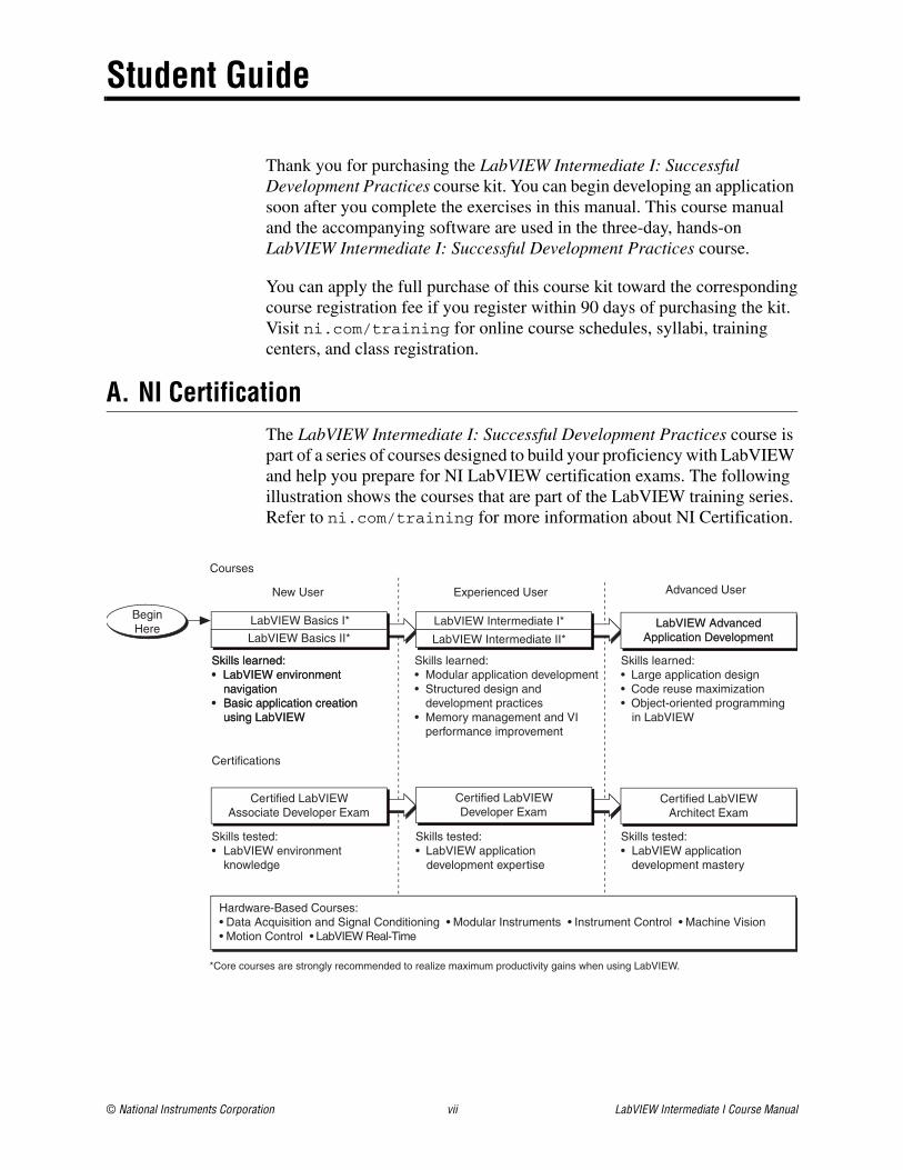
A. NI CertificationThe LabVIEW Intermediate I: Successful Development Practices course is part of a series of courses designed to build your proficiency with LabVIEW and help you prepare for NI LabVIEW certification exams. The following illustration shows the courses that are part of the LabVIEW training series. Refer to ni.com/training for more information about NI Certification.
LabVIEW Intermediate I*
LabVIEW Intermediate II*
New User Experienced User Advanced User
LabVIEW AdvancedApplication Development
LabVIEW AdvancedApplication Development
Certified LabVIEWAssociate Developer Exam
Certified LabVIEWDeveloper Exam
Certified LabVIEWArchitect Exam
Skills tested:• LabVIEW application development expertise
Skills learned:• Modular application development• Structured design and development practices• Memory management and VI performance improvement
Skills learned:• Large application design• Code reuse maximization• Object-oriented programming in LabVIEW
Skills tested:• LabVIEW application development mastery
Skills tested:• LabVIEW environment knowledge
Skills learned:• LabVIEW environment navigation• Basic application creation using LabVIEW
Certifications
Courses
Hardware-Based Courses: • Data Acquisition and Signal Conditioning • Modular Instruments • Instrument Control • Machine Vision • Motion Control • LabVIEW Real-Time
*Core courses are strongly recommended to realize maximum productivity gains when using LabVIEW.
LabVIEW Basics I*
Skills learned:• LabVIEW environment navigation• Basic application creation using LabVIEW
LabVIEW Basics II*
BeginHere
Student Guide
LabVIEW Intermediate I Course Manual viii ni.com
B. Course DescriptionThe LabVIEW Intermediate I: Successful Development Practices course teaches you four fundamental areas of software development in LabVIEW—design, implement, test, and deploy. By the end of the LabVIEW Intermediate I: Successful Development Practices course, you will be able to produce a LabVIEW application that uses good programming practices and is easy to scale, easy to read, and easy to maintain. As a result, you should be able to more effectively develop software with LabVIEW.
This course assumes that you have taken the LabVIEW Basics I: Introduction and LabVIEW Basics II: Development courses or have equivalent experience.
This course kit is designed to be completed in sequence. The course is divided into lessons, each covering a topic or a set of topics. Each lesson consists of:
• An introduction that describes the lesson’s purpose and topics
• A discussion of the topics
• A set of exercises to reinforce the topics presented in the discussion
Note The exercises in this course are cumulative and lead toward developing a final application at the end of the course. If you skip an exercise, use the solution VI for that exercise, available in the C:\Solutions\LabVIEW Intermediate I directory, in later exercises.
• A summary that outlines the important concepts and skills in the lesson
C. What You Need to Get StartedBefore you use this course manual, make sure you have the following items:
❑ Windows 2000 or later installed on your computer; this course is optimized for Windows XP
❑ LabVIEW Professional Development System 8.0 or later
❑ LabVIEW Intermediate I: Successful Development Practices course CD, containing the following folders:
Student Guide
© National Instruments Corporation ix LabVIEW Intermediate I Course Manual
D. Installing the Course SoftwareComplete the following steps to install the course software.
1. Insert the course CD in your computer. The LabVIEW Intermediate Course Material Setup dialog box appears.
2. Click the Next button.
3. Choose Typical setup type and click the Install button to begin the installation.
4. Click the Finish button to exit the Setup Wizard.
5. The installer places the Exercises and Solutions folders at the top level of the C:\ directory.
Exercise files are located in the C:\Exercises\LabVIEW Intermediate I directory.
Repairing or Removing Course MaterialYou can repair or remove the course material using the Add or Remove Programs feature on the Windows Control Panel. Repair the course material to overwrite existing course material with the original, unedited versions of the files. Remove the course material if you no longer need the files on your machine.
E. Course GoalsAfter completing the course, you will be able to:
• Analyze the requirements of an application and choose appropriate design patterns and data structures
• Implement good programming style to create efficient VIs
• Develop techniques to test and validate VIs
• Develop modular applications that are scalable, readable, and maintainable
• Develop techniques to evaluate and improve inherited code
• Use LabVIEW tools to evaluate VI performance
Filename Description
Exercises Folder containing VIs and other files used in the course
Solutions Folder containing completed course exercises

Student Guide
LabVIEW Intermediate I Course Manual x ni.com
• Effectively document VIs
• Use advanced features of the LabVIEW Application Builder to create a stand-alone application
• Use the LabVIEW Application Builder to create a professional installer to use on other platforms
F. Course ConventionsThe following conventions are used in this course manual:
» The » symbol leads you through nested menu items and dialog box options to a final action. The sequence File»Page Setup»Options directs you to pull down the File menu, select the Page Setup item, and select Options from the last dialog box.
This icon denotes a tip, which alerts you to advisory information.
This icon denotes a note, which alerts you to important information.
This icon denotes a caution, which advises you of precautions to take to avoid injury, data loss, or a system crash.
bold Bold text denotes items that you must select or click in the software, such as menu items and dialog box options. Bold text also denotes parameter names, controls and buttons on the front panel, dialog boxes, sections of dialog boxes, menu names, and palette names.
italic Italic text denotes variables, emphasis, a cross reference, or an introduction to a key concept. Italic text also denotes text that is a placeholder for a word or value that you must supply.
monospace Text in this font denotes text or characters that you enter from the keyboard, sections of code, programming examples, and syntax examples. This font also is used for the proper names of disk drives, paths, directories, programs, subprograms, subroutines, device names, functions, operations, variables, filenames, and extensions.
monospace Italic text in this font denotes text that is a placeholder for a word or valueitalic that you must supply.
Platform Text in this font denotes a specific platform and indicates that the text following it applies only to that platform.
© National Instruments Corporation 1-1 LabVIEW Intermediate I Course Manual
1Successful Development Practices
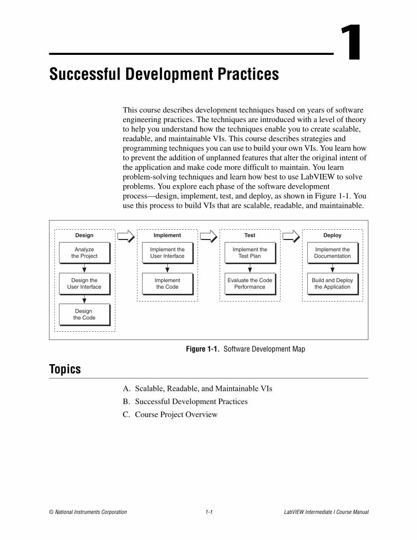
This course describes development techniques based on years of software engineering practices. The techniques are introduced with a level of theory to help you understand how the techniques enable you to create scalable, readable, and maintainable VIs. This course describes strategies and programming techniques you can use to build your own VIs. You learn how to prevent the addition of unplanned features that alter the original intent of the application and make code more difficult to maintain. You learn problem-solving techniques and learn how best to use LabVIEW to solve problems. You explore each phase of the software development process—design, implement, test, and deploy, as shown in Figure 1-1. You use this process to build VIs that are scalable, readable, and maintainable.
Figure 1-1. Software Development Map
TopicsA. Scalable, Readable, and Maintainable VIsB. Successful Development Practices
C. Course Project Overview
Design
Design theUser Interface
Analyzethe Project
Design the Code
Implement
Implement theUser Interface
Implementthe Code
Test
Implement theTest Plan
Evaluate the CodePerformance
Deploy
Implement theDocumentation
Build and Deploythe Application
Lesson 1 Successful Development Practices
LabVIEW Intermediate I Course Manual 1-2 ni.com
A. Scalable, Readable, and Maintainable VIsWhen you use LabVIEW to develop complex applications, you should use good software design principles. You always want to create VIs that are scalable, readable, and maintainable.
• Scalable—Easy to add more functionality to an application without completely redesigning the application.
• Readable—Easy to visually inspect the design of an application and understand its purpose and functionality.
• Maintainable—Easy to change the code by the original developer or any other developer without affecting the intent of the original code.
Because LabVIEW is a programming language, when you program with LabVIEW you encounter many of the same design issues that you encounter when you program in text-based languages. However, LabVIEW provides many powerful features and programming techniques that enable you to focus on producing a solution to a project rather than focusing on syntax or memory issues.
This course shows you powerful programming techniques for developing applications that are scalable, readable, and maintainable.
ScalableIn order to create a scalable VI, you must begin thinking about the design of the application early in the design process. A well-designed scalable VI allows you to easily modify and add additional functionality to the original design. For example, consider a data acquisition VI that acquires data from three thermocouples. Suppose the requirements of the application change, and you need to acquire data from hundreds of thermocouples. If the original VI was designed to be scalable, extending the VI to acquire data from hundreds of thermocouples would be easier than designing a new VI.
Use good design practices to create VIs that are scalable. Many existing applications must be rewritten when changes are needed because the code was not designed to be scalable. For a non-scalable VI, even simple changes, such as acquiring data from more sensors or controlling more relays, can require a rewrite. When you design any application, consider the purpose of the application and how to manage changes when the scale of the application goes beyond the original specification. This course teaches you techniques for designing scalable VIs.
Lesson 1 Successful Development Practices
© National Instruments Corporation 1-3 LabVIEW Intermediate I Course Manual
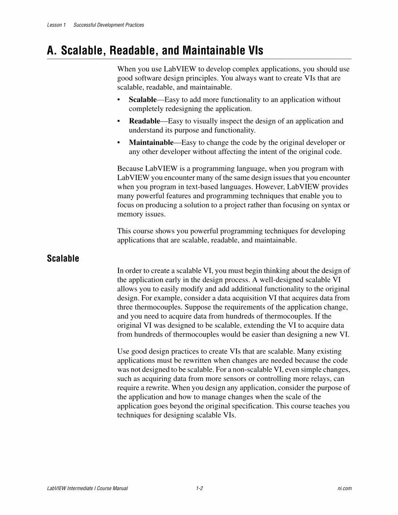
ReadableIn your experience working with LabVIEW, you may have seen block diagrams that were unstructured, difficult to read, and difficult to understand. Confusing and unmaintainable code sometimes is called spaghetti code. Unreadable code can make it impossible to decipher the functionality of a block diagram. Figure 1-2 shows poorly designed block diagram and a well-designed block diagram.
Figure 1-2. Examples of Poorly Designed and Well-Designed Block Diagrams
Code that is difficult to read and difficult to understand is difficult to maintain. This course teaches you techniques to make VIs more readable.
MaintainableA VI written using good program design and architecture allows you to add new features without completely rewriting the application. When you develop an application, keep in mind that another programmer might need to use and modify the VI in the future. By using forethought in designing and creating an application, you can create VIs that are more maintainable.
This course teaches you to apply the features of LabVIEW and use good software design principles that relate directly to LabVIEW to create well-formed, maintainable applications.
1 Poorly Designed 2 Well-Designed
1 2
Lesson 1 Successful Development Practices
LabVIEW Intermediate I Course Manual 1-4 ni.com
B. Successful Development PracticesLabVIEW makes it easy to assemble components of data acquisition, test, and control systems. Because creating applications in LabVIEW is so easy, many people begin to develop VIs immediately with relatively little planning. For simple applications, such as quick lab tests or monitoring applications, this approach can be appropriate. However, for larger development projects, good project planning is vital.
LabVIEW—A Programming LanguageLabVIEW is a multipurpose programming language designed specifically for creating applications in the measurement and automation industry. LabVIEW applications can range from a simple VI with one VI, to extensive applications that contain many VIs organized into a complex hierarchy. As you expand the use of LabVIEW and create more complex applications, the code that comprises the applications becomes more complex.
Many industries around the world use LabVIEW as a tool to perform a wide range of measurement and automation tasks. LabVIEW is used often in environments where safety is critical. For example, a LabVIEW application might measure the size of medical stents that are placed into human arteries. If the programmer fails to correctly design, implement, test, and deploy the application, he could place the patient who receives the stent in a life-threatening position.
Programmers have placed humans in life-threatening positions in the past. In 1987, the United States Food and Drug Administration recalled five Therac-25 medical linear accelerators used in clinical cancer radiotherapy.1 The machines were recalled due to software defects that caused massive radiation overdoses leading to patient death. It was later determined that the Therac-25 overdoses were the result of poor software design to control the safety of the Therac-25. As a programmer, you must create applications that are safe, reliable, easy to maintain, and easy to understand2.
Software LifecyclesSoftware development projects are complex. To deal with these complexities, many developers adhere to a core set of development principles. These principles define the field of software engineering. A major component of this field is the lifecycle model. The lifecycle model describes steps to follow when developing software—from the initial concept stage to the release, maintenance, and subsequent upgrading of the software.
1. United States, United States Government Accounting Office, Medical Device Recalls Examination of Selected Cases GAO/PEMD-90-6 (Washington: GAO, 1989) 40.
2. National Instruments tools are not designed for operating life critical support systems and should not be used in such applications.
Lesson 1 Successful Development Practices
© National Instruments Corporation 1-5 LabVIEW Intermediate I Course Manual
Many different lifecycle models currently exist. Each has advantages and disadvantages in terms of time-to-release, quality, and risk management. This section describes some of the most common models used in software engineering. Many hybrids of these models exist, so you can customize these models to fit the requirements of a project.
Although this section is theoretical in its discussion, in practice consider all the steps these models encompass. Consider how you decide what requirements and specifications the project must meet and how you deal with changes to them. Also consider when you need to meet these requirements and what happens if you do not meet a deadline.
The lifecycle model is a foundation for the entire development process. Good decisions can improve the quality of the software you develop and decrease the time it takes to develop it.
Code and Fix Model The code and fix model probably is the most frequently used development methodology in software engineering. It starts with little or no initial planning. You immediately start developing, fixing problems as they occur, until the project is complete.
Code and fix is a tempting choice when you are faced with a tight development schedule because you begin developing code right away and see immediate results.
Unfortunately, if you find major architectural problems late in the process, you usually have to rewrite large parts of the application. Alternative development models can help you catch these problems in the early concept stages, when making changes is easier and less expensive.
The code and fix model is appropriate only for small projects that are not intended to serve as the basis for future development.
Waterfall Model The waterfall model is the classic model of software engineering. This model is one of the oldest models and is widely used in government projects and in many major companies. Because the model emphasizes planning in the early stages, it catches design flaws before they develop. Also, because the model is document and planning intensive, it works well for projects in which quality control is a major concern.
The pure waterfall lifecycle consists of several non-overlapping stages, as shown in the following figure. The model begins with establishing system requirements and software requirements and continues with architectural
Lesson 1 Successful Development Practices
LabVIEW Intermediate I Course Manual 1-6 ni.com
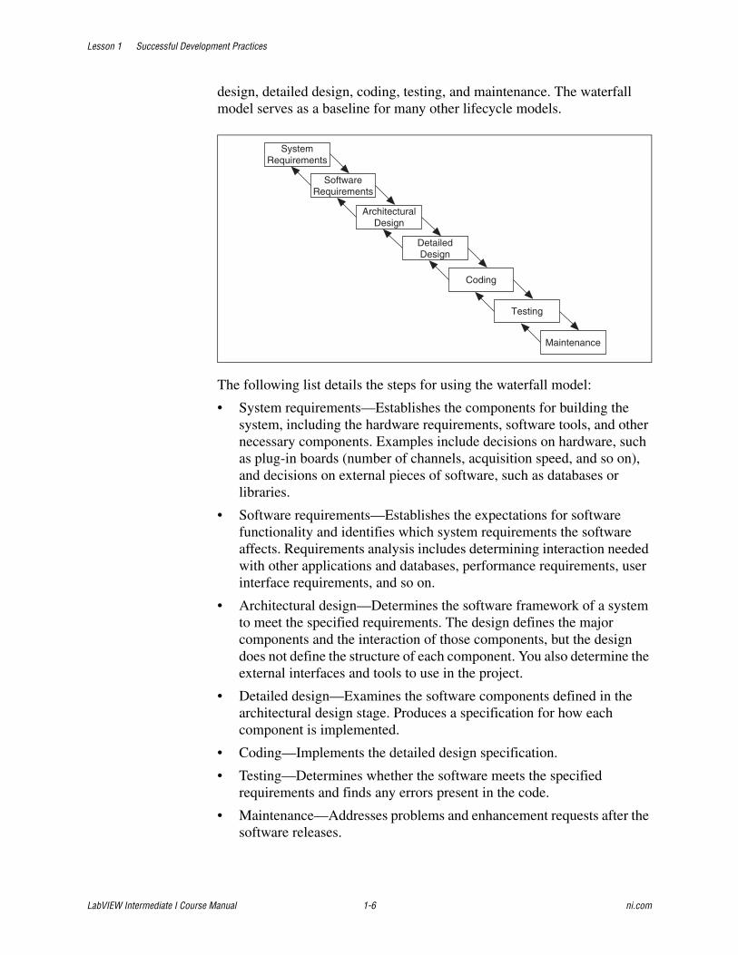
design, detailed design, coding, testing, and maintenance. The waterfall model serves as a baseline for many other lifecycle models.
The following list details the steps for using the waterfall model:
• System requirements—Establishes the components for building the system, including the hardware requirements, software tools, and other necessary components. Examples include decisions on hardware, such as plug-in boards (number of channels, acquisition speed, and so on), and decisions on external pieces of software, such as databases or libraries.
• Software requirements—Establishes the expectations for software functionality and identifies which system requirements the software affects. Requirements analysis includes determining interaction needed with other applications and databases, performance requirements, user interface requirements, and so on.
• Architectural design—Determines the software framework of a system to meet the specified requirements. The design defines the major components and the interaction of those components, but the design does not define the structure of each component. You also determine the external interfaces and tools to use in the project.
• Detailed design—Examines the software components defined in the architectural design stage. Produces a specification for how each component is implemented.
• Coding—Implements the detailed design specification.
• Testing—Determines whether the software meets the specified requirements and finds any errors present in the code.
• Maintenance—Addresses problems and enhancement requests after the software releases.
SystemRequirements
SoftwareRequirements
ArchitecturalDesign
DetailedDesign
Coding
Testing
Maintenance
Lesson 1 Successful Development Practices
© National Instruments Corporation 1-7 LabVIEW Intermediate I Course Manual
In some organizations, a change control board maintains the quality of the product by reviewing each change made in the maintenance stage. Consider applying the full waterfall development cycle model when correcting problems or implementing these enhancement requests.
In each stage, you create documents that explain the objectives and describe the requirements for that phase. At the end of each stage, you hold a review to determine whether the project can proceed to the next stage. You also can incorporate prototyping into any stage from the architectural design and after.
Many people believe you cannot apply this model to all situations. For example, with the pure waterfall model, you must state the requirements before you begin the design, and you must state the complete design before you begin coding. There is no overlap between stages. In real-world development, however, you can discover issues during the design or coding stages that point out errors or gaps in the requirements.
The waterfall method does not prohibit returning to an earlier phase, for example, from the design phase to the requirements phase. However, this involves costly rework. Each completed phase requires formal review and extensive documentation development. Thus, oversights made in the requirements phase are expensive to correct later.
Because the actual development comes late in the process, you do not see results for a long time. This delay can be disconcerting to management and to customers. Many people also think the amount of documentation is excessive and inflexible.
Although the waterfall model has its weaknesses, it is instructive because it emphasizes important stages of project development. Even if you do not apply this model, consider each of these stages and its relationship to your own project.
Modified Waterfall Model Many engineers recommend modified versions of the waterfall lifecycle. These modifications tend to focus on allowing some of the stages to overlap, thus reducing the documentation requirements and the cost of returning to earlier stages to revise them. Another common modification is to incorporate prototyping into the requirements phases.
Overlapping stages, such as the requirements stage and the design stage, make it possible to integrate feedback from the design phase into the requirements. However, overlapping stages can make it difficult to know when you are finished with a given stage. Consequently, progress is more difficult to track. Without distinct stages, problems can cause you to defer
Lesson 1 Successful Development Practices
LabVIEW Intermediate I Course Manual 1-8 ni.com
important decisions until later in the process when they are more expensive to correct.
Prototyping One of the main problems with the waterfall model is that the requirements often are not completely understood in the early development stages. When you reach the design or coding stages, you begin to see how everything works together, and you can discover that you need to adjust the requirements.
Prototyping is an effective tool for demonstrating how a design meets a set of requirements. You can build a prototype, adjust the requirements, and revise the prototype several times until you have a clear picture of the overall objectives. In addition to clarifying the requirements, a prototype also defines many areas of the design simultaneously.
The pure waterfall model allows for prototyping in the later architectural design stage and subsequent stages but not in the early requirements stages.
However, prototyping has its drawbacks. Because it appears that you have a working system, customers may expect a complete system sooner than is possible. In most cases, prototypes are built on compromises that allow it to come together quickly but prevent the prototype from being an effective basis for future development. You need to decide early if you want to use the prototype as a basis for future development. All parties need to agree with this decision before development begins.
Be careful that prototyping does not become a disguise for a code and fix development cycle. Before you begin prototyping, gather clear requirements and create a design plan. Limit the amount of time you spend prototyping before you begin. Time limits help to avoid overdoing the prototyping phase. As you incorporate changes, update the requirements and the current design. After you finish prototyping, consider returning to one of the other development models. For example, consider prototyping as part of the requirements or design phases of the waterfall model.
LabVIEW Prototyping Methods There are a number of ways to prototype a system in LabVIEW. In systems with I/O requirements that are difficult to satisfy, you can develop a prototype to test the control and acquisition loops and rates. In I/O prototypes, random data can simulate data acquired in the real system.
Systems with many user interface requirements are perfect for prototyping. Determining the method you use to display data or prompt the user for settings is difficult on paper. Instead, consider designing VI front panels with the controls and indicators you need. Leave the block diagram empty
Lesson 1 Successful Development Practices
© National Instruments Corporation 1-9 LabVIEW Intermediate I Course Manual
and figure out how the controls work and how various actions require other front panels. For more extensive prototypes, tie the front panels together. However, do not get carried away with this process.
If you are bidding on a project for a client, using front panel prototypes is an extremely effective way to discuss with the client how you can satisfy his or her requirements. Because you can add and remove controls quickly, especially if the block diagrams are empty, you help customers clarify requirements.
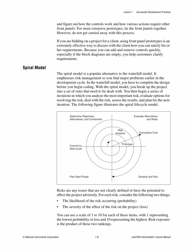
Spiral Model The spiral model is a popular alternative to the waterfall model. It emphasizes risk management so you find major problems earlier in the development cycle. In the waterfall model, you have to complete the design before you begin coding. With the spiral model, you break up the project into a set of risks that need to be dealt with. You then begin a series of iterations in which you analyze the most important risk, evaluate options for resolving the risk, deal with the risk, assess the results, and plan for the next iteration. The following figure illustrates the spiral lifecycle model.
Risks are any issues that are not clearly defined or have the potential to affect the project adversely. For each risk, consider the following two things:
• The likelihood of the risk occurring (probability)
• The severity of the effect of the risk on the project (loss)
You can use a scale of 1 to 10 for each of these items, with 1 representing the lowest probability or loss and 10 representing the highest. Risk exposure is the product of these two rankings.
Cumulative Cost
Evaluate Alternativesand Risks
Determine Objectives,Alternatives, and Constraints
Develop and Test
Prototype
Plan Next Phase
Commit toNext Cycle
RiskAnalysis

Lesson 1 Successful Development Practices
LabVIEW Intermediate I Course Manual 1-10 ni.com
Use something such as the following table to keep track of the top risk items of the project.
In general, deal with the risks with the highest risk exposure first. In this example, the first spiral deals with the potential of the data acquisition rates being too high. If after the first spiral, you demonstrate that the rates are high, you can change to a different hardware configuration to meet the acquisition requirements. Each iteration can identify new risks. In this example, using more powerful hardware can introduce higher costs as a new risk.
For example, assume you are designing a data acquisition system with a plug-in data acquisition card. In this case, the risk is whether the system can acquire, analyze, and display data quickly enough. Some of the constraints in this case are system cost and requirements for a specific sampling rate and precision.
After determining the options and constraints, you evaluate the risks. In this example, create a prototype or benchmark to test acquisition rates. After you see the results, you can evaluate whether to continue with the approach or choose a different option. You do this by reassessing the risks based on the new knowledge you gained from building the prototype.
In the final phase, you evaluate the results with the customer. Based on customer input, you can reassess the situation, decide on the next highest risk, and start the cycle over. This process continues until the software is finished or you decide the risks are too great and terminate development. It is possible that none of the options are viable because the options are too expensive, time-consuming, or do not meet the requirements.
The advantage of the spiral model over the waterfall model is that you can evaluate which risks to handle with each cycle. Because you can evaluate risks with prototypes much earlier than in the waterfall process, you can deal with major obstacles and select alternatives in the earlier stages, which is less expensive. With a standard waterfall model, assumptions about the
ID Risk Probability LossRisk
Exposure Risk Management Approach
1 Acquisition rates too high
5 9 45 Develop prototype to demonstrate feasibility
2 File format might not be efficient
5 3 15 Develop benchmarks to show speed of data manipulation
3 Uncertain user interface
2 5 10 Involve customer; develop prototype
Lesson 1 Successful Development Practices
© National Instruments Corporation 1-11 LabVIEW Intermediate I Course Manual
risky components can spread throughout the design, and when you discover the problems, the rework involved can be very expensive.
C. Course Project OverviewThroughout this course, you complete exercises that build toward a cumulative final project. The exercises allow you to practice techniques that are integral to each phase of the design process. Complete the exercises in the order in which they are presented.
In this course, you complete a substantial development project from design to deployment. The concepts presented in the lessons directly apply to the project that you develop. You can apply the project and lessons presented in this course to any development project that you may work on in your profession.
This course refers to both the programmer and customer. This course defines the programmer as the individual or group who uses LabVIEW to create a solution for a particular project. The customer is the end user who uses the solution developed by the programmer. Solutions in LabVIEW can be a stand-alone application that consists of the solution or a set of VIs that are used as a library. This course focuses on using good programming practices to create a scalable, readable, and maintainable stand-alone application as a solution to a particular project.
Course Project GoalGiven a project, use LabVIEW and good programming practices to create a scalable, readable, and maintainable stand-alone application as a solution.
Lesson 1 Successful Development Practices
LabVIEW Intermediate I Course Manual 1-12 ni.com
Summary• Scalable VIs simplify adding functionality to an application without
completely redesigning the application.
• Readable VIs simplify visually inspecting the design of an application and understanding its purpose and functionality.
• Maintainable VIs simplify changing code without affecting the intent of the original code.
• The lifecycle model is a foundation for the entire development process.

Lesson 1 Successful Development Practices
© National Instruments Corporation 1-13 LabVIEW Intermediate I Course Manual
Notes

Lesson 1 Successful Development Practices
LabVIEW Intermediate I Course Manual 1-14 ni.com
Notes
© National Instruments Corporation 2-1 LabVIEW Intermediate I Course Manual
2Analyzing the Project
Analyzing a project before you start to build a VI helps you develop VIs more efficiently and prevent feature creep. This lesson describes essential steps in the process of analyzing a project—evaluating the specifications document, creating the requirements document, and defining the application. At the end of this lesson, you analyze a specifications document and a requirements document. The requirements document defines the features required for the application to function according to the specifications.
TopicsA. Evaluating the Needs of the CustomerB. Communicating with the Customer
C. Developing the Requirements Document
D. Defining the Application
Lesson 2 Analyzing the Project
LabVIEW Intermediate I Course Manual 2-2 ni.com
A. Evaluating the Needs of the CustomerYou typically develop software because someone has identified a need for the software. For example, a customer might identify a need and hire you to create software that meets that need. Before you can develop the application, you must analyze the project to make sure you fully understand the needs of the customer. The customer might provide you with a specifications document that defines the function of the application they hired you to create.
The customer does not always produce the specification document. Often, you must gather the specifications based on the information the customer provides. The specifications document should provide a good understanding of the software to produce. However, the specifications document is not necessarily the architecture of the software.
The customer might not have a complete understanding of the problem they want you to solve. In this case, you must determine those details. A good design always begins with a good understanding of the software specifications. In order to understand the specifications, read the specifications carefully and develop questions for the customer if the intent of any specification is unclear.
The specification phase of the design process also allows you to identify any areas of the specifications document that are lacking. This is the first step in producing a requirements document.
Specifications have two categories—functional and non-functional specifications.
• Functional Specifications—Define the functions that the software must perform. The following examples are functional specifications:
– Sample data at 100 kS/s
– Perform a Fast Fourier Transform
– Store data in a database
• Non-functional Specifications—Define the characteristics or attributes of a software implementation. The following examples are non-functional specifications:
– System must be reliable for up to 10 simultaneous users
– System should be implemented by October 10
– VIs must be scalable
Functional and non-functional specifications are interrelated. Separating specifications into functional and non-functional categories can make it easier to implement an application. The functional specifications become

Lesson 2 Analyzing the Project
© National Instruments Corporation 2-3 LabVIEW Intermediate I Course Manual
requirements in the requirements document. Later, when you implement the specifications, the functional specifications become modules of the application. The non-functional specifications define the attributes of the functional specifications.
The specifications define what the customer wants to achieve with the software or what functions the application should perform. A thorough specifications analysis sorts out the needs from the wants. Many times a specifications document becomes a wish list rather than a well-defined document. Removing the non-essential specifications from the specifications document helps prevent feature creep.
You can sort out the needs from the wants by analyzing the key words in the specification. Words such as shall, must, and will define specifications that the system needs to implement. Words such as should, can, may, might, and could indicate specifications that the customer wants but may not need. You can organize specifications that are wants into a wish list that you can use in the future.
Analyzing the specifications requires a good understanding of the overall purpose of the application. Even when the customer has delivered a complete specifications document, it is important to examine it closely and determine if any items are missing in the specifications. Ask questions and gather any requirements that are not mentioned in the document.

Lesson 2 Analyzing the Project
LabVIEW Intermediate I Course Manual 2-4 ni.com
Job AidUse the following checklist to identify areas of concern with a specifications document. Not all items in the checklist pertain to every project specification.
Specifications Content Checklist❑ Does a specifications document exist?
❑ Are the tasks the user performs indicated in the specifications document?
❑ Are the specifications clearly defined?
❑ Does the document clearly specify the technical requirements of the project?
❑ Is the specifications document free of conflicts?
❑ Are all specifications listed?
❑ Are costs and time needs clearly indicated?
❑ Are all specifications possible to implement?
❑ Are design details excluded from the specifications document?
❑ Is each specification verifiable through testing?
For a complete and thorough specifications document, you can check off all applicable items in the checklist. Any items that you cannot check off are questions for your customer.
Lesson 2 Analyzing the Project
© National Instruments Corporation 2-5 LabVIEW Intermediate I Course Manual
Exercise 2-1 Analyze the Specifications
GoalAnalyze the specifications.
ScenarioYou are the lead LabVIEW developer for the LabVIEW Measurement and Automation Company. Your company produces highly successful measurement and automation systems and this success is largely a result of the software engineering practices your company uses. Your supervisor supports you and the decisions that you make. You have complete responsibility for the next project, which is defined in a specifications document. You must analyze the specifications before you begin developing the software.
Note For some projects, the customer may not be clearly defined. In this course, the customer is the entity that uses the final application that you create.
Implementation1. Open the Analyze the Specifications.exe in the
C:\Exercises\LabVIEW Intermediate I\Analyze the Specifications folder to view a demonstration of the Theatre Light Controller.
End of Exercise 2-1
Lesson 2 Analyzing the Project
LabVIEW Intermediate I Course Manual 2-6 ni.com
B. Communicating with the CustomerThe process of finalizing a specifications document requires you to gather information and communicate with the customer to clarify the specifications.
You must interact with the customer closely to make sure the specifications document contains all the necessary information. If information is missing, you must determine what is missing and add it to the specifications document.
The expectations of the customer and the programmer are different. You must determine what expectations the customer has and how to relate to them.
Customer Expectations of the Programmer1
Consider the following expectations the customer might have of you as a programmer:
• Understands what he or she has been told
• Communicates his or her design ideas
• Communicates any problems
• Keeps to schedule
• Keeps promises
• Asks the right questions
• Leads the project
Programmer Expectations of the Customer2
Consider the following expectations you might have of the customer:
• Knows what he or she wants
• Communicates his or her requirements
• Is aware of any pitfalls
• Is consistent in stating views
Because their expectations differ, the customer and programmer speak different languages. It is important to understand that the customer expects you to solve many of the issues regarding the final requirements for the project. You can use this expectation to your advantage because you can recommend the best technology to solve a particular problem. For example, the customer might want to display data in a tabular format, but after you
1. Jon Conway and Steve Watts, A Software Engineering Approach to LabVIEW (Upper Saddle River: Prentice Hall, 2003) 113.2. Conway and Watts, 113.
Lesson 2 Analyzing the Project
© National Instruments Corporation 2-7 LabVIEW Intermediate I Course Manual
evaluate the data, you might recommend displaying the data in a graphical plot so that all the data is visually available. Solving issues regarding the final requirements of the project is where you can add value to the process of analyzing the project.
Communicating with your customer also can help reduce costs. If specifications change during the implementation phase, you might have to discard code. It is not easy to add changes to an existing application. Software studies from corporations such as IBM, TRW, and GTE have shown the significant cost increases associated with changing the specifications during various phases of the software development process. If a change occurs during the design phase of the project, it is five times more expensive. If a change occurs in the implementation phase, it is 10 times more expensive. If a change occurs in the test phase, it is 20 times more expensive. If a change occurs during deployment, it is 50 times more expensive. Therefore it is important to make sure the specifications document is as complete as possible so that changes do not occur during any other phase than the design phase.1
It also is important to make sure that you are communicating with the right individual. Always communicate with the individual who has design authority.2 To save yourself frustration, formalize the decision making process so that the person who has the final say on the project is identified and aware of the project requirements.
In order to communicate effectively with your customer, first make sure that you can check off each applicable item in the Specifications Content Checklist. Any items that you cannot check off are questions for your customer.
Job AidUse the following checklist when you communicate with your customer to help make sure that you both agree on the specification items.
Customer Communication Checklist❑ Do you know why each specification should be implemented?
❑ Are data handling and reporting methods defined?
❑ Are the user interface needs defined?
❑ Is the hardware defined?
❑ Are all the functions that the software should perform defined?
1. Steve McConnell, Code Complete (Redmond: Microsoft Press, 1993) 29.2. Conway and Watts, 113.
Lesson 2 Analyzing the Project
LabVIEW Intermediate I Course Manual 2-8 ni.com
C. Developing the Requirements DocumentRequirements documents provide a common ground for you and the customer to work from. After the specifications meetings and requirements meetings with the customer, you should have all the information you need to produce a requirements document. You or the customer can create the requirements document.
If a project requires you to create the requirements document, use the guidelines in this section to help determine what items to include. Remember that at this point of the development process, the design of the software has not even begun. This is a fact finding journey for the project. Designing the software occurs later. Write the requirements document in a language that you and the customer understand so you can complete the software design.
The Institute of Electrical and Electronic Engineers (IEEE) defines standards for software engineering, including standards for requirements documents. This requirements document in this course follows a format similar to the requirements documents included in NI Certified LabVIEW Developer exams. Refer to Appendix A, IEEE Requirements Documents, for information about IEEE standards and a version of the requirements document for the theater light control software based on the IEEE-830 requirements document specification.
Job AidUse the following requirements checklist to make sure that the requirements document is complete and adequate. This is not a complete checklist, but it provides a starting place to determine if the requirements document is appropriate.
Requirements Document Checklist❑ Each requirement is clear and understandable.
❑ Each requirement has a single meaning.
❑ The requirements explain every functional behavior of the software system.
❑ The requirements do not contradict each other.
❑ The requirements do not specify invalid behavior.
❑ Each requirement can be tested.
Lesson 2 Analyzing the Project
© National Instruments Corporation 2-9 LabVIEW Intermediate I Course Manual
Exercise 2-2 Analyze a Requirements Document
GoalAssess a requirements document that was based on a software requirements document specification.
ScenarioYou worked with a Certified LabVIEW Architect to develop a requirements document. You developed the requirements document after researching commercially available theatre light control software and analyzing the specifications document. You must analyze the requirements document to ensure that it is complete and accurate.
ImplementationAnalyze the requirements document for the Theatre Light Control Software.
1. Read the following requirements document to gain an understanding of the software you create in this course.
Tip Many organizations use their own techniques to create a requirements document. If your organization is not using a format for a requirements document, you can use this requirements document as a basis for other requirements documents.
Start of Requirements Document
Requirements DocumentABC Theatre Inc.
Theatre Light Control Software Specifications
Document Number—LV100975
Section I: General RequirementsThe application should do the following:
• Function as specified in Section II: Application Requirements of this document.
• Conform to LabVIEW coding style and documentation standards. Refer to the LabVIEW Development Guidelines section of the LabVIEW Help for more information about the LabVIEW style checklist and creating documentation.
• Be hierarchical in nature. All major functions should be performed in subVIs.
Lesson 2 Analyzing the Project
LabVIEW Intermediate I Course Manual 2-10 ni.com
Requirements Document Continued
• Use a state machine that uses either a type defined enumerated type control, queue, or Event structure to manage states.
• Be easily scalable to add more states and/or features without having to manually update the hierarchy.
• Minimize the excessive use of structures, local and/or global variables, and Property Nodes.
• Respond to front panel controls within 100 ms and not utilize 100% of CPU time.
• Close all opened references and handles where used.
• Be well documented and include the following:
– Labels on appropriate wires within the main VI and subVIs.
– Descriptions for each algorithm.
– Documentation in VI Properties»Documentation for the main VI and subVIs.
– Tip strips and descriptions for each front panel control and indicator.
– Labels for constants.
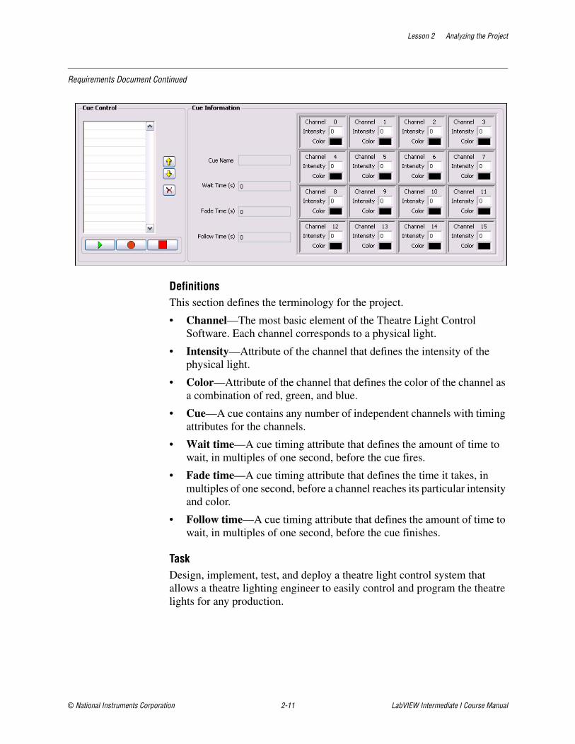
Section II: Application RequirementsIntroductionABC Theatre Lighting Inc. is the largest provider of theatre lighting systems for major metropolitan theatres worldwide. Theatre light systems must be scalable for as many lights as a particular production might require. A software-based theatre light control system allows theatres to scale the lighting for each production. The control system controls each light individually. Each light contains its own dimmer and color mixing system. The color mixing system can mix an appropriate amount of red, green, and blue to define each color. The control software sends signals to a hardware control system that controls the intensity and color of the lights. The user interface for the control software should look similar to the following front panel.
Lesson 2 Analyzing the Project
© National Instruments Corporation 2-11 LabVIEW Intermediate I Course Manual
Requirements Document Continued
DefinitionsThis section defines the terminology for the project.
• Channel—The most basic element of the Theatre Light Control Software. Each channel corresponds to a physical light.
• Intensity—Attribute of the channel that defines the intensity of the physical light.
• Color—Attribute of the channel that defines the color of the channel as a combination of red, green, and blue.
• Cue—A cue contains any number of independent channels with timing attributes for the channels.
• Wait time—A cue timing attribute that defines the amount of time to wait, in multiples of one second, before the cue fires.
• Fade time—A cue timing attribute that defines the time it takes, in multiples of one second, before a channel reaches its particular intensity and color.
• Follow time—A cue timing attribute that defines the amount of time to wait, in multiples of one second, before the cue finishes.
TaskDesign, implement, test, and deploy a theatre light control system that allows a theatre lighting engineer to easily control and program the theatre lights for any production.
Lesson 2 Analyzing the Project
LabVIEW Intermediate I Course Manual 2-12 ni.com
Requirements Document Continued
General OperationControls on the front panel control the operation of the theatre light control software. Indicators on the front panel indicate the current status of the theatre light control software.
The controller will store the channel intensity, channel color, channel wait time, channel fade time, channel follow time, and name for the cue when the user clicks the Record button. When the user clicks the Play button, the controller services each cue in the Cue Control by cycling through the recorded cues starting with the first cue in the Cue Control. A cue that is playing will wait for the specified wait time, then fade the channels to the desired color and intensity within the specified fade time, and then wait for the specified follow time. The next cue in the Cue Control is loaded and the process repeats, until all of the Cues have been played. The user can stop a currently playing cue by clicking the Stop button. The user can move a cue up in the Cue Control by clicking the Up button. The user can move a cue down in the Cue Control by clicking the Down button. The user can delete a cue from the Cue Control by clicking the Delete button, which deletes the currently selected cue. The controller exits when the user selects File»Exit.
Sequence of Operation
Application RunWhen the application starts, all of the controls must initialize to the default states as shown on the front panel. The Cue Control must be cleared to remove all of the recorded Cues. The channels must be initialized with their corresponding channel number, zero intensity, and the zero color.
RecordClick the Record button to activate the cue recording functionality. A custom panel must open that allows the lighting engineer to set the channel intensity and color for the channels. The panel must provide for the capability to name the cue, and specify the wait time, fade time, and the follow time. The minimum time for the wait time and follow time is zero seconds. The minimum time for the fade time is one second. The minimum increment for the wait time, fade time, and follow time is one second.
After a cue is recorded, the cue name is placed into the Cue Control.
Lesson 2 Analyzing the Project
© National Instruments Corporation 2-13 LabVIEW Intermediate I Course Manual
Requirements Document Continued
PlayClick the Play button to play the recorded cues. When the play begins, the controller should disable the move cue up, move cue down, delete, record, and play buttons on the front panel. The values of the first cue in the cue list is loaded into memory. The controller waits based on the number of seconds specified for the wait time for the current cue. The controller then fades the channel up or down based on the current channel intensity and the desired channel intensity. The software writes the color and intensity to the theatre lighting hardware control system, and updates the front panel channels. The controller must finish the fading within the specified fade time. The controller will finish processing the cue by waiting for the number of seconds specified for the follow time of the current cue. When the play is complete, the controller should enable the move cue up, move cue down, delete, record, and play buttons on the front panel.
StopClick the Stop button to stop a currently playing cue. The operation is ignored if a cue is not playing.
Move Cue UpClick the Move Cue Up button in the Cue Control to move a selected cue up one level in the cue list. This will swap the currently selected cue with the cue just above the currently selected cue. The operation is ignored if a cue is not selected in the cue list, or if the selected cue is the first cue in the cue list.
Move Cue DownClick the Move Cue Down button in the Cue Control to move a selected cue down one level in the cue list. This will swap the currently selected cue with the cue just below the currently selected cue. The operation is ignored if a cue is not selected in the cue list, or if the selected cue is the last cue in the cue list.
DeleteClick the Delete button to delete a selected cue in the cue list. The operation is ignored if a cue is not selected in the cue list.
SaveClick File»Save to save all of the recorded cues in a file for later playback. The user specifies the filename.
Lesson 2 Analyzing the Project
LabVIEW Intermediate I Course Manual 2-14 ni.com
Requirements Document Continued
OpenClick File»Open to open a file that contains recorded cues. The user specifies the filename.
ExitClick File»Exit to exit the application. If an error has occurred in the application, the application should report the errors.
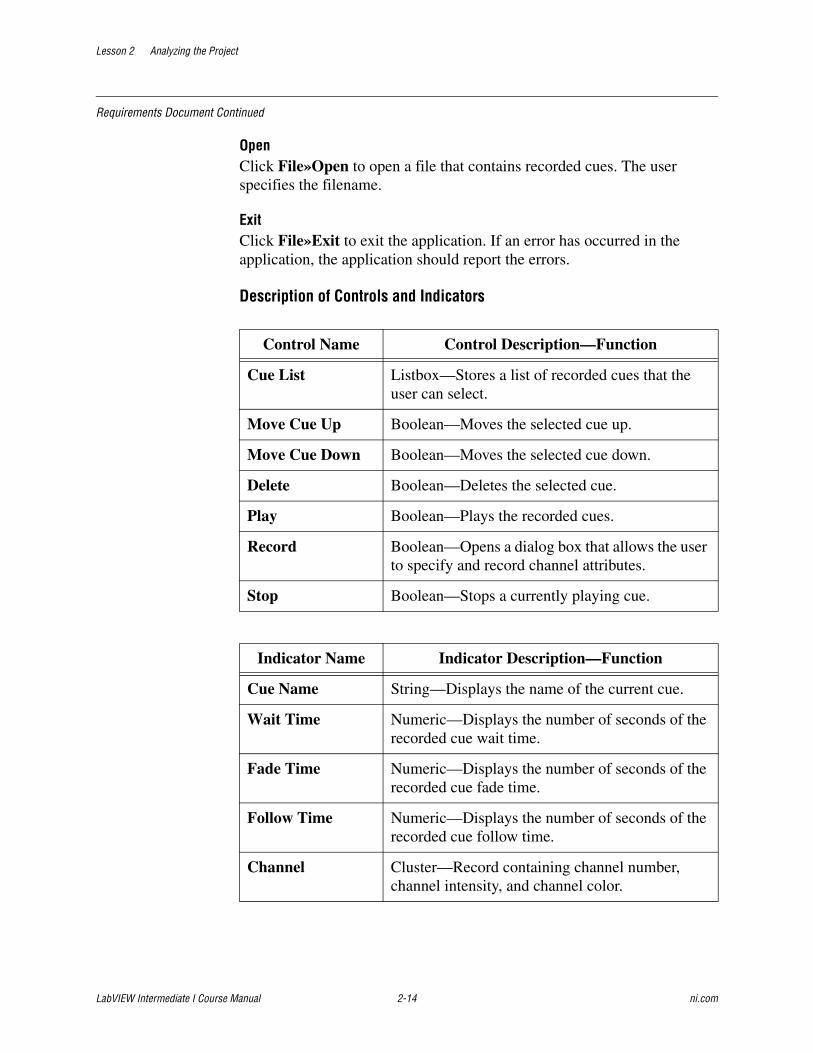
Description of Controls and Indicators
Control Name Control Description—Function
Cue List Listbox—Stores a list of recorded cues that the user can select.
Move Cue Up Boolean—Moves the selected cue up.
Move Cue Down Boolean—Moves the selected cue down.
Delete Boolean—Deletes the selected cue.
Play Boolean—Plays the recorded cues.
Record Boolean—Opens a dialog box that allows the user to specify and record channel attributes.
Stop Boolean—Stops a currently playing cue.
Indicator Name Indicator Description—Function
Cue Name String—Displays the name of the current cue.
Wait Time Numeric—Displays the number of seconds of the recorded cue wait time.
Fade Time Numeric—Displays the number of seconds of the recorded cue fade time.
Follow Time Numeric—Displays the number of seconds of the recorded cue follow time.
Channel Cluster—Record containing channel number, channel intensity, and channel color.

Lesson 2 Analyzing the Project
© National Instruments Corporation 2-15 LabVIEW Intermediate I Course Manual
Requirements Document Continued
ScalabilityMany of the newer theatre lights provide motor control to move the light around the stage. The Theatre Light Control Software should provide for the ability to easily implement channel pan and tilt. The software should be easily scalable to control any number of channels.
DocumentationThe application documentation should address the needs of the end user and a programmer who might modify the application in the future.
DeliverablesThe project includes the following deliverables:
• Documented source code
• Documentation that describes the system
TimelineThe project has the following timeline for completion:
• Day 1—User Interface prototype completed
• Day 2—Application modules completed
• Day 3—Fully functional application
End of Requirements Document
2. Use the following Requirements Document Checklist to make sure that the requirements document is complete and adequate.
❑ Each requirement is clear and understandable.
❑ Each requirement has a single, clear, unambiguous meaning.
❑ The requirements explain every functional behavior of the software system.
❑ The requirements do not contradict each other.
❑ The requirements are correct and do not specify invalid behavior.
❑ You can test each requirement.
End of Exercise 2-2
Lesson 2 Analyzing the Project
LabVIEW Intermediate I Course Manual 2-16 ni.com
D. Defining the ApplicationProject requirements describe what a software system should do. Having a set of project requirements is the next step toward developing an application. After you have communicated with the customer and finalized the specifications for the project, you can determine the project requirements. The requirements are powerful tools that tell you exactly what the software should accomplish. Therefore, the requirements must contain enough detail. If the requirements are not detailed enough, the intent of the customer could be lost and you could implement code that does not meet the needs of the customer. Determining project requirements is essential for developing a requirements document.
Before you develop a detailed design of a system, define the goals clearly. Begin by making a list of requirements. Some requirements are specific, such as the types of I/O, sampling rates, or the need for real-time analysis. Do some research at this early stage to be sure you can meet the specifications. Other requirements depend on user preferences, such as file formats or graph styles. You can take the list of requirements directly from the specifications.
Try to distinguish between absolute requirements and desires. While you can try to satisfy all requests, it is best to have an idea about which features you can sacrifice if you run out of time.
Be careful that the requirements are not so detailed that they constrain the design. For example, when you design an I/O system, the customer probably has certain sampling rate and precision requirements. However, cost also is a constraint. Include all these issues in the requirements. If you can avoid specifying the hardware, you can adjust the design after you begin prototyping and benchmarking various components. As long as the costs are within the specified budget and the timing and precision issues are met, the customer may not care whether the system uses a particular type of plug-in card or other hardware.
Another example of overly constraining a design is to be too specific about the format for display used in various screens with which the customer interacts. A picture of a display can be helpful in explaining requirements, but be clear about whether the picture is a requirement or a guideline. Some designers go through significant difficulties trying to produce a system that behaves in a specific way because a certain behavior was a requirement. In this case, there probably is a simpler solution that produces the same results at a lower cost in a shorter time period.
Lesson 2 Analyzing the Project
© National Instruments Corporation 2-17 LabVIEW Intermediate I Course Manual
One way to limit the amount of information you have to write when analyzing a project is to draw a diagram of the application. Creating a diagram helps improve your ability to design the application and convey ideas to your customer. The first step in creating a diagram is to determine the abstract components of each requirement.
Abstracting Components from RequirementsDeveloping applications that are more complex than a simple application require design techniques to realize complex items in software. Abstraction intuitively describes an application without describing how the to write the application. Abstraction generalizes the application and eliminates details.1
In general, abstraction has two categories—procedural abstraction and data abstraction.2
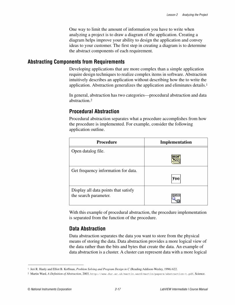
Procedural AbstractionProcedural abstraction separates what a procedure accomplishes from how the procedure is implemented. For example, consider the following application outline.
With this example of procedural abstraction, the procedure implementation is separated from the function of the procedure.
Data AbstractionData abstraction separates the data you want to store from the physical means of storing the data. Data abstraction provides a more logical view of the data rather than the bits and bytes that create the data. An example of data abstraction is a cluster. A cluster can represent data with a more logical
1. Jeri R. Hanly and Elliot B. Koffman, Problem Solving and Program Design in C (Reading:Addison-Wesley, 1996) 622.2. Martin Ward, A Definition of Abstraction, 2003, http://www.dur.ac.uk/martin.ward/martin/papers/abstraction-t.pdf, Science.
Procedure Implementation
Open datalog file.
Get frequency information for data.
Display all data points that satisfy the search parameter.

Lesson 2 Analyzing the Project
LabVIEW Intermediate I Course Manual 2-18 ni.com
view without requiring the user to be concerned with the details of its implementation.
Consider the following excerpt from the requirements document for a Theatre Light Control System. To analyze this example requirements document, extract all the nouns from the document and use the nouns to define components.
Start of Requirements Document Excerpt
TaskDesign, implement, test, and deploy a theatre light control system that allows a theatre lighting engineer to easily control and program the theatre lights for any production.
Controls on the front panel control the operation of the theatre light control software. Indicators on the front panel indicate the current status of the theatre light control software.
General OperationThe controller will store the channel intensity, channel color, channel wait time, channel fade time, channel follow time, and name for the cue when the user clicks the Record button. When the user clicks the Play button, the controller services each cue in the Cue Control by cycling through the recorded cues starting with the first cue in the Cue Control. A cue that is playing will wait for the specified wait time, then fade the channels to the desired color and intensity within the specified fade time, and then wait for the specified follow time. The user can stop a currently playing cue by clicking the Stop button. The user can move a cue up in the Cue Control by clicking the Up button. The user can move a cue down in the Cue Control by clicking the Down button. The user can delete a cue from the Cue Control by clicking the Delete button, which deletes the currently selected cue. The controller exits when the user selects File»Exit.
End of Requirements Document Excerpt
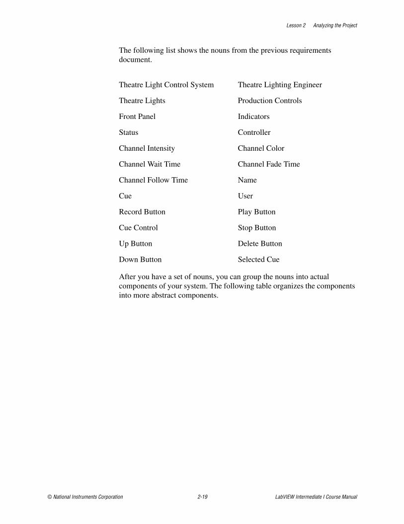
Lesson 2 Analyzing the Project
© National Instruments Corporation 2-19 LabVIEW Intermediate I Course Manual
The following list shows the nouns from the previous requirements document.
After you have a set of nouns, you can group the nouns into actual components of your system. The following table organizes the components into more abstract components.
Theatre Light Control System Theatre Lighting Engineer
Theatre Lights Production Controls
Front Panel Indicators
Status Controller
Channel Intensity Channel Color
Channel Wait Time Channel Fade Time
Channel Follow Time Name
Cue User
Record Button Play Button
Cue Control Stop Button
Up Button Delete Button
Down Button Selected Cue
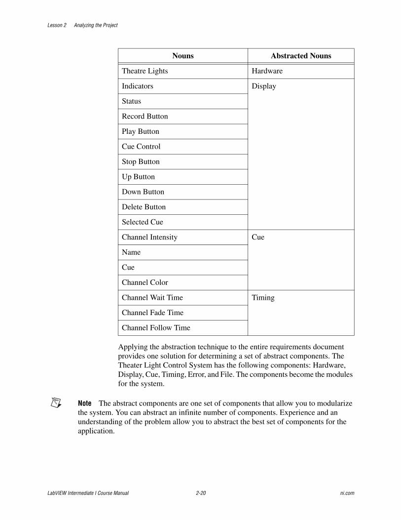
Lesson 2 Analyzing the Project
LabVIEW Intermediate I Course Manual 2-20 ni.com
Applying the abstraction technique to the entire requirements document provides one solution for determining a set of abstract components. The Theater Light Control System has the following components: Hardware, Display, Cue, Timing, Error, and File. The components become the modules for the system.
Note The abstract components are one set of components that allow you to modularize the system. You can abstract an infinite number of components. Experience and an understanding of the problem allow you to abstract the best set of components for the application.
Nouns Abstracted Nouns
Theatre Lights Hardware
Indicators Display
Status
Record Button
Play Button
Cue Control
Stop Button
Up Button
Down Button
Delete Button
Selected Cue
Channel Intensity Cue
Name
Cue
Channel Color
Channel Wait Time Timing
Channel Fade Time
Channel Follow Time
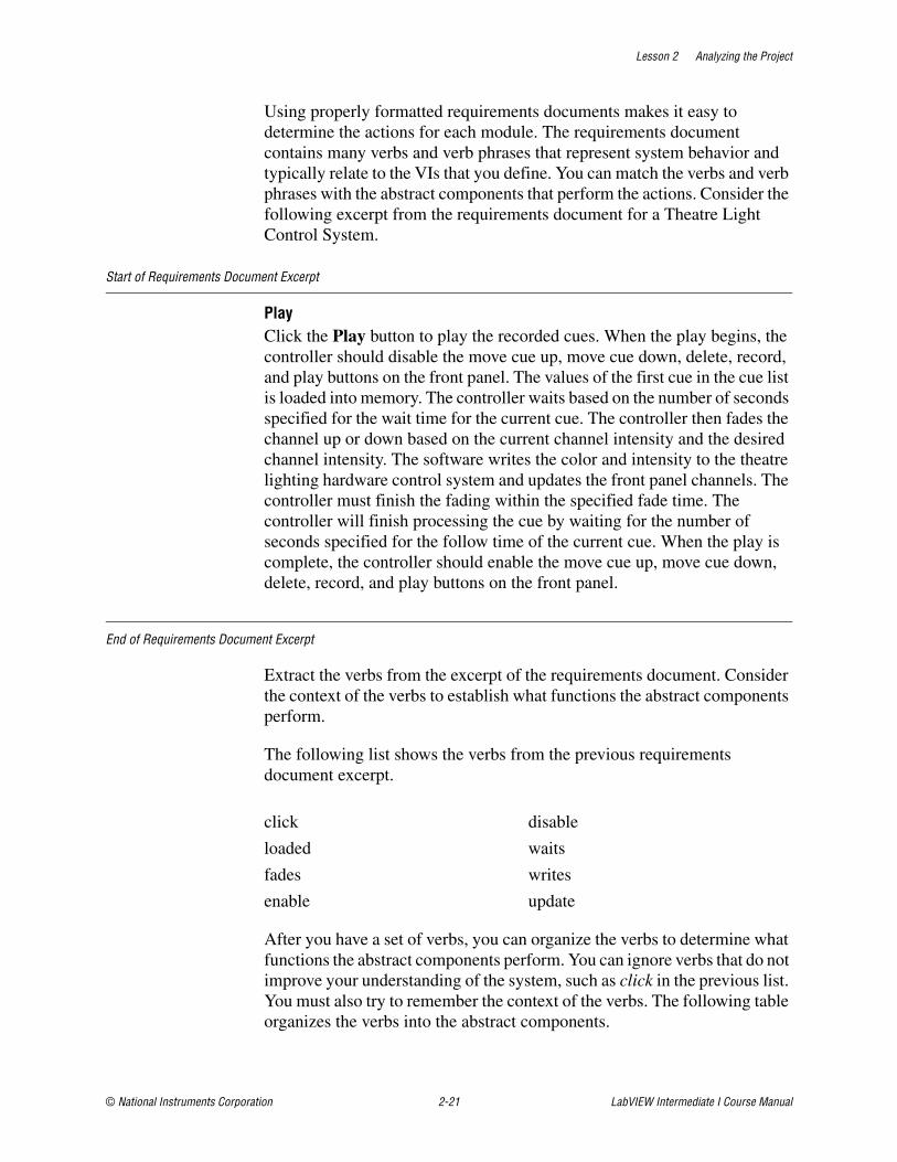
Lesson 2 Analyzing the Project
© National Instruments Corporation 2-21 LabVIEW Intermediate I Course Manual
Using properly formatted requirements documents makes it easy to determine the actions for each module. The requirements document contains many verbs and verb phrases that represent system behavior and typically relate to the VIs that you define. You can match the verbs and verb phrases with the abstract components that perform the actions. Consider the following excerpt from the requirements document for a Theatre Light Control System.
Start of Requirements Document Excerpt
PlayClick the Play button to play the recorded cues. When the play begins, the controller should disable the move cue up, move cue down, delete, record, and play buttons on the front panel. The values of the first cue in the cue list is loaded into memory. The controller waits based on the number of seconds specified for the wait time for the current cue. The controller then fades the channel up or down based on the current channel intensity and the desired channel intensity. The software writes the color and intensity to the theatre lighting hardware control system and updates the front panel channels. The controller must finish the fading within the specified fade time. The controller will finish processing the cue by waiting for the number of seconds specified for the follow time of the current cue. When the play is complete, the controller should enable the move cue up, move cue down, delete, record, and play buttons on the front panel.
End of Requirements Document Excerpt
Extract the verbs from the excerpt of the requirements document. Consider the context of the verbs to establish what functions the abstract components perform.
The following list shows the verbs from the previous requirements document excerpt.
After you have a set of verbs, you can organize the verbs to determine what functions the abstract components perform. You can ignore verbs that do not improve your understanding of the system, such as click in the previous list. You must also try to remember the context of the verbs. The following table organizes the verbs into the abstract components.
click disable
loaded waits
fades writes
enable update
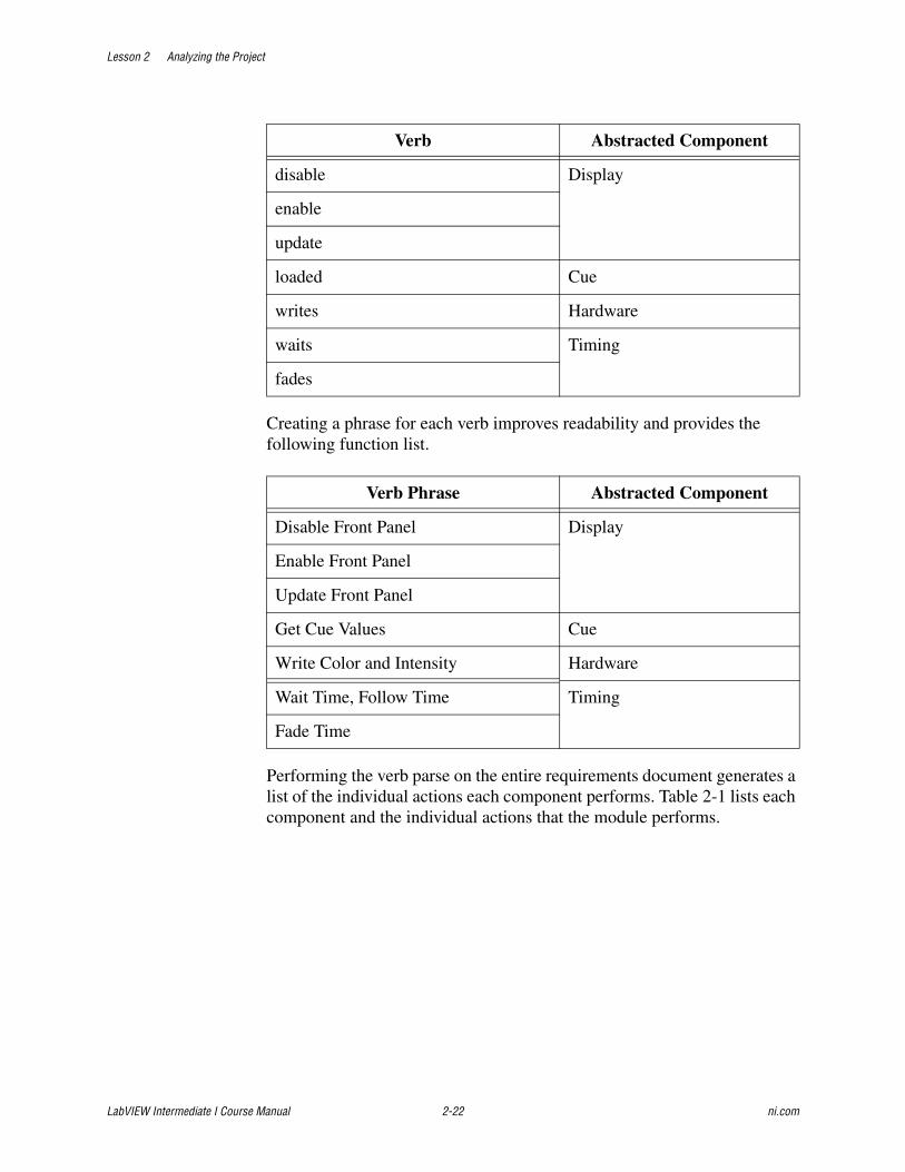
Lesson 2 Analyzing the Project
LabVIEW Intermediate I Course Manual 2-22 ni.com
Creating a phrase for each verb improves readability and provides the following function list.
Performing the verb parse on the entire requirements document generates a list of the individual actions each component performs. Table 2-1 lists each component and the individual actions that the module performs.
Verb Abstracted Component
disable Display
enable
update
loaded Cue
writes Hardware
waits Timing
fades
Verb Phrase Abstracted Component
Disable Front Panel Display
Enable Front Panel
Update Front Panel
Get Cue Values Cue
Write Color and Intensity Hardware
Wait Time, Follow Time Timing
Fade Time
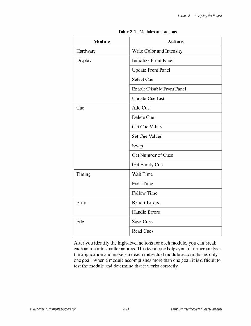
Lesson 2 Analyzing the Project
© National Instruments Corporation 2-23 LabVIEW Intermediate I Course Manual
After you identify the high-level actions for each module, you can break each action into smaller actions. This technique helps you to further analyze the application and make sure each individual module accomplishes only one goal. When a module accomplishes more than one goal, it is difficult to test the module and determine that it works correctly.
Table 2-1. Modules and Actions
Module Actions
Hardware Write Color and Intensity
Display Initialize Front Panel
Update Front Panel
Select Cue
Enable/Disable Front Panel
Update Cue List
Cue Add Cue
Delete Cue
Get Cue Values
Set Cue Values
Swap
Get Number of Cues
Get Empty Cue
Timing Wait Time
Fade Time
Follow Time
Error Report Errors
Handle Errors
File Save Cues
Read Cues
Lesson 2 Analyzing the Project
LabVIEW Intermediate I Course Manual 2-24 ni.com
If you determine that a module performs more than one goal, break the module into more modules. With this design, each module performs one specific goal. Creating a software design with this level of detail helps you develop VIs that are scalable, readable, and that consist of reusable code.
CouplingA module rarely stands by itself. A VI is called by other VIs. Top-level VIs can become plug-ins to other VIs or utilities for the operating system. Coupling refers to the connections that exist between modules. Any module that relies on another module to perform some function is coupled to that module. If one module does not function correctly, other modules to which it is coupled do not function correctly. The more connections among modules, the harder it is to determine what module causes a problem. Coupling measures how many dependencies a system of modules contains.
The fewer outputs a module exposes, the more you can change the code inside the module without breaking other modules. Low coupling also helps make bug tracking more efficient. For example, a data acquisition bug cannot occur in a VI that performs only GPIB instrument control. If a data acquisition bug appears in a GPIB VI, you know the code is probably too tightly coupled.
The dataflow model of LabVIEW automatically encourages low coupling among modules. The dataflow model means each VI has only the information it needs to do its job. A VI cannot change data in another VI. You can introduce other communication paths, such as global variables, queues, I/O connections, and so on, that can increase coupling, but a typical VI is self-sufficient and couples only to the subVIs it calls. The goal of any hierarchical architecture is to make sure that the implementation uses low or loose coupling.
CohesionIn a well-designed VI, each module fulfills one goal and thus is strongly cohesive. If a single module tries to fulfill more than one goal, you should probably break it into modules. When a module tries to accomplish multiple goals, the block diagram becomes harder to read, and the code for one goal can affect how the code for another goal works. In this case, fixing a bug in one goal might break the code of another goal.
A VI with strong cohesion has one goal per module. Strong cohesion decreases overall development time. You can more easily understand a single module if it focuses on one task. You can read a clean, uncomplicated block diagram quickly and make deliberate changes with confidence.
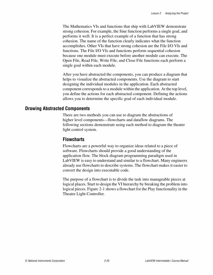
Lesson 2 Analyzing the Project
© National Instruments Corporation 2-25 LabVIEW Intermediate I Course Manual
The Mathematics VIs and functions that ship with LabVIEW demonstrate strong cohesion. For example, the Sine function performs a single goal, and performs it well. It is a perfect example of a function that has strong cohesion. The name of the function clearly indicates what the function accomplishes. Other VIs that have strong cohesion are the File I/O VIs and functions. The File I/O VIs and functions perform sequential cohesion because one module must execute before another module can execute. The Open File, Read File, Write File, and Close File functions each perform a single goal within each module.
After you have abstracted the components, you can produce a diagram that helps to visualize the abstracted components. Use the diagram to start designing the individual modules in the application. Each abstracted component corresponds to a module within the application. At the top level, you define the actions for each abstracted component. Defining the actions allows you to determine the specific goal of each individual module.
Drawing Abstracted ComponentsThere are two methods you can use to diagram the abstractions of higher level components—flowcharts and dataflow diagrams. The following sections demonstrate using each method to diagram the theater light control system.
FlowchartsFlowcharts are a powerful way to organize ideas related to a piece of software. Flowcharts should provide a good understanding of the application flow. The block diagram programming paradigm used in LabVIEW is easy to understand and similar to a flowchart. Many engineers already use flowcharts to describe systems. The flowchart makes it easier to convert the design into executable code.
The purpose of a flowchart is to divide the task into manageable pieces at logical places. Start to design the VI hierarchy by breaking the problem into logical pieces. Figure 2-1 shows a flowchart for the Play functionality in the Theatre Light Controller.
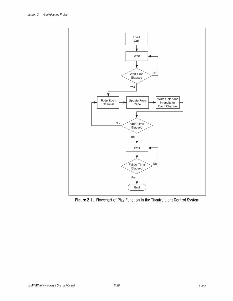
Lesson 2 Analyzing the Project
LabVIEW Intermediate I Course Manual 2-26 ni.com
Figure 2-1. Flowchart of Play Function in the Theatre Light Control System
Load Cue
Fade TimeElapsed
Wait
Fade EachChannel
Update FrontPanel
Wait
Write Color andIntensity to
Each Channel
Follow TimeElapsed
Wait TimeElapsed
No
No
End
No
Yes
Yes
Yes
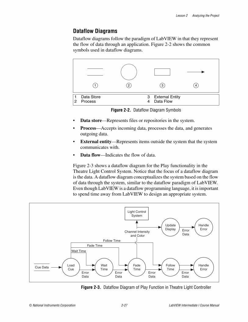
Lesson 2 Analyzing the Project
© National Instruments Corporation 2-27 LabVIEW Intermediate I Course Manual
Dataflow DiagramsDataflow diagrams follow the paradigm of LabVIEW in that they represent the flow of data through an application. Figure 2-2 shows the common symbols used in dataflow diagrams.
Figure 2-2. Dataflow Diagram Symbols
• Data store—Represents files or repositories in the system.
• Process—Accepts incoming data, processes the data, and generates outgoing data.
• External entity—Represents items outside the system that the system communicates with.
• Data flow—Indicates the flow of data.
Figure 2-3 shows a dataflow diagram for the Play functionality in the Theatre Light Control System. Notice that the focus of a dataflow diagram is the data. A dataflow diagram conceptualizes the system based on the flow of data through the system, similar to the dataflow paradigm of LabVIEW. Even though LabVIEW is a dataflow programming language, it is important to spend time away from LabVIEW to design an appropriate system.
Figure 2-3. Dataflow Diagram of Play Function in Theatre Light Controller
1 Data Store2 Process
3 External Entity4 Data Flow
1 2 3 4
Light ControlSystem
LoadCue
WaitTime
FadeTime
FollowTime
HandleError
Channel Intensity and Color
UpdateDisplay
HandleErrorError
Data
ErrorData
ErrorData
Wait Time
ErrorData
Cue Data
ErrorData
Fade Time
Follow Time

Lesson 2 Analyzing the Project
LabVIEW Intermediate I Course Manual 2-28 ni.com
As you can see by the differences in the flowchart and the dataflow diagram of the Play function in the Theatre Light Controller, the processes are different. Nodes in the flowchart represent the functions to perform. Nodes in the dataflow diagram represent the processes and the focus is on the flow of data through the system. You can translate a dataflow diagram into a LabVIEW block diagram.

Lesson 2 Analyzing the Project
© National Instruments Corporation 2-29 LabVIEW Intermediate I Course Manual
Summary• Specifications define what the customer wants to achieve with the
software, or what functions the application should perform.
• You must interact with the customer closely to make sure the specifications document contains all the necessary information.
• Project requirements describe a software system.
• Abstraction intuitively describes an application without describing how to write the application.
• Abstraction generalizes the application and eliminates details.
• Creating a diagram helps improve your ability to design the application and convey ideas to your customer.
• Requirements documents provide a common ground for you and the customer to work from.

Lesson 2 Analyzing the Project
LabVIEW Intermediate I Course Manual 2-30 ni.com
Notes
© National Instruments Corporation 3-1 LabVIEW Intermediate I Course Manual
3Designing the User Interface
Front panels must be well organized and easy to use because users see the front panel first when working with a VI. When designing a front panel, keep in mind two types of users—the end user and the developer. End users work with user interface VIs, which have front panels that the end user sees. Developers work with subVIs, which have front panels that only developers see.
At the end of this lesson, you design a user interface for a software project that you analyzed.
TopicsA. User Interface Design IssuesB. User Interface Layout Issues
C. Front Panel Prototyping
D. User Interface Example
E. Localizing User Interfaces
Lesson 3 Designing the User Interface
LabVIEW Intermediate I Course Manual 3-2 ni.com
A. User Interface Design IssuesWhen designing a front panel for a user interface, choose fonts, colors, and graphics carefully to make the user interface more intuitive and easy to use.
Fonts and Text CharacteristicsLimit the VI to the three standard fonts (application, system, and dialog) unless you have a specific reason to use a different font. For example, monospace fonts, which are fonts that are proportionally spaced, are useful for string controls and indicators where the number of characters is critical.
Refer to the LabVIEW Help for more information about setting the default font, using custom fonts, and changing the font style.
The actual font used for the three standard fonts (application, system, and dialog) varies depending on the platform. For example, when working on Windows, preferences and video driver settings affect the size of the fonts. Text might appear larger or smaller on different systems, depending on these factors. To compensate for this, allow extra space for larger fonts and enable the Size to Text option on the shortcut menu.
Allow extra space between controls to prevent labels from overlapping objects because of font changes on multiple platforms.
For example, if a label is to the left of an object, justify the label to the right and leave some space to the left of the text. If you center a label over or under an object, center the text of that label as well. Fonts are the least portable aspect of the front panel so always test them on all target platforms.
ColorsColor can distract the user from important information. For instance, a yellow, green, or bright orange background makes it difficult to see a red danger light. Another problem is that some platforms do not have as many colors available. Use a minimal number of colors, emphasizing black, white, and gray. The following are some simple guidelines for using color:
• Never use color as the sole indicator of device state. People with some degree of color-blindness can have problems detecting the change. Also, multiplot graphs and charts can lose meaning when displayed in black and white. Use lines for plot styles in addition to color.
• Consider coloring the front panel background and objects of user interface VIs with the system colors, or symbolic colors, in the color picker. System colors adapt the appearance of the front panel to the system colors of any computer that runs the VI.
• Use light gray, white, or pastel colors for backgrounds. The first row of colors in the color picker contains less harsh colors suitable for front
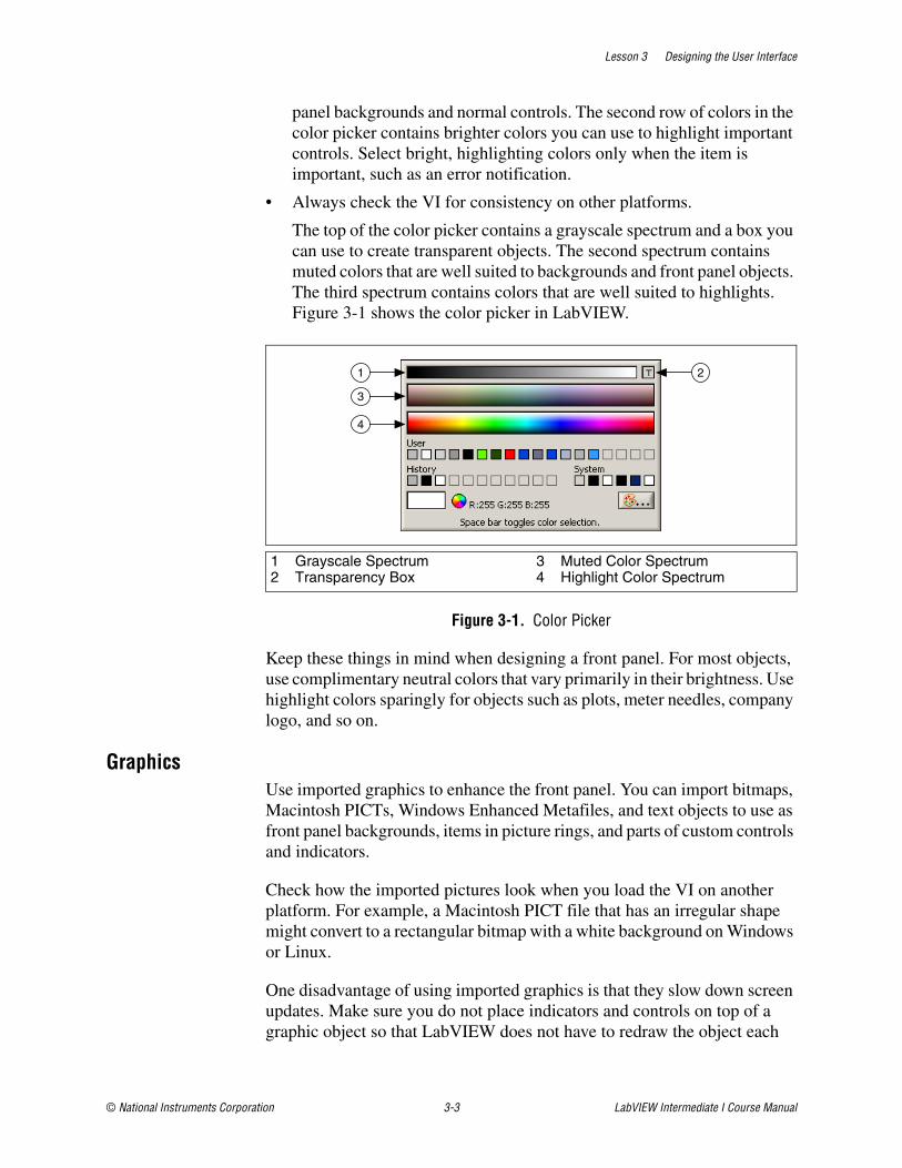
Lesson 3 Designing the User Interface
© National Instruments Corporation 3-3 LabVIEW Intermediate I Course Manual
panel backgrounds and normal controls. The second row of colors in the color picker contains brighter colors you can use to highlight important controls. Select bright, highlighting colors only when the item is important, such as an error notification.
• Always check the VI for consistency on other platforms.
The top of the color picker contains a grayscale spectrum and a box you can use to create transparent objects. The second spectrum contains muted colors that are well suited to backgrounds and front panel objects. The third spectrum contains colors that are well suited to highlights. Figure 3-1 shows the color picker in LabVIEW.
Figure 3-1. Color Picker
Keep these things in mind when designing a front panel. For most objects, use complimentary neutral colors that vary primarily in their brightness. Use highlight colors sparingly for objects such as plots, meter needles, company logo, and so on.
GraphicsUse imported graphics to enhance the front panel. You can import bitmaps, Macintosh PICTs, Windows Enhanced Metafiles, and text objects to use as front panel backgrounds, items in picture rings, and parts of custom controls and indicators.
Check how the imported pictures look when you load the VI on another platform. For example, a Macintosh PICT file that has an irregular shape might convert to a rectangular bitmap with a white background on Windows or Linux.
One disadvantage of using imported graphics is that they slow down screen updates. Make sure you do not place indicators and controls on top of a graphic object so that LabVIEW does not have to redraw the object each
1 Grayscale Spectrum2 Transparency Box
3 Muted Color Spectrum4 Highlight Color Spectrum
1
3
4
2
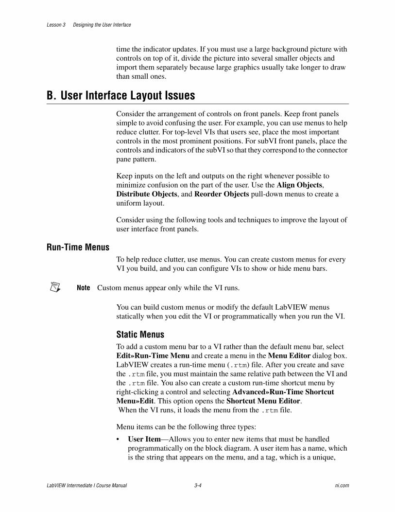
Lesson 3 Designing the User Interface
LabVIEW Intermediate I Course Manual 3-4 ni.com
time the indicator updates. If you must use a large background picture with controls on top of it, divide the picture into several smaller objects and import them separately because large graphics usually take longer to draw than small ones.
B. User Interface Layout IssuesConsider the arrangement of controls on front panels. Keep front panels simple to avoid confusing the user. For example, you can use menus to help reduce clutter. For top-level VIs that users see, place the most important controls in the most prominent positions. For subVI front panels, place the controls and indicators of the subVI so that they correspond to the connector pane pattern.
Keep inputs on the left and outputs on the right whenever possible to minimize confusion on the part of the user. Use the Align Objects, Distribute Objects, and Reorder Objects pull-down menus to create a uniform layout.
Consider using the following tools and techniques to improve the layout of user interface front panels.
Run-Time MenusTo help reduce clutter, use menus. You can create custom menus for every VI you build, and you can configure VIs to show or hide menu bars.
Note Custom menus appear only while the VI runs.
You can build custom menus or modify the default LabVIEW menus statically when you edit the VI or programmatically when you run the VI.
Static MenusTo add a custom menu bar to a VI rather than the default menu bar, select Edit»Run-Time Menu and create a menu in the Menu Editor dialog box. LabVIEW creates a run-time menu (.rtm) file. After you create and save the .rtm file, you must maintain the same relative path between the VI and the .rtm file. You also can create a custom run-time shortcut menu by right-clicking a control and selecting Advanced»Run-Time Shortcut Menu»Edit. This option opens the Shortcut Menu Editor. When the VI runs, it loads the menu from the .rtm file.
Menu items can be the following three types:
• User Item—Allows you to enter new items that must be handled programmatically on the block diagram. A user item has a name, which is the string that appears on the menu, and a tag, which is a unique,

Lesson 3 Designing the User Interface
© National Instruments Corporation 3-5 LabVIEW Intermediate I Course Manual
case-insensitive string identifier. The tag identifies the user item on the block diagram. When you type a name, LabVIEW copies it to the tag. You can edit the tag to be different from the name. For a menu item to be valid, its tag must have a value. The Item Tag text box displays question marks for invalid menu items. LabVIEW ensures that the tag is unique to a menu hierarchy and appends numbers when necessary.
• Separator—Inserts a separation line on the menu. You cannot set any attributes for this item.
• Application Item—Allows you to select default menu items. To insert a menu item, select Application Item and follow the hierarchy to the items you want to add. Add individual items or entire submenus. LabVIEW handles application items automatically. These item tags do not appear in block diagrams. You cannot alter the name, tag, or other properties of an application item. LabVIEW reserves the prefix APP_ for application item tags.
Click the blue + button, shown at left, on the toolbar to add more items to the custom menu. Click the red X button, shown at left, to delete items. You can arrange the menu hierarchy by clicking the arrow buttons in the toolbar, using the hierarchy manipulation options in the Edit menu, or by dragging and dropping.
Menu Selection HandlingUse the functions located on the top row of the Menu palette to handle menu selections.
When you create a custom menu, you assign each menu item a unique, case-insensitive string identifier called a tag. When the user selects a menu item, you retrieve its tag programmatically using the Get Menu Selection function. LabVIEW provides a handler on the block diagram for each menu item based on the tag value of each menu item. The handler is a While Loop and Case structure combination that allows you to determine which, if any, menu is selected and to execute the appropriate code.
After you build a custom menu, build a Case structure on the block diagram that executes, or handles, each item in the custom menu. This process is called menu selection handling. LabVIEW handles all application items implicitly.
Use the Get Menu Selection and Enable Menu Tracking functions to define what actions to take when users select each menu item.
Lesson 3 Designing the User Interface
LabVIEW Intermediate I Course Manual 3-6 ni.com
Run-Time Shortcut MenusYou can customize the run-time shortcut menu for each control you include in a VI. To customize a shortcut menu, right-click a control and select Advanced»Run-Time Shortcut Menu»Edit from the shortcut menu to display the Shortcut Menu Editor dialog box. Use the Shortcut Menu Editor dialog box to associate the default shortcut menu or a customized shortcut menu file (.rtm) with the control. You can customize shortcut menus programmatically.
You also can add shortcut menus to front panels. To add a shortcut menu to the front panel, use the Shortcut Menu Activation and Shortcut Menu Selection pane events.
You also can disable the run-time shortcut menu on a control.
Note Custom run-time shortcut menus appear only while the VI runs.
DecorationsUse decorations, such as a Raised Box or Horizontal Smooth Box, to visually group objects with related functions.
Figure 3-2. Using Decorations to Visually Group Objects
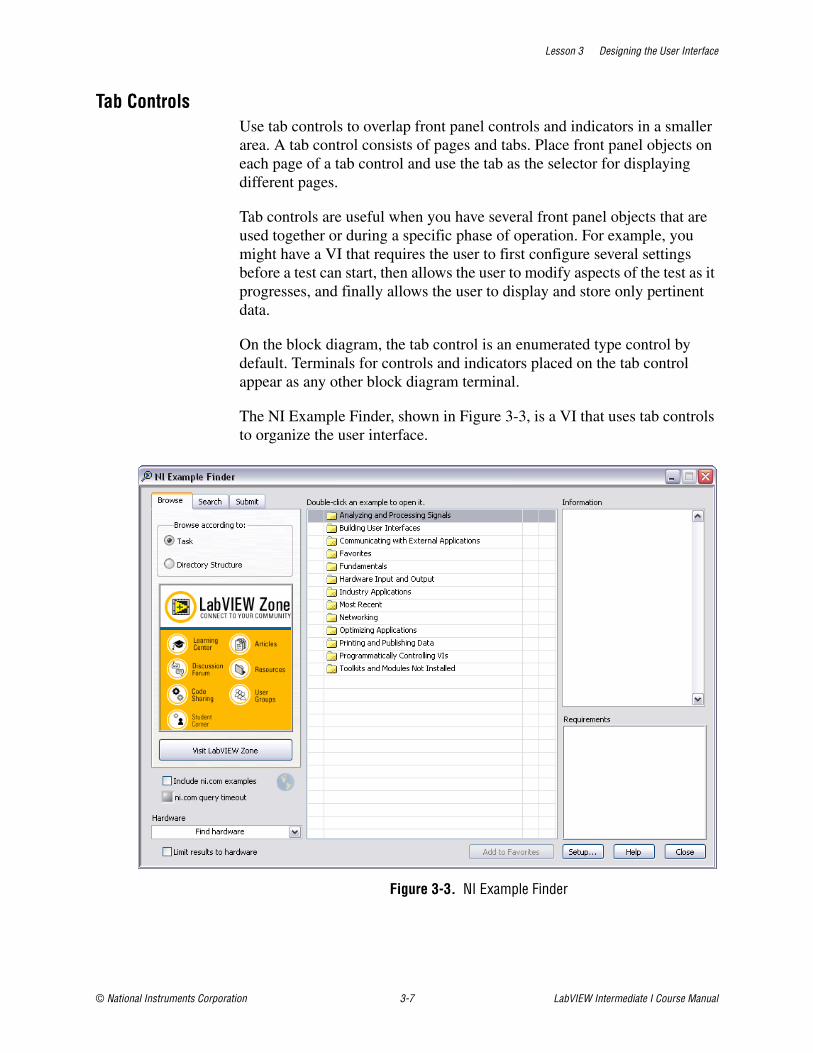
Lesson 3 Designing the User Interface
© National Instruments Corporation 3-7 LabVIEW Intermediate I Course Manual
Tab ControlsUse tab controls to overlap front panel controls and indicators in a smaller area. A tab control consists of pages and tabs. Place front panel objects on each page of a tab control and use the tab as the selector for displaying different pages.
Tab controls are useful when you have several front panel objects that are used together or during a specific phase of operation. For example, you might have a VI that requires the user to first configure several settings before a test can start, then allows the user to modify aspects of the test as it progresses, and finally allows the user to display and store only pertinent data.
On the block diagram, the tab control is an enumerated type control by default. Terminals for controls and indicators placed on the tab control appear as any other block diagram terminal.
The NI Example Finder, shown in Figure 3-3, is a VI that uses tab controls to organize the user interface.
Figure 3-3. NI Example Finder
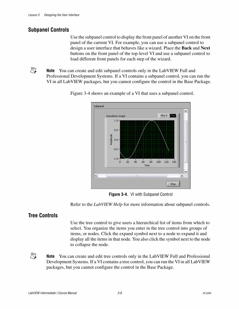
Lesson 3 Designing the User Interface
LabVIEW Intermediate I Course Manual 3-8 ni.com
Subpanel ControlsUse the subpanel control to display the front panel of another VI on the front panel of the current VI. For example, you can use a subpanel control to design a user interface that behaves like a wizard. Place the Back and Next buttons on the front panel of the top-level VI and use a subpanel control to load different front panels for each step of the wizard.
Note You can create and edit subpanel controls only in the LabVIEW Full and Professional Development Systems. If a VI contains a subpanel control, you can run the VI in all LabVIEW packages, but you cannot configure the control in the Base Package.
Figure 3-4 shows an example of a VI that uses a subpanel control.
Figure 3-4. VI with Subpanel Control
Refer to the LabVIEW Help for more information about subpanel controls.
Tree ControlsUse the tree control to give users a hierarchical list of items from which to select. You organize the items you enter in the tree control into groups of items, or nodes. Click the expand symbol next to a node to expand it and display all the items in that node. You also click the symbol next to the node to collapse the node.
Note You can create and edit tree controls only in the LabVIEW Full and Professional Development Systems. If a VI contains a tree control, you can run the VI in all LabVIEW packages, but you cannot configure the control in the Base Package.
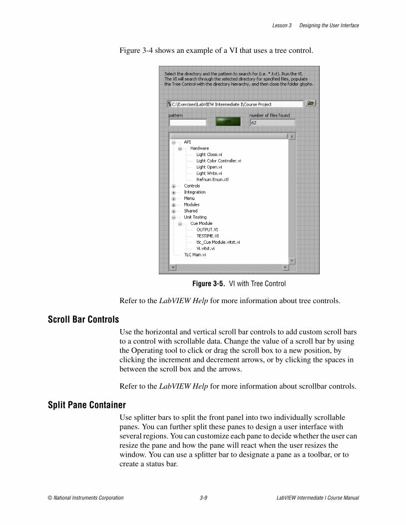
Lesson 3 Designing the User Interface
© National Instruments Corporation 3-9 LabVIEW Intermediate I Course Manual
Figure 3-4 shows an example of a VI that uses a tree control.
Figure 3-5. VI with Tree Control
Refer to the LabVIEW Help for more information about tree controls.
Scroll Bar ControlsUse the horizontal and vertical scroll bar controls to add custom scroll bars to a control with scrollable data. Change the value of a scroll bar by using the Operating tool to click or drag the scroll box to a new position, by clicking the increment and decrement arrows, or by clicking the spaces in between the scroll box and the arrows.
Refer to the LabVIEW Help for more information about scrollbar controls.
Split Pane ContainerUse splitter bars to split the front panel into two individually scrollable panes. You can further split these panes to design a user interface with several regions. You can customize each pane to decide whether the user can resize the pane and how the pane will react when the user resizes the window. You can use a splitter bar to designate a pane as a toolbar, or to create a status bar.
Lesson 3 Designing the User Interface
LabVIEW Intermediate I Course Manual 3-10 ni.com
Refer to the LabVIEW Help for more information about split pane containers. Refer to the Creating Custom Toolbars section of Exercise 3-1 for an example that uses the split pane container to create a toolbar.
Transparent Front PanelsYou can use the Front Panel Window:Transparency property to set the window transparency while the VI is running. The level of transparency is a percentage where 0 is opaque and 100 is invisible. This property returns an error if you specify a value outside the range of 0 to 100.
Refer to the LabVIEW Help for more information about the Front Panel Window:Transparency property.
Drag and DropYou can use drag and drop to provide an alternative way to move data between controls in LabVIEW. Drag and drop is a common way for users to interact with the user interface in a modern application. It is essentially an operation between two controls: the drag source, and the drop target.
The drag source is the control that provides the data to the drag and drop operation. Some LabVIEW controls, like string and tree controls, automatically act as drag sources when you drag from them. For these controls, you can use the Drag Starting? event to provide more control over what the user drags.
For controls that do not act as drag sources, you can build custom drag sources by using the control method Start Drag. With this method, you can start a drag and drop operation whenever required and provide data types specific for your application.
The drag source also controls the appearance of the cursor during a drag and drop operation. LabVIEW uses system defined drag and drop cursors (Mac and Windows) or LabVIEW defined cursors (Linux). Use the Drag Source Update event to provide custom cursor feedback for your application.
Finally, the drag source is responsible for moving the data after a successful drag and drop operation. Some LabVIEW drag sources automatically handle moving data for drag move drag and drop operations. Use the Drag Ended event to complete drag move operations for user defined drag data types.
The drop target is the control that accepts the data from the drag and drop operation. Some LabVIEW controls, like the string, path, and tree control automatically act as drop targets when a drag occurs over them and the drag source provides the appropriate data. These controls accept special built in data types, defined by LabVIEW, with no programming required.
Lesson 3 Designing the User Interface
© National Instruments Corporation 3-11 LabVIEW Intermediate I Course Manual
Creating a Drag and Drop OperationThe first phase of a drag and drop operation is to select the Drag Source object, the data types to publish, and whether the drag should support moving. For some controls, LabVIEW chooses these parameters automatically:
String Control
Data Provided: (LV_TEXT, String)
Allows Move: TRUE, if control, otherwise FALSE
Tree Control
Data Provided: (LV_TEXT, String), (LV_TREE_TAG, String)
Allows Move: TRUE
Start a drag and drop operation from a built in drag source by dragging from the control. For a string control, select text, then click and drag with the Operating tool. For a tree control, select a tree item, then drag the item from the tree control.
For a control with no built in drag source behavior defined, the application must provide the information necessary to start the drag and drop operation. Use the Start Drag method on a control to specify the data for the drag and drop operation, if the drag source supports moving the drag data, and to start the drag and drop.
The second phase of the drag and drop operation is finding a suitable drop target for the drag data.
LabVIEW uses default behavior to determine if the drop will be successful. The string control will accept the drop if the LV_TEXT data type is available. The tree control will also accept the drop if the LV_TEXT or LV_TREE_TAG data type is available. The path control will accept the drop if the LV_PATH data type is provided. All other controls will automatically report that they will not accept the drag.
Refer to the LabVIEW Help for more information about drag and drop.
Sizing and PositioningFront panels need to fit on a monitor that is the standard resolution for most intended users. Make the window as small as possible without crowding controls or sacrificing a clear layout. If the VIs are for in-house use and everyone is using high-resolution display settings, you can design large front panels. If you are doing commercial development, keep in mind that some displays have a limited resolution, especially LCD displays and touchscreens.
Lesson 3 Designing the User Interface
LabVIEW Intermediate I Course Manual 3-12 ni.com
Front panels should open in the upper-left corner of the screen for the convenience of users with small screens. Place sets of VIs that are often opened together so the user can see at least a small part of each. Place front panels that open automatically in the center of the screen. Centering the front panels makes the VI easier to read for users on monitors of various sizes. Use the VI Properties dialog box to customize the window appearance and size.
Labels and CaptionsEffective use of labels and captions can improve the ease of use of user interface front panels.
LabelsThe name of a control or indicator should describe its function. If the control is visible to the user, use captions to display a long description and add a short label to prevent using valuable space on the block diagram. For example, when labeling a ring control or slide control that has options for volts, ohms, or amperes, select an intuitive name for the control. A caption such as "Select units for display" is a better choice than "V/O/A". Use Property Nodes to change captions programmatically.
Use consistent capitalization, and include default values and unit information in label names. For example, if a control sets the high limit temperature and has a default value of 75 °F, name the control high limit temperature (75 degF). If you will use the VI with the control on multiple platforms, avoid using special characters in control names. For example, use degF instead of °F, because the ° symbol might not display correctly on other platforms.
For Boolean controls, use the name to give an indication of which state corresponds to which function and to indicate the default state. For checkboxes and radio buttons, the user can click the Boolean text of the control and the value of the Boolean control changes. Free labels next to a Boolean control can help clarify the meaning of each position on a switch. For example, use free labels like Cancel, Reset, and Initialize that describe the action taken.
The Context Help window displays labels as part of the connector pane. If the default value is essential information, place the value in parentheses next to the name in the label. Include the units of the value if applicable.
The Required, Recommended, Optional setting for connector pane terminals affects the appearance of the inputs and outputs in the Context Help window.
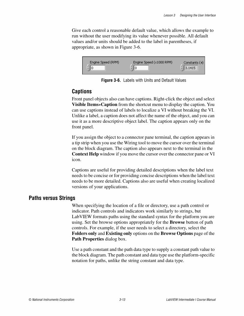
Lesson 3 Designing the User Interface
© National Instruments Corporation 3-13 LabVIEW Intermediate I Course Manual
Give each control a reasonable default value, which allows the example to run without the user modifying its value whenever possible. All default values and/or units should be added to the label in parentheses, if appropriate, as shown in Figure 3-6.
Figure 3-6. Labels with Units and Default Values
CaptionsFront panel objects also can have captions. Right-click the object and select Visible Items»Caption from the shortcut menu to display the caption. You can use captions instead of labels to localize a VI without breaking the VI. Unlike a label, a caption does not affect the name of the object, and you can use it as a more descriptive object label. The caption appears only on the front panel.
If you assign the object to a connector pane terminal, the caption appears in a tip strip when you use the Wiring tool to move the cursor over the terminal on the block diagram. The caption also appears next to the terminal in the Context Help window if you move the cursor over the connector pane or VI icon.
Captions are useful for providing detailed descriptions when the label text needs to be concise or for providing concise descriptions when the label text needs to be more detailed. Captions also are useful when creating localized versions of your applications.
Paths versus StringsWhen specifying the location of a file or directory, use a path control or indicator. Path controls and indicators work similarly to strings, but LabVIEW formats paths using the standard syntax for the platform you are using. Set the browse options appropriately for the Browse button of path controls. For example, if the user needs to select a directory, select the Folders only and Existing only options on the Browse Options page of the Path Properties dialog box.
Use a path constant and the path data type to supply a constant path value to the block diagram. The path constant and data type use the platform-specific notation for paths, unlike the string constant and data type.
Lesson 3 Designing the User Interface
LabVIEW Intermediate I Course Manual 3-14 ni.com
Default Values and RangesExpect the user to supply invalid values to every control. You can check for invalid values on the block diagram or right-click the control and select Data Range to set the control item to coerce values into the desired range: Minimum, Maximum, and Increment.
A VI should not fail when run with default values. Do not set default values of indicators like graphs, arrays, and strings without a good reason because that wastes disk space when saving the VI.
Use default values intelligently. In the case of many File I/O VIs and functions, such as the Write to Spreadsheet File VI, the default is an empty path that forces the VI to display a file dialog box. This can save the use of a Boolean switch in many cases.
You can handle difficult situations programmatically. Many GPIB instruments limit the permissible settings of one control based on the settings of another. For example, a voltmeter might permit a range setting of 2,000 V for DC but only 1,000 V for AC. If the affected controls like Range and Mode reside in the same VI, place the interlock logic there.
Key NavigationSome users prefer to use the keyboard instead of a mouse. In some environments, such as a manufacturing plant, only a keyboard is available. Consider including keyboard shortcuts for VIs even if the use of a mouse is available because keyboard shortcuts add convenience to a VI.
Pay attention to the key navigation options for objects on the front panel and set the tabbing order for the objects to read left to right and top to bottom. Set the <Enter> key as the keyboard shortcut for the front panel default control, which is usually the OK button. However, if you have a multiline string control on the front panel, you might not want to use the <Enter> key as a shortcut.
If the front panel has a Cancel button, set the <Esc> key to be the keyboard shortcut. You also can use function keys as navigation buttons to move from screen to screen. If you do this, be sure to use the shortcuts consistently. Select Edit»Set Tabbing Order to arrange controls in a logical sequence when the user needs to tab between the controls. For controls that are offscreen, use the Key Navigation tab of the Properties dialog box to skip over the controls when tabbing or to hide the controls.
Also consider using the key focus property to set the focus programmatically to a specific control when the front panel opens.

Lesson 3 Designing the User Interface
© National Instruments Corporation 3-15 LabVIEW Intermediate I Course Manual
Front Panel Object StylesYou can choose controls and objects from different palettes when you build a user interface. Figure 3-7 shows three examples of the same user interface, each built using controls and objects from different palettes.
Front panel controls and indicators can appear in modern, classic, or system style.
Many front panel objects have a high-color appearance. Set the monitor to display at least 16-bit color for optimal appearance of the objects.
The controls and indicators located on the Modern palette also have corresponding low-color objects. Use the controls and indicators located on the Classic palette to create VIs for 256-color and 16-color monitor settings.
The first example in Figure 3-7 uses controls from the Modern palette. The second example in Figure 3-7 uses controls from the Classic palette. You also can use Classic controls for VIs that require an efficient user interface.
Figure 3-7. User Interface Control Styles
Use the system controls and indicators located on the System palette in dialog boxes you create. The system controls and indicators are designed specifically for use in dialog boxes and include ring and spin controls, numeric slides, progress bars, scroll bars, listboxes, tables, string and path controls, tab controls, tree controls, buttons, checkboxes, radio buttons, and an opaque label that automatically matches the background color of its
1 User Interface Built Using Modern Controls2 User Interface Built Using Classic Controls
3 User Interface Built Using System Controls
1 2 3
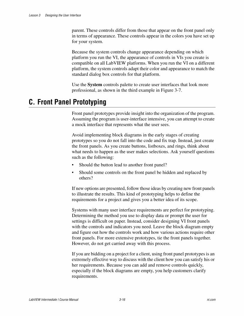
Lesson 3 Designing the User Interface
LabVIEW Intermediate I Course Manual 3-16 ni.com
parent. These controls differ from those that appear on the front panel only in terms of appearance. These controls appear in the colors you have set up for your system.
Because the system controls change appearance depending on which platform you run the VI, the appearance of controls in VIs you create is compatible on all LabVIEW platforms. When you run the VI on a different platform, the system controls adapt their color and appearance to match the standard dialog box controls for that platform.
Use the System controls palette to create user interfaces that look more professional, as shown in the third example in Figure 3-7.
C. Front Panel PrototypingFront panel prototypes provide insight into the organization of the program. Assuming the program is user-interface intensive, you can attempt to create a mock interface that represents what the user sees.
Avoid implementing block diagrams in the early stages of creating prototypes so you do not fall into the code and fix trap. Instead, just create the front panels. As you create buttons, listboxes, and rings, think about what needs to happen as the user makes selections. Ask yourself questions such as the following:
• Should the button lead to another front panel?
• Should some controls on the front panel be hidden and replaced by others?
If new options are presented, follow those ideas by creating new front panels to illustrate the results. This kind of prototyping helps to define the requirements for a project and gives you a better idea of its scope.
Systems with many user interface requirements are perfect for prototyping. Determining the method you use to display data or prompt the user for settings is difficult on paper. Instead, consider designing VI front panels with the controls and indicators you need. Leave the block diagram empty and figure out how the controls work and how various actions require other front panels. For more extensive prototypes, tie the front panels together. However, do not get carried away with this process.
If you are bidding on a project for a client, using front panel prototypes is an extremely effective way to discuss with the client how you can satisfy his or her requirements. Because you can add and remove controls quickly, especially if the block diagrams are empty, you help customers clarify requirements.

Lesson 3 Designing the User Interface
© National Instruments Corporation 3-17 LabVIEW Intermediate I Course Manual
Limit the amount of time you spend prototyping before you begin. Time limits help to avoid overdoing the prototyping phase. As you incorporate changes, update the requirements and the current design.
D. User Interface ExampleWithout proper planning, it is easy to produce a user interface that does not incorporate good front panel design. Figure 3-8 shows an example of a poorly designed user interface.
Figure 3-8. Poorly Designed User Interface
Figure 3-9 shows the same user interface with several improvements, such as reduced use of color, regrouped controls, fewer labels, knobs instead of sliders, and rearranged objects.
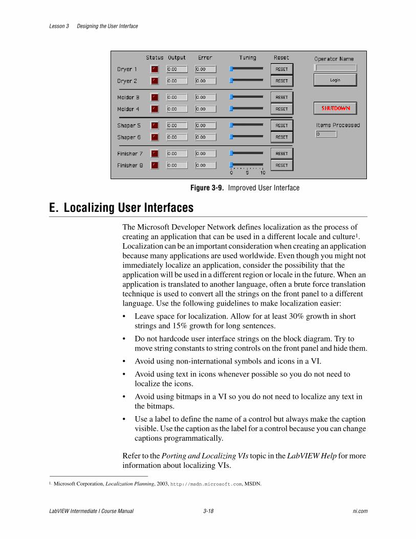
Lesson 3 Designing the User Interface
LabVIEW Intermediate I Course Manual 3-18 ni.com
Figure 3-9. Improved User Interface
E. Localizing User InterfacesThe Microsoft Developer Network defines localization as the process of creating an application that can be used in a different locale and culture1. Localization can be an important consideration when creating an application because many applications are used worldwide. Even though you might not immediately localize an application, consider the possibility that the application will be used in a different region or locale in the future. When an application is translated to another language, often a brute force translation technique is used to convert all the strings on the front panel to a different language. Use the following guidelines to make localization easier:
• Leave space for localization. Allow for at least 30% growth in short strings and 15% growth for long sentences.
• Do not hardcode user interface strings on the block diagram. Try to move string constants to string controls on the front panel and hide them.
• Avoid using non-international symbols and icons in a VI.
• Avoid using text in icons whenever possible so you do not need to localize the icons.
• Avoid using bitmaps in a VI so you do not need to localize any text in the bitmaps.
• Use a label to define the name of a control but always make the caption visible. Use the caption as the label for a control because you can change captions programmatically.
Refer to the Porting and Localizing VIs topic in the LabVIEW Help for more information about localizing VIs.
1. Microsoft Corporation, Localization Planning, 2003, http://msdn.microsoft.com, MSDN.

Lesson 3 Designing the User Interface
© National Instruments Corporation 3-19 LabVIEW Intermediate I Course Manual
Job AidUse the following checklist to ensure that your user interface follows good user interface design principles.
Front Panel Style Checklist❑ Give controls meaningful labels and captions.
❑ Ensure the background of control and indicator labels are transparent.
❑ Check for consistent placement of control labels.
❑ Use standard, consistent fonts—application, system, and dialog—throughout all front panels.
❑ Use Size to Text for all text for portability and add carriage returns if necessary.
❑ Use path controls instead of string controls to specify the location of files or directories.
❑ Write descriptions and create tip strips for controls and indicators, including array, cluster, and refnum elements.Remember that you might need to change the description if you copy the control.
❑ Group and arrange controls logically and attractively.
❑ Do not overlap controls with other controls, with their label, digital display, or other objects unless you want to achieve a special effect. Overlapped controls are much slower to draw and might flash.
❑ Use color logically, sparingly, and consistently, if at all.
❑ Provide a stop button if necessary. Do not use the Abort button to stop a VI. Hide the Abort button.
❑ Use ring controls and enumerated type controls where appropriate. If you are using a Boolean control for two options, consider using an enumerated type control instead to allow for future expansion of options.
❑ Use type definitions for common controls, especially for enumerated type controls and data structures.
❑ Make sure all the controls on the front panel are of the same style. For example, do not use both classic and modern controls on the same front panel.
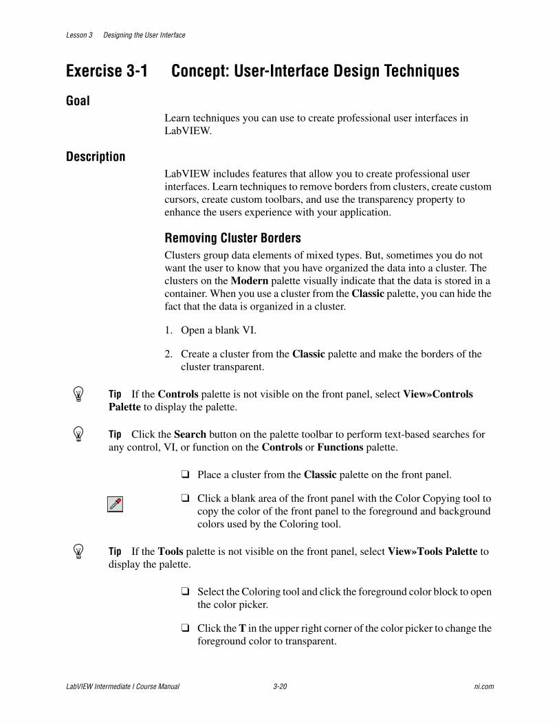
Lesson 3 Designing the User Interface
LabVIEW Intermediate I Course Manual 3-20 ni.com
Exercise 3-1 Concept: User-Interface Design Techniques
GoalLearn techniques you can use to create professional user interfaces in LabVIEW.
DescriptionLabVIEW includes features that allow you to create professional user interfaces. Learn techniques to remove borders from clusters, create custom cursors, create custom toolbars, and use the transparency property to enhance the users experience with your application.
Removing Cluster BordersClusters group data elements of mixed types. But, sometimes you do not want the user to know that you have organized the data into a cluster. The clusters on the Modern palette visually indicate that the data is stored in a container. When you use a cluster from the Classic palette, you can hide the fact that the data is organized in a cluster.
1. Open a blank VI.
2. Create a cluster from the Classic palette and make the borders of the cluster transparent.
Tip If the Controls palette is not visible on the front panel, select View»Controls Palette to display the palette.
Tip Click the Search button on the palette toolbar to perform text-based searches for any control, VI, or function on the Controls or Functions palette.
❑ Place a cluster from the Classic palette on the front panel.
❑ Click a blank area of the front panel with the Color Copying tool to copy the color of the front panel to the foreground and background colors used by the Coloring tool.
Tip If the Tools palette is not visible on the front panel, select View»Tools Palette to display the palette.
❑ Select the Coloring tool and click the foreground color block to open the color picker.
❑ Click the T in the upper right corner of the color picker to change the foreground color to transparent.
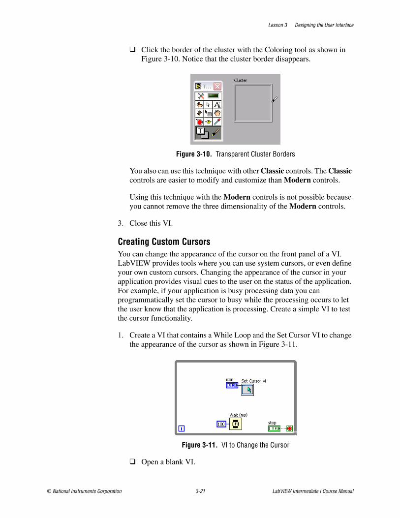
Lesson 3 Designing the User Interface
© National Instruments Corporation 3-21 LabVIEW Intermediate I Course Manual
❑ Click the border of the cluster with the Coloring tool as shown in Figure 3-10. Notice that the cluster border disappears.
Figure 3-10. Transparent Cluster Borders
You also can use this technique with other Classic controls. The Classic controls are easier to modify and customize than Modern controls.
Using this technique with the Modern controls is not possible because you cannot remove the three dimensionality of the Modern controls.
3. Close this VI.
Creating Custom CursorsYou can change the appearance of the cursor on the front panel of a VI. LabVIEW provides tools where you can use system cursors, or even define your own custom cursors. Changing the appearance of the cursor in your application provides visual cues to the user on the status of the application. For example, if your application is busy processing data you can programmatically set the cursor to busy while the processing occurs to let the user know that the application is processing. Create a simple VI to test the cursor functionality.
1. Create a VI that contains a While Loop and the Set Cursor VI to change the appearance of the cursor as shown in Figure 3-11.
Figure 3-11. VI to Change the Cursor
❑ Open a blank VI.
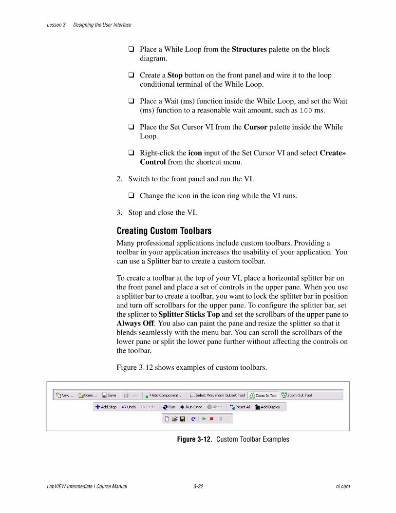
Lesson 3 Designing the User Interface
LabVIEW Intermediate I Course Manual 3-22 ni.com
❑ Place a While Loop from the Structures palette on the block diagram.
❑ Create a Stop button on the front panel and wire it to the loop conditional terminal of the While Loop.
❑ Place a Wait (ms) function inside the While Loop, and set the Wait (ms) function to a reasonable wait amount, such as 100 ms.
❑ Place the Set Cursor VI from the Cursor palette inside the While Loop.
❑ Right-click the icon input of the Set Cursor VI and select Create»Control from the shortcut menu.
2. Switch to the front panel and run the VI.
❑ Change the icon in the icon ring while the VI runs.
3. Stop and close the VI.
Creating Custom ToolbarsMany professional applications include custom toolbars. Providing a toolbar in your application increases the usability of your application. You can use a Splitter bar to create a custom toolbar.
To create a toolbar at the top of your VI, place a horizontal splitter bar on the front panel and place a set of controls in the upper pane. When you use a splitter bar to create a toolbar, you want to lock the splitter bar in position and turn off scrollbars for the upper pane. To configure the splitter bar, set the splitter to Splitter Sticks Top and set the scrollbars of the upper pane to Always Off. You also can paint the pane and resize the splitter so that it blends seamlessly with the menu bar. You can scroll the scrollbars of the lower pane or split the lower pane further without affecting the controls on the toolbar.
Figure 3-12 shows examples of custom toolbars.
Figure 3-12. Custom Toolbar Examples
Lesson 3 Designing the User Interface
© National Instruments Corporation 3-23 LabVIEW Intermediate I Course Manual
1. Add a horizontal splitter bar to the front panel.
❑ Open a blank VI.
❑ Place a Horizontal Splitter Bar on the front panel. Position the splitter bar near the top of the VI. Leave enough space to place controls inside the pane the splitter bar creates.
2. Turn off the horizontal and vertical scrollbars of the splitter bar.
❑ Right-click the splitter bar and select Always Off from the Upper Pane»Horizontal Scrollbar and Upper Pane»Vertical Scrollbar shortcut menus.
3. Change the style of the splitter bar to system.
❑ Right-click the splitter bar and select Splitter Style»System from the shortcut menu.
4. Add controls to the pane above the splitter bar.
❑ Place the toolbar controls located in the C:\Exercises\LabVIEW Intermediate I\User Interface Design Techniques\Toolbar Controls directory in the upper pane created by the splitter bar.
5. Rearrange the controls and color the splitter bar to look like a toolbar.
❑ Hide the labels on the controls.
❑ Use the Align Objects and Distribute Objects buttons on the toolbar to align the controls.
❑ Color the background of the pane to blend the controls into the panel.
Click the background color block of the Coloring tool to open the color picker.
Click the More Colors button in the bottom right corner of the color picker to open the Color dialog box.
Enter the following values and click the OK button to set the background color:
– Red: 231
– Green: 223
– Blue: 231

Lesson 3 Designing the User Interface
LabVIEW Intermediate I Course Manual 3-24 ni.com
6. Lock the splitter bar so that the user cannot move it.
❑ Right-click the splitter bar and make sure Locked is checked in the shortcut menu.
7. Close the VI.
Creating Transparent ControlsUsing transparency with controls can add a professional touch to the user interface. Some applications use an indicator to display the status of an operation to the user. Often, HMI systems require the user to click the indicator to respond to the message. Modify an existing VI that uses a Tank indicator to display fluid levels. To obtain the current value of the Tank, the user must click the Tank. To modify this VI, place a Boolean control on top of the Tank indicator and change the colors of the Boolean control to transparent.
1. Add a Boolean button to the existing Tank Value VI.
❑ Open Tank Value.vi located in the C:\Exercises\LabVIEW Intermediate I\User Interface Design Techniques directory.
❑ Place a Flat Square button from the Classic palette on top of the Tank, and resize the control to fit completely on top of the Tank.
❑ Change the Flat Square button to a control.
2. Modify the button to make it transparent.
❑ Change the True and False color of the button to transparent by using the Coloring tool.
❑ Click the button with the Operating tool to verify that the button is transparent whether it is True or False.
3. Modify the block diagram to use a Case structure inside the While Loop to cause the Tank Value indicator to update only when the button on top of the tank is True, as shown in Figure 3-13.
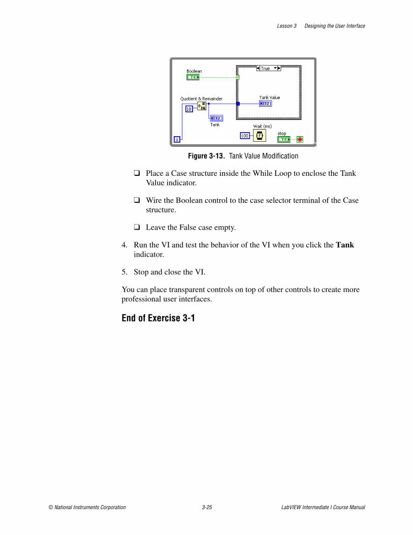
Lesson 3 Designing the User Interface
© National Instruments Corporation 3-25 LabVIEW Intermediate I Course Manual
Figure 3-13. Tank Value Modification
❑ Place a Case structure inside the While Loop to enclose the Tank Value indicator.
❑ Wire the Boolean control to the case selector terminal of the Case structure.
❑ Leave the False case empty.
4. Run the VI and test the behavior of the VI when you click the Tank indicator.
5. Stop and close the VI.
You can place transparent controls on top of other controls to create more professional user interfaces.
End of Exercise 3-1
Lesson 3 Designing the User Interface
LabVIEW Intermediate I Course Manual 3-26 ni.com
Summary• Design a well-organized and easy to use user interface.
• Consider both design and layout issues when developing a user interface front panel.
• Use the front panel style checklist to ensure that your user interface follows good user interface design principles.

Lesson 3 Designing the User Interface
© National Instruments Corporation 3-27 LabVIEW Intermediate I Course Manual
Notes

Lesson 3 Designing the User Interface
LabVIEW Intermediate I Course Manual 3-28 ni.com
Notes
© National Instruments Corporation 4-1 LabVIEW Intermediate I Course Manual
4Designing the Project
Producing a software design is the next step in developing an application. Proper design of an application ensures that you develop an application that is scalable, readable, and maintainable. Proper design also ensures that the user interface is intuitive and easy to use. At the end of this lesson, you design a software implementation for the software project that you analyzed.
TopicsA. Design Patterns
B. Event-Based Design Patterns
C. Advanced Event-Based Design Patterns
D. Creating a Hierarchical Architecture
E. Using the LabVIEW Project and Project Libraries
F. Choosing Data Types
G. Information Hiding
H. Designing Error Handling Strategies
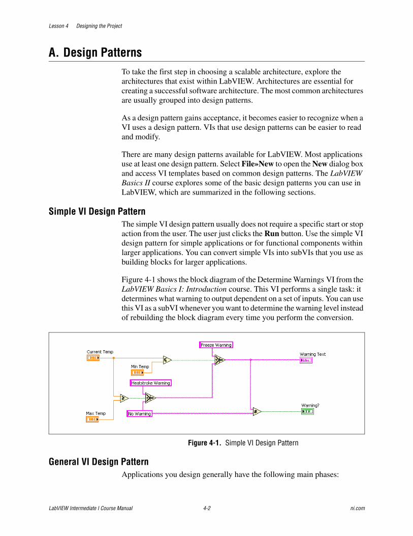
Lesson 4 Designing the Project
LabVIEW Intermediate I Course Manual 4-2 ni.com
A. Design PatternsTo take the first step in choosing a scalable architecture, explore the architectures that exist within LabVIEW. Architectures are essential for creating a successful software architecture. The most common architectures are usually grouped into design patterns.
As a design pattern gains acceptance, it becomes easier to recognize when a VI uses a design pattern. VIs that use design patterns can be easier to read and modify.
There are many design patterns available for LabVIEW. Most applications use at least one design pattern. Select File»New to open the New dialog box and access VI templates based on common design patterns. The LabVIEW Basics II course explores some of the basic design patterns you can use in LabVIEW, which are summarized in the following sections.
Simple VI Design PatternThe simple VI design pattern usually does not require a specific start or stop action from the user. The user just clicks the Run button. Use the simple VI design pattern for simple applications or for functional components within larger applications. You can convert simple VIs into subVIs that you use as building blocks for larger applications.
Figure 4-1 shows the block diagram of the Determine Warnings VI from the LabVIEW Basics I: Introduction course. This VI performs a single task: it determines what warning to output dependent on a set of inputs. You can use this VI as a subVI whenever you want to determine the warning level instead of rebuilding the block diagram every time you perform the conversion.
Figure 4-1. Simple VI Design Pattern
General VI Design PatternApplications you design generally have the following main phases:
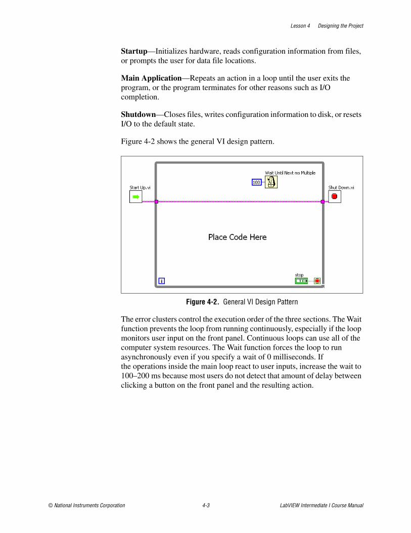
Lesson 4 Designing the Project
© National Instruments Corporation 4-3 LabVIEW Intermediate I Course Manual
Startup—Initializes hardware, reads configuration information from files, or prompts the user for data file locations.
Main Application—Repeats an action in a loop until the user exits the program, or the program terminates for other reasons such as I/O completion.
Shutdown—Closes files, writes configuration information to disk, or resets I/O to the default state.
Figure 4-2 shows the general VI design pattern.
Figure 4-2. General VI Design Pattern
The error clusters control the execution order of the three sections. The Wait function prevents the loop from running continuously, especially if the loop monitors user input on the front panel. Continuous loops can use all of the computer system resources. The Wait function forces the loop to run asynchronously even if you specify a wait of 0 milliseconds. If the operations inside the main loop react to user inputs, increase the wait to 100–200 ms because most users do not detect that amount of delay between clicking a button on the front panel and the resulting action.
Lesson 4 Designing the Project
LabVIEW Intermediate I Course Manual 4-4 ni.com
State Machine Design PatternThe state machine design pattern is one of the most recognized and useful design patterns for LabVIEW. Use the state machine design pattern to implement any algorithm that can be explicitly described by a state diagram or flowchart, such as a diagnostic routine or a process monitor.
Use state machines in applications that contain distinguishable states, such as a user interface or a process test. User input or in-state calculation determines which state to go to next. An application based on the state machine design pattern often has an initialization state, a default state, and a shutdown state. The actions performed in the default state can depend on previous and current inputs and states. The shutdown state performs clean up actions.
In a user interface state machine, different user actions send the user interface into different processing segments. Each processing segment acts as a state in the state machine and can lead to another segment or wait for another user action.
For a process test state machine, each state represents a segment of the process. The test result of a state determines the next state. State transitions can occur continually, providing an in-depth analysis of a process.
State Machine InfrastructureA state machine in LabVIEW consists of the following block diagram components:
• While Loop—Continually executes the various states
• Case Structure—Contains a case for each state and the code to execute for each state
• Shift Register—Contains state transition information
• State Functionality Code—Implements the function of the state
• Transition Code—Determines the next state in the sequence
Figure 4-3 shows the basic structure of a state machine implemented in LabVIEW for a temperature data acquisition system.

Lesson 4 Designing the Project
© National Instruments Corporation 4-5 LabVIEW Intermediate I Course Manual
Figure 4-3. Basic Infrastructure of a LabVIEW State Machine
The While Loop implements the flow of the state transition diagram. Cases in the Case structure represent individual states. A shift register on the While Loop keeps track of the current state and communicates the current state to the Case structure input.
Queued Message Handler Design PatternUse the queued message handler to implement code for a user interface. The queued message handler queues messages and then handles messages one-by-one in the order that they exist in the queue. Each subdiagram in the queued message handler represents a handling routine.
The queued message handler design pattern consists of a While Loop, an internal Case structure, and a shift register on the While Loop that holds the queued messages, as shown in Figure 4-4.
1 While Loop 2 Shift Register 3 Case Structure
1
2
3
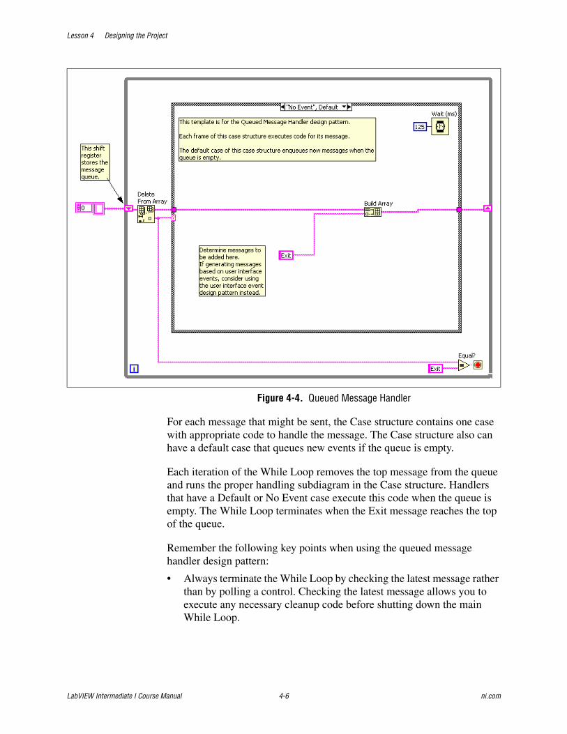
Lesson 4 Designing the Project
LabVIEW Intermediate I Course Manual 4-6 ni.com
Figure 4-4. Queued Message Handler
For each message that might be sent, the Case structure contains one case with appropriate code to handle the message. The Case structure also can have a default case that queues new events if the queue is empty.
Each iteration of the While Loop removes the top message from the queue and runs the proper handling subdiagram in the Case structure. Handlers that have a Default or No Event case execute this code when the queue is empty. The While Loop terminates when the Exit message reaches the top of the queue.
Remember the following key points when using the queued message handler design pattern:
• Always terminate the While Loop by checking the latest message rather than by polling a control. Checking the latest message allows you to execute any necessary cleanup code before shutting down the main While Loop.

Lesson 4 Designing the Project
© National Instruments Corporation 4-7 LabVIEW Intermediate I Course Manual
• Although you can generate new messages inside the handler code for a message, it is possible to generate an infinite cascade of messages, which would effectively hang the user interface. A good guideline is to require that messages generated by handler code never generate new messages of their own.
Parallel Loop Design PatternFor applications that require the program to respond to and run several tasks concurrently, you can assign a different loop to each task in the main section of the application. For example, you might have a different loop for each button on the front panel and for every other kind of task, such as a menu selection, I/O trigger, and so on. Figure 4-5 shows the parallel loop VI design pattern.
Figure 4-5. Parallel Loop Design Pattern
Use the parallel loop design pattern for simple menu VIs where you expect a user to select from one of several buttons that perform different actions. You can handle multiple, simultaneous, independent processes and responding to one action does not prevent the VI from responding to another action. For example, if a user clicks a button that displays a dialog box, parallel loops can continue to respond to I/O tasks.
The parallel loop VI design pattern requires you to coordinate and communicate among different loops. You cannot use wires to pass data between loops because doing so prevents the loops from running in parallel. Instead, you must use a messaging technique for passing information among

Lesson 4 Designing the Project
LabVIEW Intermediate I Course Manual 4-8 ni.com
processes. This can lead to race conditions where multiple tasks attempt to read and modify the same data simultaneously resulting in inconsistent behavior that is difficult to debug.
Master/Slave Design PatternUse the master/slave design pattern to run two or more processes simultaneously and pass messages among the processes. The master/slave pattern consists of multiple parallel loops. Each of the loops may execute tasks at different rates. One loop acts as the master, and the other loops act as slaves. The master loop controls all the slave loops and communicates with them using messaging architectures as shown in Figure 4-6.
Figure 4-6. Master/Slave Design Pattern
Use the master/slave pattern to respond to user interface controls while simultaneously collecting data. VIs that involve control also benefit from the use of master/slave design patterns.
The master/slave design pattern separates the data flow of the block diagram into independent processes and uses globally available shared data to synchronize data transfer among loops. However, using a global variable to transfer data among the master and slave loops breaks the LabVIEW dataflow paradigm, allows for race conditions, and incurs more overhead than passing the data by wire.
Use a notifier to pass data from the master to the slave to remove any issues with race conditions. Using notifiers improves synchronization because the master and slave are timed when data is available. Figure 4-7 shows the master/slave design pattern using notifiers.

Lesson 4 Designing the Project
© National Instruments Corporation 4-9 LabVIEW Intermediate I Course Manual
Figure 4-7. Master/Slave Design Pattern Using Notifiers
Using notifiers in the master/slave design pattern results in the following benefits:
• Both loops are synchronized to the master loop. The slave loop only executes when the master loop sends a notification.
• You can use notifiers to create globally available data. Thus, it is possible to send data with a notification.
• Using notifiers creates efficient code. There is no need to use polling to determine when data is available from the master loop.
With a master/slave design pattern, make sure that no two While Loops write to the same shared data.
The slave loop should not take too long to respond to the master. If the slave is processing a signal from the master and the master sends more than one message to the slave, the slave only receives the latest message. Use a master/slave design pattern only if you are certain that each slave task executes faster than the master loop.
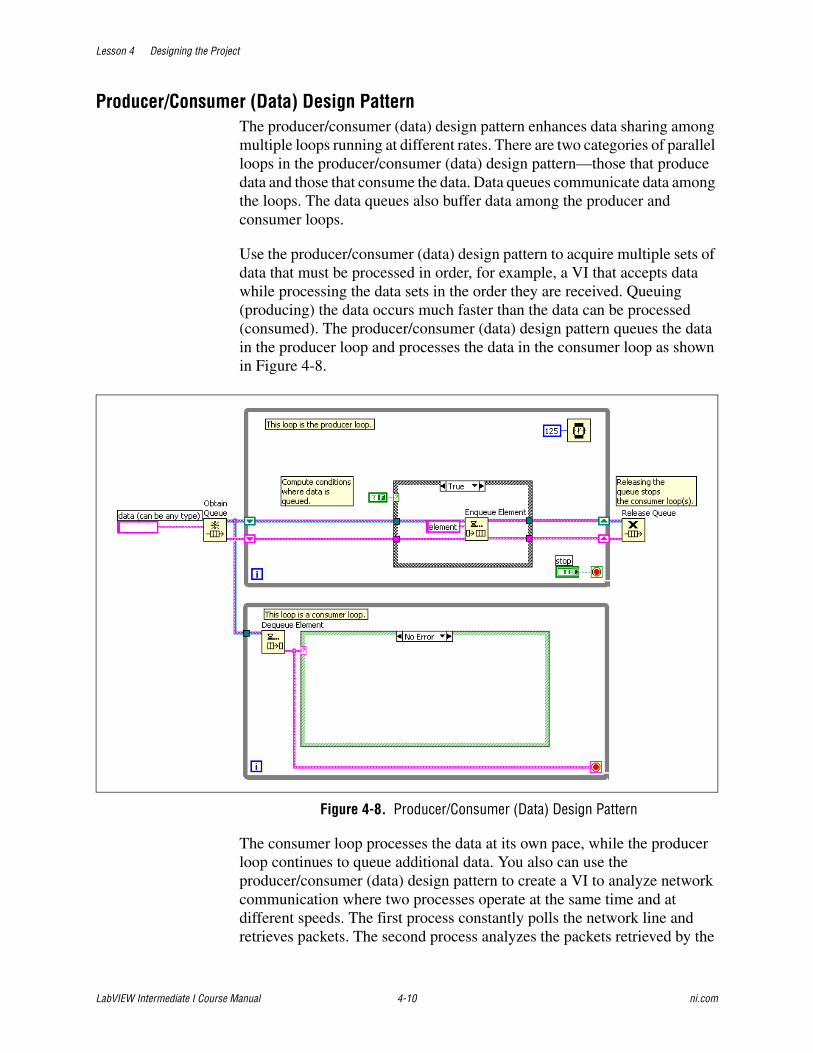
Lesson 4 Designing the Project
LabVIEW Intermediate I Course Manual 4-10 ni.com
Producer/Consumer (Data) Design PatternThe producer/consumer (data) design pattern enhances data sharing among multiple loops running at different rates. There are two categories of parallel loops in the producer/consumer (data) design pattern—those that produce data and those that consume the data. Data queues communicate data among the loops. The data queues also buffer data among the producer and consumer loops.
Use the producer/consumer (data) design pattern to acquire multiple sets of data that must be processed in order, for example, a VI that accepts data while processing the data sets in the order they are received. Queuing (producing) the data occurs much faster than the data can be processed (consumed). The producer/consumer (data) design pattern queues the data in the producer loop and processes the data in the consumer loop as shown in Figure 4-8.
Figure 4-8. Producer/Consumer (Data) Design Pattern
The consumer loop processes the data at its own pace, while the producer loop continues to queue additional data. You also can use the producer/consumer (data) design pattern to create a VI to analyze network communication where two processes operate at the same time and at different speeds. The first process constantly polls the network line and retrieves packets. The second process analyzes the packets retrieved by the
Lesson 4 Designing the Project
© National Instruments Corporation 4-11 LabVIEW Intermediate I Course Manual
first process. The first process acts as the producer because it supplies data to the second process, which acts as the consumer. The parallel producer and consumer loops handle the retrieval and analysis of data off the network, and the queued communication between the two loops allows buffering of the network packets retrieved.
Lesson 4 Designing the Project
LabVIEW Intermediate I Course Manual 4-12 ni.com
Exercise 4-1 Concept: Experiment with Design Patterns
GoalObserve the functionality and design of standard LabVIEW design patterns.
DescriptionExplore the design pattern VI templates that ship with LabVIEW and observe how they operate. You can use the design pattern VI templates that are built into LabVIEW as the basis for the underlying architecture of VIs you create.
1. Select File»New to open the New dialog box.
2. In the Create New section, expand the VI»From Template»Frameworks»Design Patterns tree.
3. Select the Standard State Machine design pattern from the tree and click the OK button to open the template.
4. Open the block diagram, turn execution highlighting on, and run the VI.
Notice how the design pattern handles the following items:
❑ State transitions
❑ Data flow
5. Close the design pattern. Do not save changes.
6. Repeat steps 1 through 5 to observe the operation of the following design pattern VI templates:
❑ Master/Slave Design Pattern
❑ Queued Message Handler Design Pattern
❑ Producer/Consumer Design Pattern (Data)
In particular, observe the data flow with the Master/Slave Design Pattern, and the Producer/Consumer Design Pattern (Data). Also, compare and contrast the differences between the Master/Slave Design Pattern and the Producer/Consumer Design Pattern (Data). As you run these templates, notice how each template implements a message passing mechanism.
End of Exercise 4-1
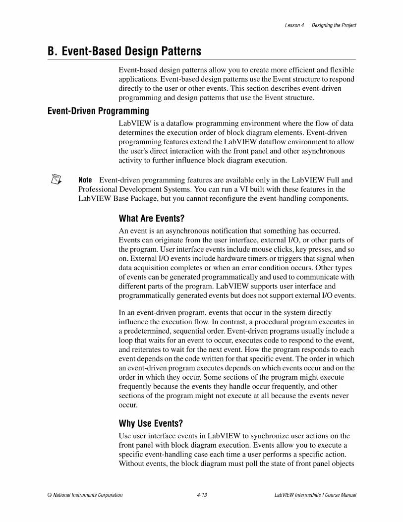
Lesson 4 Designing the Project
© National Instruments Corporation 4-13 LabVIEW Intermediate I Course Manual
B. Event-Based Design PatternsEvent-based design patterns allow you to create more efficient and flexible applications. Event-based design patterns use the Event structure to respond directly to the user or other events. This section describes event-driven programming and design patterns that use the Event structure.
Event-Driven ProgrammingLabVIEW is a dataflow programming environment where the flow of data determines the execution order of block diagram elements. Event-driven programming features extend the LabVIEW dataflow environment to allow the user's direct interaction with the front panel and other asynchronous activity to further influence block diagram execution.
Note Event-driven programming features are available only in the LabVIEW Full and Professional Development Systems. You can run a VI built with these features in the LabVIEW Base Package, but you cannot reconfigure the event-handling components.
What Are Events?An event is an asynchronous notification that something has occurred. Events can originate from the user interface, external I/O, or other parts of the program. User interface events include mouse clicks, key presses, and so on. External I/O events include hardware timers or triggers that signal when data acquisition completes or when an error condition occurs. Other types of events can be generated programmatically and used to communicate with different parts of the program. LabVIEW supports user interface and programmatically generated events but does not support external I/O events.
In an event-driven program, events that occur in the system directly influence the execution flow. In contrast, a procedural program executes in a predetermined, sequential order. Event-driven programs usually include a loop that waits for an event to occur, executes code to respond to the event, and reiterates to wait for the next event. How the program responds to each event depends on the code written for that specific event. The order in which an event-driven program executes depends on which events occur and on the order in which they occur. Some sections of the program might execute frequently because the events they handle occur frequently, and other sections of the program might not execute at all because the events never occur.
Why Use Events?Use user interface events in LabVIEW to synchronize user actions on the front panel with block diagram execution. Events allow you to execute a specific event-handling case each time a user performs a specific action. Without events, the block diagram must poll the state of front panel objects
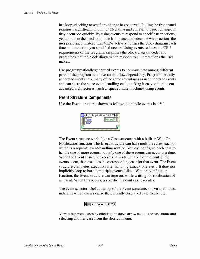
Lesson 4 Designing the Project
LabVIEW Intermediate I Course Manual 4-14 ni.com
in a loop, checking to see if any change has occurred. Polling the front panel requires a significant amount of CPU time and can fail to detect changes if they occur too quickly. By using events to respond to specific user actions, you eliminate the need to poll the front panel to determine which actions the user performed. Instead, LabVIEW actively notifies the block diagram each time an interaction you specified occurs. Using events reduces the CPU requirements of the program, simplifies the block diagram code, and guarantees that the block diagram can respond to all interactions the user makes.
Use programmatically generated events to communicate among different parts of the program that have no dataflow dependency. Programmatically generated events have many of the same advantages as user interface events and can share the same event handling code, making it easy to implement advanced architectures, such as queued state machines using events.
Event Structure ComponentsUse the Event structure, shown as follows, to handle events in a VI.
The Event structure works like a Case structure with a built-in Wait On Notification function. The Event structure can have multiple cases, each of which is a separate event-handling routine. You can configure each case to handle one or more events, but only one of these events can occur at a time. When the Event structure executes, it waits until one of the configured events occur, then executes the corresponding case for that event. The Event structure completes execution after handling exactly one event. It does not implicitly loop to handle multiple events. Like a Wait on Notification function, the Event structure can time out while waiting for notification of an event. When this occurs, a specific Timeout case executes.
The event selector label at the top of the Event structure, shown as follows, indicates which events cause the currently displayed case to execute.
View other event cases by clicking the down arrow next to the case name and selecting another case from the shortcut menu.
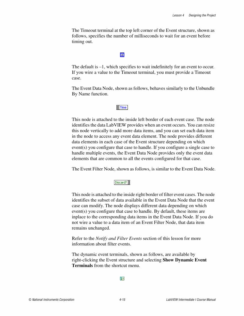
Lesson 4 Designing the Project
© National Instruments Corporation 4-15 LabVIEW Intermediate I Course Manual
The Timeout terminal at the top left corner of the Event structure, shown as follows, specifies the number of milliseconds to wait for an event before timing out.
The default is –1, which specifies to wait indefinitely for an event to occur. If you wire a value to the Timeout terminal, you must provide a Timeout case.
The Event Data Node, shown as follows, behaves similarly to the Unbundle By Name function.
This node is attached to the inside left border of each event case. The node identifies the data LabVIEW provides when an event occurs. You can resize this node vertically to add more data items, and you can set each data item in the node to access any event data element. The node provides different data elements in each case of the Event structure depending on which event(s) you configure that case to handle. If you configure a single case to handle multiple events, the Event Data Node provides only the event data elements that are common to all the events configured for that case.
The Event Filter Node, shown as follows, is similar to the Event Data Node.
This node is attached to the inside right border of filter event cases. The node identifies the subset of data available in the Event Data Node that the event case can modify. The node displays different data depending on which event(s) you configure that case to handle. By default, these items are inplace to the corresponding data items in the Event Data Node. If you do not wire a value to a data item of an Event Filter Node, that data item remains unchanged.
Refer to the Notify and Filter Events section of this lesson for more information about filter events.
The dynamic event terminals, shown as follows, are available by right-clicking the Event structure and selecting Show Dynamic Event Terminals from the shortcut menu.

Lesson 4 Designing the Project
LabVIEW Intermediate I Course Manual 4-16 ni.com
These terminals are used only for dynamic event registration.
Refer to the Dynamic Event Registration and the Modifying Registration Dynamically topics of the LabVIEW Help for more information about using these terminals.
Note Like a Case structure, the Event structure supports tunnels. However, by default you do not have to wire Event structure output tunnels in every case. All unwired tunnels use the default value for the tunnel data type. Right-click a tunnel and deselect Use Default If Unwired from the shortcut menu to revert to the default Case structure behavior where tunnels must be wired in all cases.
Refer to the LabVIEW Help for information about the default values for data types.
Notify and Filter EventsThere are two types of user interface events—notify and filter.
Notify events are an indication that a user action has already occurred, such as when the user has changed the value of a control. Use notify events to respond to an event after it has occurred and LabVIEW has processed it. You can configure any number of Event structures to respond to the same notify event on a specific object. When the event occurs, LabVIEW sends a copy of the event to each Event structure configured to handle the event in parallel.
Filter events inform you that the user has performed an action before LabVIEW processes it, which allows you to customize how the program responds to interactions with the user interface. Use filter events to participate in the handling of the event, possibly overriding the default behavior for the event. In an Event structure case for a filter event, you can validate or change the event data before LabVIEW finishes processing it, or you can discard the event entirely to prevent the change from affecting the VI. For example, you can configure an Event structure to discard the Panel Close? event, preventing the user from interactively closing the front panel of the VI. Filter events have names that end with a question mark, such as Panel Close?, to help you distinguish them from notify events. Most filter events have an associated notify event of the same name, but without the question mark, which LabVIEW generates after the filter event if no event case discarded the event.
As with notify events, you can configure any number of Event structures to respond to the same filter event on a specific object. However, LabVIEW sends filter events sequentially to each Event structure configured for the event. The order in which LabVIEW sends the event to each Event structure depends on the order in which the events were registered. Each Event

Lesson 4 Designing the Project
© National Instruments Corporation 4-17 LabVIEW Intermediate I Course Manual
structure must complete its event case for the event before LabVIEW can notify the next Event structure. If an Event structure case changes any of the event data, LabVIEW passes the changed data to subsequent Event structures in the chain. If an Event structure in the chain discards the event, LabVIEW does not pass the event to any Event structures remaining in the chain. LabVIEW completes processing the user action which triggered the event only after all configured Event structures handle the event without discarding it.
Note National Instruments recommends you use filter events only when you want to take part in the handling of the user action, either by discarding the event or by modifying the event data. If you only want to know that the user performed a particular action, use notify events.
Event structure cases that handle filter events have an Event Filter Node. You can change the event data by wiring new values to these terminals. If you do not wire a data item, that item remains unchanged. You can completely discard an event by wiring a TRUE value to the Discard? terminal.
Note A single case in the Event structure cannot handle both notify and filter events. A case can handle multiple notify events but can handle multiple filter events only if the event data items are identical for all events.
Refer to the Using Events in LabVIEW section of this lesson for more information about event registration.
Tip In the Edit Events dialog box, notify events are signified by a green arrow, and filter events are signified by a red arrow.
Using Events in LabVIEWLabVIEW can generate many different events. To avoid generating unwanted events, use event registration to specify which events you want LabVIEW to notify you about. LabVIEW supports two models for event registration— static and dynamic.
Static registration allows you to specify which events on the front panel of a VI you want to handle in each Event structure case on the block diagram of that VI. LabVIEW registers these events automatically when the VI runs, so the Event structure begins waiting for events as soon as the VI begins running. Each event is associated with a control on the front panel of the VI, the front panel window of the VI as a whole, or the LabVIEW application. You cannot statically configure an Event structure to handle events for the front panel of a different VI. Configuration is static because you cannot change at run time which events the Event structure handles.
Lesson 4 Designing the Project
LabVIEW Intermediate I Course Manual 4-18 ni.com
Dynamic event registration avoids the limitations of static registration by integrating event registration with the VI Server, which allows you to use Application, VI, and control references to specify at run time the objects for which you want to generate events. Dynamic registration provides more flexibility in controlling what events LabVIEW generates and when it generates them. However, dynamic registration is more complex than static registration because it requires using VI Server references with block diagram functions to explicitly register and unregister for events rather than handling registration automatically using the information you configured in the Event structure.
Note In general, LabVIEW generates user interface events only as a result of direct user interaction with the active front panel. LabVIEW does not generate events, such as Value Change, when you use shared variables, global variables, local variables, DataSocket, and so on. However, you can use the Value (Signaling) property to generate a Value Change event programmatically. In many cases, you can use programmatically generated events instead of queues and notifiers.
The event data provided by a LabVIEW event always include a time stamp, an enumeration that indicates which event occurred, and a VI Server reference to the object that triggered the event. The time stamp is a millisecond counter you can use to compute the time elapsed between two events or to determine the order of occurrence. The reference to the object that generated the event is strictly typed to the VI Server class of that object. Events are grouped into classes according to what type of object generates the event, such as Application, VI, or Control. If a single case handles multiple events for objects of different VI Server classes, the reference type is the common parent class of all objects. For example, if you configure a single case in the Event structure to handle events for a numeric control and a color ramp control, the type of the control reference of the event source is Numeric because the numeric and color ramp controls are in the Numeric class.
Note If you register for the same event on both the VI and Control class, LabVIEW generates the VI event first. LabVIEW generates Control events for container objects, such as clusters, before it generates events for the objects they contain. If the Event structure case for a VI event or for a Control event on a container object discards the event, LabVIEW does not generate further events.
Each Event structure and Register For Events function on the block diagram owns a queue that LabVIEW uses to store events. When an event occurs, LabVIEW places a copy of the event into each queue registered for that event. An Event structure handles all events in its queue and the events in the queues of any Register For Events functions that you wired to the dynamic event terminals of the Event structure. LabVIEW uses these queues

Lesson 4 Designing the Project
© National Instruments Corporation 4-19 LabVIEW Intermediate I Course Manual
to ensure that events are reliably delivered to each registered Event structure in the order the events occur.
By default, when an event enters a queue, LabVIEW locks the front panel that contains the object that generated that event. LabVIEW keeps the front panel locked until all Event structures finish handling the event. While the front panel is locked, LabVIEW does not process front panel activity but places those interactions in a buffer and handles them when the front panel is unlocked. Front panel locking does not affect certain actions, such as moving the window, interacting with the scroll bars, and clicking the Abort button. You can disable front panel locking for notify events by removing the checkmark from the option in the Edit Events dialog box. Front panel locking must be enabled for filter events to ensure the internal state of LabVIEW is not altered before it has an opportunity to completely process the pending event.
LabVIEW can generate events even when no Event structure is waiting to handle them. Because the Event structure handles only one event each time it executes, place the Event structure in a While Loop to ensure that an Event structure can handle all events that occur.
Caution If no Event structure executes to handle an event and front panel locking is enabled, the user interface of the VI becomes unresponsive. If this occurs, click the Abort button to stop the VI. You can disable panel locking by right-clicking the Event structure and removing the checkmark from the Lock front panel until the event case for this event completes checkbox in the Edit Events dialog box. You cannot turn off front panel locking for filter events.
Refer to the LabVIEW Help for more information about caveats and recommendations when using events in LabVIEW. Refer to the LabVIEW Help for information about available events.
Static Event RegistrationStatic event registration is available only for user interface events. Use the Edit Events dialog box to configure an Event structure to handle a statically registered event. Select the event source, which can be the application, the VI, or an individual control. Select a specific event the event source can generate, such as Panel Resize, Value Change, and so on. Edit the case to handle the event data according to the application requirements.
LabVIEW statically registers events automatically and transparently when you run a VI that contains an Event structure. LabVIEW generates events for a VI only while that VI is running or when another running VI calls the VI as a subVI.
Lesson 4 Designing the Project
LabVIEW Intermediate I Course Manual 4-20 ni.com
When you run a VI, LabVIEW sets that top-level VI and the hierarchy of subVIs the VI calls on its block diagram to an execution state called reserved. You cannot edit a VI or click the Run button while the VI is in the reserved state because the VI can be called as a subVI at any time while its parent VI runs. When LabVIEW sets a VI to the reserved state, it automatically registers the events you statically configured in all Event structures on the block diagram of that VI. When the top-level VI finishes running, LabVIEW sets it and its subVI hierarchy to the idle execution state and automatically unregisters the events.
Refer to the labview\examples\general\uievents.llb for examples of using static event registration.
Configuring EventsBefore you configure events for the Event structure to handle, refer to the LabVIEW Help for more information about caveats and recommendations when using events in LabVIEW.
Complete the following steps to configure an Event structure case to handle an event.
1. (Optional) If you want to configure the Event structure to handle a user event, a Boolean control, or a user interface event that is generated based on a reference to an application, VI, or control, you must first dynamically register that event. Refer to the Dynamic Event Registration topic of the LabVIEW Help for more information about using dynamic events.
2. Right-click the border of the Event structure and select Edit Events Handled by This Case from the shortcut menu to display the Edit Events dialog box to edit the current case. You also can select Add Event Case from the shortcut menu to create a new case.
3. Specify an event source in the Event Sources section.
4. Select the event you want to configure for the event source, such as Key Down, Timeout, or Value Change from the Events list. When you select a dynamic event source from the Event Sources list, the Events list displays that event. This is the same event you selected when you registered the event. If you have registered for events dynamically and wired event reg refnum out to the dynamic event terminal, the sources appear in the Dynamic section.
5. If you want to add additional events for the current case to handle, click the + button and repeat steps 3 and 4 to specify each additional event. The Event Specifiers section at the top of the dialog box lists all the events for the case to handle. When you click an item in this list, the Event Sources section updates to highlight the event source you

Lesson 4 Designing the Project
© National Instruments Corporation 4-21 LabVIEW Intermediate I Course Manual
selected. You can repeat steps 3 and 4 to redefine each event or click the X button to remove the selected event.
6. Click the OK button to save the configuration and close the dialog box.
7. Repeat steps 1 through 6 for each event case you want to configure.
Refer to the following VIs for examples of using events:
labview\examples\general\dynamicevents.llb
labview\examples\general\uievents.llb for examples of using events.
Event ExampleFigure 4-9 shows an Event structure configured with the Menu Selection (User) event. This VI uses the Event structure to capture menu selections made using the user-defined menu named sample.rtm. The ItemTag returns the menu item that was selected and the MenuRef returns the refnum to the menubar. This information is passed to the Get Menu Item Info function. Refer to examples\general\uievents.llb for more examples of using events.
Figure 4-9. Menu Selection (User) Event
Note If you use the Get Menu Selection function with an Event structure configured to handle the same menu item, the Event structure takes precedence, and LabVIEW ignores the Get Menu Selection function. In any given VI, use the Event structure or the Get Menu Selection function to handle menu events, not both.
Lesson 4 Designing the Project
LabVIEW Intermediate I Course Manual 4-22 ni.com
Exercise 4-2 Concept: Experiment with Event Structures
GoalExperiment with the operation of the Event structure in a VI.
DescriptionUse and modify a VI that contains an Event structure.
1. Open the NI Example Finder.
❑ Select Help»Find Examples.
2. Open the New Event Handler VI example.
❑ Navigate to Building User Interfaces»Acquiring User Input»General and double-click New Event Handler.vi.
3. Enable execution highlighting on the block diagram.
4. Run the VI.
5. Observe the operation of the VI when you click the buttons on the front panel.
6. Stop the VI.
7. Modify the VI to respond to a Value Change event with a new control on the front panel.
❑ Switch to the front panel of the VI.
❑ Create a copy of a Boolean button on the front panel.
❑ Change the button text and label of the button to New Button.
❑ Right-click the new button and verify that the Mechanical Action is set to Latch When Released.
❑ Switch to the block diagram of the VI.
❑ Right-click the border of the Event structure and select Add Event Case from the shortcut menu to open the Edit Events dialog box.
❑ Select New Button in the Event Sources section and select Value Change in the Events section as shown in Figure 4-10.

Lesson 4 Designing the Project
© National Instruments Corporation 4-23 LabVIEW Intermediate I Course Manual
Figure 4-10. New Button Value Change Event
❑ Click OK to create the new Event structure case.
❑ Place a One Button Dialog function in the New Button event case and wire a string constant to the message input. Set the string constant to New Event Case.
❑ Wire the Time Waveform data through the case.
❑ Wire a False constant to the Boolean tunnel.
❑ Run the VI and click New Button. A dialog box should open and display the New Event Case message.
8. Modify the Event structure to add a Filter Event to discard the Panel Close event.
❑ Right-click the Event structure and select Add Event Case from the shortcut menu to open the Edit Events dialog box.
❑ Select <This VI> in the Event Sources section.

Lesson 4 Designing the Project
LabVIEW Intermediate I Course Manual 4-24 ni.com
❑ Select Panel Close? from the Events list and click the OK button.
❑ Wire a True constant to the Discard? Event Filter Node in the Panel Close? case.
❑ Wire the Time Waveform data through the case.
❑ Wire a False constant to the Boolean tunnel.
9. Run the VI.
10. Attempt to close the VI by closing the front panel.
11. Click the STOP button to stop the VI.
12. Open the NI Example Finder.
13. Open the Old Event Handler VI example.
❑ Navigate to Building User Interfaces»Acquiring User Input»General and double-click Old Event Handler.vi.
14. Enable execution highlighting on the block diagram.
15. Run the VI.
16. Observe the operation of the Old Event Handler VI and compare and contrast the operation with the New Event Handler VI.
17. Close all VIs without saving changes.
End of Exercise 4-2
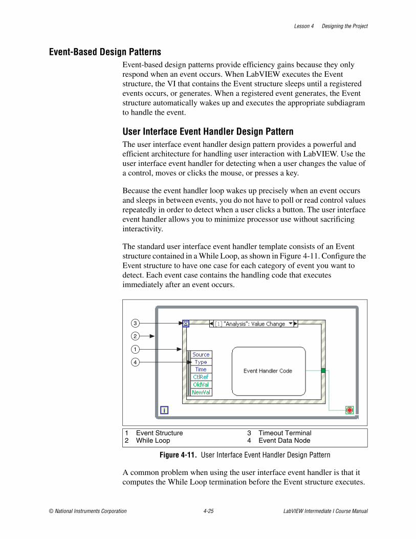
Lesson 4 Designing the Project
© National Instruments Corporation 4-25 LabVIEW Intermediate I Course Manual
Event-Based Design PatternsEvent-based design patterns provide efficiency gains because they only respond when an event occurs. When LabVIEW executes the Event structure, the VI that contains the Event structure sleeps until a registered events occurs, or generates. When a registered event generates, the Event structure automatically wakes up and executes the appropriate subdiagram to handle the event.
User Interface Event Handler Design PatternThe user interface event handler design pattern provides a powerful and efficient architecture for handling user interaction with LabVIEW. Use the user interface event handler for detecting when a user changes the value of a control, moves or clicks the mouse, or presses a key.
Because the event handler loop wakes up precisely when an event occurs and sleeps in between events, you do not have to poll or read control values repeatedly in order to detect when a user clicks a button. The user interface event handler allows you to minimize processor use without sacrificing interactivity.
The standard user interface event handler template consists of an Event structure contained in a While Loop, as shown in Figure 4-11. Configure the Event structure to have one case for each category of event you want to detect. Each event case contains the handling code that executes immediately after an event occurs.
Figure 4-11. User Interface Event Handler Design Pattern
A common problem when using the user interface event handler is that it computes the While Loop termination before the Event structure executes.
1 Event Structure2 While Loop
3 Timeout Terminal4 Event Data Node
3
2
1
4
Lesson 4 Designing the Project
LabVIEW Intermediate I Course Manual 4-26 ni.com
This can cause the While Loop to iterate one more time than you expected. To avoid this situation, compute the While Loop termination within all your event handling code.
The event handler code must execute quickly, generally within 200 ms. Anything slower can make it feel as if the user interface is locked up. Also, if the event handler code takes a long time to execute, the Event structure might lock. By default, the front panel locks while an event is handled. You can disable front panel locking for each event case to make the user interface more responsive. However, any new events that are generated while an event is being handled will not be handled immediately. So, the user interface will still be unresponsive.
Any code that is in an event case cannot be shared with another Event structure. You must utilize good code design when using the Event structure. Modularize code that will be shared between multiple Event structure cases.
The Event structure includes a Timeout event, which allows you to control when the Timeout event executes. For example, if you set a Timeout of 200 ms, the Timeout event case executes every 200 ms in the absence of other events. You can use the Timeout event to perform critical timing in your code.
Producer/Consumer (Events) Design PatternOne of the most versatile and flexible design patterns combines the producer/consumer and user interface event handler design patterns. AVI built using the producer/consumer (events) pattern responds to the user interface asynchronously, allowing the user interface to continuously respond to the user. The consumer loop of this pattern responds as events occur, similar to the consumer loop of the producer/consumer (data) design pattern.
The producer/consumer (events) design pattern uses the same implementation as the producer/consumer (data) design pattern except the producer loop uses an Event structure to respond to user interface events, as shown in Figure 4-12. The Event structure enables continuous response to user interaction.
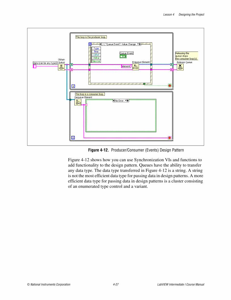
Lesson 4 Designing the Project
© National Instruments Corporation 4-27 LabVIEW Intermediate I Course Manual
Figure 4-12. Producer/Consumer (Events) Design Pattern
Figure 4-12 shows how you can use Synchronization VIs and functions to add functionality to the design pattern. Queues have the ability to transfer any data type. The data type transferred in Figure 4-12 is a string. A string is not the most efficient data type for passing data in design patterns. A more efficient data type for passing data in design patterns is a cluster consisting of an enumerated type control and a variant.
Lesson 4 Designing the Project
LabVIEW Intermediate I Course Manual 4-28 ni.com
Exercise 4-3 Concept: Experiment with Event-Based Design Patterns
GoalObserve the functionality and design of event-based LabVIEW design patterns.
DescriptionExplore the event-based design pattern VI templates that ship with LabVIEW and observe how they operate. Use the event-based design pattern VI templates in LabVIEW as the basis for the underlying architecture of VIs you create.
1. Select File»New to open the New dialog box.
2. In the Create New section, expand the VI»from Template»Frameworks»Design Patterns tree.
3. Select the User Interface Event Handler design pattern from the tree and click the OK button to open the template.
4. Open the block diagram, turn execution highlighting on, and run the VI.
Notice how the design pattern handles the following items:
❑ State transitions
❑ Data flow
❑ VIs used to create design patterns
5. Close the design pattern. Do not save changes.
6. Repeat steps 1 through 5 to observe the operation of the Producer/Consumer Design Pattern (Events) design pattern
End of Exercise 4-3
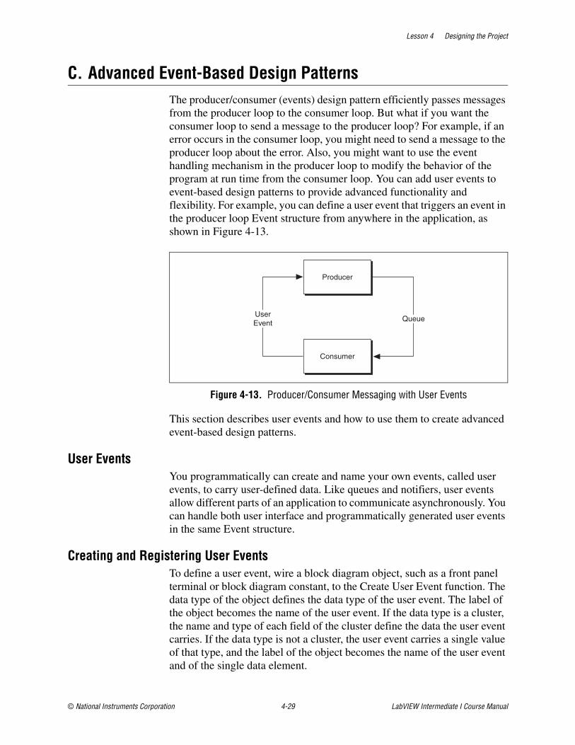
Lesson 4 Designing the Project
© National Instruments Corporation 4-29 LabVIEW Intermediate I Course Manual
C. Advanced Event-Based Design PatternsThe producer/consumer (events) design pattern efficiently passes messages from the producer loop to the consumer loop. But what if you want the consumer loop to send a message to the producer loop? For example, if an error occurs in the consumer loop, you might need to send a message to the producer loop about the error. Also, you might want to use the event handling mechanism in the producer loop to modify the behavior of the program at run time from the consumer loop. You can add user events to event-based design patterns to provide advanced functionality and flexibility. For example, you can define a user event that triggers an event in the producer loop Event structure from anywhere in the application, as shown in Figure 4-13.
Figure 4-13. Producer/Consumer Messaging with User Events
This section describes user events and how to use them to create advanced event-based design patterns.
User EventsYou programmatically can create and name your own events, called user events, to carry user-defined data. Like queues and notifiers, user events allow different parts of an application to communicate asynchronously. You can handle both user interface and programmatically generated user events in the same Event structure.
Creating and Registering User EventsTo define a user event, wire a block diagram object, such as a front panel terminal or block diagram constant, to the Create User Event function. The data type of the object defines the data type of the user event. The label of the object becomes the name of the user event. If the data type is a cluster, the name and type of each field of the cluster define the data the user event carries. If the data type is not a cluster, the user event carries a single value of that type, and the label of the object becomes the name of the user event and of the single data element.
Producer
Consumer
UserEvent
Queue
Lesson 4 Designing the Project
LabVIEW Intermediate I Course Manual 4-30 ni.com
The user event out output of the Create User Event function is a strictly typed refnum that carries the name and data type of the user event. Wire the user event out output of the Create User Event function to an event source input of the Register For Events function.
You cannot register for a user event statically. Handle a user event the same way you handle a dynamically registered user interface event. Wire the event registration refnum output of the Register For Events function to the dynamic event terminal on the left side of the Event structure. Use the Edit Events dialog box to configure a case in the Event structure to handle the event. The name of the user event appears under the Dynamic subheading in the Event Sources section of the dialog box.
The user event data items appear in the Event Data Node on the left border of the Event structure. User events are notify events and can share the same event case of an Event structure as user interface events or other user events.
You can wire a combination of user events and user interface events to the Register For Events function.
Generating User EventsUse the Generate User Event function to deliver the user event and associated data to other parts of an application through an Event structure configured to handle the event. The Generate User Event function accepts a user event refnum and a value for the event data. The data value must match the data type of the user event.
If the user event is not registered, the Generate User Event function has no effect. If the user event is registered but no Event structure is waiting on it, LabVIEW queues the user event and data until an Event structure executes to handle the event. You can register for the same user event multiple times by using separate Register For Event functions, in which case each queue associated with an event registration refnum receives its own copy of the user event and associated event data each time the Generate User Event function executes.
Note To simulate user interaction with a front panel, you can create a user event that has event data items with the same names and data types as an existing user interface event. For example, you can create a user event called MyValChg by using a cluster of two Boolean fields named OldVal and NewVal, which are the same event data items the Value Change user interface event associates with a Boolean control. You can share the same Event structure case for the simulated MyValChg user event and a real Boolean Value Change event. The Event structure executes the event case if a Generate User Event function generates the user event or if a user changes the value of the control.
Lesson 4 Designing the Project
© National Instruments Corporation 4-31 LabVIEW Intermediate I Course Manual
Unregistering User EventsUnregister user events when you no longer need them. In addition, destroy the user event by wiring the user event refnum to the user event input of the Destroy User Event function. Wire the error out output of the Unregister For Events function to the error in input of the Destroy User Event function to ensure that the functions execute in the correct order.
LabVIEW unregisters all events and destroys existing user events automatically when the top-level VI finishes running. However, National Instruments recommends that you unregister and destroy user events explicitly, especially in a long-running application, to conserve memory resources.
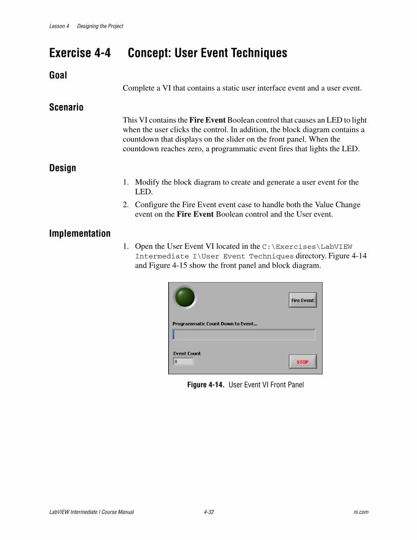
Lesson 4 Designing the Project
LabVIEW Intermediate I Course Manual 4-32 ni.com
Exercise 4-4 Concept: User Event Techniques
GoalComplete a VI that contains a static user interface event and a user event.
ScenarioThis VI contains the Fire Event Boolean control that causes an LED to light when the user clicks the control. In addition, the block diagram contains a countdown that displays on the slider on the front panel. When the countdown reaches zero, a programmatic event fires that lights the LED.
Design1. Modify the block diagram to create and generate a user event for the
LED.
2. Configure the Fire Event event case to handle both the Value Change event on the Fire Event Boolean control and the User event.
Implementation1. Open the User Event VI located in the C:\Exercises\LabVIEW
Intermediate I\User Event Techniques directory. Figure 4-14 and Figure 4-15 show the front panel and block diagram.
Figure 4-14. User Event VI Front Panel

Lesson 4 Designing the Project
© National Instruments Corporation 4-33 LabVIEW Intermediate I Course Manual
Figure 4-15. User Event VI Block Diagram
Create and Generate User Event2. Modify the block diagram to create and generate a user event for the
LED as shown in Figure 4-16.
Figure 4-16. Create and Generate a User Event for LED
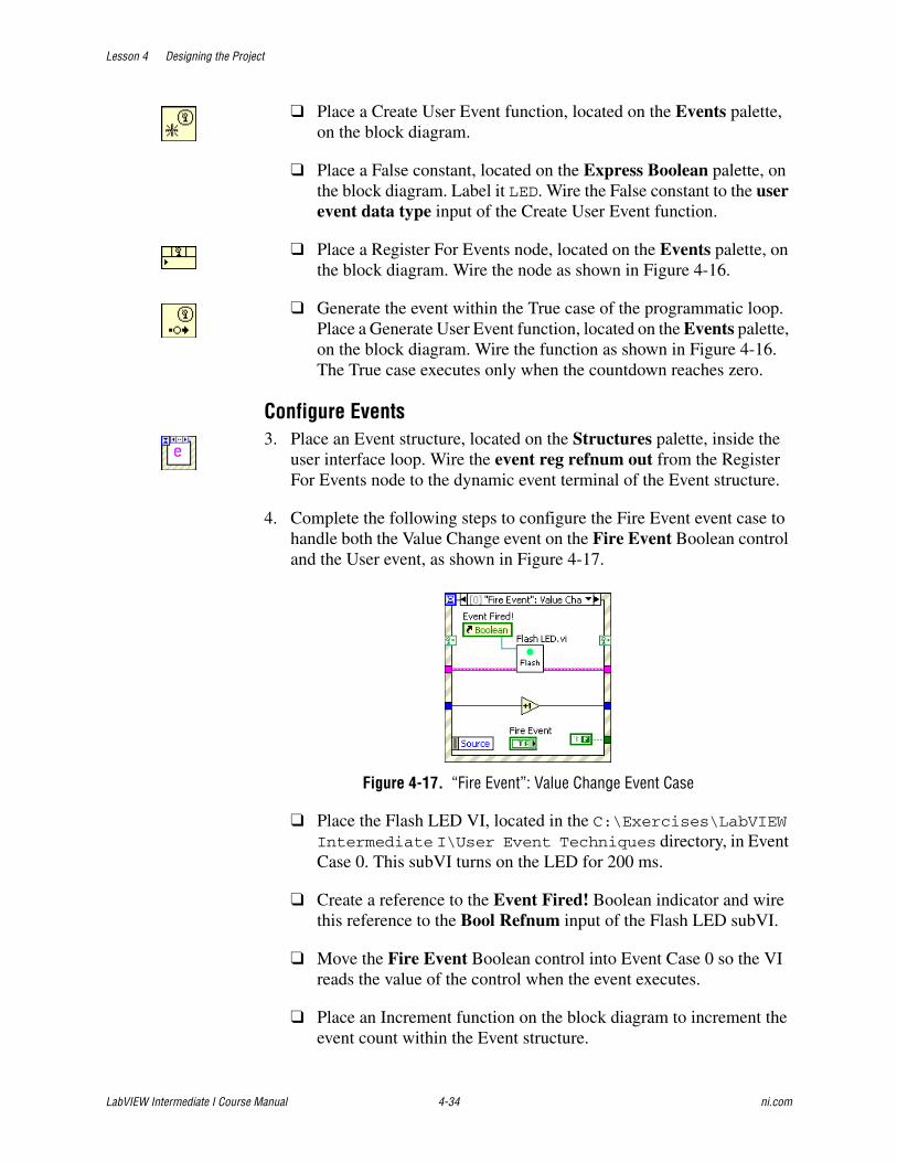
Lesson 4 Designing the Project
LabVIEW Intermediate I Course Manual 4-34 ni.com
❑ Place a Create User Event function, located on the Events palette, on the block diagram.
❑ Place a False constant, located on the Express Boolean palette, on the block diagram. Label it LED. Wire the False constant to the user event data type input of the Create User Event function.
❑ Place a Register For Events node, located on the Events palette, on the block diagram. Wire the node as shown in Figure 4-16.
❑ Generate the event within the True case of the programmatic loop. Place a Generate User Event function, located on the Events palette, on the block diagram. Wire the function as shown in Figure 4-16. The True case executes only when the countdown reaches zero.
Configure Events3. Place an Event structure, located on the Structures palette, inside the
user interface loop. Wire the event reg refnum out from the Register For Events node to the dynamic event terminal of the Event structure.
4. Complete the following steps to configure the Fire Event event case to handle both the Value Change event on the Fire Event Boolean control and the User event, as shown in Figure 4-17.
Figure 4-17. “Fire Event”: Value Change Event Case
❑ Place the Flash LED VI, located in the C:\Exercises\LabVIEW Intermediate I\User Event Techniques directory, in Event Case 0. This subVI turns on the LED for 200 ms.
❑ Create a reference to the Event Fired! Boolean indicator and wire this reference to the Bool Refnum input of the Flash LED subVI.
❑ Move the Fire Event Boolean control into Event Case 0 so the VI reads the value of the control when the event executes.
❑ Place an Increment function on the block diagram to increment the event count within the Event structure.
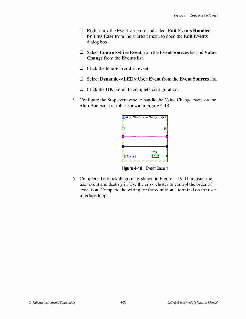
Lesson 4 Designing the Project
© National Instruments Corporation 4-35 LabVIEW Intermediate I Course Manual
❑ Right-click the Event structure and select Edit Events Handled by This Case from the shortcut menu to open the Edit Events dialog box.
❑ Select Controls»Fire Event from the Event Sources list and Value Change from the Events list.
❑ Click the blue + to add an event.
❑ Select Dynamic»<LED>:User Event from the Event Sources list.
❑ Click the OK button to complete configuration.
5. Configure the Stop event case to handle the Value Change event on the Stop Boolean control as shown in Figure 4-18.
Figure 4-18. Event Case 1
6. Complete the block diagram as shown in Figure 4-19. Unregister the user event and destroy it. Use the error cluster to control the order of execution. Complete the wiring for the conditional terminal on the user interface loop.
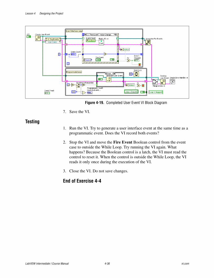
Lesson 4 Designing the Project
LabVIEW Intermediate I Course Manual 4-36 ni.com
Figure 4-19. Completed User Event VI Block Diagram
7. Save the VI.
Testing1. Run the VI. Try to generate a user interface event at the same time as a
programmatic event. Does the VI record both events?
2. Stop the VI and move the Fire Event Boolean control from the event case to outside the While Loop. Try running the VI again. What happens? Because the Boolean control is a latch, the VI must read the control to reset it. When the control is outside the While Loop, the VI reads it only once during the execution of the VI.
3. Close the VI. Do not save changes.
End of Exercise 4-4
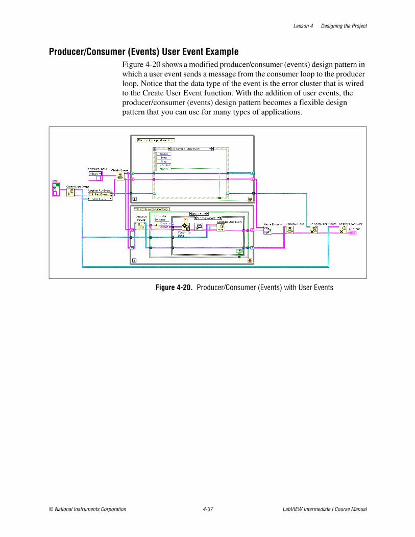
Lesson 4 Designing the Project
© National Instruments Corporation 4-37 LabVIEW Intermediate I Course Manual
Producer/Consumer (Events) User Event ExampleFigure 4-20 shows a modified producer/consumer (events) design pattern in which a user event sends a message from the consumer loop to the producer loop. Notice that the data type of the event is the error cluster that is wired to the Create User Event function. With the addition of user events, the producer/consumer (events) design pattern becomes a flexible design pattern that you can use for many types of applications.
Figure 4-20. Producer/Consumer (Events) with User Events
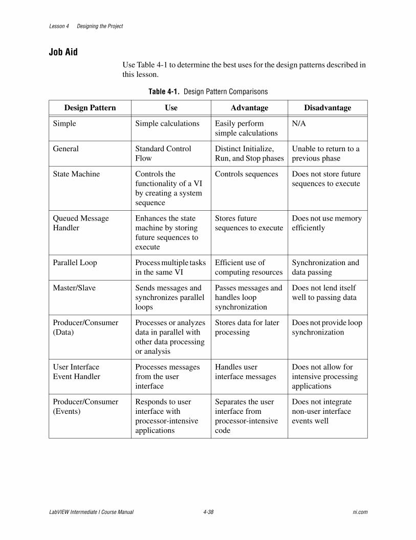
Lesson 4 Designing the Project
LabVIEW Intermediate I Course Manual 4-38 ni.com
Job AidUse Table 4-1 to determine the best uses for the design patterns described in this lesson.
Table 4-1. Design Pattern Comparisons
Design Pattern Use Advantage Disadvantage
Simple Simple calculations Easily perform simple calculations
N/A
General Standard Control Flow
Distinct Initialize, Run, and Stop phases
Unable to return to a previous phase
State Machine Controls the functionality of a VI by creating a system sequence
Controls sequences Does not store future sequences to execute
Queued Message Handler
Enhances the state machine by storing future sequences to execute
Stores future sequences to execute
Does not use memory efficiently
Parallel Loop Process multiple tasks in the same VI
Efficient use of computing resources
Synchronization and data passing
Master/Slave Sends messages and synchronizes parallel loops
Passes messages and handles loop synchronization
Does not lend itself well to passing data
Producer/Consumer (Data)
Processes or analyzes data in parallel with other data processing or analysis
Stores data for later processing
Does not provide loop synchronization
User Interface Event Handler
Processes messages from the user interface
Handles user interface messages
Does not allow for intensive processing applications
Producer/Consumer (Events)
Responds to user interface with processor-intensive applications
Separates the user interface from processor-intensive code
Does not integrate non-user interface events well
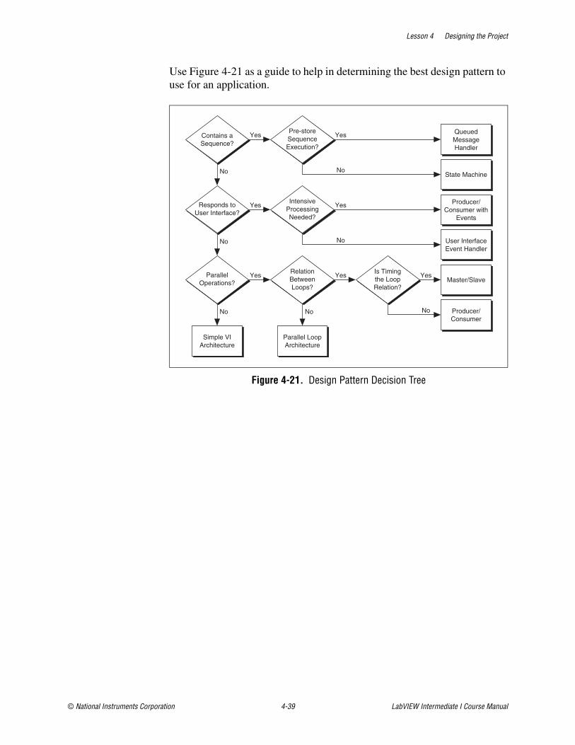
Lesson 4 Designing the Project
© National Instruments Corporation 4-39 LabVIEW Intermediate I Course Manual
Use Figure 4-21 as a guide to help in determining the best design pattern to use for an application.
Figure 4-21. Design Pattern Decision Tree
User InterfaceEvent Handler
Producer/Consumer with
Events
QueuedMessageHandler
State Machine
Master/Slave
Producer/Consumer
YesYesYesParallelOperations?
RelationBetweenLoops?
Is Timingthe LoopRelation?
Responds toUser Interface?
IntensiveProcessingNeeded?
Yes
Contains aSequence?
Pre-storeSequenceExecution?
Yes Yes
Yes
No
No
No
No
No
No No
Simple VIArchitecture
Parallel LoopArchitecture
Lesson 4 Designing the Project
LabVIEW Intermediate I Course Manual 4-40 ni.com
Exercise 4-5 Choose a Scalable Architecture
GoalDetermine the appropriate design pattern to use for a scalable architecture for the application.
ScenarioEvaluate each of the design patterns and pick the best pattern to implement the Theatre Light Control Software application.
Implementation1. Run Design Pattern.exe in the C:\Exercises\LabVIEW
Intermediate I\Choose a Scalable Architecture directory.
End of Exercise 4-5
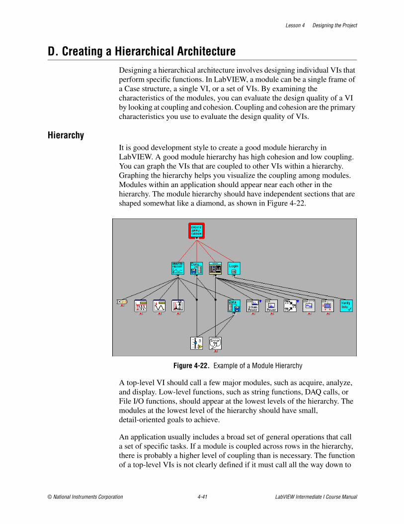
Lesson 4 Designing the Project
© National Instruments Corporation 4-41 LabVIEW Intermediate I Course Manual
D. Creating a Hierarchical ArchitectureDesigning a hierarchical architecture involves designing individual VIs that perform specific functions. In LabVIEW, a module can be a single frame of a Case structure, a single VI, or a set of VIs. By examining the characteristics of the modules, you can evaluate the design quality of a VI by looking at coupling and cohesion. Coupling and cohesion are the primary characteristics you use to evaluate the design quality of VIs.
HierarchyIt is good development style to create a good module hierarchy in LabVIEW. A good module hierarchy has high cohesion and low coupling. You can graph the VIs that are coupled to other VIs within a hierarchy. Graphing the hierarchy helps you visualize the coupling among modules. Modules within an application should appear near each other in the hierarchy. The module hierarchy should have independent sections that are shaped somewhat like a diamond, as shown in Figure 4-22.
Figure 4-22. Example of a Module Hierarchy
A top-level VI should call a few major modules, such as acquire, analyze, and display. Low-level functions, such as string functions, DAQ calls, or File I/O functions, should appear at the lowest levels of the hierarchy. The modules at the lowest level of the hierarchy should have small, detail-oriented goals to achieve.
An application usually includes a broad set of general operations that call a set of specific tasks. If a module is coupled across rows in the hierarchy, there is probably a higher level of coupling than is necessary. The function of a top-level VIs is not clearly defined if it must call all the way down to
Lesson 4 Designing the Project
LabVIEW Intermediate I Course Manual 4-42 ni.com
the lowest level of the hierarchy. Every software design needs to strike a balance on the acceptable level of coupling.
Plan your application before you build it. Think about what operations are necessary. A complex application includes major tasks, such as network communication or data acquisition, and minor tasks, such as user login or dialog box display. Most of the smallest tasks, such as string concatenation and basic mathematics, have existing VIs or functions in LabVIEW. Try to build modules that have only one goal and accomplish that goal well.
If you are editing an existing VI, understand what function each part of the block diagram performs before you insert new functionality. Strive to achieve strong cohesion. Mimic existing organization patterns. If all existing waveform calculations occur in one module, make sure that you add any new waveform calculations to the same module.
Job AidUse the following checklist to create a hierarchical architecture and determine if each VI uses the correct level of detail.
❑ Each individual VI performs a single goal
❑ Each VI is loosely coupled
❑ Implementation details of the VI are hidden
❑ You can reuse each VI in other VIs
❑ Each VI has clearly defined inputs and outputs
E. Using the LabVIEW Project and Project LibrariesUse projects and project libraries to manage the files in complex applications.
Using the LabVIEW Project
Use projects to group together LabVIEW files and non-LabVIEW files, create build specifications, and deploy or download files to targets. When you save a project, LabVIEW creates a project file (.lvproj), which includes references to files in the project, configuration information, build information, deployment information, and so on.
You must use a project to build applications and shared libraries. You also must use a project to work with an RT, FPGA, or PDA target. Refer to the specific module documentation for more information about using projects with the LabVIEW Real-Time, FPGA, and PDA Modules.
Lesson 4 Designing the Project
© National Instruments Corporation 4-43 LabVIEW Intermediate I Course Manual
If you are using a project with an NI device driver, refer to the specific driver documentation for more information about using projects with drivers.
Project Explorer WindowUse the Project Explorer window to create and edit LabVIEW projects. Select File»New Project to display the Project Explorer window. You also can select Project»New Project or select Empty Project in the New dialog box to display the Project Explorer window.
The Project Explorer window includes the following items by default:
• Project root—Contains all other items in the Project Explorer window. This label on the project root includes the filename for the project.
– My Computer—Represents the local computer as a target in the project.
– Dependencies—Includes items that VIs under a target require.
– Build Specifications—Includes build configurations for source distributions and other types of builds available in LabVIEW toolkits and modules. If you have the LabVIEW Professional Development System or Application Builder installed, you can use Build Specifications to configure stand-alone applications (EXEs), shared libraries (DLLs), installers, and zip files.
Creating a LabVIEW ProjectYou must use a project to build applications and shared libraries. You also must use a project to work with an RT, FPGA, or PDA target. Refer to the specific module documentation for more information about using projects with the LabVIEW Real-Time, FPGA, and PDA Modules.
Complete the following steps to create a project.
1. Select File»New Project to display the Project Explorer window. You also can select Project»New Project or select Empty Project in the New dialog box to display the Project Explorer window.
2. Add items you want to include in the project under a target, such as My Computer.
3. Select File»Save Project to save the project.
Saving a ProjectYou can save a LabVIEW project in the following ways:
• Select File»Save Project.
• Select Project»Save Project.
• Right-click the project root and select Save from the shortcut menu.

Lesson 4 Designing the Project
LabVIEW Intermediate I Course Manual 4-44 ni.com
• Click the Save Project button on the Project toolbar.
You must save new, unsaved files in a project before you can save the project. When you save a project, LabVIEW does not save items under Dependencies as part of the project file.
Note Make a backup copy of a project when you prepare to make major revisions to the project.
Note When you save dependencies, LabVIEW does not save the project file. Select File»Save All to save the project file and all dependencies.
Adding Items to a ProjectUse the Project Explorer window to add LabVIEW files, such as VIs and LLBs, as well as non-LabVIEW files, such as text files and spreadsheets, to a target in a LabVIEW project. An item can only appear once under a target. For example, if you add a file from a folder on disk to the My Computer target and then add the entire folder on disk to the My Computer target, LabVIEW does not include the file again.
You can add items under a target in a project in the following ways:
• Right-click a target or a folder under the target, select Add»File from the shortcut menu, and select the file(s) you want to add from the file dialog box. You also can select the target, select Project»Add To Project»Add File, and select the file(s) you want to add from the dialog box.
• Right-click a target or a folder under the target and select Add»Folder from the shortcut menu to add a folder. You also can select the target and then select Project»Add To Project»Add Folder to add a folder. Selecting a folder on disk adds contents of the entire folder, including files and contents of subfolders.
Note After you add a folder on disk to a project, LabVIEW does not automatically update the folder in the project if you make changes to the folder on disk.
• Right-click a target and select New»VI from the shortcut menu to add a new, blank VI. You also can select File»New VI or Project»Add To Project»New VI to add a new, blank VI.
• Select the VI icon in the upper right corner of a front panel or block diagram window and drag the icon to the target.
• (Windows and Mac) Select an item or folder from the file system on your computer and drag it to the target.
Note You cannot drag and drop items in the Project Explorer window to the file system.
Lesson 4 Designing the Project
© National Instruments Corporation 4-45 LabVIEW Intermediate I Course Manual
You also can add new LabVIEW files to a project from the New dialog box. Select File»New or Project»Add To Project»New to display the New dialog box. In the New dialog box, select the item you want to add and place a checkmark in the Add to project checkbox. If you have multiple projects open, select the project to which you want to add the item from the Projects list.
Items you add to the Project Explorer window can include icons.
Project DependenciesUse Dependencies to view items that VIs under a target require. Each target in a LabVIEW project includes Dependencies.
You cannot add items directly to Dependencies. LabVIEW adds dependencies for VIs under a target when you right-click Dependencies and select Refresh from the shortcut menu. For example, if you add a VI that includes a subVI to a target, LabVIEW adds the subVI to Dependencies when you select Refresh. However, if you add a dependent item under a target, the item does not appear under Dependencies. For example, if you add the VI and the subVI under the target, LabVIEW does not add the subVI under Dependencies when you select Refresh.
Dependencies include VIs, DLLs, and LabVIEW project libraries that a VI calls statically.
Note Items that a VI calls dynamically do not appear under Dependencies. You must add these items under a target to manage them in a project.
LabVIEW tracks subVIs recursively. LabVIEW does not track DLLs recursively. For example, if a.vi calls b.dll statically and b.dll calls c.dll statically, LabVIEW only considers b.dll as a dependent item. To manage c.dll in the project, you must explicitly add c.dll under the target.
If a dependent item is part of a project library, LabVIEW includes the entire project library under Dependencies.
You cannot create new items under Dependencies. You cannot drag items from other places in the Project Explorer window to Dependencies.
You can remove items under Dependencies.
When you save a project, LabVIEW does not save the dependencies as part of the project file. When you open a project file, you must right-click Dependencies and select Refresh from the shortcut menu to view the dependencies.
Lesson 4 Designing the Project
LabVIEW Intermediate I Course Manual 4-46 ni.com
Removing Items from ProjectsUse the Project Explorer window to remove items from a LabVIEW project. You can remove items in the following ways:
• Right-click the item you want to remove and select Remove from the shortcut menu.
• Select the item you want to remove and press the <Delete> key.
• Select the item you want to remove and press the Delete button on the Standard toolbar.
Note Removing an item from a project does not delete the corresponding item on disk.
Using Project LibrariesLabVIEW project libraries are collections of VIs, type definitions, shared variables, palette menu files, and other files, including other project libraries. When you create and save a new project library, LabVIEW creates a project library file (.lvlib), which includes the properties of the project library and the references to files that the project library owns.
Project libraries are useful if you want to organize files into a single hierarchy of items, avoid potential VI name duplication, limit public access to certain files, limit editing permission for a collection of files, and set a default palette menu for a group of VIs. You can drag items that a project library owns from the Project Explorer window to the block diagram or front panel.
You can view the structure of a project library from the Project Explorer window or in a stand-alone project library window. If you are not in the Project Explorer window, double-click a project library file to open it in the project library window.
Use project libraries to organize a virtual, logical hierarchy of items. A project library file does not contain the actual files it owns, unlike an LLB, which is a physical directory that contains VIs. Files that a project library owns still appear individually on disk in the directories where you saved them. A project library might have a different organizational structure than its files on disk.
Use project libraries to qualify the names of VIs and other LabVIEW files. LabVIEW identifies VIs by filename, so LabVIEW unintentionally might load and reference a VI because the VI has the same filename as another VI, a problem known as cross-linking. When a VI is part of a project library, LabVIEW qualifies the VI name with the project library name to avoid cross-linking. A qualified filename includes the filename and the owning project library filename.
Lesson 4 Designing the Project
© National Instruments Corporation 4-47 LabVIEW Intermediate I Course Manual
For example, if you build a VI named caller.vi that includes a subVI named init.vi that library1.lvlib owns, you also can include a different subVI named init.vi that library2.lvlib owns and avoid cross-linking problems. The qualified filenames that LabVIEW records when you save caller.vi are library1.lvlib:init.vi and library2.lvlib:init.vi respectively.
Note Only one project library can own a specific VI. However, you can associate a non-LabVIEW file with multiple project libraries.
You can specify version numbers in a project library to distinguish changes to the collection of files over time. Set version numbers from the General Settings page of the Project Library Properties dialog box and update the numbers periodically. The version number does not affect the project library name.
Caution You must right-click the project library and select Save As or Rename from the shortcut menu to rename project libraries. If you rename a project library outside LabVIEW, you might break the project library.
Use project libraries to limit access to certain types of files. You can configure access to items and folders in a project library as public or private to prevent users from accessing certain items. When you set access for a folder as private, all VIs in that folder also have private access.
You can limit editing permission by locking or password-protecting project libraries. When you lock a project library, users cannot add or remove items and cannot view items that you set as private. When you assign a password to a project library, users cannot add or remove items or edit project library properties without a password. Users can open the Project Library Properties dialog box, but all dialog box components except protection options are disabled. Users must unlock the project library or enter a password to enable the dialog box components.
Note Adding password protection to a project library does not add password protection to the VIs it owns. You must assign password protection to individual VIs.
You can create project libraries from project folders. You also can convert LLBs to project libraries. LLBs have different features and advantages than project libraries, so consider the ways in which you might use an LLB before you decide whether to convert it to a project library. You can include project library files in an LLB.
If you include a palette menu file (.mnu) in a project library, you can set it as the default palette menu for all VIs that the project library owns. After
Lesson 4 Designing the Project
LabVIEW Intermediate I Course Manual 4-48 ni.com
you select a default palette menu, you can right-click a subVI call to any VI that the project library owns and view the default palette for that subVI from the shortcut menu. From the General Settings page of the Project Library Properties dialog box, select the menu file in the Default Palette ring control. You also can set the default palette menu from the Item Settings page. Select the .mnu file in the Contents tree and place a checkmark in the Default Palette checkbox.
Project SublibrariesProject sublibraries are project libraries that another project library owns. The settings in the owning project library do not affect access settings and editing permission for items within the project sublibrary. You can set the access of a project sublibrary file (.lvlib) as private within the owning project library, but when you edit the project sublibrary itself, items the sublibrary owns retain public or private access settings.
Project sublibraries are useful if you want to create a project library that includes separate areas of functionality. For example, if you are creating a project library of graphics tools, you might divide the two-dimensional and three-dimensional drawing tools into separate sublibraries. Each project sublibrary can include private and public access items and folders.
Creating a Project LibraryComplete the following steps to create a project library.
1. From the Project Explorer window, right-click My Computer and select New»Library from the shortcut menu. LabVIEW creates a project library file that appears in the Project Explorer window as part of the LabVIEW project.
You also can select File»New to display the New dialog box. In the Other Files folder of the Create New tree, double-click the Library option. A stand-alone project library window for the new project library file appears.
2. To add files to a project library, right-click the project library icon and select Add File or Add Folder from the shortcut menu. You can add the same types of files that you can add to projects. You also can drag an item in the project so it appears under the project library.
Note Only one project library can own a specific VI. However, you can associate a non-LabVIEW file with multiple project libraries.
Note If you add a VI that is not in memory to a project library, a dialog box appears that prompts you to save changes to the VI. Save changes to the VI so it will link correctly to the owning project library.
Lesson 4 Designing the Project
© National Instruments Corporation 4-49 LabVIEW Intermediate I Course Manual
3. Select File»Save All or right-click the project library icon and select Save As from the shortcut menu to name and save the project library file.
4. Right-click the project library icon and select Properties from the shortcut menu to display the Project Library Properties dialog box.
5. From the General Settings page, set the version number, create or select an icon, and assign security settings to the project library.
Note The icon you select becomes the default icon for any VIs you create from within the project library. You can create a template icon to edit and use in all VIs that a project library owns.
6. From the Documentation page, enter information for context help for the project library.
7. From the Item Settings page, set access options for files in the project library.
8. Click the OK button to update the project library with the edited settings and close the dialog box.
You also can create a project library from a project folder.
Creating a Project Library from a Project Folder You can create LabVIEW project libraries from folders in a LabVIEW project. The new project library owns the items that the folder contained.
From the Project Explorer window, right-click the folder to convert and select Convert To Library from the shortcut menu. LabVIEW converts the folder to a project library, which appears in the Project Explorer window with the items it owns listed under it.
You can name the new project library file when you save it. Right-click the project library and select Save As from the shortcut menu.
Configuring Access Options in Project LibrariesYou can configure access settings for items and folders that a LabVIEW project library owns as public or private. If you set an item as private and lock the project library, the item is not visible in the project library or in palettes. You cannot use a private VI as a subVI in other VIs or applications that the project library does not own, even if the project library is unlocked.
Determine which items in the project library you want to set as public and which as private. Public items might include palette VIs, XControls, instrument drivers, and other tools you want users to find and use. Private
Lesson 4 Designing the Project
LabVIEW Intermediate I Course Manual 4-50 ni.com
items might include support VIs, copyrighted files, or items you might want to edit later without taking the risk of breaking users' code.
You can set the access of a project sublibrary file (.lvlib) as private within the owning project library, but when you edit the project sublibrary itself, items the sublibrary owns retain public or private access settings.
Complete the following steps to configure access options in a project library.
1. Right-click the project library icon in the Project Explorer or stand-alone project library window and select Properties from the shortcut menu to display the Project Library Properties dialog box.
2. From the Item Settings page, click an item in the Contents tree to select it. The current access settings for the item appear in the Access Scope box. Click one of the following radio buttons in the Access Scope box to apply to the item.
– Public—The item is visible when users view the project library. Other VIs and applications can call public VIs.
– Private—The item does not appear visible when users view the project library or palettes if you lock the project library. Other VIs and applications that the project library does not own cannot call a private VI.
– Not specified—This option appears only when you select a folder. The folder does not have access items specified. Access is public. By default, folders in a project library do not have access specified, which means the folders are publicly accessible.
Note If you specify access options for a folder, the access setting applies to all items in the folder and overrides access options for individual items in the folder.
Note You can set individual instances of a polymorphic VI as private and set the primary polymorphic VI as public. The polymorphic VI does not break even though instance VIs are private. Setting instance VIs as private is useful if you want users to access instances only through the polymorphic VI selector, so you can edit instance order without causing user problems.
3. Click the OK button to incorporate the changes into the project library and close the dialog box.
Items set as private appear in the Project Explorer window with a private icon. If you lock the project library, private items do not appear in the Project Explorer window.
Lesson 4 Designing the Project
© National Instruments Corporation 4-51 LabVIEW Intermediate I Course Manual
Protecting Project LibrariesYou can limit editing permission by locking or password-protecting LabVIEW project libraries. When you lock a project library, users cannot add or remove items and cannot view items that you set as private. When you assign a password to a project library, users cannot add or remove items or edit project library properties without a password. Users can open the Project Library Properties dialog box, but all dialog box components except protection options are disabled. Users must unlock the project library or enter a password to enable the dialog box components.
Note Adding password protection to a project library does not add password protection to the VIs it owns. You must assign password protection to individual VIs.
Complete the following steps to set levels of protection for a project library.
1. Right-click the project library icon in the Project Explorer or stand-alone project library window and select Properties from the shortcut menu to display the Project Library Properties dialog box.
2. From the General Settings page, select one of the following options to apply to the project library.
– Unlocked (no password)—Users can view public and private items that the project library owns and can edit the project library and its properties.
– Locked (no password)—Users cannot add or remove items from the project library, edit project library properties, or view private items that the project library owns. For example, if you are developing a project library and do not want anyone to view private files, you should lock the project library.
– Password-protected—Users cannot add or remove items from the project library, edit project library properties, or view private items that the project library owns. Users must enter a password to edit the project library. For example, if you are developing a project library and want only a few people on the development team to have editing permission, set a password for the project library and give the password to those people.
3. If you select Password-protected, a dialog box displays in which you set and confirm the password.
4. Click the OK button to incorporate the changes into the project library and close the dialog box.
Note If you set a password for the project library, the password does not take effect until you clear the password cache or restart LabVIEW. You can clear the password cache from the Environment page of the Options dialog box.

Lesson 4 Designing the Project
LabVIEW Intermediate I Course Manual 4-52 ni.com
Organizing Project LibrariesYou can create an organizational structure for files that a LabVIEW project library owns. A well-organized structure for project library items can make it easier for you to use source control, avoid filename conflicts, and divide the project library into public and private access areas.
The following list describes some of the caveats and recommendations to consider when you organize project libraries and the files that the project libraries own:
• Create each project library within a separate LabVIEW project that contains only files related to that project library, including example files and the files you use to create and test the project library. Give the project and project library similar filenames. If a project library includes several separate areas of functionality, consider using project sublibraries for each area.
• Create a separate directory of files for each project library you create. You can include the files that the project library owns in the directory. If you include files for more than one project library in the same directory, conflicts might occur if you try to include VIs of the same name in different libraries. Organizing project library files into separate directories makes it easier to identify files related to specific project libraries on disk.
• If you move files on disk that a project library owns, reopen and resave the project library to ensure that the project library links correctly to the moved items.
• (Windows) If you are building an installer that includes a project library, make sure you save the files that the project library owns on the same drive as the project library. If some files are on a different drive, such as a network drive, project library links will break if you include the project library in an installer.
• Determine which items in a project library you want to set as private and which as public. Users cannot use private VIs as subVIs in other VIs or applications. Public items provide the interface to the project library functionality and might include palette VIs, XControls, instrument drivers, and tools you want users to find and use. Private items might include support VIs, copyrighted files, or items you might want to edit later without taking the risk of breaking users' code. Consider the following recommendations:
– Create a folder in the project library named private. From the Item Settings page of the Project Library Properties dialog box, configure the access settings as private for the folder. LabVIEW automatically sets as private any project library files you add to the private folder, so you do not have to configure access settings for individual VIs.
Lesson 4 Designing the Project
© National Instruments Corporation 4-53 LabVIEW Intermediate I Course Manual
– Assume that all project library files that are not in the private folder are public. You do not need to create a folder for public files.
– You also can organize public and private items in a project library by creating folders for each functionality group within a project library and adding a private subfolder within each functionality group folder.
• Adding password protection to a project library does not add password protection to the VIs it owns. You must assign password protection to individual VIs if you want to limit edits to the block diagrams and front panels. Consider using the same password for the project library and for the VIs the project library owns to avoid confusion.
Lesson 4 Designing the Project
LabVIEW Intermediate I Course Manual 4-54 ni.com
Exercise 4-6 Using the LabVIEW Project
GoalCreate a LabVIEW project for the application.
ScenarioEvery large LabVIEW development needs to use a project to control naming and project hierarchy. Using the LabVIEW Project simplifies the development of larger applications.
DesignCreate a LabVIEW project that includes folders for modules and controls. Save the project as TLC.lvproj in the C:\Exercises\LabVIEW Intermediate I directory.
Implementation
1. Launch LabVIEW.
2. Create a new project.
❑ Select File»New Project to open the Project Explorer window.
3. Create a folder for modules and a folder for controls in the My Computer hierarchy. You use these folders later in the course.
❑ Right-click My Computer in the Project Explorer window and select New»Folder from the shortcut menu to create a new folder.
❑ Name the folder Modules.
❑ Repeat the previous steps to create the Controls folder.
4. Save the project as TLC.lvproj.
❑ Select File»Save Project.
❑ Save the project as TLC.lvproj in the C:\Exercises\LabVIEW Intermediate I\Course Project directory.
End of Exercise 4-6
Lesson 4 Designing the Project
© National Instruments Corporation 4-55 LabVIEW Intermediate I Course Manual
F. Choosing Data TypesWhen you develop a software design, it is important to analyze the data that the application uses and determine how you want to represent the data. LabVIEW gives you three choices for data representation. You can represent the data as a scalar, an array, or a cluster. Each of these representations provides a level of functionality that improves the design of the software. The appropriate time to determine what data structures you want to use to represent the data is during the design phase.
ScalarsScalar data is the most basic data structure in LabVIEW. Scalar data can be a number or a Boolean value. Use scalar data in your VIs for items that contain only a single value. For example, if your software requirements specify the use of a stop button in a VI, design a data structure that uses a single Boolean stop button. If the VI requires that you use a device number to specify the hardware to access, design a data structure that contains an integer numeric to contain the device number. Examine all aspects of a software requirements document and identify all data elements that are appropriately represented as scalar data.
Because the dataflow programming model of LabVIEW is tightly integrated with the data that a VI uses, you must evaluate each data element. If you know that scalar data will always remain scalar, even as the program evolves, you can use scalar data structures in the design of the software. Because scalars are the most basic data structure in LabVIEW, VIs that use primarily scalar data have the highest levels of efficiency and performance. However, if you know that an application will evolve over time and require more advanced data structures to replace the scalars, it may be difficult to modify the application if you initially build it using scalar data structures.
ArraysArrays group data elements of the same type. Arrays are powerful data structures for storing sets of the same data type where each data element is associated with the others. Use arrays to contain data that includes more than one element of the same data type and each element is associated with one another. For example, if you need to contain data that streams from a hardware device, such as a DAQ device, design a data structure that includes an array to handle that data. Storing the streaming data into individual scalar elements is impractical and results in a VI that is difficult to debug and use.
ClustersClusters enable you to create data structures that contain any type of data. A cluster is useful for storing data about objects. When you create software, you might need to model real-world items. For example, you might need to
Lesson 4 Designing the Project
LabVIEW Intermediate I Course Manual 4-56 ni.com
create a model of an employee for a company. In this case, the VI should be able to store data about the employee, such as their name, social security number, date of birth, and home address. You can place all the individual data elements into a single cluster labeled employee. Use clusters to group data into an individual data type. If you store the data as scalar data and do not group the data, it is difficult to process the data.
Job AidUse the following checklist to help identify appropriate data structures.
❑ Use scalars for data items that are associated with single, non-related items.
❑ Make sure all scalar data would never need to be a more advanced data structure.
❑ Use arrays for items of the same type that should be grouped together.
❑ Use clusters for items of different or similar types that can be grouped to form a single, coherent data item.
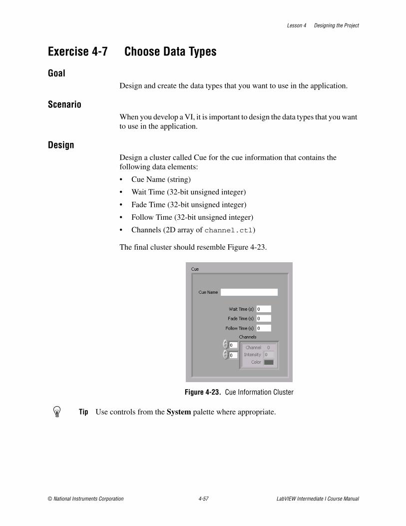
Lesson 4 Designing the Project
© National Instruments Corporation 4-57 LabVIEW Intermediate I Course Manual
Exercise 4-7 Choose Data Types
GoalDesign and create the data types that you want to use in the application.
ScenarioWhen you develop a VI, it is important to design the data types that you want to use in the application.
DesignDesign a cluster called Cue for the cue information that contains the following data elements:
• Cue Name (string)
• Wait Time (32-bit unsigned integer)
• Fade Time (32-bit unsigned integer)
• Follow Time (32-bit unsigned integer)
• Channels (2D array of channel.ctl)
The final cluster should resemble Figure 4-23.
Figure 4-23. Cue Information Cluster
Tip Use controls from the System palette where appropriate.
Lesson 4 Designing the Project
LabVIEW Intermediate I Course Manual 4-58 ni.com
Implementation1. Add tlc_Cue_Information.ctl to the Controls folder in the
TLC project.
❑ Right-click the Controls folder in the TLC project tree and select Add File from the shortcut menu.
❑ Navigate to the C:\Exercises\LabVIEW Intermediate I\Course Project\Controls directory, select tlc_Cue_Information.ctl and click the Add File button to add the file.
2. Open the control.
3. Verify that the Type Def. Status pull-down menu is set to Type Def..
4. Create the Cue Name, Wait Time, Fade Time, and Follow Time controls as described in the Design section. Use the System palette to create the controls. Place the controls inside the cluster.
❑ Place a system string control in the cluster and name the control Cue Name.
❑ Place a system numeric control in the cluster and name the numeric Wait Time (s).
❑ Right-click the numeric and select Representation»Unsigned Long (U32) from the shortcut menu.
❑ Place two copies of the Wait Time (s) control inside the cluster. Name one Fade Time (s) and name one Follow Time (s).
5. Create the Channel 2D array shell. Turn off index display for the array.
❑ Place an array from the Modern palette inside the cluster and name the array Channels.
❑ Right-click the array shell and select Add Dimension from the shortcut menu to make the array 2D.
❑ Right-click the array shell and select Visible Items»Index Display to turn off index display.
6. Add the channel.ctl file located in the C:\Exercises\LabVIEW Intermediate I\Course Project\Controls directory to the Controls folder of the TLC project.

Lesson 4 Designing the Project
© National Instruments Corporation 4-59 LabVIEW Intermediate I Course Manual
7. Click and drag channel.ctl from the Project Explorer window into the Channel array shell that you created in step 5.
8. Save the completed control.
9. Close the Control Editor and any open VIs. Do not save changes.
End of Exercise 4-7
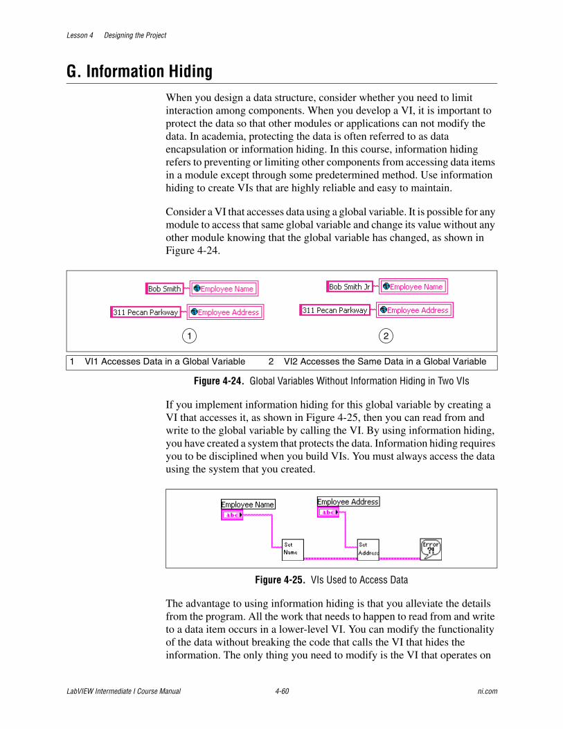
Lesson 4 Designing the Project
LabVIEW Intermediate I Course Manual 4-60 ni.com
G. Information HidingWhen you design a data structure, consider whether you need to limit interaction among components. When you develop a VI, it is important to protect the data so that other modules or applications can not modify the data. In academia, protecting the data is often referred to as data encapsulation or information hiding. In this course, information hiding refers to preventing or limiting other components from accessing data items in a module except through some predetermined method. Use information hiding to create VIs that are highly reliable and easy to maintain.
Consider a VI that accesses data using a global variable. It is possible for any module to access that same global variable and change its value without any other module knowing that the global variable has changed, as shown in Figure 4-24.
Figure 4-24. Global Variables Without Information Hiding in Two VIs
If you implement information hiding for this global variable by creating a VI that accesses it, as shown in Figure 4-25, then you can read from and write to the global variable by calling the VI. By using information hiding, you have created a system that protects the data. Information hiding requires you to be disciplined when you build VIs. You must always access the data using the system that you created.
Figure 4-25. VIs Used to Access Data
The advantage to using information hiding is that you alleviate the details from the program. All the work that needs to happen to read from and write to a data item occurs in a lower-level VI. You can modify the functionality of the data without breaking the code that calls the VI that hides the information. The only thing you need to modify is the VI that operates on
1 VI1 Accesses Data in a Global Variable 2 VI2 Accesses the Same Data in a Global Variable
1 2
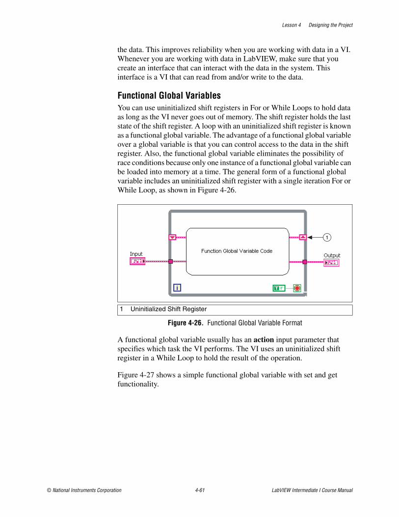
Lesson 4 Designing the Project
© National Instruments Corporation 4-61 LabVIEW Intermediate I Course Manual
the data. This improves reliability when you are working with data in a VI. Whenever you are working with data in LabVIEW, make sure that you create an interface that can interact with the data in the system. This interface is a VI that can read from and/or write to the data.
Functional Global VariablesYou can use uninitialized shift registers in For or While Loops to hold data as long as the VI never goes out of memory. The shift register holds the last state of the shift register. A loop with an uninitialized shift register is known as a functional global variable. The advantage of a functional global variable over a global variable is that you can control access to the data in the shift register. Also, the functional global variable eliminates the possibility of race conditions because only one instance of a functional global variable can be loaded into memory at a time. The general form of a functional global variable includes an uninitialized shift register with a single iteration For or While Loop, as shown in Figure 4-26.
Figure 4-26. Functional Global Variable Format
A functional global variable usually has an action input parameter that specifies which task the VI performs. The VI uses an uninitialized shift register in a While Loop to hold the result of the operation.
Figure 4-27 shows a simple functional global variable with set and get functionality.
1 Uninitialized Shift Register
1
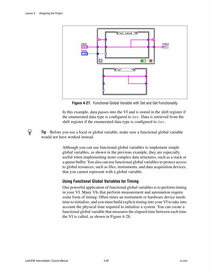
Lesson 4 Designing the Project
LabVIEW Intermediate I Course Manual 4-62 ni.com
Figure 4-27. Functional Global Variable with Set and Get Functionality
In this example, data passes into the VI and is stored in the shift register if the enumerated data type is configured to Set. Data is retrieved from the shift register if the enumerated data type is configured to Get.
Tip Before you use a local or global variable, make sure a functional global variable would not have worked instead.
Although you can use functional global variables to implement simple global variables, as shown in the previous example, they are especially useful when implementing more complex data structures, such as a stack or a queue buffer. You also can use functional global variables to protect access to global resources, such as files, instruments, and data acquisition devices, that you cannot represent with a global variable.
Using Functional Global Variables for TimingOne powerful application of functional global variables is to perform timing in your VI. Many VIs that perform measurement and automation require some form of timing. Often times an instrument or hardware device needs time to initialize, and you must build explicit timing into your VI to take into account the physical time required to initialize a system. You can create a functional global variable that measures the elapsed time between each time the VI is called, as shown in Figure 4-28.
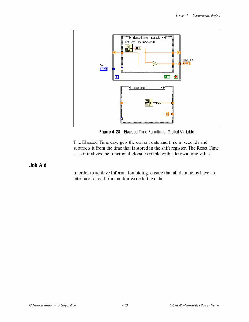
Lesson 4 Designing the Project
© National Instruments Corporation 4-63 LabVIEW Intermediate I Course Manual
Figure 4-28. Elapsed Time Functional Global Variable
The Elapsed Time case gets the current date and time in seconds and subtracts it from the time that is stored in the shift register. The Reset Time case initializes the functional global variable with a known time value.
Job AidIn order to achieve information hiding, ensure that all data items have an interface to read from and/or write to the data.
Lesson 4 Designing the Project
LabVIEW Intermediate I Course Manual 4-64 ni.com
Exercise 4-8 Information Hiding
GoalDesign a VI that provides an interface to the data.
ScenarioBuild a VI that uses a functional global variable to provide an interface to the Cue data type you created in Exercise 4-7. The functional global variable provides a safe way to access the data that the application needs.
DesignTo provide an interface to the data in the Cue data type, you need to create a VI that can access the Cue data type. Create a functional global variable to access the data.
The functional global variable implements the following functions:
• Initialize
• Add Cue
• Delete Cue
• Get Cue Values
• Set Cue Values
• Swap
• Get Number of Cues
• Get Empty Cue
Implementation1. Open the TLC project if it is not already open.
2. Create a Cue folder in the Modules folder of the TLC project.
❑ Right-click the Modules folder in the Project Explorer window and select New»Folder from the shortcut menu.
❑ Name the folder Cue.
3. Add tlc_Cue Module.vi located in the C:\Exercises\LabVIEW Intermediate I\Course Project\Modules\Cue directory to the Cue folder.
❑ Right-click the Cue folder in the Project Explorer window and select Add File from the shortcut menu
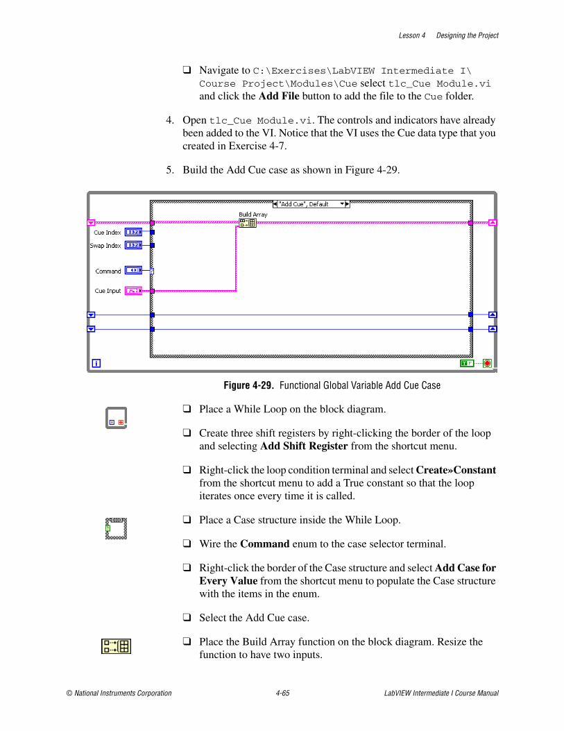
Lesson 4 Designing the Project
© National Instruments Corporation 4-65 LabVIEW Intermediate I Course Manual
❑ Navigate to C:\Exercises\LabVIEW Intermediate I\Course Project\Modules\Cue select tlc_Cue Module.vi and click the Add File button to add the file to the Cue folder.
4. Open tlc_Cue Module.vi. The controls and indicators have already been added to the VI. Notice that the VI uses the Cue data type that you created in Exercise 4-7.
5. Build the Add Cue case as shown in Figure 4-29.
Figure 4-29. Functional Global Variable Add Cue Case
❑ Place a While Loop on the block diagram.
❑ Create three shift registers by right-clicking the border of the loop and selecting Add Shift Register from the shortcut menu.
❑ Right-click the loop condition terminal and select Create»Constant from the shortcut menu to add a True constant so that the loop iterates once every time it is called.
❑ Place a Case structure inside the While Loop.
❑ Wire the Command enum to the case selector terminal.
❑ Right-click the border of the Case structure and select Add Case for Every Value from the shortcut menu to populate the Case structure with the items in the enum.
❑ Select the Add Cue case.
❑ Place the Build Array function on the block diagram. Resize the function to have two inputs.
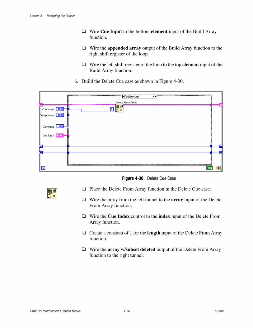
Lesson 4 Designing the Project
LabVIEW Intermediate I Course Manual 4-66 ni.com
❑ Wire Cue Input to the bottom element input of the Build Array function.
❑ Wire the appended array output of the Build Array function to the right shift register of the loop.
❑ Wire the left shift register of the loop to the top element input of the Build Array function.
6. Build the Delete Cue case as shown in Figure 4-30.
Figure 4-30. Delete Cue Case
❑ Place the Delete From Array function in the Delete Cue case.
❑ Wire the array from the left tunnel to the array input of the Delete From Array function.
❑ Wire the Cue Index control to the index input of the Delete From Array function.
❑ Create a constant of 1 for the length input of the Delete From Array function.
❑ Wire the array w/subset deleted output of the Delete From Array function to the right tunnel.
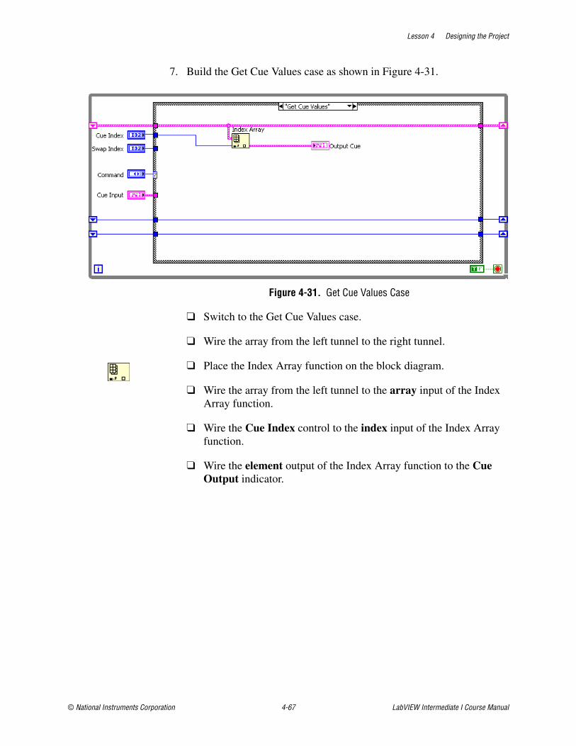
Lesson 4 Designing the Project
© National Instruments Corporation 4-67 LabVIEW Intermediate I Course Manual
7. Build the Get Cue Values case as shown in Figure 4-31.
Figure 4-31. Get Cue Values Case
❑ Switch to the Get Cue Values case.
❑ Wire the array from the left tunnel to the right tunnel.
❑ Place the Index Array function on the block diagram.
❑ Wire the array from the left tunnel to the array input of the Index Array function.
❑ Wire the Cue Index control to the index input of the Index Array function.
❑ Wire the element output of the Index Array function to the Cue Output indicator.
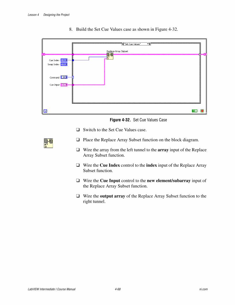
Lesson 4 Designing the Project
LabVIEW Intermediate I Course Manual 4-68 ni.com
8. Build the Set Cue Values case as shown in Figure 4-32.
Figure 4-32. Set Cue Values Case
❑ Switch to the Set Cue Values case.
❑ Place the Replace Array Subset function on the block diagram.
❑ Wire the array from the left tunnel to the array input of the Replace Array Subset function.
❑ Wire the Cue Index control to the index input of the Replace Array Subset function.
❑ Wire the Cue Input control to the new element/subarray input of the Replace Array Subset function.
❑ Wire the output array of the Replace Array Subset function to the right tunnel.
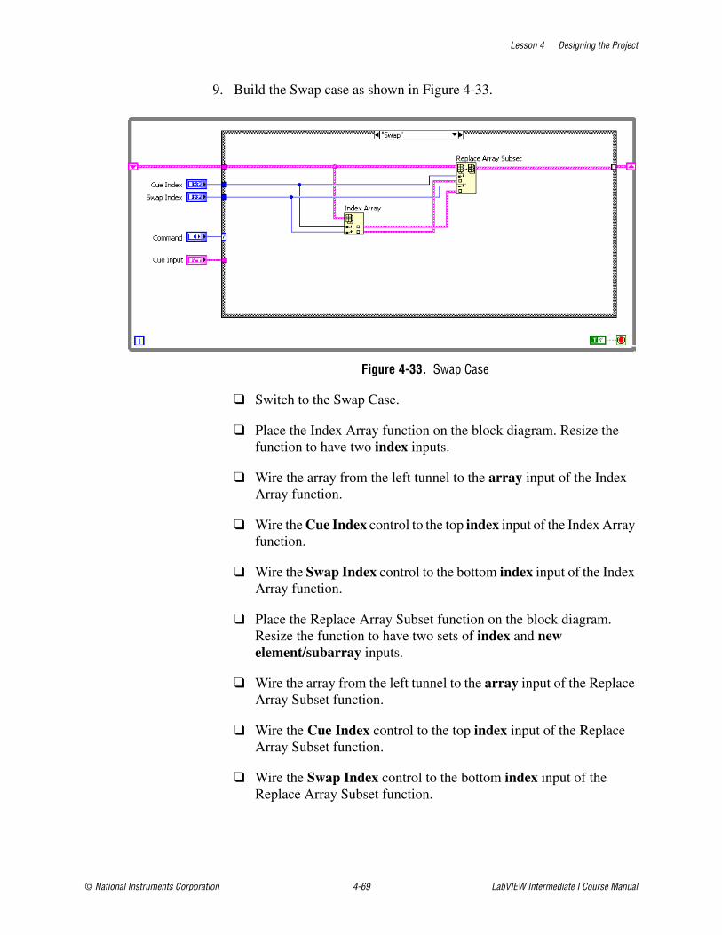
Lesson 4 Designing the Project
© National Instruments Corporation 4-69 LabVIEW Intermediate I Course Manual
9. Build the Swap case as shown in Figure 4-33.
Figure 4-33. Swap Case
❑ Switch to the Swap Case.
❑ Place the Index Array function on the block diagram. Resize the function to have two index inputs.
❑ Wire the array from the left tunnel to the array input of the Index Array function.
❑ Wire the Cue Index control to the top index input of the Index Array function.
❑ Wire the Swap Index control to the bottom index input of the Index Array function.
❑ Place the Replace Array Subset function on the block diagram. Resize the function to have two sets of index and new element/subarray inputs.
❑ Wire the array from the left tunnel to the array input of the Replace Array Subset function.
❑ Wire the Cue Index control to the top index input of the Replace Array Subset function.
❑ Wire the Swap Index control to the bottom index input of the Replace Array Subset function.
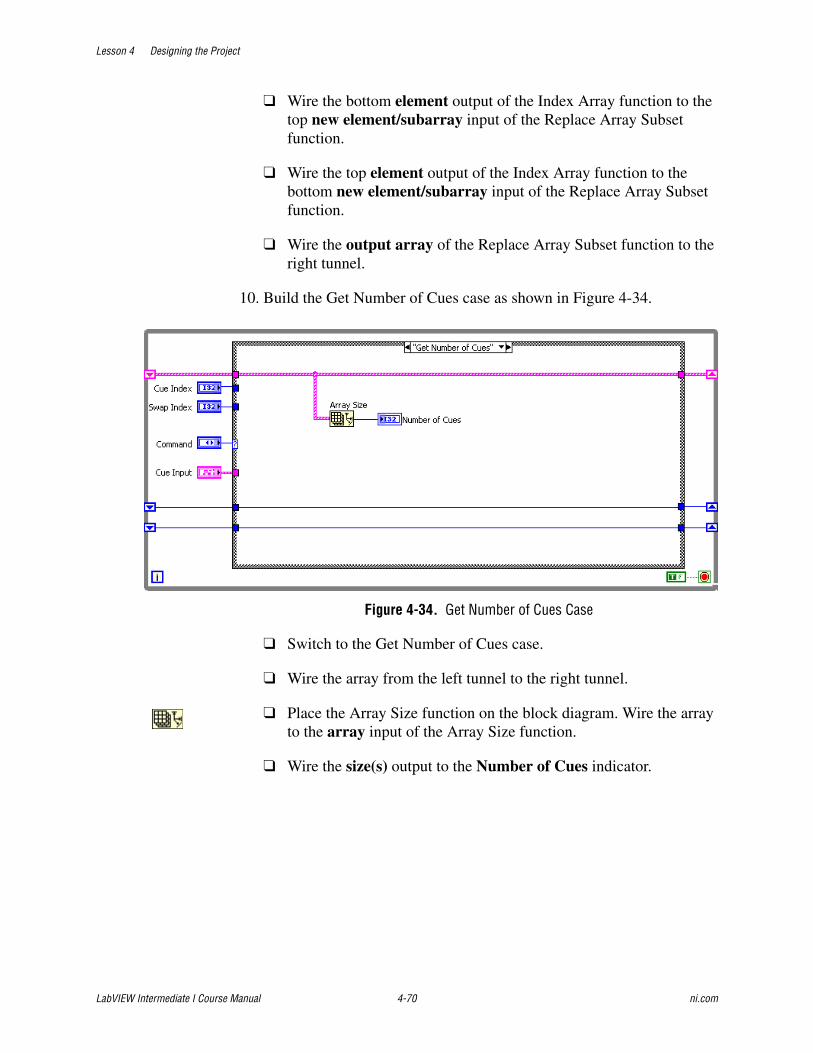
Lesson 4 Designing the Project
LabVIEW Intermediate I Course Manual 4-70 ni.com
❑ Wire the bottom element output of the Index Array function to the top new element/subarray input of the Replace Array Subset function.
❑ Wire the top element output of the Index Array function to the bottom new element/subarray input of the Replace Array Subset function.
❑ Wire the output array of the Replace Array Subset function to the right tunnel.
10. Build the Get Number of Cues case as shown in Figure 4-34.
Figure 4-34. Get Number of Cues Case
❑ Switch to the Get Number of Cues case.
❑ Wire the array from the left tunnel to the right tunnel.
❑ Place the Array Size function on the block diagram. Wire the array to the array input of the Array Size function.
❑ Wire the size(s) output to the Number of Cues indicator.
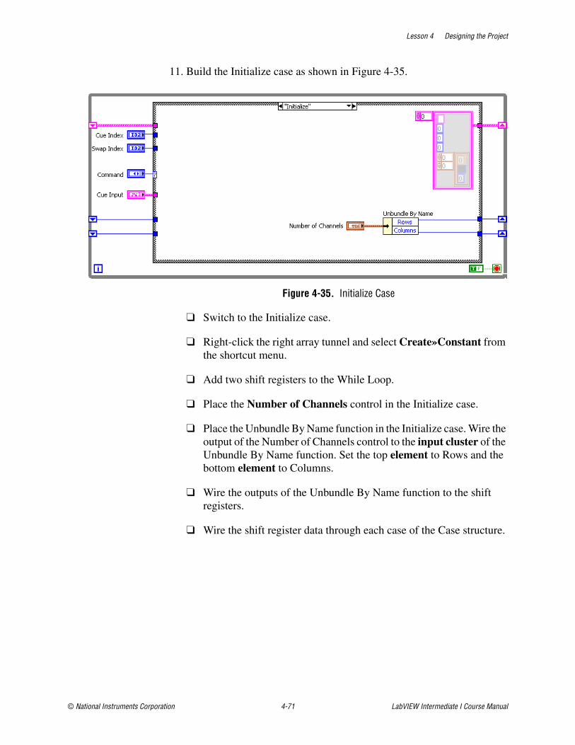
Lesson 4 Designing the Project
© National Instruments Corporation 4-71 LabVIEW Intermediate I Course Manual
11. Build the Initialize case as shown in Figure 4-35.
Figure 4-35. Initialize Case
❑ Switch to the Initialize case.
❑ Right-click the right array tunnel and select Create»Constant from the shortcut menu.
❑ Add two shift registers to the While Loop.
❑ Place the Number of Channels control in the Initialize case.
❑ Place the Unbundle By Name function in the Initialize case. Wire the output of the Number of Channels control to the input cluster of the Unbundle By Name function. Set the top element to Rows and the bottom element to Columns.
❑ Wire the outputs of the Unbundle By Name function to the shift registers.
❑ Wire the shift register data through each case of the Case structure.
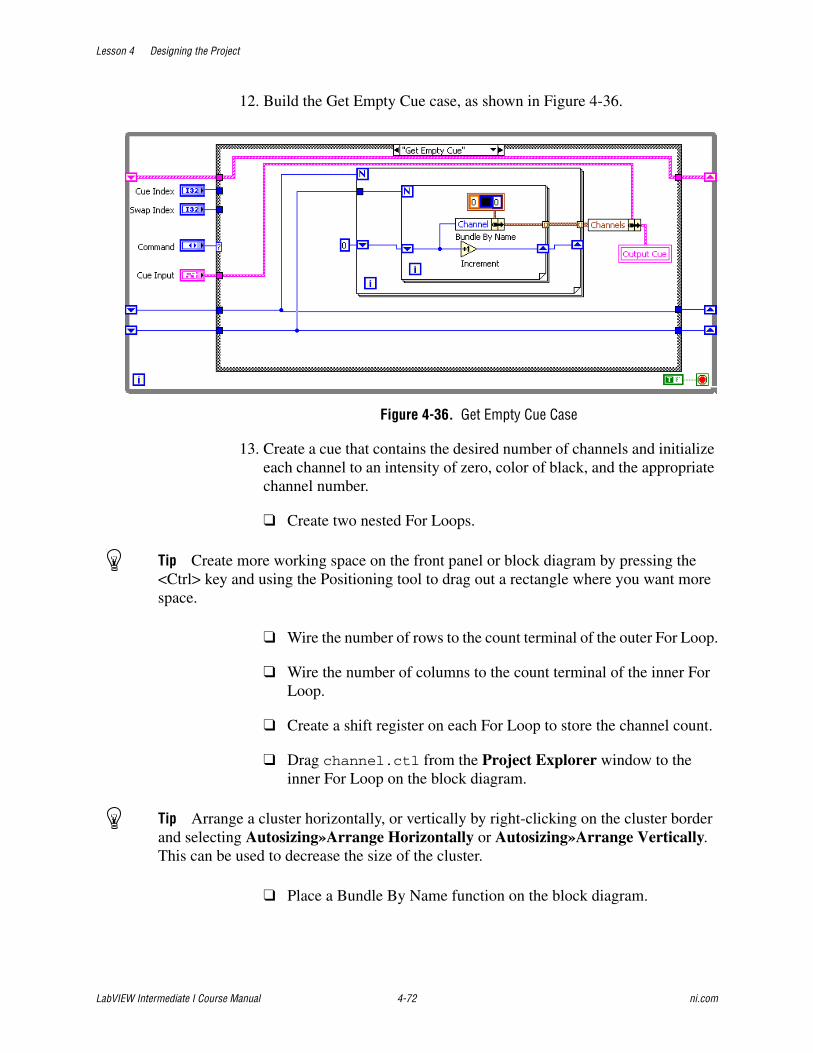
Lesson 4 Designing the Project
LabVIEW Intermediate I Course Manual 4-72 ni.com
12. Build the Get Empty Cue case, as shown in Figure 4-36.
Figure 4-36. Get Empty Cue Case
13. Create a cue that contains the desired number of channels and initialize each channel to an intensity of zero, color of black, and the appropriate channel number.
❑ Create two nested For Loops.
Tip Create more working space on the front panel or block diagram by pressing the <Ctrl> key and using the Positioning tool to drag out a rectangle where you want more space.
❑ Wire the number of rows to the count terminal of the outer For Loop.
❑ Wire the number of columns to the count terminal of the inner For Loop.
❑ Create a shift register on each For Loop to store the channel count.
❑ Drag channel.ctl from the Project Explorer window to the inner For Loop on the block diagram.
Tip Arrange a cluster horizontally, or vertically by right-clicking on the cluster border and selecting Autosizing»Arrange Horizontally or Autosizing»Arrange Vertically. This can be used to decrease the size of the cluster.
❑ Place a Bundle By Name function on the block diagram.
Lesson 4 Designing the Project
© National Instruments Corporation 4-73 LabVIEW Intermediate I Course Manual
❑ Wire channel.ctl to the Bundle By Name function and set the cluster element to Channel.
❑ Create a I32 constant on the left shift register of the outer For Loop and set the constant to 0.
❑ Wire the output of the shift registers to the Channel input of the Bundle By Name function.
❑ Wire the output cluster of the Bundle By Name function to auto indexed tunnels on each For Loop.
❑ Place the Increment function in the inner For Loop.
❑ Wire the left hand shift register to the input of the Increment function, and wire the output of the Increment function to the right hand shift register.
❑ Place a Bundle By Name function on the block diagram.
❑ Wire the Cue Input control to the input cluster of the Bundle By Name function.
❑ Select Channel on the Bundle By Name function.
❑ Wire the output of the auto indexed tunnels to the Channel input on the Bundle By Name function.
❑ Create a local variable for the Cue Output by right-clicking on the Cue Output control on the front panel and selecting Create»Local Variable.
❑ Wire the output cluster of the Bundle By Name function to the local variable.
14. Save the VI.
This VI provides controlled access to the data stored in the cue. With this type of VI, the data is protected.
Lesson 4 Designing the Project
LabVIEW Intermediate I Course Manual 4-74 ni.com
TestingTest the VI to verify its operation.
1. Set the following front panel controls:
❑ Enum = Initialize
❑ Rows = 4
❑ Columns = 8
2. Run the VI.
3. Set the following front panel controls:
❑ Enum = Get Empty Cue
4. Run the VI.
5. Verify that the Cue Output contains a 32 element Channel array. The array should contain 32 elements because you specified four rows and eight columns. Show the index display on the array to view the elements.
6. Set the following front panel controls:
❑ Enum = Add Cue
❑ Cue Input = Place dummy data in the Wait Time(s), Fade Time(s), and Follow Time(s) controls.
7. Run the VI.
8. Set the following front panel controls:
❑ Enum = Get Number of Cues
9. Run the VI.
10. Verify that the Number of Cues indicator displays 1.
11. Set the following front panel controls:
❑ Enum = Get Cue Values
❑ Cue Index = 0
12. Run the VI.

Lesson 4 Designing the Project
© National Instruments Corporation 4-75 LabVIEW Intermediate I Course Manual
13. Verify that the Cue Output matches the information that you placed in step 6.
14. Test the Swap functionality by adding another Cue, then calling the module with the enum set to Swap. Swap the two cues that you have entered.
End of Exercise 4-8
Lesson 4 Designing the Project
LabVIEW Intermediate I Course Manual 4-76 ni.com
H. Designing Error Handling StrategiesNo matter how confident you are in the VI you create, you cannot predict every problem a user can encounter. Without a mechanism to check for errors, you know only that the VI does not work properly. Error checking tells you why and where errors occur.
During the software design process, you must define a strategy for handling errors. There are three primary strategies you can use to handle errors in LabVIEW.
• You can design a proactive system that catches potential errors. For example, you might need to catch any problems in a configuration before the system passes the configuration to a data acquisition driver. The system can prevent the data acquisition driver from executing if there are errors in the configuration.
• You can design corrective error processing that tries to determine the error and fix the error. This allows each module to implement error correcting code. For example, you could develop a Read File I/O VI to fix errors that occur in the Open/Create/Replace File VI.
• You can design a system that reports errors to the user. If an error occurs, the individual modules do not execute, and the system notifies the user what error occurred.
When creating software, you should develop separate error handling code for two phases of the process—development and deployment. During development, the error handling code should be noticeable and should clearly indicate where errors occur. This helps you determine where any bugs might exist in a VI. During deployment, however, you want the error handling system to be unobtrusive to the user. This error handling system should allow a clean exit and provide clear prompts to the user.
When you design the error handling strategy, consider how the system should respond based on the severity of the error. If the error is only a warning, it is not necessary to completely stop the system when the error occurs. For example, consider a File dialog box that contains a Cancel button the user can click to cancel the selection of a file. If the user clicks the Cancel button, the entire software system should not stop. It is preferable to log this type of error as a warning. An exception error indicates that something drastic has occurred in the system, such as a file logging system that runs out of storage space. Exception errors should prevent the rest of the system from operating.

Lesson 4 Designing the Project
© National Instruments Corporation 4-77 LabVIEW Intermediate I Course Manual
Checking for ErrorsWhen you perform any kind of input and output (I/O), consider the possibility that errors might occur. Almost all I/O functions return error information. Include error checking in VIs, especially for I/O operations (file, serial, instrumentation, data acquisition, and communication), and provide a mechanism to handle errors appropriately.
Error Handling
You can choose other error handling methods. For example, if an I/O VI on the block diagram times out, you might not want the entire application to stop and display an error dialog box. You also might want the VI to retry for a certain period of time. In LabVIEW, you can make these error handling decisions on the block diagram of the VI.
Use the LabVIEW error handling VIs and functions on the Dialog & User Interface palette and the error in and error out parameters of most VIs and functions to manage errors. For example, if LabVIEW encounters an error, you can display the error message in different kinds of dialog boxes. Use error handling in conjunction with the debugging tools to find and manage errors.
VIs and functions return errors in one of two ways—with numeric error codes or with an error cluster. Typically, functions use numeric error codes, and VIs use an error cluster, usually with error inputs and outputs.
Error handling in LabVIEW follows the dataflow model. Just as data values flow through a VI, so can error information. Wire the error information from the beginning of the VI to the end. Include an error handler VI at the end of the VI to determine if the VI ran without errors. Use the error in and error out clusters in each VI you use or build to pass the error information through the VI.
As the VI runs, LabVIEW tests for errors at each execution node. If LabVIEW does not find any errors, the node executes normally. If LabVIEW detects an error, the node passes the error to the next node without executing that part of the code. The next node does the same thing, and so on. At the end of the execution flow, LabVIEW reports the error.

Lesson 4 Designing the Project
LabVIEW Intermediate I Course Manual 4-78 ni.com
Error ClustersThe error in and error out clusters include the following components of information:
• status is a Boolean value that reports TRUE if an error occurred.
• code is a 32-bit signed integer that identifies the error numerically. A nonzero error code coupled with a status of FALSE signals a warning rather than a error.
• source is a string that identifies where the error occurred.
Error CodesYou can create custom error messages that are meaningful for your own VIs. Determine where possible errors can occur in the VI, and define error codes and messages for those errors. National Instruments recommends that you use the General Error Handler VI to define custom error codes in the range of 5000 to 9999 and –8999 to –8000. However, you also can define custom error codes in the same range using the Error Code File Editor dialog box. Use this method if you want to use the same custom error codes with several VIs or if you want to distribute custom error codes with an application or shared library. If you want to distribute the custom error codes with an application or shared library, you must distribute the error code text files.
Complete the following steps to define custom error codes using the Error Code File Editor.
1. Select Tools»Advanced»Edit Error Codes to launch the Error Code File Editor.
2. Click the New button to create an error codes file or click the Open button to browse to an existing error codes file.
3. Enter comments about the error codes file in the Comments about this file text box.
4. Click the Add button to add an error code and description to the error codes file.
5. Select and edit an error code description using the Current Error Code and Description controls.
6. When you are done editing the error codes file, select File»Save to save the error codes file in the labview\user.lib\errors directory.
You also can define custom error codes in the same range by creating an XML-based text file. You must name the text file xxx-errors.txt, where xxx is a name that you supply. The xxx-errors.txt file must use the following syntax exactly, including capitalization, spacing, and so on. You supply the italic text:
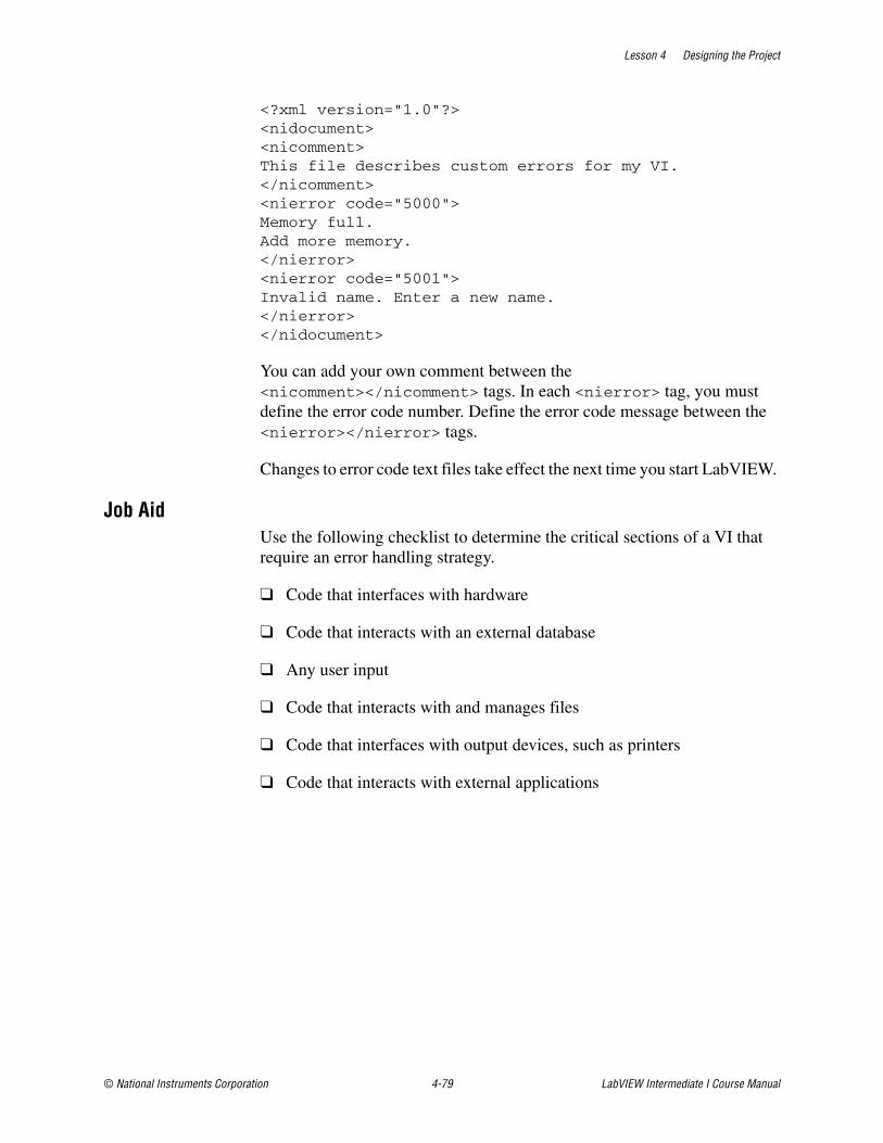
Lesson 4 Designing the Project
© National Instruments Corporation 4-79 LabVIEW Intermediate I Course Manual
<?xml version="1.0"?> <nidocument> <nicomment> This file describes custom errors for my VI. </nicomment> <nierror code="5000"> Memory full. Add more memory. </nierror> <nierror code="5001"> Invalid name. Enter a new name.</nierror></nidocument>
You can add your own comment between the <nicomment></nicomment> tags. In each <nierror> tag, you must define the error code number. Define the error code message between the <nierror></nierror> tags.
Changes to error code text files take effect the next time you start LabVIEW.
Job AidUse the following checklist to determine the critical sections of a VI that require an error handling strategy.
❑ Code that interfaces with hardware
❑ Code that interacts with an external database
❑ Any user input
❑ Code that interacts with and manages files
❑ Code that interfaces with output devices, such as printers
❑ Code that interacts with external applications
Lesson 4 Designing the Project
LabVIEW Intermediate I Course Manual 4-80 ni.com
Exercise 4-9 Design Error Handling Strategy
GoalDevelop a strategy to handle errors in the application.
ScenarioCreating an error code that is custom to the application is easy in the LabVIEW environment. Using the error code in the application provides a detailed description of the error that occurred. You can use this information to diagnose the error and where the error occurred. Every application that contains multiple states must provide a method and strategy for handling errors.
Design
Use the LabVIEW Error Code File Editor to create the following error code, based on a possible error that can occur in the application.
Implementation1. Open the TLC project if it is not already open.
2. Open the Error Code File Editor.
❑ Select Tools»Advanced»Edit Error Codes and click the New button to create a new error code file.
3. Create the error code as specified in the Design section.
❑ Click the Add button to open the Add Error Code dialog box. LabVIEW automatically sets the New Code value to 5000 and increments it each time you click the Add button.
❑ Enter the description from the table in the Design section in the New Description text box.
❑ Click the OK button to add the error code.
4. Select File»Save As to save the error code file as tlc-errors.txt in the labview\user.lib\errors directory and close the editor.
5. Close the LabVIEW Error Code File editor.
Error Code Description
5000 Cue Data Error
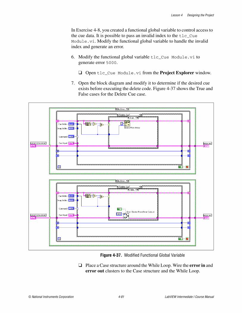
Lesson 4 Designing the Project
© National Instruments Corporation 4-81 LabVIEW Intermediate I Course Manual
In Exercise 4-8, you created a functional global variable to control access to the cue data. It is possible to pass an invalid index to the tlc_Cue Module.vi. Modify the functional global variable to handle the invalid index and generate an error.
6. Modify the functional global variable tlc_Cue Module.vi to generate error 5000.
❑ Open tlc_Cue Module.vi from the Project Explorer window.
7. Open the block diagram and modify it to determine if the desired cue exists before executing the delete code. Figure 4-37 shows the True and False cases for the Delete Cue case.
Figure 4-37. Modified Functional Global Variable
❑ Place a Case structure around the While Loop. Wire the error in and error out clusters to the Case structure and the While Loop.
Lesson 4 Designing the Project
LabVIEW Intermediate I Course Manual 4-82 ni.com
❑ Select the Delete Cue case and place a Case structure around the Delete From Array function.
❑ Place the Array Size function on the block diagram. Wire the array to the array input of the Array Size function.
❑ Place a Decrement function on the block diagram and wire it to the size(s) output of the Array Size function.
❑ Place a Greater or Equal? function on the block diagram. Wire the output of the Decrement function to the x input and wire Cue Index to the y input. Wire the output of the Greater or Equal? function to the case selector terminal.
❑ Select the False case of the Case structure and place the Error Cluster From Error Code VI on the block diagram. This VI converts an error or warning code to an error cluster. This VI is useful when you receive a return value from a DLL call or when you return user-defined error codes. Create a True constant from the show call chain? input so that when an error occurs, source includes the chain of callers from the VI that produced the error or warning to the top-level VI. Pass the error code that you defined for the cue data error (5000) to the error code (0) input of the VI.
8. Save the project and the VI.
Testing1. Restart LabVIEW to load the error code file.
2. Generate an error with the Cue Module VI.
❑ Open the TLC project.
❑ Open tlc_Cue Module.vi located in the Project Explorer window.
❑ Enter an invalid Cue Index with the Command enum set to Delete Cue.
❑ Run the VI.
3. Verify that the error explanation matches what you specified when you created the error code file.
Lesson 4 Designing the Project
© National Instruments Corporation 4-83 LabVIEW Intermediate I Course Manual
Challenge1. Modify the other cases so that a error generates when an invalid cue
index passes to the VI.
Tip For the Swap case, also include code that checks for a valid swap index.
End of Exercise 4-9
Lesson 4 Designing the Project
LabVIEW Intermediate I Course Manual 4-84 ni.com
Summary• VIs that use design patterns can be easier to read and modify.
• Use design patterns to create a scalable architecture.
• Event-driven programs usually include a loop that waits for an event to occur, executes code to respond to the event, and reiterates to wait for the next event.
• A good module hierarchy has high cohesion and low coupling.
• Choose scalars, arrays, or clusters to represent the data.
• Use information hiding to create VIs that are highly reliable and easy to maintain.
• Use custom error codes to design an error handling strategy.

Lesson 4 Designing the Project
© National Instruments Corporation 4-85 LabVIEW Intermediate I Course Manual
Notes

Lesson 4 Designing the Project
LabVIEW Intermediate I Course Manual 4-86 ni.com
Notes

© National Instruments Corporation 5-1 LabVIEW Intermediate I Course Manual
5Implementing the User Interface
In this lesson, you implement the user interface that you prototyped in Lesson 3, Designing the User Interface. This lesson describes techniques you can use in LabVIEW to improve the way you implement user interfaces. You use a structured approach to developing a VI user interface. You learn valuable techniques that improve the usability of the user interface and improve the development of the VI.
Topics
A. Implementing User Interface-Based Data TypesB. Implementing Meaningful Icons
C. Implementing Appropriate Connector Panes

Lesson 5 Implementing the User Interface
LabVIEW Intermediate I Course Manual 5-2 ni.com
A. Implementing User Interface-Based Data TypesLabVIEW uses user interface-based data types to store data. Unlike text-based programming languages, where you must declare variables, LabVIEW stores data as it flows through the VI. LabVIEW stores data in one of three ways—user interface-based (front panel) data types, block diagram constants, or shift registers. You can store data on the user interface as scalar data, arrays, or clusters. A good way to organize the data in a VI is to group the data, such as in an array or a cluster. Grouping the data improves the readability of the VI and helps reduce development time because LabVIEW includes built-in functions for handling grouped data.
Scalar DataAs described in Lesson 3, Designing the User Interface, an example of a scalar value can be a numeric value or a Boolean value. There are many ways to organize scalar data to improve the user interface and the usability of the application. The preferred method for organizing scalar data is to use a ring control or enumerated type control. These controls associate a numeric value with a text string that the user sees on the front panel or user interface.
Ring ControlsRing controls are numeric objects that associate numeric values with strings or pictures. Ring controls appear as pull-down menus that users can cycle through to make selections.
Ring controls are useful for selecting mutually exclusive items, such as trigger modes. For example, use a ring control for users to select from continuous, single, and external triggering.
When you configure the list of items for a ring control, you can assign a specific numeric value to each item. If you do not assign specific numeric values to the items, LabVIEW assigns sequential values that correspond to the order of the items in the list, starting with a value of 0 for the first item.
Enumerated Type ControlsUse enumerated type controls to give users a list of items from which to select. An enumerated type control, or enum, is similar to a text or menu ring control. However, the data type of an enumerated type control includes information about the numeric values and the string labels in the control. The data type of a ring control is numeric.
Lesson 5 Implementing the User Interface
© National Instruments Corporation 5-3 LabVIEW Intermediate I Course Manual
Enumerated Type Controls Versus Ring ControlsRing controls are useful for front panels the user interacts with where you want to programmatically change the string labels. You might want to use a ring control instead of a Boolean control because if you decide to change the control to include more than two options, you can add options easily to a ring control.
You cannot change the string labels in an enumerated type control programmatically at run time because the string labels are a part of the data type. When using enumerated type controls, always make a type definition of the control. Creating type definitions prevents you from needing to rewrite the code each time you add or remove an item from an enumerated type control.
Enumerated type controls are useful for making block diagram code easier to read because when you wire an enumerated type control to a Case structure, the string labels appear in the selector label of the Case structure.
Numeric Scalar DataWhen you use scalar data that is numeric, such as a numeric control, it is important to choose an appropriate representation for the data type. When you make a decision on the representation, you must understand and consider what type of data you want to store in the data type. Try to choose data types that provide a more accurate range for the data that you want to store. For example, if you are developing an application that generates random integers from 0 to 10, it is appropriate to select an 8-bit unsigned integer (U8) to represent the data because an 8-bit unsigned integer can represent values from 0 to 255. The representation for the data type more closely represents the data you want to store. Refer to Table 5-1 to determine the best representation for a data type.
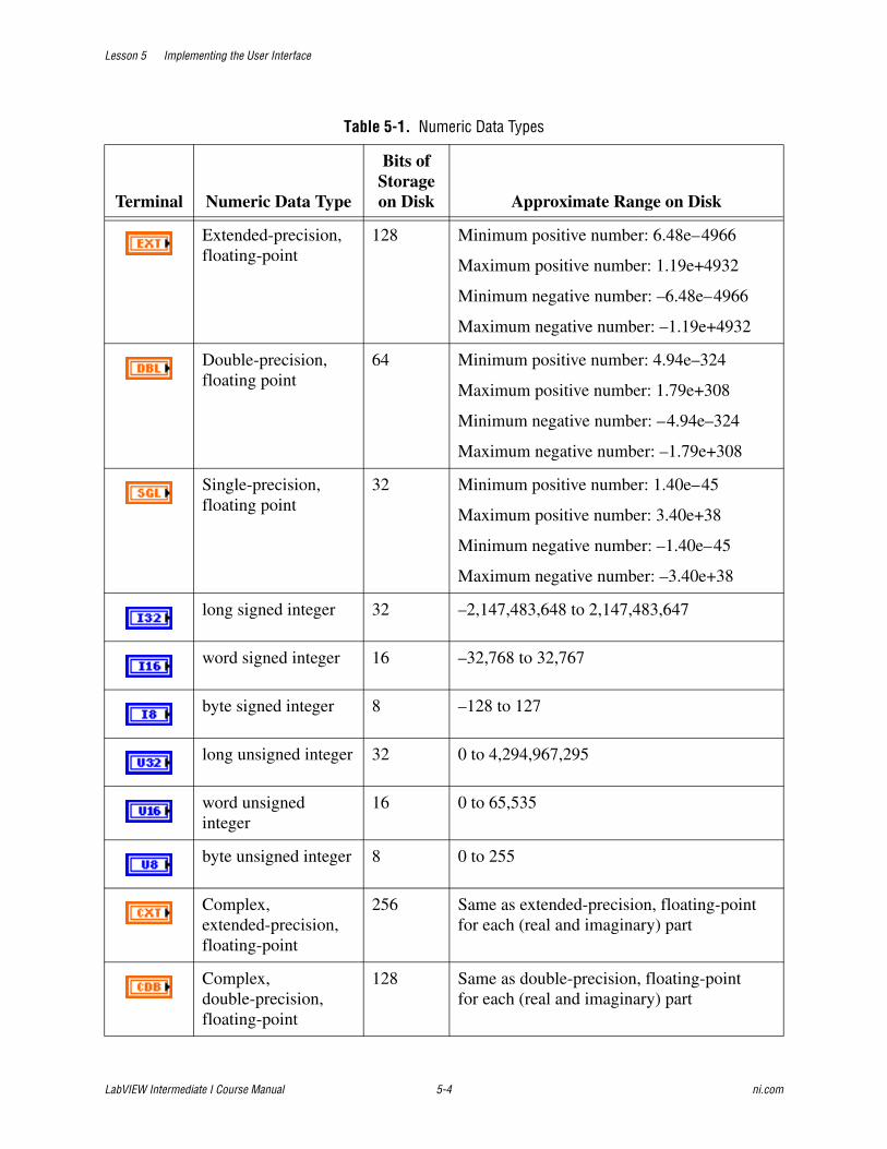
Lesson 5 Implementing the User Interface
LabVIEW Intermediate I Course Manual 5-4 ni.com
Table 5-1. Numeric Data Types
Terminal Numeric Data Type
Bits of Storage on Disk Approximate Range on Disk
Extended-precision, floating-point
128 Minimum positive number: 6.48e–4966
Maximum positive number: 1.19e+4932
Minimum negative number: –6.48e–4966
Maximum negative number: –1.19e+4932
Double-precision, floating point
64 Minimum positive number: 4.94e–324
Maximum positive number: 1.79e+308
Minimum negative number: –4.94e–324
Maximum negative number: –1.79e+308
Single-precision, floating point
32 Minimum positive number: 1.40e–45
Maximum positive number: 3.40e+38
Minimum negative number: –1.40e–45
Maximum negative number: –3.40e+38
long signed integer 32 –2,147,483,648 to 2,147,483,647
word signed integer 16 –32,768 to 32,767
byte signed integer 8 –128 to 127
long unsigned integer 32 0 to 4,294,967,295
word unsigned integer
16 0 to 65,535
byte unsigned integer 8 0 to 255
Complex, extended-precision, floating-point
256 Same as extended-precision, floating-point for each (real and imaginary) part
Complex, double-precision, floating-point
128 Same as double-precision, floating-point for each (real and imaginary) part
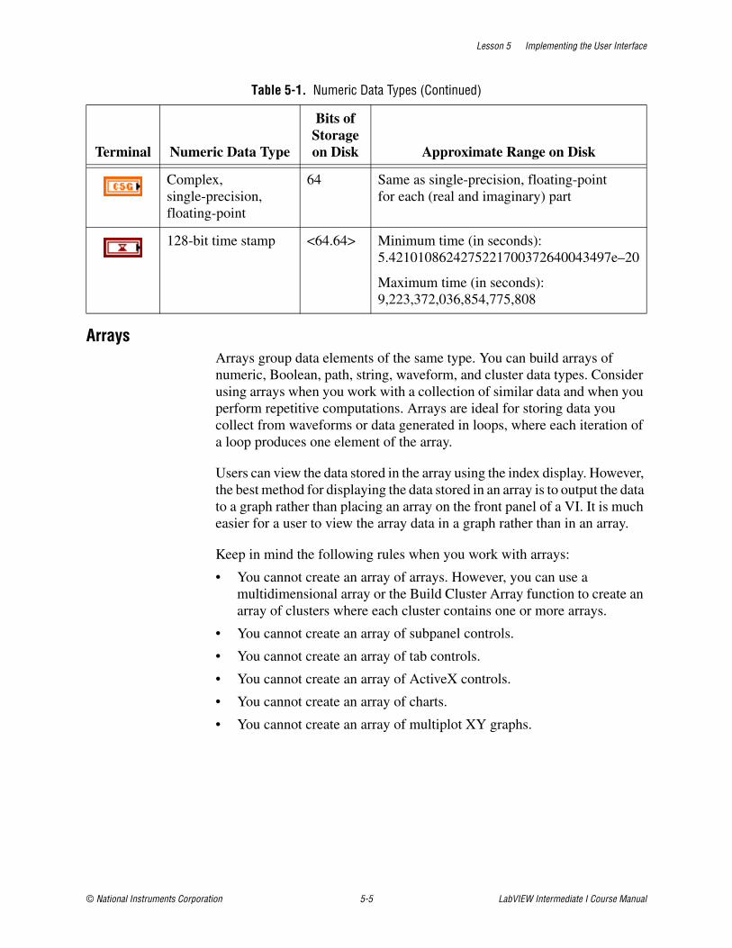
Lesson 5 Implementing the User Interface
© National Instruments Corporation 5-5 LabVIEW Intermediate I Course Manual
ArraysArrays group data elements of the same type. You can build arrays of numeric, Boolean, path, string, waveform, and cluster data types. Consider using arrays when you work with a collection of similar data and when you perform repetitive computations. Arrays are ideal for storing data you collect from waveforms or data generated in loops, where each iteration of a loop produces one element of the array.
Users can view the data stored in the array using the index display. However, the best method for displaying the data stored in an array is to output the data to a graph rather than placing an array on the front panel of a VI. It is much easier for a user to view the array data in a graph rather than in an array.
Keep in mind the following rules when you work with arrays:
• You cannot create an array of arrays. However, you can use a multidimensional array or the Build Cluster Array function to create an array of clusters where each cluster contains one or more arrays.
• You cannot create an array of subpanel controls.
• You cannot create an array of tab controls.
• You cannot create an array of ActiveX controls.
• You cannot create an array of charts.
• You cannot create an array of multiplot XY graphs.
Complex, single-precision, floating-point
64 Same as single-precision, floating-point for each (real and imaginary) part
128-bit time stamp <64.64> Minimum time (in seconds): 5.4210108624275221700372640043497e–20
Maximum time (in seconds): 9,223,372,036,854,775,808
Table 5-1. Numeric Data Types (Continued)
Terminal Numeric Data Type
Bits of Storage on Disk Approximate Range on Disk
Lesson 5 Implementing the User Interface
LabVIEW Intermediate I Course Manual 5-6 ni.com
ClustersClusters group data elements of mixed types, such as a bundle of wires, as in a telephone cable, where each wire in the cable represents a different element in the cluster. Using clusters to store data provides the following advantages:
• Clusters eliminate wire clutter on the block diagram and reduce the number of connector pane terminals a subVI uses.
• Clusters allow you to create specific, organized data objects.
Clusters are valuable tools for creating readable, maintainable VIs. You can create clusters that include any data type you choose. When you create a cluster, you should always create a type definition of the cluster so you can add new data elements to the cluster. Creating a cluster with a type definition helps make your data structures and your VIs more scalable, readable, and maintainable.
Always use the Bundle By Name and Unbundle By Name functions with clusters in your VIs. The Bundle By Name and Unbundle By Name functions help make your block diagram more readable because you can identify the data that you are placing in or using from the cluster. Also, these functions do not require you to maintain cluster order. By contrast, the Bundle and Unbundle functions are dependent on the order of items in the cluster, which can cause problems if you have similar data types in a cluster and you do not know the cluster order. The Bundle By Name and Unbundle By Name functions display the owned labels of the items in the cluster on the function terminals.
Lesson 5 Implementing the User Interface
© National Instruments Corporation 5-7 LabVIEW Intermediate I Course Manual
Job AidUse the following checklist to help develop user interface-based data structures.
❑ Use a ring control to programmatically change the string labels in the control.
❑ Use a ring control instead of a Boolean control to improve the scalability of a VI.
❑ Use an enumerated type control to improve block diagram readability. When you wire an enumerated type control to a Case structure, the Case structure displays the values of the enumerated type control in the case selector.
❑ Use arrays to store data of the same type, but use a graph to display array data.
❑ Use clusters to eliminate wire clutter and create your own custom data types.
❑ Always use the Unbundle By Name and Bundle By Name functions for programmatic control of cluster data.
❑ Always create a type definition for clusters, ring controls, and enumerated type controls.
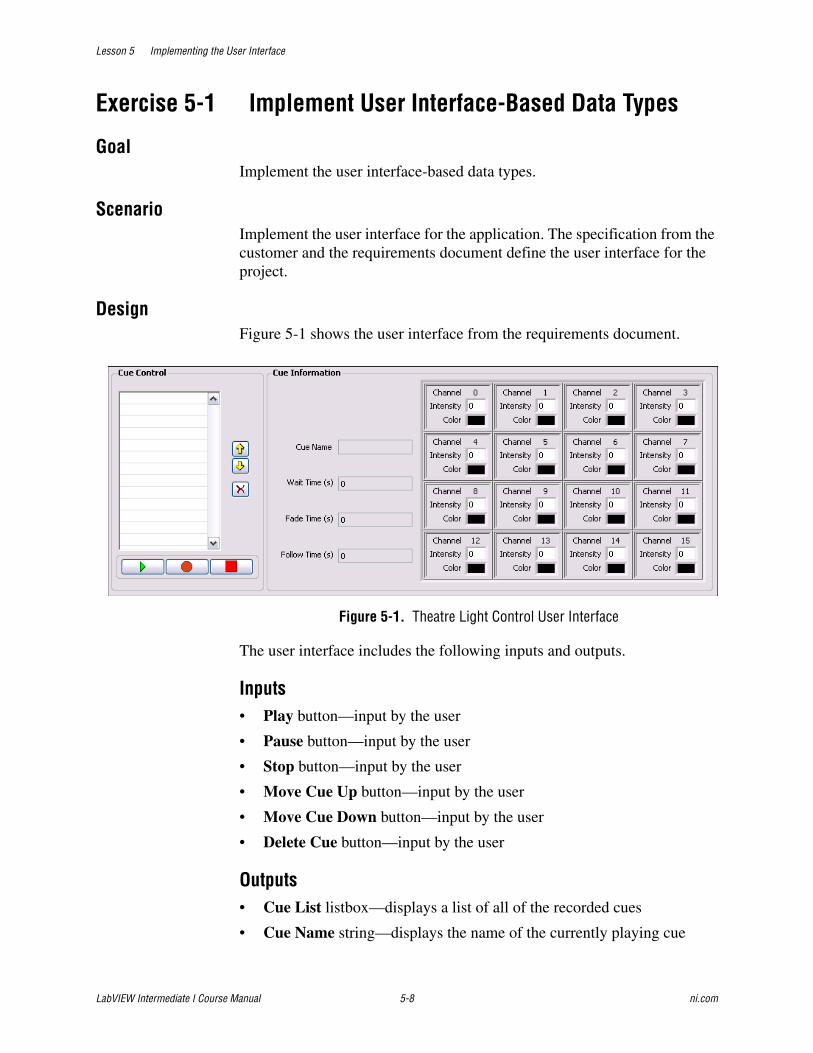
Lesson 5 Implementing the User Interface
LabVIEW Intermediate I Course Manual 5-8 ni.com
Exercise 5-1 Implement User Interface-Based Data Types
GoalImplement the user interface-based data types.
ScenarioImplement the user interface for the application. The specification from the customer and the requirements document define the user interface for the project.
DesignFigure 5-1 shows the user interface from the requirements document.
Figure 5-1. Theatre Light Control User Interface
The user interface includes the following inputs and outputs.
Inputs• Play button—input by the user
• Pause button—input by the user
• Stop button—input by the user
• Move Cue Up button—input by the user
• Move Cue Down button—input by the user
• Delete Cue button—input by the user
Outputs• Cue List listbox—displays a list of all of the recorded cues
• Cue Name string—displays the name of the currently playing cue
Lesson 5 Implementing the User Interface
© National Instruments Corporation 5-9 LabVIEW Intermediate I Course Manual
• Wait Time(s) numeric—displays the wait time for the currently playing cue
• Fade Time(s) numeric—displays the fade time for the currently playing cue
• Follow Time(s) numeric—displays the follow time for the currently playing cue
• Channel cluster—displays the channel number, channel intensity, and channel color for each channel
ImplementationCreate a front panel similar to the user interface shown in Figure 5-1.
1. Create a new VI based on the producer/consumer (events) design pattern template that you chose in Exercise 4-5.
❑ Select File»New from the Project Explorer window to open the New dialog box.
❑ In the New dialog box, select VI»From Template»Frameworks»Design Patterns»Producer/Consumer Design Pattern(Events) and make sure a checkmark appears in the Add to Project checkbox.
❑ Click the OK button to open the design pattern.
❑ Save the VI as TLC Main.vi in the C:\Exercises\LabVIEW Intermediate I\Course Project directory. LabVIEW automatically adds the file to the project.
2. Delete the Queue Event button and the STOP button.
3. Create the cue list.
❑ Place a system Listbox on the front panel.
❑ Change the label of the Listbox to Cue List.
4. Create a custom dialog button for the play button by placing an image decal on the dialog button.
❑ Place a system button on the front panel.
❑ Right-click the button and select Advanced»Customize from the shortcut menu to open the Control Editor.
Lesson 5 Implementing the User Interface
LabVIEW Intermediate I Course Manual 5-10 ni.com
❑ Select Edit»Import Picture from File and select play.gif located in the C:\Exercises\LabVIEW Intermediate I\Course Project\Shared\Images directory to place the image on the clipboard.
❑ Right-click the button in the Control Editor and select Import Picture from Clipboard»Decal from the shortcut menu to place the decal on the button.
❑ Right-click the button and select Visible Items»Boolean Text from the shortcut menu to hide the text on the button.
❑ Save the control as Play Button.ctl in the C:\Exercises\LabVIEW Intermediate I\Course Project\Controls directory.
❑ Select Play Button.ctl in the Project Explorer window and drag the file to the Controls folder in the Project Explorer window to place the control in the project hierarchy.
❑ Change the label of the control to Play.
❑ Close the Control Editor. When prompted, click Yes to replace the original control with the custom control.
5. Add the following custom controls to the project and the front panel:
– Record Button.ctl
– Stop Button.ctl
– Up Button.ctl
– Down Button.ctl
– Delete Button.ctl
❑ Right-click the Controls folder, select Add File from the shortcut menu and navigate to the C:\Exercises\LabVIEW Intermediate I\Course Project\Controls directory.
❑ Select the custom button controls from the previous list and click the Add File button to add the controls to the Controls folder.
Tip Hold the <Ctrl> key down while clicking on the file names to select multiple files.
❑ Click and drag the custom controls from the Project Explorer window to the front panel.
❑ Arrange the controls on the front panel.
Lesson 5 Implementing the User Interface
© National Instruments Corporation 5-11 LabVIEW Intermediate I Course Manual
❑ Hide the labels on the controls.
6. Place the typedef that contains the Cue Name, Wait Time, Fade Time, Follow Time, and array of Channels on the front panel.
❑ Drag tlc_Cue_Information.ctl from the Project Explorer window to the front panel.
❑ Resize and arrange the cluster to match the specification in Figure 5-1.
❑ Rename the cluster Cue Information.
7. Place decorations on the front panel to visibly group objects as shown in Figure 5-1.
Tip Use the System Recessed Frame decoration to create a professional looking user interface.
8. Place error in and error out clusters on the front panel to pass error data through the VI.
9. Resize the window to hide the error clusters.
10. Save the VI.
Note The Run button is broken because you deleted the Queue Event button and the Stop button. You resolve the broken run button in a later exercise.
End of Exercise 5-1

Lesson 5 Implementing the User Interface
LabVIEW Intermediate I Course Manual 5-12 ni.com
B. Implementing Meaningful IconsUse good style techniques when you create the icons and connector panes for VIs. Following icon and connector pane style techniques can help users understand the purpose of the VIs and make the VIs easier to use.
IconsCreate a meaningful icon for every VI.
The icon represents the VI on a palette and a block diagram. When subVIs have well-designed icons, developers can gain a better understanding of the subVI without the need for excessive documentation.
Use the following suggestions when creating icons.
• The LabVIEW libraries include well-designed icons that you can use as prototypes. When you do not have a picture for an icon, text is acceptable. If you localize the application, make sure you also localize the text on the icon. A good size and font choice for text icons is 8 point Small Fonts in all caps.
• Always create a black and white icon for printing purposes. Not every user has access to a color printer.
• Create a unified icon style for related VIs to help users visually understand what subVIs are associated with the top-level VI.
• Always create standard size (32 × 32 pixels) icons. VIs with smaller icons can be awkward to select and wire and might look strange when wired.
• Do not use colloquialisms when making an icon because colloquialisms are difficult to translate. Users whose native language is not English might not understand a picture that does not translate well. For example, do not represent a datalogging VI with a picture of a tree branch or a lumberjack.
Refer to the Creating an Icon topic of the LabVIEW Help for more information about creating icons.
Tip You can use the graphics available in the NI Icon Art Glossary to create icons. To access the Icon Art Glossary, visit ni.com/info and enter the info code rdglos. Each graphic in the glossary corresponds to an operation, such as aborting an I/O session or controlling the mode of an instrument.
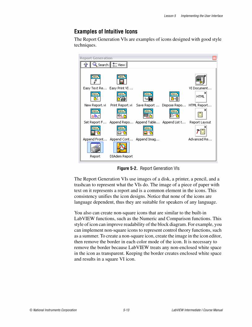
Lesson 5 Implementing the User Interface
© National Instruments Corporation 5-13 LabVIEW Intermediate I Course Manual
Examples of Intuitive IconsThe Report Generation VIs are examples of icons designed with good style techniques.
Figure 5-2. Report Generation VIs
The Report Generation VIs use images of a disk, a printer, a pencil, and a trashcan to represent what the VIs do. The image of a piece of paper with text on it represents a report and is a common element in the icons. This consistency unifies the icon designs. Notice that none of the icons are language dependent, thus they are suitable for speakers of any language.
You also can create non-square icons that are similar to the built-in LabVIEW functions, such as the Numeric and Comparison functions. This style of icon can improve readability of the block diagram. For example, you can implement non-square icons to represent control theory functions, such as a summer. To create a non-square icon, create the image in the icon editor, then remove the border in each color mode of the icon. It is necessary to remove the border because LabVIEW treats any non-enclosed white space in the icon as transparent. Keeping the border creates enclosed white space and results in a square VI icon.
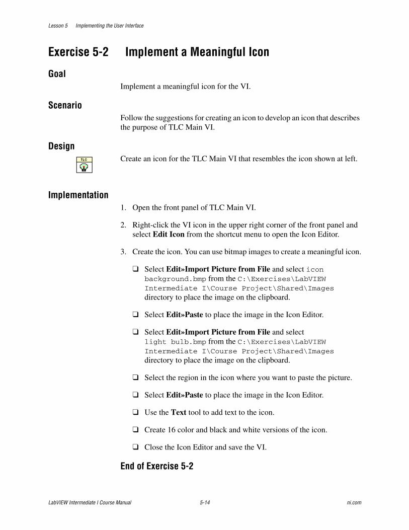
Lesson 5 Implementing the User Interface
LabVIEW Intermediate I Course Manual 5-14 ni.com
Exercise 5-2 Implement a Meaningful Icon
GoalImplement a meaningful icon for the VI.
ScenarioFollow the suggestions for creating an icon to develop an icon that describes the purpose of TLC Main VI.
DesignCreate an icon for the TLC Main VI that resembles the icon shown at left.
Implementation1. Open the front panel of TLC Main VI.
2. Right-click the VI icon in the upper right corner of the front panel and select Edit Icon from the shortcut menu to open the Icon Editor.
3. Create the icon. You can use bitmap images to create a meaningful icon.
❑ Select Edit»Import Picture from File and select icon background.bmp from the C:\Exercises\LabVIEW Intermediate I\Course Project\Shared\Images directory to place the image on the clipboard.
❑ Select Edit»Paste to place the image in the Icon Editor.
❑ Select Edit»Import Picture from File and select light bulb.bmp from the C:\Exercises\LabVIEW Intermediate I\Course Project\Shared\Images directory to place the image on the clipboard.
❑ Select the region in the icon where you want to paste the picture.
❑ Select Edit»Paste to place the image in the Icon Editor.
❑ Use the Text tool to add text to the icon.
❑ Create 16 color and black and white versions of the icon.
❑ Close the Icon Editor and save the VI.
End of Exercise 5-2
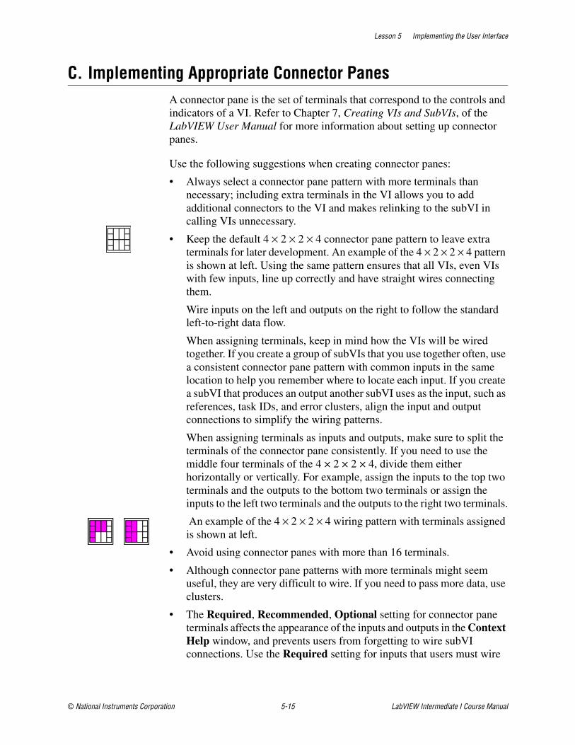
Lesson 5 Implementing the User Interface
© National Instruments Corporation 5-15 LabVIEW Intermediate I Course Manual
C. Implementing Appropriate Connector PanesA connector pane is the set of terminals that correspond to the controls and indicators of a VI. Refer to Chapter 7, Creating VIs and SubVIs, of the LabVIEW User Manual for more information about setting up connector panes.
Use the following suggestions when creating connector panes:
• Always select a connector pane pattern with more terminals than necessary; including extra terminals in the VI allows you to add additional connectors to the VI and makes relinking to the subVI in calling VIs unnecessary.
• Keep the default 4 × 2 × 2 × 4 connector pane pattern to leave extra terminals for later development. An example of the 4 × 2 × 2 × 4 pattern is shown at left. Using the same pattern ensures that all VIs, even VIs with few inputs, line up correctly and have straight wires connecting them.
Wire inputs on the left and outputs on the right to follow the standard left-to-right data flow.
When assigning terminals, keep in mind how the VIs will be wired together. If you create a group of subVIs that you use together often, use a consistent connector pane pattern with common inputs in the same location to help you remember where to locate each input. If you create a subVI that produces an output another subVI uses as the input, such as references, task IDs, and error clusters, align the input and output connections to simplify the wiring patterns.
When assigning terminals as inputs and outputs, make sure to split the terminals of the connector pane consistently. If you need to use the middle four terminals of the 4 × 2 × 2 × 4, divide them either horizontally or vertically. For example, assign the inputs to the top two terminals and the outputs to the bottom two terminals or assign the inputs to the left two terminals and the outputs to the right two terminals.
An example of the 4 × 2 × 2 × 4 wiring pattern with terminals assigned is shown at left.
• Avoid using connector panes with more than 16 terminals.
• Although connector pane patterns with more terminals might seem useful, they are very difficult to wire. If you need to pass more data, use clusters.
• The Required, Recommended, Optional setting for connector pane terminals affects the appearance of the inputs and outputs in the Context Help window, and prevents users from forgetting to wire subVI connections. Use the Required setting for inputs that users must wire

Lesson 5 Implementing the User Interface
LabVIEW Intermediate I Course Manual 5-16 ni.com
for the subVI to run properly. Use the Optional setting for inputs that have default values that are appropriate for the subVI most of the time.
• Include error in and error out clusters on all subVIs, even if the subVI does not process errors. Error in and error out clusters are helpful for controlling execution flow. If a subVI has an incoming error, you can use a Case structure to send the error through the VI without executing any of the subVI code.
Figure 5-3 shows the recommended style for assigning inputs and outputs to a connector pane, with the inputs on the left and the outputs on the right, following the flow of data from left to right.
Figure 5-3. Connector Pane Example
It is important to implement connector panes that provide for scalability and follow a standard for wiring VIs. The connector pane shown in Figure 5-4 is not appropriate and is difficult to wire.
Figure 5-4. Inappropriate Connector Pane
When you develop VIs that are loosely coupled, it is easier to create an appropriate connector pane. The 4 × 2 × 2 × 4 connector pane should work for every loosely coupled VI. The VI shown in Figure 5-4 is not loosely coupled because it performs work on more than one function.
1 Inputs 2 Outputs
1 2
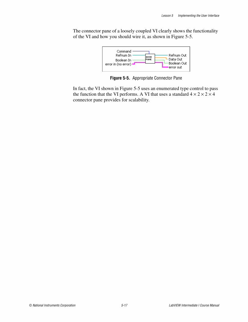
Lesson 5 Implementing the User Interface
© National Instruments Corporation 5-17 LabVIEW Intermediate I Course Manual
The connector pane of a loosely coupled VI clearly shows the functionality of the VI and how you should wire it, as shown in Figure 5-5.
Figure 5-5. Appropriate Connector Pane
In fact, the VI shown in Figure 5-5 uses an enumerated type control to pass the function that the VI performs. A VI that uses a standard 4 × 2 × 2 × 4 connector pane provides for scalability.
Lesson 5 Implementing the User Interface
LabVIEW Intermediate I Course Manual 5-18 ni.com
Exercise 5-3 Implement an Appropriate Connector Pane
GoalImplement an appropriate connector pane for the VI.
ScenarioBuild every VI with the 4 × 2 × 2 × 4 connector pane. This connector pane pattern provides for scalability, maintainability, and readability. The 4 × 2 × 2 × 4 connector pane is very easy to wire on a block diagram.
DesignModify the TLC Main VI by following the connector pane guidelines in this lesson to create a 4 × 2 × 2 × 4 connector pane, as shown at left. Connect the error in and error out clusters on the front panel to the connector pane.
Implementation1. Open the front panel of TLC Main VI.
2. Right-click the VI icon in the upper right corner of the front panel and select Show Connector from the shortcut menu to display the connector pane for the VI.
3. Right-click the connector pane and select Patterns from the shortcut menu. Verify that the connector pane uses the 4 × 2 × 2 × 4 pattern.
4. Use the Wiring tool to connect the error in and error out clusters on the front panel to the connector pane following the guidelines described in this lesson.
5. Right-click the connector pane and select Show Icon from the shortcut menu to display the icon for the VI.
6. Save and close the VI.
End of Exercise 5-3

Lesson 5 Implementing the User Interface
© National Instruments Corporation 5-19 LabVIEW Intermediate I Course Manual
Summary• Implement data structures using scalar data, arrays, or clusters.
• Create icons that represent the functionality of the VI.
• Select an appropriate and consistent connector pane pattern, such as the 4 × 2 × 2 × 4 connector pane pattern.

Lesson 5 Implementing the User Interface
LabVIEW Intermediate I Course Manual 5-20 ni.com
Notes

© National Instruments Corporation 6-1 LabVIEW Intermediate I Course Manual
6Implementing Code
This lesson focuses on creating the algorithms and VIs for your application. You learn techniques to make modular applications and create VIs that are readable and easy to maintain.
Topics
A. Configuration ManagementB. Implementing a Design Pattern
C. Implementing Code
D. Develop Scalable and Maintainable Modules
E. Implement an Error Handling Strategy

Lesson 6 Implementing Code
LabVIEW Intermediate I Course Manual 6-2 ni.com
A. Configuration ManagementConfiguration management is the process of controlling changes and ensuring they are reviewed before they are made. A central focus of the development models described in Lesson 1, Successful Development Practices, is to convert software development from a chaotic, unplanned activity to a controlled process. These models improve software development by establishing specific, measurable goals at each stage of development.
Regardless of how well development proceeds, changes that occur later in the process need to be implemented. For example, customers often introduce new requirements in the design stage, or performance problems discovered during development prompt a reevaluation of the design. You also may need to rewrite a section of code to correct a problem found in testing. Changes can affect any component of the project from the requirements and specification to the design, code, and tests. If these changes are not made carefully, you can introduce new problems that can delay development or degrade quality.
Source Control After you set the project quality requirements, develop a process to deal with changes. This process is important for projects with multiple developers. As developers work on VIs, they need a method to collect and share their work. A simple method to deal with this is to establish a central source repository. If all the development computers are on the network, you can create a shared location that serves as a central source for development. When developers need to modify files, they can retrieve the files from this location. When developers complete their changes, they can return the files to this location.
Common files and areas of overlap introduce the potential for accidental loss of work. If two developers decide to work on the same VI at the same time, only one developer can work on the master copy. The other developer must compare the VIs to determine the differences and incorporate the changes into a new version. Avoid this situation by ensuring good communication among the developers. If each developer notifies the others when he needs to work on a specific VI, the others know not to work on that VI.
Source control is a good solution to the problem of sharing VIs and controlling access to avoid accidental loss of data. Source control makes it easy to set up shared software projects and to retrieve the latest files from a server. After you create a source control project, you can check out a file for development. Checking out a file marks it with your name so other developers know you are working on the file. If you want to modify a file, you can check out the file from source control, make changes, test the
Lesson 6 Implementing Code
© National Instruments Corporation 6-3 LabVIEW Intermediate I Course Manual
changes, and check the file back into source control. After you check in the file, the latest version is available to the development team. Another developer can check out the file to make further modifications.
Note Source control is available only with the Professional Development System.
You must select, install, and configure a source control provider in order to use source control in a software project. In addition to maintaining source code, a source control provider can manage other aspects of a software project. For example, you can use a source control provider to track changes made to feature specifications and other documents. You can control access to these documents and share them as needed. You also can access older versions of the files in source control.
Refer to the KnowledgeBase for the most current list of third-party source control providers that work with LabVIEW.
Source management of all software project-related files is extremely important for developing quality software. Source management is a requirement for certification under existing quality standards, such as ISO 9000.
Retrieving Old Versions of FilesSometimes you might need to retrieve an old version of a file. For example, you might change a file, check it in, and then realize you need to undo the change. You also might want to send a previous version of the software to a customer while you continue development. If the customer reports a problem, you can access a copy of the previous version of the software.
One way to access an old version of a file or project is to keep backup copies. However, unless you back up the file after every change, you do not have access to every version.
Source control provides a way to check in new versions of a file and access previous versions. Depending on how you configure the source control provider, the tools can store multiple versions of a file.
Tracking Changes If you are managing a software project, it is important to monitor changes and track progress toward specific milestone objectives. You can use this information to determine problem areas of a project by identifying which components required many changes.
Lesson 6 Implementing Code
LabVIEW Intermediate I Course Manual 6-4 ni.com
Source control providers maintain a log of all changes made to files and projects. When checking in a file, the provider prompts the developer to write a summary of the changes made. The provider adds this summary information to the log for that file.
You can view the history information for a file or for the system and generate reports that contain the summary information.
In addition, if you back up files at specific checkpoints, you can compare the latest version of a file with another version to verify changes.
Change Control Large software projects can require a formal process for evaluation and approval each time a developer asks to make changes. A formal process can be too restrictive, so be selective when selecting the control mechanisms you introduce into the system.
Deal cautiously with changes to specific components, such as documents related to user requirements, because they generally are worked out through several iterations with the customer. In this case, the word “customer” is used in a general sense. You can be the customer, other departments in a company can be the customer, or you can develop the software under contract for a third party. When you are the customer, adjusting requirements as you move through the specification and even the design stage is much easier. If you are developing for someone else, changing requirements is more difficult.
Source control gives you a degree of control when making changes. You can track all changes, and you can configure a source control provider to maintain previous versions so you can undo changes if necessary. Some source control providers give you more options for controlling software change. For example, with Microsoft Visual SourceSafe, IBM Rational ClearCase, or Perforce, you can control access to files so some users have access to specific files but others do not. You also can specify that anyone can retrieve files but only certain users can make modifications.
With this kind of access control, consider limiting change privileges for requirement documents to specific team members. You also can control access so a user has privileges to modify a file only with the approval of the change request.
The amount of control you apply varies throughout the development process. In the early stages of the project, before formal evaluation of the requirements, you do not need to strictly restrict change access to files nor do you need to follow formal change request processes. After the requirements are approved, however, you can institute stronger controls.
Lesson 6 Implementing Code
© National Instruments Corporation 6-5 LabVIEW Intermediate I Course Manual
Apply the same concept of varying the level of control to specifications, test plans, and code before and after completing a project phase.
Selecting a Source Control ProviderLabVIEW supports several third-party source control providers. Available source control operations in LabVIEW are the same regardless of which third-party provider you select. Specific support or functionality for each operation varies by provider.
In some cases, you might decide to use a specific source control provider because your company has standardized on that application. If not, you must decide which provider you want to use for managing your files. Consult the source control administrator at your company to find out if you should use a specific provider.
After you select and install a source control provider, you must configure LabVIEW to work with that provider. You can configure LabVIEW to work with only one source control provider at a time.
LabVIEW includes two source control integration interface types. On Windows, LabVIEW integrates with any source control provider that supports the Microsoft Source Code Control Interface. On non-Windows platforms, LabVIEW integrates with Perforce using a command line interface. National Instruments has tested LabVIEW with the following third-party providers:
• Perforce
• Microsoft Visual SourceSafe
• MKS Source Integrity
• IBM Rational ClearCase
• Serena Version Manager (PVCS)
Refer to the KnowledgeBase for the most current list of third-party source control providers that work with LabVIEW.
Source Control Operations in LabVIEWAfter you configure LabVIEW to work with a third-party source control provider, you can perform source control operations on any file in a LabVIEW project or on individual VIs. Access the following operations by selecting Tools»Source Control and selecting among the available options. Within a LabVIEW project, you also can use the Source Control toolbar buttons or right-click a file in the Project Explorer window and select the option from the shortcut menu.
Lesson 6 Implementing Code
LabVIEW Intermediate I Course Manual 6-6 ni.com
If you use source control with VIs outside of a LabVIEW project, you cannot perform source control operations on project-specific items, such as project libraries (.lvlib) or projects (.lvproj).
Note When you attempt to perform source control operations on a VI in an LLB, LabVIEW performs the operations on the LLB that contains the VI, not on the VI itself. You cannot perform a source control operation on only one VI in an LLB.
• Get Latest Version—Copies the latest version of the selected file from source control to the local directory to synchronize the two versions. The latest version of the file in source control overwrites the version in the local directory.
• Check In—Checks the selected file into source control. A new version with the changes you made replaces the previous version in source control.
• Check Out—Checks out the selected file from source control. If you try to edit a file in source control that you did not check out, LabVIEW prompts you to check out the file if you configured source control to enable the prompt.
• Undo Check Out—Cancels a previous check-out operation and restores the contents of the selected file to the previous version. Any changes you made to the file are lost.
• Add to Source Control—Adds the selected file to source control. LabVIEW prompts you to add any dependent files, such as subVIs, to source control if you configured source control to enable the prompt.
• Remove from Source Control—Removes the selected file from source control.
Caution Be careful when you remove files from source control. Some source control providers delete the local directory copy of the file, all previous versions of the file that the provider maintains, and the history log for the file.
• Show History—Displays the source control history of the selected file. The history contains a record of changes to the file after it was added to source control. The history provides information about the previous versions of the file, such as file check-in dates and user actions.
• Show Differences—Displays the differences between the local copy of the selected file and the version in source control. For text files, LabVIEW uses the default comparison tool of the source control provider. If you select a VI to compare and have configured LabVIEW to work with Microsoft Visual SourceSafe or the Perforce command line interface, LabVIEW uses the VI Compare tool.
Lesson 6 Implementing Code
© National Instruments Corporation 6-7 LabVIEW Intermediate I Course Manual
• Properties—Displays the source control properties for the selected file, including its check-out status and modification dates.
• Refresh Status—Updates the source control status of the files in the LabVIEW project, or of the VI if you are working outside a LabVIEW project.
• Run Source Control Client—Launches the file management client of the source control provider.
B. Implementing a Design PatternLesson 3, Designing the User Interface, described how to select an appropriate design pattern to form the underlying scalable architecture for a VI. When you implement a chosen design pattern to create a scalable architecture, consider how you want to initialize the VI and pass data in the VI.
Initializing a Design PatternYou must initialize any VI you create that is based on a design pattern. Design patterns such as the state machine or producer/consumer require some form of initialization to ensure that the VI is in a known state when execution begins. There are several techniques you can use to initialize a design pattern.
Initializing with a Single Frame Sequence StructureThe most common technique to initialize a design pattern uses a single frame Sequence structure that executes before the design pattern executes. For example, the producer/consumer design pattern shown in Figure 6-1 uses a single frame Sequence structure to initialize the queue and the front panel controls. Notice that the Sequence structure uses a local variable to initialize front panel controls. This is an acceptable use of local variables.
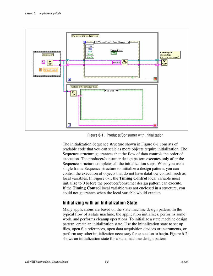
Lesson 6 Implementing Code
LabVIEW Intermediate I Course Manual 6-8 ni.com
Figure 6-1. Producer/Consumer with Initialization
The initialization Sequence structure shown in Figure 6-1 consists of readable code that you can scale as more objects require initialization. The Sequence structure guarantees that the flow of data controls the order of execution. The producer/consumer design pattern executes only after the Sequence structure completes all the initialization steps. When you use a single frame Sequence structure to initialize a design pattern, you can control the execution of objects that do not have dataflow control, such as local variables. In Figure 6-1, the Timing Control local variable must initialize to 0 before the producer/consumer design pattern can execute. If the Timing Control local variable was not enclosed in a structure, you could not guarantee when the local variable would execute.
Initializing with an Initialization StateMany applications are based on the state machine design pattern. In the typical flow of a state machine, the application initializes, performs some work, and performs cleanup operations. To initialize a state machine design pattern, create an initialization state. Use the initialization state to set up files, open file references, open data acquisition devices or instruments, or perform any other initialization necessary for execution to begin. Figure 6-2 shows an initialization state for a state machine design pattern.
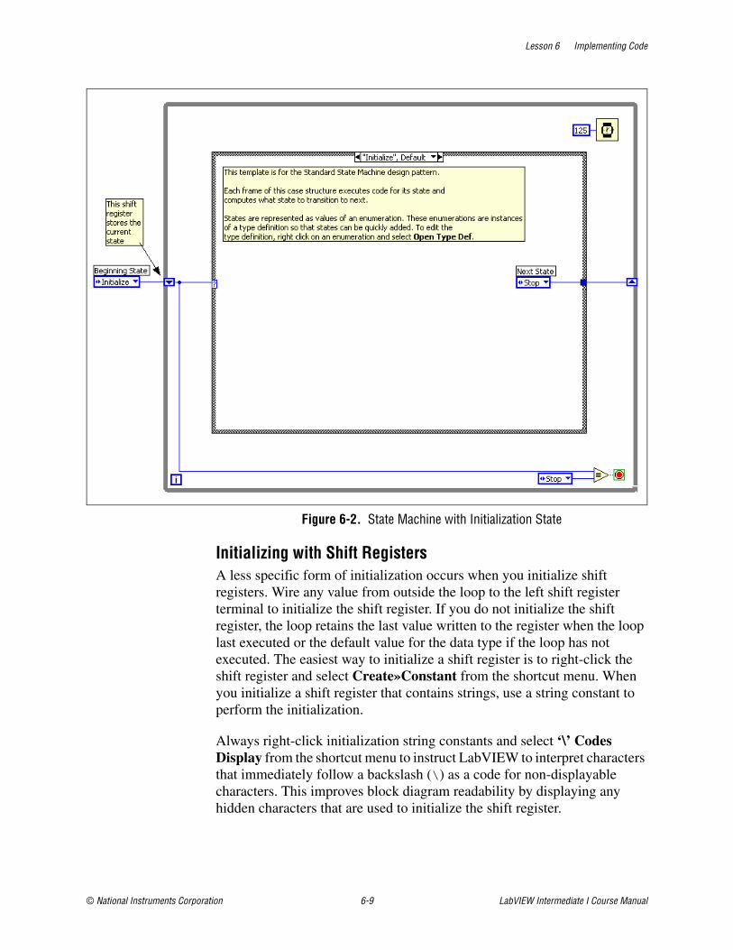
Lesson 6 Implementing Code
© National Instruments Corporation 6-9 LabVIEW Intermediate I Course Manual
Figure 6-2. State Machine with Initialization State
Initializing with Shift RegistersA less specific form of initialization occurs when you initialize shift registers. Wire any value from outside the loop to the left shift register terminal to initialize the shift register. If you do not initialize the shift register, the loop retains the last value written to the register when the loop last executed or the default value for the data type if the loop has not executed. The easiest way to initialize a shift register is to right-click the shift register and select Create»Constant from the shortcut menu. When you initialize a shift register that contains strings, use a string constant to perform the initialization.
Always right-click initialization string constants and select ‘\’ Codes Display from the shortcut menu to instruct LabVIEW to interpret characters that immediately follow a backslash (\) as a code for non-displayable characters. This improves block diagram readability by displaying any hidden characters that are used to initialize the shift register.

Lesson 6 Implementing Code
LabVIEW Intermediate I Course Manual 6-10 ni.com
Data Types for Passing DataWhen you use the producer/consumer (events) design pattern, you often need to pass more than one type of data within a VI. Using a cluster containing a variant and an enumerated type control gives you the flexibility to pass data and commands to the consumer loop. The variant enables you to pass any data type from the producer to the consumer, and the enumerated type control enables the producer to control what function the consumer performs.
Variant DataVariant data do not conform to a specific data type and can contain attributes. LabVIEW represents variant data with the variant data type. The variant data type differs from other data types because it stores the control or indicator name, information about the data type from which you converted, and the data itself, which allows LabVIEW to correctly convert the variant data type to the data type you want. For example, if you convert a string data type to a variant data type, the variant data type stores the text and indicates that the text is a string.
Use the Variant functions to create and manipulate variant data. You can convert any LabVIEW data type to the variant data type to use variant data in other VIs and functions. Several polymorphic functions return the variant data type.
Use the variant data type when it is important to manipulate data independently of data type, such as when you transmit or store data; read and/or write to unknown devices; or perform operations on a heterogeneous set of controls.
Using Variant Data TypesVariant data types allow you to create VIs that have a greater degree of generality. They allow a VI to manipulate data without specifying what kind of data it is when the VI compiles. Using variant data types with the producer/consumer design patterns gives you greater flexibility. Use a cluster with an enumerated type control and variant, shown at left, to perform two functions at once. The variant data type enables you to pass any data type from the producer to the consumer, and the enumerated data type enables the producer to control what function the consumer performs.
Figure 6-3 shows a producer/consumer (events) design pattern that uses a cluster with an enumerated data type and variant data. In this example, when the Configure event generates, the data that should pass to the consumer is converted to variant data and bundled with the enumerated data type to control the function of the consumer. The consumer loop unbundles the cluster and passes the enumerated data type to the Case structure to control

Lesson 6 Implementing Code
© National Instruments Corporation 6-11 LabVIEW Intermediate I Course Manual
the function of the consumer. The variant data then passes into the Case structure, where the variant data is converted to the data type. The advantage to using this data type is any other event cases can pass any type or form of data to the consumer. This provides for scalable and readable code.
Note If you are using the Real-Time platform, replace the variant data type with a string data type.
Figure 6-3. Producer/Consumer (Events) with Cluster of Enumerated Data Type
Job AidUse the following checklist to implement scalable architectures.
❑ Use a single frame Sequence structure to initialize a design pattern.
❑ Make sure that all architectures perform a proper initialization and cleanup.
❑ Implement the control code using a type defined enumerated type control.
Lesson 6 Implementing Code
LabVIEW Intermediate I Course Manual 6-12 ni.com
Exercise 6-1 Implement the Design Pattern
GoalImplement a design pattern as the basis for the application architecture.
ScenarioUsing a design pattern for the architecture makes the application readable, scalable, and maintainable. Implementing the producer/consumer (events) design pattern makes the user interface more responsive. Using a variant data type makes the architecture scalable for future needs.
Design1. Create a type definition for the functions that the application performs.
2. Use the type definition as the data type to pass data from the producer to the consumer.
3. Initialize the design pattern.
4. In the consumer loop of the design pattern, make sure a case exists to process each function in the enumerated data type.
5. Enqueue an element into the producer/consumer with (events) queue when an event is received in the producer.
6. Create a custom run-time menu to perform the Load, Save, and Exit functions.
7. Add a case to the Event structure in the producer loop to respond to menu selections.
8. Create user events that allow the consumer loop to send error data to the producer loop to stop the producer
ImplementationImplement the scalable architecture that you chose in Exercise 4-5.
1. Open the TLC Main VI in the Project Explorer window.
2. Complete the steps below to build a functioning producer/consumer (events) design pattern as shown in Figure 6-4.

Lesson 6 Implementing Code
© National Instruments Corporation 6-13 LabVIEW Intermediate I Course Manual
Figu
re 6
-4.
Thea
tre L
ight
Con
trolle
r Arc
hite
ctur
e
Lesson 6 Implementing Code
LabVIEW Intermediate I Course Manual 6-14 ni.com
3. Create an enumerated type control type definition with the following items for the functions that the application performs:
– Initialize
– Record
– Load
– Save
– Play
– Move Cue Up
– Move Cue Down
– Select Cue
– Delete
– Stop
– Exit
❑ Select File»New to open the New dialog box.
❑ Select Other Files»Custom Control from the Create New tree.
❑ Make sure a checkmark appears in the Add to project checkbox.
❑ Click the OK button.
❑ Place an enumerated type control on the front panel of the Control Editor.
❑ Right-click the enum and select Edit Items from the shortcut menu to create items for the functions in the previous bulleted list.
❑ Change the label of the enum to Command.
❑ Select Type Def. from the Type Def. Status pull-down menu.
❑ Save the type definition as tlc_Functions.ctl in the C:\Exercises\LabVIEW Intermediate I\Course Project\Controls directory.
❑ Close the Control Editor.
❑ Move the tlc_Functions.ctl control into the Controls folder in the Project Explorer window.
4. Create a scalable data type to pass data from the producer loop to the consumer loop. This data type is a cluster that includes the tlc_Functions.ctl control and a variant.

Lesson 6 Implementing Code
© National Instruments Corporation 6-15 LabVIEW Intermediate I Course Manual
❑ Select File»New to open the New dialog box.
❑ Select Other Files»Custom Control from the Create New tree.
❑ Verify Add to project is selected.
❑ Click the OK button to open the Control Editor.
❑ Place a cluster on the front panel of the Control Editor.
❑ Change the label of the cluster to tlc_Consumer Control.ctl, to correspond to the name of the file. Using the filename of the control as a label helps you keep track of the controls on the block diagram.
❑ Drag the tlc_Functions.ctl type definition from the Project Explorer window to the cluster.
❑ Change the label of tlc_Functions.ctl to Command.
❑ Place a variant control in the cluster.
❑ Change the label of the variant to Data.
Figure 6-5 shows the resulting cluster.
Figure 6-5. Variant and Type Definition Enumerated Control Cluster
❑ Select Type Def. from the Type Def. Status pull-down menu.
❑ Save the type definition as tlc_Consumer Control.ctl in the C:\Exercises\LabVIEW Intermediate I\Course Project\Controls directory.
❑ Close the Control Editor.
Lesson 6 Implementing Code
LabVIEW Intermediate I Course Manual 6-16 ni.com
❑ Move the tlc_Consumer Control.ctl control to the Controls folder in the Project Explorer window.
5. Drag tlc_Consumer Control.ctl to the block diagram to place it as a constant. Position the constant outside the producer and consumer loops.
6. Initialize the design pattern.
❑ Delete the empty string constant that is wired to the Obtain Queue function.
❑ Set the enumerated type control of the constant to Initialize and wire the constant to the element data type input of the Obtain Queue function.
❑ Place the Enqueue Element function on the block diagram. Wire the cluster constant to the Enqueue Element function to initialize the design pattern.
7. Create a custom control for the queue reference that the Obtain Queue generates. You use this reference to enqueue items in the queue within subVIs.
❑ Right-click the queue out terminal of the Obtain Queue function and select Create»Control from the shortcut menu to create the reference.
❑ Double-click the queue out reference to locate the object on the front panel.
❑ Right-click the control and select Advanced»Customize from the shortcut menu to open the Control Editor.
❑ Select Type Def. from the Type Def. Status pull-down menu.
❑ Label the control tlc_Consumer Queue Reference.ctl.
❑ Save the control as tlc_Consumer Queue Reference.ctl in the C:\Exercises\LabVIEW Intermediate I\Course Project\Controls directory.
❑ Close the Control Editor. When prompted, replace the original control with the custom control.
❑ Move the tlc_Consumer Queue Reference.ctl control to the Controls folder in the Project Explorer window.
Lesson 6 Implementing Code
© National Instruments Corporation 6-17 LabVIEW Intermediate I Course Manual
❑ Delete the control from the TLC Main VI. You use this custom control reference when you build the display module.
8. In the consumer loop of the design pattern, make sure a case exists to process each function in the enumerated data type.
❑ Place the Unbundle by Name function outside the Case structure in the consumer loop.
❑ Wire the element output of the Dequeue Element function to the input of the Unbundle by Name function.
❑ Delete the error cluster wire connected to the case selector terminal. In a later exercise you implement a functional global variable to handle errors in the application.
❑ Wire the Command element of the Unbundle by Name function to the case selector terminal of the Case structure.
❑ Right-click the border of the Case structure and select Add Case For Every Value from the shortcut menu to populate the Case structure with the items in the enumerated type control.
❑ Wire a False constant to the loop condition terminal of the While Loop in each case of the Case structure. Change the constant in the Exit case to True to enable the Exit case to stop the consumer loop.
❑ Wire the queue out refnum and error cluster through each of the cases.
9. Create an event case in the producer loop to respond to the Value Change event for the Play button.
❑ Right-click the Event structure and select Add Event Case from the shortcut menu to open the Edit Events dialog box.
❑ Select the Play button from the Event Sources list and select Value Change from the Events list.
❑ Click the OK button.
10. Modify the Play event case to send a message to the consumer loop to execute Play, as shown in Figure 6-6.
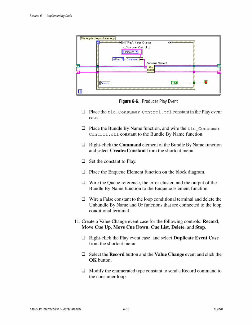
Lesson 6 Implementing Code
LabVIEW Intermediate I Course Manual 6-18 ni.com
Figure 6-6. Producer Play Event
❑ Place the tlc_Consumer Control.ctl constant in the Play event case.
❑ Place the Bundle By Name function, and wire the tlc_Consumer Control.ctl constant to the Bundle By Name function.
❑ Right-click the Command element of the Bundle By Name function and select Create»Constant from the shortcut menu.
❑ Set the constant to Play.
❑ Place the Enqueue Element function on the block diagram.
❑ Wire the Queue reference, the error cluster, and the output of the Bundle By Name function to the Enqueue Element function.
❑ Wire a False constant to the loop conditional terminal and delete the Unbundle By Name and Or functions that are connected to the loop conditional terminal.
11. Create a Value Change event case for the following controls: Record, Move Cue Up, Move Cue Down, Cue List, Delete, and Stop.
❑ Right-click the Play event case, and select Duplicate Event Case from the shortcut menu.
❑ Select the Record button and the Value Change event and click the OK button.
❑ Modify the enumerated type constant to send a Record command to the consumer loop.
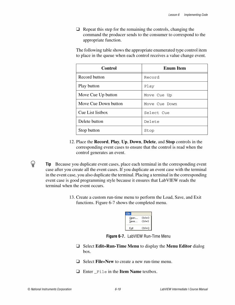
Lesson 6 Implementing Code
© National Instruments Corporation 6-19 LabVIEW Intermediate I Course Manual
❑ Repeat this step for the remaining the controls, changing the command the producer sends to the consumer to correspond to the appropriate function.
The following table shows the appropriate enumerated type control item to place in the queue when each control receives a value change event.
12. Place the Record, Play, Up, Down, Delete, and Stop controls in the corresponding event cases to ensure that the control is read when the control generates an event.
Tip Because you duplicate event cases, place each terminal in the corresponding event case after you create all the event cases. If you duplicate an event case with the terminal in the event case, you also duplicate the terminal. Placing a terminal in the corresponding event case is good programming style because it ensures that LabVIEW reads the terminal when the event occurs.
13. Create a custom run-time menu to perform the Load, Save, and Exit functions. Figure 6-7 shows the completed menu.
Figure 6-7. LabVIEW Run-Time Menu
❑ Select Edit»Run-Time Menu to display the Menu Editor dialog box.
❑ Select File»New to create a new run-time menu.
❑ Enter _File in the Item Name textbox.
Control Enum Item
Record button Record
Play button Play
Move Cue Up button Move Cue Up
Move Cue Down button Move Cue Down
Cue List listbox Select Cue
Delete button Delete
Stop button Stop
Lesson 6 Implementing Code
LabVIEW Intermediate I Course Manual 6-20 ni.com
Tip Enter an underscore (_) before the letter you want to associate with the <Alt> key for that menu. When you associate a letter with the <Alt> key, the user can press the <Alt> key and the associated key to access the menu.
❑ Click the blue + button on the Menu Editor toolbar to add a new item under the File item.
❑ Click the right arrow button on the toolbar to make the new item a subitem of the File menu.
❑ Enter _Open... in the Item Name textbox to create a menu item for Open.
❑ Modify the Item Tag to Open.
❑ Assign the shortcut <Ctrl+O> to this menu item.
Note The Item Tag is passed to LabVIEW so that you can create decision making code to respond to the selected menu item.
❑ Click the blue + button on the Menu Editor toolbar to add a new item under the File item.
❑ Click the right arrow button on the toolbar to make the new item a subitem of the File menu.
❑ Enter _Save... in the Item Name textbox to create a menu item for Save.
❑ Modify the Item Tag to Save.
❑ Assign the shortcut <Ctrl+S> to this menu item.
❑ Click the blue + button on the Menu Editor toolbar to add a new item under the File»Save item.
❑ Create a menu Separator by selecting Separator from the Item Type drop-down menu.
❑ Click the blue + button on the Menu Editor toolbar to add a new item under the File item.
❑ Click the right arrow button on the toolbar to make the new item a subitem of the File menu.
❑ Enter E_xit in the Item Name textbox to create a menu item for Exit.

Lesson 6 Implementing Code
© National Instruments Corporation 6-21 LabVIEW Intermediate I Course Manual
❑ Modify the Item Tag to Exit.
❑ Assign the shortcut <Ctrl+Q> to this menu item.
❑ Select File in the Preview section to preview the menu and verify that it matches Figure 6-7.
❑ Save the run-time menu as tlc_Menu.rtm in the C:\Exercises\LabVIEW Intermediate I\Course Project\Menu directory.
❑ Close the Menu Editor. When prompted, click the Yes button to change the run-time menu to the custom menu.
14. Add a case to the Event structure in the producer loop to respond to menu selections.
❑ Right-click the Event structure border and select Add Event Case from the shortcut menu to open the Edit Events dialog box.
❑ Select <This VI> from the Event Sources list and Menu Selection (User) from the Events list to create the Menu Selection (User) event case. Click the OK button.
❑ Place a Case structure in the Menu Selection (User) event case. Wire the ItemTag event data node to the case selector terminal.
❑ Create four cases for the Case structure in the Menu Selection (User) event case to process the ItemTag strings—Open, Save, Exit, and Default. Make sure the spelling for the case selector matches the spelling you used for the Item Tag in the Menu Editor. Delete any unused cases.
❑ Modify the Exit case to stop the VI when the user selects File»Exit, as shown in Figure 6-8.
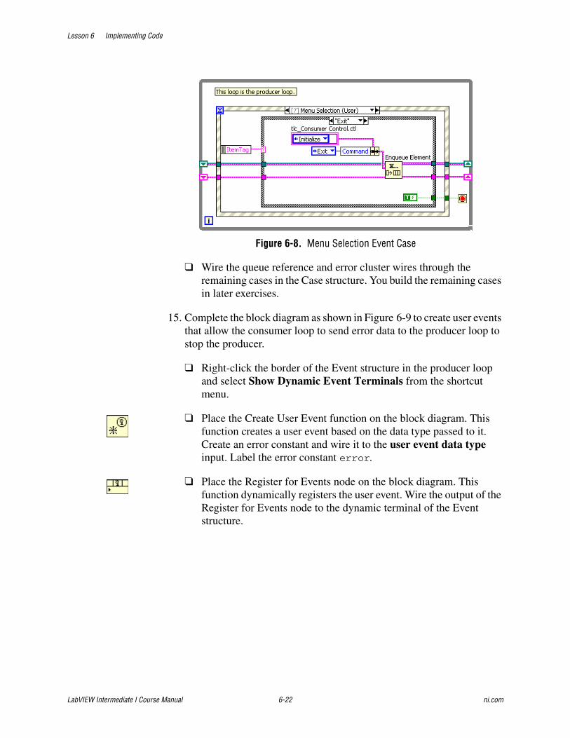
Lesson 6 Implementing Code
LabVIEW Intermediate I Course Manual 6-22 ni.com
Figure 6-8. Menu Selection Event Case
❑ Wire the queue reference and error cluster wires through the remaining cases in the Case structure. You build the remaining cases in later exercises.
15. Complete the block diagram as shown in Figure 6-9 to create user events that allow the consumer loop to send error data to the producer loop to stop the producer.
❑ Right-click the border of the Event structure in the producer loop and select Show Dynamic Event Terminals from the shortcut menu.
❑ Place the Create User Event function on the block diagram. This function creates a user event based on the data type passed to it. Create an error constant and wire it to the user event data type input. Label the error constant error.
❑ Place the Register for Events node on the block diagram. This function dynamically registers the user event. Wire the output of the Register for Events node to the dynamic terminal of the Event structure.
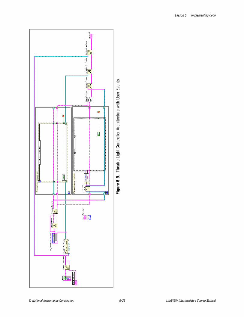
Lesson 6 Implementing Code
© National Instruments Corporation 6-23 LabVIEW Intermediate I Course Manual
Figu
re 6
-9.
Thea
tre L
ight
Con
trolle
r Arc
hite
ctur
e w
ith U
ser E
vent
s
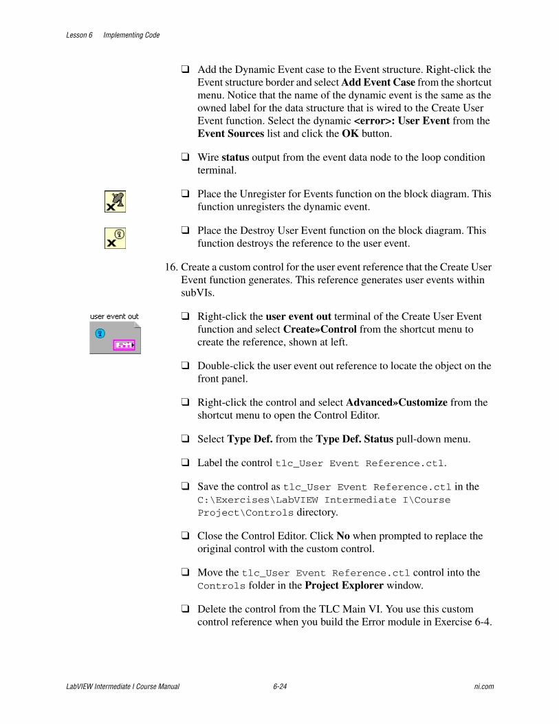
Lesson 6 Implementing Code
LabVIEW Intermediate I Course Manual 6-24 ni.com
❑ Add the Dynamic Event case to the Event structure. Right-click the Event structure border and select Add Event Case from the shortcut menu. Notice that the name of the dynamic event is the same as the owned label for the data structure that is wired to the Create User Event function. Select the dynamic <error>: User Event from the Event Sources list and click the OK button.
❑ Wire status output from the event data node to the loop condition terminal.
❑ Place the Unregister for Events function on the block diagram. This function unregisters the dynamic event.
❑ Place the Destroy User Event function on the block diagram. This function destroys the reference to the user event.
16. Create a custom control for the user event reference that the Create User Event function generates. This reference generates user events within subVIs.
❑ Right-click the user event out terminal of the Create User Event function and select Create»Control from the shortcut menu to create the reference, shown at left.
❑ Double-click the user event out reference to locate the object on the front panel.
❑ Right-click the control and select Advanced»Customize from the shortcut menu to open the Control Editor.
❑ Select Type Def. from the Type Def. Status pull-down menu.
❑ Label the control tlc_User Event Reference.ctl.
❑ Save the control as tlc_User Event Reference.ctl in the C:\Exercises\LabVIEW Intermediate I\Course Project\Controls directory.
❑ Close the Control Editor. Click No when prompted to replace the original control with the custom control.
❑ Move the tlc_User Event Reference.ctl control into the Controls folder in the Project Explorer window.
❑ Delete the control from the TLC Main VI. You use this custom control reference when you build the Error module in Exercise 6-4.
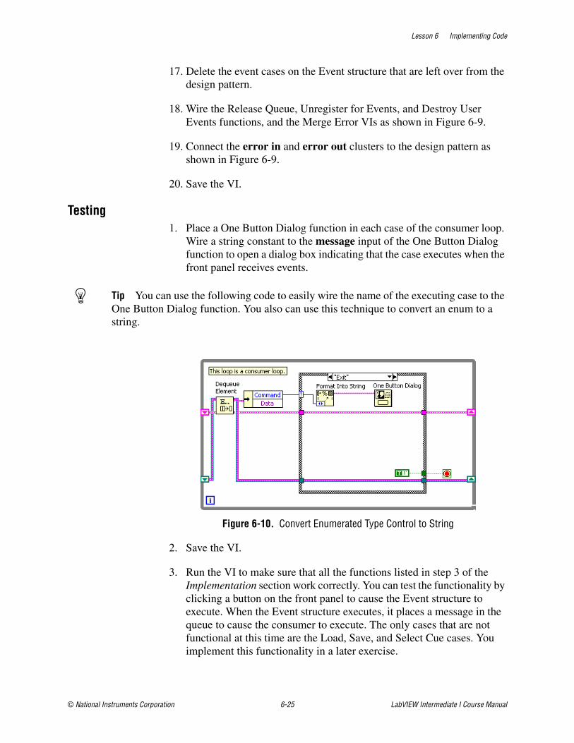
Lesson 6 Implementing Code
© National Instruments Corporation 6-25 LabVIEW Intermediate I Course Manual
17. Delete the event cases on the Event structure that are left over from the design pattern.
18. Wire the Release Queue, Unregister for Events, and Destroy User Events functions, and the Merge Error VIs as shown in Figure 6-9.
19. Connect the error in and error out clusters to the design pattern as shown in Figure 6-9.
20. Save the VI.
Testing1. Place a One Button Dialog function in each case of the consumer loop.
Wire a string constant to the message input of the One Button Dialog function to open a dialog box indicating that the case executes when the front panel receives events.
Tip You can use the following code to easily wire the name of the executing case to the One Button Dialog function. You also can use this technique to convert an enum to a string.
Figure 6-10. Convert Enumerated Type Control to String
2. Save the VI.
3. Run the VI to make sure that all the functions listed in step 3 of the Implementation section work correctly. You can test the functionality by clicking a button on the front panel to cause the Event structure to execute. When the Event structure executes, it places a message in the queue to cause the consumer to execute. The only cases that are not functional at this time are the Load, Save, and Select Cue cases. You implement this functionality in a later exercise.

Lesson 6 Implementing Code
LabVIEW Intermediate I Course Manual 6-26 ni.com
4. Verify that you can exit the application from the run-time menu.
5. Close the TLC Main VI.
End of Exercise 6-1
Lesson 6 Implementing Code
© National Instruments Corporation 6-27 LabVIEW Intermediate I Course Manual
C. Implementing CodeDeveloping code and interfaces is the process of implementing the actual VI. Good software design techniques ensure that you create VIs that are scalable, readable, and maintainable. When you implement code, you also must provide a timing mechanism and document the VI.
Practice LabVIEW Style GuidelinesPracticing good LabVIEW style is one of the best ways to prevent bugs or errors in the code. Keeping the block diagram clean and easy to read can minimize the amount of debugging an application requires. Using good style might increase the time required to implement code, but you actually save time because using good style can reduce the time you spend debugging and testing a VI.
Maintain Appropriate Size of Block DiagramThe size of the block diagram window can affect how readable LabVIEW code is to others. Make the block diagram window no larger than the screen size. Code that is larger than the window is hard to read because it forces users to scroll through the window. If the code is too large to fit on one screen, make sure the user has to scroll only in one direction to view the rest of the code. If the block diagram requires scrolling, consider using subVIs.
Use Proper Wiring TechniquesUse the Align Objects and Distribute Objects pull-down menus on the toolbar to arrange objects symmetrically on the block diagram. When objects are aligned and distributed evenly, you can use straight wires to wire the objects together. Using straight wires makes the block diagram easier to read.
The following good wiring tips also help keep the block diagram clean:
• Avoid placing any wires under block diagram objects because LabVIEW can hide some segments of the resulting wire. Draw wires so that you can clearly see if a wire correctly connects to a terminal. Delete any extraneous wires. Do not wire through structures if the data in the wire is not used in the structure.
• Add as few bends in the wires as possible and keep the wires short. Avoid creating wires with long complicated paths because long wires are confusing to follow.
• Avoid using local variables when you can use a wire to transfer data. Every local variable that reads the data makes a copy of the data. Use global and local variables as sparingly as possible.
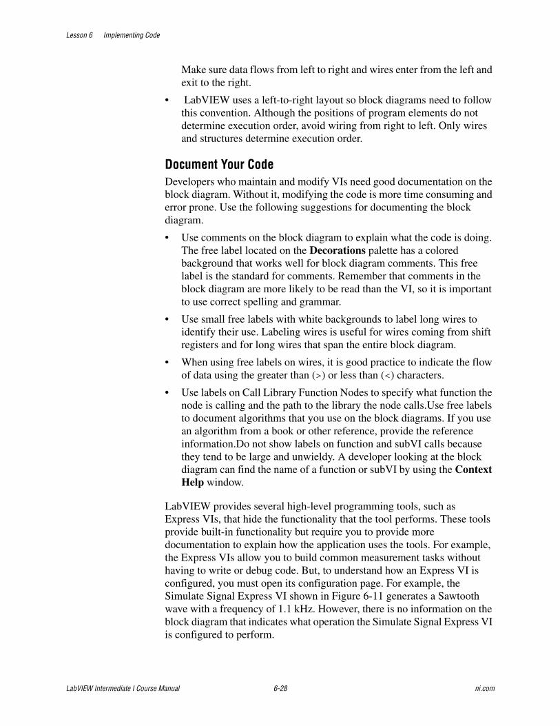
Lesson 6 Implementing Code
LabVIEW Intermediate I Course Manual 6-28 ni.com
Make sure data flows from left to right and wires enter from the left and exit to the right.
• LabVIEW uses a left-to-right layout so block diagrams need to follow this convention. Although the positions of program elements do not determine execution order, avoid wiring from right to left. Only wires and structures determine execution order.
Document Your CodeDevelopers who maintain and modify VIs need good documentation on the block diagram. Without it, modifying the code is more time consuming and error prone. Use the following suggestions for documenting the block diagram.
• Use comments on the block diagram to explain what the code is doing. The free label located on the Decorations palette has a colored background that works well for block diagram comments. This free label is the standard for comments. Remember that comments in the block diagram are more likely to be read than the VI, so it is important to use correct spelling and grammar.
• Use small free labels with white backgrounds to label long wires to identify their use. Labeling wires is useful for wires coming from shift registers and for long wires that span the entire block diagram.
• When using free labels on wires, it is good practice to indicate the flow of data using the greater than (>) or less than (<) characters.
• Use labels on Call Library Function Nodes to specify what function the node is calling and the path to the library the node calls.Use free labels to document algorithms that you use on the block diagrams. If you use an algorithm from a book or other reference, provide the reference information.Do not show labels on function and subVI calls because they tend to be large and unwieldy. A developer looking at the block diagram can find the name of a function or subVI by using the Context Help window.
LabVIEW provides several high-level programming tools, such as Express VIs, that hide the functionality that the tool performs. These tools provide built-in functionality but require you to provide more documentation to explain how the application uses the tools. For example, the Express VIs allow you to build common measurement tasks without having to write or debug code. But, to understand how an Express VI is configured, you must open its configuration page. For example, the Simulate Signal Express VI shown in Figure 6-11 generates a Sawtooth wave with a frequency of 1.1 kHz. However, there is no information on the block diagram that indicates what operation the Simulate Signal Express VI is configured to perform.

Lesson 6 Implementing Code
© National Instruments Corporation 6-29 LabVIEW Intermediate I Course Manual
Figure 6-11. Configured Simulate Signal Express VI
You can dramatically improve the readability of the Simulate Signal Express VI by documenting its configuration. If you idle the mouse over an Express VI when the Context Help window is open, the current configuration displays in the Context Help window, as shown in Figure 6-12.
Figure 6-12. Context Help for Simulate Signal Express VI
You can use the information that is located in the Context Help window to create a free label comment on the block diagram that documents the configuration of Express VIs, as shown in Figure 6-13.

Lesson 6 Implementing Code
LabVIEW Intermediate I Course Manual 6-30 ni.com
Figure 6-13. Fully Documented Express VI
Data binding is another tool that hides its functionality in a VI. The VIs in Figure 6-14 and Figure 6-15 communicate with one another using shared variables, but there is no indication of that functionality on either block diagram.
Figure 6-14. Writes Data to a Shared Variable
Figure 6-15. Reads Data from a Shared Variable Server
The VI in Figure 6-15 reads data from the VI in Figure 6-14. There is nothing on the block diagram to indicate that this VI reads data through a shared variable. Looking at the VI in Figure 6-15, you would not expect the waveform graph to update. But, when you run the VI, it receives data. You should always clearly document VIs that receive data through data binding.
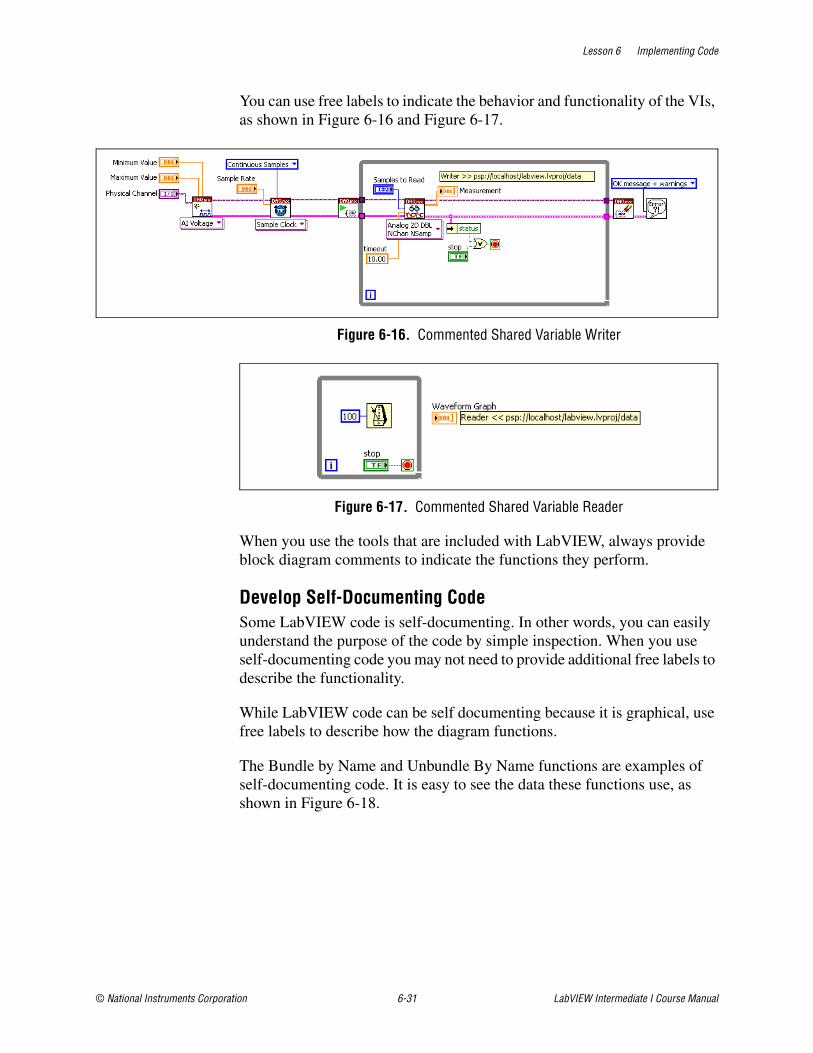
Lesson 6 Implementing Code
© National Instruments Corporation 6-31 LabVIEW Intermediate I Course Manual
You can use free labels to indicate the behavior and functionality of the VIs, as shown in Figure 6-16 and Figure 6-17.
Figure 6-16. Commented Shared Variable Writer
Figure 6-17. Commented Shared Variable Reader
When you use the tools that are included with LabVIEW, always provide block diagram comments to indicate the functions they perform.
Develop Self-Documenting CodeSome LabVIEW code is self-documenting. In other words, you can easily understand the purpose of the code by simple inspection. When you use self-documenting code you may not need to provide additional free labels to describe the functionality.
While LabVIEW code can be self documenting because it is graphical, use free labels to describe how the diagram functions.
The Bundle by Name and Unbundle By Name functions are examples of self-documenting code. It is easy to see the data these functions use, as shown in Figure 6-18.
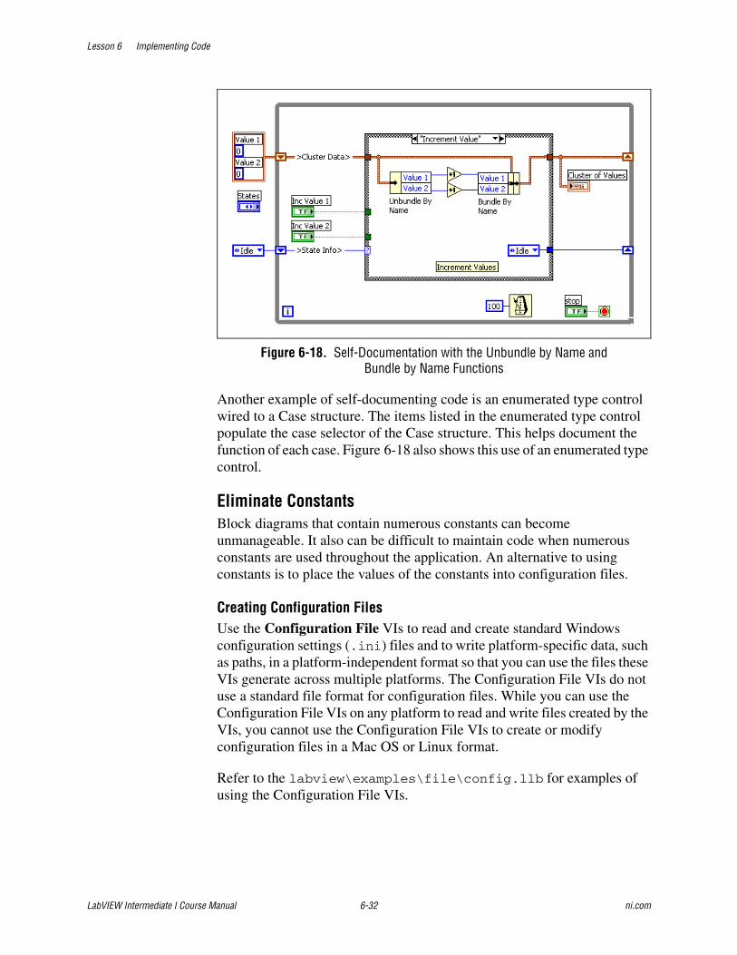
Lesson 6 Implementing Code
LabVIEW Intermediate I Course Manual 6-32 ni.com
Figure 6-18. Self-Documentation with the Unbundle by Name and Bundle by Name Functions
Another example of self-documenting code is an enumerated type control wired to a Case structure. The items listed in the enumerated type control populate the case selector of the Case structure. This helps document the function of each case. Figure 6-18 also shows this use of an enumerated type control.
Eliminate ConstantsBlock diagrams that contain numerous constants can become unmanageable. It also can be difficult to maintain code when numerous constants are used throughout the application. An alternative to using constants is to place the values of the constants into configuration files.
Creating Configuration FilesUse the Configuration File VIs to read and create standard Windows configuration settings (.ini) files and to write platform-specific data, such as paths, in a platform-independent format so that you can use the files these VIs generate across multiple platforms. The Configuration File VIs do not use a standard file format for configuration files. While you can use the Configuration File VIs on any platform to read and write files created by the VIs, you cannot use the Configuration File VIs to create or modify configuration files in a Mac OS or Linux format.
Refer to the labview\examples\file\config.llb for examples of using the Configuration File VIs.
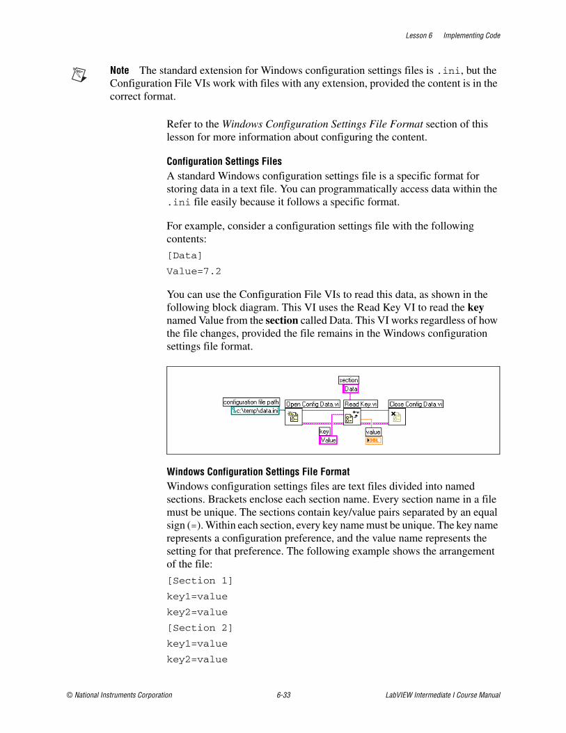
Lesson 6 Implementing Code
© National Instruments Corporation 6-33 LabVIEW Intermediate I Course Manual
Note The standard extension for Windows configuration settings files is .ini, but the Configuration File VIs work with files with any extension, provided the content is in the correct format.
Refer to the Windows Configuration Settings File Format section of this lesson for more information about configuring the content.
Configuration Settings FilesA standard Windows configuration settings file is a specific format for storing data in a text file. You can programmatically access data within the .ini file easily because it follows a specific format.
For example, consider a configuration settings file with the following contents:
[Data]
Value=7.2
You can use the Configuration File VIs to read this data, as shown in the following block diagram. This VI uses the Read Key VI to read the key named Value from the section called Data. This VI works regardless of how the file changes, provided the file remains in the Windows configuration settings file format.
Windows Configuration Settings File FormatWindows configuration settings files are text files divided into named sections. Brackets enclose each section name. Every section name in a file must be unique. The sections contain key/value pairs separated by an equal sign (=). Within each section, every key name must be unique. The key name represents a configuration preference, and the value name represents the setting for that preference. The following example shows the arrangement of the file:
[Section 1]
key1=value
key2=value
[Section 2]
key1=value
key2=value

Lesson 6 Implementing Code
LabVIEW Intermediate I Course Manual 6-34 ni.com
Use the following data types with Configuration File VIs for the value portion of the key parameter:
• String
• Path
• Boolean
• 64-bit double-precision floating-point numeric
• 32-bit signed integer
• 32-bit unsigned integer
The Configuration File VIs can read and write raw or escaped string data. The VIs read and write raw data byte-for-byte, without converting the data to ASCII. In converted, or escaped, strings LabVIEW stores any non-displayable text characters in the configuration settings file with the equivalent hexadecimal escape codes, such as \0D for a carriage return. In addition, LabVIEW stores backslash characters in the configuration settings file as double backslashes, such as \\ for \. Set the read raw string? or write raw string? inputs of the Configuration File VIs to TRUE for raw data and to FALSE for escaped data.
When VIs write to a configuration file, they place quotation marks around any string or path data that contain a space character. If a string contains quotation marks, LabVIEW stores them as \". If you read and/or write to configuration files using a text editor, you might notice that LabVIEW replaced quotation marks with \".
LabVIEW stores path data in a platform-independent format, the standard Linux format for paths, in .ini files. The VIs interpret the absolute path /c/temp/data.dat stored in a configuration settings file as follows:
• (Windows) c:\temp\data.dat
• (Mac OS) c:temp:data.dat
• (Linux) /c/temp/data.dat
The VIs interpret the relative path temp/data.dat as follows:
• (Windows) temp\data.dat
• (Mac OS) :temp:data.dat
• (Linux) temp/data.dat
Organize the File StructureOrganize the VIs in the file system to reflect the hierarchical nature of the software. Make top-level VIs directly accessible. Place subVIs in subdirectories and group them to reflect any modular components you have
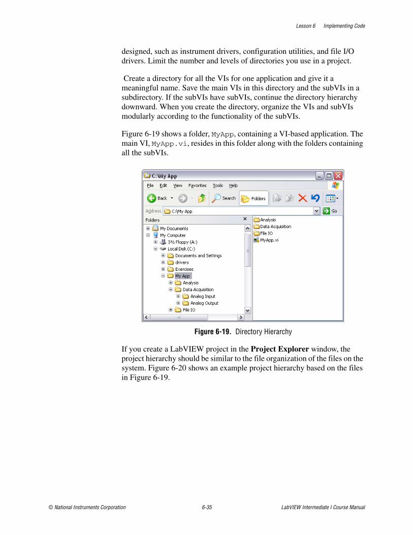
Lesson 6 Implementing Code
© National Instruments Corporation 6-35 LabVIEW Intermediate I Course Manual
designed, such as instrument drivers, configuration utilities, and file I/O drivers. Limit the number and levels of directories you use in a project.
Create a directory for all the VIs for one application and give it a meaningful name. Save the main VIs in this directory and the subVIs in a subdirectory. If the subVIs have subVIs, continue the directory hierarchy downward. When you create the directory, organize the VIs and subVIs modularly according to the functionality of the subVIs.
Figure 6-19 shows a folder, MyApp, containing a VI-based application. The main VI, MyApp.vi, resides in this folder along with the folders containing all the subVIs.
Figure 6-19. Directory Hierarchy
If you create a LabVIEW project in the Project Explorer window, the project hierarchy should be similar to the file organization of the files on the system. Figure 6-20 shows an example project hierarchy based on the files in Figure 6-19.
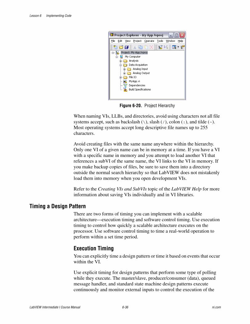
Lesson 6 Implementing Code
LabVIEW Intermediate I Course Manual 6-36 ni.com
Figure 6-20. Project Hierarchy
When naming VIs, LLBs, and directories, avoid using characters not all file systems accept, such as backslash (\), slash (/), colon (:), and tilde (~). Most operating systems accept long descriptive file names up to 255 characters.
Avoid creating files with the same name anywhere within the hierarchy. Only one VI of a given name can be in memory at a time. If you have a VI with a specific name in memory and you attempt to load another VI that references a subVI of the same name, the VI links to the VI in memory. If you make backup copies of files, be sure to save them into a directory outside the normal search hierarchy so that LabVIEW does not mistakenly load them into memory when you open development VIs.
Refer to the Creating VIs and SubVIs topic of the LabVIEW Help for more information about saving VIs individually and in VI libraries.
Timing a Design PatternThere are two forms of timing you can implement with a scalable architecture—execution timing and software control timing. Use execution timing to control how quickly a scalable architecture executes on the processor. Use software control timing to time a real-world operation to perform within a set time period.
Execution TimingYou can explicitly time a design pattern or time it based on events that occur within the VI.
Use explicit timing for design patterns that perform some type of polling while they execute. The master/slave, producer/consumer (data), queued message handler, and standard state machine design patterns execute continuously and monitor external inputs to control the execution of the

Lesson 6 Implementing Code
© National Instruments Corporation 6-37 LabVIEW Intermediate I Course Manual
design pattern. For example, the master/slave design pattern shown in Figure 6-21 uses a While Loop and a Case structure to implement the master loop.
Figure 6-21. Master/Slave Design Pattern
The master loop executes continuously and polls for an event to send a message to the slave loop. You need to time the master loop so it does not take over the execution of the processor. In this case, you typically use the Wait (ms) function to regulate how frequently the master loop polls.
Tip Always use a timing function such as the Wait (ms) function or the Wait Until Next ms Multiple function in any design pattern that continually executes and requires regulation.
Notice that the slave loop does not contain any form of timing. The use of Synchronization functions to pass messages provides an inherent form of timing in the slave loop. The slave loop waits for the Notifier function to receive a message. After the notifier receives a message, the slave loop executes on the message. This creates an efficient block diagram that does not waste processor cycles by needlessly polling for messages.
Lesson 6 Implementing Code
LabVIEW Intermediate I Course Manual 6-38 ni.com
When you implement design patterns where the timing is based on the occurrence of events, you do not have to determine the correct timing frequency because the design pattern executes only when an event occurs. In other words, the design pattern executes only when it receives an event. For example, the producer/consumer (events) VI shown in Figure 6-1 does not require any timing functions. The Event structure in the producer loop controls when the producer loop executes. The Dequeue Element function in the consumer loop waits until an item is placed in the queue, thus controlling the execution of the consumer loop. Design patterns such as the producer/consumer (events) and the user interface event handler do not require any timing because external events control their timing.
Software Control TimingMany applications that you create must be able to perform an operation within a specified number of seconds. For example, if the specifications require that the system acquire temperature data for 5 minutes, you must implement timing so that the VI continually executes for the specified time. Implementing this timing involves keeping the application executing while monitoring a real-time clock.
If you use the Wait (ms) function or the Wait Until Next ms Multiple function to perform software timing, the execution of the VI only occurs after the wait functions finish. These functions are not the preferred method for performing software control timing, especially for VIs where the system must continually execute.
For software control timing, it is important that the design pattern run continuously without stopping. If the design pattern stops executing, certain events cannot be captured, such as stopping the VI. The methods for software control timing are Get Date/Time in Seconds, Event structure timeout, and the Timed Structures.
Get Date/Time in SecondsA good pattern to use for software control timing is to cycle the current time throughout the VI, as shown in Figure 6-22.
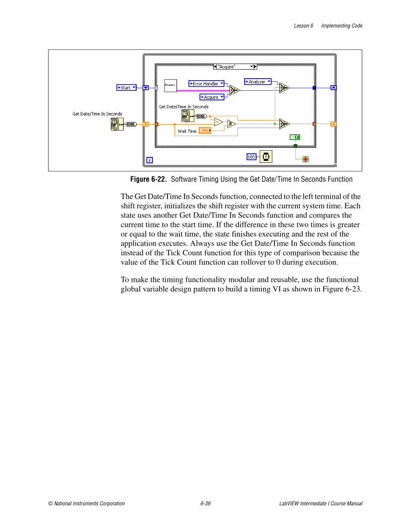
Lesson 6 Implementing Code
© National Instruments Corporation 6-39 LabVIEW Intermediate I Course Manual
Figure 6-22. Software Timing Using the Get Date/Time In Seconds Function
The Get Date/Time In Seconds function, connected to the left terminal of the shift register, initializes the shift register with the current system time. Each state uses another Get Date/Time In Seconds function and compares the current time to the start time. If the difference in these two times is greater or equal to the wait time, the state finishes executing and the rest of the application executes. Always use the Get Date/Time In Seconds function instead of the Tick Count function for this type of comparison because the value of the Tick Count function can rollover to 0 during execution.
To make the timing functionality modular and reusable, use the functional global variable design pattern to build a timing VI as shown in Figure 6-23.
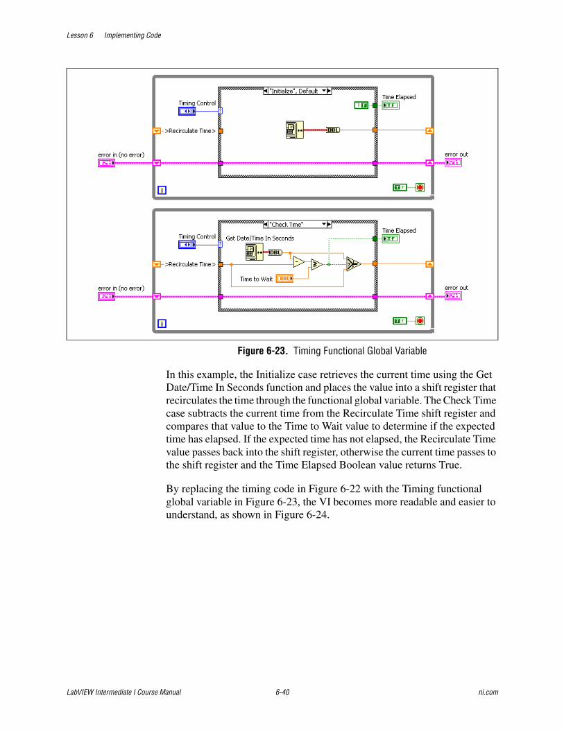
Lesson 6 Implementing Code
LabVIEW Intermediate I Course Manual 6-40 ni.com
Figure 6-23. Timing Functional Global Variable
In this example, the Initialize case retrieves the current time using the Get Date/Time In Seconds function and places the value into a shift register that recirculates the time through the functional global variable. The Check Time case subtracts the current time from the Recirculate Time shift register and compares that value to the Time to Wait value to determine if the expected time has elapsed. If the expected time has not elapsed, the Recirculate Time value passes back into the shift register, otherwise the current time passes to the shift register and the Time Elapsed Boolean value returns True.
By replacing the timing code in Figure 6-22 with the Timing functional global variable in Figure 6-23, the VI becomes more readable and easier to understand, as shown in Figure 6-24.
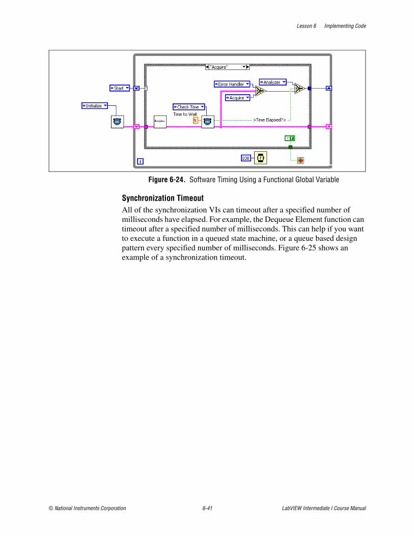
Lesson 6 Implementing Code
© National Instruments Corporation 6-41 LabVIEW Intermediate I Course Manual
Figure 6-24. Software Timing Using a Functional Global Variable
Synchronization TimeoutAll of the synchronization VIs can timeout after a specified number of milliseconds have elapsed. For example, the Dequeue Element function can timeout after a specified number of milliseconds. This can help if you want to execute a function in a queued state machine, or a queue based design pattern every specified number of milliseconds. Figure 6-25 shows an example of a synchronization timeout.
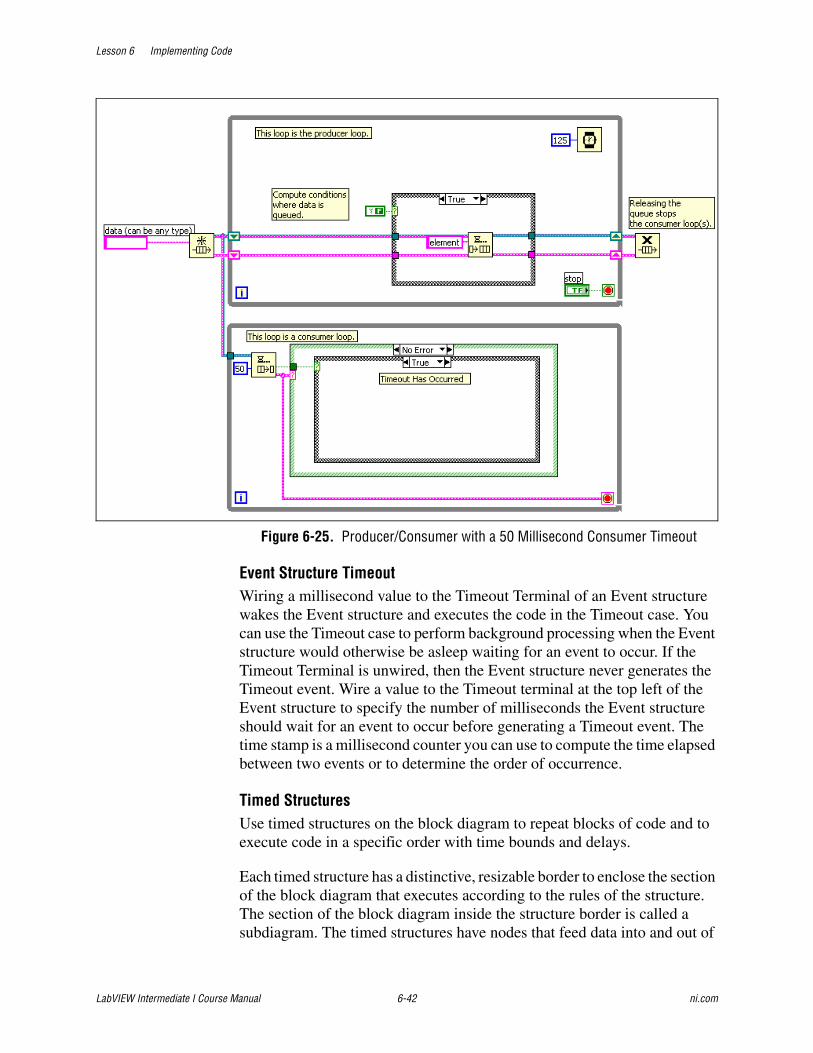
Lesson 6 Implementing Code
LabVIEW Intermediate I Course Manual 6-42 ni.com
Figure 6-25. Producer/Consumer with a 50 Millisecond Consumer Timeout
Event Structure TimeoutWiring a millisecond value to the Timeout Terminal of an Event structure wakes the Event structure and executes the code in the Timeout case. You can use the Timeout case to perform background processing when the Event structure would otherwise be asleep waiting for an event to occur. If the Timeout Terminal is unwired, then the Event structure never generates the Timeout event. Wire a value to the Timeout terminal at the top left of the Event structure to specify the number of milliseconds the Event structure should wait for an event to occur before generating a Timeout event. The time stamp is a millisecond counter you can use to compute the time elapsed between two events or to determine the order of occurrence.
Timed StructuresUse timed structures on the block diagram to repeat blocks of code and to execute code in a specific order with time bounds and delays.
Each timed structure has a distinctive, resizable border to enclose the section of the block diagram that executes according to the rules of the structure. The section of the block diagram inside the structure border is called a subdiagram. The timed structures have nodes that feed data into and out of

Lesson 6 Implementing Code
© National Instruments Corporation 6-43 LabVIEW Intermediate I Course Manual
the structures. The input and output nodes provide configuration data and return error and timing information from the structure. Timed structures also can have terminals on the structure border that feed data into and out of the structure subdiagrams.
Timed structures execute at a priority below the time-critical priority of any VI but above high priority, which means that a timed structure executes in the data flow of a block diagram ahead of any VI not configured to run at a time-critical priority.
Timed Sequence StructureThe Timed Sequence structure consists of one or more task subdiagrams, or frames, that execute sequentially. Use the Timed Sequence when you want to develop VIs with multi-rate timing capabilities, precise timing, execution feedback, timing characteristics that change dynamically, or several levels of execution priority. Right-click the structure border to add, delete, insert, and merge frames.
Double-click the Input Node to display the Configure Timed Sequence dialog box, where you can configure the Timed Sequence. The values you enter in the Configure Timed Sequence dialog box appear as options in the Input Node. You can use this dialog box to specify a timing source, set the priority, and to configure advanced options for the Timed Sequence.
The Left Data node of a Timed Sequence frame provides timing and status information about the previous and current frame, such as the expected start time, actually start time, and if the previous frame completed late. You can wire data to the Right Data node to configure the options of the next frame dynamically. Refer to the Setting the Input Options of a Timed Structure Dynamically topic of the LabVIEW Help for information about using the Data nodes to dynamically change the behavior of a Timed Sequence.
Note The Right Data node of the last frame of a Timed Sequence does not include configuration options because you do not have to configure another frame or iteration.
The Output node returns error information received in the error in input of the Input node, error information generated by the structure during execution, or error information from any task subdiagram that executes within a frame of the Timed Sequence. The Output node also returns timing and status information for the final frame.
Note Adding a VI set to time-critical priority and a Timed Sequence on the same block diagram can lead to unexpected timing behavior.
Lesson 6 Implementing Code
LabVIEW Intermediate I Course Manual 6-44 ni.com
Timed LoopThe Timed Loop executes one or more subdiagrams, or frames, sequentially each iteration of the loop at the period you specify. Use the Timed Loop when you want to develop VIs with multi-rate timing capabilities, precise timing, feedback on loop execution, timing characteristics that change dynamically, or several levels of execution priority. Right-click the structure border to add, delete, insert, and merge frames.
Double-click the Input Node or right-click the structure and select Configure Timed Loop to display the Configure Timed Loop dialog box, where you can configure the Timed Loop. The values you enter in the Configure Timed Loop dialog box appear next to the input terminals on the Input Node.
Unlike the While Loop, the Timed Loop does not require wiring to the stop terminal. If you do not wire anything to the stop terminal, the loop runs interminably.
Note Adding a VI set to time-critical priority and a Timed Loop on the same block diagram can lead to unexpected timing behavior.
The Left Data node of the Timed Loop provides timing and status information about the previous loop iteration, such as if the iteration executed late, the time the iteration actually started executing, and when the iteration should have executed. You can wire data to the Right Data node to configure the options of the next loop iteration dynamically, or you can use the Configure Next Frame Timing dialog box to enter values for the options. Refer to the Setting the Input Options of a Timed Structure Dynamically topic of the LabVIEW Help for information about using the Right Data node to dynamically change the behavior of the next iteration of a Timed Loop.
The Output node returns error information received in the Error in input of the Input node, error information generated by the structure during execution, or error information from the task subdiagram that executes within the Timed Loop. The Output node also returns timing and status information.
Timed Loop with FramesYou can add frames to a Timed Loop to execute multiple timed subdiagrams sequentially each iteration of the loop at the period you specify. A Timed Loop with frames behaves like a regular Timed Loop with an embedded Timed Sequence.
Note Adding a VI set to time-critical priority and a Timed Loop on the same block diagram can lead to unexpected timing behavior.
Lesson 6 Implementing Code
© National Instruments Corporation 6-45 LabVIEW Intermediate I Course Manual
You can set configuration options of the Timed Loop by wiring values to the inputs of the Input node, or you can use the Configure Timed Loop With Frames dialog box to enter values for the options. Refer to the Configuring Timed Loops topic of the LabVIEW Help for more information about configuring a Timed Loop with frames.
The Left Data node of a Timed Loop frame provides timing and status information about the previous loop iteration or frame. You can wire data to the Right Data node of a Timed Loop frame to configure the options of the next loop iteration dynamically, or you can use the Configure Next Frame Timing dialog box to enter values for the options. Refer to the Setting the Input Options of a Timed Structure Dynamically topic of the LabVIEW Help for information about using the Right Data nodes to dynamically change the behavior of the next frame or iteration of a Timed Loop.
The Output node returns error information received in the Error in input of the Input node, error information generated by the structure during execution, or error information from the task subdiagrams that executes within the Timed Loop frames. The Output node also returns timing and status information.
Setting Priorities of a Timed StructureThe priority of a Timed Structure specifies when the structure executes on the block diagram relative to other objects on the block diagram. Use the priority setting of a Timed Structure to write applications with multiple tasks that can preempt each other in the same VI. Each Timed Structure on the block diagram creates and runs in its own execution system that contains a single thread, so no parallel tasks can occur. The higher the priority of a Timed Structure, the higher the priority the structure has relative to other Timed Structures on the block diagram. The value for the Priority input must be a positive integer between 1 and 2,147,480,000.
You also can assign a priority for each frame of a Timed Sequence or Timed Loop with frames. LabVIEW checks the priority of any frame ready to execute and starts the frame with the highest priority.
The following block diagram contains a Timed Loop and a Timed Sequence with two frames. The Priority value of the first frame of the Timed Sequence (200) is higher than the priority of the Timed Loop (100). Because the first frame of the Timed Sequence has a higher priority, it executes first.

Lesson 6 Implementing Code
LabVIEW Intermediate I Course Manual 6-46 ni.com
After the first frame of the Timed Sequence executes, LabVIEW checks the priority of other structures or frames that are ready to execute. The priority of the Timed Loop is higher than the priority of the second frame of the Timed Sequence. LabVIEW executes an iteration of the Timed Loop and then checks the priority of the structures or frames that are ready to execute. The Timed Loop priority (100) is higher than the second frame of the Timed Sequence (50). In this example, the Timed Loop executes completely before the second frame of the Timed Sequence executes.
You can dynamically set the priority of subsequent iterations of a Timed Loop or the priority of the next frame of a Timed Loop or Sequence by wiring a value to the Priority input terminal of the Right Data node in the current frame. Refer to the Setting the Input Options of a Timed Structure Dynamically topic of the LabVIEW Help for information about dynamically configuring priority values.
Selecting a Timing Source for Timed StructuresA timing source determines when a Timed Structure executes a loop or sequence iteration. You can select from two timing sources to control the timing of a Timed Structure—internal or external. Internal timing sources are built-in timing sources that can be selected using the Configuration dialogs of a Timed Structures. External timing sources require synchronization with an external hardware target.

Lesson 6 Implementing Code
© National Instruments Corporation 6-47 LabVIEW Intermediate I Course Manual
Use the Source listbox in the Configure Timed Loop or Configure Timed Sequence dialog boxes to select an internal timing source or use the Create Timing Source VI to programmatically select an internal or external timing source.
Internal Timing SourcesInternal timing sources for controlling a Timed Structure include the 1 KHz clock of the operating system and the 1 MHz clock of a supported real-time (RT) target.
• 1 KHz Clock—By default, a Timed Structure uses the 1 kHz clock of the operating system as the timing source and can execute only once every 1 ms because that is the fastest speed at which the operating system timing source operates. All platforms that can run a Timed Structure support the 1 KHz timing source.
• 1 MHz Clock—Supported RT targets can use the functionality of microsecond timing with the 1 MHz timing source to control a Timed Structure. The supported targets include the Compact Vision System, desktops targets that have a Pentium III or IV processor, FieldPoint, Compact FieldPoint, 8140, 8170, 8186, and 8156B series controllers. If the system does not include a supported hardware device, the 1 kHz clock is the only timing source available.
• 1 KHz Clock <reset at structure start>—A timing source similar to the 1 KHz clock that resets at every iteration of a Timed Structure.
• 1 MHz Clock <reset at structure start>—A timing source similar to the 1 MHz clock that resets at every iteration of a Timed Structure.
External Timing SourcesExternal timing sources for controlling the Timed Structures include counter/timers, data acquisition sample clocks, and digital change detection. With NI-DAQmx 7.2 or later, you can use several types of timing sources to control a Timed Structure such as frequency, digital edge counters, digital change detection, and signals from task sources.
• Frequency—Creates a timing source that causes a Timed Structure to execute at a constant frequency.
• Digital Edge Counter—Creates a timing source that causes a Timed Structure to execute on rising or falling edges of a digital signal.
• Digital Change Detection—Creates a timing source that causes a Timed Structure to execute on rising and/or falling edges of one or more digital lines.
• Signal from Task—Creates a timing source that uses the signal you specify to determine when a Timed Structure executes.
Use the VIs and functions on the Timed Structures and DAQmx palettes to create external timing sources to control a Timed Structure.

Lesson 6 Implementing Code
LabVIEW Intermediate I Course Manual 6-48 ni.com
Setting a TimeoutA timeout specifies the maximum amount of time, relative to the timing source, a Timed Loop or an individual frame can wait to begin execution. Use the Input Node of a timed structure to set the timeout value for the start of the timed frame. If the execution of the subdiagram does not begin before the timing source reaches the specified timeout value, the Timed Loop returns Timeout in the Wake-up Reason output of the Left Data node.
In the following example, the first frame of the Timed Sequence takes 60 ms to complete. The second frame is configured to start 50 ms after the start of the loop and therefore must wait 10 ms. The second frame is configured with a timeout value of 5 ms before timing out and returns Timeout in the Wakeup Reason output of the Left Data node for the frame.
If a timeout occurs in a timed structure, the structure continues to execute untimed. If a Timed Loop starts the next iteration or reaches the timeout frame again, the Timed Loop waits for the same event that it was waiting for when the timeout occurred.
The default Timeout value for the Input Node is –1, which indicates to wait indefinitely for the start of the subdiagram or frame. The default Timeout value in the Left Data nodes of a frame is 0, which indicates that the timeout is unchanged and equal to the timeout of the previous frame or iteration.
Refer to the Timed Structures topic of the LabVIEW Help for more information about configuring Timed Structures.
Job AidUse the following checklist when determining the timing mechanism to use for an application.
❑ Use event-based design patterns to simplify execution timing.
❑ Use a functional global variable to perform software control timing.
Lesson 6 Implementing Code
© National Instruments Corporation 6-49 LabVIEW Intermediate I Course Manual
Exercise 6-2 Timing
GoalCreate a VI that uses the timing structures in LabVIEW to provide accurate software controlled timing.
ScenarioThe Theatre Light Controller requires accurate timing to control the cue wait, fade, and follow time. The requirements for the Theatre Light Controller require that the application respond within 100 ms when any operation is running. So when choosing a method to accurately time the Theatre Light Controller the timing method cannot interfere with the application response. The timing structures in LabVIEW provide very accurate timing. You also can control the timing structures while they are running. You use the timing structures in LabVIEW to time the Theatre Light Controller.
DesignBuild a timing module that you can use to control the timing of the Theatre Light Controller. The VI controls the timing for the wait, fade, and follow times of the Theatre Light Controller. Use the timing structures to control the timing.
This application requires a structure that has precise timing characteristics and does not use the processor. However, the structure also must respond when necessary for the wait, fade, and follow time requirements. Therefore, the Timed Loop is the best timing structure to implement these timing requirements.
A functional global variable provides for a good architecture to modularize the timing functionality. The functional global variable has the following functions:
• Initialize—Stores the timing information and structure names in the shift registers.
• Create—Creates the timing source for the timing structure.
• Wait—Waits using a Timed Loop structure specified by the number of wait seconds.
• Fade—Uses a Timed Loop to iterate at a specified update period for the number of seconds specified by the fade time.
• Follow—Waits using a Timed Loop structure specified by the number of follow seconds.
• Shutdown—Clears the timing source.
Lesson 6 Implementing Code
LabVIEW Intermediate I Course Manual 6-50 ni.com
The advantage to using the timing structures in the application is that it is very easy to stop them. Therefore, develop a VI that uses the Stop Timed Structure VI.
Implementation1. Create a new folder in the Modules folder called Timing.
2. Add the following files, located in the C:\Exercises\LabVIEW Intermediate I\Course Project\Modules\Timing directory to the Timing folder.
– tlc_Timing Command Control.ctl
– tlc_Timing Module Unit Test.vi
– tlc_Timing Module.vi
– tlc_Timing Stop Module Control.ctl
– tlc_Timing Stop Module.vi
3. Create a new folder in the My Computer project hierarchy called Shared.
4. Add Clear Specific Error.vi located in the C:\Exercises\LabVIEW Intermediate I\Course Project\Shared directory to the Shared folder.
5. Open the tlc_Timing Module.vi.

Lesson 6 Implementing Code
© National Instruments Corporation 6-51 LabVIEW Intermediate I Course Manual
6. Modify the Create case to create a timing source for the timing structures as shown in Figure 6-26.
Figure 6-26. Timer Create Case
❑ Place the Create Timing Source VI on the block diagram.
❑ Wire the output of the Create Timing Source VI to the timing source tunnel on the VI.
❑ Create and wire a string constant with the value Play Timer to the name (in) input of the Create Timing Source VI.
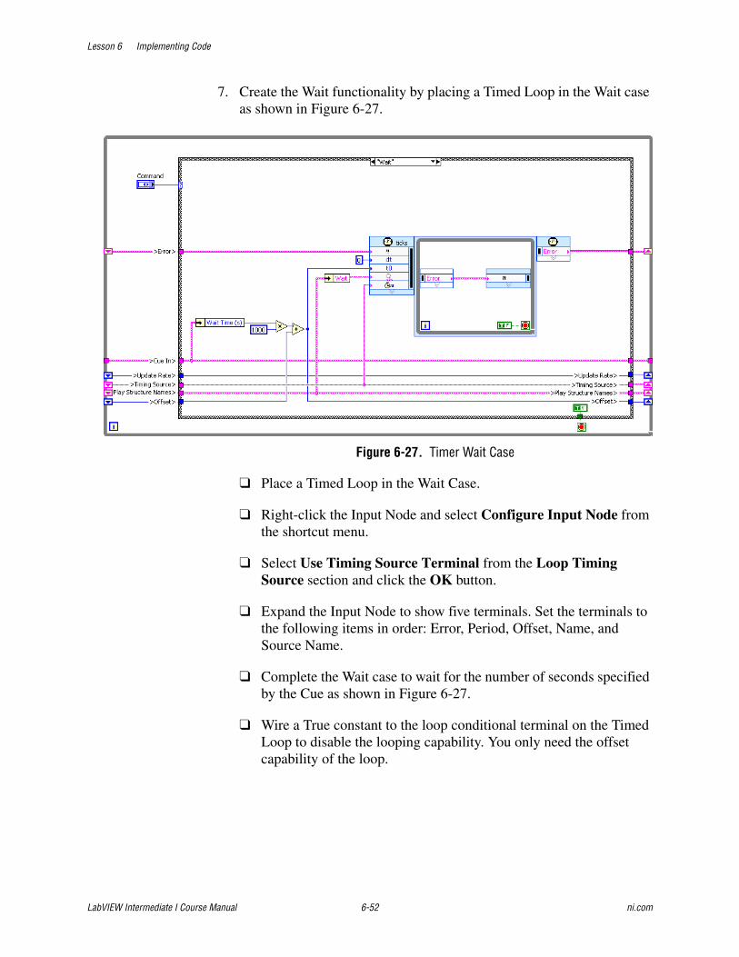
Lesson 6 Implementing Code
LabVIEW Intermediate I Course Manual 6-52 ni.com
7. Create the Wait functionality by placing a Timed Loop in the Wait case as shown in Figure 6-27.
Figure 6-27. Timer Wait Case
❑ Place a Timed Loop in the Wait Case.
❑ Right-click the Input Node and select Configure Input Node from the shortcut menu.
❑ Select Use Timing Source Terminal from the Loop Timing Source section and click the OK button.
❑ Expand the Input Node to show five terminals. Set the terminals to the following items in order: Error, Period, Offset, Name, and Source Name.
❑ Complete the Wait case to wait for the number of seconds specified by the Cue as shown in Figure 6-27.
❑ Wire a True constant to the loop conditional terminal on the Timed Loop to disable the looping capability. You only need the offset capability of the loop.
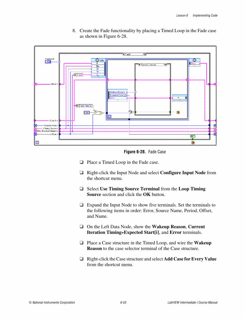
Lesson 6 Implementing Code
© National Instruments Corporation 6-53 LabVIEW Intermediate I Course Manual
8. Create the Fade functionality by placing a Timed Loop in the Fade case as shown in Figure 6-28.
Figure 6-28. Fade Case
❑ Place a Timed Loop in the Fade case.
❑ Right-click the Input Node and select Configure Input Node from the shortcut menu.
❑ Select Use Timing Source Terminal from the Loop Timing Source section and click the OK button.
❑ Expand the Input Node to show five terminals. Set the terminals to the following items in order: Error, Source Name, Period, Offset, and Name.
❑ On the Left Data Node, show the Wakeup Reason, Current Iteration Timing»Expected Start[i], and Error terminals.
❑ Place a Case structure in the Timed Loop, and wire the Wakeup Reason to the case selector terminal of the Case structure.
❑ Right-click the Case structure and select Add Case for Every Value from the shortcut menu.

Lesson 6 Implementing Code
LabVIEW Intermediate I Course Manual 6-54 ni.com
9. Stop the Timed Loop when the Fade Time has elapsed.
❑ Outside of the Timed Loop, add the Fade Time in milliseconds with the cumulative offset time.
❑ Compare if the Expected Start [i] time is greater than or equal to the Fade Time added with the cumulative offset time.
❑ Pass the result of the comparison through the Normal case of the Case structure.
10. Wiring the Wakeup Reason from the Timed Loop to the Case Structure allows the programmer to have very fine control over the operation of the Timed Loop. Modify the code to stop the Timed Loop when the Wakeup Reason is Aborted, Timing Source Error, or Timed Loop Error.
❑ Wire a True constant to the Case structure tunnel that is connected to the loop condition terminal on the Timed Loop in the following cases: Aborted, Timing Source Error, and Timed Loop Error.
11. Modify the code to keep the Timed Loop running if the Wakeup Reason is Asynchronous Wakeup, or Timeout.
❑ Wire a False constant to the Case structure tunnel that is connected to the loop condition terminal on the Timed Loop in the following cases: Asynchronous Wakeup, and Timeout.
12. Wire the error and cue data through each case.

Lesson 6 Implementing Code
© National Instruments Corporation 6-55 LabVIEW Intermediate I Course Manual
13. Create the Follow functionality by placing a Timed Loop in the Follow case as shown in Figure 6-29.
Figure 6-29. Follow Case
❑ Place a Timed Loop in the Follow case.
❑ Right-click the Input Node and select Configure Input Node from the shortcut menu.
❑ Select Use Timing Source Terminal from the Loop Timing Source section and click the OK button.
❑ Expand the Input Node to show five terminals. Set the terminals to the following items in order: Error, Period, Offset, Name, and Source Name.
❑ Complete the Follow case to wait for the number of seconds specified by the Cue as shown in Figure 6-29.
❑ Wire a True constant to the loop condition terminal on the Timed Loop disable the looping capability. You only need the offset capability of the loop.
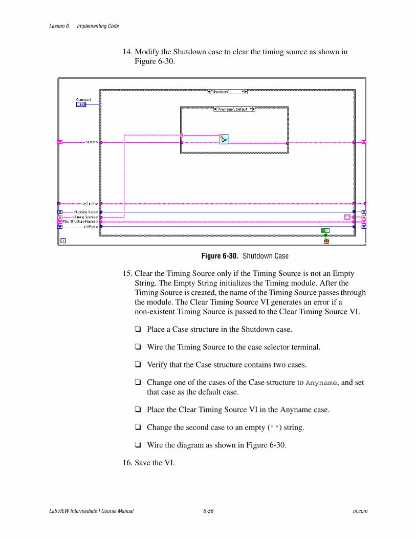
Lesson 6 Implementing Code
LabVIEW Intermediate I Course Manual 6-56 ni.com
14. Modify the Shutdown case to clear the timing source as shown in Figure 6-30.
Figure 6-30. Shutdown Case
15. Clear the Timing Source only if the Timing Source is not an Empty String. The Empty String initializes the Timing module. After the Timing Source is created, the name of the Timing Source passes through the module. The Clear Timing Source VI generates an error if a non-existent Timing Source is passed to the Clear Timing Source VI.
❑ Place a Case structure in the Shutdown case.
❑ Wire the Timing Source to the case selector terminal.
❑ Verify that the Case structure contains two cases.
❑ Change one of the cases of the Case structure to Anyname, and set that case as the default case.
❑ Place the Clear Timing Source VI in the Anyname case.
❑ Change the second case to an empty ("") string.
❑ Wire the diagram as shown in Figure 6-30.
16. Save the VI.
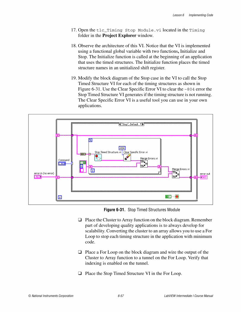
Lesson 6 Implementing Code
© National Instruments Corporation 6-57 LabVIEW Intermediate I Course Manual
17. Open the tlc_Timing Stop Module.vi located in the Timing folder in the Project Explorer window.
18. Observe the architecture of this VI. Notice that the VI is implemented using a functional global variable with two functions, Initialize and Stop. The Initialize function is called at the beginning of an application that uses the timed structures. The Initialize function places the timed structure names in an unitialized shift register.
19. Modify the block diagram of the Stop case in the VI to call the Stop Timed Structure VI for each of the timing structures as shown in Figure 6-31. Use the Clear Specific Error VI to clear the –804 error the Stop Timed Structure VI generates if the timing structure is not running. The Clear Specific Error VI is a useful tool you can use in your own applications.
Figure 6-31. Stop Timed Structures Module
❑ Place the Cluster to Array function on the block diagram. Remember part of developing quality applications is to always develop for scalability. Converting the cluster to an array allows you to use a For Loop to stop each timing structure in the application with minimum code.
❑ Place a For Loop on the block diagram and wire the output of the Cluster to Array function to a tunnel on the For Loop. Verify that indexing is enabled on the tunnel.
❑ Place the Stop Timed Structure VI in the For Loop.
Lesson 6 Implementing Code
LabVIEW Intermediate I Course Manual 6-58 ni.com
❑ Place the Clear Specific Error.vi located in the C:\Exercises\LabVIEW Intermediate I\Course Project\Shared directory on the block diagram.
❑ Place two copies of Merge Error VI on the block diagram.
❑ Create a shift register on the border of the For Loop.
❑ Place a Error Cluster constant on the block diagram and wire it to the left hand shift register.
❑ Complete the wiring of the block diagram as shown in Figure 6-31.
20. Save the VI. Do not close the VI.
TestingA unit test VI is provided to verify the functionality of the Timing module. The Unit Test VI repetitively calls the Timing module and uses the Get/Date Time in Seconds function to determine how long the execution of the Timing module takes.
1. Use the Unit Test VI to test that the Timing module returns the values you specify in the Cue control.
❑ Open tlc_Timing Module Unit Test.vi located in the Timing folder in the Project Explorer window.
❑ Observe the functionality of the Unit Test VI by examining the block diagram.
❑ Specify a value for the wait time, fade time, and follow time in the Cue control.
❑ Run the VI, and verify that the times returned match what you specified in the Cue control.
2. Test the stopping capability of the Timing module.
❑ Enter the Play Structure Names control in the tlc_Timing Module Stop.vi to have the same structure names that are specified in the tlc_Timing Module Unit Test.vi.
❑ Run the tlc_Timing Module Stop.vi with the command control set to Initialize.
❑ Run tlc_Timing Module Unit Test.vi.
Lesson 6 Implementing Code
© National Instruments Corporation 6-59 LabVIEW Intermediate I Course Manual
❑ While the tlc_Timing Module Unit Test.vi runs, run the tlc_Timing Module Stop.vi with the command control set to Stop.
❑ Verify that the timing structure that was currently executing in the tlc_Timing Module Unit Test.vi stops. Notice that the time for one of the timing periods is less than what was specified for the timing period.
End of Exercise 6-2
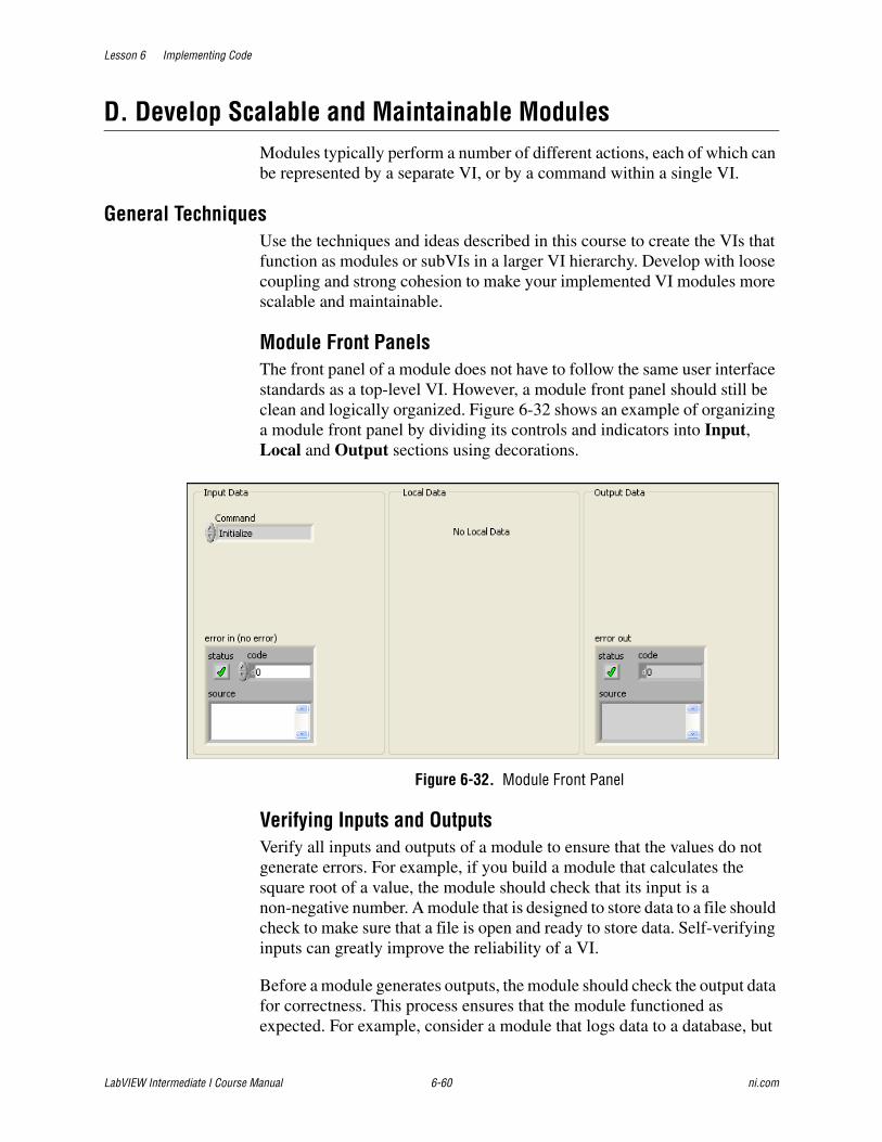
Lesson 6 Implementing Code
LabVIEW Intermediate I Course Manual 6-60 ni.com
D. Develop Scalable and Maintainable ModulesModules typically perform a number of different actions, each of which can be represented by a separate VI, or by a command within a single VI.
General TechniquesUse the techniques and ideas described in this course to create the VIs that function as modules or subVIs in a larger VI hierarchy. Develop with loose coupling and strong cohesion to make your implemented VI modules more scalable and maintainable.
Module Front PanelsThe front panel of a module does not have to follow the same user interface standards as a top-level VI. However, a module front panel should still be clean and logically organized. Figure 6-32 shows an example of organizing a module front panel by dividing its controls and indicators into Input, Local and Output sections using decorations.
Figure 6-32. Module Front Panel
Verifying Inputs and OutputsVerify all inputs and outputs of a module to ensure that the values do not generate errors. For example, if you build a module that calculates the square root of a value, the module should check that its input is a non-negative number. A module that is designed to store data to a file should check to make sure that a file is open and ready to store data. Self-verifying inputs can greatly improve the reliability of a VI.
Before a module generates outputs, the module should check the output data for correctness. This process ensures that the module functioned as expected. For example, consider a module that logs data to a database, but
Lesson 6 Implementing Code
© National Instruments Corporation 6-61 LabVIEW Intermediate I Course Manual
has no inherent verification that the data was logged correctly. You must explicitly create a mechanism to determine that the module correctly stored the data in the database, such as reading the value back from the database and checking it against the original value.
Handling ErrorsWhenever possible, correct any errors that occur in a module within the module where the error occurs. When you cannot correct an error within the module, return the error to the calling VI so that the calling VI can correct, ignore, or display the error to the user. When you implement a module, make sure the module handles any errors that it can. Include error clusters to pass error information into and out of the module.
Developing Modules Using Organized SubVIsOne technique for developing a module is to create a set of related subVIs that perform each of the functions required of the module. Some advantages of this approach are that you can add and remove functions from the module. Some functions also may be reusable as subVIs outside of the module. Disadvantages include the need to create and document a large number of subVIs and large number of files to manage and maintain. When you use multiple subVIs, more than one function from a module can be called at the same time. This is an advantage or a disadvantage depending upon the behavior of the module.
Using a Consistent StyleUse a consistent style when implementing each VI in your module. Also use a consistent naming convention for each VI, and include the name of the module as part of the VI name. Use a consistent front panel design for each VI, such as the one described in the Module Front Panels section. Use a consistent pattern and color scheme for the VI icons. Also use a consistent connector pane, whenever possible, so that you can cleanly wire together different VIs in the same module. A good technique for accomplishing all of this is to create a template for your module, which has the front panel, part of the VI icon, a connector pane pattern, and any other common elements already implemented.
Organizing Files on DiskCreate a directory on disk for each module. This, along with an appropriate VI naming scheme, helps you to differentiate VIs that belong to one module from VIs that belong to another. The root module directory contains the VIs for each of the module functions specified in your design. Include additional VIs that the module functions call in one or more subdirectories. Also, place any controls the module uses in subdirectories. Store any VIs or controls used by multiple modules in a central location, such as a shared or utility directory.
Lesson 6 Implementing Code
LabVIEW Intermediate I Course Manual 6-62 ni.com
Using LibrariesLabVIEW Libraries are a powerful tool for organizing your modules. If you are using libraries, include each module in its own library. Using a library provides a number of benefits. First, a library allows you to clearly differentiate between top-level VIs which should be called by external code, and low-level VIs which the module uses as subVIs. The ability to mark VIs in a library as public and private allows you to specify that no VI outside of the module can call one of the low-level VIs, preventing confusion for programmers using the module. Marking VIs as public or private also allows you to make assumptions or requirements about the use of a private VI that might not otherwise be safe. Libraries also create a namespace for your module, thereby preventing difficulties if VIs in your module have the same name as other VIs in memory. This feature is particularly useful when distributing modules for use in an unknown environment. Finally, libraries abstract your module from other VIs and allow you to easily organize your modules within the project space.
Developing Modules Using a Multi-Functional VIOne way to develop modules with loose coupling and strong cohesion is to use a multi-functional VI. A common design of a multi-functional VI consists of a Case structure controlled by an enumerated control. The enumerated type control defines commands which correspond to each function of the module. Each command is implemented by a case in the Case structure and can call lower level subVIs as necessary.
The multi-functional VI design has several advantages. It improves the readability of your code because the command is obvious when the subVI is called. You also can expand this module design to a state machine to allow for local data storage or automatic command execution. Finally, this module design prevents you from having to create and manage a subVI for each function. The disadvantages of this module design are that it is more difficult to add and remove functions from the module, because the same VI is called from everywhere that uses the module. Modifying one function can also have an effect on other functions, especially if the multi-functional VI uses a state machine design. Multi-functional VIs are non-reentrant VIs, which means that only a single function within the module can be active at any given time.
Controlling the ModuleUsing an enumerated type control for the command input into a module clearly indicates the functionality of the module. This also makes it much easier for you to reuse the module in other applications. You should always create a type definition for the enumerated type control so that you can add, remove, or rename the commands in a module without having to update each instance of the enumerated type control.
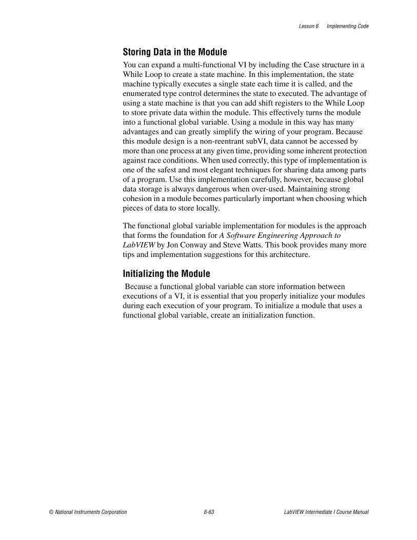
Lesson 6 Implementing Code
© National Instruments Corporation 6-63 LabVIEW Intermediate I Course Manual
Storing Data in the ModuleYou can expand a multi-functional VI by including the Case structure in a While Loop to create a state machine. In this implementation, the state machine typically executes a single state each time it is called, and the enumerated type control determines the state to executed. The advantage of using a state machine is that you can add shift registers to the While Loop to store private data within the module. This effectively turns the module into a functional global variable. Using a module in this way has many advantages and can greatly simplify the wiring of your program. Because this module design is a non-reentrant subVI, data cannot be accessed by more than one process at any given time, providing some inherent protection against race conditions. When used correctly, this type of implementation is one of the safest and most elegant techniques for sharing data among parts of a program. Use this implementation carefully, however, because global data storage is always dangerous when over-used. Maintaining strong cohesion in a module becomes particularly important when choosing which pieces of data to store locally.
The functional global variable implementation for modules is the approach that forms the foundation for A Software Engineering Approach to LabVIEW by Jon Conway and Steve Watts. This book provides many more tips and implementation suggestions for this architecture.
Initializing the Module Because a functional global variable can store information between executions of a VI, it is essential that you properly initialize your modules during each execution of your program. To initialize a module that uses a functional global variable, create an initialization function.
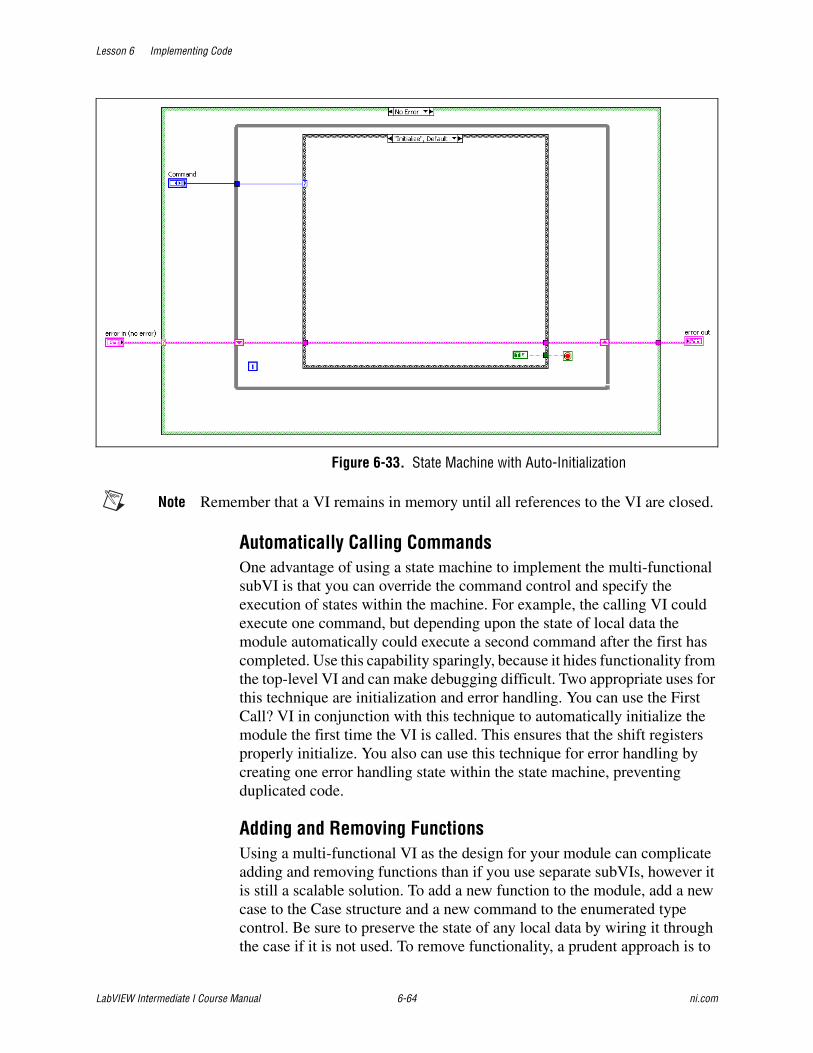
Lesson 6 Implementing Code
LabVIEW Intermediate I Course Manual 6-64 ni.com
Figure 6-33. State Machine with Auto-Initialization
Note Remember that a VI remains in memory until all references to the VI are closed.
Automatically Calling CommandsOne advantage of using a state machine to implement the multi-functional subVI is that you can override the command control and specify the execution of states within the machine. For example, the calling VI could execute one command, but depending upon the state of local data the module automatically could execute a second command after the first has completed. Use this capability sparingly, because it hides functionality from the top-level VI and can make debugging difficult. Two appropriate uses for this technique are initialization and error handling. You can use the First Call? VI in conjunction with this technique to automatically initialize the module the first time the VI is called. This ensures that the shift registers properly initialize. You also can use this technique for error handling by creating one error handling state within the state machine, preventing duplicated code.
Adding and Removing FunctionsUsing a multi-functional VI as the design for your module can complicate adding and removing functions than if you use separate subVIs, however it is still a scalable solution. To add a new function to the module, add a new case to the Case structure and a new command to the enumerated type control. Be sure to preserve the state of any local data by wiring it through the case if it is not used. To remove functionality, a prudent approach is to
Lesson 6 Implementing Code
© National Instruments Corporation 6-65 LabVIEW Intermediate I Course Manual
delete the case that implements the functionality without deleting the item in the enumerated type control that corresponds to that case. This allows you to verify that external VIs that call the module no longer need that state.
Develop for Performance and Memory EfficiencyAlthough you want to create efficient VIs that do not cause the computer to hang when they run, performance and memory efficiency should not be your highest priority during the implementation phase. It is more important that your VIs be scalable, readable, and maintainable. Refer to Lesson 8, Evaluating VI Performance, for more information about evaluating and improving performance.
Job AidUse the following checklist when you implement your code.
❑ Avoid creating extremely large block diagrams. Limit the scrolling necessary to see the entire block diagram to one direction.
❑ Make sure data flows from left to right and wires enter from the left and exit to the right.
❑ Use free labels to document algorithms that you use on the block diagrams. If you use an algorithm from a book or other reference, provide the reference information.
❑ While LabVIEW code can be self-documenting because it is graphical, use free labels to describe how the block diagram functions.
❑ Organize VIs in a hierarchical directory with easily accessible top-level VIs and subVIs in subdirectories.
❑ Consider using functional global variables instead of global variables. Functional global variables do not create extra copies of data and allow certain actions, such as initialize, read, write, and empty. They also eliminate race conditions.
❑ Align and distribute functions, terminals, and constants.
❑ Avoid placing block diagram objects, such as subVIs or structures, on top of wires, and do not wire behind objects.
❑ Use path constants instead of string constants to specify the location of files or directories.
❑ Make good use of reusable, testable subVIs.
❑ Use error in and error out clusters in all subVIs.
Lesson 6 Implementing Code
LabVIEW Intermediate I Course Manual 6-66 ni.com
❑ Make sure the program can deal with error conditions and invalid values.
❑ Show name of source code or include source code for any CINs.
❑ Use sequence structures sparingly because they hide code. If flow-through parameters are not available and you must use a sequence structure in the VI, consider using a Flat Sequence structure.
❑ Save the VI with the most important frame of multiframed structures—Case, Stacked Sequence, and Event structures—showing.
❑ Review the VI for efficiency, data copying, and accuracy, especially parts without data dependency.
❑ Make sure the subVI icon, rather than the connector pane, is visible on the block diagram.
❑ Use a type definition when you use the same unique control in more than one location or when you have a very large data structure passing between several subVIs.
❑ If you open references to a LabVIEW object, such as an application, control, or VI, close the references by using the Close Reference function. It is good practice to close any reference you open programmatically.
❑ Make sure the Name Format for Property Nodes and Invoke Nodes is set to Short Names to ensure the best readability of the block diagram.
❑ Make sure control and indicator terminals on the connector pane are not inside structures on the block diagram.

Lesson 6 Implementing Code
© National Instruments Corporation 6-67 LabVIEW Intermediate I Course Manual
Exercise 6-3 Implement Code
GoalObserve and implement the VIs that you identified as modules for the application.
ScenarioWhen you carefully plan and design an application, your implementation of the system creates scalable, readable, and maintainable VIs. Implement the Display, File, and Hardware modules. These are the major modules that you identified for the Theatre Light Control Software application. You have already implemented the Cue and Timing modules.
DesignThe functional global variable approach you used to implement the cue and timing modules provides for a very scalable, readable, and maintainable method to build VIs. Continue to use a functional global variable to implement the remaining modules for the application.
DisplayThe tight coupling that exists between the front panel and block diagram in a VI requires that you update the front panel using terminals on the VI block diagram, or use references from a subVI. Each of these methods has its advantages and disadvantages. Updating a front panel directly using a terminal is a very fast and efficient method of updating front panel controls and indicators. However, you must have a way to get subVI data to the top-level VI to update the front panel. You can loosed the tight coupling that exists between the front panel and the block diagram by sending a message from subVIs to the top-level VI that contains that control and indicator. An ideal implementation for this is a functional global variable.
LabVIEW is inherently a parallel programming language. You can take advantage of the parallelism by using a separate loop to update the user interface. The separate loop contains a queue that stores commands to perform inside the loop. You can use a functional global variable to control the separate loop from anywhere in the application by placing commands in the queue.
The display module uses a functional global variable to store the reference for the display queue. This allows the module to be called from anywhere in the application to control the separate display loop.
Lesson 6 Implementing Code
LabVIEW Intermediate I Course Manual 6-68 ni.com
FileThe file module calls the File I/O VIs. The file module provides the functionality to initialize, load cues from a file, save cues to a file, and shutdown. Implement the file module using the functional global variable architecture.
HardwareThe hardware module calls the Theatre Light Control API. The hardware module provides the functionality to initialize, write, and shutdown the hardware.
Implementation
DisplayThe Display module provides a method to update the front panel controls and indicators from anywhere in the application. This module populates a queue that contains commands to perform and the data for the commands. The display module performs the Initialize Front Panel, Update Front Panel Channels, Select Cue in Cue List, Enable/Disable Front Panel Controls, and Update Cue List functions.
To build a system that can perform these functions, you first must modify the design pattern in TLC Main VI to have a third loop, and then create a display module that is a functional global variable to send messages to the third loop.
A queue that is specifically for the display loop controls the third loop. The third loop only updates the user interface in the top-level VI.
Design Pattern Modification1. Open the TLC Main VI.
2. Open the block diagram.
3. Modify the block diagram to have three loops. Create another queue to pass data to the display loop as shown in Figure 6-34.
❑ Place a While Loop on the block diagram.
❑ Place a Case Structure inside the While Loop.
❑ Place the Unbundle By Name function inside the While Loop.
Lesson 6 Implementing Code
© National Instruments Corporation 6-69 LabVIEW Intermediate I Course Manual
4. Create a queue to control the new While Loop.
❑ Add tlc_User Interface Command.ctl located in the C:\Exercises\LabVIEW Intermediate I\Course Project\Controls directory to the project and place the control as a constant on the block diagram. This constant uses an enumerated type control and variant inside a cluster to provide a scalable data type for the third loop.
❑ Place the Obtain Queue function on the block diagram.
❑ Wire the tlc_User Interface Command.ctl constant to the Obtain Queue function.
❑ Place the Enqueue Element function on the block diagram.
❑ Set the tlc_User Interface Command.ctl enum to Initialize and wire the constant to the Enqueue Element function.
❑ Place the Dequeue Element function in the While Loop.
❑ Wire the Queue reference and the error cluster as shown in Figure 6-34.
❑ Wire the element output of the Dequeue Element function to the Unbundle by Name function.
❑ Wire the Data Type element to the case selector terminal.
❑ Right-click the Case structure and select Add Case for Every Value from the shortcut menu.
❑ Wire a False constant to the loop conditional terminal inside each case of the Case structures. Set the constant to True in the Stop case.
❑ Place the Release Queue function on the block diagram to close the Display loop queue references.
❑ Complete the wiring on the block diagram by wiring the Queue reference and error cluster through each case on the case structure. Also, wire the Queue reference to the Release Queue function and wire the error cluster from the third loop as shown in Figure 6-34.
5. Create a custom control for the queue reference that the Obtain Queue function generates on the third loop. You use this reference to enqueue items from within subVIs.

Lesson 6 Implementing Code
LabVIEW Intermediate I Course Manual 6-70 ni.com
Figu
re 6
-34.
Dis
play
Loo
p
Lesson 6 Implementing Code
© National Instruments Corporation 6-71 LabVIEW Intermediate I Course Manual
❑ Right-click the queue out terminal of the Obtain Queue function and select Create»Control from the shortcut menu to create the reference.
❑ Double-click the queue out reference to locate the object on the front panel.
❑ Right-click the control and select Advanced»Customize from the shortcut menu to open the Control Editor.
❑ Label the control tlc_Display Queue Reference.ctl.
❑ Select Type Def. from the Type Def. Status pull-down menu.
❑ Close the Control Editor and save the control as tlc_Display Queue Reference.ctl in the C:\Exercises\LabVIEW Intermediate I\Course Project\Controls directory.
❑ Move the tlc_Display Queue Reference.ctl control into the Controls folder in the Project Explorer window.
❑ Delete the control from TLC Main VI. You use this custom control reference when you build the Display Module.
Display ModuleCreate a module that stores which function to perform on the display. As the application runs, update the display. Complete the following steps to create the Display module.
1. Create a Display folder in the Modules project hierarchy.
2. Add tlc_Display Module.vi and tlc_Display Command Control.ctl located in the C:\Exercises\LabVIEW Intermediate I\Course Project\Modules\Display directory to the Display folder.
3. Open the tlc_Display Module.vi that you just added into the LabVIEW project.
4. Complete the front panel of the Display module, shown in Figure 6-35.
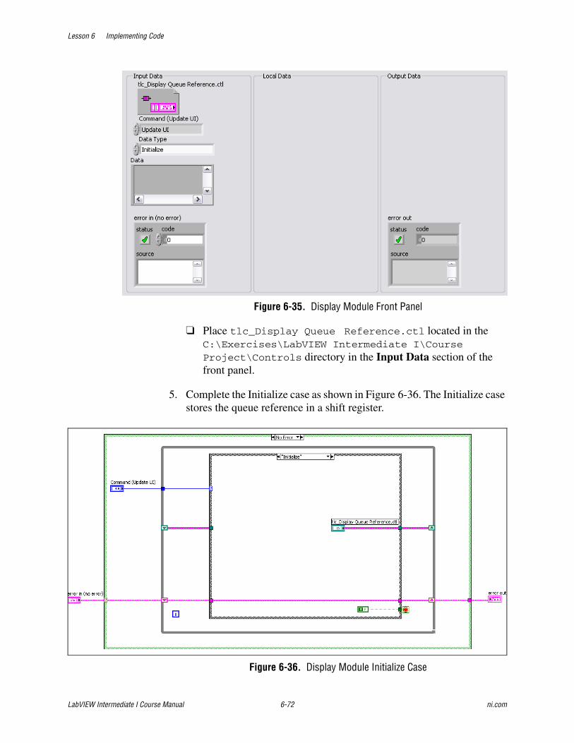
Lesson 6 Implementing Code
LabVIEW Intermediate I Course Manual 6-72 ni.com
Figure 6-35. Display Module Front Panel
❑ Place tlc_Display Queue Reference.ctl located in the C:\Exercises\LabVIEW Intermediate I\Course Project\Controls directory in the Input Data section of the front panel.
5. Complete the Initialize case as shown in Figure 6-36. The Initialize case stores the queue reference in a shift register.
Figure 6-36. Display Module Initialize Case
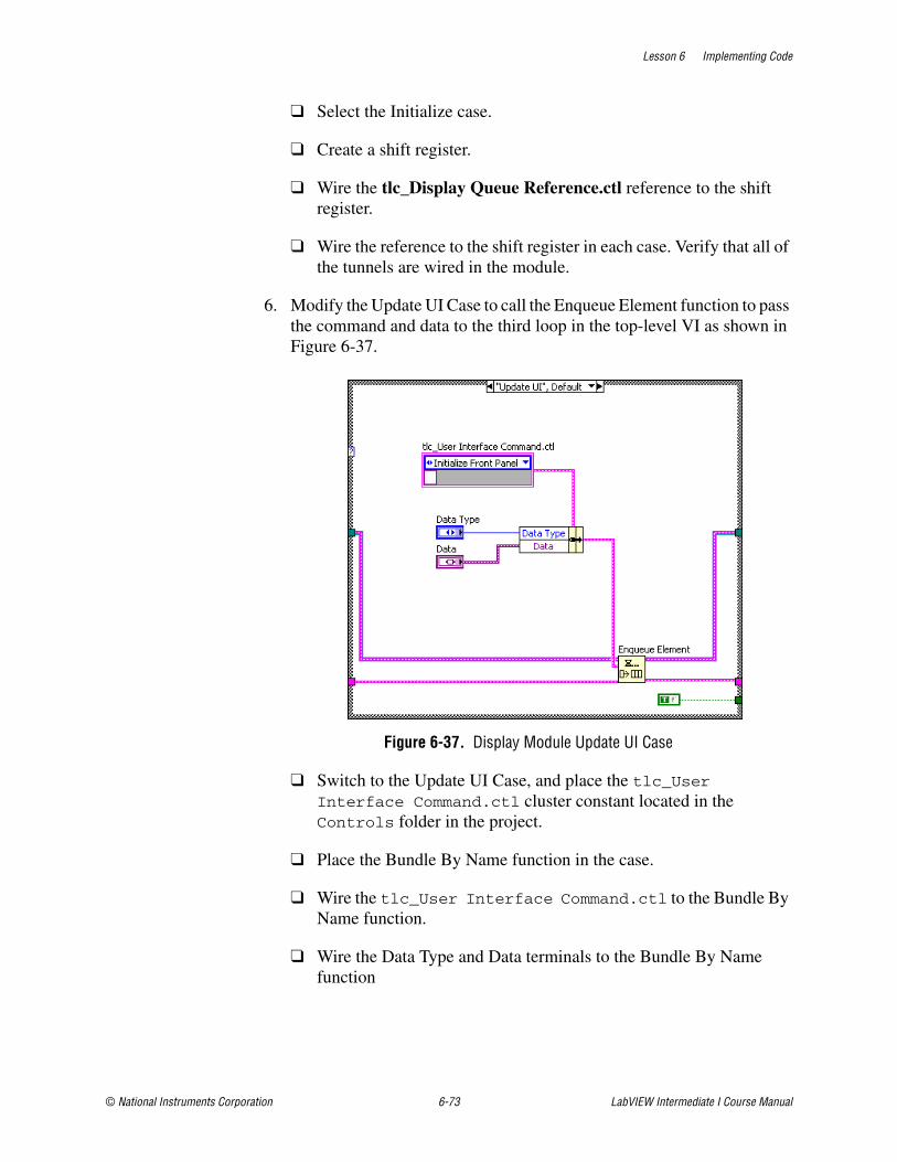
Lesson 6 Implementing Code
© National Instruments Corporation 6-73 LabVIEW Intermediate I Course Manual
❑ Select the Initialize case.
❑ Create a shift register.
❑ Wire the tlc_Display Queue Reference.ctl reference to the shift register.
❑ Wire the reference to the shift register in each case. Verify that all of the tunnels are wired in the module.
6. Modify the Update UI Case to call the Enqueue Element function to pass the command and data to the third loop in the top-level VI as shown in Figure 6-37.
Figure 6-37. Display Module Update UI Case
❑ Switch to the Update UI Case, and place the tlc_User Interface Command.ctl cluster constant located in the Controls folder in the project.
❑ Place the Bundle By Name function in the case.
❑ Wire the tlc_User Interface Command.ctl to the Bundle By Name function.
❑ Wire the Data Type and Data terminals to the Bundle By Name function
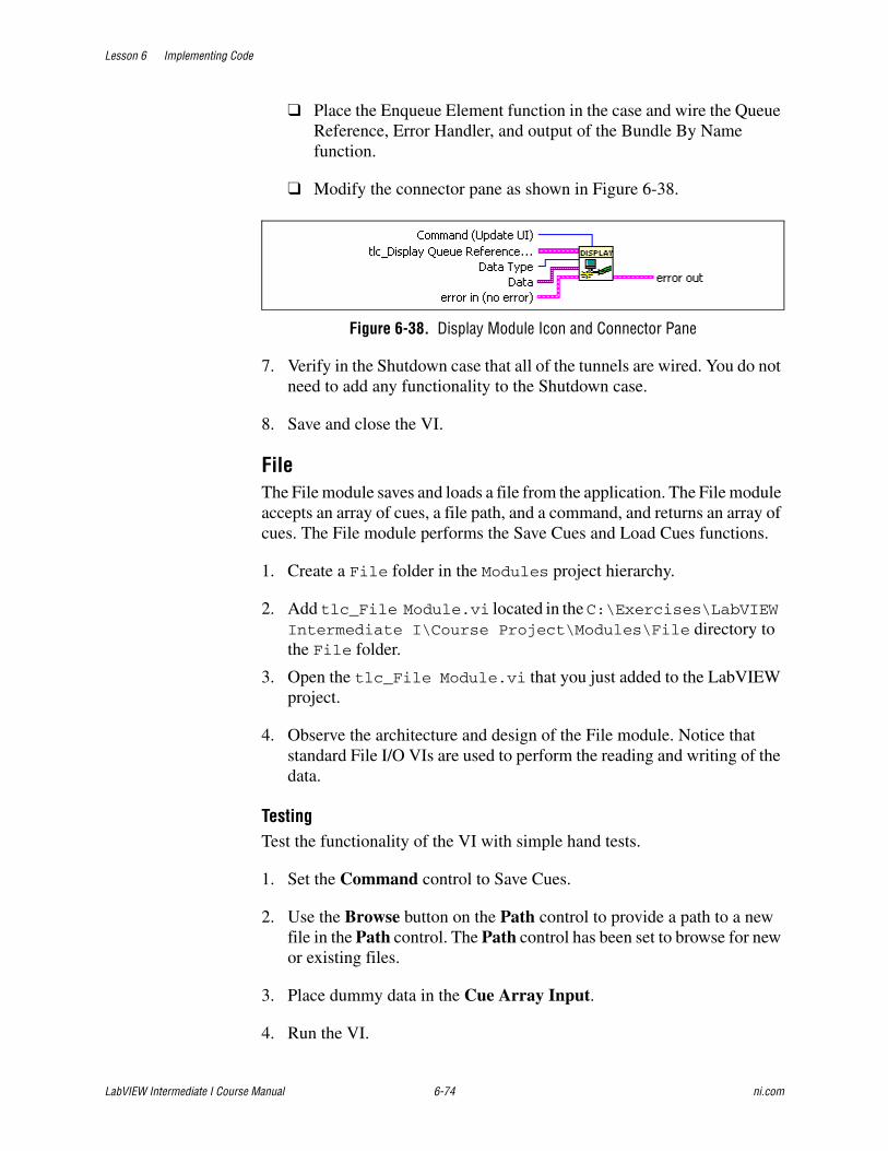
Lesson 6 Implementing Code
LabVIEW Intermediate I Course Manual 6-74 ni.com
❑ Place the Enqueue Element function in the case and wire the Queue Reference, Error Handler, and output of the Bundle By Name function.
❑ Modify the connector pane as shown in Figure 6-38.
Figure 6-38. Display Module Icon and Connector Pane
7. Verify in the Shutdown case that all of the tunnels are wired. You do not need to add any functionality to the Shutdown case.
8. Save and close the VI.
FileThe File module saves and loads a file from the application. The File module accepts an array of cues, a file path, and a command, and returns an array of cues. The File module performs the Save Cues and Load Cues functions.
1. Create a File folder in the Modules project hierarchy.
2. Add tlc_File Module.vi located in the C:\Exercises\LabVIEW Intermediate I\Course Project\Modules\File directory to the File folder.
3. Open the tlc_File Module.vi that you just added to the LabVIEW project.
4. Observe the architecture and design of the File module. Notice that standard File I/O VIs are used to perform the reading and writing of the data.
TestingTest the functionality of the VI with simple hand tests.
1. Set the Command control to Save Cues.
2. Use the Browse button on the Path control to provide a path to a new file in the Path control. The Path control has been set to browse for new or existing files.
3. Place dummy data in the Cue Array Input.
4. Run the VI.

Lesson 6 Implementing Code
© National Instruments Corporation 6-75 LabVIEW Intermediate I Course Manual
5. Set the Command control to Load Cues.
6. Run the VI.
7. Verify that the Cue Array Output matches the data that you placed in the Cue Array Input.
8. Close the VI.
HardwareThe Hardware module interacts with the Theatre Light Control API. The Hardware module performs the Write Color and Intensity function.
1. Create a Hardware folder in the Modules project hierarchy.
2. Add tlc_Hardware Module.vi located in the C:\Exercises\LabVIEW Intermediate I\Course Project\Modules\Hardware directory to the Hardware folder.
3. Open the tlc_Hardware Module.vi that you just added into the LabVIEW project.
4. Observe the architecture and design of the hardware module. Notice that the VI calls the Theatre Light Control API.
5. Close the VI.
End of Exercise 6-3

Lesson 6 Implementing Code
LabVIEW Intermediate I Course Manual 6-76 ni.com
E. Implement an Error Handling StrategyThe first goal of an error handling strategy is to determine if an error occurs. There are many ways to determine if an error occurred within a VI. When you use the state machine design pattern, you can add error handling states to the state machine. For each state in the state machine, create a corresponding error state that checks for and handles errors. The error states provide the highest level of scalability for determining if errors occur.
The next goal of an error handling strategy is to determine what action to take if a VI generates an error. Because each VI performs different functions, each VI handles errors differently. Therefore no single error handling solution works for every VI. To implement an effective error handling strategy, you must understand the functionality of the VI. There are two typical strategies for handling errors—passing the error outside the VI or using a dialog box to inform the user of the error.
Passing an error outside the VI can be ineffective for code with loose coupling because an external routine handles the error. Use this error handling strategy for VIs that are part of an application program interface (API). Many of the built-in LabVIEW VIs and functions pass the error information out of the VI or function when an error occurs. For example, if an error occurs in a File I/O VIs, LabVIEW passes the error out of the VI. It is impractical for an API VI to display a dialog box when an error occurs unless displaying a dialog box is a specific feature of that API function. For a set of API VIs, you can create specific error handling code that filters out expected errors or loops until a specific error is resolved.
When you implement an API VI, place an error handling Case structure around the API code. Wire an error cluster to the selector terminal of a Case structure to create two cases, Error and No Error. The border of the Case structure is red for Error and green for No Error. If an error occurs, the Case structure executes the Error subdiagram. This is an effective error handling strategy for VIs that function as APIs, as shown in Figure 6-33.
The second strategy informs the user of an error by displaying a meaningful dialog box. This strategy indicates the error to the user, provides a meaningful description of the error, and a resolution to the error. Use a modified General Error Handler VI to provide a meaningful dialog box to the user. The General Error Handler VI indicates if an error occurred. If an error occurred, the General Error Handler VI returns a description of the error and optionally displays a dialog box. Modify the General Error Handler VI as described in the Error Codes section of Lesson 4, Designing the Project, to create an error handler that is specific to the VI. This allows you to control when errors display and how to handle the errors.
Lesson 6 Implementing Code
© National Instruments Corporation 6-77 LabVIEW Intermediate I Course Manual
Exercise 6-4 Implement Error Handling Strategy
GoalDevelop a module that handles the errors in the application.
ScenarioHandling errors is an important part of developing applications in LabVIEW. When you are developing the application, you can use error handling to help find bugs in the applications.
A good error handling strategy is to call a module that stores the error information and safely stops the application if an error occurs.
DesignUsing a functional global variable, store the error information in an uninitialized shift register. If an error occurs, the VI sends a stop message to the producer to shut the program down.
Implementation1. Create a Error folder in the Modules project hierarchy.
2. Add the following files located in the C:\Exercises\LabVIEW Intermediate I\Course Project\Modules\Error directory to the Error folder:
– tlc_Error Module.vi
– tlc_Error Module Command Control.ctl
3. Open the tlc_Error Module.vi that you added to the LabVIEW project.
4. Modify the front panel of the VI to pass the Queue and User Event References as an Input as shown in Figure 6-39.
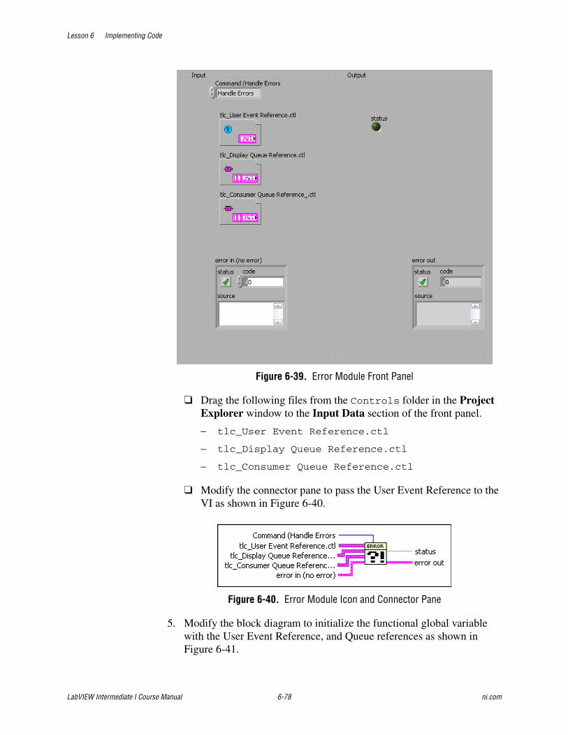
Lesson 6 Implementing Code
LabVIEW Intermediate I Course Manual 6-78 ni.com
Figure 6-39. Error Module Front Panel
❑ Drag the following files from the Controls folder in the Project Explorer window to the Input Data section of the front panel.
– tlc_User Event Reference.ctl
– tlc_Display Queue Reference.ctl
– tlc_Consumer Queue Reference.ctl
❑ Modify the connector pane to pass the User Event Reference to the VI as shown in Figure 6-40.
Figure 6-40. Error Module Icon and Connector Pane
5. Modify the block diagram to initialize the functional global variable with the User Event Reference, and Queue references as shown in Figure 6-41.
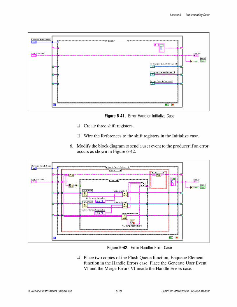
Lesson 6 Implementing Code
© National Instruments Corporation 6-79 LabVIEW Intermediate I Course Manual
Figure 6-41. Error Handler Initialize Case
❑ Create three shift registers.
❑ Wire the References to the shift registers in the Initialize case.
6. Modify the block diagram to send a user event to the producer if an error occurs as shown in Figure 6-42.
Figure 6-42. Error Handler Error Case
❑ Place two copies of the Flush Queue function, Enqueue Element function in the Handle Errors case. Place the Generate User Event VI and the Merge Errors VI inside the Handle Errors case.
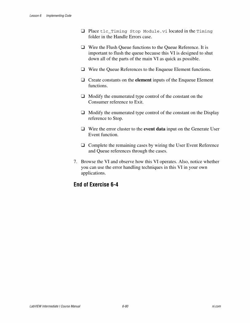
Lesson 6 Implementing Code
LabVIEW Intermediate I Course Manual 6-80 ni.com
❑ Place tlc_Timing Stop Module.vi located in the Timing folder in the Handle Errors case.
❑ Wire the Flush Queue functions to the Queue Reference. It is important to flush the queue because this VI is designed to shut down all of the parts of the main VI as quick as possible.
❑ Wire the Queue References to the Enqueue Element functions.
❑ Create constants on the element inputs of the Enqueue Element functions.
❑ Modify the enumerated type control of the constant on the Consumer reference to Exit.
❑ Modify the enumerated type control of the constant on the Display reference to Stop.
❑ Wire the error cluster to the event data input on the Generate User Event function.
❑ Complete the remaining cases by wiring the User Event Reference and Queue references through the cases.
7. Browse the VI and observe how this VI operates. Also, notice whether you can use the error handling techniques in this VI in your own applications.
End of Exercise 6-4
Lesson 6 Implementing Code
© National Instruments Corporation 6-81 LabVIEW Intermediate I Course Manual
Summary• Protect your time investment using Source Code Control tools.
• When you implement a chosen design pattern to create a scalable architecture, consider how you want to initialize the VI, provide for a timing mechanism, and document the VI.
• Use efficient timing mechanisms when you implement a scalable architecture.
• Develop with loose coupling and strong cohesion to make your implemented VI modules more scalable and maintainable.
• Follow LabVIEW style guidelines when you develop code and interfaces.

Lesson 6 Implementing Code
LabVIEW Intermediate I Course Manual 6-82 ni.com
Notes
© National Instruments Corporation 7-1 LabVIEW Intermediate I Course Manual
7Implementing a Test Plan
Now that the project is complete, you implement the test plan. Use techniques described in this lesson to verify code, test individual VIs, test the integration of individual VIs into a larger system, and test the entire system for functionality, performance, reliability, and usability.
Topics
A. Verifying the Code
B. Implementing a Test Plan for Individual VIsC. Implementing a Test Plan for Integrating VIs
D. Implementing a Test Plan for the System
Lesson 7 Implementing a Test Plan
LabVIEW Intermediate I Course Manual 7-2 ni.com
A. Verifying the CodeIt is often said that the best way to find a solution to a problem is to ask someone who knows absolutely nothing about the problem you are trying to solve. This also is true when you are developing software. When you develop a VI, you can lose objectivity about the code you produce. The best way to determine that the code is correct is to perform code reviews.
Code ReviewsA code review is similar to a design review except that it analyzes the code instead of the design. To perform a code review, give one or more developers printouts of the VIs to review. You also can perform the review online because VIs are easier to read and navigate online. Talk through the design and compare the description to the actual implementation. Consider many of the same issues included in a design review. During a code review, ask and answer some of the following questions:
• What happens if a specific VI or function returns an error? Are errors dealt with and/or reported correctly?
• Are there any race conditions? A race condition is a block diagram that reads from and writes to a global variable. A parallel block diagram has the potential to simultaneously attempt to manipulate the same global variable, resulting in loss of data.
• Is the block diagram implemented well? Are the algorithms efficient in terms of speed and/or memory usage?
• Is the block diagram easy to maintain? Does the developer make good use of hierarchy, or is he placing too much functionality in a single VI? Does the developer adhere to established guidelines?
There are a number of other features you can look for in a code review. Take notes on the problems you encounter and add them to a list you can use as a guideline for other walk-throughs.
Focus on technical issues when doing a code review. Remember to review only the code, not the developer who produced it. Do not focus only on the negative; be sure to raise positive points as well.
B. Implementing a Test Plan for Individual VIsIt is essential to test each module as you complete it. But how do you know what to test and if the tests you perform are appropriate? Because there are so many possible inputs for a VI, it can be incredibly difficult to determine if a VI has been built correctly and works as you intended. Testing every possible combination of inputs is an inefficient and ineffective strategy. The excessive computation time such a test would require is impractical. A more
Lesson 7 Implementing a Test Plan
© National Instruments Corporation 7-3 LabVIEW Intermediate I Course Manual
effective strategy is to develop test cases that can identify the largest number of errors in the application. The goal of a good test plan is to find the majority of the errors.
The individual component VI you want to test is referred to as the unit under test (UUT). You must perform unit testing before you perform system integration testing. System integration testing evaluates how your VIs perform with devices and software external to LabVIEW. The output of unit testing is useful in performing system integration because it provides structure information about the LabVIEW code. Use unit testing as one of the many tools, methods, and activities to help ensure quality software.
Creating a Test Plan for Individual VIsYou should design a test plan for each module before you build any VIs. Developing a test plan before you build a VI helps you know exactly what the VI should accomplish. The test plan also helps you understand the expected inputs and outputs to each VI.
To develop a test plan, you must determine what you need to test. Use the following list to help identify what you need to test.
• Test all requirements in the requirements document
• Identify areas that need usability testing, such as the user interface
• Test the error handling and reporting capabilities of the VI
• Test areas of the VI that have performance requirements
It is much easier to develop a test plan when you have a requirements document because you know you need to test each requirement in the document. You can begin by writing a test plan that tests each specification or requirement. However, testing the requirements does not always guarantee that the software functions based on the requirements. To develop a complete test plan, include different forms of testing for your VIs. A comprehensive test plan should include the following forms of testing:
• Functional tests
• Error tests
Functional TestsFunctional tests focus on the most important aspects of a VI. Use functional tests to determine if a VI works and functions as expected. A functional test involves more than passing simple test data to a VI and checking that the VI returns the expected data. Although this is one way to test a VI, you should develop a more robust test.
A functional test should test for expected functionality as noted in the requirements document. An easy way to create a functional test plan is to
Lesson 7 Implementing a Test Plan
LabVIEW Intermediate I Course Manual 7-4 ni.com
create a table with three columns. The first column indicates the action that the VI should perform, as noted in the requirements document. The second column indicates the expected result, and the third column indicates if the VI generates the expected result. Using this table is a good way to create a usable test plan for the listed requirements.
Testing Boundary ConditionsFunctional testing also should include tests for boundary conditions, which can be a common source of functional errors. A boundary condition is a value that is above or below a set maximum. For example, if a requirement calls for a maximum value, you should test (maximum value +1), (maximum value –1), and maximum value. Creating tests this way exercises each boundary condition.
Hand CheckingAnother common form of functional testing is simple hand checking. This type of testing occurs during the development of the VI but can help during the testing phase. If you know the value that a VI should return when a certain set of inputs are used, use those values as a test. For example, if you build a VI that calculates the trigonometric sine function, you could pass an input of 0 to the VI and expect the VI to generate a result of 0. Hand checking works well to test that a VI functions.
Be careful that hand checks do not become too difficult to work with. For example, if you pass the value 253.4569090 to the sine function, it would be difficult to determine if the VI generated the correct results. You increase the possibility of incorrectly determining the expected value of a VI when you hand check with values that appear to add complexity to the test. In general, passing more complex numbers to a VI does not provide better test results than passing values such as 0 or 3.14. Make sure to pass data that is of the same data type but do not complicate the test plan by using numbers that make it difficult for you to calculate the expected result.
Error TestsError tests help you determine if the error handling strategy you designed works correctly and make sure the error handling code performs as you expect. Test the error handling code by creating test plans that force errors. The error test should verify that the proper errors are reported and recovered. The error test plan also should verify that the error handling code handles errors gracefully.
Lesson 7 Implementing a Test Plan
© National Instruments Corporation 7-5 LabVIEW Intermediate I Course Manual
Job AidUse the following checklist to help generate a test plan for a VI.
❑ Develop the test plan before developing any code.
❑ Develop a test plan for each requirement in the requirements document.
❑ Test each boundary condition.
❑ Test all the error handling capabilities of the VI.
❑ Pass test data that you know is incorrect.
Lesson 7 Implementing a Test Plan
LabVIEW Intermediate I Course Manual 7-6 ni.com
C. Implementing a Test Plan for Integrating VIsUse integration testing to test the individual VIs as you integrate them into a larger system. Use a top-down, bottom-up, or sandwich integration testing technique.
Creating a Test Plan for Integrating VIsAs you develop VIs for the modules of your application, you integrate those VIs into a higher-level VI. You must test the integrated VIs to make sure the integration does not change the expected behavior of the individually tested VIs. Many things can go wrong when you begin to integrate subVIs in a system. An advantage of integration testing is that you know that the newly integrated VI causes the error. Integration testing is important because as a VI becomes a subVI in a larger system, many more interfacing interactions can occur. These interactions can cause data to be lost or scrambled as it crosses the interface to the VI. Integration also can affect the ability of a VI to access distributed features. Another common integration bug can occur when a VI attempts to access a resource that another VI locked.
Integration TestingYou perform integration testing on a combination of units. Unit testing usually finds most bugs, but integration testing can reveal unanticipated problems. Modules might not work together as expected. They can interact in unexpected ways because of the way they manipulate shared data.
Note You can perform integration testing only in the LabVIEW Full and Professional Development Systems.
You also can perform integration testing in earlier stages before you put the whole system together. For example, if a developer creates a set of VIs that communicates with an instrument, he can develop unit tests to verify that each subVI correctly sends the appropriate commands. He also can develop integration tests that use several of the subVIs in conjunction with each other to verify that there are no unexpected interactions.
Do not perform integration testing as a comprehensive test in which you combine all the components and try to test the top-level program. This method can be expensive because it is difficult to determine the specific source of problems within a large set of VIs. Instead, consider testing incrementally with a top-down or bottom-up testing approach.
The bottom-up approach consists of tests that gradually increase in scope, while the top-down approach consists of tests that are gradually refined as new components are added.
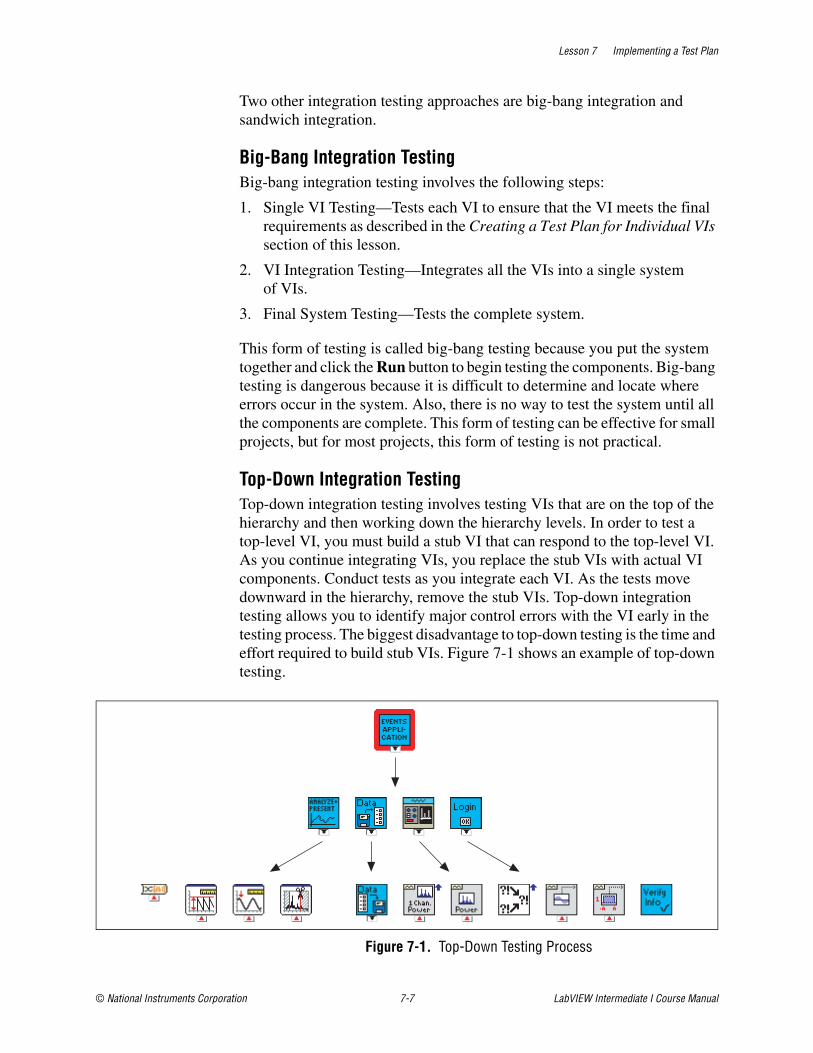
Lesson 7 Implementing a Test Plan
© National Instruments Corporation 7-7 LabVIEW Intermediate I Course Manual
Two other integration testing approaches are big-bang integration and sandwich integration.
Big-Bang Integration TestingBig-bang integration testing involves the following steps:
1. Single VI Testing—Tests each VI to ensure that the VI meets the final requirements as described in the Creating a Test Plan for Individual VIs section of this lesson.
2. VI Integration Testing—Integrates all the VIs into a single system of VIs.
3. Final System Testing—Tests the complete system.
This form of testing is called big-bang testing because you put the system together and click the Run button to begin testing the components. Big-bang testing is dangerous because it is difficult to determine and locate where errors occur in the system. Also, there is no way to test the system until all the components are complete. This form of testing can be effective for small projects, but for most projects, this form of testing is not practical.
Top-Down Integration TestingTop-down integration testing involves testing VIs that are on the top of the hierarchy and then working down the hierarchy levels. In order to test a top-level VI, you must build a stub VI that can respond to the top-level VI. As you continue integrating VIs, you replace the stub VIs with actual VI components. Conduct tests as you integrate each VI. As the tests move downward in the hierarchy, remove the stub VIs. Top-down integration testing allows you to identify major control errors with the VI early in the testing process. The biggest disadvantage to top-down testing is the time and effort required to build stub VIs. Figure 7-1 shows an example of top-down testing.
Figure 7-1. Top-Down Testing Process

Lesson 7 Implementing a Test Plan
LabVIEW Intermediate I Course Manual 7-8 ni.com
Bottom-Up Integration TestingBottom-up integration testing involves integrating and testing the lower-level VIs in the hierarchy and moving up the hierarchy. This form of integration testing requires you to first test the individual VI, then create a driver VI or a control program to coordinate the inputs and outputs of the VI you are integrating. As you continue this process, you can replace the control program with VIs that are higher in the hierarchy. The advantage to bottom-up testing is that you interact with the lowest level components in the system early on in the testing phase. For example, you can test the VI that interacts with the data acquisition device early on to make sure that the device works as required. Another advantage is that as you add a VI to the system, you know if that VI caused an error because you are testing a single VI in the integration of the system. A disadvantage to this integration testing method is that you do not test the top-level control and decision algorithms until the end of testing phase. Figure 7-2 shows an example of bottom-up testing.
Figure 7-2. Bottom-Up Testing Process
Sandwich TestingSandwich testing is a combination of bottom-up and top-down integration testing. This method uses top-down tests to test the upper-level control. Bottom-up tests are used to test the low-level hardware and system functionality. This method takes advantage of the benefits that both integration testing methods use, while minimizing their disadvantages. Figure 7-3 shows an example of sandwich testing.

Lesson 7 Implementing a Test Plan
© National Instruments Corporation 7-9 LabVIEW Intermediate I Course Manual
Figure 7-3. Sandwich Testing Process
Regardless of the approach you take, you must perform regression testing at each step to verify that the previously tested features still work. Regression testing consists of repeating some or all previous tests. If you need to perform the same tests numerous times, consider developing representative subsets of tests to use for frequent regression tests. You can run these subsets of tests at each stage. You can run the more detailed tests to test an individual set of modules if problems arise or as part of a more detailed regression test that periodically occurs during development.
Job AidEach of the integration testing methods except the big-bang method emphasizes that units should be tested before they are integrated. Also, each of the methods encourages you to test with incremental integration and to test the system as components are added. Incremental integration enables you to quickly identify and isolate which VIs generate errors. There is no single incremental testing method that is best for testing a VI. However, incremental integration saves time and helps you create more reliable applications. Use the following checklist to determine if the incremental testing strategy you use is adequate.
❑ The strategy requires you to write fewer stub or driver VIs.
❑ The strategy accurately tests if the VI meets the project requirements.
❑ The strategy enables you to easily determine and locate errors.
❑ The strategy does not introduce errors into the VI.
❑ The strategy is repeatable.
❑ The strategy is specific to the requirement.
Lesson 7 Implementing a Test Plan
LabVIEW Intermediate I Course Manual 7-10 ni.com
Exercise 7-1 Integrate Initialize and Shutdown Functions
GoalLearn techniques to initialize and shutdown a set of code modules.
ScenarioThe Initialize function places the application into a stable mode by initializing all of the modules and clearing the user interface.
When the user selects the File»Exit menu, the application should safely shutdown. Safely shutting down an application requires closing all open memory references.
Design
The Initialize function outlined in the requirements document performs the following actions:
Initialize Error Module
Initialize Display Module
Initialize Cue Module
Initialize File Module
Initialize Hardware Module
Initialize Timing Module
Initialize Stop Timing Module
Disable Front Panel Controls
Initialize Front Panel
Update Cue List
Because you designed the modules to close open memory references, the Shutdown VI accesses the function on the module to shutdown the module. Also, Shutdown needs to send a Stop message to the display loop. Sending a Stop message to the display loop causes that loop to finish executing. The following modules need to shutdown: Display, Hardware, and File. You can re-initialize the Cue module to delete any Cues that are stored in the persistent shift register.
ImplementationThe implementation of the Initialize VI involves calling the modules that you built and wiring the correct data type to them. There is not a specific order that is necessary to call the VIs. Follow the order in the Design section just to be complete.

Lesson 7 Implementing a Test Plan
© National Instruments Corporation 7-11 LabVIEW Intermediate I Course Manual
Initialize1. Create an Integration folder in the Modules project hierarchy.
2. Add tlc_Initialize.vi located in the C:\Exercises\LabVIEW Intermediate I\Course Project\Integration directory to the Integration folder.
3. Open the tlc_Initialize.vi that you just added into the LabVIEW project.
4. Complete the block diagram as shown in Figure 7-4. Use the modules to perform the initialization functions.
5. Create controls for the references by right-clicking the inputs of tlc_Error Module.vi.
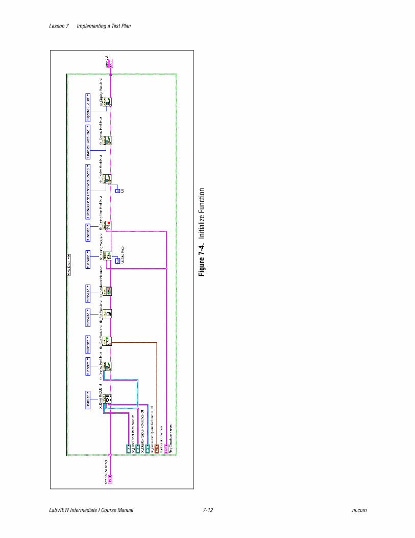
Lesson 7 Implementing a Test Plan
LabVIEW Intermediate I Course Manual 7-12 ni.com
Figu
re 7
-4.
Initi
alize
Fun
ctio
n
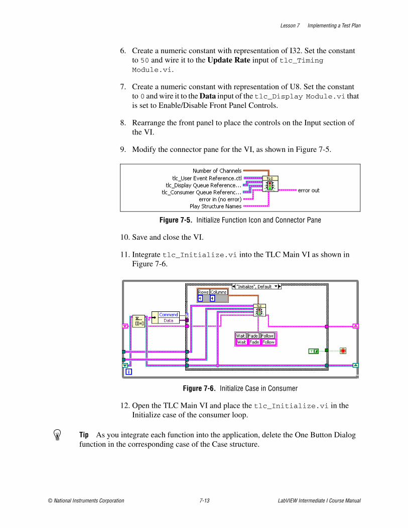
Lesson 7 Implementing a Test Plan
© National Instruments Corporation 7-13 LabVIEW Intermediate I Course Manual
6. Create a numeric constant with representation of I32. Set the constant to 50 and wire it to the Update Rate input of tlc_Timing Module.vi.
7. Create a numeric constant with representation of U8. Set the constant to 0 and wire it to the Data input of the tlc_Display Module.vi that is set to Enable/Disable Front Panel Controls.
8. Rearrange the front panel to place the controls on the Input section of the VI.
9. Modify the connector pane for the VI, as shown in Figure 7-5.
Figure 7-5. Initialize Function Icon and Connector Pane
10. Save and close the VI.
11. Integrate tlc_Initialize.vi into the TLC Main VI as shown in Figure 7-6.
Figure 7-6. Initialize Case in Consumer
12. Open the TLC Main VI and place the tlc_Initialize.vi in the Initialize case of the consumer loop.
Tip As you integrate each function into the application, delete the One Button Dialog function in the corresponding case of the Case structure.
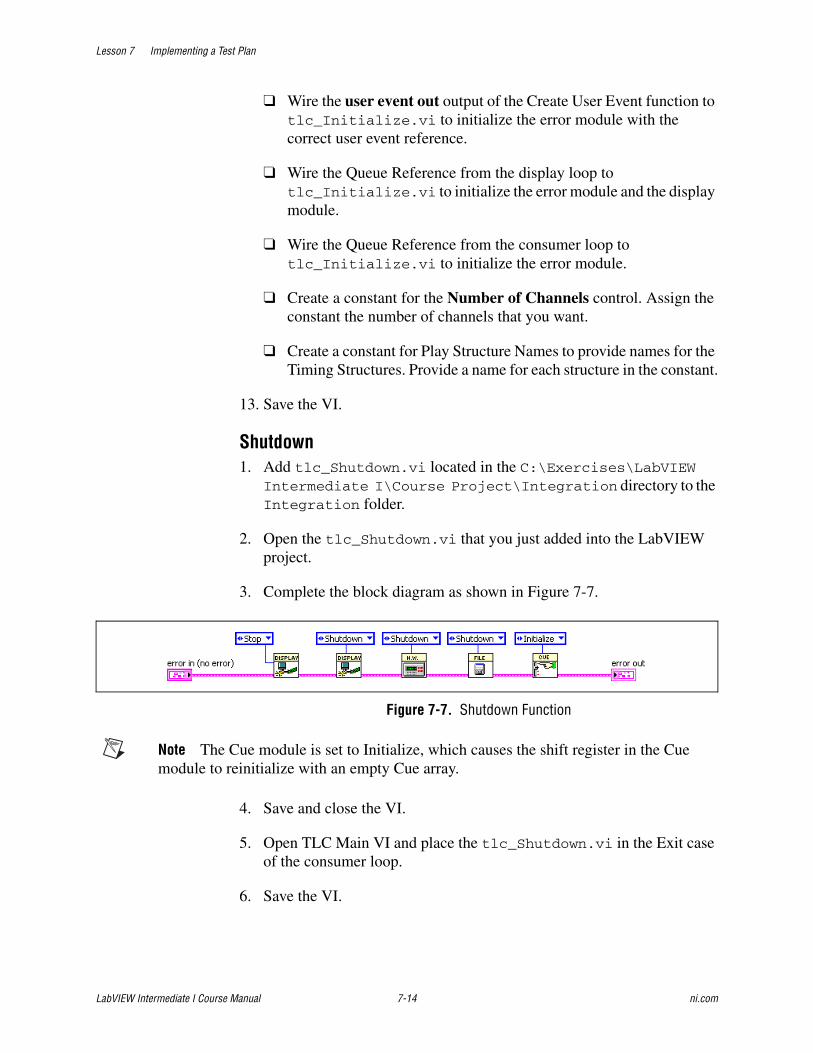
Lesson 7 Implementing a Test Plan
LabVIEW Intermediate I Course Manual 7-14 ni.com
❑ Wire the user event out output of the Create User Event function to tlc_Initialize.vi to initialize the error module with the correct user event reference.
❑ Wire the Queue Reference from the display loop to tlc_Initialize.vi to initialize the error module and the display module.
❑ Wire the Queue Reference from the consumer loop to tlc_Initialize.vi to initialize the error module.
❑ Create a constant for the Number of Channels control. Assign the constant the number of channels that you want.
❑ Create a constant for Play Structure Names to provide names for the Timing Structures. Provide a name for each structure in the constant.
13. Save the VI.
Shutdown1. Add tlc_Shutdown.vi located in the C:\Exercises\LabVIEW
Intermediate I\Course Project\Integration directory to the Integration folder.
2. Open the tlc_Shutdown.vi that you just added into the LabVIEW project.
3. Complete the block diagram as shown in Figure 7-7.
Figure 7-7. Shutdown Function
Note The Cue module is set to Initialize, which causes the shift register in the Cue module to reinitialize with an empty Cue array.
4. Save and close the VI.
5. Open TLC Main VI and place the tlc_Shutdown.vi in the Exit case of the consumer loop.
6. Save the VI.

Lesson 7 Implementing a Test Plan
© National Instruments Corporation 7-15 LabVIEW Intermediate I Course Manual
Testing1. Run the TLC Main VI and select File»Exit. Verify that the Shutdown
function causes the application to end. After you integrate the Display functionality, you also can verify that the Initialize function executes.
End of Exercise 7-1
Lesson 7 Implementing a Test Plan
LabVIEW Intermediate I Course Manual 7-16 ni.com
Exercise 7-2 Integrate Display Module
GoalLearn techniques to update the controls on the front panel.
ScenarioThe design of this application splits the functionality into three separate loops. The producer loop uses an Event structure to monitor changes to the front panel. The consumer loop handles all of the processing for the application. The display loop updates the user interface. The advantage to this three loop architecture is that functionality is contained within individual parallel processes. This increases performance and stability of the application. Using the three loops also improves the maintainability and scalability of the application.
Implement the code in the display loop to update the user interface.
DesignIn order to perform the functions specified in the requirements document, you need to have the following display functions: Initialize Front Panel, Update Front Panel Channels, Select Cue in Cue List, Enable/Disable Front Panel Controls, and Update Cue List. Implement these functions in the display loop of the top-level VI. The advantage to implementing this code on the top-level VI is that you have direct access to the terminals on the front panel.
Implementation1. Open the TLC Main VI.
2. Open the block diagram and edit the display loop.
Modify the following cases in the Case structure.
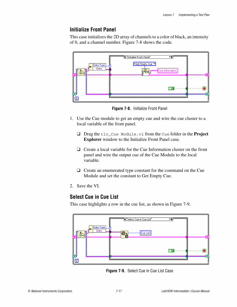
Lesson 7 Implementing a Test Plan
© National Instruments Corporation 7-17 LabVIEW Intermediate I Course Manual
Initialize Front PanelThis case initializes the 2D array of channels to a color of black, an intensity of 0, and a channel number. Figure 7-8 shows the code.
Figure 7-8. Initialize Front Panel
1. Use the Cue module to get an empty cue and wire the cue cluster to a local variable of the front panel.
❑ Drag the tlc_Cue Module.vi from the Cue folder in the Project Explorer window to the Initialize Front Panel case.
❑ Create a local variable for the Cue Information cluster on the front panel and wire the output cue of the Cue Module to the local variable.
❑ Create an enumerated type constant for the command on the Cue Module and set the constant to Get Empty Cue.
2. Save the VI.
Select Cue in Cue ListThis case highlights a row in the cue list, as shown in Figure 7-9.
Figure 7-9. Select Cue in Cue List Case
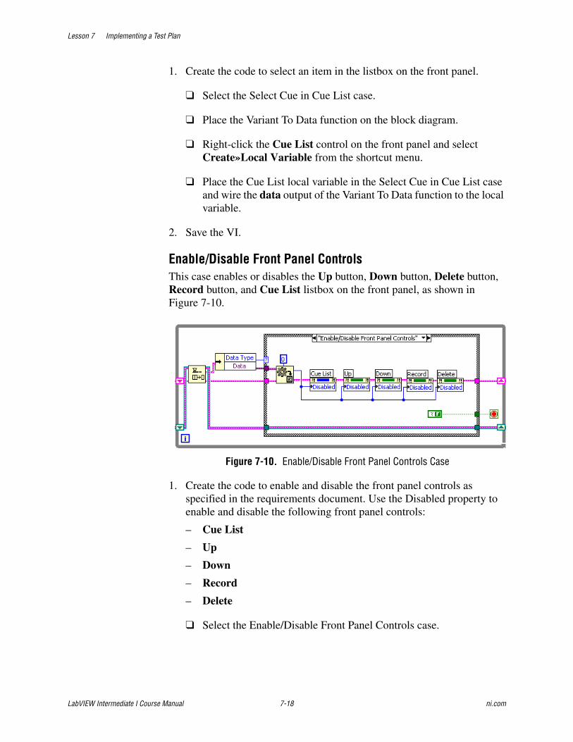
Lesson 7 Implementing a Test Plan
LabVIEW Intermediate I Course Manual 7-18 ni.com
1. Create the code to select an item in the listbox on the front panel.
❑ Select the Select Cue in Cue List case.
❑ Place the Variant To Data function on the block diagram.
❑ Right-click the Cue List control on the front panel and select Create»Local Variable from the shortcut menu.
❑ Place the Cue List local variable in the Select Cue in Cue List case and wire the data output of the Variant To Data function to the local variable.
2. Save the VI.
Enable/Disable Front Panel ControlsThis case enables or disables the Up button, Down button, Delete button, Record button, and Cue List listbox on the front panel, as shown in Figure 7-10.
Figure 7-10. Enable/Disable Front Panel Controls Case
1. Create the code to enable and disable the front panel controls as specified in the requirements document. Use the Disabled property to enable and disable the following front panel controls:
– Cue List
– Up
– Down
– Record
– Delete
❑ Select the Enable/Disable Front Panel Controls case.
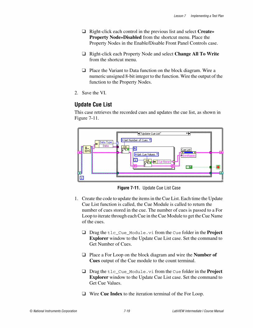
Lesson 7 Implementing a Test Plan
© National Instruments Corporation 7-19 LabVIEW Intermediate I Course Manual
❑ Right-click each control in the previous list and select Create»Property Node»Disabled from the shortcut menu. Place the Property Nodes in the Enable/Disable Front Panel Controls case.
❑ Right-click each Property Node and select Change All To Write from the shortcut menu.
❑ Place the Variant to Data function on the block diagram. Wire a numeric unsigned 8-bit integer to the function. Wire the output of the function to the Property Nodes.
2. Save the VI.
Update Cue ListThis case retrieves the recorded cues and updates the cue list, as shown in Figure 7-11.
Figure 7-11. Update Cue List Case
1. Create the code to update the items in the Cue List. Each time the Update Cue List function is called, the Cue Module is called to return the number of cues stored in the cue. The number of cues is passed to a For Loop to iterate through each Cue in the Cue Module to get the Cue Name of the cues.
❑ Drag the tlc_Cue_Module.vi from the Cue folder in the Project Explorer window to the Update Cue List case. Set the command to Get Number of Cues.
❑ Place a For Loop on the block diagram and wire the Number of Cues output of the Cue module to the count terminal.
❑ Drag the tlc_Cue_Module.vi from the Cue folder in the Project Explorer window to the Update Cue List case. Set the command to Get Cue Values.
❑ Wire Cue Index to the iteration terminal of the For Loop.
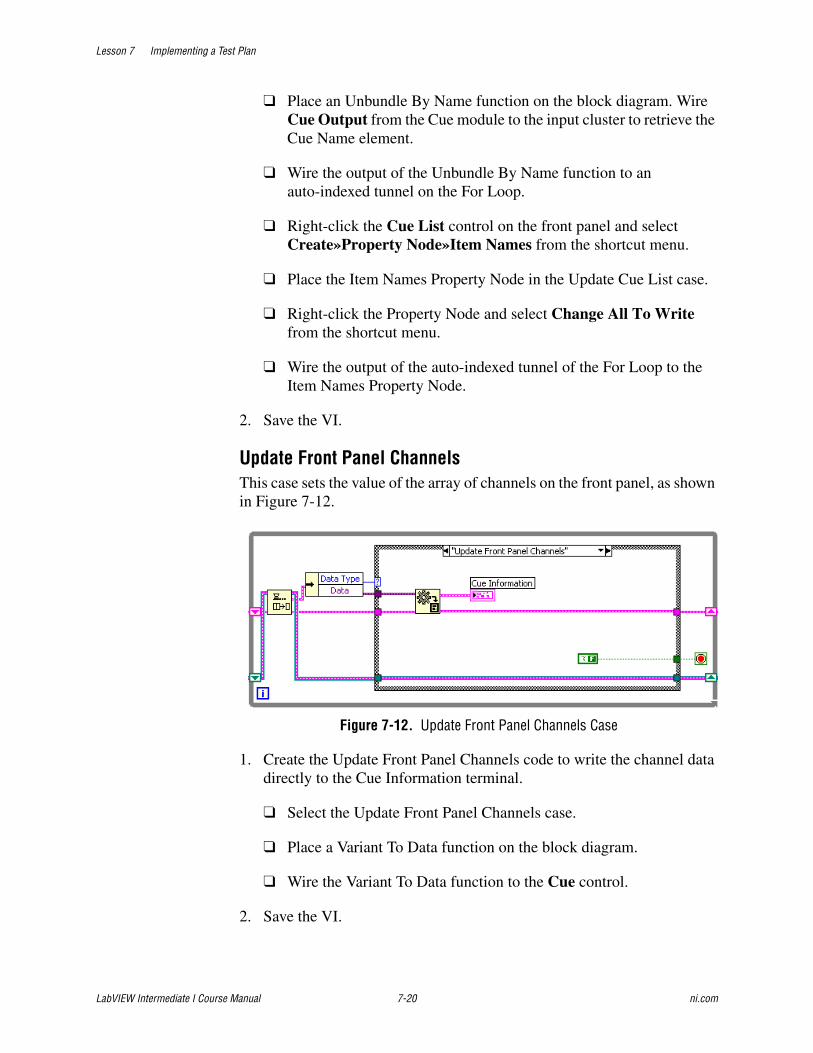
Lesson 7 Implementing a Test Plan
LabVIEW Intermediate I Course Manual 7-20 ni.com
❑ Place an Unbundle By Name function on the block diagram. Wire Cue Output from the Cue module to the input cluster to retrieve the Cue Name element.
❑ Wire the output of the Unbundle By Name function to an auto-indexed tunnel on the For Loop.
❑ Right-click the Cue List control on the front panel and select Create»Property Node»Item Names from the shortcut menu.
❑ Place the Item Names Property Node in the Update Cue List case.
❑ Right-click the Property Node and select Change All To Write from the shortcut menu.
❑ Wire the output of the auto-indexed tunnel of the For Loop to the Item Names Property Node.
2. Save the VI.
Update Front Panel ChannelsThis case sets the value of the array of channels on the front panel, as shown in Figure 7-12.
Figure 7-12. Update Front Panel Channels Case
1. Create the Update Front Panel Channels code to write the channel data directly to the Cue Information terminal.
❑ Select the Update Front Panel Channels case.
❑ Place a Variant To Data function on the block diagram.
❑ Wire the Variant To Data function to the Cue control.
2. Save the VI.
Lesson 7 Implementing a Test Plan
© National Instruments Corporation 7-21 LabVIEW Intermediate I Course Manual
Testing1. Run the VI.
2. The Initialize function is called, which initializes the front panel. All of the channels on the front panel should initialize with the correct channel numbers.
End of Exercise 7-2
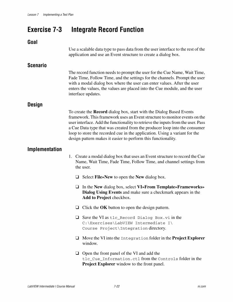
Lesson 7 Implementing a Test Plan
LabVIEW Intermediate I Course Manual 7-22 ni.com
Exercise 7-3 Integrate Record Function
GoalUse a scalable data type to pass data from the user interface to the rest of the application and use an Event structure to create a dialog box.
ScenarioThe record function needs to prompt the user for the Cue Name, Wait Time, Fade Time, Follow Time, and the settings for the channels. Prompt the user with a modal dialog box where the user can enter values. After the user enters the values, the values are placed into the Cue module, and the user interface updates.
DesignTo create the Record dialog box, start with the Dialog Based Events framework. This framework uses an Event structure to monitor events on the user interface. Add the functionality to retrieve the inputs from the user. Pass a Cue Data type that was created from the producer loop into the consumer loop to store the recorded cue in the application. Using a variant for the design pattern makes it easier to perform this functionality.
Implementation1. Create a modal dialog box that uses an Event structure to record the Cue
Name, Wait Time, Fade Time, Follow Time, and channel settings from the user.
❑ Select File»New to open the New dialog box.
❑ In the New dialog box, select VI»From Template»Frameworks»Dialog Using Events and make sure a checkmark appears in the Add to Project checkbox.
❑ Click the OK button to open the design pattern.
❑ Save the VI as tlc_Record Dialog Box.vi in the C:\Exercises\LabVIEW Intermediate I\Course Project\Integration directory.
❑ Move the VI into the Integration folder in the Project Explorer window.
❑ Open the front panel of the VI and add the tlc_Cue_Information.ctl from the Controls folder in the Project Explorer window to the front panel.
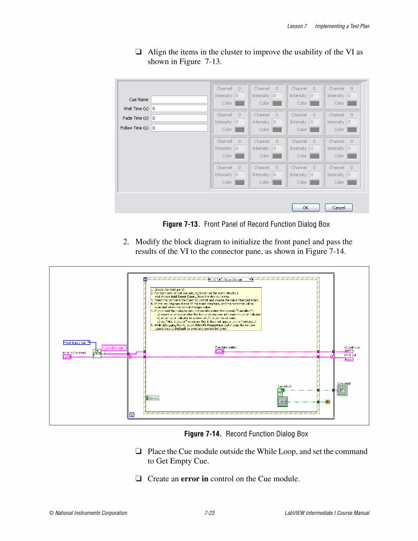
Lesson 7 Implementing a Test Plan
© National Instruments Corporation 7-23 LabVIEW Intermediate I Course Manual
❑ Align the items in the cluster to improve the usability of the VI as shown in Figure 7-13.
Figure 7-13. Front Panel of Record Function Dialog Box
2. Modify the block diagram to initialize the front panel and pass the results of the VI to the connector pane, as shown in Figure 7-14.
Figure 7-14. Record Function Dialog Box
❑ Place the Cue module outside the While Loop, and set the command to Get Empty Cue.
❑ Create an error in control on the Cue module.
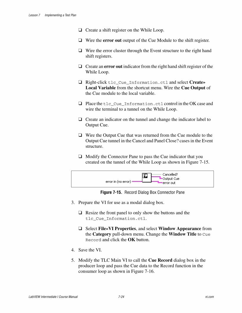
Lesson 7 Implementing a Test Plan
LabVIEW Intermediate I Course Manual 7-24 ni.com
❑ Create a shift register on the While Loop.
❑ Wire the error out output of the Cue Module to the shift register.
❑ Wire the error cluster through the Event structure to the right hand shift registers.
❑ Create an error out indicator from the right hand shift register of the While Loop.
❑ Right-click tlc_Cue_Information.ctl and select Create»Local Variable from the shortcut menu. Wire the Cue Output of the Cue module to the local variable.
❑ Place the tlc_Cue_Information.ctl control in the OK case and wire the terminal to a tunnel on the While Loop.
❑ Create an indicator on the tunnel and change the indicator label to Output Cue.
❑ Wire the Output Cue that was returned from the Cue module to the Output Cue tunnel in the Cancel and Panel Close? cases in the Event structure.
❑ Modify the Connector Pane to pass the Cue indicator that you created on the tunnel of the While Loop as shown in Figure 7-15.
Figure 7-15. Record Dialog Box Connector Pane
3. Prepare the VI for use as a modal dialog box.
❑ Resize the front panel to only show the buttons and the tlc_Cue_Information.ctl.
❑ Select File»VI Properties, and select Window Appearance from the Category pull-down menu. Change the Window Title to Cue Record and click the OK button.
4. Save the VI.
5. Modify the TLC Main VI to call the Cue Record dialog box in the producer loop and pass the Cue data to the Record function in the consumer loop as shown in Figure 7-16.
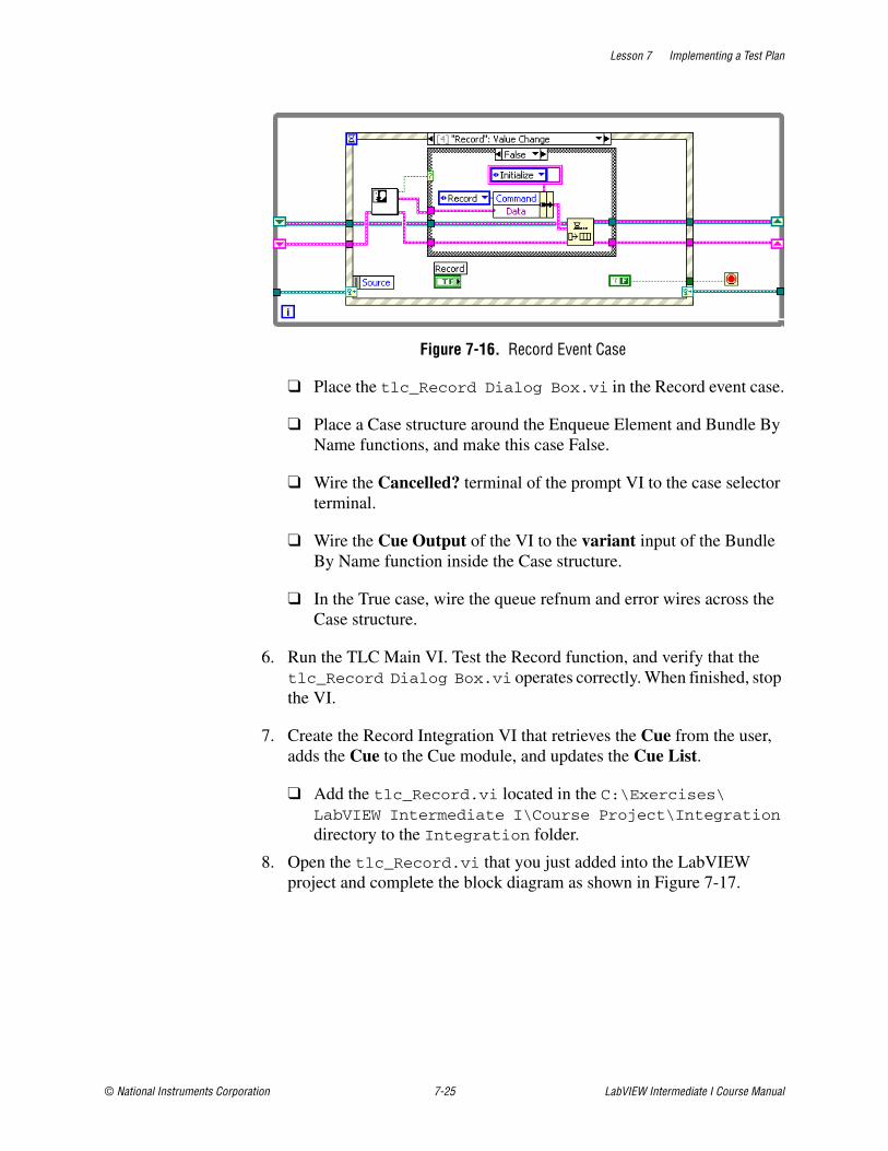
Lesson 7 Implementing a Test Plan
© National Instruments Corporation 7-25 LabVIEW Intermediate I Course Manual
Figure 7-16. Record Event Case
❑ Place the tlc_Record Dialog Box.vi in the Record event case.
❑ Place a Case structure around the Enqueue Element and Bundle By Name functions, and make this case False.
❑ Wire the Cancelled? terminal of the prompt VI to the case selector terminal.
❑ Wire the Cue Output of the VI to the variant input of the Bundle By Name function inside the Case structure.
❑ In the True case, wire the queue refnum and error wires across the Case structure.
6. Run the TLC Main VI. Test the Record function, and verify that the tlc_Record Dialog Box.vi operates correctly. When finished, stop the VI.
7. Create the Record Integration VI that retrieves the Cue from the user, adds the Cue to the Cue module, and updates the Cue List.
❑ Add the tlc_Record.vi located in the C:\Exercises\LabVIEW Intermediate I\Course Project\Integration directory to the Integration folder.
8. Open the tlc_Record.vi that you just added into the LabVIEW project and complete the block diagram as shown in Figure 7-17.

Lesson 7 Implementing a Test Plan
LabVIEW Intermediate I Course Manual 7-26 ni.com
Figure 7-17. Record Function
9. Place two Display Modules and one Cue Module in the No Error case.
10. Wire the Cue data to the Display Module and the Cue Module.
11. Create and set the enums as shown in Figure 7-17.
12. Save and close the VI.
13. Modify the consumer loop to call the Record VI and convert the variant data into data that the Record VI can accept. Figure 7-18 shows the completed Record case in the consumer loop.
Figure 7-18. Record Case in Consumer
❑ Place a Variant To Data function in the consumer loop.
❑ Place tlc_Record.vi on the block diagram and connect the terminals.
14. Save the VI.
Lesson 7 Implementing a Test Plan
© National Instruments Corporation 7-27 LabVIEW Intermediate I Course Manual
Testing1. Run the TLC Main VI.
2. Click the Record button and record a Cue.
3. If the application is running correctly, you should see that the front panel channels update with the Cue you recorded, and the Cue List updates with the name of the cue that you entered in the Record Dialog Box.
4. Stop the VI by selecting File»Exit.
End of Exercise 7-3

Lesson 7 Implementing a Test Plan
LabVIEW Intermediate I Course Manual 7-28 ni.com
Exercise 7-4 Integrate Play Function
GoalLearn a technique to execute a state machine design pattern in a producer/consumer (events) design pattern.
ScenarioThe Play functionality for the Theatre Light Controller is best implemented as a state machine. Figure 7-19 shows the states of the Play function.
Figure 7-19. Play Function Flowchart
Implementing a state machine inside a producer/consumer (events) design pattern requires some insight into how the producer/consumer (events) design pattern operates. As you have seen in previous exercises, the design pattern receives an event in the producer loop, and sends a message to the consumer loop to do some computation on the event. The consumer loop is designed to compute a single message from the producer. Implementing a state machine requires a looping mechanism that is not native to the producer/consumer (events) design pattern. You can imitate a loop with the producer/consumer (events) design pattern by placing a message in the consumer queue. In your application, you want to stay in the Play function to implement the wait, fade, and follow timing requirements for the application. Place messages in the consumer queue to stay in the Play case in the consumer loop until the Play function completes. This method of implementing a state machine inside the producer/consumer (events) design pattern introduces some complexities when you implement the capability to stop a play.
Cue Does Not
Exist
Initialize Load Cue Wait Time
Check forNext Cue Follow Time Fade Time
Cue Exists
Begin Play
Start
End
CueExists
Cue Does Not Exist
Lesson 7 Implementing a Test Plan
© National Instruments Corporation 7-29 LabVIEW Intermediate I Course Manual
DesignThe Play function uses the Timing module to implement the wait, fade, and follow timing requirements. The Timing module performs the majority of the work. Modify the Timing module to perform the fade of the channels by taking advantage of a pre-built VI that takes the desired channel data and increments or decrements the channel intensity. Using a Timed Loop Structure for this operation improves the performance and reliability of the the fade timing requirements.
After you modify the Timing module, integrate the Play function into the TLC Main VI. At this point in the exercise, you see how you can implement a state machine in a producer/consumer design pattern.
ImplementationBuild the play functionality to place in the consumer loop.
1. Open the Timing module and modify the Fade state to call the tlc_Play_Update Cue.vi which calculates all of the channel intensities and colors. The Fade state uses a Timed loop that runs for the number of seconds specified by the Fade Time. Placing the VI that calculates the channel and intensity inside the timed loop creates a reliable channel fade.
❑ Add tlc_Play_Update Cue.vi located in the C:\Exercises\LabVIEW Intermediate I\Course Project\Integration directory to the Integration folder.
❑ Open the tlc_Play_Update Cue.vi and examine how the VI operates.
– Notice that the VI calls the Light Color Controller VI, which calculates a color based on intensity.
– Notice also how the VI sends a message to the Hardware module and Display module.
– Close the VI.
❑ Modify the Fade state of the Timing module to call the tlc_Play_Update Cue.vi as shown in Figure 7-20.
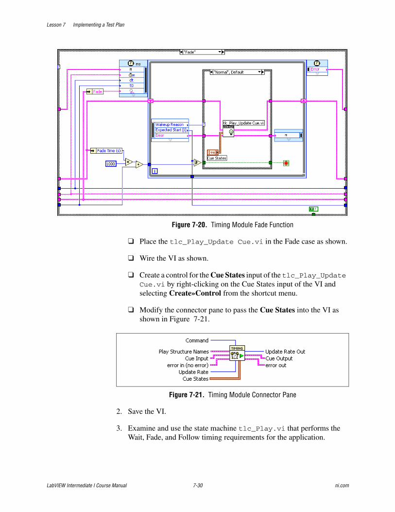
Lesson 7 Implementing a Test Plan
LabVIEW Intermediate I Course Manual 7-30 ni.com
Figure 7-20. Timing Module Fade Function
❑ Place the tlc_Play_Update Cue.vi in the Fade case as shown.
❑ Wire the VI as shown.
❑ Create a control for the Cue States input of the tlc_Play_Update Cue.vi by right-clicking on the Cue States input of the VI and selecting Create»Control from the shortcut menu.
❑ Modify the connector pane to pass the Cue States into the VI as shown in Figure 7-21.
Figure 7-21. Timing Module Connector Pane
2. Save the VI.
3. Examine and use the state machine tlc_Play.vi that performs the Wait, Fade, and Follow timing requirements for the application.
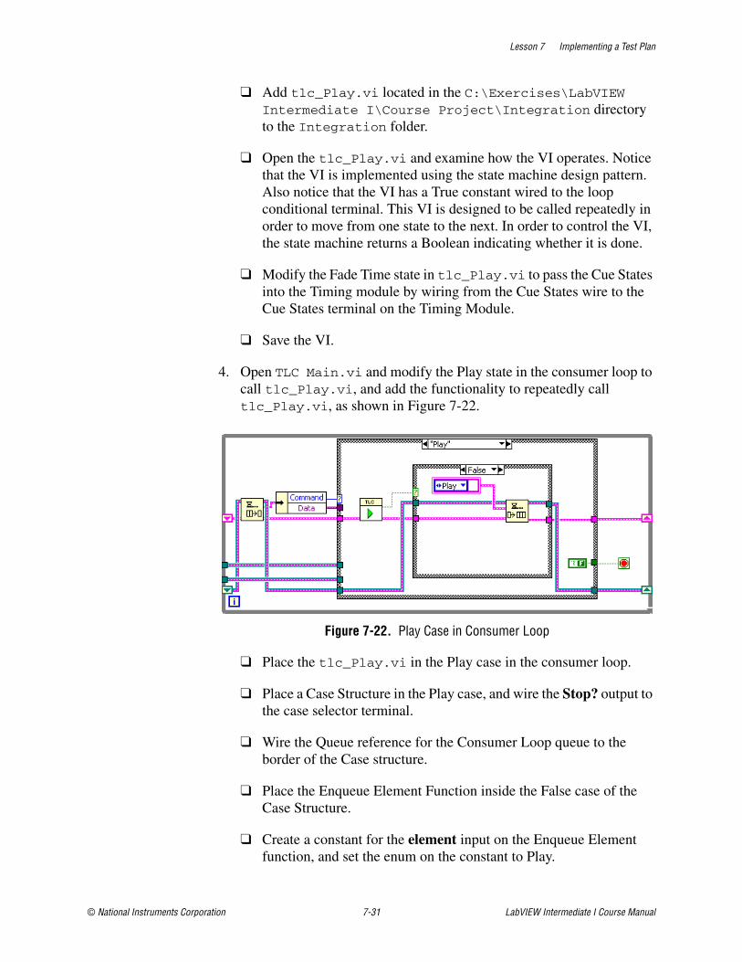
Lesson 7 Implementing a Test Plan
© National Instruments Corporation 7-31 LabVIEW Intermediate I Course Manual
❑ Add tlc_Play.vi located in the C:\Exercises\LabVIEW Intermediate I\Course Project\Integration directory to the Integration folder.
❑ Open the tlc_Play.vi and examine how the VI operates. Notice that the VI is implemented using the state machine design pattern. Also notice that the VI has a True constant wired to the loop conditional terminal. This VI is designed to be called repeatedly in order to move from one state to the next. In order to control the VI, the state machine returns a Boolean indicating whether it is done.
❑ Modify the Fade Time state in tlc_Play.vi to pass the Cue States into the Timing module by wiring from the Cue States wire to the Cue States terminal on the Timing Module.
❑ Save the VI.
4. Open TLC Main.vi and modify the Play state in the consumer loop to call tlc_Play.vi, and add the functionality to repeatedly call tlc_Play.vi, as shown in Figure 7-22.
Figure 7-22. Play Case in Consumer Loop
❑ Place the tlc_Play.vi in the Play case in the consumer loop.
❑ Place a Case Structure in the Play case, and wire the Stop? output to the case selector terminal.
❑ Wire the Queue reference for the Consumer Loop queue to the border of the Case structure.
❑ Place the Enqueue Element Function inside the False case of the Case Structure.
❑ Create a constant for the element input on the Enqueue Element function, and set the enum on the constant to Play.
Lesson 7 Implementing a Test Plan
LabVIEW Intermediate I Course Manual 7-32 ni.com
❑ Wire the error cluster and Queue reference to the tunnels on the True case.
5. Save the VI.
Testing1. At this point, you can run the VI, record a cue, and play the Cue.
2. Run the VI.
3. Record a cue with a single channel that contains a color other than black, and an intensity of 100. Set the Wait time to 0, Fade time to 10, and follow time to 0.
4. Click the Play button on the front panel of the VI.
5. The channel that you recorded should begin to fade from 0% intensity to 100% intensity within 10 seconds.
6. Try recording another cue and notice the response of the system.
7. Stop the VI by selecting File»Exit.
End of Exercise 7-4
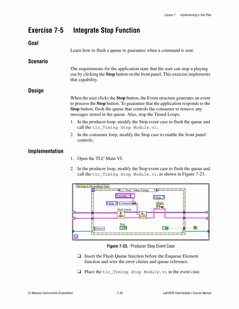
Lesson 7 Implementing a Test Plan
© National Instruments Corporation 7-33 LabVIEW Intermediate I Course Manual
Exercise 7-5 Integrate Stop Function
GoalLearn how to flush a queue to guarantee when a command is sent.
ScenarioThe requirements for the application state that the user can stop a playing cue by clicking the Stop button on the front panel. This exercise implements that capability.
DesignWhen the user clicks the Stop button, the Event structure generates an event to process the Stop button. To guarantee that the application responds to the Stop button, flush the queue that controls the consumer to remove any messages stored in the queue. Also, stop the Timed Loops.
1. In the producer loop, modify the Stop event case to flush the queue and call the tlc_Timing Stop Module.vi.
2. In the consumer loop, modify the Stop case to enable the front panel controls.
Implementation1. Open the TLC Main VI.
2. In the producer loop, modify the Stop event case to flush the queue and call the tlc_Timing Stop Module.vi, as shown in Figure 7-23.
Figure 7-23. Producer Stop Event Case
❑ Insert the Flush Queue function before the Enqueue Element function and wire the error cluster and queue reference.
❑ Place the tlc_Timing Stop Module.vi in the event case.

Lesson 7 Implementing a Test Plan
LabVIEW Intermediate I Course Manual 7-34 ni.com
3. In the consumer loop, modify the Stop case to enable the front panel controls, as shown in Figure 7-24.
Figure 7-24. Consumer Stop Case
❑ Place the Display module in the Stop case, and set the Data Type to Enable/Disable Front Panel Controls. Wire a U8 numeric constant set to 0 to the Data input.
Testing1. Run the TLC Main VI.
2. Record a cue, and play the cue. Verify that the stop functionality works by clicking the Stop button during play.
End of Exercise 7-5
Lesson 7 Implementing a Test Plan
© National Instruments Corporation 7-35 LabVIEW Intermediate I Course Manual
Exercise 7-6 Integrate Error Module
GoalIntegrate an error handling module into the design pattern.
ScenarioThe Error module that you built is designed to safely shutdown the application if an error occurs. Shutting down the producer requires sending a user event to the producer. Shutting down the consumer loop requires placing a Exit message in the queue. Shutting down the display loop requires placing a Stop message in the queue.
When designing and developing an application, it is always important to be mindful of how the application should respond when an error occurs. With the Theatre Light Controller, an error should cause the system to gracefully shut down by executing the cases in each of the application loops that cause the loops to stop.
If an error occurs, the Timed Loops inside the Timing module should also be stopped by calling the tlc_Timing Stop Module.vi.
Design• Modify the TLC Main VI to call the Error module after each
computation in the producer, consumer, and display loop.
Implementation
1. Modify the TLC Main VI to call the Error module after each computation in the producer, consumer, and display loop as shown in Figure 7-25.
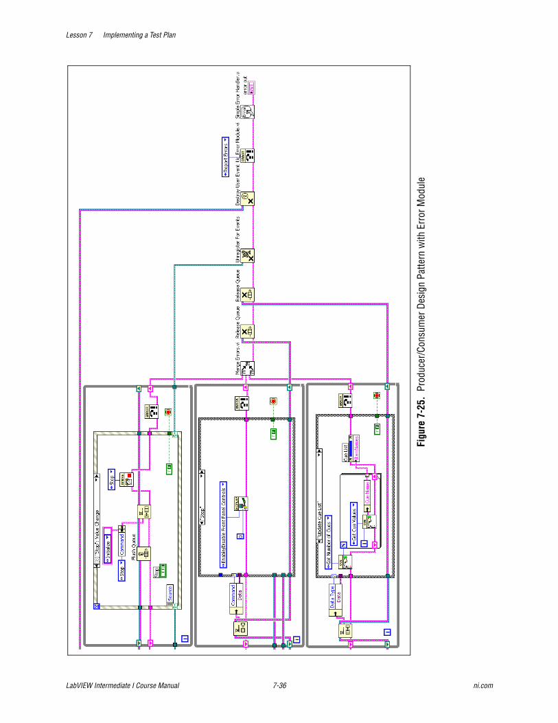
Lesson 7 Implementing a Test Plan
LabVIEW Intermediate I Course Manual 7-36 ni.com
Figu
re 7
-25.
Pro
duce
r/Con
sum
er D
esig
n Pa
ttern
with
Err
or M
odul
e
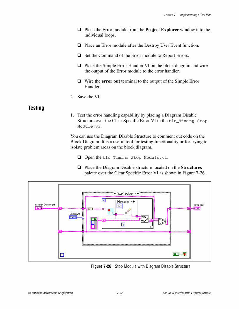
Lesson 7 Implementing a Test Plan
© National Instruments Corporation 7-37 LabVIEW Intermediate I Course Manual
❑ Place the Error module from the Project Explorer window into the individual loops.
❑ Place an Error module after the Destroy User Event function.
❑ Set the Command of the Error module to Report Errors.
❑ Place the Simple Error Handler VI on the block diagram and wire the output of the Error module to the error handler.
❑ Wire the error out terminal to the output of the Simple Error Handler.
2. Save the VI.
Testing1. Test the error handling capability by placing a Diagram Disable
Structure over the Clear Specific Error VI in the tlc_Timing Stop Module.vi.
You can use the Diagram Disable Structure to comment out code on the Block Diagram. It is a useful tool for testing functionality or for trying to isolate problem areas on the block diagram.
❑ Open the tlc_Timing Stop Module.vi.
❑ Place the Diagram Disable structure located on the Structures palette over the Clear Specific Error VI as shown in Figure 7-26.
Figure 7-26. Stop Module with Diagram Disable Structure
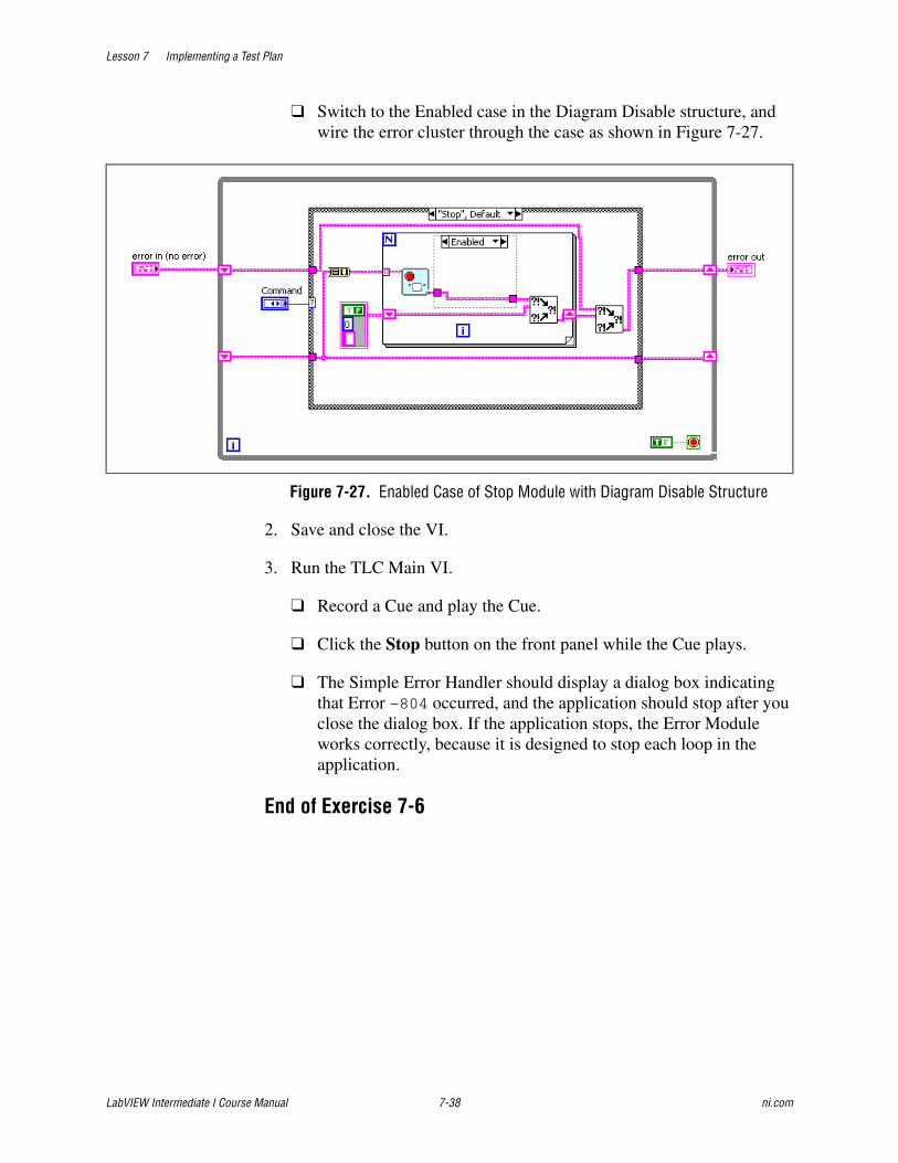
Lesson 7 Implementing a Test Plan
LabVIEW Intermediate I Course Manual 7-38 ni.com
❑ Switch to the Enabled case in the Diagram Disable structure, and wire the error cluster through the case as shown in Figure 7-27.
Figure 7-27. Enabled Case of Stop Module with Diagram Disable Structure
2. Save and close the VI.
3. Run the TLC Main VI.
❑ Record a Cue and play the Cue.
❑ Click the Stop button on the front panel while the Cue plays.
❑ The Simple Error Handler should display a dialog box indicating that Error –804 occurred, and the application should stop after you close the dialog box. If the application stops, the Error Module works correctly, because it is designed to stop each loop in the application.
End of Exercise 7-6
Lesson 7 Implementing a Test Plan
© National Instruments Corporation 7-39 LabVIEW Intermediate I Course Manual
Exercise 7-7 Integrate Save and Load Functions
GoalUse a scalable data type to pass data from the consumer to the producer.
ScenarioThe file save and load functionality are important for the lighting designers who use the software. Most theatres orchestrate a lighting scene during dress rehearsals, and the lighting designer re-uses the lighting design from dress rehearsal for opening night and beyond. Save and load functionality is important for any large scale application.
DesignModify the producer loop in the TLC Main VI to prompt the user for the file name. Several checks need to occur to determine if the user cancels the file operation or tries to open a file that does not exist.
Modify the Save case in the consumer loop to get the values stored in the Cue module and pass the recorded Cues to the File module.
Modify the Load case in the consumer loop to open the file and extract the saved cues, while populating the Cue module with the saved cues.
ImplementationModify the Save case in the consumer loop to get the values stored in the Cue module and pass the recorded Cues to the File module.
Save1. Open TLC Main VI.
2. Modify the Save case in the Menu Selection event of the producer loop, as shown in Figure 7-28.
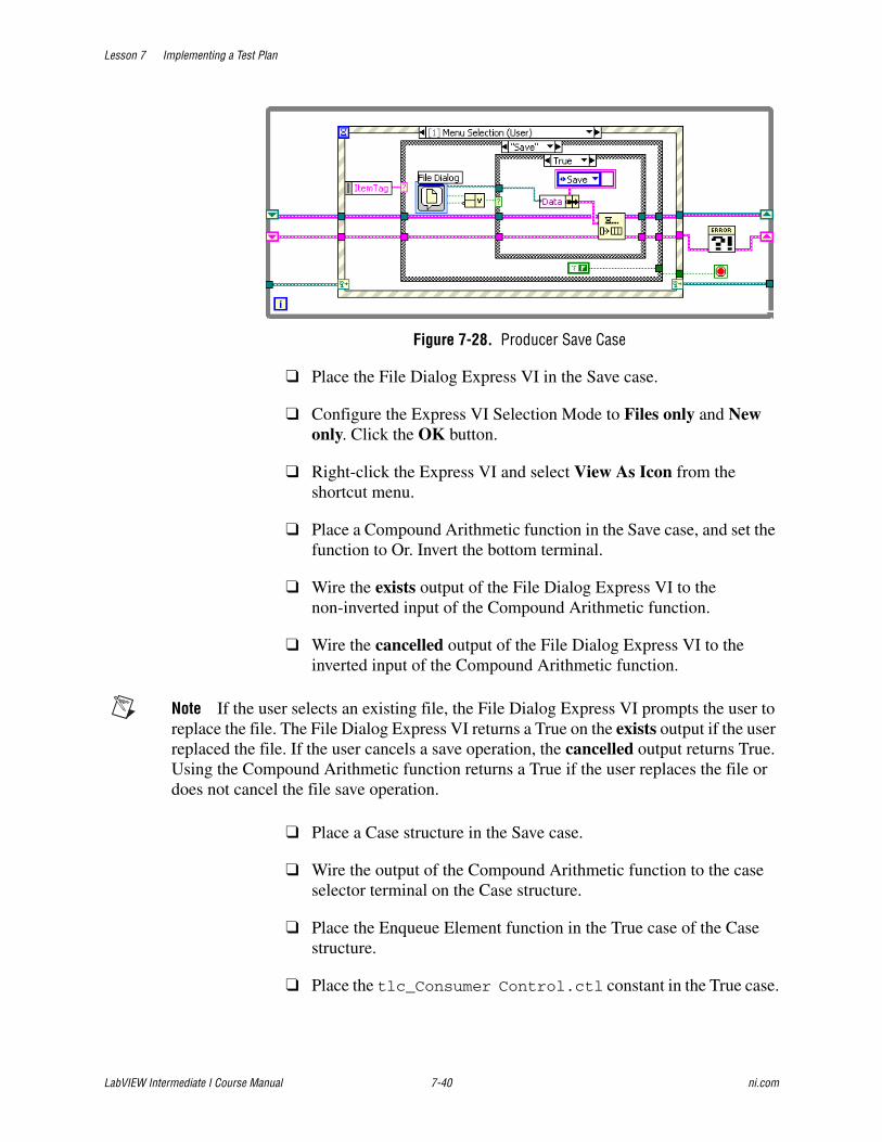
Lesson 7 Implementing a Test Plan
LabVIEW Intermediate I Course Manual 7-40 ni.com
Figure 7-28. Producer Save Case
❑ Place the File Dialog Express VI in the Save case.
❑ Configure the Express VI Selection Mode to Files only and New only. Click the OK button.
❑ Right-click the Express VI and select View As Icon from the shortcut menu.
❑ Place a Compound Arithmetic function in the Save case, and set the function to Or. Invert the bottom terminal.
❑ Wire the exists output of the File Dialog Express VI to the non-inverted input of the Compound Arithmetic function.
❑ Wire the cancelled output of the File Dialog Express VI to the inverted input of the Compound Arithmetic function.
Note If the user selects an existing file, the File Dialog Express VI prompts the user to replace the file. The File Dialog Express VI returns a True on the exists output if the user replaced the file. If the user cancels a save operation, the cancelled output returns True. Using the Compound Arithmetic function returns a True if the user replaces the file or does not cancel the file save operation.
❑ Place a Case structure in the Save case.
❑ Wire the output of the Compound Arithmetic function to the case selector terminal on the Case structure.
❑ Place the Enqueue Element function in the True case of the Case structure.
❑ Place the tlc_Consumer Control.ctl constant in the True case.
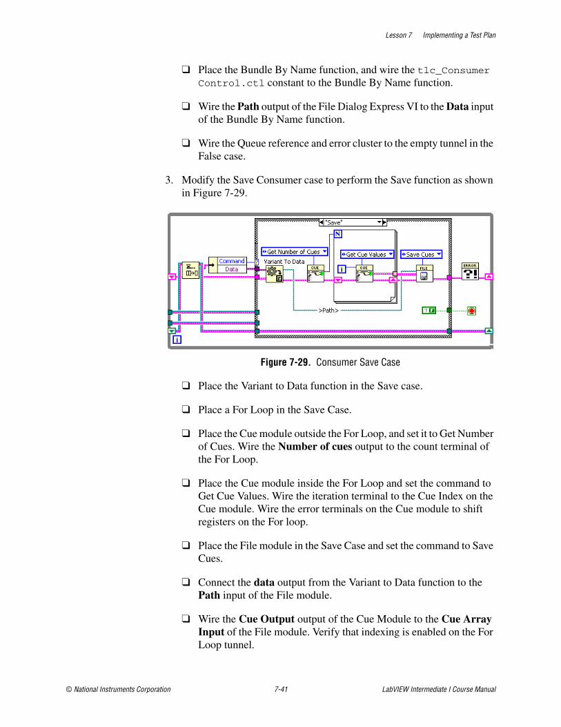
Lesson 7 Implementing a Test Plan
© National Instruments Corporation 7-41 LabVIEW Intermediate I Course Manual
❑ Place the Bundle By Name function, and wire the tlc_Consumer Control.ctl constant to the Bundle By Name function.
❑ Wire the Path output of the File Dialog Express VI to the Data input of the Bundle By Name function.
❑ Wire the Queue reference and error cluster to the empty tunnel in the False case.
3. Modify the Save Consumer case to perform the Save function as shown in Figure 7-29.
Figure 7-29. Consumer Save Case
❑ Place the Variant to Data function in the Save case.
❑ Place a For Loop in the Save Case.
❑ Place the Cue module outside the For Loop, and set it to Get Number of Cues. Wire the Number of cues output to the count terminal of the For Loop.
❑ Place the Cue module inside the For Loop and set the command to Get Cue Values. Wire the iteration terminal to the Cue Index on the Cue module. Wire the error terminals on the Cue module to shift registers on the For loop.
❑ Place the File module in the Save Case and set the command to Save Cues.
❑ Connect the data output from the Variant to Data function to the Path input of the File module.
❑ Wire the Cue Output output of the Cue Module to the Cue Array Input of the File module. Verify that indexing is enabled on the For Loop tunnel.
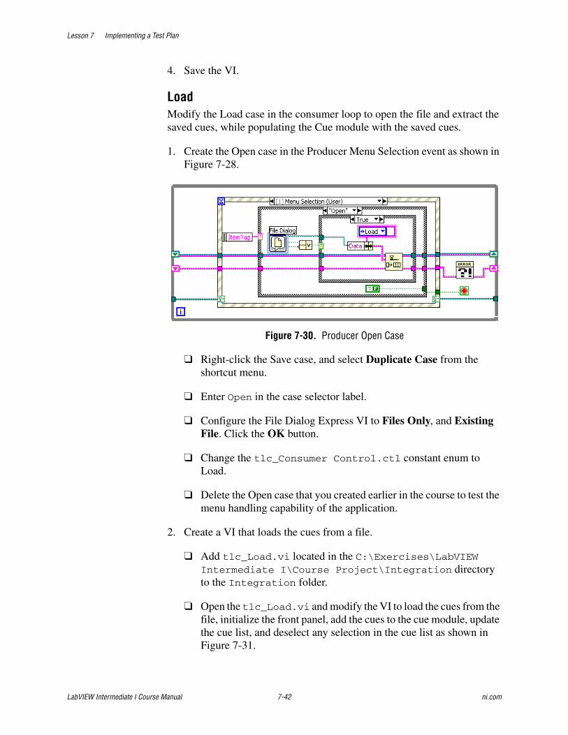
Lesson 7 Implementing a Test Plan
LabVIEW Intermediate I Course Manual 7-42 ni.com
4. Save the VI.
LoadModify the Load case in the consumer loop to open the file and extract the saved cues, while populating the Cue module with the saved cues.
1. Create the Open case in the Producer Menu Selection event as shown in Figure 7-28.
Figure 7-30. Producer Open Case
❑ Right-click the Save case, and select Duplicate Case from the shortcut menu.
❑ Enter Open in the case selector label.
❑ Configure the File Dialog Express VI to Files Only, and Existing File. Click the OK button.
❑ Change the tlc_Consumer Control.ctl constant enum to Load.
❑ Delete the Open case that you created earlier in the course to test the menu handling capability of the application.
2. Create a VI that loads the cues from a file.
❑ Add tlc_Load.vi located in the C:\Exercises\LabVIEW Intermediate I\Course Project\Integration directory to the Integration folder.
❑ Open the tlc_Load.vi and modify the VI to load the cues from the file, initialize the front panel, add the cues to the cue module, update the cue list, and deselect any selection in the cue list as shown in Figure 7-31.
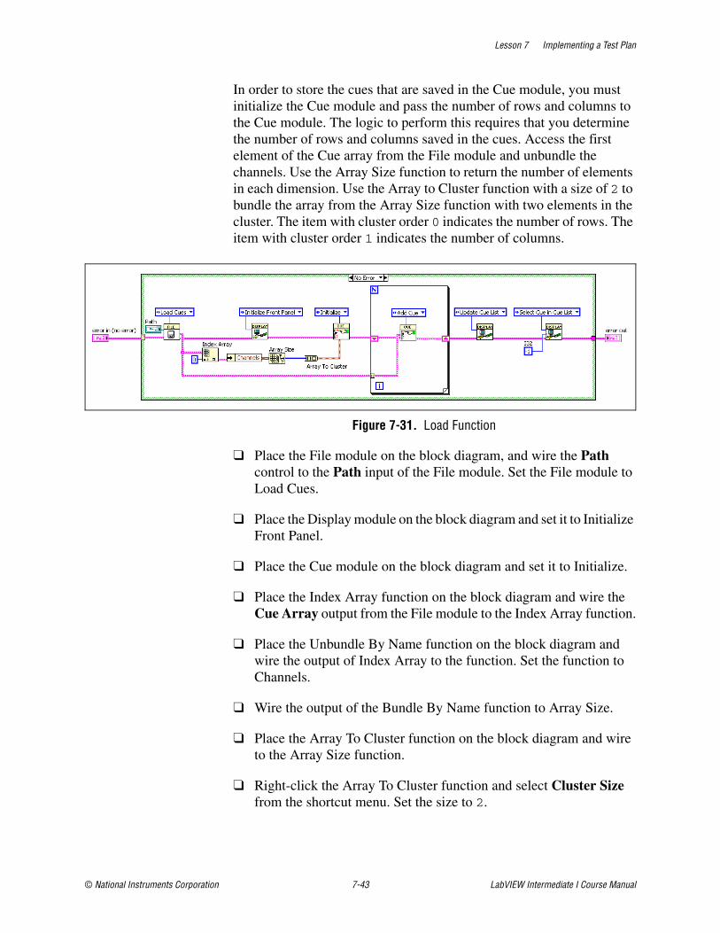
Lesson 7 Implementing a Test Plan
© National Instruments Corporation 7-43 LabVIEW Intermediate I Course Manual
In order to store the cues that are saved in the Cue module, you must initialize the Cue module and pass the number of rows and columns to the Cue module. The logic to perform this requires that you determine the number of rows and columns saved in the cues. Access the first element of the Cue array from the File module and unbundle the channels. Use the Array Size function to return the number of elements in each dimension. Use the Array to Cluster function with a size of 2 to bundle the array from the Array Size function with two elements in the cluster. The item with cluster order 0 indicates the number of rows. The item with cluster order 1 indicates the number of columns.
Figure 7-31. Load Function
❑ Place the File module on the block diagram, and wire the Path control to the Path input of the File module. Set the File module to Load Cues.
❑ Place the Display module on the block diagram and set it to Initialize Front Panel.
❑ Place the Cue module on the block diagram and set it to Initialize.
❑ Place the Index Array function on the block diagram and wire the Cue Array output from the File module to the Index Array function.
❑ Place the Unbundle By Name function on the block diagram and wire the output of Index Array to the function. Set the function to Channels.
❑ Wire the output of the Bundle By Name function to Array Size.
❑ Place the Array To Cluster function on the block diagram and wire to the Array Size function.
❑ Right-click the Array To Cluster function and select Cluster Size from the shortcut menu. Set the size to 2.

Lesson 7 Implementing a Test Plan
LabVIEW Intermediate I Course Manual 7-44 ni.com
❑ Wire the output of Array to Cluster to the Number of Channels input on the Cue module.
❑ Add the functionality to the VI to pass the Cue module with the correct number of rows and columns.
❑ Place a For Loop on the block diagram and wire Cue Array Output from the File module to the border of the For Loop. Verify that indexing is enabled on the tunnel.
❑ Place the Cue module inside the For Loop, set the module to Add Cue, and wire the Cue Array Output from the tunnel to the Input Cue on the Cue module. Connect the error terminals to shift registers on the For loop.
❑ Place the Display module on the block diagram and set it to Update Cue List.
❑ Place another Display module on the block diagram and set it to Select Cue in Cue List. Wire a -1 I32 constant to the Data input of the module.
3. Complete the wiring of the block diagram.
4. Save the VI.
5. Place the tlc_Load.vi in the Load case of the consumer loop in TLC Main VI as shown in Figure 7-32.
Figure 7-32. Load Function
6. Place the Variant to Data function in the Load case and complete the wiring of the case.
7. Save the VI.

Lesson 7 Implementing a Test Plan
© National Instruments Corporation 7-45 LabVIEW Intermediate I Course Manual
Testing1. Run the TLC Main VI.
2. Record several Cues.
3. Select File»Save from the menu.
4. Save the data file as File Test.dat in the C:\Exercises\LabVIEW Intermediate I directory.
5. Stop the VI by selecting File»Exit.
6. Run the TLC Main VI.
7. Load the file you just saved by selecting File»Open and navigating to File Test.dat in the C:\Exercises\LabVIEW Intermediate I directory. Verify that the cues are the ones you saved earlier.
End of Exercise 7-7
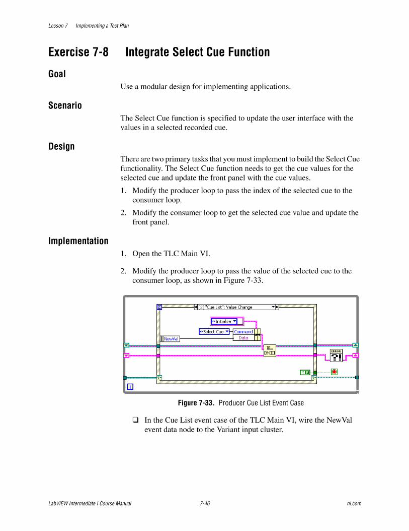
Lesson 7 Implementing a Test Plan
LabVIEW Intermediate I Course Manual 7-46 ni.com
Exercise 7-8 Integrate Select Cue Function
GoalUse a modular design for implementing applications.
ScenarioThe Select Cue function is specified to update the user interface with the values in a selected recorded cue.
DesignThere are two primary tasks that you must implement to build the Select Cue functionality. The Select Cue function needs to get the cue values for the selected cue and update the front panel with the cue values.
1. Modify the producer loop to pass the index of the selected cue to the consumer loop.
2. Modify the consumer loop to get the selected cue value and update the front panel.
Implementation1. Open the TLC Main VI.
2. Modify the producer loop to pass the value of the selected cue to the consumer loop, as shown in Figure 7-33.
Figure 7-33. Producer Cue List Event Case
❑ In the Cue List event case of the TLC Main VI, wire the NewVal event data node to the Variant input cluster.
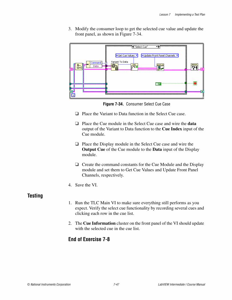
Lesson 7 Implementing a Test Plan
© National Instruments Corporation 7-47 LabVIEW Intermediate I Course Manual
3. Modify the consumer loop to get the selected cue value and update the front panel, as shown in Figure 7-34.
Figure 7-34. Consumer Select Cue Case
❑ Place the Variant to Data function in the Select Cue case.
❑ Place the Cue module in the Select Cue case and wire the data output of the Variant to Data function to the Cue Index input of the Cue module.
❑ Place the Display module in the Select Cue case and wire the Output Cue of the Cue module to the Data input of the Display module.
❑ Create the command constants for the Cue Module and the Display module and set them to Get Cue Values and Update Front Panel Channels, respectively.
4. Save the VI.
Testing1. Run the TLC Main VI to make sure everything still performs as you
expect. Verify the select cue functionality by recording several cues and clicking each row in the cue list.
2. The Cue Information cluster on the front panel of the VI should update with the selected cue in the cue list.
End of Exercise 7-8
Lesson 7 Implementing a Test Plan
LabVIEW Intermediate I Course Manual 7-48 ni.com
Exercise 7-9 Integrate Move Cue Functions
GoalUse a modular design approach to improve the maintainability of an application.
ScenarioThe Move Cue function takes a currently selected cue in the cue list and moves the cue up or down based on which button the user clicks.
DesignFor the Move Cue function, the following set of common elements that occur if the cue moves up or down.
• Swap cues in the cue module.
• Retrieve the value of the selected cue.
• Update the front panel channels.
• Update the cue list.
You can build these common elements for the Move Cue Up and Move Cue Down functions.
Moving a selected cue up requires verification that the selected cue is not the first cue in the cue list. If the selected cue is not the first cue in the cue list, the selected cue is swapped with the previous cue above it. Moving a selected cue down requires a verification that the selected cue is not the last cue in the cue list. If the selected cue is not the last cue in the cue list, the selected cue is swapped with the cue below it.
Implementation1. Add tlc_Move Cue.vi located in the C:\Exercises\LabVIEW
Intermediate I\Course Project\Integration directory to the Integration folder.
❑ Open the tlc_Move Cue.vi that you just added into the LabVIEW project.
❑ Observe the functionality of the VI. Notice how the code that is common to moving the cue up and moving the cue down has been factored out of the VI. Modularizing and simplifying your application in this way improves the readability, scalability, and maintainability of the application.
2. Open the TLC Main VI.
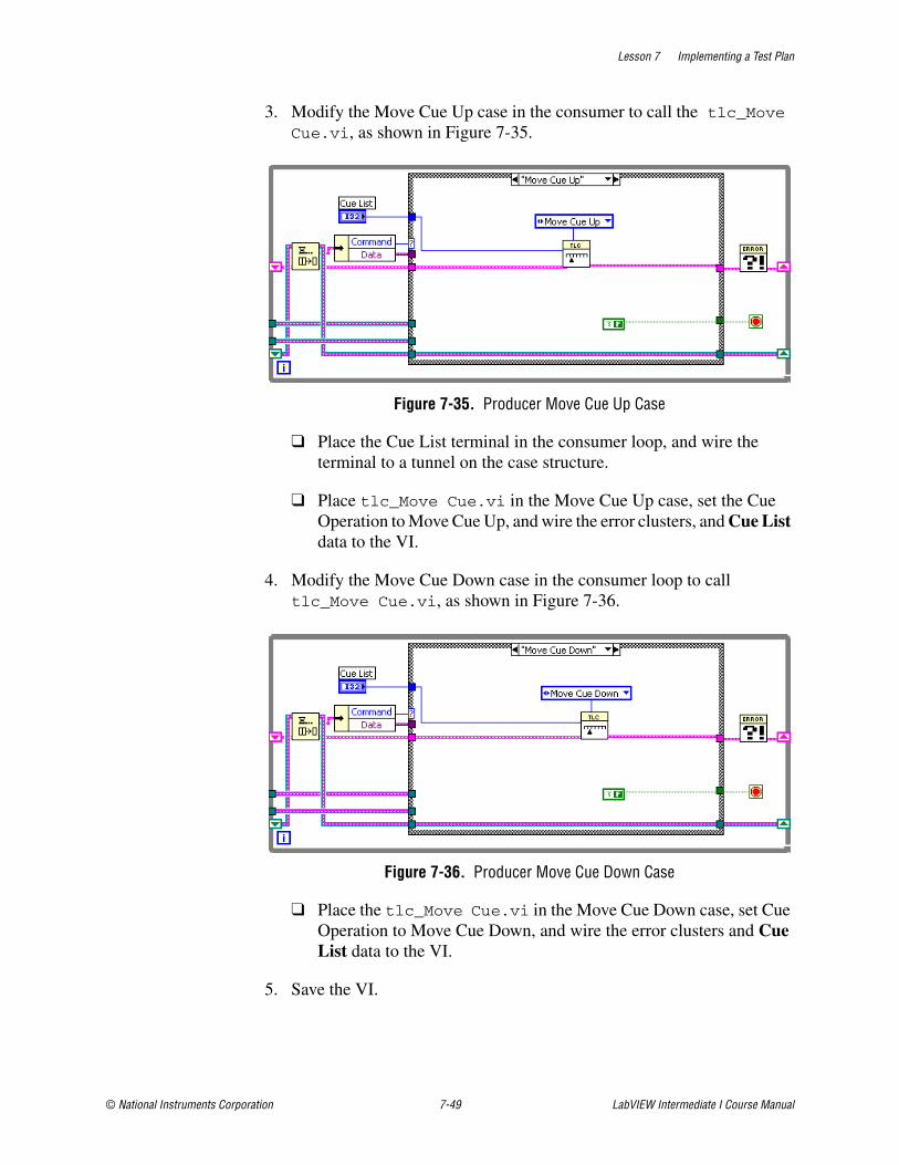
Lesson 7 Implementing a Test Plan
© National Instruments Corporation 7-49 LabVIEW Intermediate I Course Manual
3. Modify the Move Cue Up case in the consumer to call the tlc_Move Cue.vi, as shown in Figure 7-35.
Figure 7-35. Producer Move Cue Up Case
❑ Place the Cue List terminal in the consumer loop, and wire the terminal to a tunnel on the case structure.
❑ Place tlc_Move Cue.vi in the Move Cue Up case, set the Cue Operation to Move Cue Up, and wire the error clusters, and Cue List data to the VI.
4. Modify the Move Cue Down case in the consumer loop to call tlc_Move Cue.vi, as shown in Figure 7-36.
Figure 7-36. Producer Move Cue Down Case
❑ Place the tlc_Move Cue.vi in the Move Cue Down case, set Cue Operation to Move Cue Down, and wire the error clusters and Cue List data to the VI.
5. Save the VI.
Lesson 7 Implementing a Test Plan
LabVIEW Intermediate I Course Manual 7-50 ni.com
Testing1. Run the TLC Main VI.
2. Load the File Test.dat that you created in the C:\Exercises\LabVIEW Intermediate I directory by selecting File»Open.
3. Select a cue in the Cue List and click the Up or Down button. Observe that the cue moves up or down according to the button you click.
Challenge1. Modify the tlc_Move Cue.vi to cause the selected row to move up or
down when the user clicks the Up button or Down button.
End of Exercise 7-9
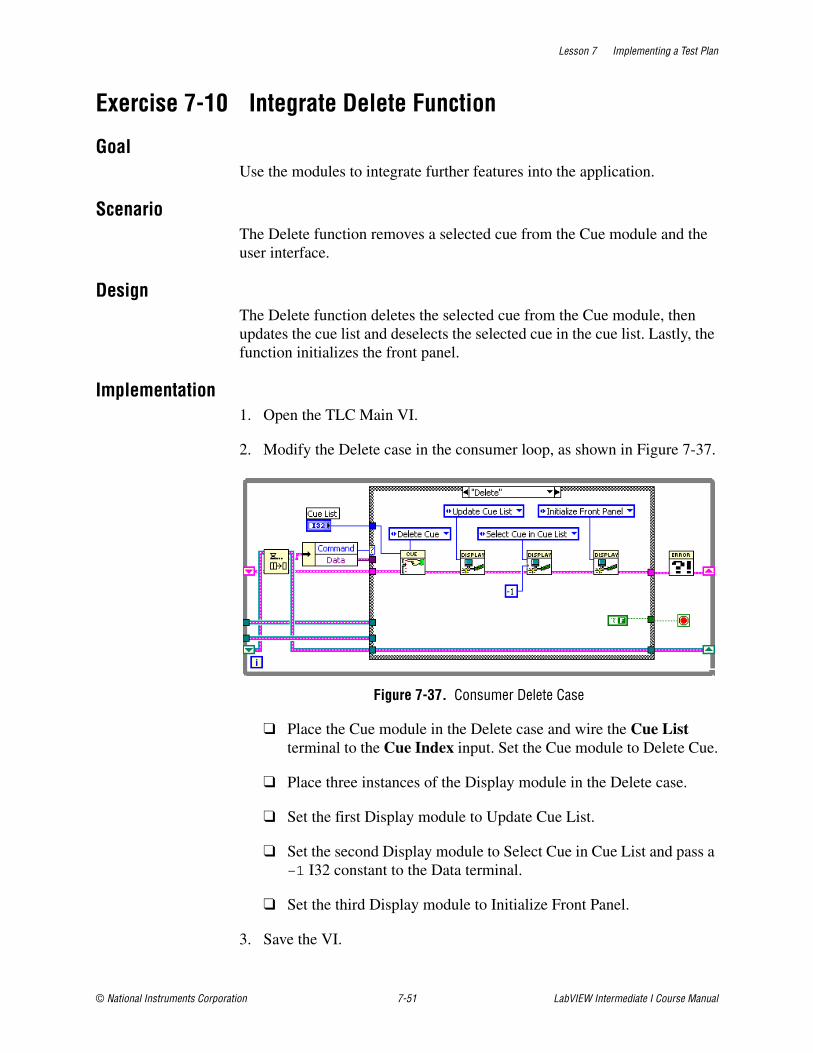
Lesson 7 Implementing a Test Plan
© National Instruments Corporation 7-51 LabVIEW Intermediate I Course Manual
Exercise 7-10 Integrate Delete Function
GoalUse the modules to integrate further features into the application.
ScenarioThe Delete function removes a selected cue from the Cue module and the user interface.
DesignThe Delete function deletes the selected cue from the Cue module, then updates the cue list and deselects the selected cue in the cue list. Lastly, the function initializes the front panel.
Implementation1. Open the TLC Main VI.
2. Modify the Delete case in the consumer loop, as shown in Figure 7-37.
Figure 7-37. Consumer Delete Case
❑ Place the Cue module in the Delete case and wire the Cue List terminal to the Cue Index input. Set the Cue module to Delete Cue.
❑ Place three instances of the Display module in the Delete case.
❑ Set the first Display module to Update Cue List.
❑ Set the second Display module to Select Cue in Cue List and pass a –1 I32 constant to the Data terminal.
❑ Set the third Display module to Initialize Front Panel.
3. Save the VI.
Lesson 7 Implementing a Test Plan
LabVIEW Intermediate I Course Manual 7-52 ni.com
Testing1. Run the TLC Main VI.
2. Load the File Test.dat that you created in the C:\Exercises\LabVIEW Intermediate I directory by selecting File»Open.
3. Highlight a cue in the Cue List and click the Delete button. The cue should be removed from the Cue List.
End of Exercise 7-10
Lesson 7 Implementing a Test Plan
© National Instruments Corporation 7-53 LabVIEW Intermediate I Course Manual
D. Implementing a Test Plan for the SystemSystem testing happens after integration to determine if the product meets customer expectations and to make sure the software works as expected within the hardware system. You can test the system using a set of black box tests to verify that you have met the requirements. With system testing, you test the software to make sure it fits into the overall system as expected. Most LabVIEW applications perform some kind of I/O and also communicate with other applications. Make sure you test how the application communicates with other applications.
When testing the system, consider the following questions:
• Are performance requirements met?
• If my application communicates with another application, does it deal with an unexpected failure of that application well?
Implementing System TestingSystem testing is necessary to ensure that the customer receives the VI they expect. System testing also helps you move the project toward a final sign off on the VI. System tests focus on the following areas:
• Configuration
• Performance
• Stress/load
• Functionality
• Reliability
• Usability
Note Every individual or company has its own method for testing a system. The guidelines described in this section are suggestions for system testing, not requirements. Do not change your existing testing strategy unless it is deficient.
Configuration TestsUse configuration tests to test variations in system and software configurations. Include testing on multiple operating systems unless the requirements document clearly specifies the operating system for the VI. Configuration testing also includes running the VI on different screen resolutions. Make sure the VI can display the required information on the minimum screen resolution stated in the requirements document. Also, test the VI on higher screen resolutions to ensure that the user interface items remain proportional and are not distorted.
Lesson 7 Implementing a Test Plan
LabVIEW Intermediate I Course Manual 7-54 ni.com
Performance TestsPerformance tests define and verify performance benchmarks on the features that exist in the VI. Performance tests include tests for execution time, memory usage, and file sizes. The requirements document should indicate any performance requirements for the VI. Make sure you test each performance requirement in the requirements document.
The final implementation of the system must be able to meet the performance requirements. The system should respond to the user within the predefined limits specified in the requirements. Performance testing also tests how well the software performs with external hardware and interfaces. Check all interfaces outside the system to make sure the software responds within set limits. You can use benchmarking in performance tests to evaluate the performance of the system.
Stress/Load TestsThe stress/load tests define ways to push a VI beyond the required limits in the specification. Typical stress/load tests include large quantities of data, extended time testing, and running a large number of applications concurrently with the VI. Stress/load testing helps guarantee that a VI performs as required when it is deployed.
Functional TestsThe final implementation of a system must be functional to the level stated in the requirements document. The easiest way to test for functionality is to refer to the original requirements document. Check that there is a functional implementation of each requirement listed in the requirements document. Functional testing also must involve the customer at some point to guarantee that the software functions at the level stated in the requirements. After you complete functional testing and the software passes the software test, you can verify the software as functional.
Reliability TestsTesting the reliability of the system often involves using pilot testing to test the system in a non-development environment. There are two forms of pilot testing—alpha and beta testing. Schedule alpha testing to begin when the software first reaches a stage where it can run as a system. Alpha testing typically involves a developer running the system on another computer. Beta testing begins when most of the system is operational and implemented and ready for user feedback. Pilot testing provides a good indication of how reliable the software is when it is deployed on computers other than the development computer. Pilot testing helps identify issues with hardware and operating system compatibility.
Lesson 7 Implementing a Test Plan
© National Instruments Corporation 7-55 LabVIEW Intermediate I Course Manual
You can complete this testing with alpha and beta testing. Alpha and beta testing serve to catch test cases that developers did not consider or complete. With alpha testing, test a functionally complete product in-house to see if any problems arise. With beta testing, when alpha testing is complete, the customers in the field test the product.
Alpha and beta testing are the only testing mechanisms for some companies. Unfortunately, alpha and beta testing actually can be inexact and are not a substitute for other forms of testing that rigorously test each component to verify that the component meets stated objectives. When this type of testing is done late in the development process, it is difficult and costly to incorporate changes suggested as a result.
Alpha TestsThe main focus of alpha testing is to execute system tests, fix errors, and produce beta-quality software. Beta-quality software is defined as software ready for external customer use.
System tests should verify behavior from a user-interaction perspective. Usually a developer does not test his or her own features. Execute system tests and any relevant regression tests from previous releases. You also may want to test existing features that have not been modified but that are affected by new functionality.
Alpha testing usually involves making the software available to other internal departments for testing, including departments whose products interact with or depend on the software.
Beta TestsBeta testing involves sending a beta version of the software to a select list of customers for testing. Include a test plan that asks the users to test certain aspects of the software.
Write additional systems tests to execute during the beta phase. Include performance and usability tests. The tests executed during the alpha phase should be executed again as part of beta testing. Also include time to test the product by freely developing applications like users do. Consider that you might need to create more test cases or update existing tests.
UsabilityUsability measures the potential of a system to accomplish the goals of the user. Some factors that determine system usability are ease-of-use, visual consistency, and a clear, defined process for evolution.
Systems that are usable enable users to concentrate on their tasks and do real work rather than focusing on the tools they use to perform tasks.
Lesson 7 Implementing a Test Plan
LabVIEW Intermediate I Course Manual 7-56 ni.com
Usable VIs have the following characteristics:
• Easy to learn
• Efficient to use
• Provide quick recovery from errors
• Easy to remember
• Enjoyable to use
• Visually pleasing
Usability applies to every aspect of a VI with which a user interacts, including hardware, software, menus, icons, messages, documentation, and training. Every design and development decision made throughout the VI lifecycle has an effect on usability. As users depend more and more on software to get their jobs done and become more critical consumers of software, usability can be a critical factor that ensures that VIs are used.
Usability HeuristicsUse the following usability heuristics1 when evaluating the usability of software. Not meeting one or more of these guidelines may result in a usability issue.
• Visibility of system status—The system should always keep users informed about what is going on, through appropriate feedback within a reasonable time.
• Match between system and the real world—The system should speak the users’ language, with words, phrases, and concepts familiar to the user, rather than system-oriented terms. Follow real-world conventions, making information appear in a natural and logical order.
• User control and freedom—Users often choose system functions by mistake and need a clearly marked “emergency exit” to leave the unwanted state without having to go through an extended dialogue. Support undo and redo.
• Consistency and standards—Users should not have to wonder whether different words, situations, or actions mean the same thing. Follow platform conventions.
• Error prevention—Even better than good error messages is a careful design which prevents a problem from occurring in the first place.
• Recognition rather than recall—Make objects, actions, and options visible. The user should not have to remember information from one part of the dialog to another. Instructions for use of the system should be visible or easily retrievable whenever appropriate.
1. Heuristics for User Interface Design, Jakob Nielsen, http://www.useit.com/papers/heuristic/heuristic_list.html.
Lesson 7 Implementing a Test Plan
© National Instruments Corporation 7-57 LabVIEW Intermediate I Course Manual
• Flexibility and efficiency of use—Accelerators, unseen by the novice user, may often speed up the interaction for the expert user such that the system can cater to both inexperienced and experienced users. Allow users to tailor frequent actions.
• Aesthetic and minimalist design—Dialogs should not contain information which is irrelevant or rarely needed. Every extra unit of information in a dialog competes with the relevant units of information and diminishes their relative visibility.
• Helps users recognize, diagnose, and recover from errors—Error messages should be expressed in plain language (no codes), precisely indicate the problem, and constructively suggest a solution.
• Help and documentation—Even though its better if the system can be used without documentation, it may be necessary to provide help and documentation. Any such information should be easy to search, focused on the user’s task, list concrete steps to be carried out, and not be too large.
Usability TestingUsability testing is a cyclic process, resulting in several iterations of design and test. A typical usability study includes three iterations and a final meeting. Each iteration includes three steps—meeting, testing, and report.
• Meeting—Gather information, consider the different issues encountered, and determine guidelines. Set goals and purposes during this step.
• Testing—Test, analyze, or evaluate the product. Depending on the iteration of usability testing, conduct a usability evaluation, cognitive walkthrough, or formal study of the software.
• Report—Present the test results. Issues are typically listed by priority. Reports increase in detail and complexity with each stage.
Usability Engineering TechniquesUsability engineering involves a variety of techniques that can provide important information about how customers work with your application. Different techniques are used at different stages of development.
For example, as you develop requirements and processes, observations and interviews might be appropriate techniques. Later in the development cycle, as you develop the look and feel of the product, benchmarking, prototyping, and participatory design might be useful techniques. Once you have completed the design, usability testing can be used more effectively. You can even test a paper prototype for usability before you write any code.
Lesson 7 Implementing a Test Plan
LabVIEW Intermediate I Course Manual 7-58 ni.com
There are many techniques you can apply to the usability process. No single technique can ensure the usability of a product. Usability is an iterative process that works best when it occurs in partnership with software development.
Consider incorporating the following usability techniques into the development and testing process:
• User and Task Observations—Observing users at their jobs, identifying their typical work tasks and procedures, analyzing their work processes, and understanding people in the context of their work.
• Interviews, Focus Groups, and Questionnaires—Meeting with users, finding out about their preferences, experiences, and needs.
• Benchmarking and Competitive Analysis—Evaluating the usability of similar products in the marketplace.
• Paper Prototyping—Including users early in the development process, before coding begins, through prototypes prepared on paper.
• Creation of Guidelines—Helping to assure consistency in design through development of standards and guidelines.
• Heuristic Evaluations—Evaluating software against accepted usability principles and making recommendations to enhance usability.
• Usability Testing—Observing users performing real tasks with the application, recording what they do, analyzing the results, and recommending appropriate changes.
Usability engineering provides important benefits in terms of cost, product quality, and customer satisfaction. It can improve development productivity through more efficient design and fewer code revisions. It can help eliminate over-design by emphasizing the functionality required to meet the needs of real users. Design problems can be detected earlier in the development process, saving time and money. It can provide further cost savings through reduced support costs, reduced training requirements, and greater user productivity.
Lesson 7 Implementing a Test Plan
© National Instruments Corporation 7-59 LabVIEW Intermediate I Course Manual
Exercise 7-11 Stress and Load Testing
GoalPerform stress and load testing on the application.
ScenarioBefore releasing an application, a set of system level tests must take place. These tests can consist of usability testing, performance testing, stress, and load testing.
DesignCreate a large set of cues stored in a file that contain random wait times, fade times, follow times, and channel colors and intensities. The VI used to create the large set of cues requests from the user the maximum times to use for the wait, fade, and follow so that it is easier to analyze the functionality of the application.
Implementation1. Open the System Testing Driver.vi located in the
C:\Exercises\LabVIEW Intermediate I\Course Project\System Testing folder.
2. Open the block diagram and examine how this VI uses the modules that you created to create a large set of Cues.
3. Switch to the front panel, and set the following front panel controls:
• Number of Cues = 2000
• Wait Time = 0
• Fade Time = 5
• Follow Time = 0
4. Run the VI.
5. When prompted, save the file as Stress Load Test.dat in the C:\Exercises\LabVIEW Intermediate I\Course Project\System Testing folder.
6. Run the TLC Main VI.
7. Select File»Open to load the file Stress Load Test.dat located in the C:\Exercises\LabVIEW Intermediate I\Course Project\System Testing folder.
Lesson 7 Implementing a Test Plan
LabVIEW Intermediate I Course Manual 7-60 ni.com
8. Click the Play button.
9. Open the Windows Task Manager and monitor the memory usage and performance of the Theatre Light Controller. The large number of cues can indicate if there is a memory or performance issue with the application.
End of Exercise 7-11
Lesson 7 Implementing a Test Plan
© National Instruments Corporation 7-61 LabVIEW Intermediate I Course Manual
Summary• Use code reviews to verify that code is correct.
• Design a test plan for a VI that uses functional and error tests.
• Design an integration test plan that uses top-down, bottom-up, big-bang, or sandwich testing.
• Use integration testing to test the individual VIs as you integrate them into a larger system.
• Perform regression testing at each step of integration to verify that previously tested features still work.
• System tests focus on the following areas.
– Configuration
– Performance
– Stress/load
– Functionality
– Reliability
– Usability
• Develop configuration tests for variations in system and software configuration
• Develop performance tests for VI performance
• Develop stress/load tests that push a VI beyond the required limits
• Functional tests verify that there is a functional implementation of each requirement in the requirements document.
• Design a system test that uses alpha and beta tests for reliability.
• Usability measures the system’s potential to accomplish the goals of the user.

Lesson 7 Implementing a Test Plan
LabVIEW Intermediate I Course Manual 7-62 ni.com
Notes
© National Instruments Corporation 8-1 LabVIEW Intermediate I Course Manual
8Evaluating VI Performance
“Make it Right, Then Make It Fast” — Anonymous
As you develop, you might want to focus on the performance of a VI while you create the VI. However, during development, it is more effective for you to focus on using good design principles to create a VI that works correctly. Wait to identify and improve performance issues after you have a stable, working application. Consider that the rapid rate of improvement in computer technology can compensate for some performance issues. This lesson describes methods to evaluate and improve VI performance.
TopicsA. Steps to Improving PerformanceB. Using VI Metrics to Identify VI Issues
C. Further Identifying VI Issues with VI Analyzer (Optional)
D. Identifying Performance Problems
E. Fixing Performance Problems
Lesson 8 Evaluating VI Performance
LabVIEW Intermediate I Course Manual 8-2 ni.com
A. Steps to Improving PerformanceComputer technology is changing at an exponential rate. In 1965, Gordon Moore, the author of Moore’s Law, observed that the number of transistors per integrated circuit would double every couple of years1. This pace has been consistent over time, and the increase in processing power has followed the rate of miniaturization of integrated circuits. Because of these advances in technology, the price of computer equipment continues to fall, while processing power continues to rise. However, the effort required to develop software that runs on the integrated circuit continues to be challenging and time consuming. In fact, the cost of the developer far exceeds the cost of the computer that runs the program. Therefore, it makes sense to focus your development time on writing correct, well-designed code.
Developing VIs that are scalable, readable, and maintainable helps you create VIs that are correct, thus saving costs over time. However, there are times when VIs are too slow, and purchasing a newer computer to run the VI might not be an option. In this case, there are techniques you can use to identify areas of the code that are causing performance problems. Minimize the time you spend identifying and correcting performance problems because processor technology advances so rapidly that by the time you fix performance problems, a faster computer may be available that compensates for slow VI performance.
To improve performance, identify the location in the VI of the performance problem and fix the problem.
B. Using VI Metrics to Identify VI IssuesThe VI metrics tool provides a way to measure the complexity of an application similar to the widely used source lines of code (SLOC) metrics for text-based programming languages. With the VI metrics tool, you can view VI statistics (or metrics), that can help you find areas of a VI that are too complex. You also can use those metrics to establish baselines for estimating future projects.
Remember that any metric, including SLOC, is a crude measurement of complexity. The VI metrics tool gives you access to many statistics because you might find that some are more valuable than others in certain cases. For example, you might decide that for user interface VIs you can combine certain metrics to get a better idea of the complexity of a VI. In that case, you can make your own metric by saving the information about a VI and
1. Intel Corporation, Moore’s Law, 2003, http://www.intel.com/research/silicon/mooreslaw.htm, Silicon.

Lesson 8 Evaluating VI Performance
© National Instruments Corporation 8-3 LabVIEW Intermediate I Course Manual
writing VIs to parse the results, combining fields to produce a new measurement of the complexity of a VI.
Use the VI metrics tool to identify the following issues:
• Inappropriate use of local variables
• Deep nesting of the block diagram and overuse of structures
• Oversized block diagrams
For more information about VI metrics, refer to Using the VI Metrics Tool in the LabVIEW Help.
Lesson 8 Evaluating VI Performance
LabVIEW Intermediate I Course Manual 8-4 ni.com
Exercise 8-1 Identify VI Issues with VI Metrics
GoalDetermine the complexity of the VI.
ScenarioUsing VI Metrics can determine the complexity of the VI to help in being able to identify issues with the application.
DesignRun the VI Metrics tool to determine the complexity of the VI.
Implementation1. Open the TLC Main VI.
2. Select Tools»Profile»VI Metrics.
3. In the Show statistics for section, place checkmarks in the checkboxes for Diagram, User interface, Globals/locals, CINs/shared lib calls, and SubVI interface.
4. Notice that by using the modular approach to developing the application that the max diag depth remains very low. This statistic indicates how deeply a VI is nested. Also, notice the number of global and local variables that this application uses.
5. When you finish viewing the VI Metrics, click the Done button.
End of Exercise 8-1
Lesson 8 Evaluating VI Performance
© National Instruments Corporation 8-5 LabVIEW Intermediate I Course Manual
C. Further Identifying VI Issues with VI Analyzer (Optional)The LabVIEW VI Analyzer Toolkit provides you with the ability to run tests on VIs interactively or programmatically to check them for style, efficiency, and other aspects of LabVIEW programming.
Note The VI Analyzer Toolkit is not included in the LabVIEW Professional Development System. It is available for purchase from ni.com.
The toolkit organizes the tests into the following main categories:
• Block Diagram—Tests analyze VI performance and style related to the block diagram.
• Documentation—Tests check for documentation issues within VIs.
• Front Panel—Tests analyze front panel design and style.
• General—Tests analyze aspects of VIs not covered in the Block Diagram, Documentation, or Front Panel categories.
Block Diagram TestsThe VI Analyzer groups the block diagram tests into three subcategories: Performance, Style, and Warnings.
PerformanceThe tests in the following list analyze coding conventions that affect VI performance.
• Arrays and Strings in Loops—Checks loops to see if they contain Build Array or Concatenate Strings functions. Avoid using these functions in loops because each call to them requires a dynamic resizing of the array or string, which can affect memory and processor time.
• Coercion Dots—Checks the total number of coercion dots on the block diagram and the number of coercion dots on individual wires and compares them to user-specified limits.
• Enabled Debugging—Checks whether debugging is enabled or disabled. Disabling debugging improves VI performance.
• Wait in While Loop—Checks While Loops with front panel control terminals for structures or functions other than I/O functions that regulate the speed of the While Loop.
Lesson 8 Evaluating VI Performance
LabVIEW Intermediate I Course Manual 8-6 ni.com
StyleThe tests in the following list analyze block diagrams for issues related to LabVIEW style. Refer to the LabVIEW Style Checklist topic of the LabVIEW Help for information about LabVIEW style.
• Backwards Wires—Checks whether wires flow from left to right.
• Control Terminal Wiring—Checks whether wires exit control terminals from the right side and enter indicator terminals on the left side.
• Sequence Structure Usage—Checks whether the block diagram includes Stacked Sequence structures that contain more than the user-specified maximum number of frames. The test does not check Flat Sequence structures.
• String Constant Style—Checks the style of string constants on the block diagram. String constants containing no characters fail the test. Replace them with an empty string constant. String constants set to Normal Display that contain only white space—such as spaces, tabs, or line feeds—fail the test. Set the constants to '\' Codes Display to improve block diagram readability.
• Unused Code—Checks for unnecessary code on the block diagram.
• Wire Bends—Compares the total number of bends on a wire and wire segments and compares them to user-specified limits.
• Wires Under Objects—Checks for wires that run under objects or other wires.
WarningsThe tests in the following list analyze block diagrams for potential design problems.
• Adding Array Size Elements—Checks whether the Add Array Elements function connects to the output of the Array Size function to determine the size of a multidimensional array. Wire the Multiply Array Elements function to the size(s) output of the Array Size function to determine whether a multidimensional array is empty.
• Breakpoint Detection—Checks for breakpoints on the block diagram, including breakpoints on wires, nodes, and subdiagrams.
• Bundling Duplicate Names—Checks element names in the Bundle By Name and Unbundle By Name functions for duplicates. Duplicate elements can cause confusing and sometimes incorrect block diagram behavior.
• Error Cluster Wired—Checks that the error output on a block diagram node is wired. You can set the test to ignore VIs with automatic error
Lesson 8 Evaluating VI Performance
© National Instruments Corporation 8-7 LabVIEW Intermediate I Course Manual
handling disabled. You also can ignore nodes that usually have unwired error outputs.
• For Loop Iteration Count—Checks For Loops to ensure that the VI does not use both auto-indexing arrays and the N terminal to govern the number of iterations the For Loop runs. You also can check for multiple auto-indexing arrays governing the iteration count.
• Globals and Locals—Checks whether a block diagram contains global and local variables.
• Hidden Objects in Structures—Checks whether any objects in structures are hidden outside the visible bounds of the structure.
• Hidden Tunnels—Checks tunnels, shift registers, and other structure border elements to see if they overlap. Overlapping tunnels can make a block diagram difficult to read. The test does not check dynamic event tunnels or tunnels on the inner borders of Flat Sequence structures.
• Indexer Datatype—Checks functions that index array elements and string characters to ensure that a signed or unsigned 32-bit integer data type indexes the elements. The test fails if a signed or unsigned 8-bit or 16-bit integer data type indexes string or array elements. The test ignores functions that use constants for indexing.
• Pattern Label—Checks whether a file dialog box that uses file patterns specifies a pattern label. The two items you can check are the File Dialog function and the browse options on a path control.
• Reentrant VI Issues—Checks for control references, implicit Property Nodes, or implicit Invoke Nodes in a reentrant VI. Because reentrant VIs maintain multiple data spaces but share a single front panel, unexpected results can occur when attempting to read or manipulate properties of controls on the shared front panel.
• Typedef Cluster Constants—Checks cluster constants on the block diagram that are linked to typedef controls to determine whether their values match the default value of the typedef control. If a constant has a non-default value and the structure of the typedef changes, the value of the constant might reset. Use the Bundle By Name function to change the value of any elements inside a cluster constant linked to a typedef control.
Lesson 8 Evaluating VI Performance
LabVIEW Intermediate I Course Manual 8-8 ni.com
Documentation TestsThe VI Analyzer groups the Documentation tests into the Developer and User subcategories.
Developer TestsThe tests in the following list ensure that VIs contain documentation that benefits other developers.
• Comment Usage—Checks whether the block diagram contains a minimum user-specified number of comments. The test also can check whether all subdiagrams of multiframe structures, such as Case, Event, and sequence structures, contain at least one comment.
• Label Call Library Nodes—Checks Call Library Function Nodes on the block diagram for labels. You can improve the readability of a VI by using the label of a Call Library Function Node to describe the function you are calling in a shared library. The test fails if a Call Library Function Node has no label or the default label.
• Revision History—Checks for revision history comments. Clear the revision history when you complete a VI so users cannot see developer comments.
User TestsThe following test ensures that VIs contain documentation that benefits users.
• VI Documentation—Checks for text in the VI description, control description, and/or tip strip fields on all controls.
Front Panel TestsThe VI Analyzer groups the front panel tests into the SubVI and User Interface subcategories.
SubVI TestsThe tests in the following list check the appearance and arrangement of front panel controls on VIs used as subVIs.
• Array Default Values—Checks charts, graphs, and arrays on a front panel for empty default values. Saving non-empty default values inside charts, graphs, or arrays uses memory unnecessarily. When the VI runs, it overwrites values wired to indicators on the block diagram. If the VI is used as a subVI, the VI overwrites values wired to controls connected to the connector pane.
• Cluster Sized to Fit—Checks that front panel clusters are set to Size to Fit, Arrange Horizontally, or Arrange Vertically. If you do not select
Lesson 8 Evaluating VI Performance
© National Instruments Corporation 8-9 LabVIEW Intermediate I Course Manual
one of these autosizing options, cluster objects might not be visible to the user.
• Control Alignment—Checks that the alignment of controls on the front panel roughly matches the alignment of controls on the connector pane.
User Interface TestsThe tests in the following list analyze user interface design.
• Clipped Text—Checks that any visible text on the front panel is not cut off. This includes text in control labels, control captions, free labels, and text controls such as strings and paths. The test cannot check the text inside listboxes, tables, tree controls, and tab controls.
• System Controls—Checks that the front panel controls are on the System palette. The test ignores controls that do not have a dialog counterpart. The test also ignores multicolumn listboxes and tables.
• Duplicate Control Labels—Checks that controls on the front panel do not share the same label.
• Empty List Items—Checks listbox, multicolumn listbox, table, and tree controls to ensure that they are empty. The contents of these controls populate when a VI runs, so saving a VI with contents in these controls uses memory unnecessarily.
• Font Usage—Checks that front panel controls, indicators, and free labels use user-specified symbolic fonts, such as application, system, or dialog fonts. The test cannot check fonts for text within listboxes, tables, tree controls, and tab controls.
• Overlapping Controls—Checks that front panel controls do not overlap. The test does not analyze front panel decorations.
• Panel Size and Position—Checks that a front panel completely resides within the bounds of the screen. The test also checks whether the front panel is larger than the maximum specified width and height. If you are using a multi-monitor system, the test fails if the panel does not reside entirely within the bounds of the primary monitor. This test works only on standard, control, and global VIs.
• Transparent Labels—Checks that free labels, control labels, and control captions all have transparent backgrounds.

Lesson 8 Evaluating VI Performance
LabVIEW Intermediate I Course Manual 8-10 ni.com
General TestsThe VI Analyzer groups the General tests into three subcategories: File Properties, Icon and Connector Pane, and VI Properties.
File Properties TestsThe tests in the following list analyze properties of the VI as a file, such as filename and size.
• SubVI and TypeDef Locations—Checks that subVIs and TypeDefs reside in one of an arbitrary number of user-specified locations (paths and LLBs). If you do not specify a location, the test passes. The test does not check Express VIs on a block diagram.
• VI Extension—Checks the filename extension. The test fails for any VI that does not have a .vi or .vit extension, or for any custom control that does not have a .ctl or .ctt extension. The test is case insensitive.
• VI Name—Checks the name of a VI for potentially invalid characters.
• VI Saved Version—Checks that the VI is saved in the most current version of LabVIEW.
• VI Size—Compares the file size of a VI to the maximum allowable size the user specifies.
Icon and Connector Pane TestsThe tests in the following list analyze VI icon and connector pane style issues.
• Connected Pane Terminals—Checks that control and indicator terminals on the connector pane are wired on the block diagram.
• Connector Pane Alignment—Checks that inputs wire to connector pane terminals on the left side and that outputs wire to connector pane terminals on the right side.
• Connector Pane Pattern—Checks that the connector pane pattern, regardless of rotation, matches one of the user-specified connector pane patterns.
• Default Icon—Checks that VI icons are neither default nor empty.
• Error Style—Checks that error connections appear in the lower-left and lower-right corners of the connector pane. This part of the test runs only if the connector pane wires a single error in and a single error out terminal. The test also checks whether an error case appears around the contents of the block diagram.
• Icon Size and Border—Checks that the icon image is 32 × 32 pixels in size and has a solid border. The test does not check the icons of control or global VIs.
Lesson 8 Evaluating VI Performance
© National Instruments Corporation 8-11 LabVIEW Intermediate I Course Manual
• Polymorphic Terminals—Checks that terminals on all instances of a polymorphic VI appear in the same position on the connector pane of the instance VI. The test does not analyze broken polymorphic VIs.
• Terminal Connection Type—Checks that controls and indicators on the connector pane that match user-specified names or patterns include the user-specified terminal connection type, such as required, recommended, or optional.
• Terminal Connection Type—Checks that controls and indicators on the connector pane that match user-specified names or patterns include the user-specified terminal connection type, such as required, recommended, or optional.
• Terminal Positions—Checks that controls and indicators connected to a connector pane that match user-specified names or patterns are located in certain positions.
VI Properties TestsThe tests in the following list analyze the overall setup of a VI.
• Broken VI—Checks for broken VIs.
• Driver Usage—Checks for subVIs, functions, or Property Nodes that are part of National Instruments driver software packages.
• Platform Portability—Checks for potential problems that might occur when you attempt to port a VI from one operating system to another.
• Removed Diagram—Checks whether the block diagram is present. Do not remove a block diagram from a VI because you cannot recover it. You can password protect a VI if you do not want users to view the block diagram.
• Toolkit Usage—Checks whether subVIs are National Instrument toolkit VIs. When you distribute a VI that includes toolkit VIs as subVIs, each computer that runs the VI must have the toolkit VIs installed or the VI does not run correctly.
• VI Lock State—Checks the lock state of a VI. The test fails if the lock state matches the user-specified lock state(s).
Lesson 8 Evaluating VI Performance
LabVIEW Intermediate I Course Manual 8-12 ni.com
Exercise 8-2 Identify VI Issues with VI Analyzer (Optional)
GoalLearn how to use the VI Analyzer to interactively test the style of a VI.
ScenarioBefore deploying an application, it is important to verify that the code is scalable, readable, and maintainable. Using the VI Analyzer can automate this verification process.
DesignRun the VI Analyzer on the TLC Main VI.
Implementation1. Open the TLC Main VI.
2. Select Tools»VI Analyzer»Analyze VIs.
3. Select the Analyze the VI you are currently editing option.
4. Follow the prompts to start the VI Analyzer.
5. Identify style issues that are of a concern in the application with the VI Analyzer.
End of Exercise 8-2
Lesson 8 Evaluating VI Performance
© National Instruments Corporation 8-13 LabVIEW Intermediate I Course Manual
D. Identifying Performance ProblemsSoftware performance and execution tends to follow the 80/20 rule. This rule states that 80% of the execution time is spent in 20% of the code. In other words, certain parts of your code use more execution time than others. There is little benefit to optimizing code that is not part of the 20% of code that performs 80% of the work. However, it is not easy to predict which sections of code make up that 20%. Therefore, it is important to use a profiling tool to help identify the 20% of the code where most of the execution time occurs.
VI Performance ProfilingUse the VI Profile Window to identify the location of performance problems in the VI.
The Profile Performance and Memory window is a powerful tool for determining where your application is spending its time and how it is using memory. The Profile Performance and Memory window has an interactive tabular display of time and memory usage for each VI in your system. Each row of the table contains information for a specific VI. The time spent by each VI is divided into several categories and summarized. The Profile Performance and Memory window calculates the minimum, maximum, and average time spent per run of a VI.
You can use the interactive tabular display to view all or part of this information, sort it by different categories, and look at the performance data of subVIs when called from a specific VI. Select Tools»Advanced»Profile VIs to display the Profile window.
The collection of memory usage information is optional because the collection process can add a significant amount of overhead to the running time of your VIs. You must choose whether to collect this data before starting the Profile Performance and Memory window by checking the Profile memory usage checkbox appropriately. This checkbox cannot be changed once a profiling session is in progress.
Refer to the Using the VI Profile Window to Monitor VI Performance topic in the LabVIEW Help for more information using the VI Profile Window.
Lesson 8 Evaluating VI Performance
LabVIEW Intermediate I Course Manual 8-14 ni.com
E. Fixing Performance ProblemsMemory and speed of execution are the most common performance issues that can arise when you evaluate VI performance. This section describes techniques and suggestions for fixing performance issues related to memory and execution speed.
MemoryIn text-based programming languages, memory allocation, reallocation, and deallocation cause many bugs and performance bottlenecks. In text-based languages, you must allocate memory before you use it and deallocate memory when you finish using it. Bounds checking does not occur when you write to this memory, so you have to create your own tests to make sure you do not corrupt memory.
The dataflow paradigm for LabVIEW removes much of the difficulty of managing memory. In LabVIEW, you do not allocate variables, nor assign values to and from them. Instead, you create a block diagram with connections representing the transition of data.
Memory allocation still occurs, but it is not explicit on the block diagram. This allows you to focus on developing the code to solve a problem rather than allocating and deallocating memory. But, it is important to understand how LabVIEW handles memory. Memory reallocation buffers and coercion can affect memory in LabVIEW.
Memory Reallocation BuffersLabVIEW tries to minimize the reallocation of memory. Reallocating memory is an expensive operation because it involves allocating a larger memory location and moving the contents from the previously allocated memory to the new location. You can often fix memory issues by reducing or preventing situations where LabVIEW must reallocate memory.
Consider the following block diagram, which creates an array of data. This block diagram creates an array in a loop by constantly calling Build Array to concatenate a new element. The input array is reused by Build Array. The VI continually resizes the buffer in each iteration to make room for the new array and appends the new element. The resulting execution speed is slow, especially if the loop is executed many times.
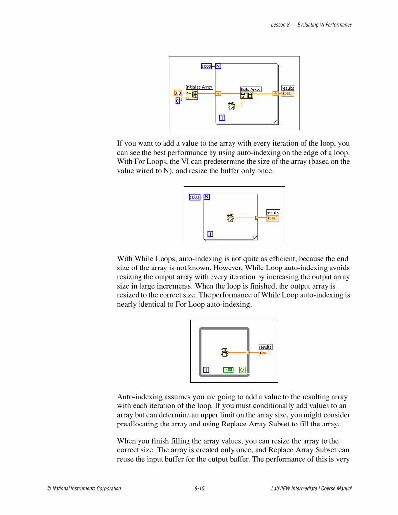
Lesson 8 Evaluating VI Performance
© National Instruments Corporation 8-15 LabVIEW Intermediate I Course Manual
If you want to add a value to the array with every iteration of the loop, you can see the best performance by using auto-indexing on the edge of a loop. With For Loops, the VI can predetermine the size of the array (based on the value wired to N), and resize the buffer only once.
With While Loops, auto-indexing is not quite as efficient, because the end size of the array is not known. However, While Loop auto-indexing avoids resizing the output array with every iteration by increasing the output array size in large increments. When the loop is finished, the output array is resized to the correct size. The performance of While Loop auto-indexing is nearly identical to For Loop auto-indexing.
Auto-indexing assumes you are going to add a value to the resulting array with each iteration of the loop. If you must conditionally add values to an array but can determine an upper limit on the array size, you might consider preallocating the array and using Replace Array Subset to fill the array.
When you finish filling the array values, you can resize the array to the correct size. The array is created only once, and Replace Array Subset can reuse the input buffer for the output buffer. The performance of this is very
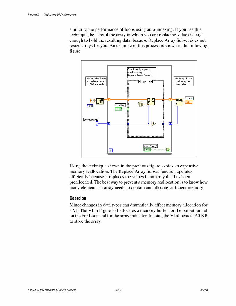
Lesson 8 Evaluating VI Performance
LabVIEW Intermediate I Course Manual 8-16 ni.com
similar to the performance of loops using auto-indexing. If you use this technique, be careful the array in which you are replacing values is large enough to hold the resulting data, because Replace Array Subset does not resize arrays for you. An example of this process is shown in the following figure.
Using the technique shown in the previous figure avoids an expensive memory reallocation. The Replace Array Subset function operates efficiently because it replaces the values in an array that has been preallocated. The best way to prevent a memory reallocation is to know how many elements an array needs to contain and allocate sufficient memory.
CoercionMinor changes in data types can dramatically affect memory allocation for a VI. The VI in Figure 8-1 allocates a memory buffer for the output tunnel on the For Loop and for the array indicator. In total, the VI allocates 160 KB to store the array.
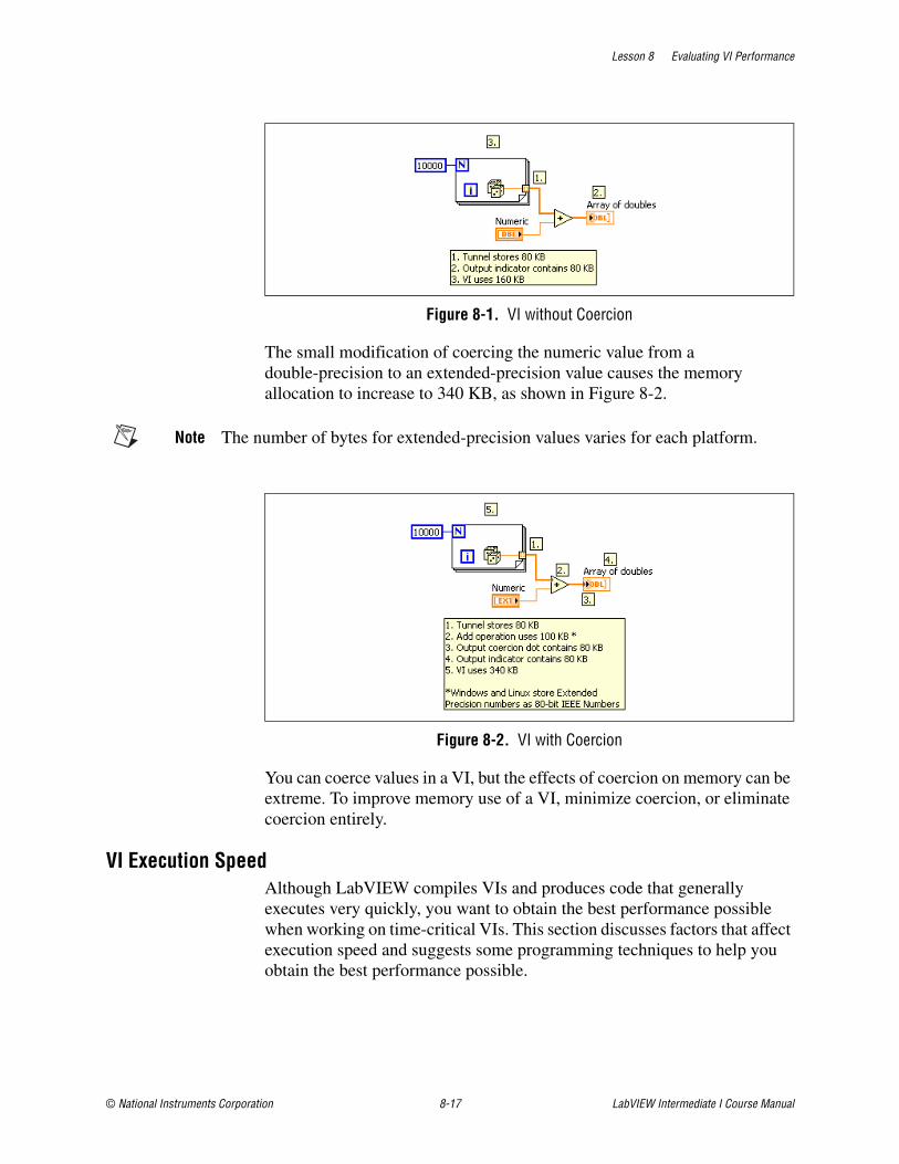
Lesson 8 Evaluating VI Performance
© National Instruments Corporation 8-17 LabVIEW Intermediate I Course Manual
Figure 8-1. VI without Coercion
The small modification of coercing the numeric value from a double-precision to an extended-precision value causes the memory allocation to increase to 340 KB, as shown in Figure 8-2.
Note The number of bytes for extended-precision values varies for each platform.
Figure 8-2. VI with Coercion
You can coerce values in a VI, but the effects of coercion on memory can be extreme. To improve memory use of a VI, minimize coercion, or eliminate coercion entirely.
VI Execution SpeedAlthough LabVIEW compiles VIs and produces code that generally executes very quickly, you want to obtain the best performance possible when working on time-critical VIs. This section discusses factors that affect execution speed and suggests some programming techniques to help you obtain the best performance possible.
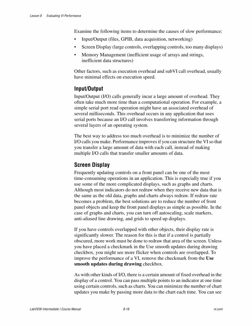
Lesson 8 Evaluating VI Performance
LabVIEW Intermediate I Course Manual 8-18 ni.com
Examine the following items to determine the causes of slow performance:
• Input/Output (files, GPIB, data acquisition, networking)
• Screen Display (large controls, overlapping controls, too many displays)
• Memory Management (inefficient usage of arrays and strings, inefficient data structures)
Other factors, such as execution overhead and subVI call overhead, usually have minimal effects on execution speed.
Input/OutputInput/Output (I/O) calls generally incur a large amount of overhead. They often take much more time than a computational operation. For example, a simple serial port read operation might have an associated overhead of several milliseconds. This overhead occurs in any application that uses serial ports because an I/O call involves transferring information through several layers of an operating system.
The best way to address too much overhead is to minimize the number of I/O calls you make. Performance improves if you can structure the VI so that you transfer a large amount of data with each call, instead of making multiple I/O calls that transfer smaller amounts of data.
Screen DisplayFrequently updating controls on a front panel can be one of the most time-consuming operations in an application. This is especially true if you use some of the more complicated displays, such as graphs and charts. Although most indicators do not redraw when they receive new data that is the same as the old data, graphs and charts always redraw. If redraw rate becomes a problem, the best solutions are to reduce the number of front panel objects and keep the front panel displays as simple as possible. In the case of graphs and charts, you can turn off autoscaling, scale markers, anti-aliased line drawing, and grids to speed up displays.
If you have controls overlapped with other objects, their display rate is significantly slower. The reason for this is that if a control is partially obscured, more work must be done to redraw that area of the screen. Unless you have placed a checkmark in the Use smooth updates during drawing checkbox, you might see more flicker when controls are overlapped. To improve the performance of a VI, remove the checkmark from the Use smooth updates during drawing checkbox.
As with other kinds of I/O, there is a certain amount of fixed overhead in the display of a control. You can pass multiple points to an indicator at one time using certain controls, such as charts. You can minimize the number of chart updates you make by passing more data to the chart each time. You can see
Lesson 8 Evaluating VI Performance
© National Instruments Corporation 8-19 LabVIEW Intermediate I Course Manual
much higher data display rates if you collect your chart data into arrays to display multiple points at a time, instead of displaying each point as it comes in.
When you design subVIs whose front panels are closed during execution, do not be concerned about display overhead. If the front panel is closed, you do not have the drawing overhead for controls, so graphs are no more expensive than arrays.
In multithreaded systems, you can use the Advanced»Synchronous Display shortcut menu item to set whether to defer updates for controls and indicators. In single-threaded execution, this item has no effect. However, if you turn this item on or off within VIs in the single-threaded version, those changes affect the way updates behave if you load those VIs into a multithreaded system.
By default, controls and indicators use asynchronous displays, which means that after the execution system passes data to front panel controls and indicators, it can immediately continue execution. At some point thereafter, the user interface system notices that the control or indicator needs to be updated, and it redraws to show the new data. If the execution system attempts to update the control multiple times in rapid succession, you might not see some of the intervening updates.
In most applications, asynchronous displays significantly speed up execution without affecting what the user sees. For example, you can update a Boolean value hundreds of times in a second, which is more updates than the human eye can discern. Asynchronous displays permit the execution system to spend more time executing VIs, with updates automatically reduced to a slower rate by the user interface thread.
If you want synchronous displays, right-click the control or indicator and select Advanced»Synchronous Display from the shortcut menu to place a checkmark next to the menu item.
Note Turn on synchronous display only when it is necessary to display every data value. Using synchronous display results in a large performance penalty on multithreaded systems.
You also can use the Defer Panel Updates property to defer all new requests for front panel updates.
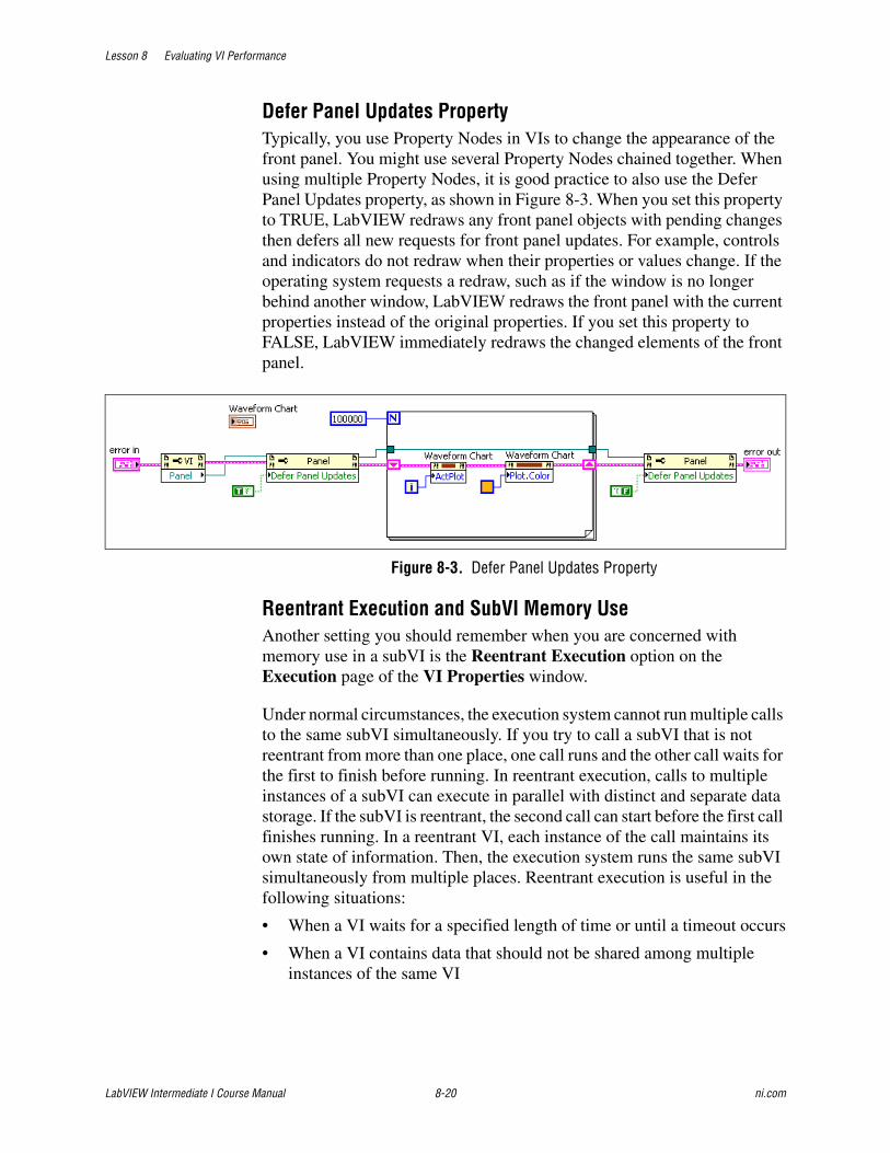
Lesson 8 Evaluating VI Performance
LabVIEW Intermediate I Course Manual 8-20 ni.com
Defer Panel Updates PropertyTypically, you use Property Nodes in VIs to change the appearance of the front panel. You might use several Property Nodes chained together. When using multiple Property Nodes, it is good practice to also use the Defer Panel Updates property, as shown in Figure 8-3. When you set this property to TRUE, LabVIEW redraws any front panel objects with pending changes then defers all new requests for front panel updates. For example, controls and indicators do not redraw when their properties or values change. If the operating system requests a redraw, such as if the window is no longer behind another window, LabVIEW redraws the front panel with the current properties instead of the original properties. If you set this property to FALSE, LabVIEW immediately redraws the changed elements of the front panel.
Figure 8-3. Defer Panel Updates Property
Reentrant Execution and SubVI Memory UseAnother setting you should remember when you are concerned with memory use in a subVI is the Reentrant Execution option on the Execution page of the VI Properties window.
Under normal circumstances, the execution system cannot run multiple calls to the same subVI simultaneously. If you try to call a subVI that is not reentrant from more than one place, one call runs and the other call waits for the first to finish before running. In reentrant execution, calls to multiple instances of a subVI can execute in parallel with distinct and separate data storage. If the subVI is reentrant, the second call can start before the first call finishes running. In a reentrant VI, each instance of the call maintains its own state of information. Then, the execution system runs the same subVI simultaneously from multiple places. Reentrant execution is useful in the following situations:
• When a VI waits for a specified length of time or until a timeout occurs
• When a VI contains data that should not be shared among multiple instances of the same VI

Lesson 8 Evaluating VI Performance
© National Instruments Corporation 8-21 LabVIEW Intermediate I Course Manual
To make a VI reentrant, select File»VI Properties, select Execution in the VI Properties dialog box, and place a checkmark in the Reentrant execution checkbox.
When you open a reentrant subVI from the block diagram, LabVIEW opens a clone of the VI instead of the source VI. The title bar of the VI contains (clone) to indicate that it is a clone of the source VI.
You can use the front panels of reentrant VIs the same way you can use the front panels of other VIs. To view the front panel of a reentrant VI from a clone of the reentrant VI, select View»Browse Relationships»Reentrant Original. Each instance of a reentrant VI has a front panel. You can use the VI Properties dialog box to set a reentrant VI to open the front panel during execution and optionally reclose it after the reentrant VI runs. You also can configure an Event structure case to handle events for front panel objects of a reentrant VI. The front panel of a reentrant VI also can be a subpanel.
You can use the VI Server to programmatically control the front panel controls and indicators on a reentrant VI at run time; however, you cannot edit the controls and indicators at run time. You also can use the VI Server to create a copy of the front panel of a reentrant VI at run time. To copy the front panel of a reentrant VI, use the Open VI Reference function to open a VI Server reference. Wire a strictly typed VI reference to the type specifier input or wire open for reentrant run to the option input. When you open a reference, LabVIEW creates a copy of the VI. You also can use the VI Server or the VI Properties dialog box to open the front panel of the reentrant VI.
The memory monitoring tools in LabVIEW do not report information on reentrant VIs. You must keep track of which subVIs have this feature enabled. Reentrant execution is typically used when you are calling a subVI in different locations at the same time and that subVI is storing data in an uninitialized shift register between each call. Otherwise, you might not need to configure subVIs for reentrant execution.

Lesson 8 Evaluating VI Performance
LabVIEW Intermediate I Course Manual 8-22 ni.com
Exercise 8-3 Concept: Methods of Updating Indicators
GoalLearn about the performance of different methods used to update indicators.
DescriptionThere are three primary methods of updating a value on a user interface:
• Wire data directly to an indicator—Fastest and preferred method of passing data to the user interface.
• Wire data to a local variable—Creating a local variable for the indicator and wiring data to the local variable is a good method for initializing data that is in a control.
• Wire data to a Value Property Node of the indicator—Use this method when you update the control or indicator through a control reference.
Each of these methods has performance differences. This VI demonstrates the performance differences of each of these methods.
1. Open Methods of Updating Indicators.vi located in the C:\Exercises\LabVIEW Intermediate I\Methods of Updating Indicators directory.
2. Open the block diagram and observe how this VI operates.
3. Run the VI for each of the methods by setting the Method enum, and running the VI. Observe how long the VI takes to run for each method.
End of Exercise 8-3
Lesson 8 Evaluating VI Performance
© National Instruments Corporation 8-23 LabVIEW Intermediate I Course Manual
Job AidUse the following checklist to identify and fix performance issues.
❑ Ensure that the code is correct before trying to improve performance.
❑ Use the Profile window to identify slow parts of the VI.
❑ Minimize memory reallocations.
❑ Minimize coercion dots.
❑ Minimize I/O overhead.
❑ Minimize front panel updates.
Lesson 8 Evaluating VI Performance
LabVIEW Intermediate I Course Manual 8-24 ni.com
Summary• Consider performance improvements only after the VI functions
correctly.
• Identify performance problems with the Profile window.
• Identify block diagram or front panel design issues using VI metrics.
• Interactively test performance and style issues using the VI Analyzer.

Lesson 8 Evaluating VI Performance
© National Instruments Corporation 8-25 LabVIEW Intermediate I Course Manual
Notes

Lesson 8 Evaluating VI Performance
LabVIEW Intermediate I Course Manual 8-26 ni.com
Notes
© National Instruments Corporation 9-1 LabVIEW Intermediate I Course Manual
9Implementing Documentation
This lesson describes techniques to implement documentation for the VI. It is important to provide meaningful documentation to support the users of the VI and other developers who might inherit the VI. You learn ideas for creating documentation standards for your own organization.
TopicsA. Designing DocumentationB. Developing User Documentation
C. Creating Help Files
D. Describing VIs, Controls, and Indicators

Lesson 9 Implementing Documentation
LabVIEW Intermediate I Course Manual 9-2 ni.com
A. Designing Documentation The quality goals of the project determine the format and detail level of the documentation you develop for requirements, specifications, and other design-related documentation. If the project must meet a quality standard such as the ISO 9000, the format and detail level of the documentation is different from the format and detail level of an internal project.
LabVIEW includes features that simplify the process of creating documentation for the VIs you design.
• History window—Use this window to record changes to a VI as you make them.
• Print dialog box —Use this dialog box to create printouts of the front panel, block diagram, connector pane, and description of a VI. You also can use it to print the names and descriptions of controls and indicators for the VI and the names and paths of any subVIs. You can print this information, generate text files, or generate HTML or RTF files that you can use to create compiled help files.
B. Developing User DocumentationOrganizing the documentation systematically helps users learn about the product, VI, or application. Different users have different documentation needs. End users of VIs fall into the following two classes—end users of top-level VIs and end users of subVIs. Each of these users have different documentation needs.
This section addresses techniques for creating and organizing documentation that helps both of these classes of users. The format of user documentation depends on the type of product you create.
Systematically Organizing Documentation To make documentation more helpful for the user, consider organizing the documentation in a systematic way. Divide the documentation into three categories—concepts, procedures, and reference material. Create documentation that reflects these three categories.
Documenting a Library of VIs If the software you are creating is a library of VIs for use by other developers, such as an instrument driver or add-on package, create documents with a format similar to the LabVIEW Help. Because the audience is other developers, assume the audience has a working knowledge of LabVIEW. Create documentation that contains an overview of the contents of the package, examples of how to use the subVIs, and a detailed description of each subVI.

Lesson 9 Implementing Documentation
© National Instruments Corporation 9-3 LabVIEW Intermediate I Course Manual
For each subVI, include information such as the VI name and description, a picture of the connector pane, and a picture of the data type description for each control and indicator on the connector pane.
To generate most of the documentation for VIs and controls, select File»VI Properties and select Documentation from the Category pull-down menu.
Select File»Print to print VI documentation in a format almost identical to the format used in the VI and function reference information in the LabVIEW Help. Use the Print dialog box to save the documentation to a file and to create documentation for multiple VIs at once.
Documenting an Application If you are developing an application for users who are unfamiliar with LabVIEW, the documentation requires more introductory material. Create a document that provides system requirements, basic installation instructions, and an overview about how the package works. If the package uses I/O, include hardware requirements and any configuration instructions the user must complete before using the application.
For each front panel with which the user interacts, provide a picture of the front panel and a description of the major controls and indicators. Organize the front panel descriptions in a top-down fashion, with the front panel the user sees first documented first. You also can use the Print dialog box to create this documentation.
Documenting a Design PatternWhen you implement a scalable architecture, you should always consider what scalability issues could arise. After you implement an architecture for an application, it is difficult to change the fundamental architecture. Choose good programming techniques to implement the scalable architecture because it is inevitable that you or another developer will need to change or modify the VI in the future. Applications and their uses evolve. To make sure that your chosen architecture does not need to be completely re-architected or re-written when you make changes, create proper documentation on the functionality of the architecture.
Place a diagram or description of the chosen architecture on the block diagram to illustrate its functionality and increase the readability of the design pattern. For example, embed an image of the state machine diagram inside the block diagram of a state machine design pattern to improve the readability of the VI, as shown in Figure 9-1.
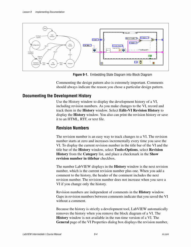
Lesson 9 Implementing Documentation
LabVIEW Intermediate I Course Manual 9-4 ni.com
Figure 9-1. Embedding State Diagram into Block Diagram
Commenting the design pattern also is extremely important. Comments should always indicate the reason you chose a particular design pattern.
Documenting the Development HistoryUse the History window to display the development history of a VI, including revision numbers. As you make changes to the VI, record and track them in the History window. Select Edit»VI Revision History to display the History window. You also can print the revision history or save it to an HTML, RTF, or text file.
Revision Numbers
The revision number is an easy way to track changes to a VI. The revision number starts at zero and increases incrementally every time you save the VI. To display the current revision number in the title bar of the VI and the title bar of the History window, select Tools»Options, select Revision History from the Category list, and place a checkmark in the Show revision number in titlebar checkbox.
The number LabVIEW displays in the History window is the next revision number, which is the current revision number plus one. When you add a comment to the history, the header of the comment includes the next revision number. The revision number does not increase when you save a VI if you change only the history.
Revision numbers are independent of comments in the History window. Gaps in revision numbers between comments indicate that you saved the VI without a comment.
Because the history is strictly a development tool, LabVIEW automatically removes the history when you remove the block diagram of a VI. The History window is not available in the run-time version of a VI. The General page of the VI Properties dialog box displays the revision number,
Configuration
HardwareComponent
ErrorHandler
FileHandler
Analyzer
Start
SaveData
ReadData
Error?
Error?
AcquireData
Error?
ConfigureHardware
ConfigureSystem
Error?
UserInterface
Lesson 9 Implementing Documentation
© National Instruments Corporation 9-5 LabVIEW Intermediate I Course Manual
even for VIs without block diagrams. Click the Reset button in the History window to erase the revision history and reset the revision number to zero.
C. Describing VIs, Controls, and IndicatorsIntegrate information for the user in each VI you create by using the VI description feature, by placing instructions on the front panel, and by including descriptions for each control and indicator.
Creating VI Descriptions Create and edit VI descriptions by selecting File»VI Properties and selecting Documentation from the Category pull-down menu. The VI description is often the only source of information about a VI available to the user. The VI description appears in the Context Help window when you move the cursor over the VI icon and in any VI documentation you generate.
Include the following items in a VI description:
• An overview of the VI
• Instructions for using the VI
• Descriptions of the inputs and outputs
Documenting Front Panels One way of providing important instructions is to place a block of text prominently on the front panel. A list of important steps is valuable. Include instructions such as, “Select File»VI Properties for instructions” or “Select Help»Show Context Help.” For long instructions, use a scrolling string control instead of a free label. When you finish entering the text, right-click the control and select Data Operations»Make Current Value Default from the shortcut menu to save the text.
If a text block takes up too much space on the front panel, use a Help button on the front panel instead. Include the instruction string in the help window that appears when the user clicks the Help button. Use the Window Appearance page in the VI Properties dialog box to configure this help window as either a dialog box that requires the user to click an OK button to close it and continue, or as a window the user can move anywhere and close anytime.
You also can use a Help button to open an entry in an online help file. Use the Help functions to open the Context Help window or to open a help file and link to a specific topic.
Lesson 9 Implementing Documentation
LabVIEW Intermediate I Course Manual 9-6 ni.com
Creating Control and Indicator Descriptions Include a description for every control and indicator. To create, edit, and view object descriptions, right-click the object and select Description and Tip from the shortcut menu. The object description appears in the Context Help window when you move the cursor over the object and in any VI documentation you generate.
Unless every object has a description, the user looking at a new VI has no choice but to guess the function of each control and indicator. Remember to enter a description when you create the object. If you copy the object to another VI, you also copy the description.
Every control and indicator needs a description that includes the following information:
• Functionality
• Data type
• Valid range (for inputs)
• Default value (for inputs)—You also can list the default value in parentheses as part of the control or indicator name.
• Behavior for special values (0, empty array, empty string, and so on)
• Additional information, such as if the user must set this value always, often, or rarely
Designate which inputs and outputs are required, recommended, and optional to prevent users from forgetting to wire subVI connections. To indicate the required, recommended, and optional inputs and outputs, right-click the connector pane, select This Connection Is from the shortcut menu, and select Required, Recommended, or Optional.
Lesson 9 Implementing Documentation
© National Instruments Corporation 9-7 LabVIEW Intermediate I Course Manual
Exercise 9-1 Document User Interface
GoalLearn techniques to document the user interface.
ScenarioDocument the user interface. You must document the front panel of every VI that you create.
DesignDocument the TLC Main VI. Documentation needs to include a VI description, and each control and indicator needs a meaningful description and tip.
Implementation1. Open the TLC Main VI.
2. Select File»VI Properties and select Documentation from the Category list. Insert the following documentation in the VI description section:
❑ Enter an overview of the VI
❑ Enter instructions about how to use the VI
❑ Click the OK button to close the Documentation page.
3. Include a description for every control and indicator. Right-click the object and select Description and Tip from the shortcut menu to create, edit, and view object descriptions. The object descriptions appear in the Context Help window when you move the cursor over the object and in any VI documentation you create.
Every control and indicator needs a description that includes the following information:
❑ Functionality
❑ Data type
❑ Valid range (for inputs)
❑ Default value (for inputs)

Lesson 9 Implementing Documentation
LabVIEW Intermediate I Course Manual 9-8 ni.com
You also can list the default value in parentheses as part of the control or indicator label.
❑ Behavior for special values (0, empty array, empty string, and so on)
4. Save the VI.
End of Exercise 9-1

Lesson 9 Implementing Documentation
© National Instruments Corporation 9-9 LabVIEW Intermediate I Course Manual
D. Creating Help FilesIf you have the right development tools, create online help or reference documents.
Use the Print dialog box to help you create the source material for the help documents.
After creating the source documents, use a help compiler to create the help document. If you need help files on multiple platforms, use a help compiler for the specific platform for which you want to generate help files.
You also can link to the help files directly from a VI. Link VIs to the Help menu using the Documentation page of the VI Properties dialog box. You also can use the Help functions to link to topics in specific help files programmatically.
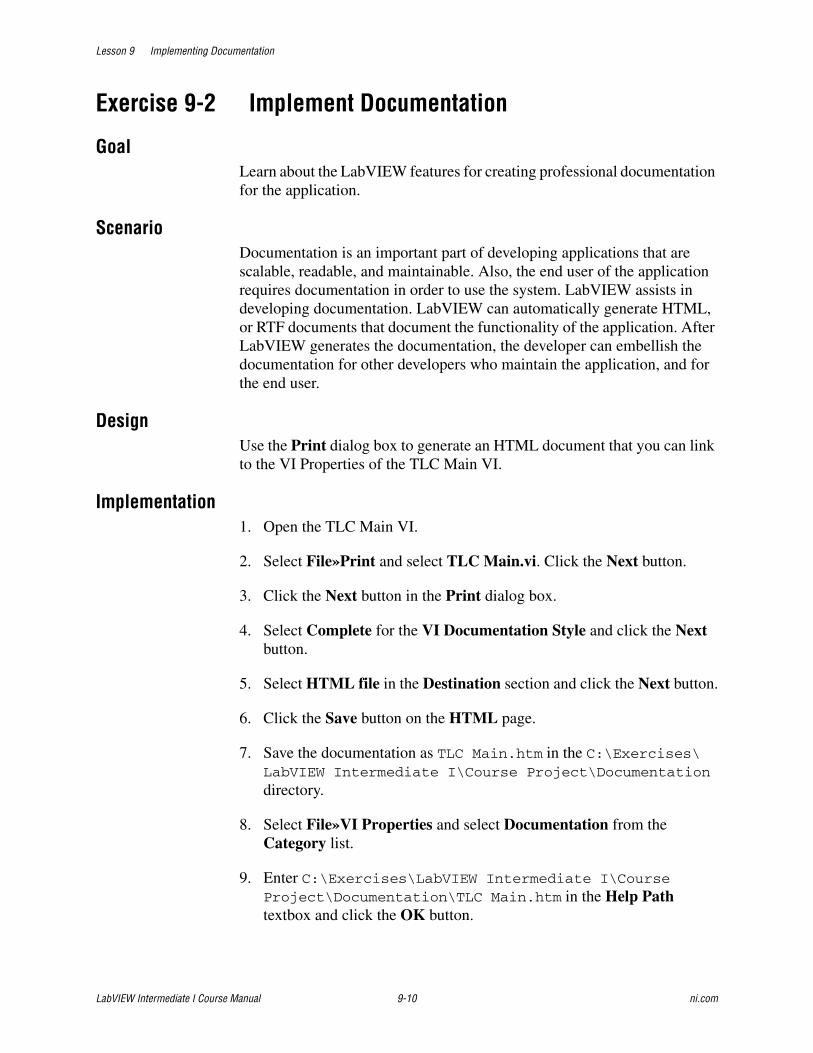
Lesson 9 Implementing Documentation
LabVIEW Intermediate I Course Manual 9-10 ni.com
Exercise 9-2 Implement Documentation
GoalLearn about the LabVIEW features for creating professional documentation for the application.
ScenarioDocumentation is an important part of developing applications that are scalable, readable, and maintainable. Also, the end user of the application requires documentation in order to use the system. LabVIEW assists in developing documentation. LabVIEW can automatically generate HTML, or RTF documents that document the functionality of the application. After LabVIEW generates the documentation, the developer can embellish the documentation for other developers who maintain the application, and for the end user.
DesignUse the Print dialog box to generate an HTML document that you can link to the VI Properties of the TLC Main VI.
Implementation1. Open the TLC Main VI.
2. Select File»Print and select TLC Main.vi. Click the Next button.
3. Click the Next button in the Print dialog box.
4. Select Complete for the VI Documentation Style and click the Next button.
5. Select HTML file in the Destination section and click the Next button.
6. Click the Save button on the HTML page.
7. Save the documentation as TLC Main.htm in the C:\Exercises\LabVIEW Intermediate I\Course Project\Documentation directory.
8. Select File»VI Properties and select Documentation from the Category list.
9. Enter C:\Exercises\LabVIEW Intermediate I\Course Project\Documentation\TLC Main.htm in the Help Path textbox and click the OK button.
Lesson 9 Implementing Documentation
© National Instruments Corporation 9-11 LabVIEW Intermediate I Course Manual
Testing1. Open the Context Help window.
2. Idle your mouse over the icon/connector pane of the TLC Main VI.
3. Click the Detailed help link in the Context Help window to load the documentation for the application.
End of Exercise 9-2
Lesson 9 Implementing Documentation
LabVIEW Intermediate I Course Manual 9-12 ni.com
Summary• Use the History window and Print dialog box to create a documentation
framework.
• Develop user documentation to help users learn about your VI.
• Ensure that all design patterns are fully documented and commented.
• Create, edit, and view VI descriptions by selecting File»VI Properties and selecting Documentation from the Category list. Include an overview of the VI, instructions about how to use the VI, and descriptions of the inputs and outputs.
• Document front panels by creating a Description and Tip for every control and indicator.
• Develop help files to create online help for your users.
• Describe all VIs, controls, and indicators.

Lesson 9 Implementing Documentation
© National Instruments Corporation 9-13 LabVIEW Intermediate I Course Manual
Notes

Lesson 9 Implementing Documentation
LabVIEW Intermediate I Course Manual 9-14 ni.com
Notes
© National Instruments Corporation 10-1 LabVIEW Intermediate I Course Manual
10Deploying the Application
This lesson describes techniques to improve the process of building a stand-alone LabVIEW application. This lesson provides a further exploration of the concepts covered in the LabVIEW Basics II: Development course on creating stand-alone applications. The focus of this lesson is to improve stand-alone applications, create professional applications, and provide a professional interface for deploying the application to other computers.
TopicsA. Implementing Code for Stand-Alone ApplicationsB. Building a Stand-Alone Application
C. Building an Installer
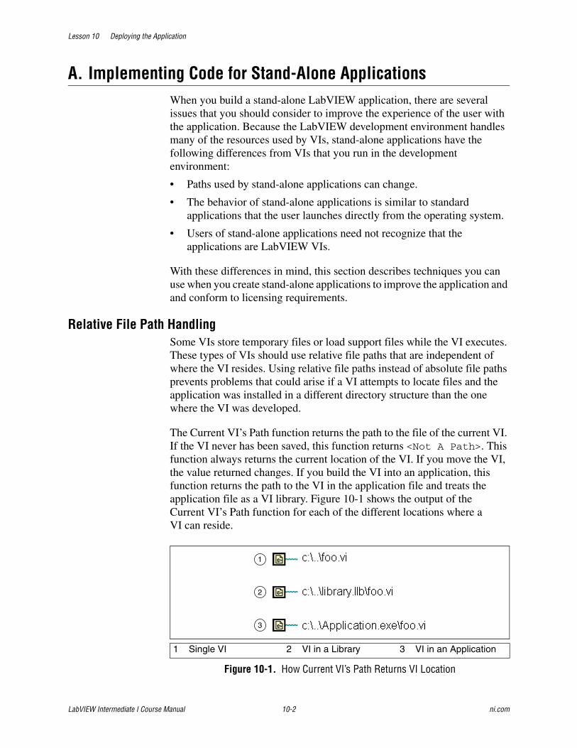
Lesson 10 Deploying the Application
LabVIEW Intermediate I Course Manual 10-2 ni.com
A. Implementing Code for Stand-Alone ApplicationsWhen you build a stand-alone LabVIEW application, there are several issues that you should consider to improve the experience of the user with the application. Because the LabVIEW development environment handles many of the resources used by VIs, stand-alone applications have the following differences from VIs that you run in the development environment:
• Paths used by stand-alone applications can change.
• The behavior of stand-alone applications is similar to standard applications that the user launches directly from the operating system.
• Users of stand-alone applications need not recognize that the applications are LabVIEW VIs.
With these differences in mind, this section describes techniques you can use when you create stand-alone applications to improve the application and and conform to licensing requirements.
Relative File Path HandlingSome VIs store temporary files or load support files while the VI executes. These types of VIs should use relative file paths that are independent of where the VI resides. Using relative file paths instead of absolute file paths prevents problems that could arise if a VI attempts to locate files and the application was installed in a different directory structure than the one where the VI was developed.
The Current VI’s Path function returns the path to the file of the current VI. If the VI never has been saved, this function returns <Not A Path>. This function always returns the current location of the VI. If you move the VI, the value returned changes. If you build the VI into an application, this function returns the path to the VI in the application file and treats the application file as a VI library. Figure 10-1 shows the output of the Current VI’s Path function for each of the different locations where a VI can reside.
Figure 10-1. How Current VI’s Path Returns VI Location
1 Single VI 2 VI in a Library 3 VI in an Application
1
2
3

Lesson 10 Deploying the Application
© National Instruments Corporation 10-3 LabVIEW Intermediate I Course Manual
If a VI uses the Current VI's Path function, make sure the function works as expected in the application or shared library. In an application or shared library, the Current VI's Path function returns the path to the VI in the application file and treats the application file as an LLB. For example, if you build foo.vi into an application, the function returns a path of C:\..\Application.exe\foo.vi, where C:\..\Application.exe represents the path to the application and its filename.
You must build code that has a relative file path independent of where the VI resides so that LabVIEW can access the necessary support and data files. One method to do this is to use the VI Server to return information about the properties of the LabVIEW application as shown in Figure 10-2.
Figure 10-2. Relative File Path VI
In Figure 10-2, VI Server determines the type of environment the VI is running in—as a stand-alone application or in the LabVIEW development environment. The Property Node returns the system type as an enumerated type. The Strip Path function strips the output of Current VI’s Path function by removing all the path information after the last backslash (\). Then the stripped path is placed into the Case structure where it is processed further. If the VI is running in the Run-Time Engine, which is necessary to execute LabVIEW-built applications and shared libraries, the name of the application is stripped. The stripped path is passed to the Build Path function, which appends a name (or relative path) to the existing path. If the VI is running in the development environment, there is no need to strip the path. Using relative file paths gives you more flexibility for deploying the application on other computers.
About Dialog BoxMost applications have an About dialog box that displays information about the application and the user or company that designed it. You can create a VI that LabVIEW runs when a user selects Help»About to display information about the stand-alone application you create. After the VI runs, LabVIEW closes the dialog box.
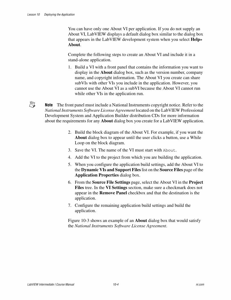
Lesson 10 Deploying the Application
LabVIEW Intermediate I Course Manual 10-4 ni.com
You can have only one About VI per application. If you do not supply an About VI, LabVIEW displays a default dialog box similar to the dialog box that appears in the LabVIEW development system when you select Help»About.
Complete the following steps to create an About VI and include it in a stand-alone application.
1. Build a VI with a front panel that contains the information you want to display in the About dialog box, such as the version number, company name, and copyright information. The About VI you create can share subVIs with other VIs you include in the application. However, you cannot use the About VI as a subVI because the About VI cannot run while other VIs in the application run.
Note The front panel must include a National Instruments copyright notice. Refer to the National Instruments Software License Agreement located on the LabVIEW Professional Development System and Application Builder distribution CDs for more information about the requirements for any About dialog box you create for a LabVIEW application.
2. Build the block diagram of the About VI. For example, if you want the About dialog box to appear until the user clicks a button, use a While Loop on the block diagram.
3. Save the VI. The name of the VI must start with About.
4. Add the VI to the project from which you are building the application.
5. When you configure the application build settings, add the About VI to the Dynamic VIs and Support Files list on the Source Files page of the Application Properties dialog box.
6. From the Source File Settings page, select the About VI in the Project Files tree. In the VI Settings section, make sure a checkmark does not appear in the Remove Panel checkbox and that the destination is the application.
7. Configure the remaining application build settings and build the application.
Figure 10-3 shows an example of an About dialog box that would satisfy the National Instruments Software License Agreement.
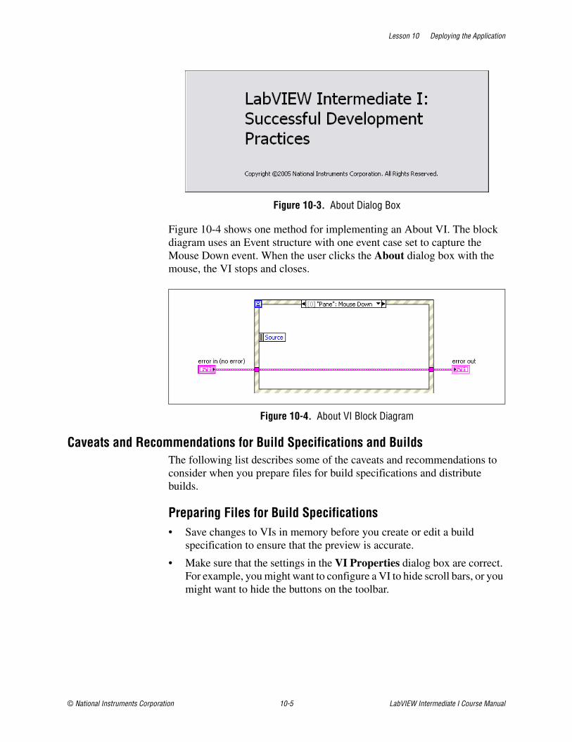
Lesson 10 Deploying the Application
© National Instruments Corporation 10-5 LabVIEW Intermediate I Course Manual
Figure 10-3. About Dialog Box
Figure 10-4 shows one method for implementing an About VI. The block diagram uses an Event structure with one event case set to capture the Mouse Down event. When the user clicks the About dialog box with the mouse, the VI stops and closes.
Figure 10-4. About VI Block Diagram
Caveats and Recommendations for Build Specifications and BuildsThe following list describes some of the caveats and recommendations to consider when you prepare files for build specifications and distribute builds.
Preparing Files for Build Specifications• Save changes to VIs in memory before you create or edit a build
specification to ensure that the preview is accurate.
• Make sure that the settings in the VI Properties dialog box are correct. For example, you might want to configure a VI to hide scroll bars, or you might want to hide the buttons on the toolbar.
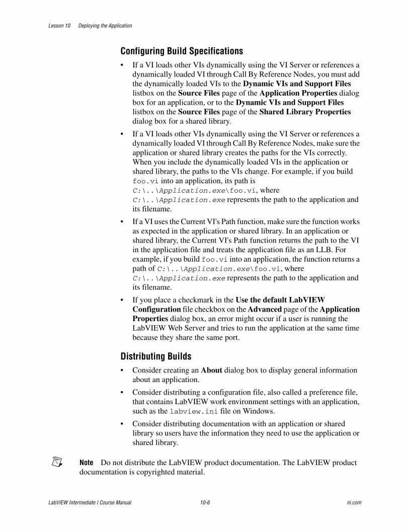
Lesson 10 Deploying the Application
LabVIEW Intermediate I Course Manual 10-6 ni.com
Configuring Build Specifications• If a VI loads other VIs dynamically using the VI Server or references a
dynamically loaded VI through Call By Reference Nodes, you must add the dynamically loaded VIs to the Dynamic VIs and Support Files listbox on the Source Files page of the Application Properties dialog box for an application, or to the Dynamic VIs and Support Files listbox on the Source Files page of the Shared Library Properties dialog box for a shared library.
• If a VI loads other VIs dynamically using the VI Server or references a dynamically loaded VI through Call By Reference Nodes, make sure the application or shared library creates the paths for the VIs correctly. When you include the dynamically loaded VIs in the application or shared library, the paths to the VIs change. For example, if you build foo.vi into an application, its path is C:\..\Application.exe\foo.vi, where C:\..\Application.exe represents the path to the application and its filename.
• If a VI uses the Current VI's Path function, make sure the function works as expected in the application or shared library. In an application or shared library, the Current VI's Path function returns the path to the VI in the application file and treats the application file as an LLB. For example, if you build foo.vi into an application, the function returns a path of C:\..\Application.exe\foo.vi, where C:\..\Application.exe represents the path to the application and its filename.
• If you place a checkmark in the Use the default LabVIEW Configuration file checkbox on the Advanced page of the Application Properties dialog box, an error might occur if a user is running the LabVIEW Web Server and tries to run the application at the same time because they share the same port.
Distributing Builds• Consider creating an About dialog box to display general information
about an application.
• Consider distributing a configuration file, also called a preference file, that contains LabVIEW work environment settings with an application, such as the labview.ini file on Windows.
• Consider distributing documentation with an application or shared library so users have the information they need to use the application or shared library.
Note Do not distribute the LabVIEW product documentation. The LabVIEW product documentation is copyrighted material.

Lesson 10 Deploying the Application
© National Instruments Corporation 10-7 LabVIEW Intermediate I Course Manual
Considerations for the LabVIEW Run-Time Engine• The LabVIEW Run-Time Engine must be installed on any computer on
which users run the application or shared library. You can distribute the LabVIEW Run-Time Engine with the application or shared library. (Windows) You also can include the LabVIEW Run-Time Engine in an installer. You must log on as an Administrator or a user with administrator privileges to run an installer you build using the Application Builder.
• Some VI Server properties and methods are not supported in the LabVIEW Run-Time Engine. Avoid using these properties and methods in the VIs you include in an application or shared library.
• Incorporate error handling into the VIs of the application because LabVIEW does not display automatic error handling dialog boxes in the LabVIEW Run-Time Engine.
• If the VI uses custom run-time menus, make sure the application menu items that the VI uses are available in the LabVIEW Run-Time Engine.
• When you close all front panels in an application, the application stops. If the VI you build into the application contains code that executes after the last front panel closes, this code does not execute in the application. Avoid writing block diagram code that executes after the last front panel closes.
• If you reference a VI in an application using the Call By Reference Node, if a VI uses Property Nodes to set front panel properties, or if a front panel appears to users, do not place a checkmark in the Remove Panel checkbox for that VI from the VI Settings section on the Source File Settings page of the Application Properties dialog box. If you remove the front panel, the Call By Reference Node or Property Nodes that refer to the front panel return errors that might affect the behavior of the application.
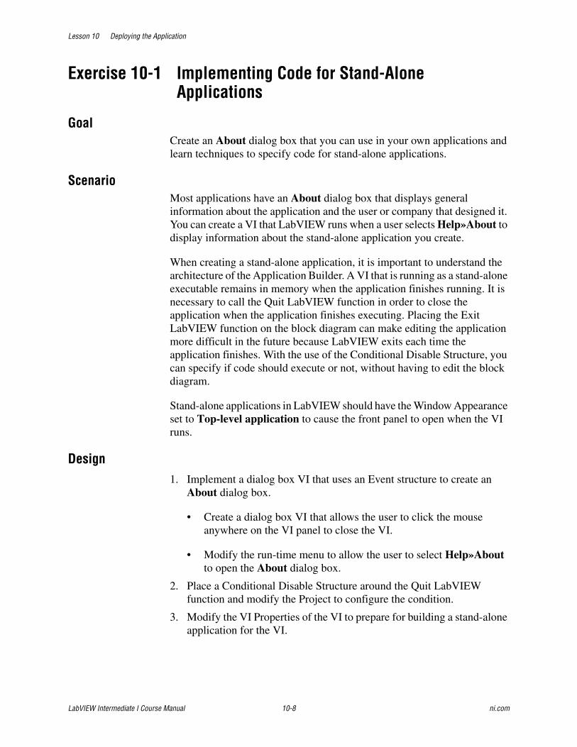
Lesson 10 Deploying the Application
LabVIEW Intermediate I Course Manual 10-8 ni.com
Exercise 10-1 Implementing Code for Stand-Alone Applications
GoalCreate an About dialog box that you can use in your own applications and learn techniques to specify code for stand-alone applications.
ScenarioMost applications have an About dialog box that displays general information about the application and the user or company that designed it. You can create a VI that LabVIEW runs when a user selects Help»About to display information about the stand-alone application you create.
When creating a stand-alone application, it is important to understand the architecture of the Application Builder. A VI that is running as a stand-alone executable remains in memory when the application finishes running. It is necessary to call the Quit LabVIEW function in order to close the application when the application finishes executing. Placing the Exit LabVIEW function on the block diagram can make editing the application more difficult in the future because LabVIEW exits each time the application finishes. With the use of the Conditional Disable Structure, you can specify if code should execute or not, without having to edit the block diagram.
Stand-alone applications in LabVIEW should have the Window Appearance set to Top-level application to cause the front panel to open when the VI runs.
Design1. Implement a dialog box VI that uses an Event structure to create an
About dialog box.
• Create a dialog box VI that allows the user to click the mouse anywhere on the VI panel to close the VI.
• Modify the run-time menu to allow the user to select Help»About to open the About dialog box.
2. Place a Conditional Disable Structure around the Quit LabVIEW function and modify the Project to configure the condition.
3. Modify the VI Properties of the VI to prepare for building a stand-alone application for the VI.

Lesson 10 Deploying the Application
© National Instruments Corporation 10-9 LabVIEW Intermediate I Course Manual
Implementation
About Dialog Box1. Create a dialog box VI that allows the user to click the mouse button
anywhere on the VI panel to close the VI.
❑ Create a new VI.
❑ Set the Window Appearance of the VI to Dialog by selecting File»VI Properties and modifying the Window Appearance category.
❑ Place any free text or images you want on the front panel of the VI.
❑ Place error clusters on the front panel.
❑ Switch to the block diagram and build the code that allows the user to click the mouse button anywhere on the VI, as shown in Figure 10-5.
Figure 10-5. About VI Block Diagram
❑ Place an Event structure on the block diagram and create an Event case for the Mouse Down event for the <Pane> event source.
❑ Wire the error clusters through the Event structure on the block diagram.
❑ Save the VI as About.vi in the C:\Exercises\LabVIEW Intermediate I\Course Project\Modules\About directory.
❑ Add an About folder below the Modules folder in the Project Explorer window.
❑ Place the About.vi in the About folder in the Project Explorer window.
2. Modify the TLC Main VI so that the Run-Time Menu contains Help»About LabVIEW. This displays the About dialog box in the
Lesson 10 Deploying the Application
LabVIEW Intermediate I Course Manual 10-10 ni.com
stand-alone application when the user selects Help»About. Figure 10-6 shows the completed Run-Time Menu Editor.
Figure 10-6. Run-Time Menu Editor
❑ Open the Menu Editor by selecting Edit»Run-Time Menu.
❑ Add the Help menu item by adding a User Item for Help, with the Item Name set to _Help and the Item Tag set to Help.
❑ Verify that the Help menu item is at the same level as the File menu item.
3. Add the About LabVIEW item by selecting Edit»Insert Application Item»Help»About LabVIEW.
4. Save the Run-Time Menu.
Quit LabVIEW FunctionUse the Quit LabVIEW function to cause LabVIEW to finish executing when the application completes. You can use a Conditional Disable Structure to prevent the Quit LabVIEW function from executing when the application is running in the development environment, as shown in Figure 10-7.

Lesson 10 Deploying the Application
© National Instruments Corporation 10-11 LabVIEW Intermediate I Course Manual
Figure 10-7. Conditional Disable Structure Enclosing the Quit LabVIEW Function
1. Right-click TLC.lvproj in the Project Explorer window and select Properties from the shortcut menu.
2. Select Conditional Disable Symbols from the Category list, add a new symbol with the Symbol name DEPLOY and the Value TRUE.
3. Modify the TLC Main VI by placing the Quit LabVIEW function on the block diagram. The Quit LabVIEW function must be the last function that executes with the application as shown in Figure 10-7.
4. Place a Conditional Disable Structure around the Quit LabVIEW function and wire the error cluster to the border of the Conditional Disable Structure.
5. Right-click the border of the Conditional Disable Structure and select Edit Condition For This Subdiagram from the shortcut menu.
6. Select DEPLOY for the Symbol.
7. Enter TRUE for the Value.
8. Remove the checkmark from the Make Default? checkbox.
9. Click the OK button.
10. Right-click the Conditional Disable Structure and select Add Subdiagram After from the shortcut menu.
11. Select DEPLOY for the Symbol.
12. Enter FALSE for the Value.
13. Place a checkmark in the Make Default? checkbox.
14. Click the OK button.
Lesson 10 Deploying the Application
LabVIEW Intermediate I Course Manual 10-12 ni.com
LabVIEW only executes the Quit LabVIEW function if the Project DEPLOY Conditional Symbol is set to TRUE.
Window Appearance1. Select File»VI Properties and select Window Appearance from the
Category list.
2. Select Top-level application window and click the OK button.
3. Save the TLC Main VI.
End of Exercise 10-1

Lesson 10 Deploying the Application
© National Instruments Corporation 10-13 LabVIEW Intermediate I Course Manual
B. Building a Stand-Alone ApplicationYou can use the Application Builder tools to create a build specification for and build a stand-alone application (EXE). Before you create a build specification or start the build process, review the Caveats and Recommendations for Build Specifications and Builds section of this lesson.
Note The LabVIEW Professional Development System includes the Application Builder. If you use the LabVIEW Base Package or Full Development System, you can purchase the Application Builder separately by visiting ni.com.
Preparing VIs for Build SpecificationsComplete the following steps to prepare VIs you want to use to build a source distribution, or if you are using the Application Builder, to build a stand-alone application or shared library or to convert a .bld file from a previous version of LabVIEW.
1. Open the top-level VIs you want to use in the build, and open any VIs you want to load dynamically using the VI Server or Call By Reference Nodes.
2. From an open VI, press the <Ctrl-Shift> keys while you click the Run button to recompile all VIs in memory.
3. Select File»Save All to save all VIs in memory, then close the VIs.
Creating Build Specifications for Stand-Alone Applications
Use Build Specifications in the Project Explorer window to create build specifications for source distributions and other types of LabVIEW builds. A build specification contains all the settings for the build, such as files to include, directories to create, and settings for directories of VIs.
You must create build specifications in the Project Explorer window. Expand My Computer, right-click Build Specifications, and select New and the type of build you want to configure from the shortcut menu. Use the pages in the Source Distribution Properties, Application Properties, Shared Library Properties, (Windows) Installer Properties, or Zip File Properties dialog boxes to configure settings for the build specification. After you define these settings, click the OK button to close the dialog box and update the build specification in the project. The build specification appears under Build Specifications. Right-click a specification and select Build from the shortcut menu to complete the build.
Review the caveats and recommendations for applications and shared libraries and for installers before you create build specifications with the Application Builder.
Lesson 10 Deploying the Application
LabVIEW Intermediate I Course Manual 10-14 ni.com
Configuring Application PropertiesUse the Application Properties dialog box to access and configure settings for a stand-alone application. The Application Properties dialog box contains the following pages, which you can use to configure the settings for the build.
Application InformationThe Application Information page includes the following components:
• Build specification name—Specifies the name of the build specification for the application, installer, shared library, source distribution, or zip file. The name appears under Build Specifications in the Project Explorer window. Do not duplicate build specification names within a LabVIEW project.
• Target filename—Specifies the filename for the application. Applications must have a .exe extension.
• Application destination directory—Specifies the location to build the application. You can enter a path or use the Browse button to navigate to and select the location.
• Version Number—Contains the version number to associate with the application or shared library.
– Major—Contains the component of the version number that indicates a major revision.
– Minor—Contains the component of the version number that indicates a minor revision.
– Fix—Contains the component of the version number that indicates a revision to fix problems.
– Build—Contains the component of the version number that indicates a specific build.
• Description—Specifies information that you want to provide to users about the application or shared library.
• Product name—Specifies the name of the application or shared library that you want to display to users.
• Legal copyright—Specifies the copyright statement to include with the application or shared library.
• Company name—Specifies the name of the company you want to associate with the application.
• Internal name—Specifies a name to associate with the application or shared library for internal use.
Lesson 10 Deploying the Application
© National Instruments Corporation 10-15 LabVIEW Intermediate I Course Manual
Source FilesThe Source Files page includes the following components:
• Project Files—Displays a list of items under My Computer node in the Project Explorer window. Click the arrow buttons next to the Startup VIs and Dynamic VIs and Support Files listboxes to add selected files from Project Files to those lists or to remove selected files from the listboxes.
• Startup VIs—Specifies the startup VIs, which are top-level VIs, to use in the application. You must define at least one VI as a startup VI. Startup VIs display and run when you launch the application. Click the arrow buttons next to the Startup VIs listbox to add selected VIs from the Project Files listbox or to remove selected VIs from the Startup VIs listbox. When you add a VI to an application as a startup VI, the application also includes the dependencies of the VI. When you add a folder, you add all items in the folder and cannot remove individual items.
• Dynamic VIs and Support Files—Specifies the dynamic VIs and support files always to include in the application, even if the startup VIs do not contain references to the files. Click the arrow buttons next to the Dynamic VIs and Support Files listbox to add selected files from the Project Files listbox or to remove selected files from the Dynamic VIs and Support Files listbox. When you add a folder to the listbox, you add all items in the folder and cannot remove individual items.
Dynamic VIs are VIs that LabVIEW dynamically calls through the VI Server. Support files are non-VI files, such as drivers, text files, help files, and .NET assemblies that the application uses.
DestinationsThe Destinations page includes the following components:
• Destinations—Specifies the destination directories in which you want to include the files that the build generates. Click the New Destination and Remove Destination buttons to add and delete directories from the list.
• New Destination—Adds a custom destination directory to the Destinations listbox.
• Remove Destination—Removes the selected destination directory from the Destinations listbox. You cannot remove the default destination directory or the support directory.
• Destination label—Specifies the name that the dialog box uses for the directory selected in the Destinations listbox. Edit the label if you want to change the name. You cannot change the name of the default
Lesson 10 Deploying the Application
LabVIEW Intermediate I Course Manual 10-16 ni.com
destination directory or the support directory. Editing the destination label has no effect on the directory name on disk.
• Destination path—Specifies the path to the directory you select in the Destinations listbox. Click the Browse button to navigate to and select a path. If you change the path of the default destination directory, any destinations that are subdirectories automatically update to reflect the new path.
• Destination is LLB—Place a checkmark in this checkbox if you want the specified destination directory to be an LLB file.
Source File SettingsThe Source File Settings page includes the following components:
• Project Files—Displays the tree view of items under My Computer in the Project Explorer window.
• Inclusion Type—Appears if you select a VI in the Project Files tree. Specifies whether you want to include the selected VI as a startup VI, a dynamic VI, a support file, or a file included in the application only if referenced.
– Startup VI—Sets the VI as a startup VI in the application.
– Always include—Sets the file as a dynamic VI or support file that the application uses.
– Include only if referenced—Sets the file as a type that is included in the application only if referenced.
• Destination—Appears when you select a VI in the Project Files tree. Sets the destination directory for the selected VI. The options in the Destination ring control correspond to the options in the Destination label text box on the Destinations page of the Application Properties dialog box.
• VI Settings—Appears when you select a VI in the Project Files tree. Specifies the properties for the selected VI. The default uses the property settings contained in the VI.
• Set inclusion type for all contained items—Appears when you select a folder in the Project Files tree. Place a checkmark in the checkbox to specify how to include the items in the selected folder in the application.
– Startup VI (always include non-VIs)—Sets the VIs in the folder as startup VIs and sets non-VIs as support files in the application.
– Always include—Sets the items as dynamic VIs or support files in the application.
– Include only if referenced—Includes only items in the folder that other items in the application reference.
Lesson 10 Deploying the Application
© National Instruments Corporation 10-17 LabVIEW Intermediate I Course Manual
• Set destination for all contained items—Appears when you select a folder in the Project Files tree. Place a checkmark in the checkbox if you want to set the destination directory for the items in the selected folder. When you place a checkmark in the checkbox, a ring control activates that you can use to select the destination directory. The options in the ring control correspond to the options in the Destination label text box on the Destinations page of the Application Properties dialog box.
• Set properties for all contained VIs—Appears when you select a folder in the Project Files tree. Place a checkmark in the checkbox if you want to specify VI properties for VIs in the selected folder. The settings apply to all VIs in the selected folder. You cannot specify settings for individual VIs in the folder.
• Include even if not referenced by other files—Appears when you select a non-VI file in the Project Files tree. Place a checkmark in the checkbox to include the file as a support file in the application or shared library even if no other files include a reference to it.
• Destination directory—Appears when you select a non-VI file in the Project Files tree. Sets the destination directory for the selected file. The default is the support directory. The options in the Destination directory ring control correspond to the options in the Destination label text box on the Destinations page of the Application Properties dialog box. However, invalid destinations appear disabled, such as LLB files for non-VIs.
IconWhen you create an application, you want it to have a professional appearance. One way to make your application look more professional is to provide a custom icon for the application. LabVIEW applications default to the standard LabVIEW icon, shown at left, which does not give the customer an idea of the functionality of your application.
Use the Icon page of the Application Properties dialog box to select the icon file (.ico) to use for a stand-alone application. You can use the default LabVIEW icon, select a custom icon file, or create an icon file. The page displays previews of 32 × 32 and 16 × 16 pixel icons in color and in black and white.
The Icon page includes the following components:
• Use the default LabVIEW icon file—Indicates whether to use the standard LabVIEW icon for the application. Remove the checkmark from the checkbox if you want to select an icon file from within the project.
• Icon file in project—Specifies the icon file (.ico) to use for the application. LabVIEW can import black-and-white and color icons in
Lesson 10 Deploying the Application
LabVIEW Intermediate I Course Manual 10-18 ni.com
two resolutions, 16 × 16 pixel icon and 32 × 32 pixel icon, for a total of four possible icons. Click the Browse Project button to open the Select Project File dialog box, which you can use to select an icon file in the project. If no icon files exist in the project, you cannot open the Select Project File dialog box.
• Icon Editor—Launches the Icon Editor dialog box, which you can use to create or edit an icon file.
You also can use a third-party icon editor to create icons. Refer to the Icon Art Glossary at ni.com for standard graphics to use in a VI icon. You also can use the icon creation tool in LabWindows™/CVI™.
AdvancedThe Advanced page includes the following components.
• Pass all command line arguments to application—Passes all arguments as user-defined arguments to the application when you launch it from the command line. If you remove the checkmark from this checkbox, only the arguments after two hyphens (--) in the command line pass to the application as user-defined arguments. Use the Application:Command Line Arguments property to read the user-defined command-line arguments passed when the application launches.
• Enable debugging—Enables debugging for the application or shared library.
• Wait for debugger on launch—Sets the application or shared library to load but not run until the user enables it to run through the LabVIEW debugging controls. Place a checkmark in the Enable debugging checkbox to activate this option.
• Disconnect type definitions and remove unused polymorphic VI instances—Disconnects type definitions and removes unused polymorphic VI instances and their subVIs from a stand-alone application, shared library, or source distribution build to reduce the size of the application or shared library. If you remove the checkmark from this checkbox, the build includes type definitions and all instances of the polymorphic VIs (and their subVIs) regardless of whether they are called.
• Copy error code files—Adds copies of XML-based LabVIEW error code text files from the project\errors and user.lib\errors folders to the application or shared library.
• Use the default LabVIEW Configuration file (LabVIEW.ini)—Associates the LabVIEW configuration file with the application. If you remove the checkmark from the checkbox, specify a
Lesson 10 Deploying the Application
© National Instruments Corporation 10-19 LabVIEW Intermediate I Course Manual
configuration file to use in the Configuration file in project path control.
• Configuration file in project—Specifies the configuration file to use with the application if you do not enable Use the default LabVIEW Configuration file. Click the Browse Project button to open the Select Project File dialog box, which you can use to select a .ini file in the project. If no .ini files exist in the project, you cannot open the Select Project File dialog box.
• Use the default project alias file—Associates the project alias file with the application. If you remove the checkmark from the checkbox, specify an alias file to use in Alias file in project.
• Alias file in project—Specifies the alias file to use with the application if you do not enable Use the default project alias file. Click the Browse button to display the Select Project File dialog box, which you can use to select a file.
• Enable ActiveX server—Enables the ActiveX server so the application can respond to requests from ActiveX clients. The functionality of the ActiveX server in the application is a subset of the LabVIEW ActiveX server. When you build an application myapp.exe, Application Builder also creates an ActiveX type library myapp.tlb. The type library defines an application class and a virtual instrument class and exports both Application properties and methods and VI properties and methods. When you distribute the application, include the type library with the executable file.
The name of the application that you enter in the ActiveX server name text box uniquely identifies the application in the system registry. After you build the application, run it at least once to enable registry with the system. After the application is registered, ActiveX clients access the server objects using progIDs. For example, if the ActiveX server name is myapp, clients instantiate an application object using the progID myapp.application.
If you are packaging the application into an installer build specification, place a checkmark in the Register COM checkbox for the application file on the Source File Settings page of the Installer Properties dialog box so the installer registers the ActiveX server.
• ActiveX server name—Specifies the prefix of the progID for the application. This text box is enabled when you place a checkmark in the Enable ActiveX server checkbox.
Run-Time LanguagesUse this page of the Application Properties dialog box to set the language preferences for a stand-alone application. You can select from all languages that LabVIEW supports.
Lesson 10 Deploying the Application
LabVIEW Intermediate I Course Manual 10-20 ni.com
The language preferences apply to aspects of the stand-alone application that the LabVIEW Run-Time Engine affects, such as dialog boxes and menus. These items appear in the default language you select. Users can configure language settings to change the default language to any of the supported languages you select.
The Run-Time Languages page includes the following components.
• Support all languages—Enables support for all languages that LabVIEW supports in the application or shared library. Remove the checkmark from the checkbox if you want to specify the supported languages.
• Default language—Specifies the default language that the application or shared library supports if you remove the checkbox from the Support all languages checkbox.
• Supported languages—Lists the languages that the application or shared library supports if you remove the checkbox from the Support all languages checkbox.
PreviewUse the Preview page of the Application Properties dialog box to see a preview of the stand-alone application build.
Note Save changes to VIs in memory to ensure that the preview is accurate.
• Generate Preview—Creates a preview of the build that displays in Generated Files.
• Generated Files—Displays a preview of the directory structure and filenames in the build. Use this preview to determine if you need to change file destinations or other settings.
Lesson 10 Deploying the Application
© National Instruments Corporation 10-21 LabVIEW Intermediate I Course Manual
Exercise 10-2 Create a Stand-Alone Application
GoalCreate a build specification for and build a stand-alone application (EXE) in LabVIEW.
ScenarioCreating a stand-alone application is important for distributing and deploying your application. It is also a step in the creation of a professional installer.
DesignUse the Application (EXE) Build Specifications to create a stand-alone application for the Theatre Light Controller.
Implementation1. Create a stand-alone application of the Theatre Light Controller.
❑ Open the TLC.lvproj.
❑ Right click Build Specifications and select New»Application (EXE) from the shortcut menu to open the Application Properties dialog box.
❑ On the Application Information page, specify a Build specification name and Target filename.
❑ Set the Application destination directory to C:\Exercises\LabVIEW Intermediate I\Course Project\Builds\Executable.
❑ Select the Source Files page and select TLC Main.vi in the Project Files listbox. Click the right arrow to place the VI in the Startup VIs listbox.
❑ Select About.vi in the Modules»About folder and click the right arrow to place the VI in the Dynamic VIs and Support Files listbox.
❑ Select the Icon page and create a 16 color icon for both the 32 × 32 and 16 × 16 icons. Save the icon in the C:\Exercises\LabVIEW Intermediate I\Course Project\Icons directory.
❑ Select the Preview page and click the Generate Preview button to preview the output of the Build Specification.

Lesson 10 Deploying the Application
LabVIEW Intermediate I Course Manual 10-22 ni.com
❑ Click the OK button.
2. Right-click the build specification that you just created and select Build from the shortcut menu.
Testing1. Navigate to the directory you specified for the destination directory and
run the executable.
End of Exercise 10-2
Lesson 10 Deploying the Application
© National Instruments Corporation 10-23 LabVIEW Intermediate I Course Manual
C. Building an InstallerYou can use the Application Builder to build an installer for files in a LabVIEW project or for a stand-alone application you created with a build specification. Use installers to distribute stand-alone applications, shared libraries, and source distributions that you create with the Application Builder. Installers that include the LabVIEW Run-Time Engine are useful if you want users to be able to run applications or use shared libraries without installing LabVIEW.
Before you create a build specification or start the build process, review the Caveats and Recommendations for Building Installers.
Caveats and Recommendations for Building InstallersThe following list describes some of the caveats and recommendations to consider when you build an installer.
• When you select files to include in the installer build from the page of the Installer Properties dialog box, you cannot select part of a build specification or a LabVIEW project library. You must include or exclude build specifications and project libraries as a whole. The entire specification or project library appears in the Destination View directory.
• If you want to include a project library in the installer build, make sure the project library does not include files on a network or other files with links that will break if moved. You cannot copy a project library from the Project View directory to the Destination View directory if any of the files are on different drives, or if the files do not share a common path with the LabVIEW project file (.lvproj).
• When you add a National Instruments product installer to the installer build, you are adding only the components of the installer that you installed on the computer you are using. When users run the installer you built, the installer might remove components of the product from the user computer that are not part of the installer. To minimize the risk of removing product components on user computers, ensure you have a complete and up-to-date installation of the product on the computer you are using, including all optional components, before you add the product installer to the build.
• You can include custom error codes in the installer. The [LV80RTEDIR] folder in the Destination View directory corresponds to the Shared\LabVIEW Run-Time\8.0 directory. If you place a checkmark in the Install custom error code files? checkbox on the Advanced page, the installer build includes all error code files from labview\project\errors and labview\user.lib\errors and

Lesson 10 Deploying the Application
LabVIEW Intermediate I Course Manual 10-24 ni.com
installs them in the Shared\LabVIEW Run-Time\8.0\errors directory.
• Use the [LVDIR] folder in the Destination View directory to add files to install in the directory of the latest version of LabVIEW that the user has installed.
• The folders in the Destination View directory that do not have an LV prefix correspond to Microsoft Installer (MSI) properties that install files in the following locations.
– [DesktopFolder]—Files you include in this folder install to the Windows desktop of the current Windows user.
– [PersonalFolder]—Files you include in this folder install to the personal folder, such as My Documents, of the current Windows user.
– [ProgramFilesFolder]—Files you include in this folder install to the Program Files folder.
– [TempFolder]—Files you include in this folder install to the Temp folder of the current Windows user.
– [WindowsFolder]—Files you include in this folder install to the Windows folder.
– [SystemFolder]—Files you include in this folder install to the system32 folder on Windows.
– [WindowsVolume]—Files you include in this folder install to the root of the drive where Windows is installed, such as C:\.
Refer to the Microsoft Installer documentation on the Microsoft Web site for more information about using these folders.
Creating Build Specifications for InstallersExpand My Computer. Right-click Build Specifications and select New»Installer from the shortcut menu to display the Installer Properties dialog box. Use this dialog box to create or configure settings for an installer.
Configuring Installer PropertiesThe Installer Properties dialog box contains the following pages, which you can use to configure the settings for the installer.
Product InformationUse this page of the Installer Properties dialog box to name the product for which you are building an installer, select the location to build the installer, and enter version information.

Lesson 10 Deploying the Application
© National Instruments Corporation 10-25 LabVIEW Intermediate I Course Manual
This page includes the following components:
• Build specification name—Specifies the name of the build specification for the application, installer, shared library, source distribution, or zip file. The name appears under Build Specifications in the Project Explorer window. Do not duplicate build specification names within a LabVIEW project.
• Product name—Specifies the name of the installer that you want to display to users. The name appears in the list of applications in the Windows Add/Remove Programs dialog box. The product name corresponds to the [ProductName] Microsoft Installer (MSI) property.
• Installer destination—Determines the location to build the installer. You can enter a path or use the Browse button to navigate to and select the location.
• Media spanning—Specifies the type of media on which you want to store the product, such as a CD or DVD. The final installer distribution is divided into directories that fit on the required media type, such as 650 MB folders for a CD.
• Product version—Specifies the current software version number. The installer uses this number to check for a current installation and to check for upgrades. You must increment the version number if you want to create upgrade versions of the installer that are capable of overwriting previous installers. The product version corresponds to the [ProductVersion] Microsoft Installer (MSI) property.
• Language—Specifies the language that appears in the installer dialog boxes, error messages, and other user interface text when the installer runs. The default is the default language for the version of LabVIEW you currently use.
• Readme file—Specifies a readme file to display during installation. The readme file must be an RTF file in the project. Click the Browse Project button to open the Select Project File dialog box, which you can use to select an RTF file in the project. If no RTF files exist in the project, you cannot open the Select Project File dialog box.
• License file—Specifies a license file that you want to display during installation. The license file must be an RTF file in the project. Click the Browse Project button to open the Select Project File dialog box, which you can use to select an RTF file in the project. If no RTF files exist in the project, you cannot open the Select Project File dialog box.
• Company name—Specifies the name of the company, which appears in the product listing in the Windows Add/Remove Programs dialog box. This option corresponds to the [Manufacturer] Microsoft Installer (MSI) property.
Lesson 10 Deploying the Application
LabVIEW Intermediate I Course Manual 10-26 ni.com
• Company URL—Specifies the Web site of the company, which appears in the product listing in the Windows Add/Remove Programs dialog box. This option corresponds to the [ARPHELPLINK] Microsoft Installer (MSI) property.
• Company contact—Specifies a contact person or other contact information for the company, which appears in the product listing in the Windows Add/Remove Programs dialog box. This option corresponds to the [ARPCONTACT] Microsoft Installer (MSI) property.
• Company phone—Specifies a phone number for the company, which appears in the product listing in the Windows Add/Remove Programs dialog box. This option corresponds to the [ARPHELPTELEPHONE] Microsoft Installer (MSI) property.
Refer to the Microsoft Web site for more information about Microsoft Installer (MSI) properties.
Source FilesUse this page of the Installer Properties dialog box to add files to include in the installer and to configure the destination directory structure.
This page includes the following components:
• Project View—Displays the tree view of items in the LabVIEW project, including files generated by build specifications in the project. Files that a build specification includes appear dimmed in the tree because you cannot add or remove individual files generated by a build specification. You only can add or remove the entire build specification.
Files that a LabVIEW project library owns appear dimmed in the tree because you cannot add or remove individual items owned by a project library. You only can add or remove the entire project library if the project library file (.lvlib) shares a common path with the files it owns.
• Destination View—Specifies the location and directory structure of the files when they are installed. Select an item from the Project View tree and click the arrow button or drag the file to the Destination View tree to include it in the installer directory structure. You can drag multiple files at the same time. Click the buttons below the Destination View tree to add, remove, and rename folders in the directory. You also can right-click the folders and select a command from the shortcut menu.
• Add Folder—Click this button to add a folder to the installer directory structure that Destination View displays. The new folder appears under the folder you select in Destination View. The default name of the new folder is New Folder. Click the Rename button to change the name.
• Rename Folder—Click this button to rename a selected folder in Destination View. You also can double-click a folder or select the folder
Lesson 10 Deploying the Application
© National Instruments Corporation 10-27 LabVIEW Intermediate I Course Manual
and press the <F2> key to rename it. You cannot rename top-level folders, which appear in brackets in Destination View.
• Remove—Click this button to remove a selected folder from Destination View. You also can select the folder and press the <Delete> key to remove it. You cannot remove top-level folders, which appear in brackets in Destination View, or the default installation directory.
• Set as default installation directory—Sets the selected folder as the default directory for the installation, which specifies the default path where the installer installs the application. Users can change the default path with a dialog box that appears during installation. In general, you should select the top-level folder under which all application files install.
• Hide unused folders?—Place a checkmark in the checkbox if you want to hide folders in the Destination View to which you did not add files from the Project View.
Source File SettingsUse this page of the Installer Properties dialog box to select attributes for the files you include in the installer.
This page includes the following components:
• Destination View—Displays the location and directory structure of the files after installation. The tree matches the Destination View tree on the Source Files page. Click a file to select it and place a checkmark in the checkbox next to the attribute you want to set in File Attributes.
• Read-only—Place a checkmark in the checkbox to set the selected file in Destination View as read only.
• Hidden—Place a checkmark in the checkbox to set the selected file in Destination View as hidden from users.
• System—Place a checkmark in the checkbox to set the selected file in Destination View as a system file.
• Vital—Place a checkmark in the checkbox to set the selected file in Destination View as vital for installation. If a file set as vital fails to install, the installation stops. Refer to the Microsoft Installer (MSI) File table help at www.microsoft.com for more information about setting files as vital.
• Register COM—Place a checkmark in the checkbox to register the selected file in Destination View as a Component Object Model (COM) object. You can set this attribute only for files with a .EXE, .DLL, or .OCX suffix. If you include a stand-alone application in which you enabled the ActiveX server on the Advanced page of the Application Properties dialog box, set this attribute for the application file so the file is registered as an ActiveX server after installation.
Lesson 10 Deploying the Application
LabVIEW Intermediate I Course Manual 10-28 ni.com
ShortcutsUse this page of the Installer Properties dialog box to create and configure shortcuts for the installer. You can create multiple shortcuts for the same file.
This page includes the following components:
• Shortcuts—Lists the names of the Windows shortcuts the installer creates. Click a name in the list to display and edit shortcut information. Click the buttons under the Shortcuts listbox to add and remove shortcuts from the list.
• Add Shortcut—Click the button to display the Select Target File dialog box, which you can use to select a file included in the installer for which you want a shortcut.
• Remove Shortcut—Click the button to remove a selected shortcut from the Shortcuts listbox.
• Name—Specifies the name of the shortcut selected in the Shortcuts listbox. If you edit the name, the new name appears in the Shortcuts listbox.
• Target file—Specifies the file to which the shortcut points. Click the button next to the Target file text box to display the Select Target File dialog box, which you can use to select a different file for the shortcut.
• Directory—Specifies the Windows directory where the installer installs the shortcut. You can select the following options:
– [DesktopFolder]—Installs the shortcut in the Windows desktop folder.
– [ProgramMenuFolder]—(Default) Installs the shortcut in the Start»Programs menu.
– [SendToFolder]—Installs the shortcut in the Send To menu.
– [StartMenuFolder]—Installs the shortcut in the Start menu.
– [StartupFolder]—Installs the shortcut in the Windows startup folder.
• Subdirectory—Specifies a subdirectory for the directory specified in the Directory ring control. You can specify multiple subdirectories if you separate them with a backslash, such as Subfolder1\Subfolder2.
RegistryUse this page of the Installer Properties dialog box to create and configure custom registry keys for the installer build. The structure of the Registry page is similar to the Windows Registry Editor.
Avoid creating registry keys that other applications already create because duplication might result in unexpected behavior.
Lesson 10 Deploying the Application
© National Instruments Corporation 10-29 LabVIEW Intermediate I Course Manual
This page includes the following components:
• Destination Registry—Displays the current registry structure for the installer. Click the buttons below the Destination Registry tree to add, rename, and remove keys. You also can right-click a folder and select the operation to perform from the shortcut menu.
• New Key—Adds a registry key to the folder selected in Destination Registry. The default key name is New Key.
• Rename Key—Allows you to edit the name of a registry key selected in Destination Registry. You also can double-click a key in Destination Registry to rename it. You cannot rename a top-level key in the Destination Registry tree.
• Remove Key—Deletes the registry key selected in Destination Registry. You cannot remove a top-level key.
• Registry Values—Lists the values associated with the registry key selected in Destination Registry. You can right-click the control and select Add String Value or Add DWORD Value from the shortcut menu to add values to the registry key. Right-click a value and select Delete Value from the shortcut menu to delete a value from the key.
Each value has three attributes:
– Name—Specifies the name of the value.
– Type—Specifies whether the data type of the value is a string or DWORD.
– Data—Specifies the data for the value.
You can double-click a specific attribute to edit it.
• Add Value—Adds a value to the registry key. The new value appears in the Registry Values table. The default is a string value. Double-click the value type in the table to change it.
• Remove Value—Deletes the selected value in the Registry Values table from the registry key.
Refer to the Microsoft Web site for more information about Microsoft Installer (MSI) registry keys.
Additional InstallersUse this page of the Installer Properties dialog box to add installers for National Instruments products and drivers, such as the LabVIEW Run-Time Engine, to the installer build.
When you build the installer, make sure the product installer files are available in the correct location. For example, you might need to insert the CD that contains the product installer files into a CD drive.
Lesson 10 Deploying the Application
LabVIEW Intermediate I Course Manual 10-30 ni.com
This page includes the following components:
• National Instruments Installers to Include—Lists the National Instruments products installed on the computer that are available for deployment. Click an installer name to display information about it in Install type, Description, and Installer source location. Place a checkmark in the checkbox next to the products you want to include in the installer build.
• Install type—Specifies the installer type to include for the installer you select in the National Instruments Installers to Include listbox. Installer types depend on the product. For example, types might include Full or Run-Time.
• Description—Includes information about the installer you select in the National Instruments Installers to Include listbox.
• Installer source location—Specifies the path to the installer for the product you want to include in the installer build. This is the root directory of the location from which you installed the product, usually on a CD or network drive. Click the Browse button to navigate to and select a different location for the selected product.
If you want to include third-party products in the installer build, configure the Launch Executable After Installation option on the Advanced page.
AdvancedUse this page of the Installer Properties dialog box to configure advanced settings for the installer build.
This page includes the following components:
• Launch Executable After Installation—Runs a stand-alone application after the installation is complete. For example, you can include a DOS batch program or a C program that modifies a .ini file. Include the file as part of the installation so the application makes the necessary modifications when it runs.
• Executable—Specifies the filename of the stand-alone application that runs after all the products in the installer have completed installation. The file must be included in the LabVIEW project and must have a .EXE or .BAT extension. Click the Browse button to select the program from a list of executable files in the installer build. Click the Remove button to delete the filename from the Executable text box.
• Command line arguments—Specifies the arguments to send to the application you want to run after the installation is complete. For each argument that represents a path, surround the argument with quotation marks because paths can contain spaces. In addition to specifying standard arguments, you can embed any of the following variables in the Command line arguments field:
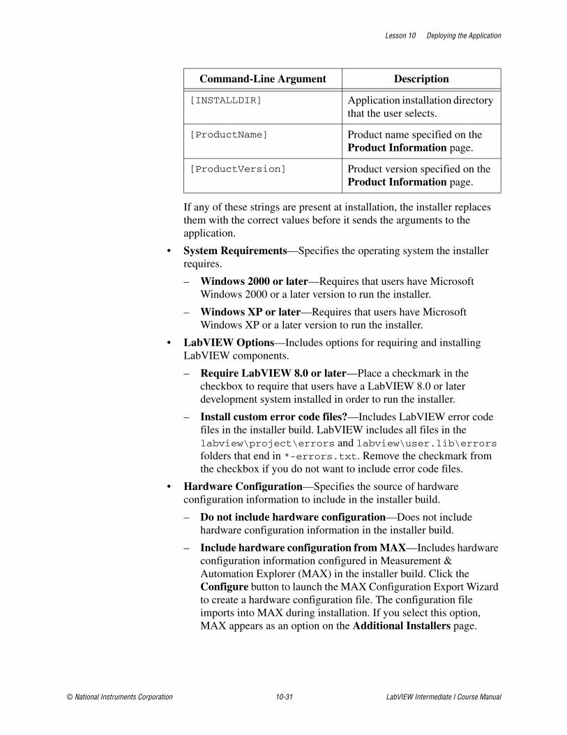
Lesson 10 Deploying the Application
© National Instruments Corporation 10-31 LabVIEW Intermediate I Course Manual
If any of these strings are present at installation, the installer replaces them with the correct values before it sends the arguments to the application.
• System Requirements—Specifies the operating system the installer requires.
– Windows 2000 or later—Requires that users have Microsoft Windows 2000 or a later version to run the installer.
– Windows XP or later—Requires that users have Microsoft Windows XP or a later version to run the installer.
• LabVIEW Options—Includes options for requiring and installing LabVIEW components.
– Require LabVIEW 8.0 or later—Place a checkmark in the checkbox to require that users have a LabVIEW 8.0 or later development system installed in order to run the installer.
– Install custom error code files?—Includes LabVIEW error code files in the installer build. LabVIEW includes all files in the labview\project\errors and labview\user.lib\errors folders that end in *-errors.txt. Remove the checkmark from the checkbox if you do not want to include error code files.
• Hardware Configuration—Specifies the source of hardware configuration information to include in the installer build.
– Do not include hardware configuration—Does not include hardware configuration information in the installer build.
– Include hardware configuration from MAX—Includes hardware configuration information configured in Measurement & Automation Explorer (MAX) in the installer build. Click the Configure button to launch the MAX Configuration Export Wizard to create a hardware configuration file. The configuration file imports into MAX during installation. If you select this option, MAX appears as an option on the Additional Installers page.
Command-Line Argument Description
[INSTALLDIR] Application installation directory that the user selects.
[ProductName] Product name specified on the Product Information page.
[ProductVersion] Product version specified on the Product Information page.

Lesson 10 Deploying the Application
LabVIEW Intermediate I Course Manual 10-32 ni.com
Exercise 10-3 Create an Installer
GoalUse LabVIEW to create a professional installer for your application.
ScenarioA professional application should always have an installer to deploy the application. Providing an installer improves the end user experience with the application.
DesignCreate an installer build specification for the executable you created.
Implementation1. Create an installer for the Theatre Light Controller.
2. Open TLC.lvproj.
❑ Right-click Build Specifications and select New»Installer from the shortcut menu to open the Installer Properties dialog box.
❑ On the Product Information page, specify a Build specification name, and Product name.
❑ Set the Installer destination to C:\Exercises\LabVIEW Intermediate I\Course Project\Builds\Installer.
❑ Select the Source Files page and verify that a folder that matches your project name exists under ProgramFilesFolder. If no folder exists for your project, add a folder and provide a meaningful name for the folder.
❑ In the Project View list, select the stand-alone application (EXE) build specification. Click the arrow to place the EXE build specification in the folder you created.
❑ Select the Shortcuts page to create a shortcut to the ProgramMenuFolder in Windows. Click the blue + button to open the Select Target File dialog box. Select the EXE for your project and click the OK button. Change the Name to Theatre Light Controller. This places the item in the Start»Programs menu.
❑ Select the Additional Installers page and verify that a checkmark appears in the checkbox for the LabVIEW Run-Time Engine installer.

Lesson 10 Deploying the Application
© National Instruments Corporation 10-33 LabVIEW Intermediate I Course Manual
❑ Click the OK button.
❑ Right-click the installer build specification and select Build from the shortcut menu.
Testing1. Navigate to the installer destination directory you specified and run the
installer. After the installer runs, verify the installation of the Theatre Light Controller.
End of Exercise 10-3

Lesson 10 Deploying the Application
LabVIEW Intermediate I Course Manual 10-34 ni.com
Summary• Verify that the relative file path handling is correct for built applications.
• Create an about dialog box for your application.
• Use the Icon page of the Application Properties dialog box to select the icon file (.ico) to use for a stand-alone application.
• Use the Application Builder tools to create a build specification for and build a stand-alone application (EXE).
• Use the Application Builder to build an installer for files in a LabVIEW project or for a stand-alone application you created with a build specification.

Lesson 10 Deploying the Application
© National Instruments Corporation 10-35 LabVIEW Intermediate I Course Manual
Notes

Lesson 10 Deploying the Application
LabVIEW Intermediate I Course Manual 10-36 ni.com
Notes
© National Instruments Corporation A-1 LabVIEW Intermediate I Course Manual
AIEEE Requirements Documents
This appendix describes the IEEE standards for software engineers and includes a requirements document for the Theater Light Control system that conforms to the IEEE 830 standard for requirements documents.
TopicsA. Institute of Electrical and Electronic Engineers (IEEE) Standards
B. IEEE Requirements Document
Appendix A IEEE Requirements Documents
LabVIEW Intermediate I Course Manual A-2 ni.com
A. Institute of Electrical and Electronic Engineers (IEEE) Standards
IEEE defined a number of standards for software engineering. IEEE Standard 730, first published in 1980, is a standard for software quality assurance plans. This standard serves as a foundation for several other IEEE standards and gives a brief description of the minimum requirements for a quality plan in the following areas:
• Purpose
• Reference documents
• Management
• Documentation
• Standards, practices, conventions, and metrics
• Reviews and audits
• Test
• Problem reporting and corrective action
• Tools, techniques, and methodologies
• Code control
• Media control
• Supplier control
• Records collection, maintenance, and retention
• Training
• Risk management
As with the ISO standards, IEEE 730 is fairly short. It does not dictate how to meet the requirements but requires documentation for these practices to a specified minimum level of detail.
In addition to IEEE 730, several other IEEE standards related to software engineering exist, including the following:
• IEEE 610—Defines standard software engineering terminology.
• IEEE 829—Establishes standards for software test documentation.
• IEEE 830—Explains the content of good software requirements specifications.
• IEEE 1074—Describes the activities performed as part of a software lifecycle without requiring a specific lifecycle model.
• IEEE 1298—Details the components of a software quality management system; similar to ISO 9001.
Appendix A IEEE Requirements Documents
© National Instruments Corporation A-3 LabVIEW Intermediate I Course Manual
Your projects may be required to meet some or all these standards. Even if you are not required to develop to any of these specifications, they can be helpful in developing your own requirements, specifications, and quality plans.
B. IEEE Requirements DocumentThe following requirements document for the Theater Light Controller system conforms to the IEEE-830 specification for requirements documents.
Start of Requirements Document
Section 1: IntroductionThis section provides an overview of the software requirements document.
PurposeThe purpose of this document is to provide a detailed, precise, and easy to understand set of software requirements. Software developers use this document as a reference to design, implement, and test the software. This document serves as a basis to begin implementation of the software.
ScopeThe scope of this document is to describe the software requirements for the Theatre Light Control Software. The deliverables for the Theatre Light Control Software will consist of the software system and software documentation.
Definitions, Acronyms, and AbbreviationsThe requirements document uses the following definitions, acronyms, and abbreviations.
• API—Application Program Interface.
• Byte—Unit of memory storage in the computer to store one character of information.
• Channel—The most basic element of the Theatre Light Control Software. Each channel corresponds to a physical light.
• Channel Array—Allocated memory that stores information regarding the channels. Portions of this array are displayed to the user on the front panel.
• Channel Counter—Variable that can be used to iterate through channels.
Appendix A IEEE Requirements Documents
LabVIEW Intermediate I Course Manual A-4 ni.com
Requirements Document Continued
• Color—Attribute of the channel that defines the color of the channel as a combination of red, green, and blue.
• Cue—A cue contains any number of independent channels with timing attributes for the channels.
• Cue List—Contains a list of all the recorded cues.
• Fade Time— Cue timing attribute that defines the time it takes, in multiples of one second, before a channel reaches its particular intensity and color.
• Follow Time— A cue timing attribute that defines the amount of time to wait, in multiples of one second, before the cue finishes.
• Intensity—Attribute of the channel that defines the intensity of the physical light.
• Light—A standard theatre light that has the ability to vary in intensity from 0% to 100% and change in color with a combination of red, green, and blue.
• Megabyte—1 Mb equals 220 bytes.
• Pan—Theatre light motion control that provides horizontal movement
• Theatre Lighting Hardware Device—Hardware interface to the theatre lights that controls the power, switching, and drive to the theatre lights.
• Tilt—Theatre light motion control that provides vertical movement
• Wait Time—A cue timing attribute that defines the amount of time to wait, in multiples of one second, before the cue fires.
ReferencesIEEE Recommended Practice for Software Requirements Specifications, IEEE Std. 830-1998.
Document OverviewThis document contains three sections. The first section is an introduction and overview of the requirements document. The second section provides an overall description of the software that will be produced. The third section addresses the specific requirements of the Theatre Light Control Software.
Section 2: Overall DescriptionThis section describes the general issues that can affect the software requirements of the product. This section does not provide detailed information on the requirements for the product.
Appendix A IEEE Requirements Documents
© National Instruments Corporation A-5 LabVIEW Intermediate I Course Manual
Requirements Document Continued
Product PerspectiveThe Theatre Light Control Software will perform as part of a theatre lighting system as described by the specifications provided by ABC Theatre Lighting Inc. The Theatre Light Control Software will provide the necessary control for the theatre lighting system to operate.
The Theatre Light Control Software is an independent and entirely self-contained control system that interfaces with the local theatre lighting hardware device. The theatre lighting device controls the color and intensity of the physical lights.
Product FunctionsThe Theatre Light Control Software will perform the following functions:
• Initialize
• Record
• Load
• Save
• Play
• Move Cue Up
• Move Cue Down
• Select Cue
• Delete
• Stop
• Close
User CharacteristicsThe users of the Theatre Light Control Software will have a deep understanding of how theatre light systems operate. Also, the users will be able to understand how to install and integrate the Theatre Light Control Software into their system.
ConstraintsThe following are general design constraints for the Theatre Light Control Software:
• The Theatre Light Control Software will be written in LabVIEW.
• The software must be able to control at least 16 channels.
• All minimum user-defined software times are one second.
Appendix A IEEE Requirements Documents
LabVIEW Intermediate I Course Manual A-6 ni.com
Requirements Document Continued
• The minimum wait time and follow time is zero seconds.
• The minimum fade time is one second.
• The software must conform to the guidelines outlined in the customer specification.
Assumptions and DependenciesThe Theatre Lighting Hardware Device will provide a standardized API that the Theatre Light Control Software can interface to.
Apportioning of RequirementsMany theatre lighting hardware devices provide for lights that have motor control to move the light around the stage. The Theatre Light Control Software shall provide for the ability to easily implement channel pan and tilt in a future version of the software. The Theatre Light Control Software will only interface to theatre lighting hardware devices that do not contain motor control capability for this version of the software.
Section 3: Specific RequirementsThis section describes the specific requirements in detail. The software should be developed to meet these requirements and tested to verify that the system satisfies the requirements.
External Interface RequirementsThis section provides details about the inputs and outputs to the software.
User InterfacesThe main user interface shall clearly display to the user the current status of the channel and recorded cues. The following figure shows the main user interface.
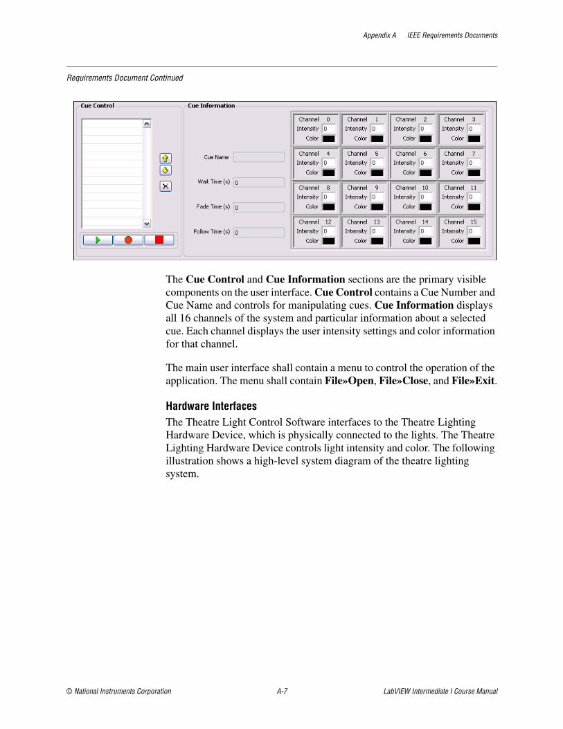
Appendix A IEEE Requirements Documents
© National Instruments Corporation A-7 LabVIEW Intermediate I Course Manual
Requirements Document Continued
The Cue Control and Cue Information sections are the primary visible components on the user interface. Cue Control contains a Cue Number and Cue Name and controls for manipulating cues. Cue Information displays all 16 channels of the system and particular information about a selected cue. Each channel displays the user intensity settings and color information for that channel.
The main user interface shall contain a menu to control the operation of the application. The menu shall contain File»Open, File»Close, and File»Exit.
Hardware InterfacesThe Theatre Light Control Software interfaces to the Theatre Lighting Hardware Device, which is physically connected to the lights. The Theatre Lighting Hardware Device controls light intensity and color. The following illustration shows a high-level system diagram of the theatre lighting system.
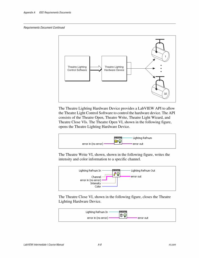
Appendix A IEEE Requirements Documents
LabVIEW Intermediate I Course Manual A-8 ni.com
Requirements Document Continued
The Theatre Lighting Hardware Device provides a LabVIEW API to allow the Theatre Light Control Software to control the hardware device. The API consists of the Theatre Open, Theatre Write, Theatre Light Wizard, and Theatre Close VIs. The Theatre Open VI, shown in the following figure, opens the Theatre Lighting Hardware Device.
The Theatre Write VI, shown, shown in the following figure, writes the intensity and color information to a specific channel.
The Theatre Close VI, shown in the following figure, closes the Theatre Lighting Hardware Device.
Theatre LightingControl Software
Theatre LightingHardware Device
1
32
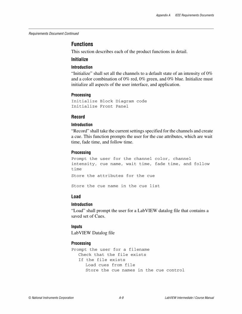
Appendix A IEEE Requirements Documents
© National Instruments Corporation A-9 LabVIEW Intermediate I Course Manual
Requirements Document Continued
FunctionsThis section describes each of the product functions in detail.
Initialize
Introduction“Initialize” shall set all the channels to a default state of an intensity of 0% and a color combination of 0% red, 0% green, and 0% blue. Initialize must initialize all aspects of the user interface, and application.
ProcessingInitialize Block Diagram codeInitialize Front Panel
Record
Introduction“Record” shall take the current settings specified for the channels and create a cue. This function prompts the user for the cue attributes, which are wait time, fade time, and follow time.
ProcessingPrompt the user for the channel color, channel intensity, cue name, wait time, fade time, and follow time
Store the attributes for the cue
Store the cue name in the cue list
Load
Introduction“Load” shall prompt the user for a LabVIEW datalog file that contains a saved set of Cues.
InputsLabVIEW Datalog file
ProcessingPrompt the user for a filename
Check that the file existsIf the file exists
Load cues from fileStore the cue names in the cue control
Appendix A IEEE Requirements Documents
LabVIEW Intermediate I Course Manual A-10 ni.com
Requirements Document Continued
Save
Introduction“Save Cues” shall store all attributes that relate to the cues in a LabVIEW datalog file.
ProcessingPrompt the user for a filenameCheck that file existsIf the file exists
Prompt the user that file existsSuspend processing
Save all recorded cues in memory
OutputsLabVIEW Datalog file Prompts
Play
Introduction“Play” shall start at the top of the Cue List and execute the cue in real time. This function updates the front panel channel array by displaying what the Theatre Lighting Hardware Device is being commanded to do. The information displayed to the user on the front panel will correspond to the information that is being communicated to the Theatre Lighting Hardware Device using the LabVIEW API.
ProcessingDisable the following controls: Record, Play, Up, Down, DeleteRepeat the following for each cue:
Wait for the number of seconds specified by wait timeFade the channels in the cue to the desired level within the specified number of fade time secondsWait for the number of seconds specified by the follow time
Enable the following controls: Record, Play, Up, Down, Delete
OutputsTheatre Lighting Hardware Device Display
Move Cue Up
Introduction“Move Cue Up” shall move the currently selected Cue up one level.
Appendix A IEEE Requirements Documents
© National Instruments Corporation A-11 LabVIEW Intermediate I Course Manual
Requirements Document Continued
ProcessingCheck if currently selected cue is the first cue in the listIf the selected cue is not the first cue in the list
Swap Selected Cue with Selected Cue - 1
Move Cue Down
Introduction“Move Cue Down” shall move the currently selected Cue down one level.
ProcessingCheck if currently selected cue is the last cue in the listIf the selected cue is not the last cue in the list
Swap Selected Cue with Selected Cue + 1
Select Cue
Introduction“Select Cue” shall display the Cue Name, Fade Time, Wait Time, and Follow Time for the Cue in the Cue Information display when a Cue is selected in the Cue List. This function also enables the Move Cue Up, Move Cue Down, and Delete functions to operate as expected.
ProcessingGet Cue Values for Selected CueUpdate Front Panel Channels
Delete
Introduction“Delete” shall delete a cue and all information regarding the cue that is stored in memory.
ProcessingDelete Selected CueUpdate Cue List
Stop
Introduction"Stop" shall cause any playing cue to stop when the button is clicked.
ProcessingSend a stop message to stop playing cues
Appendix A IEEE Requirements Documents
LabVIEW Intermediate I Course Manual A-12 ni.com
Requirements Document Continued
Close
Introduction“Exit” shall close all open references and cleanly stop the application. This function also initializes all channels to an intensity of 0% with a color combination of 0% red, 0% green, and 0% blue.
ProcessingShutdown all modulesShutdown all open references
OutputsTheatre Lighting Hardware Device Channel array
Performance Requirements• The software must respond to user commands within 100 ms.
• The software must not use 100% of the CPU time.
Design ConstraintsThe software will be tested with 32 channels.
Software System AttributesThe Theatre Light Control Software will contain certain quality attributes built into the working product specified in this document.
ReliabilityThe Theatre Light Control Software will have been thoroughly tested at time of delivery so that computational errors will not occur.
AvailabilityThe Theatre Light Control Software will not require any operating service intervals for preventive maintenance.
SecurityBecause of the nature of the Theatre Light Control Software, no data or files will be encrypted. Therefore, no security controls will be built into the application.
MaintainabilityThe LabVIEW Automation Company will maintain the Theatre Light Control Software and provide software documentation.
Appendix A IEEE Requirements Documents
© National Instruments Corporation A-13 LabVIEW Intermediate I Course Manual
Requirements Document Continued
Logical Database RequirementsThere do not exist any specific requirements for a database because a database is not required for the application.
Other RequirementsNo other requirements exist for the application.
End of Requirements Document

© National Instruments Corporation B-1 LabVIEW Intermediate I Course Manual
BAdditional Information and Resources
This appendix contains additional information about National Instruments technical support options and LabVIEW resources.
National Instruments Technical Support OptionsVisit the following sections of the National Instruments Web site at ni.com for technical support and professional services.
• Support—Online technical support resources at ni.com/support include the following:
– Self-Help Resources—For answers and solutions, visit the award-winning National Instruments Web site for software drivers and updates, a searchable KnowledgeBase, product manuals, step-by-step troubleshooting wizards, thousands of example programs, tutorials, application notes, instrument drivers, and so on.
– Free Technical Support—All registered users receive free Basic Service, which includes access to hundreds of Application Engineers worldwide in the NI Developer Exchange at ni.com/exchange. National Instruments Application Engineers make sure every question receives an answer.
For information about other technical support options in your area, visit ni.com/services or contact your local office at ni.com/contact.
• System Integration—If you have time constraints, limited in-house technical resources, or other project challenges, National Instruments Alliance Partner members can help. The NI Alliance Partners joins system integrators, consultants, and hardware vendors to provide comprehensive service and expertise to customers. The program ensures qualified, specialized assistance for application and system development. To learn more, call your local NI office or visit ni.com/alliance.
If you searched ni.com and could not find the answers you need, contact your local office or NI corporate headquarters. Phone numbers for our worldwide offices are listed at the front of this manual. You also can visit the Worldwide Offices section of ni.com/niglobal to access the branch office Web sites, which provide up-to-date contact information, support phone numbers, email addresses, and current events.
Appendix B Additional Information and Resources
LabVIEW Intermediate I Course Manual B-2 ni.com
Other National Instruments Training CoursesNational Instruments offers several training courses for LabVIEW users. These courses continue the training you received here and expand it to other areas. Visit ni.com/training to purchase course materials or sign up for instructor-led, hands-on courses at locations around the world.
National Instruments CertificationEarning an NI certification acknowledges your expertise in working with NI products and technologies. The measurement and automation industry, your employer, clients, and peers recognize your NI certification credential as a symbol of the skills and knowledge you have gained through experience. areas. Visit ni.com/training for more information about the NI certification program.
LabVIEW ResourcesThis section describes how you can receive more information regarding LabVIEW.
LabVIEW PublicationsThe following publications offer more information about LabVIEW.
LabVIEW Technical Resource (LTR) NewsletterSubscribe to LabVIEW Technical Resource to discover tips and techniques for developing LabVIEW applications. This quarterly publication offers detailed technical information for novice users and advanced users. In addition, every issue contains a disk of LabVIEW VIs and utilities that implement methods covered in that issue. To order the LabVIEW Technical Resource, contact LTR publishing at (214) 706-0587 or visit www.ltrpub.com.
LabVIEW BooksMany books have been written about LabVIEW programming and applications. The National Instruments Web site contains a list of all the LabVIEW books and links to places to purchase these books.
info-labview Listserveinfo-labview is an email group of users from around the world who discuss LabVIEW issues. The list members can answer questions about building LabVIEW systems for particular applications, where to get instrument drivers or help with a device, and problems that appear.

Appendix B Additional Information and Resources
© National Instruments Corporation B-3 LabVIEW Intermediate I Course Manual
To subscribe to info-labview, send email to:
To subscribe to the digest version of info-labview, send email to:
To unsubscribe to info-labview, send email to:
To post a message to subscribers, send email to:
To send other administrative messages to the info-labview list manager, send email to:
You might also want to search previous email messages at:
www.searchVIEW.net
The info-labview web page is available at www.info-labview.org

© National Instruments Corporation G-1 LabVIEW Intermediate I Course Manual
Glossary
Numbers
1D One-dimensional.
2D Two-dimensional.
A
A Amperes.
absolute path File or directory path that describes the location relative to the top level of the file system.
active window Window that is currently set to accept user input, usually the frontmost window. The title bar of an active window is highlighted. Make a window active by clicking it or by selecting it from the Windows menu.
application software Application created using the LabVIEW Development System and executed in the LabVIEW Run-Time System environment.
array Ordered, indexed list of data elements of the same type.
array shell Front panel object that houses an array. An array shell consists of an index display, a data object window, and an optional label. It can accept various data types.
artificial data dependency
Condition in a dataflow programming language in which the arrival of data, rather than its value, triggers execution of a node.
ASCII American Standard Code for Information Interchange.
auto-indexing Capability of loop structures to disassemble and assemble arrays at their borders. As an array enters a loop with auto-indexing enabled, the loop automatically disassembles it extracting scalars from ID arrays, ID arrays extracted from 2D arrays, and so on. Loops assemble data into arrays as data exit the loop in the reverse order.
autoscaling Ability of scales to adjust to the range of plotted values. On graph scales, autoscaling determines maximum and minimum scale values.
Glossary
LabVIEW Intermediate I Course Manual G-2 ni.com
B
black box testing Form of testing where a module is tested without knowing how the module is implemented. The module is treated as if it were a black box that you cannot look inside. Instead, you generate tests to verify the module behaves the way it is supposed to according to the requirements specification.
block diagram Pictorial description or representation of a program or algorithm. The block diagram consists of executable icons called nodes and wires that carry data between the nodes. The block diagram is the source code for the VI. The block diagram resides in the block diagram window of the VI.
Boolean controls and indicators
Front panel objects to manipulate and display Boolean (TRUE or FALSE) data.
buffer Temporary storage for acquired or generated data.
Bundle node Function that creates clusters from various types of elements.
C
Capability Maturity Model (CMM)
Model for judging the maturity of the processes of an organization and for identifying the key practices required to increase the maturity of these processes. The Software CMM (SW-CMM) is a de facto standard for assessing and improving software processes. Through the SW-CMM, the Software Engineering Institute and software development community have put in place an effective means for modeling, defining, and measuring the maturity of the processes software professionals use.
caption label Label on a front panel object used to name the object in the user interface. You can translate this label to other languages without affecting the block diagram source code. See also Name Label.
case One subdiagram of a Case structure.
Case structure Conditional branching control structure, that executes one of its subdiagrams based on the input to the Case structure. It is the combination of the IF, THEN, ELSE, and CASE statements in control flow languages.
checkbox Small square box in a dialog box you can select or clear. Checkboxes generally are associated with multiple options that you can set. You can select more than one checkbox.
CIN See Code Interface Node (CIN).

Glossary
© National Instruments Corporation G-3 LabVIEW Intermediate I Course Manual
cluster A set of ordered, unindexed data elements of any data type, including numeric, Boolean, string, array, or cluster. The elements must be all controls or all indicators.
cluster shell Front panel object that contains the elements of a cluster.
COCOMO Estimation COnstructive COst MOdel. A formula-based estimation method for converting software size estimates to estimated development time.
code and fix model Lifecycle model that involves developing code with little or no planning and fixing problems as they arise.
Code Interface Node (CIN)
Special block diagram node through which you can link text-based code to a VI.
coercion Automatic conversion LabVIEW performs to change the numeric representation of a data element.
coercion dot Appears on a block diagram node to alert you that you have wired data of two different numeric data types together. Also appears when you wire any data type to a variant data type.
cohesion How well a single module focuses on a single goal.
Color Copying tool Copies colors for pasting with the Coloring tool.
Coloring tool Tool to set foreground and background colors.
compile Process that converts high-level code to machine-executable code. LabVIEW compiles VIs automatically before they run for the first time after you create or edit alteration.
connector Part of the VI or function node that contains input and output terminals. Data pass to and from the node through a connector.
connector pane Region in the upper right corner of a front panel or block diagram window that displays the VI terminal pattern. It defines the inputs and outputs you can wire to a VI.
constant See universal constant and user-defined constant.
Context Help window Window that displays basic information about LabVIEW objects when you move the cursor over each object. Objects with context help information include VIs, functions, constants, structures, palettes, properties, methods, events, and dialog box components.
control Front panel object for entering data to a VI interactively or to a subVI programmatically, such as a knob, push button, or dial.
Glossary
LabVIEW Intermediate I Course Manual G-4 ni.com
control flow Programming system in which the sequential order of instructions determines execution order. Most text-based programming languages are control flow languages.
conversion Changing the type of a data element.
count terminal Terminal of a For Loop whose value determines the number of times the For Loop executes its subdiagram.
coupling Connection that is established from one module to another.
current VI VI whose front panel, block diagram, or Icon Editor is the active window.
D
D Delta; Difference. ∆x denotes the value by which x changes from one index to the next.
DAQ See data acquisition.
data acquisition DAQ. Process of acquiring data, typically from A/D or digital input plug-in devices.
data dependency Condition in a dataflow programming language in which a node cannot execute until it receives data from another node. See also artificial data dependency.
data encapsulation See information hiding.
data flow Programming system that consists of executable nodes that execute only when they receive all required input data and produce output automatically when they execute. LabVIEW is a dataflow system.
data storage formats Arrangement and representation of data stored in memory.
data type Format for information. In LabVIEW, acceptable data types for most VIs and functions are numeric, array, string, Boolean, path, refnum, enumeration, waveform, and cluster.
data type descriptor Code that identifies data types; used in data storage and representation.
datalog file File that stores data as a sequence of records of a single, arbitrary data type that you specify when you create the file. Although all the records in a datalog file must be a single type, that type can be complex. For example, you can specify that each record is a cluster that contains a string, a number, and an array.

Glossary
© National Instruments Corporation G-5 LabVIEW Intermediate I Course Manual
datalogging Generally, to acquire data and simultaneously store it in a disk file. LabVIEW file I/O VIs and functions can log data.
default Preset value. Many VI inputs use a default value if you do not specify a value.
default input Default value of a front panel control.
design patterns Techniques that have proved themselves useful for developing software. Design patterns typically evolve through the efforts of many developers and are fine-tuned for simplicity, maintainability, and readability.
device Instrument or controller that is addressable as a single entity and controls or monitors real-world I/O points. A device is often connected to the host computer through some type of communication network or can be a plug-in device.
For data acquisition (DAQ) applications, a DAQ device is inside your computer or attached directly to the parallel port of your computer. Plug-in boards, PCMCIA cards, and devices such as the DAQPad-1200, which connects to your computer's parallel port, are all examples of DAQ devices. SCXI modules are distinct from devices, with the exception of the SCXI-1200, which is a hybrid.
dialog box Window that appears when an application needs further information to carry out a command.
dimension Size and structure of an array.
directory Structure for organizing files into convenient groups. A directory is like an address that shows the location of files. A directory can contain files or subdirectories of files.
DLL Dynamic Link Library.
driver Software that controls a specific hardware device, such as a DAQ device.
Glossary
LabVIEW Intermediate I Course Manual G-6 ni.com
E
empty array Array that has zero elements but has a defined data type. For example, an array that has a numeric control in its data display window but has no defined values for any element is an empty numeric array.
error in Error structure that enters a VI.
error message Indication of a software or hardware malfunction or of an unacceptable data entry attempt.
error out The error structure that leaves a VI.
error structure Consists of a Boolean status indicator, a numeric code indicator, and a string source indicator.
event Condition or state of an analog or digital signal.
event driven programming
Method of programming whereby the program waits on an event to occur before executing one or more functions.
F
file refnum See refnum.
Flat Sequence structure Program control structure that executes its subdiagrams in numeric order. Use this structure to force nodes that are not data dependent to execute in the order you want. The Flat Sequence structure displays all the frames simultaneously and executes the frames from left to right until the last frame executes.
For Loop Iterative loop structure that executes its subdiagram a set number of times. Equivalent to text-based code: For i = 0 to n – 1, do....
frame Subdiagram of a Flat or Stacked Sequence structure.
free label Label on the front panel or block diagram that does not belong to any other object.
front panel Interactive user interface of a VI. Front panel appearance imitates physical instruments, such as oscilloscopes and multimeters.
function Built-in execution element, comparable to an operator, function, or statement in a text-based programming language.
Glossary
© National Instruments Corporation G-7 LabVIEW Intermediate I Course Manual
functional global variable
A VI containing a single-iteration While Loop with an uninitialized shift register. A functional global variable is similar to a global variable, but it does not make extra copies of data in memory. Functional global variables also can expand beyond simple read and write functionality.
G
General Purpose Interface Bus
GPIB—synonymous with HP-IB. The standard bus used for controlling electronic instruments with a computer. Also called IEEE 488 bus because it is defined by ANSI/IEEE Standards 488-1978, 488.1-1987, and 488.2-1992.
global variable Accesses and passes data among several VIs on a block diagram.
GPIB See General Purpose Interface Bus.
H
heuristic A recognized usability principle.
Hierarchy window Window that graphically displays the hierarchy of VIs and subVIs.
I
I/O Input/Output. The transfer of data to or from a computer system involving communications channels, operator input devices, and/or data acquisition and control interfaces.
icon Graphical representation of a node on a block diagram.
Icon Editor Interface similar to that of a graphics program for creating VI icons.
IEEE Institute for Electrical and Electronic Engineers.
indicator Front panel object that displays output, such as a graph or LED.
information hiding Preventing or limiting other components from accessing data items in a module except through some predetermined method.
inplace The condition in which two or more terminals, such as error I/O terminals or shift registers, use the same memory space.
inplace execution Ability of a VI or function to reuse memory instead of allocating more.

Glossary
LabVIEW Intermediate I Course Manual G-8 ni.com
integration testing Integration testing assures that individual components work together correctly. Such testing may uncover, for example, a misunderstanding of the interface between modules.
ISA Industry Standard Architecture.
iteration terminal Terminal of a For Loop or While Loop that contains the current number of completed iterations.
L
label Text object used to name or describe objects or regions on the front panel or block diagram.
Labeling tool Tool to create labels and enter text into text windows.
LabVIEW Laboratory Virtual Instrument Engineering Workbench. LabVIEW is a graphical programming language that uses icons instead of lines of text to create programs.
LED Light-emitting diode.
library See VI library.
lifecycle model Model for software development, including steps to follow from the initial concept through the release, maintenance, and upgrading of the software.
listbox Box within a dialog box that lists all available choices for a command. For example, a list of filenames on a disk.
LLB VI Library.
local variable Variable that enables you to read or write to one of the controls or indicators on the front panel of a VI.
M
memory buffer See buffer.
menu bar Horizontal bar that lists the names of the main menus of an application. The menu bar appears below the title bar of a window. Each application has a menu bar that is distinct for that application, although some menus and commands are common to many applications.
modular programming Type of programming that uses interchangeable computer routines.
Glossary
© National Instruments Corporation G-9 LabVIEW Intermediate I Course Manual
multithreaded application
Application that runs several different threads of execution independently. On a multiple processor computer, the different threads might be running on different processors simultaneously.
N
Name Label Label of a front panel object used to name the object and as distinguish it from other objects. The label also appears on the block diagram terminal, local variables, and property nodes that are part of the object. See also caption label.
node Program execution element. Nodes are analogous to statements, operators, functions, and subroutines in text-based programming languages. On a block diagram, nodes include functions, structures, and subVIs.
non-displayable characters
ASCII characters that cannot be displayed, such as null, backspace, tab, and so on.
numeric controlsand indicators
Front panel objects to manipulate and display numeric data.
O
object Generic term for any item on the front panel or block diagram, including controls, indicators, nodes, wires, and imported pictures.
operator Person who initiates and monitors the operation of a process.
P
palette Display of icons that represent possible options.
panel window VI window that contains the front panel, the toolbar, and the icon and connector panes.
pixel Smallest unit of a digitized picture.
polling Method of sequentially observing each I/O point or user interface control to determine if it is ready to receive data or request computer action.
Property Node Sets or finds the properties of a VI or application.
Glossary
LabVIEW Intermediate I Course Manual G-10 ni.com
prototype Simple, quick implementation of a particular task to demonstrate that the design has the potential to work. The prototype usually has missing features and might have design flaws. In general, prototypes should be thrown away, and the feature should be reimplemented for the final version.
pseudocode Simplified language-independent representation of programming code.
pull-down menus Menus accessed from a menu bar. Pull-down menu items are usually general in nature.
R
race condition Occurs when two or more pieces of code that execute in parallel change the value of the same shared resource, typically a global or local variable.
real-time Pertaining to the performance of a computation during the actual time that the related physical process transpires so results of the computation can be used in guiding the physical process.
refactor Redesign software to make it more readable and maintainable so that the cost of change does not increase over time. Refactoring changes the internal structure of a VI to make it more readable and maintainable, without changing its observable behavior.
refnum Reference number. An identifier that LabVIEW associates with a file you open. Use the refnum to indicate that you want a function or VI to perform an operation on the open file.
representation Subtype of the numeric data type, of which there are 8-, 16-, and 32-bit signed and unsigned integers, as well as single-, double-, and extended-precision floating-point numbers.
ring control Special numeric control that associates 32-bit integers, starting at 0 and increasing sequentially, with a series of text labels or graphics.
S
scalar Number that a point on a scale can represent. A single value as opposed to an array. Scalar Booleans and clusters are explicitly singular instances of their respective data types.
sequence structure See Flat Sequence structure or Stacked Sequence structure.
Glossary
© National Instruments Corporation G-11 LabVIEW Intermediate I Course Manual
shared library A file containing executable program modules that any number of different programs can use to perform some function. Shared libraries are useful when you want to share the functionality of the VIs you build with other developers.
shift register Optional mechanism in loop structures to pass the value of a variable from one iteration of a loop to a subsequent iteration. Shift registers are similar to static variables in text-based programming languages.
shortcut menu Menu accessed by right-clicking an object. Menu items pertain to that object specifically.
software configuration management (SCM)
Mechanism for controlling changes to source code, documents, and other material that make up a product. During software development, source code control is a form of configuration management. Changes occur only through the source code control mechanism. It also is common to implement release configuration management to ensure you can rebuild a particular release of software, if necessary. Configuration management implies archival development of tools, source code, and so on.
Software Engineering Institute (SEI)
Federally funded research and development center to study software engineering technology. The SEI is located at Carnegie Mellon University and is sponsored by the Defense Advanced Research Projects Agency. Refer to the Software Engineering Institute Web site at www.sei.cmu.edu for more information about the institute.
source lines of code Measure of the number of lines of code that make up a text-based project. It is used in some organizations to measure the complexity and cost of a project. How the lines are counted depends on the organization. For example, some organizations do not count blank lines and comment lines. Some count C lines, and some count only the final assembly language lines.
spaghetti code Code that contains program constructs that do not form an easy to understand, logical flow.
specifications document Document that lists the individual tasks that define the function of the application that is produced by the customer.
spiral model Lifecycle model that emphasizes risk management through a series of iterations in which risks are identified, evaluated, and resolved.
Stacked Sequence structure
Program control structure that executes its subdiagrams in numeric order. Use this structure to force nodes that are not data dependent to execute in the order you want. The Stacked Sequence structure displays each frame so you see only one frame at a time and executes the frames in order until the last frame executes.
Glossary
LabVIEW Intermediate I Course Manual G-12 ni.com
string Representation of a value as text.
string controls and indicators
Front panel objects to manipulate and display text.
structure Program control element, such as a Flat Sequence structure, Stacked Sequence structure, Case structure, For Loop, or While Loop.
stub VI Nonfunctional prototype of a subVI. A stub VI has inputs and outputs, but is incomplete. Use stub VIs during early planning stages of an application design as a place holder for future VI development.
subdiagram Block diagram within the border of a structure.
subVI VI used on the block diagram of another VI. Comparable to a subroutine.
system testing System testing begins after integration testing is complete. System testing assures that all the individual components function correctly together and constitute a product that meets the intended requirements. This stage often uncovers performance, resource usage, and other problems.
T
terminal Object or region on a node through which data pass.
tip strip Small yellow text banners that identify the terminal name and make it easier to identify terminals for wiring.
top-level VI VI at the top of the VI hierarchy. This term distinguishes the VI from its subVIs.
tunnel Data entry or exit terminal on a structure.
type definition Master copy of a custom object that several VIs can use.
type descriptor See data type descriptor.
U
unit testing Testing only a single component of a system in isolation from the rest of the system. Unit testing occurs before the module is incorporated into the rest of the system.
universal constant Uneditable block diagram object that emits a particular ASCII character or standard numeric constant, for example, π.
Glossary
© National Instruments Corporation G-13 LabVIEW Intermediate I Course Manual
user-defined constant Block diagram object that emits a value you set.
UUT Unit under test.
V
Variant Data type that includes the control or indicator name, information about the data type from which you converted, and the data itself, which allows LabVIEW to correctly convert the variant data type to the data type you want.
VI See virtual instrument (VI).
VI library Special file that contains a collection of related VIs for a specific use.
VI Server Mechanism for controlling VIs and LabVIEW applications programmatically, locally and remotely.
virtual instrument (VI) Program in LabVIEW that models the appearance and function of a physical instrument.
W
waterfall model Lifecycle model that consists of several non-overlapping stages, beginning with the software concept and continuing through testing and maintenance.
While Loop Loop structure that repeats a section of code until a condition is met.
white box testing Unlike black box testing, white box testing creates tests that take into account the particular implementation of the module. For example, use white box testing to verify all the paths of execution of the module have been exercised.
wire Data path between nodes.
wire bend Point where two wire segments join.
wire branch Section of wire that contains all the wire segments from junction to junction, terminal to junction, or terminal to terminal if there are no junctions between.
wire junction Point where three or more wire segments join.
wire segment Single horizontal or vertical piece of wire.
wire stubs Truncated wires that appear next to unwired terminals when you move the Wiring tool over a VI or function node.

© National Instruments Corporation I-1 LabVIEW Intermediate I Course Manual
Index
Symbols.ini files
reading and writing, 6-32
Aabout dialog box, 10-3abstract components
data abstraction, 2-17drawing
dataflow diagrams, 2-27flow charts, 2-25
procedural abstraction, 2-17alpha testing, 7-55application
analyzing an, 2-1build specifications, 10-13building, 10-1
caveats and recommendations, 10-5designing an, 4-1documenting, 9-1error handling strategies, 4-76evaluating performance, 8-1hierarchical architecture, 4-41implementing
code, 6-1, 10-2scalable architecture, 6-7user interface, 5-1
menu items, 3-5support files
icons, 10-17test plan, 7-1user interface, 3-2
Application Builder, 10-13application documentation, 9-3arrays, 4-55
Bbeta testing, 7-55block diagram
comments, 6-28left-to-right layouts, 6-28positioning, 6-27sizing, 6-27style considerations, 6-27variant data, 6-10wiring techniques, 6-27
Boolean controls and indicatorscompared to ring and enumerated type
controls, 5-3boundary conditions, testing, 7-4build specifications, 10-13building
applications, 10-13shared libraries, 10-13stand-alone applications, 10-13
Ccaptions, 3-13certification (NI resources), vii, B-2checklist
code implementation, 6-65customer communication, 2-7data structures, 4-56error handling strategy, 4-79front panel style, 3-19hierarchical architecture, 4-42performance issues, 8-23requirements document, 2-8scalable architecture, 6-11specifications content, 2-4test plan, 7-5testing strategy, 7-9user interface-based data, 5-7
classic controls and indicators, 3-15clusters, 4-55
error, 4-77code
developing, 6-27documenting, 6-28
Index
LabVIEW Intermediate I Course Manual I-2 ni.com
implementing, 6-1, 6-27, 10-2about dialog box, 10-3checklist, 6-65relative file path handling, 10-2
performance, 8-2reviews, 7-2self-documenting, 6-31verification, 7-2
code and fix model, 1-5code reviews, 7-2coercion dots, avoiding, 8-16cohesion, 2-24color
high-color controls and indicators, 3-15low-color controls and indicators, 3-15style guidelines, 3-2
color style guidelines, 3-2comments on the block diagram, 6-28communication
checklist, 2-7customer expectations, 2-6programmer expectations, 2-6
Configuration File VIscreating configuration files, 6-33format, 6-33reading and writing .ini files, 6-32
configuration filesconfiguration settings files, 6-33creating, 6-32Windows configuration settings file
formats, 6-33configuration management, 6-2
change control, 6-4retrieving old versions of files, 6-3source control, 6-2tracking changes, 6-3
configuration tests, 7-53connector pane
implementing, 5-15recommended patterns, 5-15style guidelines, 5-15
constants, eliminating, 6-32containers
subpanel controls, 3-8tab controls, 3-7
controlscaptions, 3-12classic, 3-15colors, 3-2custom controls, 3-3default values, 3-14descriptions, 9-6dialog, 3-15enumerated type controls, 5-2fonts, 3-2graphics, 3-3high-color, 3-15keyboard navigation, 3-14labels, 3-12layout, 3-4low-color, 3-15modern, 3-15naming, 3-12paths, 3-13performance considerations, 8-18positioning, 3-11ranges, 3-14ring, 5-2ring controls, 5-2sizing, 3-11strings, 3-13tab, 3-7text, 3-2
conventions used in the manual, xcoupling, 2-24course
conventions used in the manual, xdescription, viiigoals, ixproject
overview, 1-11terminal objective, 1-11
requirements for getting started, viiisoftware installation, ix
creatingrevision history, 9-4

Index
© National Instruments Corporation I-3 LabVIEW Intermediate I Course Manual
custom controlsguidelines, 3-3
customer communicationcustomer expectations, 2-6programmer expectations, 2-6
customizingrun-time shortcut menus, 3-6
Ddata abstraction, 2-17data acquisition system design example,
2-18, 2-22data encapsulation. See information hidingdata structures
arrays, 4-55checklist, 4-56choosing, 4-55clusters, 4-55scalars, 4-55user interface-based, 5-2
data types, choosing, 5-2dataflow diagrams, 2-27DataSocket, documenting, 6-30decorations
for visual grouping of objects, 3-6decorations, for visual grouping of objects,
3-6default values for controls, 3-14dependencies, 4-45design patterns
comparing, 4-38documenting, 9-3execution timing, 6-36initializing, 6-7master/slave, 4-8producer/consumer (data), 4-10producer/consumer (events), 4-26queued message handler, 4-5software control timing, 6-38state machine, 4-4timing, 6-36user interface event handler, 4-25
design techniques
defining requirements for application, 2-16
front panel prototyping, 3-16developing VIs
tracking development, 9-4development models, 1-4
See also design techniquescode and fix model, 1-5lifecycle models, 1-4modified waterfall model, 1-7prototyping for clarification, 1-8spiral model, 1-9waterfall model, 1-5
diagnostic tools (NI resources), B-1dialog box, about, 10-3dialog boxes
controls, 3-15indicators, 3-15labels, 3-15ring controls, 5-2
directoriesnaming, 6-34, 6-35style considerations, 6-34VI search path, 6-36
documentation, NI resources, B-1documenting
applications, 9-1code, 6-28DataSocket, 6-30design patterns, 9-3developing documentation, 9-2Express VIs, 6-29help files, 9-9implementing documentation, 9-1overview, 9-2user documentation, 9-2
documenting applicationscontrols, 9-5developing documentation, 9-2documenting front panels, 9-5help files, 9-9indicators, 9-5LabVIEW features, 9-2
Index
LabVIEW Intermediate I Course Manual I-4 ni.com
library of VIs, 9-2organizing, 9-2user documentation, 9-2, 9-3VIs, 9-5
documenting VIscontrols, 9-6descriptions, 9-5indicators, 9-6revision history, 9-4
drag and drop, 3-10creating an operation, 3-11
drawingabstracted components, 2-25dataflow diagrams, 2-27flow charts, 2-25
drivers (NI resources), B-1
EEmbedded Project Manager, 4-43enumerated type controls
compared to Boolean and ring controls, 5-3
error handlingchecking for errors, 4-77checklist, 4-79error codes, 4-78
custom, 4-78implementing, 6-76strategies, 4-76
implementing, 6-76tests, 7-4
errorsclusters, 4-77codes, 4-77I/O, 4-77methods to handle, 4-77
evaluating specifications, 2-2events
front panel locking, 4-19examples (NI resources), B-1execution
speed, 8-17Express VIs, documenting, 6-29
Ffeature creep, preventing, 2-3file
structure, 6-34file I/O
Configuration File VIs, 6-32ini files, 6-32reading .ini files with Configuration File
VIs, 6-32writing .ini files with Configuration File
VIs, 6-32file management
change control, 6-4previous versions of files, 6-3tracking changes, 6-3
filenamesdirectories, 6-34, 6-36LLBs, 6-36VI libraries, 6-34VIs, 6-34, 6-36
flow charts, 2-25font style guidelines, 3-2front panel
captions, 3-13colors, 3-2custom controls, 3-3default values, 3-14documenting, 9-5graphics, 3-3keyboard navigation, 3-14loading in subpanel controls, 3-8locking when using events, 4-19overlapping objects, 3-7positioning, 3-11prototyping, 3-16ranges, 3-14sizing, 3-11
front panelscolors, 3-2default values, 3-14design, 3-2dialog controls, 3-15enumerated type controls, 5-2
Index
© National Instruments Corporation I-5 LabVIEW Intermediate I Course Manual
examples, 3-17fonts, 3-2graphics, 3-3keyboard navigation, 3-14labels, 3-12layout, 3-4localization, 3-18palettes, 3-15paths, 3-13positioning, 3-11prototyping, 3-16ranges, 3-14ring controls, 5-2sizing, 3-11strings, 3-13style checklist, 3-19style considerations, 3-2text, 3-2transparent, 3-10
functional global variable, 4-61using for timing, 4-62, 6-39
functional global variablesguidelines, 6-65
functional specification (definition), 2-2functional tests, 7-3
boundary conditions, 7-4hand checking, 7-4
functionality, testing, 7-54
Gglobal variables
functional global variables, 4-61timing, 4-62
graphics, 3-3guidelines, 3-3
Hhelp files, 9-9
creating, 9-9creating (guidelines), 9-9linking to VIs, 9-9
help, technical support, B-1
heuristics, usability, 7-55hierarchical architecture, 4-41
checklist, 4-42cohesion, 2-24coupling, 2-24
hierarchical organization of filesdirectories, 6-34, 6-35folders, 6-34naming
directories, 6-34VI libraries, 6-34VIs, 6-34
naming directories, 6-36naming LLBs, 6-36naming VIs, 6-36
hierarchy, 4-41history
See also revision historyHistory window
documenting VIs, 9-2
II/O
effect on VI performance, 8-18error, 4-77
iconsart glossary, 5-12custom application icons, 10-17intuitive icons, 5-13style guidelines, 5-12
IEEE (Institute of Electrical and Electronic Engineers) standards, A-2
indicatorscaptions, 3-12classic, 3-15colors, 3-2custom controls, 3-3descriptions, 9-6dialog, 3-15fonts, 3-2graphics, 3-3high-color, 3-15keyboard navigation, 3-14

Index
LabVIEW Intermediate I Course Manual I-6 ni.com
labels, 3-12layout, 3-4low-color, 3-15modern, 3-15paths, 3-13positioning, 3-11sizing, 3-11strings, 3-13style considerations, 3-2tab, 3-7text, 3-2
information hiding, 4-60global variables, 4-60
initializingdesign patterns, 6-7feedback nodes, 6-9initialization state, 6-8shift registers, 6-9using single frame Sequence structure,
6-7installer
building an, 10-23installers, 10-13installing the course software, ixInstitute of Electrical and Electronic
Engineers (IEEE) standards, A-2instrument drivers (NI resources), B-1integration testing, 7-6
big-bang, 7-7bottom-up, 7-8sandwich, 7-8top-down, 7-7
Kkeyboard navigation, 3-14KnowledgeBase, B-1
Llabeling
captions, 3-13labels
block diagram documentation, 6-28
controls, 3-12dialog box, 3-15font usage, 3-2indicators, 3-12keyboard navigation, 3-12
LabVIEW projects, 4-42viewing dependencies, 4-45
left-to-right layouts, 6-28libraries
See also LLBlifecycle models, 1-4
code and fix model, 1-5modified waterfall model, 1-7prototyping, 1-8spiral model, 1-9waterfall model, 1-5
lines of code. See source lines of code (SLOCs) metric
LLBsnaming, 6-36
load tests, 7-54localization guidelines, 3-18locking
front panels with events, 4-19
Mmaintainable
modules, 6-60VIs, creating, 1-3
master/slave design pattern, 4-8memory
allocation, 8-14developing for, 6-65reallocation buffers, 8-14variant data, 6-10
menushandling selections, 3-5ring controls, 5-2selection handling, 3-5static menus, 3-4
modelsSee also development modelSee also prototyping

Index
© National Instruments Corporation I-7 LabVIEW Intermediate I Course Manual
modified waterfall model, 1-7
Nnaming
controls, 3-12directories, 6-34, 6-36guidelines for VIs, 6-36LLB, 6-36VI libraries, 6-34VIs, 6-34
National Instruments support and services, B-1
NI, Certification, vii, B-2non-functional specification (definition), 2-2
Oobjects
captions on front panel, 3-13overlapping on front panel, 3-7
organizing documentation, 9-2overlapping front panel objects, 3-7
Ppalettes, 3-15paths
See also relative file path handlingcompared to strings, 3-13front panels, 3-13
performancechecklist, 8-23coercion and memory, 8-16developing for, 6-65evaluating, 8-1improving, 8-2memory allocation, 8-14memory reallocation buffers, 8-14problems, 8-13
fixing, 8-14identifying, 8-13
tests, 7-54VI Analyzer Toolkit, 8-5VI execution speed, 8-17
defer panel updates, 8-20input/output, 8-18screen display, 8-18
VI Metrics tool, 8-2VI Performance Profiler, 8-13
picturesring controls, 5-2
positioningblock diagrams, 6-27front panels, 3-11
positioning, front panels, 3-11Print dialog box
printing documentation, 9-2procedural abstraction, 2-17producer/consumer (data) design pattern,
4-10producer/consumer (events) design pattern,
4-26functional global variables, 4-61queues, 4-27synchronization, 4-27variant data type, 6-10
Profile Performance and Memory windowusing, 8-13
programming examples (NI resources), B-1project
See also applicationanalysis, 2-1data structures, 4-55requirements, determining, 2-16scalable architecture, 4-2software design, 4-1user interface design, 3-1
Project Explorer window, 4-43project libraries, 4-46
organizing, 4-52using sublibraries, 4-48
projectsSee also LabVIEW projects
prototypingSee also design techniquesSee also prototypingdevelopment model, 1-8
Index
LabVIEW Intermediate I Course Manual I-8 ni.com
front panel prototyping, 3-16LabVIEW prototyping methods, 1-8
pull-down menus on front panel, 5-2
Qquality control
change control, 6-4code reviews, 7-2configuration management, 6-2
retrieving old versions of files, 6-3IEEE, A-2retrieving old versions of files, 6-3tracking changes, 6-3
queued message handler design pattern, 4-5requirements, 4-6
Rranges of values for controls, 3-14readable VIs, creating, 1-3relative file path handling, 10-2reliability testing, 7-54requirements
abstracting components, 2-17checklist, 2-8determining, 2-16developing, 2-8
requirements for getting started, viiireviews
code, 7-2revision history
creating, 9-4numbers, 9-4
ring controls, 5-2compared to Boolean and enumerated
type controls, 5-3rings, front panel, 5-2risk management
See spiral modelrun-time shortcut menus
customizing, 3-6
Sscalable architecture
checklist, 6-11choosing a, 4-2comparing, 4-38implementing, 6-7initializing, 6-7master/slave design pattern, 4-8producer/consumer (data) design pattern,
4-10producer/consumer (events) design
pattern, 4-26queued message handler design pattern,
4-5state machine design pattern, 4-4timing, 6-36user interface event handler design
pattern, 4-25scalable VIs, creating, 1-2scalable, modules, 6-60scalar data, 4-55
enumerated type controls, 5-2numeric, 5-3ring controls, 5-2
scroll bar controls, 3-9shared libraries, 10-13sizing
front panels, 3-11software (NI resources), B-1software development map, 1-1software installation, course, ixsoftware lifecycles, 1-4software quality standards
Institute of Electrical and Electronic Engineers (IEEE), A-2
source code control toolsprevious versions of files, 6-3
source controlchange control, 6-4quality control considerations, 6-2tracking changes, 6-3
source distributions, 10-13source lines of code (SLOCs) metric, 8-2

Index
© National Instruments Corporation I-9 LabVIEW Intermediate I Course Manual
specificationschecklist, 2-4evaluating, 2-2functional, 2-2non-functional, 2-2
speed at run timeoptimizing, 8-17
spiral model, 1-9split pane container, 3-9splitter bars, 3-9stand-alone applications, 10-13state machine
design pattern, 4-4infrastructure, 4-4
static menus, 3-4application items, 3-5separators, 3-5user items, 3-4
stress tests, 7-54strings
compared to paths, 3-13strings, front panels, 3-13stub VIs, 7-7style guidelines
block diagram, 6-27sizing, 6-27speed optimization, 6-65wiring techniques, 6-27
connector panes, 5-15documentation, 6-28front panels
colors, 3-2default values, 3-14fonts, 3-2graphics, 3-3keyboard navigation, 3-14labels, 3-12layout, 3-4paths, 3-13ranges, 3-14sizing and positioning, 3-11strings, 3-13text, 3-2
hierarchical organization of filesdirectories, 6-34folders, 6-34naming VIs, VI libraries, and
directories, 6-34icons, 5-12
subpanel controls, 3-8subVI library
documenting, 9-2successful development
overview, 1-1practices, 1-4
support, technical, B-1system
controls and indicators, 3-15system testing, 7-53
Ttab controls, 3-7technical support, B-1test
alpha, 7-55beta, 7-55
testingboundary conditions, 7-4checklist, 7-5, 7-9configuration, 7-53error, 7-4functionality, 7-3, 7-54guidelines
integration testing, 7-6system testing, 7-53unit testing, 7-3usability testing, 7-57
hand checking, 7-4implementing, 7-1individual VIs, 7-2, 7-3integration, 7-6
big-bang, 7-7bottom-up, 7-8sandwich, 7-8top-down, 7-7
performance, 7-54
Index
LabVIEW Intermediate I Course Manual I-10 ni.com
reliability, 7-54stress/load, 7-54system, 7-53usability, 7-55, 7-57
testing guidelinesintegration testing, 7-6system testing, 7-53
textring controls, 5-2
text style guidelines, 3-2timing
design patterns, 6-36execution, 6-36functional global variable, 4-62, 6-39software control, 6-38
Get Date/Time in Seconds, 6-39tracking changes, 6-3tracking development, 9-4training (NI resources), B-2transparent front panels, 3-10tree controls, 3-8troubleshooting (NI resources), B-1
Uunit test, 7-2
plan, 7-2usability
engineering techniques, 7-57heuristics, 7-55testing, 7-55, 7-57
user documentationSee documenting applications
user documentation. See documenting applications
user interfaceSee also front panelsdata structures
arrays, 5-5checklist, 5-7clusters, 5-6
designing an, 3-1event handler, 4-25implementing, 5-1
scalar data, numerics, 5-3
Vvariant data
handling, 6-10Variant data type, producer/consumer
(events) design pattern, 6-10VI Analyzer Toolkit, 8-5VI libraries
documenting, 9-2VI Metrics tool, 8-2VI Performance Profiler, 8-13viewing
dependencies in projects, 4-45VIs
hierarchical organization, 6-34linking to help files, 9-5naming, 6-34
Wwaterfall model, 1-5
modified, 1-7Web resources, B-1wiring techniques, 6-27
Zzip files, 10-13
Course Evaluation
Course _______________________________________________________________________________________
Location _____________________________________________________________________________________
Instructor _________________________________________ Date ____________________________________
Student Information (optional)Name ________________________________________________________________________________________
Company _________________________________________ Phone ___________________________________
InstructorPlease evaluate the instructor by checking the appropriate circle. Unsatisfactory Poor Satisfactory Good Excellent
Instructor’s ability to communicate course concepts ❍ ❍ ❍ ❍ ❍
Instructor’s knowledge of the subject matter ❍ ❍ ❍ ❍ ❍
Instructor’s presentation skills ❍ ❍ ❍ ❍ ❍
Instructor’s sensitivity to class needs ❍ ❍ ❍ ❍ ❍
Instructor’s preparation for the class ❍ ❍ ❍ ❍ ❍
CourseTraining facility quality ❍ ❍ ❍ ❍ ❍
Training equipment quality ❍ ❍ ❍ ❍ ❍
Was the hardware set up correctly? ❍ Yes ❍ No
The course length was ❍ Too long ❍ Just right ❍ Too short
The detail of topics covered in the course was ❍ Too much ❍ Just right ❍ Not enough
The course material was clear and easy to follow. ❍ Yes ❍ No ❍ Sometimes
Did the course cover material as advertised? ❍ Yes ❍ No
I had the skills or knowledge I needed to attend this course. ❍ Yes ❍ No If no, how could you have been
better prepared for the course? ____________________________________________________________________
_____________________________________________________________________________________________
What were the strong points of the course? __________________________________________________________
_____________________________________________________________________________________________
What topics would you add to the course? ___________________________________________________________
_____________________________________________________________________________________________
What part(s) of the course need to be condensed or removed? ____________________________________________
_____________________________________________________________________________________________
What needs to be added to the course to make it better? ________________________________________________
_____________________________________________________________________________________________
How did you benefit from taking this course? ________________________________________________________
_____________________________________________________________________________________________
Are there others at your company who have training needs? Please list. ____________________________________
_____________________________________________________________________________________________
_____________________________________________________________________________________________
Do you have other training needs that we could assist you with? _________________________________________
_____________________________________________________________________________________________
How did you hear about this course? ❍ NI Web site ❍ NI Sales Representative ❍ Mailing ❍ Co-worker
❍ Other _____________________________________________________________________________________