Laboratory / Pilot Plant Equipment D-12 Flotation Machine ...Operation and Maintenance Manual pg. 5...
42
Laboratory / Pilot Plant Equipment D-12 Flotation Machine (VFD) Legend, Inc. www.Lmine.com (775)786-3003 e: [email protected]
Transcript of Laboratory / Pilot Plant Equipment D-12 Flotation Machine ...Operation and Maintenance Manual pg. 5...

Laboratory / Pilot Plant Equipment D-12 Flotation Machine (VFD)
Legend, Inc. www.Lmine.com(775)786-3003 e: [email protected]

1. General1.1 About this Manual 1.2 Transport and Storage 1.3 Equipment Specification 1.4 Customer Service
2. Description2.1 Product and Warning Signs 2.2 Applications 2.3 Design 2.4 General Arrangement 2.5 Certificates
3. Health and Safety3.1 General
4. Description of Operation4.1 Preparation for Operation 4.2 Flotation Operation
5. Control System
6. Installation6.1 General 6.2 Foundation Requirements 6.3 Motor and Drive
7. Operation Instructions7.1 Starting and Stopping the Machine 7.2 Alternate Operations
8. Care / Maintenance & Alternative Setups8.1 Safety Measures 8.2 Suspended Mechanism Spring Adjustment 8.3 Impeller, Diffuser, and Fluidizer Replacement 8.4 Converting Machine to Agitator 8.5 Converting Machine to Attrition Scrubber 8.6 Bearing Replacement
9. Spare Parts9.1 Recommended Stock of Spare Parts 9.2 Spare Parts Drawing
Legend, Inc. www.Lmine.com (775)786-3003 e: [email protected]

D12 Flotation Machine (VFD)
Operation and Maintenance Manual pg. 3
1. General
1.1 About this Manual
This manual is a part of the equipment to which it relates. It is written for the use of installers, commissioning engineers, operators and maintainers. It should be kept for the life of the equipment and, in case of re-sale, passed on to any subsequent purchaser.
Information contained in this manual is specific to the equipment and is correct at the date of publication. As improvements are continually being made, Metso Minerals reserves the right to make alterations to the equipment design and specification, without giving prior notice. Any amendments issued by Metso Minerals should be promptly inserted into this manual. © 2013 — Metso Minerals Industries Inc. The contents of this manual must not be reproduced without the prior written permission of Metso Minerals Industries Inc.
1.2 Transport and Storage
The machine is supplied with a cast iron base complete with motor. All bearings are pre-lubricated before shipment.
When receiving the machine check that all items listed have been supplied and have not been damaged in transit. Loose items such as tanks, vanning plaque, etc., are usually shipped in one or more separate containers.
If damage has occurred, or any items are missing, immediately file a report with the carrier making the delivery. Also, submit a written report to Metso Minerals detailing the damage and/or missing items, as soon as possible. Include photos to further explain the issue.
1.2.2 Handling and Lifting
When lifting the unit, make sure to only lift it using the cast iron base or with the supplied lifting eyelet securely affixed to the drive guard stud.
The weight for the complete unit is found under section 1.3.
The unit is bolted to bottom of pallet when initially shipped.
WARNING
MAKE SURE THAT ALL SLINGS, SHACKLES, ETC. USED ARE OF ADEQUATE LOAD CARRYING CAPACITY FOR THE UNIT TO BE LIFTED. CHECK THAT ALL LIFTING EQUIPMENT CERTIFICATES ARE CURRENT.
Legend, Inc. www.Lmine.com (775)786-3003 e: [email protected]

D12 Flotation Machine (VFD)
Operation and Maintenance Manual pg. 4
1.3 Equipment Specification Machine weight: 87 kg 192 lb Total weight: 122.5 kg 270 lb Machine Dimensions (L x W x H): 1016 mm x 610mm x 991mm 40in x 24in x 39in Total Crate: 1219mm x 610mm x 1042mm 48in x 24in x 41in Machine Speed (rpm/min): (Legacy 60 Hz) 800—3200 (Legacy 50 Hz) 660—2650 (VFD) 580—3500 Motor: (Legacy) USA 1/2 HP, 1800 rpm, single-phase 60 Hz, 115 / 230 Volt TEFC, ball-bearing motor (Legacy) Non -USA 1/2 HP, 1425 rpm, single-phase 50 Hz, 110 / 220 Volt
TEFC, ball-bearing motor (VFD) 1/2HP, 3500 rpm, three-phase 60 Hz, 208-230 / 460 Volt, 56 Frame TEFC, ball-bearing motor
Legend, Inc. www.Lmine.com (775)786-3003 e: [email protected]

D12 Flotation Machine (VFD)
Operation and Maintenance Manual pg. 5
1.4 Customer Service For information regarding service & repair of Metso laboratory machines, please contact the closest Metso office. To receive information on where to find the closest office, contact one of the headquarters listed below: Metso Minerals Industries, Inc. 350 Railroad Street Danville PA 17821-2046 Tel: (+1) 570 275 3050 USA Fax: (+1) 570 275 6789 Email: [email protected] Please provide the following information: 1 - Model and machine size 2 - Serial number 3 - Approximate date of purchase 4 - Request details, visible errors and more.
Legend, Inc. www.Lmine.com (775)786-3003 e: [email protected]

D12 Flotation Machine (VFD)
Operation and Maintenance Manual pg. 6
2. Description 2.1 Product and Warning Signs 2.1.1 Product Signs All product signs attached to the machine are shown below.
A machine sign containing information as above is affixed to the machine base. Equipment delivered with a motor has a machine sign with CE-mark.
Legend, Inc. www.Lmine.com (775)786-3003 e: [email protected]

D12 Flotation Machine (VFD)
Operation and Maintenance Manual pg. 7
2.1.2 Warning and Caution Signs
These signs are fitted to the guard at the lifting hooks. The hooks are only meant for lifting the guards!
Due to the risk of high noise levels and danger of dust from the activation chamber you should wear ear and eye protection.
Crush hazard. Do not insert tools or other foreign objects into crushing chamber when the machine is operating. Depending on type of material, it could be a potential risk of material being thrown out of the chamber. Do not look into the chamber when the machine is operating.
Crush hazard. Keep hands clear from moving parts!
This sign is fitted to the belt guard. The guard should always be fitted when the machine is in operation. If the guard is to be removed, check that the motor is disconnected from the mains or that the main switch is turned off and locked so that the motor cannot be started inadvertently. The guard must always be refitted before the motor is started.
Legend, Inc. www.Lmine.com (775)786-3003 e: [email protected]

D12 Flotation Machine (VFD)
Operation and Maintenance Manual pg. 8
2.2 Applications This equipment is designed to test flotation scenarios. This machine will allow small batch tests to determine air required, possible mixtures, and concentrations to produce the best separation efficiency of material in the laboratory and small pilot plants. This information can then be used to possibly enhance a larger scale operation. 2.3 Design 2.3.1 General These machines can also be used as agitators or attrition scrubbers with the addition of an optional kit. The Model D-12 machine is used for 250, 500, 1000, and 2000 gram tests. One 1000 gram acrylic tank is furnished with each machine. The other tanks (250, 500, 1000, and 2000 gram) are stainless steel. Each machine consists of the following: cast iron base, aluminum supporting column and arm; suspended type mechanism with totally enclosed anti-friction spindle bearing, stainless steel shaft, stainless steel standpipe with air control valve, removable polyurethane diffuser and polyurethane receded disk impeller, drive guard, rubber base mat, (Motor See Section 1.3), belt drive, white enamel vanning plaque, Hydrion pH indicator, set of sample reagents, small hand magnet, and acrylic plastic, recirculation collar (fluidizer). A switch mounting box & toggle switch (legacy models), variable frequency drive & emergency stop (VFD models), and cable with plug are furnished with each machine for connecting electrical power to the machine. For both legacy and VFD model machines we offer a stainless steel attrition scrubbing kit (consisting of: lower spindle bearing cap, one-piece double attrition propeller, and tank with splash cover) for attrition scrubbing tests; and an agitation kit (consisting of lower spindle bearing cap, single agitator propeller, a glass tank) for agitation tests. Additional 250, 500, 1000, and 2000 gram stainless steel tanks and 1000 gram acrylic tanks are available if required. The suspended type mechanism is spring-balanced and is easily raised or lowered with the hand crank on the side of the machine. The mechanism can be locked in any vertical position with the spring-loaded locking pin on the side opposite the hand crank. This pin must be pulled out and held when operating the hand crank. When the desired position is reached, release the pin, and it will lock the mechanism in place.
This sign, attached to the machine, indicates that the machine requires periodic greasing.
Legend, Inc. www.Lmine.com (775)786-3003 e: [email protected]

D12 Flotation Machine (VFD)
Operation and Maintenance Manual pg. 9
Legend, Inc. www.Lmine.com (775)786-3003 e: [email protected]

D12 Flotation Machine (VFD)
Operation and Maintenance Manual pg. 10
2.3.2 Noise Level The noise level (Lpa) for the machine is measured to 60.7dBA when idling; the noise level for the machine is dependent on the material being mixed.
Legend, Inc. www.Lmine.com (775)786-3003 e: [email protected]

D12 Flotation Machine (VFD)
Operation and Maintenance Manual pg. 11
2.4 General Arrangement
Variable Frequency Drive Spindle Bearing Housing Motor Mounting Plate Pinion Locking Knob Emergency Stop Spindle Bearing Support Standpipe Tank Base Pad Base
Legend, Inc. www.Lmine.com (775)786-3003 e: [email protected]

D12 Flotation Machine (VFD)
Operation and Maintenance Manual pg. 12
Lifting Eyelet & Hex Nut Drive Guard Drive Guard Stud Pulleys & Belt Impeller Shaft Spindle Bearing Cap Bearing & Oil Seal Set Screw (both sides) Motor Bearing & Oil Seal Air Petcock Hand Crank Hood Impeller
Legend, Inc. www.Lmine.com (775)786-3003 e: [email protected]

D12 Flotation Machine (VFD)
Operation and Maintenance Manual pg. 13
2.5 Certificates
Legend, Inc. www.Lmine.com (775)786-3003 e: [email protected]

D12 Flotation Machine (VFD)
Operation and Maintenance Manual pg. 14
3. Health and Safety 3.1 General
HEALTH AND SAFETY STATEMENT 3.1.1 Warnings and Cautions For the purpose of definition in this manual, a WARNING gives information, which if ignored, could lead to serious injury of personnel. A CAUTION gives information, which if ignored, could lead to serious damage to the machine or associated equipment.
WARNING
CAUTION
DO TAKE TIME TO ENSURE THAT YOUR SAFETY AND THAT OF OTHERS IS NOT PUT AT RISK. FAILURE TO OBSERVE CERTAIN ELEMENTARY SAFETY PRECAUTIONS MAY RESULT IN PERSONAL INJURY OR DAMAGE TO THIS EQUIPMENT. THE SAFETY INFORMATION IN THIS AND OTHER SECTIONS IS INTENDED TO ENCOURAGE A SAFETY CONSCIOUS APPROACH WHILE OPERATING AND CARRYING OUT MAINTENANCE.
PARAGRAPHS WHICH PURELY PROVIDE A WARNING NOTICE ARE BOXED AND HIGHLIGHTED IN THIS STYLE.
PARAGRAPHS WHICH PURELY PROVIDE A CAUTIONARY NOTICE ARE BOXED AND HIGHLIGHTED IN THIS STYLE.
Legend, Inc. www.Lmine.com (775)786-3003 e: [email protected]

D12 Flotation Machine (VFD)
Operation and Maintenance Manual pg. 15
3.1.2 Training It is strongly recommended that all customers' production, maintenance personnel, and site visitors are made fully aware of the potential dangers of this equipment. If any doubt exists, please contact Metso for advice. Hazardous areas: These are in the areas of the flywheels and V-belt
drive. Under normal operating conditions these areas MUST be enclosed by safety guards.
Other hazardous areas are the agitation area; for practical reasons, these areas are not enclosed by covers.
For your own safety, you should NEVER put hands or fingers into the agitation area without first ensuring that the power is disconnected and secured.
Lifting the machine: Make sure that ALL slings, shackles, etc. are of adequate load carrying capacity. When lifting the
complete unit it has to be moved by the cast iron base or by supplied lifting eyelet affixed to the drive guard stud. Use caution; observe that the weight distribution will not be equal.
Operating the machine: Ensure that ALL safety covers and guards are in position and securely fitted. This equipment must
not be modified and/or used for duties, processes, materials, etc., other than that receiving approval from Metso Minerals. Failure to adhere to this warning may result in equipment damage and/or unsafe working conditions, resulting in serious personal injury.
Servicing the machine: SWITCH OFF and ISOLATE the electrical supply
to the machine motor and allow rotating parts to come to rest before carrying out any maintenance or adjustments.
Do NOT substitute replacement parts without the
approval of Metso Minerals. Parts substitution can result in equipment damage and unsafe working conditions resulting, in serious personal injury.
FOR YOUR OWN PERSONAL SAFETY, READ AND TAKE NOTE OF THE FOLLOWING:
Legend, Inc. www.Lmine.com (775)786-3003 e: [email protected]

D12 Flotation Machine (VFD)
Operation and Maintenance Manual pg. 16
4. Description Of Operation 4.1 Preparation for Operation While there is little chance of contamination when using the flotation machine, the machine should be thoroughly cleaned between tests to avoid this possibility. The suspended type mechanism and separate tanks lend themselves to easy and complete cleaning. If ample precautions are taken, the weighed products from the test should check close to the original weight of the sample introduced into the cell. Should the weights not check the trouble should be investigated. In many cases, certain ores and products are partially soluble or may contain a slight moisture content which accounts for such variations. All operations prior to and after the flotation step should be handled with equal care, if an accurate balance is to be obtained. Drying, for example, should be watched carefully to insure complete moisture removal and avoid overheating. Preparations of the various test products after drying and before obtaining chemical analysis, should be carefully performed. This phase of the test program is sometimes underestimated or neglected.
Legend, Inc. www.Lmine.com (775)786-3003 e: [email protected]

D12 Flotation Machine (VFD)
Operation and Maintenance Manual pg. 17
D12 Lab Flotation Machine Quick Start Guide
Keypad Layout with Main Speed Potentiometer
1.) Plug D12 into power supply. If the Variable Frequency Drive (VFD) does not turn on, make sure the emergency stop button is reset by twisting it counter clockwise.
2.) Flip the VFD toggle switch (if equipped) to ON. The display will blink “Stop”.
3.) Keep clear of moving parts. Press to start the D12.
4.) Set the desired speed using the Potentiometer. Turn clockwise to increase RPM.
5.) Press again to stop the D12 under normal operating conditions.
6.) Should the emergency stop be activated while the D12 is running, the display will blink “-LU-“. To resume normal operation, twist the emergency stop button clockwise to reset it. The display will now blink “LU-r”. Next, press to reset the VFD. Now, the display will flash “Stop”.
Proceed to Step 3 to resume operation.
Note: The VFD screen will take a few moments to discharge once turned off or unplugged. This is normal.
Legend, Inc. www.Lmine.com (775)786-3003 e: [email protected]

D12 Flotation Machine (VFD)
Operation and Maintenance Manual pg. 18
4.2 Flotation Operation The Model D-12 machine is usually set up for the 2000 gram tests and must be changed in order to perform the 250 to 1000 gram tests. To change the Model D-12, replace impeller and diffuser on machine with the impeller and diffuser shipped loose (see Section 8: CARE / MAINTENANCE & ALTERNATE SETUP). The following paragraphs give a brief outline of several important factors having a marked influence on flotation technique and results. When performing tests, it is necessary to use the utmost care in keeping accurate records of all conditions present during the test which might influence the results or be of importance in interpreting the test data. If proper care is exercised, duplication of results is assured in an operating plant. SPEED ADJUSTMENT Legacy Speed of the machine is adjusted by turning the knob located directly above the motor and connected to the variable speed sheave. To increase speed, turn the knob counterclockwise. To decrease speed, turn the knob clockwise. Adjust speed only when machine is running. VFD Speed of the machine is adjusted by turning the potentiometer located directly on the Variable Frequency Drive. To increase speed, turn the knob clockwise. To decrease speed, turn the knob counterclockwise. The nominal speed required for each test is a factor within the control of the operator who, by observation, will quickly determine the proper speed for each operation. Machines furnished with tachometers are ideal for obtaining nominal speed during specific tests and can be used in setting speeds for comparative tests. Normal operating speeds are as follows: 250, 500, or 1000 gram tests: Approximately 1300 rpm 2000 gram tests: Approximately 1200 rpm HEIGHT ADJUSTMENT To adjust the height of the machine, pull the pinion locking knob out while simultaneously rotating the hand crank. Counter clockwise raises; clockwise lowers. Release the pinion locking knob when the desired height is reached. AERATION CONTROL The machine induces its own air so it is not necessary to have an external air source. However, pressurized air can be added if desired.
Legend, Inc. www.Lmine.com (775)786-3003 e: [email protected]

D12 Flotation Machine (VFD)
Operation and Maintenance Manual pg. 19
The air valve at the top of the standpipe is used for aeration control during the aeration and flotation operation. The valve is closed during conditioning and opened during the aeration and flotation period. USE OF PLASTIC RECIRCULATION COLLAR (FLUIDIZER) FOR FLOTATION The holes in the diffuser on the lower end of the standpipe permit recirculation of pulp to the impeller, enhancing the aerating and mixing characteristics of the flotation machine. However, recirculation of low density pulp from the upper zone of the cell into the denser zone at the bottom of the cell is often desirable. This is particularly true for coarse or de-slimed feeds, as the fluidizing action created by recirculation of pulp from the upper zone of the cell minimizes stratification of sands, improving flotation results. The fluidizer furnished with each machine is used for upper-zone recirculation. Refer to Section 8 (CARE / MAINTENANCE & ALTERNATE SETUPS) for installation of the fluidizer. After the fluidizer is installed, it may be left on the machine. When the fluidizer is not needed for a test, it can be raised out of position and hung on the air valve using a small piece of wire. This makes it unnecessary to dismantle the machine each time the fluidizer is needed or not needed for a test. Also, comparative tests with and without the fluidizer can be conveniently performed or the principle advantage of upper recirculation can be readily determined. OBTAINING THE SAMPLE AND GRINDING The sample should be representative of the anticipated feed for commercial flotation since all laboratory results will pertain to the flotation characteristics of the test sample. A discrepancy in the material can lead to erroneous conclusions, thus effecting the interpretation of the results. If drying is necessary, great care should be exercised to avoid unnecessarily high temperatures or prolonged heat. The same method should be used for grinding as will be used in practice. That is, if wet grinding is to be used, that method should be used in testing. Another important factor is water; water from the same source, and at about the same temperature should be used in testing as will be used in the mill. While these points may be considered as refinements, it will be found that they will be of help in arriving at correct conclusions. The use of mine water should be avoided as much as possible, due to probable acidity and soluble salt content. FINENESS OF GRIND The degree to which a certain ore must be ground to secure a satisfactory extraction of a mineral depends upon the physical characteristics of the ore. Generally, the largest particle which can be floated commercially is minus 20-mesh, although a much coarser particle size may be circulated while floating the usually finer mineral values. Naturally, the coarsest grind in which the mineral is liberated from the gangue should be determined, and thus a savings in power and grinding media will result.
Legend, Inc. www.Lmine.com (775)786-3003 e: [email protected]
D12 Flotation Machine (VFD)
Operation and Maintenance Manual pg. 20
A better extraction will be made if the ore is not over-ground. Tests should be made first at a coarse mesh, saving as much as possible at this size; the tailings should then be reground for further tests to liberate the remaining values. It pays to remove the mineral as soon as liberated. KIND AND QUANTITY OF REAGENTS It is impossible to specify the reagents which will give good results on any ore. Many articles are published on reagents used on certain ores, but these can only be used as a guide; each ore has certain characteristics that can only be determined by test work. Refer to a reagent handbook which describes most of the common flotation reagents available, their uses, and their characteristics. Literature available from reagent manufacturers is also helpful. METHOD OF FEEDING The quantity of reagent required is usually very small. It may, however, be found that the laboratory machine requires slightly more reagent than will be used in practice. The previously referenced handbook lists the usual quantities of specific reagents used in flotation. Liquid reagents should be introduced in the flotation cell drop by drop using an eye dropper. Water soluble dry reagents, made up as a l-percent solution, should be added with a graduate or pipette. All reagent quantities should be recorded as part of the test data. It is usually desirable to temporarily close the air valve while adding reagents, enabling a more thorough mixing of the reagent and pulp to be attained. CONDITIONING Conditioning is the time which the reagents must be in intimate association with the pulp in order to exert their full effect--prior to flotation. In practice, the reagents may be added to the ball mill (or at some intermediate point in the mill circuit) thus allowing sufficient time for the reagent to take effect. In other instances, conditioning tanks with mechanical agitators are required for a longer conditioning period. The length of time (usually in the range of 5 to 15 minutes) can usually be determined in a laboratory machine by observing the time required after the addition of reagents and until a good froth appears. During this time, air may or may not be admitted through the air valve and the machine may be operated at a lower speed. During the conditioning period, it is sometimes advisable to have a pulp dilution of about 50-percent solids. After the reagents are thoroughly mixed, additional water is added and the air is controlled by the test engineer as required. The conditioning time should be recorded as a vital part of the test procedure. HYDROGEN ION CONCENTRATION (pH) The pH scale is used to denote the acidity or alkalinity of the ore pulp. In general, the best flotation conditions exist when the pulp is slightly alkaline; in some cases it may be undesirable or uneconomical to use an alkaline circuit. Likewise, there are certain minerals that float much more readily in an acidic solution of pulp. In this instance, an acid circuit should be used. The pH indication should be recorded during the test. When flotation is to
Legend, Inc. www.Lmine.com (775)786-3003 e: [email protected]

D12 Flotation Machine (VFD)
Operation and Maintenance Manual pg. 21
be conducted in an alkaline circuit, the reagent (usually soda ash or lime) is added to the batch grinding mill. DILUTION Dilution is the ratio of water to solids in the pulp. Thus, 4:1 would indicate four parts water to one part dry solids, by weight. This can also be expressed as 20-percent solids. Coarse flotation will require a higher pulp density than will be necessary if the ore is finely ground. For example, a condition where approximately 6 percent of the solids are retained on a 65-mesh screen, with 60 percent passing a 200-mesh screen, would indicate a pulp density of 2:1 or even 3:1 for good results. Where 25 percent of the solids are retained on a 48-mesh screen with 35 percent passing a 200-mesh screen, the pulp density would be approximately 1:1. These examples show the wide range of pulp densities sometimes encountered and illustrate that a coarse grind requires less water than when the ore is ground finer. These high pulp densities are frequently used in the Sub-A Unit Cells when they are installed in the ball mill-classifier circuit. Table 4-1 lists the approximate tank volumes of the tanks supplied with the laboratory flotation machines.
Table 4-1 Approximate Tank Volume
| ------------------ Machine Running & Air On ----------------| Tank Size (g) Less
Mechanism Full 1” below lip 2” below lip
250 1,710 cc 1,235 cc 970 cc 610 cc 500 3,230 cc 2,550 cc 2,000 cc 1,630 cc 1000 5,780 cc 4,980 cc 4,300 cc 3,520 cc 2000 10,712 cc 9,327 cc 8,057 cc 6,927 cc
Dry solids weight, 2.7 Specific Gravity, At approximately 20% Solids
FLOTATION TIME A factor which governs the number of cells required in practice to treat a certain ore is the flotation contact time. In the laboratory, the pulp will be held in the machine until all the desired mineral has been floated. The froth concentrate is removed by skimming the froth with a hand paddle fabricated from wood or plastic. In most cases, the skimming should be performed at a uniform rate. This rate will normally be in the range of 5 to 20 minutes. The time will vary greatly with different ores and should be recorded as part of the test data. This time element can be determined in the laboratory. Knowing the retention time and the pulp density, it is possible to select the best size and number of flotation cells required for the commercial installation to handle a given tonnage of crude ore per day. Laboratory flotation work can involve a single flotation step to produce a rougher concentrate and tailing or can consist of multiple concentrates or intermediate products.
Legend, Inc. www.Lmine.com (775)786-3003 e: [email protected]

D12 Flotation Machine (VFD)
Operation and Maintenance Manual pg. 22
Regrinding or de-sliming can also be a part of the procedure. It is impossible to cover this subject in detail here. Cleaning of the rougher concentrate is normally required to reject certain quantities of impurities that floated with the desired material. Cleaning is essentially only re-flotation of the rougher concentrate with or without additional quantities of reagents. The rougher flotation concentrate will be produced in the 1000- or 2000-gram tanks and is usually cleaned at a lower pulp density than the rougher flotation, using the 250- or 500 -gram tank. In some cases, the impurities are floated away from the desired product so that the tailing is actually the enriched product. As a general rule, it is preferable to float the component that is of the smallest weight, but this cannot always be done. In practice, flotation is not carried out in one large cell, but in a series of cells (preferably four or more) which divides the time necessary for flotation by the number of cells used. The largest number of cells in series gives not only more actual retreatment of the pulp (thereby avoiding short circuiting), but also permits using cells for either roughing, cleaning, or re-cleaning purposes essential in making the high grade shipping product. SUMMARY From the preceding instructions, you will note that the laboratory flotation machine can be used to duplicate all the operations in large scale commercial flotation, such as, the conditioning of the pulp with reagents, the aeration of the pulp, and the production of the high grade mineral froth which can be removed at definite time intervals. The results obtained in testing can be compared to actual operating practice. If you have any questions, Metso maintains a staff of metallurgists who will work closely with you to solve all problems. All inquires and metallurgical results are held in strict confidence.
Legend, Inc. www.Lmine.com (775)786-3003 e: [email protected]

D12 Flotation Machine (VFD)
Operation and Maintenance Manual pg. 23
5. Control System A typical across the line starter should be used. This can be done many ways but the most common is to use a switch which is rated for the motor size. The switch will simply connect the motor to a single phase circuit. In small size motors a heavy duty switch can just be wired to power. Some units have the VFD option (see below). In these cases the pulley system is not used to control speed, the actual speed of the motor is changed. The VFD is the master start/stop and speed control. It is energized with 120 or 240 Volt single phase power and outputs 240 V three phase to the motor.
Legend, Inc. www.Lmine.com (775)786-3003 e: [email protected]

D12 Flotation Machine (VFD)
Operation and Maintenance Manual pg. 24
6. Installation 6.1 General Follow local health and safety regulations. Use certified lifting equipment. The weight of the machine, excluding motor and drive, is found under ”Equipment Specification” Section 1.3, as well as on the product sign on the machine. If the machine is supplied with motor and drive, the total weight will be stated on the sign. Check the lifting equipment’s capacity against the weight of the machine, motor and drive. Electrical installation must only be performed by an authorized electrician Install the flotation machine as follows: a.) Place machine on table or bench. b.) Clean all dust, salt deposits, etc., from machine. c.) Level machine with leveling screws in base of machine. d.) D-12 machines are prewired with toggle switch (if equipped) and cable with plug wired for 115vac, single phase. If 230vac single phase power is to be used, toggle switch and cord must be removed and suitable wiring and a fusible disconnect switch installed.
CAUTION
6.2 Foundation Requirements D12 Flotation machines are shipped with cast iron bases that are easily bolted to a tabletop or foundation. Be sure that the machine base is firmly placed to prevent vibration during operation.
TO PREVENT POSSIBLE DAMAGE TO MOTOR OR MACHINE, ENSURE ELECTRICAL POWER SOURCE CONNECTED TO MOTOR IN STEP D CORRESPONDS WITH ELECTRICAL POWER REQUIREMENTS FOR MACHINE MOTOR. ENSURE MOTOR DIRECTION OF ROTATION IS SUCH THAT MOTOR WILL DRIVE IMPELLER IN A CLOCKWISE DIRECTION WHEN LOOKING DOWN ON THE IMPELLER.
Legend, Inc. www.Lmine.com (775)786-3003 e: [email protected]

D12 Flotation Machine (VFD)
Operation and Maintenance Manual pg. 25
6.3 Motor and Drive
WARNING Installation of the motor on the motor plate The motor plate is prepared for a motor size according to NEMA 56. The stand is equipped with four bolts (#1) which the motor is mounted on (only 2 are visible in picture below). The stand also has the function of tensioning the belt. The belt is tensioned or slackened by adjusting the tensioning bolt (#2). Note the set screws on both sides of the spindle bearing (#3), these must be loosened prior to adjustment and then retightened.
BEFORE CARRYING OUT ANY MAINTENANCE ENSURE THAT ALL ELECTRICAL SUPPLIES TO THE MOTOR AND ASSOCIATED EQUIPMENT ARE SWITCHED OFF AND ISOLATED. LOCK IN THE OFF POSITION OR ATTACH SUITABLE WARNING PLATES TO THE RELEVANT SWITCHES.
VFD Model
2.
1.
3.
Legend, Inc. www.Lmine.com (775)786-3003 e: [email protected]

D12 Flotation Machine (VFD)
Operation and Maintenance Manual pg. 26
Legacy Models: NOTE: On the constant speed motor V-belts do not require tensioning. This will be taken up by the variable speed pulleys. Use an authorized electrician to connect the motor to the power source according to the motor supplier’s recommendation. For fixed speed motors, wire 6 wires to connect: Low Voltage (110 Volt) High Voltage (220 Volt)
8 - Red
Legacy Model
3 - Orange 8 - Red 2 - White
1 - Blue
L1 – Power In
4 - Yellow 5 - Black
L2 – Power In
3 - Orange 2 - White
1 - Blue
L1 – Power In
4 - Yellow 5 - Black
L2 – Power In
Legend, Inc. www.Lmine.com (775)786-3003 e: [email protected]

D12 Flotation Machine (VFD)
Operation and Maintenance Manual pg. 27
Interchange 5 & 8 wires to reverse rotation:
General Electrical
All electrical equipment must be grounded. Always pull main switch before disconnecting plug from receptacle. Never perform greasing, adjusting or repair of machine without cutting off and
padlocking all power. Use only the proper size and style of fuses or breakers. Keep electrical cables in good condition at all times and keep them out of standing
water.
Legend, Inc. www.Lmine.com (775)786-3003 e: [email protected]

D12 Flotation Machine (VFD)
Operation and Maintenance Manual pg. 28
Assembling the motor pulley The belt drive requires a precise adjustment to transfer the installed power and give as little wear as possible to the drive.
Clean and degrease the shaft, taper lock, pulley and pulley grooves Fit the pulley and taper-lock together. Assemble the pulley and taper-lock unit on the shaft and align the unit in the
required position. Check the position of the motor pulley against the machine pulley using a straight edge.
Assembling the Belt In the production of belts, some manufacturers classify belts by different length tolerances. It is therefore important to ensure that the belts of a given drive all have the same length tolerance.
Legend, Inc. www.Lmine.com (775)786-3003 e: [email protected]

D12 Flotation Machine (VFD)
Operation and Maintenance Manual pg. 29
Guard Removal and Replacement The guard is held on by a single hex nut. Therefore it can be loosened or removed to take the guard off.
Motor Rotation Test The motor rotation does not need to be checked. The machine will run in the proper direction.
Hex nut
Legend, Inc. www.Lmine.com (775)786-3003 e: [email protected]

D12 Flotation Machine (VFD)
Operation and Maintenance Manual pg. 30
D12 Lab Flotation Machine KBDA-24D Variable Frequency Drive Setup
WARNING! HIGH VOLTAGE - Disconnect main power before making connections. Terminals “L1” and “L2” are for single phase AC line input only. Jumper “J1” should be set to the 115V position for use with a 115V power supply. For use with a 230V power supply, move jumper ”J1” to the 230V position.
Legend, Inc. www.Lmine.com (775)786-3003 e: [email protected]

D12 Flotation Machine (VFD)
Operation and Maintenance Manual pg. 31
Keypad Layout with Main Speed Potentiometer
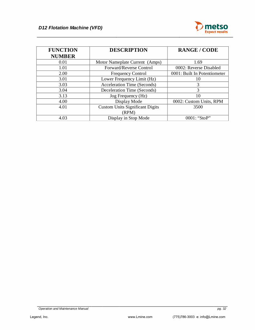
Modifying Default Parameters
Power On; Display Will Blink Press Digits Will Blink Input “Function Number” By Pressing Or To Increase Or Decrease Digit Use To Cycle Between Digits Press Digits Will Blink Again Use Up/Down/Left Arrow Keys To Modify “Range/Code”
Press To Save New Setting Confirms New Setting The “Function Number” Will Blink Again Enter Another “Function Number” To Modify Or Press To Return To Default Display Screen.
Legend, Inc. www.Lmine.com (775)786-3003 e: [email protected]
D12 Flotation Machine (VFD)
Operation and Maintenance Manual pg. 32
FUNCTION NUMBER
DESCRIPTION RANGE / CODE
0.01 Motor Nameplate Current (Amps) 1.69 1.01 Forward/Reverse Control 0002: Reverse Disabled 2.00 Frequency Control 0001: Built In Potentiometer 3.01 Lower Frequency Limit (Hz) 10 3.03 Acceleration Time (Seconds) 3 3.04 Deceleration Time (Seconds) 3 3.13 Jog Frequency (Hz) 10 4.00 Display Mode 0002: Custom Units, RPM 4.01 Custom Units Significant Digits
(RPM) 3500
4.03 Display in Stop Mode 0001: “StoP”
Legend, Inc. www.Lmine.com (775)786-3003 e: [email protected]

D12 Flotation Machine (VFD)
Operation and Maintenance Manual pg. 33
7. Operating instructions 7.1 Starting and Stopping Although all bearings are lubricated before shipment, all bearings should be checked for adequate lubrication prior to initial operation, inspection, and regular use. The machine should be allowed to idle for a brief operation and inspection period of approximately 10 to 15 minutes, prior to introducing feed material.
CAUTION
7.2 Alternate Operations USE OF MACHINE AS AN AGITATOR The flotation machine is easily converted to an agitator by following the instructions in Section 8 (Care / Maintenance & Alternative Setups). The lifting mechanism can be positioned at any desired height for optimum agitation conditions, depending on the tank used and the material being agitated. Also, operating speed should be varied to achieve the most desirable agitating condition. USE OF MACHINE AS AN ATTRITION SCRUBBER The flotation machine is easily converted to an attrition scrubber by following the instructions in Section 8 (Care / Maintenance & Alternative Setups). The opposed propellers of different blade pitch provide maximum movement and rubbing of the mineral particles. The attrition tank is equipped with a cover to prevent splashing or spillage due to violent agitation of the machine. High pulp densities in the order of 70 to 75 percent solids at an approximate speed of 800 rpm are required for efficient scrubbing.
It is extremely important that the MACHINE NOT BE STARTED WITH ANY MATERIAL IN THE TANKS. Prior to daily startup and operation, the machine should be run at the beginning of the day for at least (2) two minutes before feeding any material.
Legend, Inc. www.Lmine.com (775)786-3003 e: [email protected]

D12 Flotation Machine (VFD)
Operation and Maintenance Manual pg. 34
8. Care / Maintenance & Alternate Setups
The proper lubrication of Ore Dressing and Process Equipment is an important factor in obtaining good performance and long service. Heavy loads, shocks, and jars are typical of dressing and processing operations; therefore, lubricants designed to withstand these conditions are essential to assure maximum efficiency. This manual is offered on the basis of careful scientific selection and proven suitability in service. A minimum number of lubricants will provide good dependable lubrication to fill the various requirements. The D12 Flotation machine bearings are packed with Lucas Oil Products “Red N Tacky” #2 Grease from the factory. It is a multi-purpose lithium complex grease with rust and oxidation inhibitors as well as extreme pressure “EP” additives. Grit and ore dust are always present, and if allowed to penetrate, may quickly ruin bearings and gears of the best quality. It is desirable to take due precautions in this regard, keeping abrasive material away from points where it may do harm. Fittings should be wiped clean before the grease gun is applied. Other points of application should be kept free of dirt. The tooth surfaces of open gears should be cleaned before they are re-Iubricated because of the grit which collects from the air. To further ensure exclusion of dirt from the lubricants, all drums and containers should preferably be stored in a clean closed room, their covers kept tightly closed when not in use. Plain sleeve bearings, which are lubricated with grease, should be pumped full to capacity with continued pumping until some of the old grease escapes at the bearing ends. This practice provides a desirable flushing action and also seals the bearing against penetration of foreign matter. The same instructions will apply to antifriction bearings (ball or roller), where excess grease within the housing is free to escape. If there is any doubt about this point, remove the grease fitting or filler plug and let the bearing run until the excess lubricant has been eliminated. Sealed bearings, where grease cannot readily escape, will usually require minimal application, at infrequent intervals. Keep in mind that regular intervals of application are essential to successful results. Operating conditions will largely determine just how often each part must be serviced, but generally speaking, frequent application of lubricants in small quantity is preferred over heavy dosages at longer or irregular intervals. Where the lubricant is continuously reused, such as enclosed worm gear units, etc., the oil should be changed regularly to maintain the necessary purity; freedom from moisture and abrasive matter. Proper intervals for changing oil will depend upon the amount and severity of service, in no case should the intervals exceed one year.
Legend, Inc. www.Lmine.com (775)786-3003 e: [email protected]

D12 Flotation Machine (VFD)
Operation and Maintenance Manual pg. 35
8.1 Safety Measures
WARNING
WARNING Follow all local health and safety instructions: Use approved lifting equipment. Fence of the area around the workplace so that unauthorized persons will not be
injured. 8.2 Suspended Mechanism Spring Adjustment If the suspended mechanism should become hard to raise or lower, adjust the spring tension as follows: a.) Lower mechanism as far as it will go, turn hand crank until the hole in the side of the
spring housing cover lines up with the hole in the hand crank shaft; then insert a nail or pin through these holes.
b.) Remove the four cap screws attaching the spring housing cover to the machine. c.) Turn hand crank counterclockwise 1/4 to 1/2 turn; install and tighten the cap screws removed in step b. d.) Remove nail or pin installed in step a; raise and lower mechanism, and check for ease of movement. If mechanism is still hard to operate, repeat steps a through d until corrected.
Before any work is started, check that the motor is disconnected from the mains or switched off and locked--so that it cannot be started inadvertently.
Freely rotating shaft! When working on or in the vicinity of the shaft with the machine in operation, make sure that all personal equipment is arranged so that it cannot fasten in the rotating parts. Work with care and exercise good judgment!
Legend, Inc. www.Lmine.com (775)786-3003 e: [email protected]

D12 Flotation Machine (VFD)
Operation and Maintenance Manual pg. 36
8.3 Impeller, Diffuser, and Fluidizer Replacement Replace the impeller, diffuser, and fluidizer as follows: a.) Disconnect electrical cable from power source. b.) Raise mechanism to its uppermost position. c.) Hold belt drive, and turn impeller (right hand thread) clockwise until removed from shaft.
NOTE Perform step d only if fluidizer is installed on machine. Fluidizer can be removed
from standpipe after diffuser is removed in step e. d.) Remove rubber bands attaching fluidizer to diffuser. e.) Hold standpipe and turn diffuser (left hand thread) counterclockwise until removed from standpipe.
NOTE Perform step f only if fluidizer is to be installed on machine. Fluidizer has an inside
bevel on one end so it will fit firmly against slope of diffuser. This bevel must face down.
f.) Slip fluidizer on standpipe with beveled end facing down. g.) Install diffuser on standpipe and tighten hand tight. h.) Install impeller on shaft and tighten hand tight.
NOTE Perform step i only if fluidizer is installed on machine.
i.) Attach fluidizer to diffuser with three rubber bands as follows:
1. Pass one end of each rubber band down through fluidizer. 2. Loop these ends over three separate diffuser blades at approximately equal distances around diffuser.
3. Pull loose ends of rubber bands down and over outside of fluidizer and loop over the same diffuser blades used in step 2.
Legend, Inc. www.Lmine.com (775)786-3003 e: [email protected]

D12 Flotation Machine (VFD)
Operation and Maintenance Manual pg. 37
8.4 Converting Machine to Agitator Convert the machine to an agitator as follows:
NOTE Machine can be converted only if the optional kit is furnished with machine.
a.) Disconnect electrical cable from power source. b.) Raise mechanism to its uppermost position. c.) Hold belt drive and turn impeller (right hand thread) clockwise until removed from shaft.
NOTE If standpipe will not unscrew by hand, remove air valve and pipe plug from
standpipe and insert two l/8-inch pipe nipples in their place. Use these nipples to remove standpipe. Do not use a pipe wrench!
d.) Turn standpipe (left hand thread) counterclockwise until removed from machine. e.) Install lower spindle bearing cap (from kit) in place of standpipe. f.) Install single agitator propeller (from kit) on end of shaft. 8.5 Converting Machine to Attrition Scrubber Convert the machine to an attrition scrubber following instructions in “Converting Machine to Agitator” except in step f, the one-piece double attrition propeller is installed on the shaft, instead of the single agitator propeller.
Legend, Inc. www.Lmine.com (775)786-3003 e: [email protected]

D12 Flotation Machine (VFD)
Operation and Maintenance Manual pg. 38
8.6 Bearing Replacement REMOVAL Remove bearings as follows: a.) Disconnect electrical cable from power source. b.) Raise mechanism to its uppermost position. c.) Turn speed control knob to its uppermost position in drive guard.
NOTE Perform step d only if tachometer is furnished with machine.
d.) Loosen set screw on side of tachometer adapter base to free flexible coupling. e.) Remove hex nut attaching drive guard to machine and remove drive guard. f.) Loosen set screws attaching motor bracket to machine, slide motor toward machine, and remove belt. g.) Hold shaft and turn impeller (right hand thread) clockwise until removed from shaft.
NOTE If standpipe will not unscrew by hand, remove air valve and pipe plug from
standpipe and insert two 1/8-inch pipe nipples in their place. Use these nipples to remove standpipe. Do not use a pipe wrench!
h.) Turn standpipe (left hand thread) counterclockwise until removed from machine. i.) Remove upper spindle bearing cap (right hand thread). j.) Place a piece of hardwood on the top of the shaft and carefully hammer the shaft downward to free it from the bearings, then remove shaft from machine. k.) Remove bearings and inspect for damage or excessive wear. Replace as required. INSTALLATION Install bearings as follows: a.) Thoroughly clean all parts to remove old grease, dirt etc.
NOTE Bearings are attached to shaft by a firm pressure fit.
b.) Place lower bearing on shaft and insert shaft and bearing up into the spindle bearing housing. c.) Pack with grease (Lucas Oil “Red N Tacky” #2 grease or equivalent). d.) Install standpipe on machine and tighten hand tight. e.) Install upper bearing on shaft. Insure bearing is tight against shaft shoulder.
Legend, Inc. www.Lmine.com (775)786-3003 e: [email protected]

D12 Flotation Machine (VFD)
Operation and Maintenance Manual pg. 39
f.) Pack with grease and install spacers and upper spindle bearing cap. Tighten cap hand tight. g.) Check shaft for end play or if it is too tight. If there is end play, or shaft is too tight, remove or add spacers as required until there is no end play and shaft is adequately tight. h.) Install belt and adjust tension by sliding motor away from machine. Tighten set screws attaching motor bracket to machine when proper tension of belt is obtained. i.) Install drive guard on machine with hex nut.
NOTE Perform step j only if tachometer is furnished with machine.
j.) Tighten set screw on side of tachometer base to secure flexible coupling.
LUBRICATION
The bearings on the machine are sealed bearings, requiring no periodic lubrication. After prolonged use, it may be necessary to repack the bearings; repack bearings in accordance with the instructions listed earlier.
Legend, Inc. www.Lmine.com (775)786-3003 e: [email protected]

D12 Flotation Machine (VFD)
Operation and Maintenance Manual pg. 40
9. Spare Parts
9.1 Recommended Spare Parts Stock
We recommend an ample supply of parts be kept on hand to prevent unnecessary downtime and loss of production.
Following is a list of parts and quantities recommended by Metso to be stocked as spares for the flotation machine:
Description Qty Part # SAP # IMPELLER 1 201588 777011435 HOOD 1 500333 777011409 IMPELLER 1 200563 777011433 HOOD 1 500390 777011431 BEARING 2 524615 CONE;
524663 CUP 777011378 777011384
V-BELT (legacy) 1 520359 777011450
9.2 Spare Parts Drawing
See below drawings D-28179, pages 1 and 2 for general machine assembly (legacy).
Legend, Inc. www.Lmine.com (775)786-3003 e: [email protected]

Legend, Inc. www.Lmine.com

Legend, Inc. www.Lmine.com