Laboratory Manual Theory of Machine & Mechanism Lab
17
Laboratory Manual Theory of Machine & Mechanism Lab Diploma IV th Semester Mechanical Engineering
Transcript of Laboratory Manual Theory of Machine & Mechanism Lab

Laboratory Manual
Theory of Machine &
Mechanism Lab
Diploma
IVth Semester
Mechanical Engineering

List of Experiments:
1 Study of Ackerman’s Steering Gear Mechanism.
2 To study various types of gears.
3 To study various types of gear trains
4 To draw velocity diagram of slider crank mechanism.
5 To draw acceleration diagram of four bar mechanism.
6 To draw displacement diagram, velocity diagram & acceleration diagram of cam follower.

EXPERIMENT No: 1 AIM: Study of Ackerman’s Steering Gear Mechanism. APPARATUS USED: Steering Mechanism Apparatus. THEORY: Definition of Steering mechanisms, Classification of steering mechanisms, Diagrams of steering mechanisms, Working & Construction. STEERING GEAR: When an automobile takes turn on a road all the wheels should make concentric circle to ensure that they roll on the road smoothly and there is line contact between the tyres and the surface of the path, preventing the excess wear of the tyre. This is achieved by mounting the two front wheels on two short axles, known as stub axles. The stub axles are pin-jointed with the main front axle which is rigidly attached to the rear axle. Thus the steering is affected by the use of front wheels only. TYPES OF STERING GEARS: There are two main types of steering gears:
1. The Davis steering Gear 2. The Ackermann steering gear
DAVIS STEERING GEAR : A Davis steering gear has sliding pairs which means more friction and easy wearing. The gear fulfils the fundamental equation of gearing in all the positions. However, due to easy wearing it becomes inaccurate after some time
ACKERMANN STEERING GEAR: An Ackermann steering gear has only turning pairs and thus is preferred. Its drawback is that it fulfils the fundamental equation of correct gearing at the middle and the two extreme position and not in all positions. This steering gear consists of a four link mechanism having four-turning pairs. Three positions of the correct gearing are- 1.when the vehicle moves straight. 2. when the vehicle moves at a correct angle to the right, and 3. when the vehicle moves at a correct angle to the left. In the Ackerman steering gear, the mechanism ABCD is a four bar crank chain, as shown in figure below. The shorter links BC and AD are of equal length and are connected by hinge joint with front wheel axles. The longer links AB and CD are of unequal length.

The following are the only three positions for correct steering.
1. When the vehicle moves along a straight path, the longer links AB and CD are parallel and the shorter links BC and AD are equally inclined to the longitudinal axis of the vehicle, as shown by firm lines in the figure. 2. When the vehicle is steering to the left, the position of the gear is shown by dotted lines in the figure. In this position, the lines of the front wheel axle intersect on the back wheel axle at I, for correct steering 3. When the vehicle is steering to the right, a similar position may be obtained again. Sometimes incorrect steering condition with a combination of high speeds and bad road conditions can lead to over and under steer. These are the two major drawback of incorrect steering. 1. Under steer occurs during a turn of a corner, when you try to turn the vehicle but it continues in a straight line, heading off the road. This occurs because the front tyres have reached their adhesion limit and cannot grip the road adequately enough to turn. The best way to correct under steer is to brake, release break, steer in the opposite desired direction and quickly change back to turning in the correct direction. However, you should not brake into a corner as this will cause further under steer, rather try and brake on the straightest line possible. This will ensure the cars slow down enough to regain enough grip to turn. 2. Over steer occurs when turning a corner and the vehicles back slides out as the rear wheels do not have enough grip to complete the turn. To counter such an even do not accelerate further through the corner, but rather very carefully break gently in the straightest manner possible. Full force braking can become more dangerous than helpful. However, braking gently can correct your steering in situations such as over steer. OBSERVATION & CONCLUSION: Ackerman steering gear mechanism was studied and is preferred one. The Ackerman steering gear mechanism is much simpler than Davis steering gear and hence quite popular.
EXPERIMENT No: 2 AIM:

To study various types of gears. APPARATUS USED: Arrangement of gear system. THEORY: Definition of gear, Classification of gear, Diagram of different type of gear, Working and construction of different type of gear and Example of gear. GEAR: Gears are used to transmit motion from one shaft to another shaft or between a shaft or slide. This is accomplished by successively engaging teeth. CLASSIFICATION OF GEAR: Gears can be classified according to the relative position of their shaft axis are follows: A: PARALLEL SHAFT
I. Spur gear. II. Spur rack and pinion III. Helical gears or Helical spur gear IV. Double- helical and Herringbone gear
B: INTER SECTING SHAFT I. Straight bevel gear II. Spiral bevel gear
C: SKEW SHAFT I. Crossed- helical gear II. Worm gears
Spur gear: They have straight teeth parallel to the axes and thus are not subjected to axial thrust due to teeth load.
Spur Gear Helical Gear Helical gears: In helical gears, the teeth are curved, each being helical in shape. Two mating gears have the same helix angle, but have teeth of opposite hands. At the beginning of engagement, contact occurs only at the point of leading edge of the curved teeth. As the gears rotate, the contact extends along a diagonal line across the teeth. Thus the load application is gradual which result in low impact stresses and reduction in noise. Therefore, the helical gears can be used at higher velocities than the spur gears and have greater load carrying capacity.
Double Helical and Herring Bone Gears:

A double helical gear is equivalent to a pair of helical gears secured together, one having a right – hand helix and the other a left hand helix.
Herringbone Gear Double Helical Gear The tooth of two row is separated by a grooved used for tool run out. If the left and the right inclinations of a double – helical gear meet at a common apex and there is no groove in between, the gear is known as herring bone gear.
Crossed – Helical Gear: The used of crossed helical gear or spiral gears is limited to light loads. By a suitable choice of helix angle for the mating gears, the two shaft can be set at any angle.
Worm Gear: Worm gear is a special case of spiral gear in which the larger wheel, usually, has a hollow or concave shape such that a portion of the pitch diameter is the other gear is enveloped on it. The smaller of two wheels is called the worm which also has larger spiral angle.
Bevel Gear:

Kinematically, the motion between two intersecting shafts is equivalent to the rolling of two cones, assuming no slipping. The gears, in general, are known as bevel gear. When teeth formed on the cones are straight, the gear is known as straight bevel and when inclined, they are known as spiral or helical bevel.
APPLICATION: 1. Bevel gears are used for the drive to the differential of automobiles. 2. Spur rack and pinion are used in a lathe. 3. Helical gears are used for greater load at higher velocities. 4.Gears are used in different machinery. CONCLUSION: Various gears were studied.
EXPERIMENT No: 3 AIM:

To study various types of gear trains. APPARATUS USED: Arrangement of Gear train system. THEORY: Definition of Gear train, Classification of Gear train, Diagrams of different types of Gear train,Working & Construction of different types of Gear train. GEAR TRAIN: A gear train is a combination of gears used to transmit motion from one shaft to another. It becomes necessary when it is required to obtain large speed reduction within a small space. The following are the main types of gear trains:
1. Simple gear train 2. Compound gear train 3. Reverted gear train 4. Planetary gear train 5. Differential gear train
SIMPLE GEAR TRAIN: A series of gears, capable of receiving and transmitting motion from one gear to another is called a simple gear train. In it, all the gear axes remain fixed relative to the frame and each gear is on a separate shaft.
Train Value = (Number of teeth on driving gear) /( Number of teeth on driven gear ) COMPOUND GEAR TRAIN: When a series of gears are connected in such a way that two or more gears rotate about an axis with the same angular velocity, it is known as compound gear train.
Train Value = (Product of Number of teeth on driving gear /Product of Number of teeth on driven gear) REVERTED GEAR TRAIN:

If the axes of the first and last wheels of a compound gear coincide; it is called a reverted gear train. Such an arrangement is used in clocks and in simple lathes where ‘back gear’ is used to give a slow speed to the chuck.
Train Value = (Product of Number of teeth on driving gear/Product of Number of teeth on driven gear ) PLANETARY OR EPICYCLIC GEAR TRAIN : When there exist a relative motion of axis in gear train, it is called a planetary or an epicyclic gear train (or simply epicyclic gear or train). Thus in an epicyclic train, the axis of at least one of the gears also moves relative to the frame. Consider two gear wheels, the axis of which are connected by an arm . if the arm is fixed, the wheels constitute a simple train. However, if the wheel s is fixed so that the arm can rotate about the axis of S, the wheel P would also move around S. therefore, it is an epicyclic train.
DIFFERENTIAL GEAR:

When a vehicle takes a turn, the outer wheels must travel farther than the inner wheels. In automobiles, the front wheels can rotate freely on their axis and thus can adapt themselves to the conditions. Both rear wheels are driven by the engine through gearing. Therefore, some sort of automatic device is necessary so that the two rear wheels are driven at slightly different speeds. This is accomplished by fitting a differential gear on the rear axle.
APPLICATIONS: Gear trains are used in automobiles. Reverted gear train are used in clock and simple lathe. Epicyclicgear are used in transmission, computing devices. Gears are used in different machinery. CONCLUSION: Simple, compound reverted, epicyclic and differential gears were studied

EXPERIMENT No: 4
AIM: To draw velocity diagram of slider crank mechanism. PROBLEM: The crank of a slider crank mechanism rotates clockwise at a constant speed of 300 r.p.m. The crank is 150 mm and the connecting rod is 600 mm long. Determine : 1. Linear velocity and of the midpoint of the connecting rod, and 2. angular velocity of the connectingrod, at a crank angle of 45° from inner dead centre position. SOLUTION: Given : NBO = 300 r.p.m. or ωBO = 2 π × 300/60 = 31.42 rad/s; OB = 150 mm =0.15 m ; BA = 600 mm = 0.6m. We know that linear velocity of B with respect to O or velocity of B, vBO = vB = ωBO × OB = 31.42 × 0.15 = 4.713 m/s...(Perpendicular to BO)
Velocities in Slider Crank Mechanism
First of all draw the space diagram, to some suitable scale; as shown in Fig. Now the velocity diagram, as is drawn as discussed below: 1. Draw vector ob perpendicular to BO, to some suitable scale, to represent the velocity of B with
respect to O or simply velocity of B i.e. vBO or vB, such that vector ob = vBO = vB = 4.713 m/s. 2. From point b, draw vector ba perpendicular to BA to represent the velocity of A with respect to B i.e.
vAB , and from point o draw vector oa parallel to the motion of A (which is along AO) to represent the velocity of A i.e. vA. The vectors ba and oa intersect at a.By measurement, we find that velocity of A with respect to B,
vAB=vector ba= 3.4 m / s and Velocity of A ,vA= vector oa= 4 m / s.
3. In order to find the velocity of the midpoint D of the connecting rod A B, divide the vector ba at d in the same ratio as D divides A B, in the space diagram. In other words,
bd / ba = BD/BA Since D is the midpoint of A B, therefore d is also midpoint of vector ba. 4. Join od. Now the vector od represents the velocity of the midpoint D of the connecting rod i.e. vD
By measurement, we find that vD = vector od = 4.1 m/s Ans.
CONCLUSION: The velocity diagram of slider crank was drawn and analysed.
EXPERIMENT No: 5

AIM:
To draw acceleration diagram of four bar mechanism.
PROBLEM: The dimensions and configuration of the four bar mechanism, shown in Figure, are as follows: P1A = 300 mm; P2B = 360 mm; AB = 360mm, and P1P2 = 600 mm. The angle AP1P2= 60°. The crank P1A has an angular velocity of 10 rad/s and an angular acceleration of 30 rad/s2, both clockwise. Determine the angular acceleration of P2B, and AB and the velocity of the joint B. SOLUTION: Given : ωAP1 = 10 rad/s ; αAP1 = 30 rad/s2; P1A = 300 mm = 0.3 m ; P2B = AB =360 mm = 0.36 m. We know that the velocity of A with respect to P1 or velocity of A, VAP1 = VA = ωAP1 × P1A = 10 × 0.3 = 3 m/s.
VELOCITY DIAGRAM:
1. Choosing appropriate scale; draw vector ap (VAP1=3 m/s).
2. Draw fixed point P1& P2 by single point in velocity diagram.
3. From point a, draw vector ab perpendicular to AB to represent velocity of B with respect to A. 4. From point P2 draw vector P2b perpendicular to P2B to represent the velocity of B with respect to P2 or velocity of B. 5.The vectors ab and p2b intersect at b. 6. By measurement, we find that p2b = 2.2 m/s 7. We know that angular velocity of P2B,and angular velocity of AB:
ACCELERATION DIAGRAM:
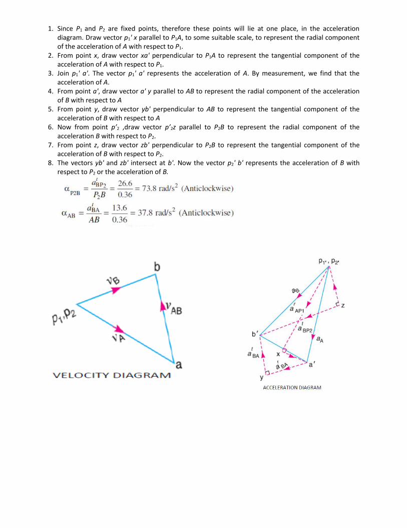
1. Since P1 and P2 are fixed points, therefore these points will lie at one place, in the acceleration diagram. Draw vector p1' x parallel to P1A, to some suitable scale, to represent the radial component of the acceleration of A with respect to P1.
2. From point x, draw vector xa' perpendicular to P1A to represent the tangential component of the acceleration of A with respect to P1.
3. Join p1' a'. The vector p1' a' represents the acceleration of A. By measurement, we find that the acceleration of A.
4. From point a', draw vector a' y parallel to AB to represent the radial component of the acceleration of B with respect to A
5. From point y, draw vector yb' perpendicular to AB to represent the tangential component of the acceleration of B with respect to A
6. Now from point p’2 ,draw vector p’2z parallel to P2B to represent the radial component of the acceleration B with respect to P2.
7. From point z, draw vector zb' perpendicular to P2B to represent the tangential component of the acceleration of B with respect to P2.
8. The vectors yb' and zb' intersect at b'. Now the vector p2' b' represents the acceleration of B with respect to P2 or the acceleration of B.

EXPERIMENT No: 6 AIM: To draw displacement diagram, velocity diagram & acceleration diagram of cam follower. THEORY: Types of Follower motion: (1)Simple Harmonic Motion (2) Uniform Velocity (3) Uniform Acceleration and Retardation (4) Cycloidal Motion
1. Displacement, Velocity and Acceleration Diagrams when the Follower Moves with Uniform Velocity: The displacement, velocity and acceleration diagrams when a knife-edged follower moves with uniform velocity are shown in Fig.1

2.Displacement, Velocity and Acceleration Diagrams when the Follower Moves with Simple Harmonic Motion: The displacement, velocity and acceleration diagrams when the follower moves with simple harmonic
motion are shown in above Fig.2

3. Displacement, Velocity and Acceleration Diagrams when the Follower Moves with Uniform Acceleration and Retardation: The displacement, velocity and acceleration diagrams when the follower moves with uniform acceleration and retardation are shown in Fig.3
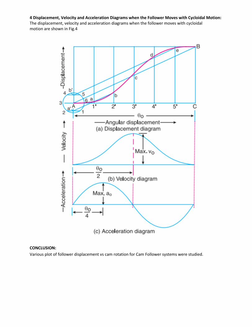
4 Displacement, Velocity and Acceleration Diagrams when the Follower Moves with Cycloidal Motion: The displacement, velocity and acceleration diagrams when the follower moves with cycloidal motion are shown in Fig.4
CONCLUSION:
Various plot of follower displacement vs cam rotation for Cam Follower systems were studied.