Lab 9 - Centre for Assistive Technology in text form... · Web viewFAO/1 FAO/1 Trunk" ISL~' VLAN...
71
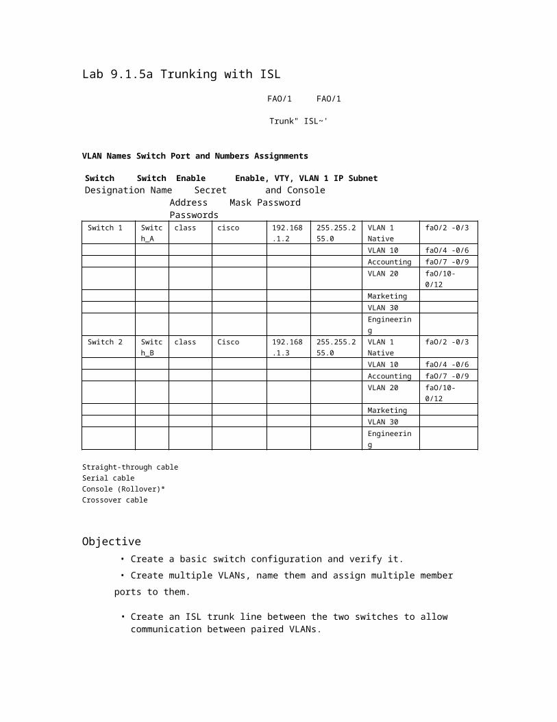
Lab 9.1.5a Trunking with ISL FAO/1 FAO/1 Trunk" ISL~' VLAN Names Switch Port and Numbers Assignments Switch Switch Enable Enable, VTY, VLAN 1 IP Subnet Designation Name Secret and Console Address Mask Password Passwords Switch 1 Switc h_A class cisco 192.168 .1.2 255.255.2 55.0 VLAN 1 Native faO/2 -0/3 VLAN 10 faO/4 -0/6 Accounting faO/7 -0/9 VLAN 20 faO/10- 0/12 Marketing VLAN 30 Engineerin g Switch 2 Switc h_B class Cisco 192.168 .1.3 255.255.2 55.0 VLAN 1 Native faO/2 -0/3 VLAN 10 faO/4 -0/6 Accounting faO/7 -0/9 VLAN 20 faO/10- 0/12 Marketing VLAN 30 Engineerin g Straight-through cable Serial cable Console (Rollover)* Crossover cable Objective • Create a basic switch configuration and verify it. • Create multiple VLANs, name them and assign multiple member ports to them. • Create an ISL trunk line between the two switches to allow communication between paired VLANs.
Transcript of Lab 9 - Centre for Assistive Technology in text form... · Web viewFAO/1 FAO/1 Trunk" ISL~' VLAN...
Lab 9.1.5a Trunking with ISL
FAO/1 FAO/1
Trunk" ISL~'
VLAN Names Switch Port and Numbers Assignments
Switch Switch Enable Enable, VTY, VLAN 1 IP Subnet Designation Name Secret and Console Address Mask
Password Passwords Switch 1 Switch
_A class cisco 192.168.1
.2 255.255.255.0
VLAN 1 Native
faO/2 -0/3
VLAN 10 faO/4 -0/6 Accounting faO/7 -0/9 VLAN 20 faO/10-0/12 Marketing VLAN 30 Engineering
Switch 2 Switch_B
class Cisco 192.168.1.3
255.255.255.0
VLAN 1 Native
faO/2 -0/3
VLAN 10 faO/4 -0/6 Accounting faO/7 -0/9 VLAN 20 faO/10-0/12 Marketing VLAN 30 Engineering
Straight-through cable Serial cable Console (Rollover)* Crossover cable
Objective • Create a basic switch configuration and verify it.
• Create multiple VLANs, name them and assign multiple member ports to them.
• Create an ISL trunk line between the two switches to allow communication between paired VLANs.
• Test the VLANs functionality by moving a workstation from one VLAN to another.
Background/Preparation
Note: The use of Catalyst 2950 switches is not appropriate for this lab as they only support 802.1q trunking.
Trunking changes the formatting of the packets. The ports need to be in agreement as to which format is being used to transmit data on the trunk or no data will be passed. If there is different trunking encapsulation on the two ends of the link they will not able to communicate. Similar situation will occur if one of the ports is configured in trunking mode, unconditionally, and the other one is in access mode, unconditionally.
1 -8 CCNA 3: Switching Basics and Intermediate Routing v 3.1 -Lab 9.1.5a Copyright © 2003, Cisco Systems, Inc.
When managing a switch, the Management Domain is always VLAN 1. The Network Administrator's workstation must have access to a port in the VLAN 1 Management Domain. All ports are assigned to VLAN 1 by default. This lab will also help demonstrate how VLANs can be used to separate traffic.
Cable a network similar to the one in the diagram. The configuration output used in this lab is produced from a 2900 series switch. Any other switch used may produce different output. The following steps are to be executed on each switch unless specifically instructed otherwise.
Start a HyperTerminal session.
Note: Go to the erase and reload instructions at the end of this lab. Perform those steps on all switches in this lab assignment before continuing.
Step 1 Configure the switch
Configure the hostname, access and command mode passwords, as well as the management LAN settings. These values are shown in the chart. If problems occur while performing this configuration, refer to the Basic Switch Configuration lab.
Step 2 Configure the hosts attached to the switch
Configure the IP address, mask, and default gateway on each host. Be sure to choose addresses that are on the same subnet as the switch.
Step 3 Verify connectivity
a. To verify that the host and switch are correctly configured, ping the switches from the host.
b. Were the pings successful?
c. If the answer is no, troubleshoot the host and switches configurations.
Step 4 Display the VLAN interface information
On Switch_A, type the command show vlan at the Privileged EXEC prompt as follows:
Switch_A#show vlan
Note: There should be an entry for VLAN 1 and the default VLANs (1002 +). If other VLANs appear, they could be deleted as instructed in Step 2 of the Erasing and Reloading instructions at the end of this lab or refer to the Lab Exercise: Deleting VLAN Configurations.
Step 5 Create and name three VLANs
Enter the following commands to create and name three VLANs:
Switch_A#vlan database
Switch_A(vlan)#vlan 10 name Accounting Switch_A(vlan)#vlan 20 name Marketing Switch_A(vlan)#vlan 30 name Engineering Switch_A(vlan)#exit
Use the show vlan command to verify that the VLANs have been created correctly.
2 -8 CCNA 3: Switching Basics and Intermediate Routing v 3.1 -Lab 9.1.5a Copyright © 2003, Cisco Systems, Inc.

Step 6 Assign ports to a VLAN 10
Assigning ports to VLANs must be done from the interface mode. Enter the following commands to add ports 0/4 to 0/6 to VLAN 10:
Switch_A#configure terminal Switch_A(config)#interface fastethernet 0/4 Switch_A(config-if)#switchport mode access Switch_A(config-if)#switchport access vlan 10 Switch_A(config-if)#interface fastethernet 0/5 Switch_A(config-if)#switchport mode access Switch_A(config-if)#switchport access vlan 10 Switch_A(config-if)#interface fastethernet 0/6 Switch_A(config-if)#switchport mode access Switch_A(config-if)#switchport access vlan 10 Switch_A(configif)#end
Step 7 Assign ports to VLAN 20
Enter the following commands to add ports 0/7 to 0/9 to VLAN 20:
Switch_A#configure terminal Switch_A(config)#interface fastethernet 0/7 Switch_A(config-if)#switchport mode access Switch_A(config-if)#switchport access vlan 20 Switch_A(config-if)#interface fastethernet 0/8 Switch_A(config-if)#switchport mode access Switch_A(config-if)#switchport access vlan 20 Switch_A(config-if)#interface fastethernet 0/9 Switch_A(config-if)#switchport mode access Switch_A(config-if)#switchport access vlan 20 Switch_A(configif)#end
Step 8 Assign ports to VLAN 30
Enter the following commands to add ports 0/10 to 0/12 to VLAN 30:
Switch_A#configure terminal Switch_A(config)#interface fastethernet 0/10 Switch_A(config-if)#switchport mode access Switch_A(config-if)#switchport access vlan 30 Switch_A(config-if)#interface fastethernet 0/11 Switch_A(config-if)#switchport mode access Switch_A(config-if)#switchport access vlan 30 Switch_A(config-if)#interface fastethernet 0/12 Switch_A(config-if)#switchport mode access Switch_A(config-if)#switchport access vlan 30 Switch_A(configif)#end
Step 9 Create VLANs on Switch_B
Repeat Steps 5 through 8 on Switch_B to create its VLANs.
3 -8 CCNA 3: Switching Basics and Intermediate Routing v 3.1 -Lab 9.1.5a Copyright © 2003, Cisco Systems, Inc.
Step 10 Display the VLAN interface information
a. On Switch_A, type the command show vlan at the Privileged EXEC prompt as follows:
Switch_A#show vlan
b. Are ports 0/10 through 0/12 assigned to VLAN 30?
Step 11 Test the VLANs Ping from the host in Switch_A port 0/12 to the host in Switch_B port 0/12.
a. Was the ping successful?
b. Why?
Ping from the host in Switch_A port 0/12 to the switch IP 192.168.1.2.
c. Was the ping successful?
d. Why?
Step 12 Create the ISL trunk
On both switches, Switch_A and Switch_B, type the following command at the fastethernet 0/1 interface command prompt
Switch_A(config)#interface fastethernet 0/1 Switch_A(config-if)#switchport mode trunk Switch_A(config-if)#switchport trunk encapsulation isl Switch_A(configif)#end
Switch_B(config)#interface fastethernet 0/1 Switch_B(config-if)#switchport mode trunk Switch_B(config-if)#switchport trunk encapsulation isl Switch_B(configif)#end
Step 13 Verify the ISL trunk


a. To verify that port fastethernet 0/1 has been established as a trunk port, type show interface fastethernet 0/1 switchport at the Privileged EXEC mode prompt.
b. What type of trunking encapsulation is shown on the output results?

c. According to the output with show interface fastethernet 0/1 switchport on Switch_B, is there a difference from the Administrative Trunking Encapsulation from the Operational Trunking Encapsulation?
d. On the fragment "Trunking VLANs Enable" from the output, what does the word "ALL" mean?
e. What would happen if the two ports of the trunk were using different encapsulation?
f. Explain.
4 -8 CCNA 3: Switching Basics and Intermediate Routing v 3.1 -Lab 9.1.5a Copyright © 2003, Cisco Systems, Inc.

Step 14 Test the VLANS and the trunk Ping from the host in Switch_A port 0/12 to the host in
Switch_B port 0/12.
a. Was the ping successful?
b. Why?
Ping from the host in Switch_A port 0/12 to the switch IP 192.168.1.2.
c. Was the ping successful?
d. Why?
Step 15 Move host
Move the host in Switch_A from port 0/12 to port 0/8. Wait until the port LED goes green and then go to the next step.
Step 16 Test the VLANS and the trunk Ping from the host in Switch_A port 0/8 to the host in Switch_B port 0/12.
a. Was the ping successful?
b. Why? __
Ping from the host in Switch_A port 0/8 to the switch IP 192.168.1.2.
c. Was the ping successful?
d. Why? __
Step 17 Move host
Move the host in Switch_B from port 0/12 to port 0/7. Wait until the port LED goes green and then go to the next step.
Step 18 Test the VLANS and the trunk Ping from the host in Switch_A port 0/8 to the host in Switch_B port 0/7.
a. Was the ping successful?
b. Why? __
Ping from the host in Switch_A port 0/8 to the switch IP 192.168.1.2.
c. Was the ping successful?
d. Why? __
Step 19 Move host
Move the host in Switch_A from port 0/8 to port 0/2. Wait until the port LED goes green and then go to the next step.
Step 20 Test the VLANS and the trunk

Ping from the host in Switch_A port 0/2 to the host in Switch_B port 0/7.
a. Was the ping successful?
Ping from the host in Switch_A port 0/2 to the switch IP
192.168.1.2. b. Was the ping successful?
5-8 CCNA 3: Switching Basics and Intermediate Routing v 3.1 -Lab 9.1.5a Copyright © 2003, Cisco Systems, Inc.

c. Why? __
Step 21 Move host
Move the host in Switch_B from port 0/7 to port 0/3. Wait until the port LED goes green and then go to the next step.
Step 22 Test the VLANS and the trunk Ping from the host in Switch_A port 0/2 to the host in Switch_B port 0/3.
a. Was the ping successful?
b. Why? __
Ping from the host in Switch_B port 0/3 to the switch IP 192.168.1.2.
c. Was the ping successful?
d. Why? __
Ping from the host in Switch_B port 0/3 to the switch IP 192.168.1.3.
e. Was the ping successful?
f. Why? __
g. What conclusions can be drawn from the testing that was just performed in regards to VLAN membership and VLANs across a trunk?
Once the steps are complete, logoff by typing exit, and turn all the devices off. Then remove and store the cables and adapter.
6 -8 CCNA 3: Switching Basics and Intermediate Routing v 3.1 -Lab 9.1.5a Copyright © 2003, Cisco Systems, Inc.
Erasing and Reloading the Switch
For the majority of the labs in CCNA 3 and CCNA 4 it is necessary to start with an unconfigured switch. Use of a switch with an existing configuration may produce unpredictable results. These instructions allow preparation of the switch prior to performing the lab so previous configuration options do not interfere. The following is the procedure for clearing out previous configurations and starting with an unconfigured switch. Instructions are provided for the 2900, 2950, and 1900 Series switches.
2900 and 2950 Series Switches
1. Enter into the Privileged EXEC mode by typing
enable. Switch > enable
If prompted for a password, enter class, if that does not work, ask the instructor.
2. Remove the VLAN database information file.
Switch#delete flash:vlan.dat Delete filename [vlan.dat]?[Enter] Delete flash:vlan.dat? [confirm] [Enter]
If there was no VLAN file, this message is displayed.
%Error deleting flash:vlan.dat (No such file or directory)
3. Remove the switch startup configuration
file from NVRAM. Switch#erase startup-
config
The responding line prompt will be:
Erasing the nvram filesystem will remove all files! Continue? [confirm]
Press Enter to confirm. The response should be:
Erase of nvram: complete
4. Check that VLAN information was deleted.

Verify that the VLAN configuration was deleted in Step 2 using the show vlan command. If previous VLAN configuration information (other than the default management VLAN 1) is still present it will be necessary to power cycle the switch (hardware restart) instead of issuing the reload command. To power cycle the switch, remove the power cord from the back of the switch or unplug it. Then plug it back in.
If the VLAN information was successfully deleted in Step 2, go to Step 5 and restart the switch using the reload command.
5. Software restart (using the reload command)
7 -8 CCNA 3: Switching Basics and Intermediate Routing v 3.1 -Lab 9.1.5a Copyright © 2003, Cisco Systems, Inc.
Note: This step is not necessary if the switch was restarted using the power cycle method.
a. At the Privileged EXEC mode enter the command reload.
Switch(config)#reload
The responding line
prompt will be:
System configuration has been modified. Save? [yes/no]:
b. Type n and then press
Enter. The responding
line prompt will be:
Proceed with reload? [confirm]
[Enter] The first line of the response will
be:
Reload requested by console.
After the switch has reloaded, the line prompt will be:
Would you like to enter the initial configuration dialog?
[yes/no]:
c. Type n and then press
Enter. The responding
line prompt will be:
Press RETURN to get started! [Enter]
1900 Series Switches
1. Remove VLAN Trunking Protocol (VTP) information.
ttdelete vtp This command resets the switch with VTP parameters set to factory defaults. All other parameters will be unchanged.
Reset system with VTP parameters set to factory defaults, [Y]es or [N]o?
Enter y and press Enter.
2. Remove the switch startup configuration from NVRAM.
#delete nvram
This command resets the switch with factory defaults. All system parameters will revert to their default factory settings. All static and dynamic addresses will be removed.
Reset system with factory defaults,
[Y]es or [N]o? Enter y and press Enter.
8 -8 CCNA 3: Switching Basics and Intermediate Routing v 3.1 -Lab 9.1.5a Copyright © 2003, Cisco Systems, Inc.
Cisco Systems
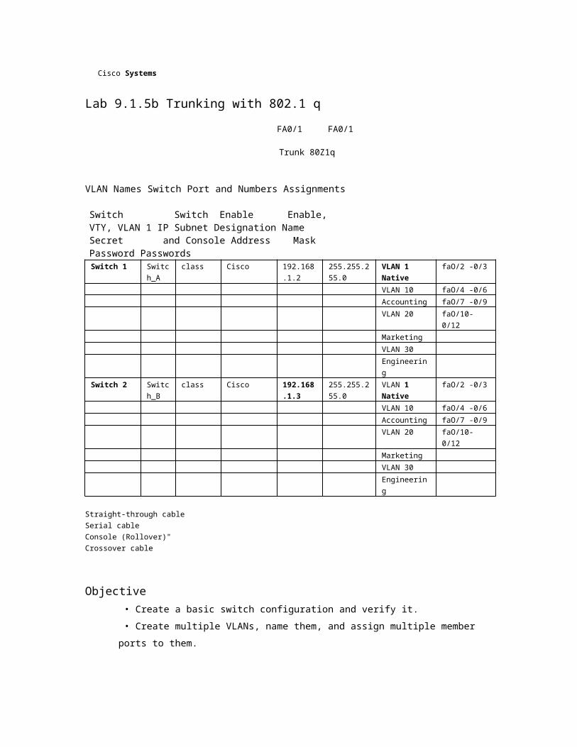
Lab 9.1.5b Trunking with 802.1 q
FA0/1 FA0/1
Trunk 80Z1q
VLAN Names Switch Port and Numbers Assignments
Switch Switch Enable Enable, VTY, VLAN 1 IP Subnet Designation Name Secret and Console Address Mask Password Passwords Switch 1 Switch
_A class Cisco 192.168.1
.2 255.255.255.0
VLAN 1 Native
faO/2 -0/3
VLAN 10 faO/4 -0/6 Accounting faO/7 -0/9 VLAN 20 faO/10-0/12 Marketing VLAN 30 Engineering
Switch 2 Switch_B
class Cisco 192.168.1.3
255.255.255.0
VLAN 1 Native
faO/2 -0/3
VLAN 10 faO/4 -0/6 Accounting faO/7 -0/9 VLAN 20 faO/10-0/12 Marketing VLAN 30 Engineering
Straight-through cable Serial cable Console (Rollover)" Crossover cable
Objective • Create a basic switch configuration and verify it.
• Create multiple VLANs, name them, and assign multiple member ports to them.


• Create an 802.1 q trunk line between the two switches to allow communication between paired VLANs.
• Test the VLANs functionality by moving a workstation from one VLAN to another.
Background/Preparation
Trunking changes the formatting of the packets. The ports need to be in agreement as to which format is being used to transmit data on the trunk or no data will be passed. If there is different trunking encapsulation on the two ends of the link they will not able to communicate. Similar situation will occur if one of the ports is configured in trunking mode (unconditionally) and the other one is in access mode (unconditionally).
When managing a switch, the Management Domain is always VLAN 1. The Network Administrator's workstation must have access to a port in the VLAN 1 Management Domain. All ports are assigned to VLAN 1 by default. This lab will also help demonstrate how VLANs can be used to separate traffic and reduce broadcast domains.
1 -8 CCNA 3: Switching Basics and Intermediate Routing v 3.1 -Lab 9.1.5b Copyright © 2003, Cisco Systems, Inc.

Cable a network similar to one of the diagram. The configuration output used in this lab is produced from 2950 series switch. Any other switch used may produce different output. The following steps are intended to be executed on each switch unless specifically instructed otherwise.
Start a HyperTerminal session.
Note: Go to the erase and reload instructions at the end of this lab. Perform those steps on all switches in this lab assignment before continuing.
Step 1 Configure the switch
Configure the Hostname, access and command mode passwords, as well as the management LAN settings. These values are shown in the chart. If problems occur while performing this configuration, refer to the "Basic Switch Configuration lab". Do not configure VLANs and trunking yet.
Step 2 Configure the hosts attached to the switch
Configure the IP address, mask, and default gateway on each host. Be sure to choose addresses that are on the same subnet as the switch.
Step 3 Verify connectivity
a. To verify that the host and switch are correctly configured, ping the switch from the hosts.
b. Were the pings successful?
c. If the answer is no, troubleshoot the host and switches configurations.
Step 4 Display the VLAN interface information
On Switch_A, type the command show vlan at the Privileged EXEC prompt as follows:
Switch_A#show vlan
Note: There should be an entry for VLAN 1 and the default VLANs (1002 +). If other VLANs appear, they could be deleted as instructed in Step 2 of the Erasing and Reloading instructions at the end of this lab or refer to the Lab Exercise: Deleting VLAN Configurations.
Step 5 Create and name three VLANs
Enter the following commands to create and name three VLANs:
Switch A#vlan database Switch_A(vlan)#vlan 10 name Accounting Switch A(vlan)ivlan 20 name Marketing Switch_A(vlan)#vlan 30 name Engineering

Switch_A(vlan)#exit
Use the show vlan command to verify that the VLANs have been created correctly.
Step 6 Assign ports to a VLAN 10
Assigning ports to VLANs must be done from the interface mode. Enter the following commands to add ports 0/4 to 0/6 to VLAN 10:
Switch A#configure terminal Switch_A(config)#interface fastethernet 0/4 Switch A(config-if)#switchport mode access Switch A(config-if)#switchport access vlan 10
2 -8 CCNA 3: Switching Basics and Intermediate Routing v 3.1 -Lab 9.1.5b Copyright © 2003, Cisco Systems, Inc.

Switch A(config-if)#interface fastethernet 0/5 Switch_A(config-if)#switchport mode access Switch A(config-if)#switchport access vlan 10 Switch_A(config-if)#interface fastethernet 0/6 Switch A(config-if)#switchport mode access Switch_A(config-if)#switchport access vlan 10 Switch_A(configif)tend
Step 7 Assign ports to VLAN 20
Enter the following commands to add ports 0/7 to 0/9 to VLAN 20:
Switch_A#configure terminal Switch_A(config)#interface fastethernet 0/7 Switch_A(config-if)#switchport mode access Switch A(config-if)#switchport access vlan 20 Switch A(config-if)#interface fastethernet 0/8 Switch_A(config-if)#switchport mode access Switch A(config-if)#switchport access vlan 20 Switch_A(config-if)#interface fastethernet 0/9 Switch A(config-if)#switchport mode access Switch A(config-if)#switchport access vlan 20 Switch_A(configif)tend
Step 8 Assign ports to VLAN 30
Enter the following commands to add ports 0/10 to 0/12 to VLAN 30:
Switch A#configure terminal Switch_A(config)#interface fastethernet 0/10 Switch A(config-if)#switchport mode access Switch_A(config-if)#switchport access vlan 30 Switch_A(config-if)#interface fastethernet 0/11 Switch A(config-if)#switchport mode access Switch_A(config-if)#switchport access vlan 30 Switch_A(config-if)#interface fastethernet 0/12 Switch_A(config-if)#switchport mode access Switch_A(config-if)#switchport access vlan 30 Switch A(configif)tend
Step 9 Create VLANs on Switch_B
Repeat Steps 5 through 9 on Switch_B to create its VLANs
Step 10 Display the VLAN interface information
a. On both switches, type the command show vlan at the Privileged EXEC prompt as
follows:

Switch A#show vlan
b. Are ports 0/10 through 0/12 assigned to VLAN 30?
3 -8 CCNA 3: Switching Basics and Intermediate Routing v 3.1 -Lab 9.1.5b Copyright © 2003, Cisco Systems, Inc.
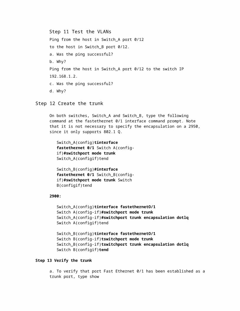
Step 11 Test the VLANs
Ping from the host in Switch_A port 0/12 to the host in
Switch_B port 0/12.
a. Was the ping successful?
b. Why?
Ping from the host in Switch_A port 0/12 to the switch IP 192.168.1.2.
c. Was the ping successful?
d. Why?
Step 12 Create the trunk
On both switches, Switch_A and Switch_B, type the following command at the fastethernet 0/1 interface command prompt. Note that it is not necessary to specify the encapsulation on a 2950, since it only supports 802.1 Q.
Switch_A(config)tinterface fastethernet 0/1 Switch A(config-if)#switchport mode trunk Switch_A(configif)tend
Switch_B(config)#interface fastethernet 0/1 Switch_B(config-if)#switchport mode trunk Switch B(configif)tend
2900:
Switch_A(config)tinterface fastethernetO/1 Switch A(config-if)#switchport mode trunk Switch_A(config-if)#switchport trunk encapsulation dotlq Switch A(configif)tend
Switch_B(config)tinterface fastethernetO/1 Switch B(config-if)tswitchport mode trunk Switch_B(config-if)tswitchport trunk encapsulation dotlq Switch B(configif)tend
Step 13 Verify the trunk
a. To verify that port Fast Ethernet 0/1 has been established as a trunk port, type show interface fastethernet 0/1 switchport at the Privileged EXEC mode prompt.
b. What type of trunking encapsulation is shown on the output results?
C. According to the Output With show interface fastethernet 0/1 switchport on Switch_B, is there a difference from the Administrative Trunking Encapsulation from the Operational Trunking Encapsulation?
d. On the fragment "Trunking VLANs Enable" from the output, what does the word "ALL" mean?

e. What would happen if the two ports of the trunk were using different encapsulation?
f. Explain
4 -8 CCNA 3: Switching Basics and Intermediate Routing v 3.1 -Lab 9.1.5b Copyright © 2003, Cisco Systems, Inc.
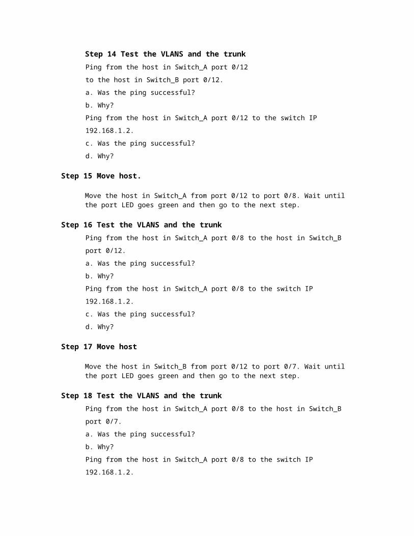
Step 14 Test the VLANS and the trunk Ping from the host in Switch_A port 0/12 to the host in
Switch_B port 0/12.
a. Was the ping successful?
b. Why?
Ping from the host in Switch_A port 0/12 to the switch IP 192.168.1.2.
c. Was the ping successful?
d. Why?
Step 15 Move host.
Move the host in Switch_A from port 0/12 to port 0/8. Wait until the port LED goes green and then go to the next step.
Step 16 Test the VLANS and the trunk Ping from the host in Switch_A port 0/8 to the host in Switch_B port 0/12.
a. Was the ping successful?
b. Why?
Ping from the host in Switch_A port 0/8 to the switch IP 192.168.1.2.
c. Was the ping successful?
d. Why?
Step 17 Move host
Move the host in Switch_B from port 0/12 to port 0/7. Wait until the port LED goes green and then go to the next step.
Step 18 Test the VLANS and the trunk Ping from the host in Switch_A port 0/8 to the host in Switch_B port 0/7.
a. Was the ping successful?
b. Why?
Ping from the host in Switch_A port 0/8 to the switch IP 192.168.1.2.
c. Was the ping successful?
d. Why?
Step 19 Move hosts
Move the host in Switch_A from port 0/8 to port 0/2. Wait until the port LED goes green and then go to the next step.
Step 20 Test the VLANS and the trunk
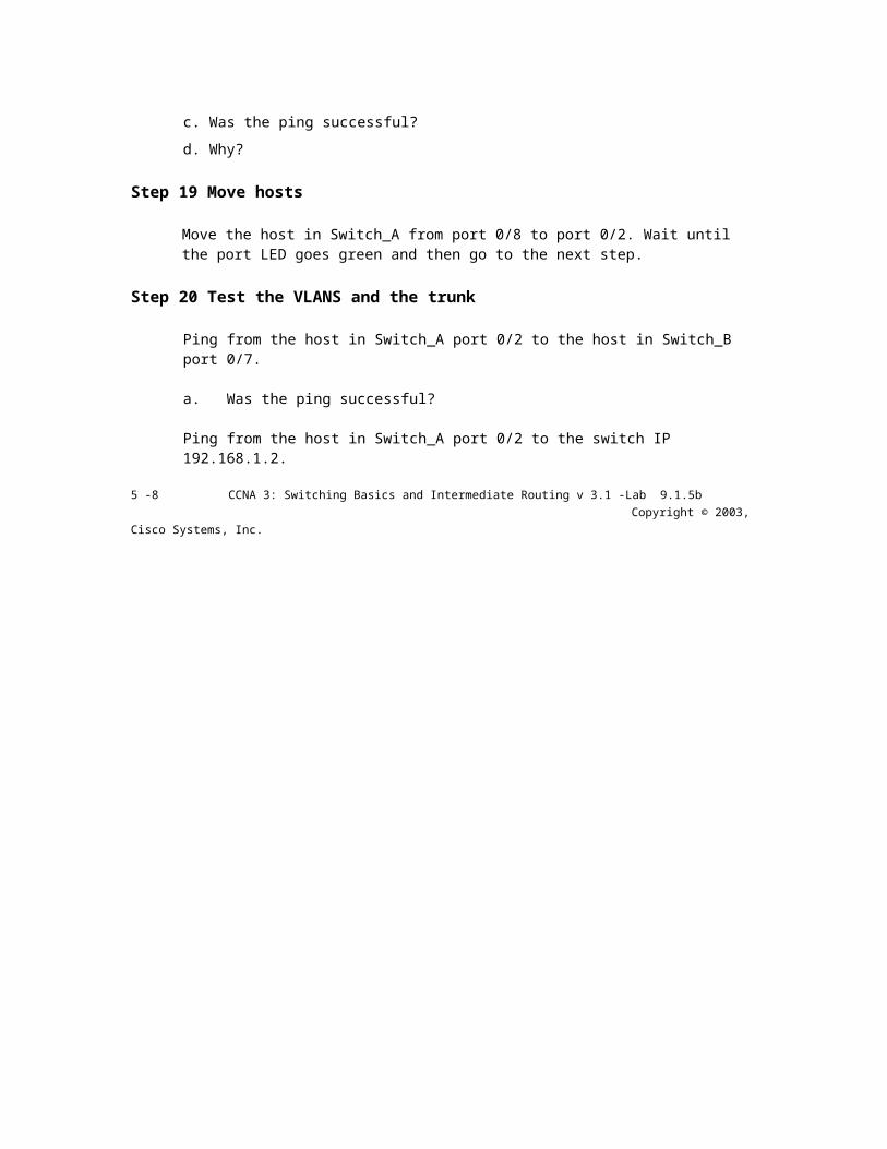
Ping from the host in Switch_A port 0/2 to the host in Switch_B port 0/7.
a. Was the ping successful?
Ping from the host in Switch_A port 0/2 to the switch IP 192.168.1.2.
5 -8 CCNA 3: Switching Basics and Intermediate Routing v 3.1 -Lab 9.1.5b Copyright © 2003, Cisco Systems, Inc.
b. Was the ping successful?
c. Why?
Step 21 Move host
Move the host in Switch_B from port 0/7 to port 0/3. Wait until the port LED goes green and then go to the next step.
Step 22 Test the VLANS and the trunk Ping from the host in Switch_A port 0/2 to the host in Switch_B port 0/3.
a. Was the ping successful?
b. Why?
Ping from the host in Switch_B port 0/3 to the switch IP 192.168.1.2.
c. Was the ping successful?
d. Why?
Ping from the host in Switch_B port 0/3 to the switch IP 192.168.1.3.
e. Was the ping successful?
f. Why?


g. What conclusions can be drawn from the testing that was just performed in regards to VLAN membership and VLANs across a trunk?
Once the steps are complete, logoff by typing exit, and turn all the devices off. Then remove and store the cables and adapter.
6 -8 CCNA 3: Switching Basics and Intermediate Routing v 3.1 -Lab 9.1.5b Copyright © 2003, Cisco Systems, Inc.

Erasing and Reloading the Switch
For the majority of the labs in CCNA 3 and CCNA 4 it is necessary to start with an unconfigured switch. Use of a switch with an existing configuration may produce unpredictable results. These instructions allow preparation of the switch prior to performing the lab so previous configuration options do not interfere. The following is the procedure for clearing out previous configurations and starting with an unconfigured switch. Instructions are provided for the 2900, 2950, and 1900 Series switches.
2900 and 2950 Series Switches 1. Enter into the Privileged EXEC mode by typing enable.
Switch>enable
If prompted fora password, enter class, if that does not work, ask the instructor.
2. Remove the VLAN database information file.
Switch#delete flash:vlan.dat Delete filename [vlan.dat]?[Enter] Delete flash:vlan.dat? [confirm] [Enter]
If there was no VLAN file, this message is displayed.
%Error deleting flash:vlan.dat (No such file or directory)
3. Remove the switch startup configuration file from NVRAM.
Switch#erase startup-config
The responding line prompt will be:
Erasing the nvram filesystem will remove all files! Continue? [confirm]
Press Enter to confirm. The response should be:
Erase of nvram: complete
4. Check that VLAN information was deleted.
Verify that the VLAN configuration was deleted in Step 2 using the show vlan command. If previous VLAN configuration information (other than the default management VLAN 1) is still present it will be necessary to power cycle the switch (hardware restart) instead of issuing the reload command. To power cycle the switch, remove the power cord from the back of the switch or unplug it. Then plug it back in.

If the VLAN information was successfully deleted in Step 2, go to Step 5 and restart the switch using the reload command.
5. Software restart (using the reload command)
7 -8 CCNA 3: Switching Basics and Intermediate Routing v 3.1 -Lab 9.1.5b Copyright © 2003, Cisco Systems, Inc.
Note: This step is not necessary if the switch was restarted using the power cycle method.
a. At the Privileged EXEC mode enter the command reload.
Switch(config)#reload
The responding line prompt will be:
System configuration has been modified. Save? [yes/no]:
b. Type n and then press
Enter. The responding
line prompt will be:
Proceed with reload? [confirm] [Enter]
The first line of the response will be:
Reload requested by console.
After the switch has reloaded, the line prompt will be:
Would you like to enter the initial configuration dialog? [yes/no]:
c. Type n and then press
Enter. The responding
line prompt will be:
Press RETURN to get started! [Enter]
1900 Series Switches
1. Remove VLAN Trunking Protocol (VTP) information.
#delete vtp This command resets the switch with VTP parameters set to factory defaults. All other parameters will be unchanged.
Reset system with VTP parameters set to factory defaults, [Y]es or [N]o?
Enter y and press Enter.
2. Remove the switch startup configuration from NVRAM.
#delete nvram
This command resets the switch with factory defaults. All system parameters will revert to their default factory settings. All static and dynamic addresses will be removed.
Reset system with factory defaults, [Y]es or [N]o?
Enter y and press Enter.
8 -8 CCNA 3: Switching Basics and Intermediate Routing v 3.1 -Lab 9.1.5b Copyright © 2003, Cisco Systems, Inc.
Cisco Ststems
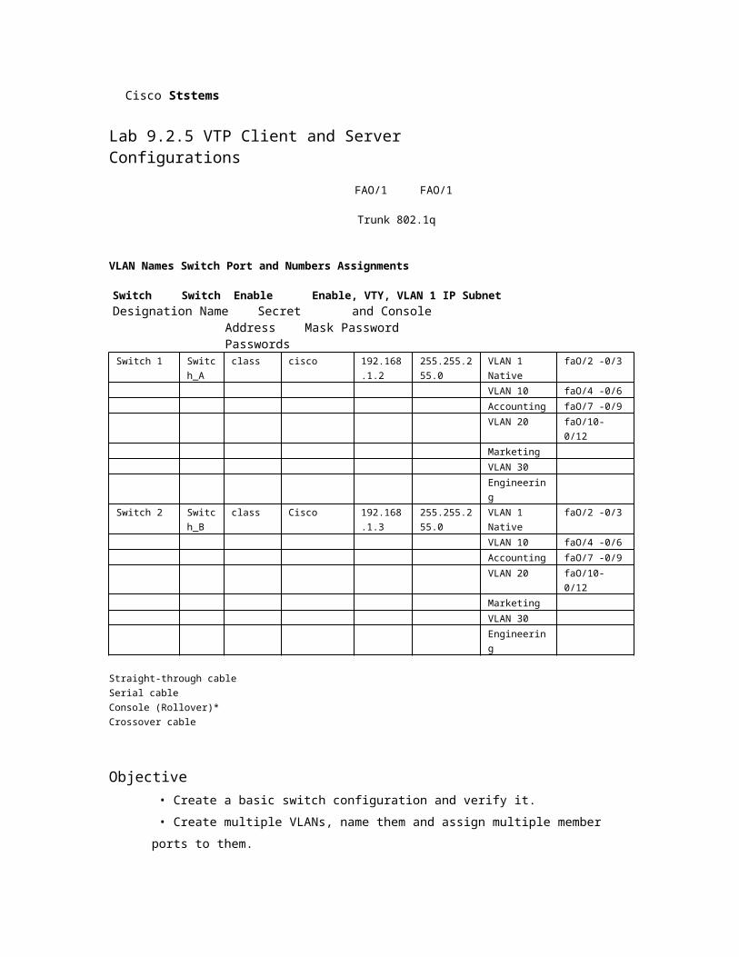
Lab 9.2.5 VTP Client and Server Configurations
FAO/1 FAO/1
Trunk 802.1q
VLAN Names Switch Port and Numbers Assignments
Switch Switch Enable Enable, VTY, VLAN 1 IP Subnet Designation Name Secret and Console Address Mask
Password Passwords Switch 1 Switch
_A class cisco 192.168.1
.2 255.255.255.0
VLAN 1 Native
faO/2 -0/3
VLAN 10 faO/4 -0/6 Accounting faO/7 -0/9 VLAN 20 faO/10-0/12 Marketing VLAN 30 Engineering
Switch 2 Switch_B
class Cisco 192.168.1.3
255.255.255.0
VLAN 1 Native
faO/2 -0/3
VLAN 10 faO/4 -0/6 Accounting faO/7 -0/9 VLAN 20 faO/10-0/12 Marketing VLAN 30 Engineering
Straight-through cable Serial cable Console (Rollover)* Crossover cable
Objective • Create a basic switch configuration and verify it.
• Create multiple VLANs, name them and assign multiple member ports to them.
• Configure the VTP protocol to establish Server and client switches.


• Create an 802.1q trunk line between the two switches to allow communication between paired VLANs.
• Then test the VLANs functionality by moving a workstation from one VLAN to another.
Background/Preparation
When managing a switch, the Management Domain is always VLAN 1. The Network Administrator's workstation must have access to a port in the VLAN 1 Management Domain. All ports are assigned to VLAN 1 by default.
Cable a network similar to the one of in diagram. The configuration output used in this lab is produced from a 2950 series switch. Any other switch used may produce different output. The following steps are to be executed on each switch unless specifically instructed otherwise.
Start a HyperTerminal session.
1 -8 CCNA 3: Switching Basics and Intermediate Routing v 3.1 -Lab 9.2.5 Copyright © 2003, Cisco Systems, Inc.

Note: Go to the erase and reload instructions at the end of this lab. Perform those steps on all switches in this lab assignment before continuing.
Step 1 Configure the switch
Configure the hostname, access, and command mode passwords, as well as the management LAN settings. These values are shown in the chart. If problems occur while performing this configuration, refer to the Basic Switch Configuration lab.
Step 2 Configure the hosts attached to the switch
Configure the IP address, mask, and default gateway on each host. Be sure to choose addresses that are on the same subnet as the switch.
Step 3 Verify connectivity
a. To verify that the host and switch are correctly configured, ping the switch from the hosts.
b. Were the pings successful?
c. If the answer is no, troubleshoot the host and switches configurations.
Step 4 Display the VLAN interface information
On Switch_A, type the command show vlan at the Privileged EXEC prompt as follows:
Switch_A#show vlan
Note: There should be an entry for VLAN 1 and the default VLANs (1002 +). If other VLANs appear, they could be deleted as instructed in Step 2 of the Erasing and Reloading instructions at the end of this lab or refer to the Lab Exercise: Deleting VLAN Configurations.
Step 5 Configure VTP

a. VLAN Trunking Protocol (VTP) needs to be configured on both switches. VTP is the protocol that will communicate information about which VLANs exist from one switch to another. If VTP did not provide this information, VLANs would have to be created on all switches individually.

b. By default, the Catalyst switch series are configured as VTP servers. In the event that the server services are turned off, use the following command to turn it back on:
Switch_A#vlan database Switch_A(vlan)#vtp server Switch_A(vlan)#vtp domain groupl Switch A(vlan)#exit
Step 6 Create and name three VLANs
Enter the following commands to create and name three VLANs:
Switch_A#vlan database Switch_A(vlan)#vlan 10 name Accounting Switch_A(vlan)#vlan 20 name Marketing Switch_A(vlan)#vlan 30 name Engineering Switch_A(vlan)#exit
Use the show vlan command to verify that the VLANs have been created correctly.
2 -8 CCNA 3: Switching Basics and Intermediate Routing v 3.1 -Lab 9.2.5 Copyright © 2003, Cisco Systems, Inc.

Step 7 Assign ports to VLAN 10
Assigning ports to VLANs must be done from the interface mode. Enter the following commands to add ports 0/4 to 0/6 to VLAN 10:
Switch_A#configure terminal Switch_A(config)#interface fastethernet 0/4 Switch_A(config-if)#switchport mode access Switch_A(config-if)#switchport access vlan 10 Switch_A(config-if)#interface fastethernet 0/5 Switch_A(config-if)#switchport mode access Switch_A(config-if)#switchport access vlan 10 Switch_A(config-if)#interface fastethernet 0/6 Switch_A(config-if)#switchport mode access Switch_A(config-if)#switchport access vlan 10 Switch_A(configif)#end
Step 8 Assign ports to VLAN 20
Enter the following commands to add ports 0/7 to 0/9 to VLAN 20:
Switch_A#configure terminal Switch_A(config)#interface fastethernet 0/7 Switch_A(config-if)#switchport mode access Switch_A(config-if)#switchport access vlan 20 Switch_A(config-if)#interface fastethernet 0/8 Switch_A(config-if)#switchport mode access Switch_A(config-if)#switchport access vlan 20 Switch_A(config-if)#interface fastethernet 0/9 Switch_A(config-if)#switchport mode access Switch_A(config-if)#switchport access vlan 20 Switch_A(configif)#end
Step 9 Assign ports to VLAN 30
Enter the following commands to add ports 0/10 to 0/12 to VLAN 30:
Switch_A#configure terminal Switch_A(config)#interface fastethernet 0/10 Switch_A(config-if)#switchport mode access Switch_A(config-if)#switchport access vlan 30 Switch_A(config-if)#interface fastethernet 0/11 Switch_A(config-if)#switchport mode access Switch_A(config-if)#switchport access vlan 30 Switch_A(config-if)#interface fastethernet 0/12 Switch_A(config-if)#switchport mode access Switch_A(config-if)#switchport access vlan 30 Switch_A(configif)#end

Step 10 Display the VLAN interface information
a. On Switch_A, type the command show vlan at the Privileged EXEC prompt as follows:
Switch A#show vlan
3 -8 CCNA 3: Switching Basics and Intermediate Routing v 3.1 -Lab 9.2.5 Copyright © 2003, Cisco Systems, Inc.

b. Are ports 0/10 through 0/12 assigned to VLAN 30?
Step 11 Configure VTP client
Enter the following commands to configure Switch_B to be a VTP client:
Switch_B#vlan database Switch_B(vlan)#vtp client Switch_B(vlan)#vtp domain groupl Switch_B(vlan)#exit
Step 12 Create the trunk
On both switches, Switch_A and Switch_B, type the following command at the fastethernet 0/1 interface command prompt. Note that it is not necessary to specify the encapsulation on a 2950, since it only supports 802.1 Q.
Switch_A(config)#interface fastethernet 0/1 Switch_A(config-if)#switchport mode trunk Switch_A(configif)#end
Switch_B(config)#interface fastethernet 0/1 Switch_B(config-if)#switchport mode trunk Switch_B(configif)#end
2900:
Switch_A(config)#interface fastethernetO/1 Switch_A(config-if)#switchport mode trunk Switch_A(config-if)#switchport trunk encapsulation dotlq Switch_A(configif)#end
Switch_B(config)#interface fastethernetO/1 Switch_B(config-if)#switchport mode trunk Switch_B(config-if)#switchport trunk encapsulation dotlq Switch_B(configif)#end
Step 13 Verify the trunk


a. To verify that port fastethernet 0/1 has been established as a trunk port, type show interface fastethernet 0/1 switchport at the Privileged EXEC mode prompt
b. What type of trunking encapsulation is shown on the output results?
Step 14 Display the VLAN interface information
a. On Switch_B, type the command show vlan at the Privileged EXEC prompt as follows:
Switch_B#show vlan
b. Do VLANs 10, 20, and 30 show without having to type them in?
c. Why did this happen?
4 -8 CCNA 3: Switching Basics and Intermediate Routing v 3.1 -Lab 9.2.5 Copyright © 2003, Cisco Systems, Inc.
Step 15 Assign ports to a VLAN 10
Although the VLAN definitions have migrated to Switch_B using VTP, it is still necessary to assign ports to these VLANs on Switch_B. Assigning ports to VLANs must be done from the interface mode. Enter the following commands to add ports 0/4 to 0/6 to VLAN 10.
Switch_B#configure terminal Switch_B(config)#interface fastethernet 0/4 Switch_B(config-if)#switchport mode access Switch_B(config-if)#switchport access vlan 10 Switch_B(config-if)#interface fastethernet 0/5 Switch_B(config-if)#switchport mode access Switch_B(config-if)#switchport access vlan 10 Switch_B(config-if)#interface fastethernet 0/6 Switch_B(config-if)#switchport mode access Switch_B(config-if)#switchport access vlan 10 Switch_B(configif)#end
Step 16 Assign ports to VLAN 20
Enter the following commands to add ports 0/7 to 0/9 to VLAN 20:
Switch_B#configure terminal Switch_B(config)#interface fastethernet 0/7 Switch_B(config-if)#switchport mode access Switch_B(config-if)#switchport access vlan 20 Switch_B(config-if)#interface fastethernet 0/8 Switch_B(config-if)#switchport mode access Switch_B(config-if)#switchport access vlan 20 Switch_B(config-if)#interface fastethernet 0/9 Switch_B(config-if)#switchport mode access Switch_B(config-if)#switchport access vlan 20 Switch_B(configif)#end
Step 17 Assign ports to VLAN 30
Enter the following commands to add ports 0/10 to 0/12 to VLAN 30:
Switch_B#configure terminal Switch_B(config)#interface fastethernet 0/10 Switch_B(config-if)#switchport mode access Switch_B(config-if)#switchport access vlan 30 Switch_B(config-if)#interface fastethernet 0/11 Switch_B(config-if)#switchport mode access Switch_B(config-if)#switchport access vlan 30 Switch_B(config-if)#interface fastethernet 0/12 Switch_B(config-if)#switchport mode
access Switch_B(config-if)#switchport access vlan 30 Switch_B(configif)#end
Step 18 Display the VLAN interface information
a. On Switch_B, type the command show vlan at the Privileged EXEC prompt as follows:
Switch B#show vlan
5 -8 CCNA 3: Switching Basics and Intermediate Routing v 3.1 -Lab 9.2.5 Copyright © 2003, Cisco Systems, Inc.

b. Are ports 0/10 through 0/12 assigned to VLAN 30?
Step 19 Test the VLANS and the trunk Ping from the host in Switch_A port 0/12 to the host in
Switch_B port 0/12.
a. Was the ping successful?
b. Why?
Ping from the host in Switch_A port 0/12 to the switch IP 192.168.1.2.
c. Was the ping successful?
d. Why?
Step 20 Move hosts
Move the host in Switch_A from port 0/12 to port 0/8. Wait until the port LED goes green and then go to the next step.
Step 21 Test the VLANS and the trunk
Ping from the host in Switch_A port 0/8 to the host in Switch_B port 0/12.
a. Was the ping successful?
b. Why?
Ping from the host in Switch_A port 0/8 to the switch IP 192.168.1.2.
c. Was the ping successful?
d. Why?
Once the steps are complete, logoff by typing exit, and turn all the devices off. Then remove and store the cables and adapter.
6 -8 CCNA 3: Switching Basics and Intermediate Routing v 3.1 -Lab 9.2.5 Copyright © 2003, Cisco Systems, Inc.

Erasing and Reloading the Switch
For the majority of the labs in CCNA 3 and CCNA 4 it is necessary to start with an unconfigured switch. Use of a switch with an existing configuration may produce unpredictable results. These instructions allow preparation of the switch prior to performing the lab so previous configuration options do not interfere. The following is the procedure for clearing out previous configurations and starting with an unconfigured switch. Instructions are provided for the 2900, 2950, and 1900 Series switches.
2900 and 2950 Series Switches
1. Enter into the Privileged EXEC mode by typing enable.
Switch>enable
If prompted for a password, enter class, if that does not work, ask the instructor.
2. Remove the VLAN database information file.
Switch#delete flash:vlan.dat Delete filename [vlan.dat]?[Enter] Delete flash:vlan.dat? [confirm] [Enter]
If there was no VLAN file, this message is displayed.
%Error deleting flash:vlan.dat (No such file or directory)
3. Remove the switch startup configuration file
from NVRAM. Switch#erase startup-config
The responding line prompt will be:
Erasing the nvram filesystem will remove all files! Continue? [confirm]
Press Enter to confirm. The response should be:
Erase of nvram: complete
4. Check that VLAN information was deleted.
Verify that the VLAN configuration was deleted in Step 2 using the show vlan command. If previous VLAN configuration information (other than the default

management VLAN 1) is still present it will be necessary to power cycle the switch (hardware restart) instead of issuing the reload command. To power cycle the switch, remove the power cord from the back of the switch or unplug it. Then plug it back in.
If the VLAN information was successfully deleted in Step 2, go to Step 5 and restart the switch using the reload command.
5. Software restart (using the reload command)
7 -8 CCNA 3: Switching Basics and Intermediate Routing v 3.1 -Lab 9.2.5 Copyright © 2003, Cisco Systems, Inc.

Note: This step is not necessary if the switch was restarted using the power cycle method.
a. At the Privileged EXEC mode enter the command reload.
Switch(config)#reload
The responding line
prompt will be:
System configuration has been modified. Save? [yes/no]:
b. Type n and then press
Enter. The responding
line prompt will be:
Proceed with reload? [confirm]
[Enter] The first line of the response will
be:
Reload requested by console.
After the switch has reloaded, the line prompt will be:
Would you like to enter the initial configuration dialog?
[yes/no]:
c. Type n and then press
Enter. The responding
line prompt will be:
Press RETURN to get started! [Enter]
1900 Series Switches
1. Remove VLAN Trunking Protocol (VTP) information.

ttdelete vtp This command resets the switch with VTP parameters set to factory defaults. All other parameters will be unchanged.
Reset system with VTP parameters set to factory defaults, [Y]es or [N]o?
Enter y and press Enter.
2. Remove the switch startup configuration from NVRAM.
#delete nvram
This command resets the switch with factory defaults. All system parameters will revert to their default factory settings. All static and dynamic addresses will be removed.
Reset system with factory defaults,
[Y]es or [N]o? Enter y and press Enter.
8 -8 CCNA 3: Switching Basics and Intermediate Routing v 3.1 -Lab 9.2.5 Copyright © 2003, Cisco Systems, Inc.
Cisco Systems
Lab 9.3.6 Configuring Inter-VLAN Routing
Switch Switch Enable Enable, VTY, VLAN 1 IP Subnet VLAN Names Switch Port Designation Name Secret and Console Address Mask and Numbers Assignments
Password Passwords
Switch 1 Switah_A
class cisco 192.168.1.2
255.255.255.0
VLAN 1 Native VLAN 10 Sales VLAN 20 Support
faO/1 -0/4 faO/5 -0/8 faO/9-0/12
Straight-through cable
Serial cable
Console (Rollover)
Crossover cable
Objective • Create a basic switch configuration and verify it.
• Create multiple VLANs, name them and assign multiple member ports to them.
• Create a basic configuration on a router.
• Create an 802.1 q trunk line between the switch and router to allow communication between VLANs.
• Test the routing functionality.
Background/Preparation
When managing a switch, the Management Domain is always VLAN 1. The Network Administrator's workstation must have access to a port in the VLAN 1 Management Domain. All ports are assigned to VLAN 1 by default. This lab will also help demonstrate how VLANs can be used to separate traffic and reduce broadcast domains.
Cable a network similar to the one in the diagram. The configuration output used in this lab is produced from a 2950 series switch. Any other switch used may produce different output. The following steps are to be executed on each switch unless specifically instructed otherwise. Instructions are also provided for the 2900 and 1900 Series switches. The 1900 Series switch initially displays a User Interface Menu. Select the "Command Line" option from the menu to perform the steps for this lab.

1 -7 CCNA 3: Switching Basics and Intermediate Routing v 3.1 -Lab 9.3.6 Copyright © 2003, Cisco Systems, Inc.
Note: The router used must have a Fast Ethernet interface in order to support trunking and inter-VLAN routing. The 2500 series router cannot be used for this lab.
Start a HyperTerminal session.
Note: Go to the erase and reload instructions at the end of this lab. Perform those steps on all switches in this lab assignment before continuing.
Step 1 Configure the switch
Configure the hostname, access, and command mode passwords, as well as the management LAN settings. These values are shown in the chart. If problems occur while performing this configuration, refer to the Basic Switch Configuration lab.
Step 2 Configure the hosts attached to the switch Configure the hosts using the following information.
a. For the host in port 0/5:
IP address 192.168.5.2
Subnet mask 255.255.255.0
Default gateway 192.168.5.1
b. For the host in port 0/9:
IP address 192.168.7.2
Subnet mask 255.255.255.0
Default gateway 192.168.7.1
Step 3 Verify connectivity Check to see if the hosts can ping the switch.
a. Ping the switch IP address from the hosts.
b. Were the pings successful?
c. Why or why not?
Step 4 Create and name two VLANs
Enter the following commands to create and name two VLANs:
Switch_A#vlan database Switch A(vlan)ivlan 10 name Sales Switch_A(vlan)#vlan 20 name Support Switch_A(vlan)#exit
1900:
Switch A#config terminal Switch A(config)#vlan 10 name Sales Switch_A(config)#vlan 20 name Support Switch A(config)#exit
Step 5 Assign ports to VLAN 10
Assigning ports to VLANs must be done from the interface mode. Enter the following commands to add ports 0/5 to 0/8 to VLAN 10:
2 -7 CCNA 3: Switching Basics and Intermediate Routing v 3.1 -Lab 9.3.6 Copyright © 2003, Cisco Systems, Inc.
Switch_A#configure terminal Switch A(config)#interface fastethernet 0/5 Switch_A(config-if)#switchport mode access Switch A(config-if)#switchport access vlan 10 Switch_A(config-if)#interface fastethernet 0/6 Switch_A(config-if)#switchport mode access Switch A(config-if)#switchport access vlan 10 Switch_A(config-if)#interface fastethernet 0/7 Switch A(config-if)#switchport mode access Switch_A(config-if)#switchport access vlan 10 Switch_A(config-if)#interface fastethernet 0/8 Switch A(config-if)#switchport mode access Switch_A(config-if)#switchport access vlan 10 Switch A(configif)tend
1900:
Switch A#config terminal Switch_A(config)#interface ethernet 0/5 Switch_A(config-if)vlan static 10 Switch A(config-if)#interface ethernet 0/6 Switch_A(config-if)vlan static 10 Switch A(config-if)#interface ethernet 0/7 Switch_A(config-if)vlan static 10 Switch_A(config-if)#interface ethernet 0/8 Switch A(config-if)vlan static 10 Switch_A(configif)tend
Step 6 Assign ports to VLAN 20
Enter the following commands to add ports 0/9 to 0/12 to VLAN 20:
Switch A#configure terminal Switch_A(config)#interface fastethernet 0/9 Switch A(config-if)#switchport mode access Switch_A(config-if)#switchport access vlan 20 Switch_A(config-if)#interface fastethernet 0/10 Switch_A(config-if)#switchport mode access Switch A(config-if)#switchport access vlan 20 Switch_A(config-if)#interface fastethernet 0/11 Switch_A(config-if)#switchport mode access Switch A(config-if)#switchport access vlan 20 Switch_A(config-if)tinterface fastethernetO/12 Switch A(config-if)#switchport mode access Switch A(config-if)#switchport access vlan 20 Switch_A(configif)tend
1900:
Switch_A#config terminal
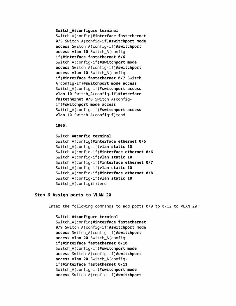
Switch_A(config)#interface ethernet 0/9 Switch_A(config-if)vlan static 20 Switch_A(config-if)#interface ethernet 0/10 Switch A(config-if)vlan static 20 Switch_A(config-if)#interface ethernet 0/11 Switch A(config-if)vlan static 20 Switch_A(config-if)#interface ethernet 0/12
3 -7 CCNA 3: Switching Basics and Intermediate Routing v 3.1 -Lab 9.3.6 Copyright © 2003, Cisco Systems, Inc.
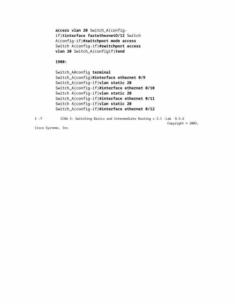
Switch A(config-if)vlan static 20 Switch_A(configif)tend
Step 7 Display the VLAN interface information
a. On Switch_A, type the command show vlan at the Privileged EXEC prompt as follows:
Switch A#show vlan
b. Are ports assigned correctly?
Step 8 Create the trunk
On Switch_A, type the following commands at the Fast Ethernet 0/1 interface command prompt. Note that Ethernet 0/1 and the other access ports on a 1900 switch only support 10 Mbps Ethernet and cannot be used as trunk ports. The trunk ports (if present) on a 24-port 1900 are typically Fast Ethernet 0/26 and 0/27.
Switch_A(config)#interface fastethernetO/1 Switch_A(config-if)#switchport mode trunk Switch A(configif)tend
2900:
Switch_A(config)tinterface fastethernetO/1 Switch A(config-if)#switchport mode trunk Switch_A(config-if)#switchport trunk encapsulation dotlq Switch_A(configif)tend
1900:
Switch_A#config terminal Switch_A(config)tinterface fastethernetO/26 Switch A(config-if)ttrunk on
Step 9 Configure the router


a. Configure the router with the following data. Note that in order to support trunking and inter-VLAN routing, the router must have a Fast Ethernet interface.
Hostname is Router_A
Console, VTY, and enable passwords are Cisco.
Enable secret password is class.
b. Then configure the Fast Ethernet interface using the following commands:
Note: If working with a 1900 switch, replace the "dotlq" encapsulation with "isl" in the following router configuration commands.
Router A(config)tinterface fastethernet 0/0 Router_A(config-if)tno shutdown Router_A(config-if)tinterface fastethernet 0/0.1 Router A ( config-subif)tencapsulation dotlq 1 Router~A(config-subif)tip address 192.168.1.1 255.255.255.0 Router_A(config-if)tinterface fastethernet 0/0.2 Router_A(config-subif)tencapsulation dotlq 10 Router~A(config-subif)tip address 192.168.5.1 255.255.255.0 Router_A(config-if)tinterface fastethernet 0/0.3 Router_A(config-subif)tencapsulation dotlq 20
4 -7 CCNA 3: Switching Basics and Intermediate Routing v 3.1 -Lab 9.3.6 Copyright © 2003, Cisco Systems, Inc.

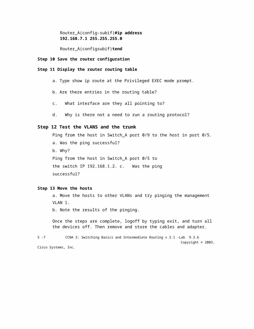
Router_A(config-subif)#ip address 192.168.7.1 255.255.255.0
Router_A(configsubif)tend
Step 10 Save the router configuration
Step 11 Display the router routing table
a. Type show ip route at the Privileged EXEC mode prompt.
b. Are there entries in the routing table?
c. What interface are they all pointing to?
d. Why is there not a need to run a routing protocol?
Step 12 Test the VLANS and the trunk Ping from the host in Switch_A port 0/9 to the host in port 0/5.
a. Was the ping successful?
b. Why?
Ping from the host in Switch_A port 0/5 to the switch IP
192.168.1.2. c. Was the ping successful?
Step 13 Move the hosts a. Move the hosts to other VLANs and try pinging the management VLAN 1.
b. Note the results of the pinging.
Once the steps are complete, logoff by typing exit, and turn all the devices off. Then remove and store the cables and adapter.
5 -7 CCNA 3: Switching Basics and Intermediate Routing v 3.1 -Lab 9.3.6 Copyright © 2003, Cisco Systems, Inc.
Erasing and Reloading the Switch
For the majority of the labs in CCNA 3 and CCNA 4 it is necessary to start with an unconfigured switch. Use of a switch with an existing configuration may produce unpredictable results. These instructions allow preparation of the switch prior to performing the lab so previous configuration options do not interfere. The following is the procedure for clearing out previous configurations and starting with an unconfigured switch. Instructions are provided for the 2900, 2950, and 1900 Series switches.
2900 and 2950 Series Switches 1. Enter into the Privileged EXEC mode by typing enable.
Switch>enable
If prompted fora password, enter class, if that does not work, ask the instructor.
2. Remove the VLAN database information file.
Switch#delete flash:vlan.dat Delete filename [vlan.dat]?[Enter] Delete flash:vlan.dat? [confirm] [Enter]
If there was no VLAN file, this message is displayed.
%Error deleting flash:vlan.dat (No such file or directory)
3. Remove the switch startup configuration file from NVRAM.
Switch#erase startup-config
The responding line prompt will be:
Erasing the nvram filesystem will remove all files! Continue? [confirm]
Press Enter to confirm. The response should be:
Erase of nvram: complete
4. Check that VLAN information was deleted.
Verify that the VLAN configuration was deleted in Step 2 using the show vlan command. If previous VLAN configuration information (other than the default management VLAN 1) is still present it will be necessary to power cycle the switch (hardware restart) instead of issuing the reload command. To power cycle the switch, remove the power cord from the back of the switch or unplug it. Then plug it back in.

If the VLAN information was successfully deleted in Step 2, go to Step 5 and restart the switch using the reload command.
5. Software restart (using the reload command)
6 -7 CCNA 3: Switching Basics and Intermediate Routing v 3.1 -Lab 9.3.6 Copyright © 2003, Cisco Systems, Inc.

Note: This step is not necessary if the switch was restarted using the power cycle method.
a. At the Privileged EXEC mode enter the command reload.
Switch(config)#reload
The responding line prompt will be:
System configuration has been modified. Save? [yes/no]:
b. Type n and then press
Enter. The responding
line prompt will be:
Proceed with reload? [confirm] [Enter]
The first line of the response will be:
Reload requested by console.
After the switch has reloaded, the line prompt will be:
Would you like to enter the initial configuration dialog? [yes/no]:
c. Type n and then press
Enter. The responding
line prompt will be:
Press RETURN to get started! [Enter]
1900 Series Switches
1. Remove VLAN Trunking Protocol (VTP) information.
#delete vtp This command resets the switch with VTP parameters set to factory defaults. All other parameters will be unchanged.
Reset system with VTP parameters set to factory defaults, [Y]es or [N]o?
Enter y and press Enter.
2. Remove the switch startup configuration from NVRAM.
#delete nvram

This command resets the switch with factory defaults. All system parameters will revert to their default factory settings. All static and dynamic addresses will be removed.
Reset system with factory defaults, [Y]es
or [N]o? Enter y and press Enter.
7 -7 CCNA 3: Switching Basics and Intermediate Routing v 3.1 -Lab 9.3.6 Copyright © 2003, Cisco Systems, Inc.