Lab 8: VLANs - site.iugaza.edu.pssite.iugaza.edu.ps/eelradie/files/2015/04/Lab8_VLANS.pdf · Lab 8:...
13
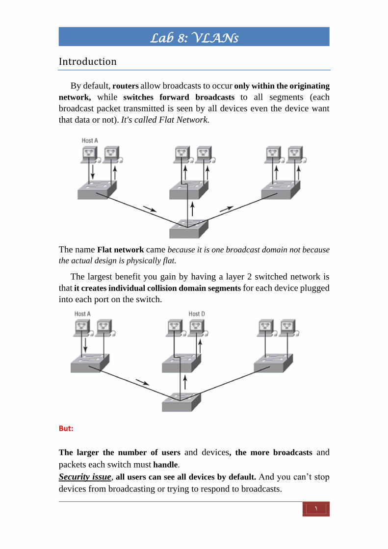
1 Lab 8: VLANs Introduction By default, routers allow broadcasts to occur only within the originating network, while switches forward broadcasts to all segments (each broadcast packet transmitted is seen by all devices even the device want that data or not). It's called Flat Network. The name Flat network came because it is one broadcast domain not because the actual design is physically flat. The largest benefit you gain by having a layer 2 switched network is that it creates individual collision domain segments for each device plugged into each port on the switch. But: The larger the number of users and devices, the more broadcasts and packets each switch must handle. Security issue, all users can see all devices by default. And you can’t stop devices from broadcasting or trying to respond to broadcasts.
Transcript of Lab 8: VLANs - site.iugaza.edu.pssite.iugaza.edu.ps/eelradie/files/2015/04/Lab8_VLANS.pdf · Lab 8:...
1
Lab 8: VLANs
Introduction
By default, routers allow broadcasts to occur only within the originating
network, while switches forward broadcasts to all segments (each
broadcast packet transmitted is seen by all devices even the device want
that data or not). It's called Flat Network.
The name Flat network came because it is one broadcast domain not because
the actual design is physically flat.
The largest benefit you gain by having a layer 2 switched network is
that it creates individual collision domain segments for each device plugged
into each port on the switch.
But:
The larger the number of users and devices, the more broadcasts and
packets each switch must handle.
Security issue, all users can see all devices by default. And you can’t stop
devices from broadcasting or trying to respond to broadcasts.

2
Lab 8: VLANs
Solution?
Using: virtual LAN (VLAN)
By just configuring a port into the appropriate VLAN. You can stop
users outside of the VLAN from communicating with user within
VLAN, more security .
Logical grouping of users by function, VLANs can be considered
independent from their physical or geographic locations (flexibility).
VLANs increase the number of broadcast domains while decreasing
their size.
"The days when anyone could just plug their workstations into any switch
port and gain access to network resources are history because now you get
to control each port, plus whatever resources that port can access."
3.1.4.1

3
Lab 8: VLANs
What happens if the switch for Sales -for example- is full and we need to
add another user to the Sales LAN? Or, what do we do if there’s no more
physical space where the Sales team is located for this new employee?
Ok then, why would we need a router since we can break broadcast domains
by L2 switches?!
To communicate to a node or host on a different VLAN we need a router,
straightforward! As it's a real LANs.
3.1.4.2

4
Lab 8: VLANs
Identifying VLANs
A switch port can belong to only one VLAN if it is an access port or all
VLANs if it is a trunk.
Trunk link
Frame tagging
Trunk link can hold frames from all VLANs, so we need to tag each frame
to know what VLAN it belongs to.
Frame tagging: each frame must be first tagged with the VLAN ID before
forwarded into a trunk link.
Frame tagging can be done by either :
Inter-Switch Link (ISL)
A way of explicitly tagging VLAN information onto an Ethernet
frame. This tagging information allows VLANs to be multiplexed
over a trunk link through an external encapsulation method. Which
allows the switch to identify the VLAN membership of a frame over
the trunked link.
Proprietary to Cisco switches.
Access links

5
Lab 8: VLANs
IEEE 802.1Q
Created by the IEEE as a standard method of frame tagging, IEEE
802.1Q actually inserts a field into the frame to identify the VLAN.
Note: If you’re trunking between a Cisco switched link and a different
brand of switch, you’ve got to use 802.1Q for the trunk to work.
Practical Part 1
1. Connect the following topology on Packet Tracer, and don't forget IPs
2. Try pinging devices from each other.
3. Save your work, copy the file for part2.
4. Now let's configure VLANs: Engineers, ITs, and Mangers on switch 0 and 1.

6
Lab 8: VLANs
Switch 0:
1. Enter global conf. mode (managed switch).
2. Start creating VLANs by the following syntax :
Switch(config)#vlan n
Switch(config-vlan)#name "naaaame "
Where n is VLAN id that range from 1-1005 but
ID 1 :Default VLAN
IDs 1002 through 1005 are reserved for Token Ring and FDDI VLANs
For our switch:
Switch(config)#vlan 2
Switch(config-vlan)#name IT
Switch(config-vlan)#vlan 3
Switch(config-vlan)#name ENG
Switch(config-vlan)#vlan 4
Switch(config-vlan)#name managers
** from privileged mode : show vlan
3. Now start adding interfaces to VLANs
For example,
Switch>en
Switch#conf t
Switch(config)#int fa0/1
Switch(config-if)#switchport mode access
Switch(config-if)#switchport access vlan 3
Repeat that for all interfaces connected to the devices.
4. Configuring trunk port.
Ports that connect switch are configured a little bit different:

7
Lab 8: VLANs
Switch(config-if)#int fa0/4
Switch(config-if)#switchport mode trunk
Repeat same steps on switch 1
Now try pinging, what did you notice?
For now, you are good to go! But notice that we did some redundant job over
the switches! Which is the creation on VLANs.
So, we will introduce VLAN Trunking Protocol (VTP).
What if we delete a VLAN?! VLAN Trunking Protocol (VTP)
The basic goals of VLAN Trunking Protocol (VTP) are to manage all configured
VLANs across a switched internetwork and to maintain consistency throughout
that network.
VTP allows a network manager to configure a switch so that it will propagate
VLAN configurations to other switches in the network. The switch can be
configured in the role of a VTP server or a VTP client.
VTP allows you to add, delete, and rename VLANs—information that is then
propagated to all other switches in the VTP domain. Plug and Play VLAN
adding.
VTP Components
VTP Domain
Consists of one or more interconnected switches. All switches in a domain
share VLAN configuration details using VTP advertisements.
VTP Advertisements
VTP uses a hierarchy of advertisements to distribute and synchronize
VLAN configurations across the network.

8
Lab 8: VLANs
VTP Modes
A switch can be configured in one of three modes: server, client, or
transparent.
VTP Server
VTP servers advertise the VTP domain VLAN information to other VTP-
enabled switches in the same VTP domain. VTP servers store the VLAN
information for the entire domain in NVRAM. The server is where VLAN
can created, deleted, or renamed for the domain.
VTP Client
VTP clients function the same way as VTP servers, but you cannot create,
change, or delete VLANs on a VTP client. A VTP client only stores the
VLAN information for the entire domain while the switch is on. A switch
reset deletes the VLAN information. You must configure VTP client mode
on a switch.
VTP Transparent
Transparent switches forward VTP advertisements to VTP clients and VTP
servers. Transparent switches do not participate in VTP. VLANs that are
created, renamed, or deleted on transparent switches are local to that switch
only.
VTP Revision Number
The configuration revision number is a 32-bit number that indicates the
level of revision for a VTP frame. The default configuration number for a
switch is zero. Each time a VLAN is added or removed, the configuration
revision number is incremented. The switch with higher Revision Number
becomes server!
You should know these three requirements for VTP to communicate
VLAN information between switches: • The VTP management domain name of both switches must be set the same.
• One of the switches has to be configured as a VTP server.
• No router is necessary.
Simply: VTP server creates, Clients follows.

9
Lab 8: VLANs
Configuration
To change status (by default all switches are servers)
Switch(config)# vtp mode server\client\transparent
To change domain name
Switch(config)# vtp domain domain-name
And to check changes use
Switch# show vtp status
And that's it
Remember you still have to add interfaces manually VTP only helps you
creating, deleting or renaming VLSNs!
Practical Part 2
Try using VTP on the topology above
Big problem!

11
Lab 8: VLANs
Configuring Inter-VLAN Routing
As we noticed form practical part1, we cannot ping devices on different
VLANs or by other word, we don't have connectivity over them!
The solution is to add a router so it can route between these VLANs.
By default, only hosts that are members of the same VLAN can communicate.
To change this and allow inter-VLAN communication, you need a router
or a layer 3 switch.
This can be achieved like this:
But notice that we lost two interfaces of the router! What if we have 30
VLANs! So we use what is called Router on a stick!

11
Lab 8: VLANs
To support ISL or 802.1Q routing on a Fast Ethernet interface, the router’s
interface is divided into logical interfaces—one for each VLAN. These are
called subinterfaces.
It’s really important that you understand that each VLAN is a separate subnet.
True, I know—they don’t have to be. But it really is a good idea to configure
your VLANs as separate subnets, so just do that.
Practical part 3
Let us now try to route between our VLANs: follow the steps:
1. Add a router to any switch and configure the switch port as trunk.
Switch(config)#int fa0/6 Switch(config-if)#switchport mode trunk
2. Subnet your topology in a consistent way with your VLANs :
You can use normal or VLSM subnetting, for simplicity we will use
the first one: 2bits to have 4 nets (Don't forget to set Default Gateway
for PCs)

12
Lab 8: VLANs
Subnet Net ID Mask
Engs 192.168.1.0 255.255.255.192
ITs 192.168.1.64 255.255.255.192
Managers 192.168.1.128 255.255.255.192
1. Turn on the router interface and start subinterfacing the interface!
Router>en
Router#conf t
Router(config)#int fa0/0.3(any number, try to put it the same as VLAN ID)
Router(config-subif)#encapsulation dot1Q ?
<1-1115 > IEEE 802.1Q VLAN ID
Router(config-subif)#encapsulation dot1Q 3(vlan id for engineers)
Router(config-subif)#ip address 192.168.1.1 255.255.255.192(ip and mask)
Same work for vlan2(IT) and 4(Managers).
Router(config-subif)#int fa0/0.2
Router(config-subif)#encapsulation dot1Q 2
Router(config-subif)#ip address 192.168.1.65 255.255.255.192
Router(config-subif)#int fa0/0.4

13
Lab 8: VLANs
Router(config-subif)#encapsulation dot1Q 4
Router(config-subif)#ip address 192.168.1.129 255.255.255.192
And don't forget to turn on the mother interface :D
Router(config)#int fa0/0
Router(config-if)#no shutdown
Now try pinging PCs in different VLANs traceroute it, too.
Very important lab