Lab 6 Sample Manual
28
Robert W. Heath Jr., Ph.D., P.E. DIGITAL COMMUNICATIONS PHYSICAL LAYER EXPLORATION LAB USING THE NI USRP ™ PLATFORM For Evaluation Only Lab 6 Sample
description
NI Digital communications sample lab
Transcript of Lab 6 Sample Manual

Robert W. Heath Jr., Ph.D., P.E.
DIGITAL COMMUNICATIONS
PHYSICAL LAYER EXPLORATION LAB USING THE NI USRP™ PLATFORM
03014_Cover.pdf 1 10/20/11 11:30 AM
For Evaluation Only Lab 6 Sample

For Evaluation Only Lab 6 Sample
�
�
“book” — 2011/9/29 — 15:18 — page i — #1�
�
�
�
�
�
Digital WirelessCommunication
Physical Layer Exploration Lab
Using the NI USRP
Student Lab Manual
Robert W. Heath Jr.
For Evaluation Only Lab 6 Sample

�
�
“book” — 2011/9/29 — 15:18 — page ii — #2�
�
�
�
�
�
ISBN-10: 1-934891-18-5ISBN-13: 978-1-934891-18-6
10 9 8 7 6 5 4 3 2
Publisher: Tom RobbinsGeneral Manager: Erik LutherTechnical Oversight: Sam ShearmanMarketing Manager: Amee ChristianDevelopment Editor: Catherine PeacockCompositor: Paul Mailhot, PreTeX Inc.
c©2012 National Technology and Science Press.
All rights reserved. Neither this book, nor any portion of it, may be copied or reproduced in anyform or by any means without written permission of the publisher.
NTS Press respects the intellectual property of others, and we ask our readers to do the same.This book is protected by copyright and other intellectual property laws. Where the softwarereferred to in this book may be used to reproduce software or other materials belonging to others,you should use such software only to reproduce materials that you may reproduce in accordancewith the terms of any applicable license or other legal restriction.
LabVIEW, USRP, Universal Software Radio Peripheral, and National Instruments are trademarksof National Instruments.
All other trademarks or product names are the property of their respective owners.
Additional Disclaimers:
The reader assumes all risk of use of this book and of all information, theories, and programscontained or described in it. This book may contain technical inaccuracies, typographicalerrors, other errors and omissions, and out-of-date information. Neither the author nor thepublisher assumes any responsibility or liability for any errors or omissions of any kind, toupdate any information, or for any infringement of any patent or other intellectual propertyright.
Neither the author nor the publisher makes any warranties of any kind, including withoutlimitation any warranty as to the sufficiency of the book or of any information, theories,or programs contained or described in it, and any warranty that use of any information,theories, or programs contained or described in the book will not infringe any patent or otherintellectual property right. THIS BOOK IS PROVIDED “AS IS.” ALL WARRANTIES,EITHER EXPRESS OR IMPLIED, INCLUDING, BUT NOT LIMITED TO,ANYANDALLIMPLIED WARRANTIES OF MERCHANTABILITY, FITNESS FOR A PARTICULARPURPOSE, AND NON-INFRINGEMENT OF INTELLECTUAL PROPERTY RIGHTS,ARE DISCLAIMED.
No right or license is granted by publisher or author under any patent or other intellectualproperty right, expressly, or by implication or estoppel.
IN NO EVENT SHALL THE PUBLISHER OR THE AUTHOR BE LIABLE FOR ANY DI-RECT, INDIRECT, SPECIAL, INCIDENTAL, COVER, ECONOMIC, OR CONSEQUEN-TIAL DAMAGES ARISING OUT OF THIS BOOK OR ANY INFORMATION, THEORIES,OR PROGRAMS CONTAINED OR DESCRIBED IN IT, EVEN IFADVISED OF THE POS-SIBILITY OF SUCH DAMAGES, AND EVEN IF CAUSED OR CONTRIBUTED TO BYTHE NEGLIGENCE OF THE PUBLISHER, THE AUTHOR, OR OTHERS. Applicable lawmay not allow the exclusion or limitation of incidental or consequential damages, so the abovelimitation or exclusion may not apply to you.
For Evaluation Only Lab 6 Sample

�
�
“book” — 2011/9/29 — 15:18 — page iii — #3�
�
�
�
�
�
Dedication
I dedicate this to Garima, Pia, and Rohan for their love and support,
to my parents Bob and Judy Heath for their encouragement
and to Dr. Mary Bosworth for her passion in the pursuit of higher education.
R. W. H.
For Evaluation Only Lab 6 Sample

�
�
“book” — 2011/9/29 — 15:18 — page iv — #4�
�
�
�
�
�
For Evaluation Only Lab 6 Sample
�
�
“book” — 2011/9/29 — 15:18 — page v — #5�
�
�
�
�
�
Contents
Preface vii
About the Author xi
Lab 1: Part 1 Introduction to NI LabVIEW 1
Lab 1: Part 2 Introduction to NI RF Hardware 10
Lab 2: Part 1 Modulation and Detection 22
Lab 2: Part 2 Pulse Shaping and Matched Filtering 35
Lab 3: Synchronization 51
Lab 4: Channel Estimation & Equalization 63
Lab 5: Frame Detection & Frequency Offset Correction 82
Lab 6: OFDM Modulation & Frequency Domain Equalization 99
Lab 7: Synchronization in OFDM Systems 115
Lab 8: Channel Coding in OFDM Systems 130
Appendix A: Reference for Common LabVIEW VIs 139
Bibliography 141
v
For Evaluation Only Lab 6 Sample

�
�
“book” — 2011/9/29 — 15:18 — page vi — #6�
�
�
�
�
�
For Evaluation Only Lab 6 Sample

�
�
“book” — 2011/9/29 — 15:18 — page vii — #7�
�
�
�
�
�
Preface
Wireless communication is fundamentally the art of communicating infor-mation without wires. In principle, wireless communication encompassesany number of techniques including underwater acoustic communication,semaphores, smoke signals, radio communication, and satellite communica-tion, among others. The term was coined in the early days of radio, fell outof fashion for about fifty years, and was rediscovered during the cellular tele-phony revolution. Wireless now implies communication using electromag-netic waves—placing it squarely within the domain of electrical engineering.
Wireless communication techniques can be classified as either analog ordigital. The first commercial systems were analog including AM radio, FMradio, television, and first generation cellular systems. Analog communica-tion is rapidly being replaced with digital communication. The fundamentaldifference between the two is that in digital communication, the source isassumed to be digital. Modern applications of digital communication in-clude cellular communication, wireless local area networking, personal areanetworking, and high-definition television.
Digital communication is widely taught in electrical engineering pro-grams, at both the undergraduate and the graduate levels. Many digital com-munication courses take an abstract approach that emphasizes theory. This isno surprise—the mathematical theory of digital communication is beautifuland elegant. There has been a growing separation, however, in the abstractcontent of a typical course and what is implemented in practice. This differ-ence is particularly evident in wireless communication systems, which havetheir own set of specific challenges. As courses are becoming more abstract,there is also increasing reliance on simulation to validate the theory. Typicalsimulations, though, are constructed under certain simplifying assumptions,which leaves important practical issues undiscovered. As a byproduct of thegrowing rift between theory and practice, and the increasing reliance on simu-lation, many students are not prepared to apply their knowledge immediatelyto a real digital wireless communication system.
vii
For Evaluation Only Lab 6 Sample

�
�
“book” — 2011/9/29 — 15:18 — page viii — #8�
�
�
�
�
�
viii Preface
This book is inspired by my own experiences as a graduate student andworking at a startup company. My first summer project at Stanford Universityworking withArogyaswami Paulraj was to implement the physical layer of thereceiver for a GSM system. The idea was to implement different space-timeprocessing algorithms developed in Prof. Paulraj’s Smart Antennas ResearchGroup and to show practically how multiple antennas can improve systemperformance using real transmitted waveforms. I found the implementationof the space-time processing algorithms to be straightforward (not easy butfor the most part following the theory). Most of my time was spent, however,dealing with more practical issues like channel estimation, frame synchro-nization, and carrier frequency synchronization. I found that the algorithmsfor dealing with these practical impairments were vitally important yet I hadnever encountered them in multiple courses on digital communication andwireless communication systems.
I used what I had learned later at a startup company then called GigabitWireless and later Iospan Wireless, to develop a prototype of a three transmitand three receive antenna MIMO (multiple input multiple output) commu-nication system. This prototype was key to demonstrating the promise ofMIMO communication, which in 1998 was not yet an established hot re-search area. Coincidentally this prototype used multichannel DAC and ADCproducts from National Instruments.
As a new Assistant Professor at The University of Texas at Austin, I longedto teach wireless communication from a practical perspective. I quickly foundone reason why these concepts were not taught in the typical communicationcourse—it was not included in most textbooks. As a result, I developed coursenotes that include these concepts and will be published in a forthcomingtextbook [3]; the key concepts are included in this lab manual.
I did not just want to teach wireless communication including some theoryabout dealing with practical impairments. I wanted to teach a class wherestudents would send and receive actual communication waveforms. Unfortu-nately, when I started developing the course materials in 2003 there were fewviable solutions for the radio frequency components to create a repeatable andreliable system. All of this changed with the introduction of National Instru-ment’s flexible RF upconverters and downconverters, which could be matedto high speed DACs and ADCs. Finally there was a way to create and pro-cess waveforms with high quality and reproduciabilty. Using this equipment,the students could focus on the algorithms and yet be exposed to practicalwireless system engineering, without having to worry with the challenginganalog front end and RF circuit design issues. The present book makes useof National Instrument’s Universal Software Radio Peripheral (USRP) [12].This low-cost hardware allows Universities to set up multiple workstationswith a moderate budget. I am thrilled that this option has become available.
For Evaluation Only Lab 6 Sample

�
�
“book” — 2011/9/29 — 15:18 — page ix — #9�
�
�
�
�
�
Preface ix
This book is a result of five years of development to make a completelaboratory course that teaches the principles of wireless digital communi-cation. It consists of a series of labs with three components: a pre-lab, alaboratory experiment, and a lab report. The idea of the pre-lab is to writethe essential LabVIEW code and getting it to work in a simulator beforedoing the laboratory experiment. This models conventional design practiceswhere communication algorithms are tested in simulation before being testedover a wireless link. It is important to complete the pre-lab prior to startingthe laboratory experiment. The laboratory experiments were designed to becompleted in a time period of up to three hours. In the lab, the code fromthe pre-lab is run over the wireless link, some experiments are performed,and the results are recorded. The lab report is the final component of the lab.The purpose of the lab report is to discuss what was observed in the lab andto answer several questions related to wireless communication engineering.The lab report is an opportunity to synthesize what was learned.
Digital signal processing (DSP) is at the heart of the approach taken inthis lab manual. No background in digital communication is assumed, thoughit would be helpful. The utility of a DSP approach is due to the bandlim-ited nature of wireless systems. Consequently with a high enough samplingrate, thanks to Nyquist’s theorem, it is possible to represent the bandlimitedcontinuous-time wireless channel from its samples. This allows the trans-mitted signal to be represented as a discrete-time sequence, the channel asa discrete-time linear time-invariant system, and the received signal as adiscrete-time sequence.
The labs explore both single carrier and multicarrier transmission. Sin-gle carrier transmission uses quadrature amplitude modulation (QAM) andraised-cosine pulse-shaping. Over the course of the labs, complexity is addedto the receiver design including functions like detection, channel estimation,equalization, frame synchronization, and carrier synchronization. In laterlabs, the system is extended to incorporate multicarrier modulation in theform of orthogonal frequency division multiplexing (OFDM) with coding.
This lab manual could not have been possible with the support from manygraduate teaching assistants at The University of Texas at Austin includingRoopsha Samanta, Sachin Dasnurkar, Ketan Mandke, Hoojin Lee, Josh Har-guess, Caleb Lo, Robert Grant, Ramya Bhagavatula, Omar El Ayache, HarishGanapathy, Zheng Li, and Tom Novlan. Some specific contributions deservespecial mention. Roopsha Samanta developed the initial set of laboratorydrafts and software in addition to being the first TA for the course. KetanMandke reworked the software to have a complete system implemented anda channel simulator, where components could be removed and replaced withsoftware from the student. He also revised the lab manual to reflect the newsystem implementation. Hoojin Lee undertook the job of creating figures
For Evaluation Only Lab 6 Sample
�
�
“book” — 2011/9/29 — 15:18 — page x — #10�
�
�
�
�
�
x Preface
for the early course material. Josh Harguess created a nice introduction toLabVIEW presentation. Robert Grant spent time seeing how to convert toan early version of the USRP platform, when it was just released. Caleb Lo,Ramya Bhagavatula, Omar El Ayache, and Tom Novlan all made importantrevisions to the notes and software to keep it up-to-date with current versionsof LabVIEW. All the teaching assistants ran the labs, worked with the stu-dents, collected feedback, and make suggestions and revisions. I sincerelythank them for their support.
The development of this book and course was supported by several groups.National Instruments made the course possible through its establishmentof the Truchard Wireless Lab at UT Austin. NI provided summer supportthat funded the endeavor, and contributed countless hours of employee time.Several groups from University of Texas at Austin including the Depart-ment of Electrical Engineering and the Cockrell School of Engineering pro-vided teaching assistant support to develop and maintain the course materials.Working on the labs has inspired my research. I am pleased to acknowledgeresearch support from the National Science Foundation, DARPA, the Officeof Naval Research, the Army Research Labs, Huawei, National Instruments,Samsung, Semiconductor Research Corporation, Freescale, Andrew, Intel,and Cisco. Their support has allowed me to train many graduate studentswho share my appreciation of theory and practice.
I hope you enjoy this book and doing the laboratory experiments.
Robert W. Heath Jr.Austin, Texas
For Evaluation Only Lab 6 Sample

�
�
“book” — 2011/9/29 — 15:18 — page 99 — #111�
�
�
�
�
�
Lab 6: OFDM Modulation & Frequency DomainEqualization
Summary
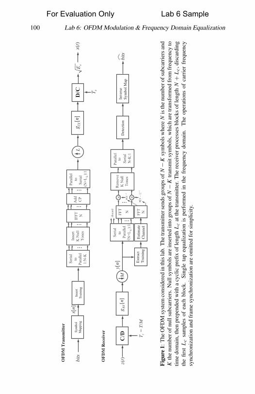
In this lab you will implement the key features of the orthogonal frequencydivision multiplexing (OFDM) multicarrier modulation technique. OFDM isa transmission technique with a special structure that permits low complex-ity linear equalization at the receiver. Several commercial wireless systemshave adopted OFDM modulation including wireless LAN standards like IEEE802.11g, IEEE 802.11a, and IEEE 802.11n; broadband wireless access in-cluding IEEE 802.16 (WiFi); mobile broadband wireless known as IEEE802.20; digital video broadcasting DVB (used in Europe); as well as severalreleases of the 3GPP cellular standards. The OFDM system considered inthis lab is illustrated in Figure 1.
Although the design of an OFDM system has several important differ-ences from the single carrier system considered in previous labs, it must stillperform many of the same functions (e.g., channel estimation, equalization,and frequency offset estimation). In this lab you will still perform all func-tions related to synchronization and channel estimation in the time domainusing the same training sequence discussed in Lab 5. The framing structureconsidered in this lab is illustrated in Figure 2.
For the pre-lab submission, you have to turn in the three VIs described inSection 2 (OFDM modulate.vi, OFDM demodulate.vi, and FEQ.vi). Further,you have to submit the answers to questions in Section 2.
1 Background
1.1 OFDM Modulation
Figure 1 shows a block diagram of the basic OFDM modulator you will beimplementing in this lab. OFDM is a type of digital modulation where infor-mation is modulated into discrete-time sinusoids. With OFDM, the symbolsafter the constellation mapping are considered to start in the frequency do-main. OFDM operates on groups of symbols, the resulting group of symbolsbeing called an OFDM symbol. To begin the explanation, we assume K = 0and that there are N frequency-domain symbols in one OFDM symbol. Thenumber of subcarriers is given by N , typically a power of 2. The transmitteroperates as follows. Given {s[n]}N−1
n=0 and cyclic prefix of length Lc, the
99
For Evaluation Only Lab 6 Sample
�
�
“book” — 2011/9/29 — 15:18 — page 100 — #112�
�
�
�
�
�
100 Lab 6: OFDM Modulation & Frequency Domain Equalization
OF
DM
Tra
nsm
itte
r
[]
sn
D/C
xE
()
xt
xT
L[
]TXg
nSy
mbo
lM
appi
ngbi
ts
OF
DM
Rec
eive
r
()
zt
[]
RXgn
C/D zT
= T
/M
[]
yn
MD
etec
tion
Inve
rse
Sym
bol M
apbi
tsM
Inse
rtTr
aini
ng
Ext
ract
Tra
inin
g
Seria
lto
Para
llel
1:N
-K
IFFT N
Para
llel
toSe
rial
(N+L
):1
Add CP
c
...
...
...
Ser
ial
toPa
ralle
lN
+L
):1 c(
FFT N
...
...
disc
ard
Est
imat
eC
hann
el F
FT
N
Para
llel
to S
eria
l N
-K:1
Rem
ove
K N
ull
Tone
s
Inse
rtK
Nul
lTo
nes
...
Fig
ure
1:T
heO
FDM
syst
emco
nsid
ered
inth
isla
b.T
hetr
ansm
itter
send
sgr
oups
ofN−K
sym
bols
whe
reN
isth
enu
mbe
rofs
ubca
rrie
rsan
dK
the
num
bero
fnul
lsub
carr
iers
.N
ulls
ymbo
lsar
ein
sert
edin
togr
oups
ofN−K
tran
smit
sym
bols
,whi
char
etr
ansf
orm
edfr
omfr
eque
ncy
totim
edo
mai
n,th
enpr
epen
ded
with
acy
clic
prefi
xof
leng
thL
cat
the
tran
smitt
er.
The
rece
iver
proc
esse
sbl
ocks
ofle
ngth
N+
Lc,d
isca
rdin
gth
efir
stL
csa
mpl
esof
each
bloc
k.Si
ngle
tap
equa
lizat
ion
ispe
rfor
med
inth
efr
eque
ncy
dom
ain.
The
oper
atio
nsof
carr
ier
freq
uenc
ysy
nchr
oniz
atio
nan
dfr
ame
sync
hron
izat
ion
are
omitt
edfo
rsi
mpl
icity
.
For Evaluation Only Lab 6 Sample

�
�
“book” — 2011/9/29 — 15:18 — page 101 — #113�
�
�
�
�
�
Lab 6: OFDM Modulation & Frequency Domain Equalization 101
...preamble
CP OFDM CP OFDM1 1 2 2
OFDM symbol
OFDM payload
train train
Figure 2: The framing structure considered in this lab. The preamble consists of tworepeated training sequences from Lab 5 (a total of four Barker codes). The preambleis sent using the usual complex pulse amplitude modulation. Subsequent data is sentusing OFDM modulation, which is a block-based modulation technique.
transmitter produces the sequence
w[n] = 1
N
N−1∑n=0
s[m]ej2πm(n−Lc)
N n = 0, ..., N + Lc − 1
that is passed to the transmit pulseshaping filter. The samples from n =Lc, Lc + 1, . . . , N + Lc − 1 are the output of the inverse discrete Fouriertransform (DFT) of the input symbols {s[m]}N−1
n=0 , which could be imple-mented using the fast Fourier transform (FFT).
Now observe thatw[n] = w[n+N ]
for n = 0, 1, . . . , Lc − 1. This means that the first Lc samples of w[n] arethe same as the last Lc samples. The first Lc samples are known as a cyclicprefix. The length of the cyclic prefix Lc should be at least as long as Lh.This will ensure that there is no intersymbol interference between adjacentOFDM symbols (i.e., the CP “guards” against ISI). The cyclic prefix servesanother important purpose. It helps convert (part of) the linear convolutioninto a circular convolution.
In OFDM rectangular pulse-shaping is common; windowing of the sym-bols is used to shape the frequency spectrum. This is not considered in thislab.
Assuming carrier frequency synchronization and frame synchronizationhave been accomplished, the received observes the following signal aftermatched filtering, symbol timing, frame synchronization, and downsampling
y[n] =L∑
�=0
h[�]w[n− �] + v[n].
The receiver operates on blocks of data.
For Evaluation Only Lab 6 Sample

�
�
“book” — 2011/9/29 — 15:18 — page 102 — #114�
�
�
�
�
�
102 Lab 6: OFDM Modulation & Frequency Domain Equalization
Note: This exposition implies that to recover multiple blocks of symbols(i.e., the input to the OFDM modulator), you will need to process multipleOFDM symbols, each of length N + Lc. Assuming that the indexing startsat the first OFDM symbol, the receiver discards the first Lc samples to formfor n = 0, 1, . . . , N − 1 (neglecting noise) y[n] = y[n + Lc]. With somemathematical manipulations it can be shown that
y[n] =L∑
l=0
h[l]w[n+ Lc − l]n = 0, ..., N − 1
= 1
N
L∑l=0
h[l]N−1∑m=0
s[m]ej2πm(n+Lc−Lc−l)
N
= 1
N
L∑l=0
h[l]N−1∑m=0
s[m]ej2π mnN e−j2π ml
N
= 1
N
N−1∑m=0
(L∑
l=0
h[l]e−j2π mlN
)s[m]ej2π mn
N .
The receiver then takes the DFT (or FFT) of these samples to produce(after some simplification)
Y [k] = DFT [y[n]]= H [k]s[k] + V [k], (1)
where
H [k] =L∑
l=0
h[l]e−j2π klN ,
which is just the DFT of the zero padded channel. The frequency domain in-terpretation of OFDM comes from Eq. (1). Essentially information is sent ondiscrete-time sinusoids, or carriers. The information on the kth discrete-timesinusoid experiences the channel response determined by H [k]. Equaliza-tion simply requires dividing Y [k] by H [k]. We refer to this as the frequencydomain equalizer (FEQ).
The following parameters are useful when discussing OFDM.
• T is sample period.
• T (N + Lc) is the OFDM symbol period.
• The guard interval, or cyclic prefix duration, is LcT .
For Evaluation Only Lab 6 Sample

�
�
“book” — 2011/9/29 — 15:18 — page 103 — #115�
�
�
�
�
�
Lab 6: OFDM Modulation & Frequency Domain Equalization 103
• The passband bandwidth is 1/T assuming use of a sinc pulseshapingfilter.
• The subcarrier spacing �c = BWN= 1
NT.
The length of the cyclic prefix Lc should be the same as or exceed theorder of the channel response Lh. Recall that the length of a channel oforder Lh is Lh+ 1. This will ensure that there is no intersymbol interferencebetween adjacent OFDM symbols (i.e., the CP “guards” against ISI). Theguard interval is a form of overhead. This reduces the effective data rate thatis transmitted (i.e., for an OFDM system with OFDM sample rate Rs and M
bits/symbol, the effective data rate Rd < Rs).The guard interval serves to separate different OFDM symbols thus the
name. In practice the guard interval is determined by the maximum delayspread. As the bandwidth increases, Lc must increase to compensate. Thesubcarrier spacing refers to the spacing between adjacent subcarriers as mea-sured on a spectrum analyzer. The larger the N , the smaller the subcarrierspacing. The subcarrier spacing determines the sensitivity to Doppler andresidual carrier frequency offset.
The subcarrier spacing is inversely proportional to the number of subcarri-ers N . This means that as N increases you will get higher spectral efficiency,but at the cost of increased sensitivity to frequency offsets.
It is common for not all subcarriers to be used in an OFDM system. Somesubcarriers are usually “nulled” or “zeroed out” in the frequency domain(i.e., the null tones). The zero frequency or DC is commonly nulled due toRF distortion at DC. Also, guard bands (i.e., frequencies at the edges of thefrequency response corresponding to those around s[N/2]) are commonlynulled to prevent interference with signals in adjacent frequency bands. Inthe lab we assume that K subcarriers are zeroed with the zero locations beingspecified separately.
2 Pre-Lab
In this lab you will implement the OFDM modulator and demodulator asdescribed in the background section. You are required to build two VIs:OFDM modulate.vi and OFDM demodulate.vi. These VIs will implementthe appropriate transmit and receive operations from Figure 1.
Before discussing the details of these VIs, you will learn about a set ofhelper VIs which have been provided to you in OFDM comm1.0.llb, a newdigital communications library for processing related to OFDM. The VIsdescribed in Table 1 are located in OFDM comm1.0.llb and may be helpfulin your implementations of OFDM modulation and demodulation.
For Evaluation Only Lab 6 Sample
�
�
“book” — 2011/9/29 — 15:18 — page 104 — #116�
�
�
�
�
�
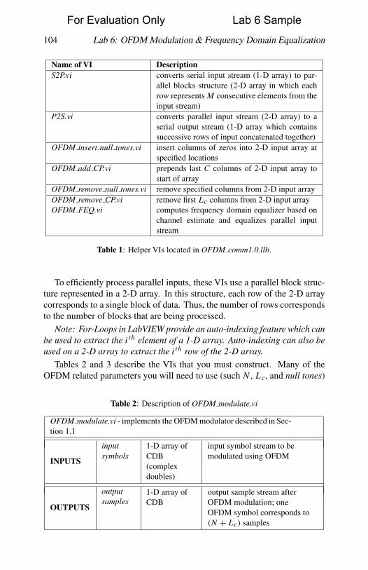
104 Lab 6: OFDM Modulation & Frequency Domain Equalization
Name of VI DescriptionS2P.vi converts serial input stream (1-D array) to par-
allel blocks structure (2-D array in which eachrow represents M consecutive elements from theinput stream)
P2S.vi converts parallel input stream (2-D array) to aserial output stream (1-D array which containssuccessive rows of input concatenated together)
OFDM insert null tones.vi insert columns of zeros into 2-D input array atspecified locations
OFDM add CP.vi prepends last C columns of 2-D input array tostart of array
OFDM remove null tones.vi remove specified columns from 2-D input arrayOFDM remove CP.vi remove first Lc columns from 2-D input arrayOFDM FEQ.vi computes frequency domain equalizer based on
channel estimate and equalizes parallel inputstream
Table 1: Helper VIs located in OFDM comm1.0.llb.
To efficiently process parallel inputs, these VIs use a parallel block struc-ture represented in a 2-D array. In this structure, each row of the 2-D arraycorresponds to a single block of data. Thus, the number of rows correspondsto the number of blocks that are being processed.
Note: For-Loops in LabVIEW provide an auto-indexing feature which canbe used to extract the ith element of a 1-D array. Auto-indexing can also beused on a 2-D array to extract the ith row of the 2-D array.
Tables 2 and 3 describe the VIs that you must construct. Many of theOFDM related parameters you will need to use (such N , Lc, and null tones)
Table 2: Description of OFDM modulate.vi
OFDM modulate.vi - implements the OFDM modulator described in Sec-tion 1.1
INPUTS
inputsymbols
1-D array ofCDB(complexdoubles)
input symbol stream to bemodulated using OFDM
OUTPUTS
outputsamples
1-D array ofCDB
output sample stream afterOFDM modulation; oneOFDM symbol corresponds to(N + Lc) samples
For Evaluation Only Lab 6 Sample
�
�
“book” — 2011/9/29 — 15:18 — page 105 — #117�
�
�
�
�
�
Lab 6: OFDM Modulation & Frequency Domain Equalization 105
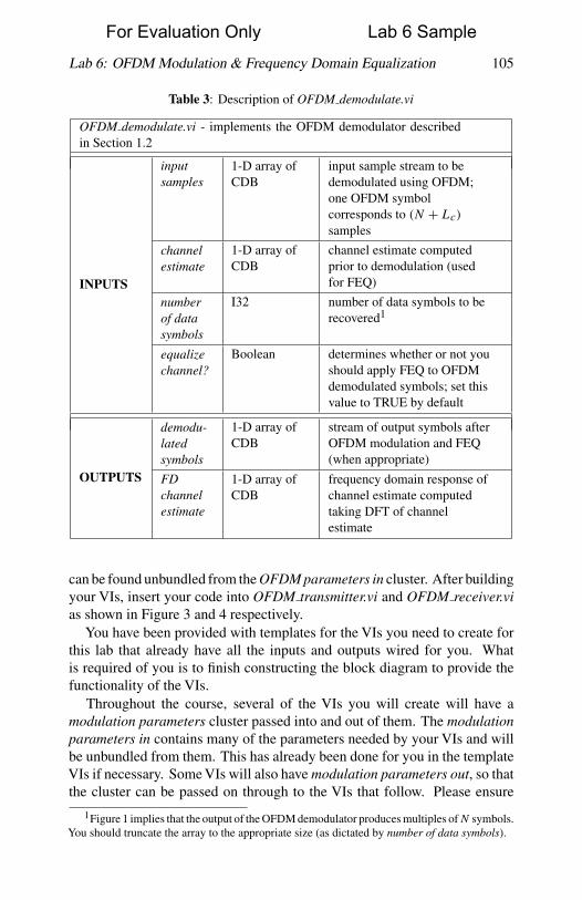
Table 3: Description of OFDM demodulate.vi
OFDM demodulate.vi - implements the OFDM demodulator describedin Section 1.2
INPUTS
inputsamples
1-D array ofCDB
input sample stream to bedemodulated using OFDM;one OFDM symbolcorresponds to (N + Lc)
samples
channelestimate
1-D array ofCDB
channel estimate computedprior to demodulation (usedfor FEQ)
numberof datasymbols
I32 number of data symbols to berecovered1
equalizechannel?
Boolean determines whether or not youshould apply FEQ to OFDMdemodulated symbols; set thisvalue to TRUE by default
OUTPUTS
demodu-latedsymbols
1-D array ofCDB
stream of output symbols afterOFDM modulation and FEQ(when appropriate)
FDchannelestimate
1-D array ofCDB
frequency domain response ofchannel estimate computedtaking DFT of channelestimate
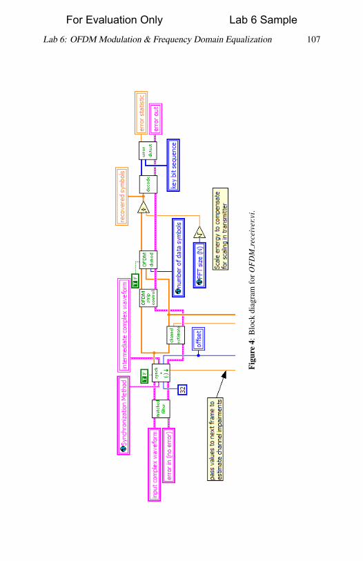
can be found unbundled from the OFDM parameters in cluster. After buildingyour VIs, insert your code into OFDM transmitter.vi and OFDM receiver.vias shown in Figure 3 and 4 respectively.
You have been provided with templates for the VIs you need to create forthis lab that already have all the inputs and outputs wired for you. Whatis required of you is to finish constructing the block diagram to provide thefunctionality of the VIs.
Throughout the course, several of the VIs you will create will have amodulation parameters cluster passed into and out of them. The modulationparameters in contains many of the parameters needed by your VIs and willbe unbundled from them. This has already been done for you in the templateVIs if necessary. Some VIs will also have modulation parameters out, so thatthe cluster can be passed on through to the VIs that follow. Please ensure
1Figure 1 implies that the output of the OFDM demodulator produces multiples of N symbols.You should truncate the array to the appropriate size (as dictated by number of data symbols).
For Evaluation Only Lab 6 Sample

�
�
“book” — 2011/9/29 — 15:18 — page 106 — #118�
�
�
�
�
�
106 Lab 6: OFDM Modulation & Frequency Domain Equalization
Fig
ure
3:B
lock
diag
ram
for
OF
DM
tran
smit
ter.v
i.
For Evaluation Only Lab 6 Sample
�
�
“book” — 2011/9/29 — 15:18 — page 107 — #119�
�
�
�
�
�
Lab 6: OFDM Modulation & Frequency Domain Equalization 107
Fig
ure
4:B
lock
diag
ram
for
OF
DM
rece
iver
.vi.
For Evaluation Only Lab 6 Sample

�
�
“book” — 2011/9/29 — 15:18 — page 108 — #120�
�
�
�
�
�
108 Lab 6: OFDM Modulation & Frequency Domain Equalization
that these clusters remain wired the way they are in the template VIs, aschanging how they are wired will cause VIs further down the line to break.In addition, you will now have access to the OFDM parameters cluster forOFDM-specific parameters you will need for you VIs. These are accessed inthe same way that parameters from the modulation parameters cluster are.
After inserting your code into the simulator provided to you, verify thatyour code is working properly by observing that the transmitted and receivedconstellations reflect the appropriate PSK modulation scheme you have cho-sen.
Pre-Lab Turn In
1. Submit your implementation of OFDM modulate.vi and OFDM de-modulate.vi. Remember, you will be penalized if you do not wire errorcluster inputs and outputs. Note: If you need to generate additionalsubVIs for this or any future labs, please submit these subVIs alongwith your other pre-lab VIs.
2. EXTRA CREDIT (20pts) - implement FEQ.vi (i.e., your own versionof OFDM FEQ.vi). Table 4 describes the details of this VI. Submityour implementation of FEQ.vi with your other VIs. Remember towire error clusters.
Table 4: Description of FEQ.vi
FEQ.vi - performs frequency domain equalization as described in Section 1.3
INPUTS
input 2-D array ofCDB
parallel block structure ofsymbols (i.e., output of DFT);each row corresponds to ablock of N symbols (i.e.,{Y [k]}N−1
k=0 )
channelestimate
1-D array ofCDB
channel estimate computedprior to demodulation
OUTPUTS
equalizedoutput
2-D array ofCDB
equalized symbols; each rowcorresponds to a block of N
symbols (i.e., {X[k]}N−1k=0
where X[k] = Y [k]/H [k])FDchannelestimate
1-D array ofCDB
frequency domain response ofchannel estimate computed bytaking DFT of channelestimate (i.e.,H [k] = DFT {h[l]})
For Evaluation Only Lab 6 Sample
�
�
“book” — 2011/9/29 — 15:18 — page 109 — #121�
�
�
�
�
�
Lab 6: OFDM Modulation & Frequency Domain Equalization 109
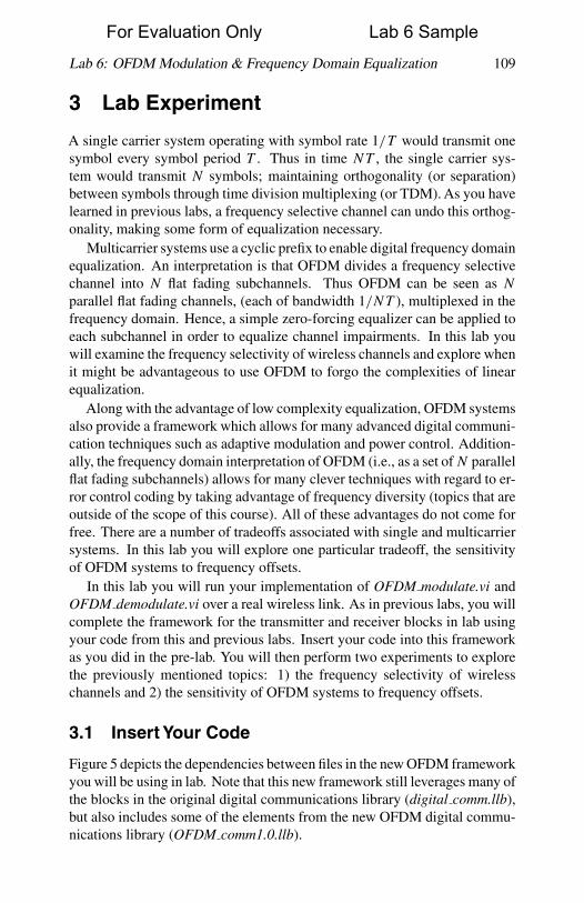
3 Lab Experiment
A single carrier system operating with symbol rate 1/T would transmit onesymbol every symbol period T . Thus in time NT , the single carrier sys-tem would transmit N symbols; maintaining orthogonality (or separation)between symbols through time division multiplexing (or TDM). As you havelearned in previous labs, a frequency selective channel can undo this orthog-onality, making some form of equalization necessary.
Multicarrier systems use a cyclic prefix to enable digital frequency domainequalization. An interpretation is that OFDM divides a frequency selectivechannel into N flat fading subchannels. Thus OFDM can be seen as N
parallel flat fading channels, (each of bandwidth 1/NT ), multiplexed in thefrequency domain. Hence, a simple zero-forcing equalizer can be applied toeach subchannel in order to equalize channel impairments. In this lab youwill examine the frequency selectivity of wireless channels and explore whenit might be advantageous to use OFDM to forgo the complexities of linearequalization.
Along with the advantage of low complexity equalization, OFDM systemsalso provide a framework which allows for many advanced digital communi-cation techniques such as adaptive modulation and power control. Addition-ally, the frequency domain interpretation of OFDM (i.e., as a set of N parallelflat fading subchannels) allows for many clever techniques with regard to er-ror control coding by taking advantage of frequency diversity (topics that areoutside of the scope of this course). All of these advantages do not come forfree. There are a number of tradeoffs associated with single and multicarriersystems. In this lab you will explore one particular tradeoff, the sensitivityof OFDM systems to frequency offsets.
In this lab you will run your implementation of OFDM modulate.vi andOFDM demodulate.vi over a real wireless link. As in previous labs, you willcomplete the framework for the transmitter and receiver blocks in lab usingyour code from this and previous labs. Insert your code into this frameworkas you did in the pre-lab. You will then perform two experiments to explorethe previously mentioned topics: 1) the frequency selectivity of wirelesschannels and 2) the sensitivity of OFDM systems to frequency offsets.
3.1 Insert Your Code
Figure 5 depicts the dependencies between files in the new OFDM frameworkyou will be using in lab. Note that this new framework still leverages many ofthe blocks in the original digital communications library (digital comm.llb),but also includes some of the elements from the new OFDM digital commu-nications library (OFDM comm1.0.llb).
For Evaluation Only Lab 6 Sample

�
�
“book” — 2011/9/29 — 15:18 — page 110 — #122�
�
�
�
�
�
110 Lab 6: OFDM Modulation & Frequency Domain Equalization
Figure 5: Hierarchy of files for OFDM framework.
Once you have inserted your code for OFDM modulate.vi and OFDM de-modulate.vi into OFDM transmitter.vi and OFDM receiver.vi respectively,you will need to set up the parameters listed below. These parameters arelocated on the front panels of top tx.vi and top rx.vi. Leave any unspecifiedparameters set to their default value.
• Packet length = 500 bits
• Modulation type = QPSK
• Channel estimate length = 4
• FFT size (N ) = 64
• Length of CP (Lc) = 8
• Null tones = {0, 31, 32, 33}
3.2 Frequency Selectivity of Wireless Channels
In this first experiment you will observe the frequency response of narrowbandand wideband channels. Set up the following parameters for a narrowbandsystem.
• TX sample rate = 4 MSamp/sec
For Evaluation Only Lab 6 Sample

�
�
“book” — 2011/9/29 — 15:18 — page 111 — #123�
�
�
�
�
�
Lab 6: OFDM Modulation & Frequency Domain Equalization 111
• TX oversample factor = 20
• RX sample rate = 4 MSamp/sec
• RX oversample factor = 20
• Capture time = 2.4 msec
After transmitting a packet successfully, observe the frequency responseof the narrowband channel, using the Channel Response graph located onthe front panel of OFDM receiver.vi. Also examine the instantaneous power-delay profile using the appropriate graph on the front panel of the same VI.Take note of the effective length of the channel response (i.e., the number ofnonzero taps in the channel).
Next, you will observe the frequency response of a wideband channel.To set up a wideband system, set the following parameters in your OFDMsystem.
• TX sample rate = 20 MSamp/sec
• TX oversample factor = 4
• RX sample rate = 10 MSamp/sec
• RX oversample factor = 2
• Capture time = 100 μsec
For this part of the experiment it is critical that you place your antennas at an el-evated height so that all reflected paths in the lab environment reach the anten-nas. After transmitting a packet successfully observe the frequency responseand power-delay profile of the wideband channel in OFDM receiver.vi. Also,take note of the effective length of the channel response.
Questions
Answer the following questions regarding the frequency selectivity of wire-less channels.
1. According to the parameters above, what is the respective OFDM sym-bol rate in the narrowband and wideband systems you have set up (i.e.,the reciprocal of the OFDM symbol period as previously defined)?
2. What are the effective lengths of the narrowband and wideband chan-nels respectively?
3. Describe the frequency responses of each channel. In particular, arethe frequency responses of these channels frequency selective or flat?
For Evaluation Only Lab 6 Sample
�
�
“book” — 2011/9/29 — 15:18 — page 112 — #124�
�
�
�
�
�
112 Lab 6: OFDM Modulation & Frequency Domain Equalization
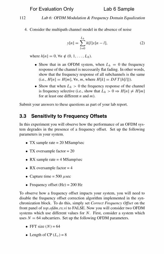
4. Consider the multipath channel model in the absence of noise
y[n] =Lh∑l=0
h[l]x[n− l], (2)
where h[n] = 0, ∀n /∈ (0, 1, . . . , Lh).
• Show that in an OFDM system, when Lh = 0 the frequencyresponse of the channel is necessarily flat fading. In other words,show that the frequency response of all subchannels is the same(i.e., H [n] = H [m], ∀n, m, where H [k] = DFT {h[l]}).• Show that when Lh > 0 the frequency response of the channel
is frequency selective (i.e., show that Lh > 0⇒ H [n] �= H [m]for at least one different n and m).
Submit your answers to these questions as part of your lab report.
3.3 Sensitivity to Frequency Offsets
In this experiment you will observe how the performance of an OFDM sys-tem degrades in the presence of a frequency offset. Set up the followingparameters in your system.
• TX sample rate = 20 MSamp/sec
• TX oversample factor = 20
• RX sample rate = 4 MSamp/sec
• RX oversample factor = 4
• Capture time = 500 μsec
• Frequency offset (Hz) = 200 Hz
To observe how a frequency offset impacts your system, you will need todisable the frequency offset correction algorithm implemented in the syn-chronization block. To do this, simply set Correct Frequency Offset on thefront panel of top ofdm rx.vi to FALSE. Now you will consider two OFDMsystems which use different values for N . First, consider a system whichuses N = 64 subcarriers. Set up the following OFDM parameters.
• FFT size (N ) = 64
• Length of CP (Lc) = 8
For Evaluation Only Lab 6 Sample

�
�
“book” — 2011/9/29 — 15:18 — page 113 — #125�
�
�
�
�
�
Lab 6: OFDM Modulation & Frequency Domain Equalization 113
• Null tones = {0, 31, 32, 33}Observe how a frequency offset impacts the received signal constellation.Also make note of the impact of a frequency offset on BER performance.Increase the amount of frequency offset in your system in increments of 200Hz and observe how the signal constellation and BER performance vary. Nowconsider a system which uses N = 1024 subcarriers.
• FFT size (N ) = 1024
• Length of CP (Lc) = 32
• Null tones = {0, 511, 512, 513}Again, observe how a frequency offset of just 200 Hz impacts the receivedconstellation and BER performance of your system. To understand howa frequency offset impacts OFDM systems, it is convenient to think of afrequency offset as a shift in the frequency domain. This shifting can causewhat is known as inter-carrier interference (or ICI).
Questions
Answer the following questions about the sensitivity of OFDM systems tofrequency offsets.
1. Recall from the Lab 5 that in a single carrier system, a frequencyoffset causes a time varying phase offset which effectively “smears” thereceived constellation as it rotates it. How is the impact of a frequencyoffset in OFDM systems different from that of single carrier systems?In particular, how is the impact on the signal constellation different?
2. What is the subcarrier spacing �c of your system when N = 1024 and64 respectively?
3. Which of the systems (i.e., N = 1024 or 64) is more severely impactedby a 200 Hz frequency offset? Why?
4. As mentioned, frequency offsets can be interpreted as shifts in thefrequency domain. There is a duality between the effect of this shiftingin a multicarrier system and symbol timing error in a single carriersystem (discussed in Part 2 of Lab 2).
Discuss this relationship between the effect of symbol timing errorin single carrier systems and frequency offset in OFDM systems. Besure to include in your discussion the effect of each impairment on thereceived signal constellation. Hint: Think about the impact of eachtype of error on the orthogonality (or separation) between symbols.
Submit your answers to these questions as part of your lab report.
For Evaluation Only Lab 6 Sample
�
�
“book” — 2011/9/29 — 15:18 — page 114 — #126�
�
�
�
�
�
114 Lab 6: OFDM Modulation & Frequency Domain Equalization
3.4 Lab Turn In
Show the instructor that you have replaced the OFDM modulator and de-modulator in lab with your own code. Demonstrate to the instructor that yourcode is working properly. Also show the instructor that your OFDM system“breaks” down when you have frequency offsets greater than the subcarrierspacing that are not corrected for (i.e., when foffset > �c). Answer all of thequestions above and submit your answers in your lab report.
DIRECTIONS FOR LAB SUBMISSION
Your lab report should include the following.
1. Answer all questions from the lab experiment (i.e., do not reanswerpre-lab questions).
2. Discuss any problems you might have encountered and how you over-came these obstacles.
3. In this lab you observed how an OFDM system operates over a realwireless link. Answer the following questions about your experiencein lab.
(a) OFDM systems have an inherent overhead due to the need for acyclic prefix. Assuming QPSK modulation, in terms of N , Lc,T , and the number of null tones K (all as previously defined),what is the effective data rate of the OFDM system in lab?
(b) Based on your experience in lab, discuss why or why not youmight use an OFDM system in a wideband and narrowband sys-tem respectively. Include in your discussion some of the bene-fits/costs of each scenario.
(c) OFDM systems in general have a large degree of flexibility. Nameat least three parameters of OFDM systems which contribute tothis flexibility and comment on how they do so.
For Evaluation Only Lab 6 Sample