Lab 3: UMTS (Universal Mobile Telecommunication …bgenoves/P_UMTS/Practica3English.pdf · 1...
5
Mobile Communications (Lab) Department of Signal Theory and Communications February - May 2017 Lab 3: UMTS (Universal Mobile Telecommunication System) signal generation on FRAMED-SOFT based on the Software Defined Radio environment NI LabVIEW environment and NI USRP-2920 hardware (4 hours) Objectives The objectives of the lab can be summarized as follows: • Reinforce the knowledge about control signals in UMTS. • Reinforce the knowledge about the UMTS system. • Acquire skills handling the communications lab equipment such as transceivers with which being able to work by means of the Software Defined Radio (SDR), as well as to get familiar with the NI LabVIEW c environment. When this lab is finished, the student will have to have understood in a precise manner how the UMTS control channels work, such as the SCH (Synchronization CHannel) and the CPICH (Common PIlot CHannel), from the generation of the signal to the transmission of it. 1 FRAMED-SOFT The Flexible Radio Access Mobile Environment Defined by SOFTware (FRAMED-SOFT) is a platform designed in The University Carlos III of Madrid with the aim of getting closer to the students the mobile communication standards. The platform is divided into three parts, namely, the hardware, the base stations and the receivers. The hardware part is composed of the NI USRPs, usually two of them for each software part. Although the same USRP could work simultaneously as transmitter and receiver (one antenna for transmission and the other one for reception), this design uses two different USRP connected by the provided interconnection wire. This way, the design of each part is simpler, it allows the use of less powerful computers for controlling the USRP. FRAMED-SOFT allows the modification or optimization of the transmission/reception parts independently, what is very useful for practical work. Thus, a base station needs two USRPs, one for transmission and the other one for reception. Since both are controlled by different LabVIEW designs (even running in different computers although this is not mandatory), they interchange information by using the interconnection wire provided with the USRP bundle. 0 r Alejandro Lancho Serrano
Transcript of Lab 3: UMTS (Universal Mobile Telecommunication …bgenoves/P_UMTS/Practica3English.pdf · 1...

Mobile Communications (Lab)Department of Signal Theory and Communications
February - May 2017
Lab 3: UMTS (Universal Mobile Telecommunication System)signal generation on FRAMED-SOFT based on the Software
Defined Radio environment NI LabVIEW environment and NIUSRP-2920 hardware
(4 hours)
ObjectivesThe objectives of the lab can be summarized as follows:
• Reinforce the knowledge about control signals in UMTS.
• Reinforce the knowledge about the UMTS system.
• Acquire skills handling the communications lab equipment such as transceivers with whichbeing able to work by means of the Software Defined Radio (SDR), as well as to get familiarwith the NI LabVIEW c© environment.
When this lab is finished, the student will have to have understood in a precise manner howthe UMTS control channels work, such as the SCH (Synchronization CHannel) and the CPICH(Common PIlot CHannel), from the generation of the signal to the transmission of it.
1 FRAMED-SOFT
The Flexible Radio Access Mobile Environment Defined by SOFTware (FRAMED-SOFT) isa platform designed in The University Carlos III of Madrid with the aim of getting closer tothe students the mobile communication standards. The platform is divided into three parts,namely, the hardware, the base stations and the receivers. The hardware part is composed ofthe NI USRPs, usually two of them for each software part. Although the same USRP couldwork simultaneously as transmitter and receiver (one antenna for transmission and the other onefor reception), this design uses two different USRP connected by the provided interconnectionwire. This way, the design of each part is simpler, it allows the use of less powerful computersfor controlling the USRP.
FRAMED-SOFT allows the modification or optimization of the transmission/reception partsindependently, what is very useful for practical work. Thus, a base station needs two USRPs,one for transmission and the other one for reception. Since both are controlled by differentLabVIEW designs (even running in different computers although this is not mandatory), theyinterchange information by using the interconnection wire provided with the USRP bundle.
0r Alejandro Lancho Serrano

The base station part allows one to select the GSM or the UMTS standard. Dependingon which one is chosen, the adequate LabVIEW design is executed. Since both standardsare completely different from the physical layer point of view, two different designs have beenimplemented. However, from the logical point of view, both of them have several similarities.
It should be noted here that within the LabVIEW interface, there is the NI LabVIEWMathScript RT that allows the use of Matlab code directly into the LabVIEW designs. Thiscan be used when a complex algorithm needs to be evaluated first in order to decide if it will beimplemented or not.
In this lab work, the student will receive a incomplete version of FRAMED-SOFT andhe/she, after studying the corresponding standard, must program the parts that are required.This way, the student becomes aware of the functioning of mobile communication technologies.
In further lab sessions, the student will be asked for an open ended-design experience thatconsists in developing important parts of a communication system: the channel estimation,equalization, rake receiver, synchronization, etc.
2 Lab description
The goal of this lab consist in generating, using LabVIEW, the transmission of two of thechannels of UMTS, more concretely the synchronization channel SCH and the primary pilotchannel used for the channel estimation (P-CPICH), assuming NO diversity.
Once the transmission sequence is obtained, it will be send by the NI-USRP transmitterhardware of National Instruments towards a USRP receiver where the signal will be able to beanalyzed in time and frequency. This will be carried out using the FRAMED-SOFT platform.For further information, see Fig. 1.
Figure 1: Lab process diagram
For the correct execution of the lab, it is highly recommended to have read theLabVIEW tutorials (web link).
3 SCH generation (Synchronization CHannel)
As the student should remember from the Mobile Communications theory lessons, the UMTSsignal uses the spreading spectrum technique for various things, such as interference protection,
multipath protection and it is also used for the multiple access channel (known as CDMA -Code Division Multiple Access). Apart from using codes to differentiate users, it also uses codesto multiplex channels. One of the most important channels in UMTS is the Synchronizationchannel, SCH. This channel, is unique for each cell and it is generated by two sub-channels:primary and secondary [1]. The student is asked for generating this SCH channel according to[1] and [2] for a 10 ms frame, when there is NO diversity in transmission.
To build the secondary code, use the Scrambling group code number 0.
4 P-CPICH generation (Primary Common PIlot CHannel)
The CPICH channel has always a fixed rate of 30 kbps with a spreading factor of 256, and isthe phase reference for the SCH channel. It is a fixed sequence (although variable in function ofcertain parameters, such us the diversity) and known both in transmission and reception [1] and[2]. The student is asked for generating the primary CPICH. Recall that there is no diversity.
5 Generation of the complete signal. Base Band and RF
Once both channel have been generated, multiplex them to generate a joint base band signal,and represent the constellation to be sent. To know if the channels that have been implementedare correct, some .VI will be provided to check the SCH, CPICH and the joint multiplexed SCHand CPICH frame.
Now the RF signal has to be obtained. To do so, use a carrier frequency of 600 MHz. Togenerate the RF signal, one only has to indicate to the transmitter module of the FRAMED-SOFT platform the carrier frequency to use and introduce the base band signal. The USRP willgenerate the RF signal and it will send it.
In the receiver module the spectrum and the time signal must be observed, checking if it fitswith the studied in the theory classes.
Although in a real UMTS signal would be necessary ti generate also the P-PCCPCH (PrimaryCommon Control Physical CHannel), to avoid a larger complexity, it is not necessary to generateit in this lab.
6 Use of the NI-USRP. Transmitter and Receiver modules
To observe the time signal and the sepctrum, two .VIs are provided. One that carries out thetransmission, and the other the reception.
The only thing that has to be done by the student in the transmitter .VI is to connect tothe variable Trama Final, the frame that has been generated by multiplexing the SCH andCPICH. To visualize it, see Fig. 2. Besides, check that the parameters in the Front Panel areset as shown in Fig. 3.
With respect to the receiver, it is only necessary to check if the parameters are set as in Fig.4, and execute the .VI to receive the signal.
7 Use of the .VI Check Sequences
The use of this .VI is extremely simple. The student will have to introduce the generated frames(SCH, CPICH or SCH+CPICH) and decide the option to be checked using the control booleanvariables. In case of activating both SCH and CPICH, the multiplexed frame will be checked,and also the SCH and CPICH individually.
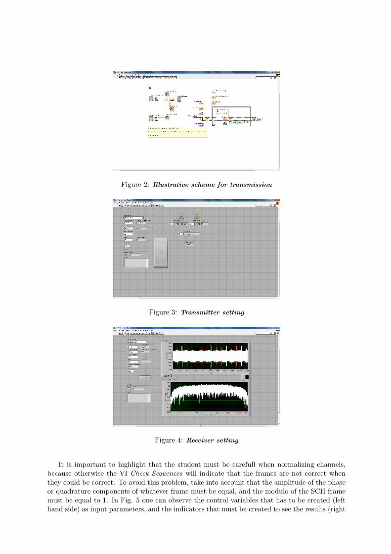
Figure 2: Illustrative scheme for transmission
Figure 3: Transmitter setting
Figure 4: Receiver setting
It is important to highlight that the student must be carefull when normalizing channels,because otherwise the VI Check Sequences will indicate that the frames are not correct whenthey could be correct. To avoid this problem, take into account that the amplitude of the phaseor quadrature components of whatever frame must be equal, and the modulo of the SCH framemust be equal to 1. In Fig. 5 one can observe the control variables that has to be created (lefthand side) as input parameters, and the indicators that must be created to see the results (right
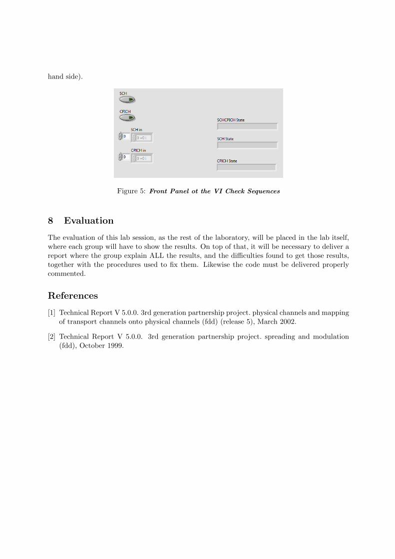
hand side).
Figure 5: Front Panel ot the VI Check Sequences
8 Evaluation
The evaluation of this lab session, as the rest of the laboratory, will be placed in the lab itself,where each group will have to show the results. On top of that, it will be necessary to deliver areport where the group explain ALL the results, and the difficulties found to get those results,together with the procedures used to fix them. Likewise the code must be delivered properlycommented.
References
[1] Technical Report V 5.0.0. 3rd generation partnership project. physical channels and mappingof transport channels onto physical channels (fdd) (release 5), March 2002.
[2] Technical Report V 5.0.0. 3rd generation partnership project. spreading and modulation(fdd), October 1999.