Lab 20: Hierarchical Token Bucket
22
NETWORK TOOLS AND PROTOCOLS Lab 20: Classifying TCP traffic using Hierarchical Token Bucket (HTB) Document Version: 11-28-2019 Award 1829698 “CyberTraining CIP: Cyberinfrastructure Expertise on High-throughput Networks for Big Science Data Transfers”
Transcript of Lab 20: Hierarchical Token Bucket

NETWORK TOOLS AND PROTOCOLS
Lab 20: Classifying TCP traffic using Hierarchical Token Bucket (HTB)
Document Version: 11-28-2019
Award 1829698 “CyberTraining CIP: Cyberinfrastructure Expertise on High-throughput
Networks for Big Science Data Transfers”

Lab 20: Hierarchical Token Bucket
Page 2
Contents Overview ............................................................................................................................. 3
Objectives............................................................................................................................ 3
Lab settings ......................................................................................................................... 3
Lab roadmap ....................................................................................................................... 3
1 Introduction ................................................................................................................ 3
2 Lab topology................................................................................................................ 6
2.1 Starting host h1, host h2, host h3 and host h4 ................................................ 7
2.2 Emulating high-latency WAN ............................................................................ 8
2.3 Testing connection ........................................................................................... 9
3 Emulating a high latency wide area network (WAN) ................................................ 10
3.1 Bandwidth-delay product (BDP) and hosts’ TCP buffer size .......................... 10
3.2 Modifying hosts’ buffer size ........................................................................... 11
3.3 Setting switch S1’s buffer size to BDP ............................................................ 14
3.4 Throughput tests of two TCP competing flows .............................................. 14
4 Setting HTB at switch s2 egress interface ................................................................. 17
4.1 Defining classes .............................................................................................. 17
4.2 Defining filters ................................................................................................ 18
4.3 Throughput tests of two TCP competing flows using HTB ............................. 19
References ........................................................................................................................ 22
Lab 20: Hierarchical Token Bucket
Page 3
Overview This lab is aimed to introduce the reader to Hierarchical Token Bucket (HTB). This queueing discipline controls the use of the outbound bandwidth on a given link by classifying different kinds of traffic into several slower links. Throughput tests are conducted to evaluate the impact of dividing a physical link according to a given policy. Objectives By the end of this lab, students should be able to:
1. Understand the concept of link-sharing. 2. Define classes to allocate a maximum bandwidth to a TCP flow. 3. Associate a class to a specific flow using filters. 4. Evaluate the effects of HTB when two TCP are using the same link.
Lab settings The information in Table 1 provides the credentials of the machine containing Mininet.
Table 1. Credentials to access Client1 machine.
Device
Account
Password
Client1 admin password
Lab roadmap This lab is organized as follows:
1. Section 1: Introduction. 2. Section 2: Lab topology. 3. Section 3: Emulating a high latency wide area network (WAN). 4. Section 4: Setting HTB at switch s2 egress interface.
1 Introduction
On a network, the management of upstream link requires the implementation of a link-sharing mechanism. Without such mechanism the default behavior of the gateways routers does not necessarily lead to a fair Internet bandwidth sharing among the endpoints. The Internet is mostly based on TCP/IP which provides few features that allow network administrators to implement traffic control rules, TCP/IP does not

Lab 20: Hierarchical Token Bucket
Page 4
know the link capacity between two hosts so that, TCP protocols compete sending packets faster, when packets start getting lost it will slow down. In summary, network resource management involves two types of services: services for real-time traffic and link-sharing services1. However, in a congested network, resource management mechanism is required at the gateway router. The main functions of the link-sharing mechanism are:
• Enable routers to control the distribution of traffic on local links according to the local demand therefore, each organization has a guaranteed bandwidth.
• Enable gateways to redistribute available bandwidth among organizations.
• Specify the bandwidth according the type of traffic.
• Accommodate the available bandwidth as new services are added.
All these requirements lead to the design of a hierarchical link-sharing structure. Figure 1 depicts the relationship between classes filters and queueing disciplines. In this structure, the traffic is classified according to a class. Classes and filters are tied together to the queuing discipline. A queuing discipline can be associated with several classes. Every class must have a queuing discipline associated it. Filters are used by the queuing discipline to assign incoming packets to one of its classes. Different types of filters can be employed, for example route classifiers and u32 filters. These filters usually classify the traffic based on the source IP, destination IP, source port, destination port, TOS byte and protocol. The universal 32bit (u32) filter allows to match arbitrary bitfields in the packet.
Figure 1. Linux kernel traffic control.
1.1 HTB algorithm
HTB controls the use of the outbound bandwidth on a given link by simulate several slower links. The user specifies how to divide the physical link into simulated links and how to decide which simulated link to use for a given packet to be sent. HTB shapes traffic based on the Token Bucket Filter (TBF) algorithm, which does not depend on interface characteristics and so does not need to know the underlying bandwidth of the outgoing interface.

Lab 20: Hierarchical Token Bucket
Page 5
Figure 2 illustrates a basic structure of HTB. The classes are configured as a tree according to relationships of traffic aggregations. Only leaf classes have queue to buffer the packets belong to the class. Children classes borrow bandwidth from their parents when their packet flow exceeds the configured rate. A child will continue to attempt to borrow bandwidth until it reaches ceil, which is the maximum bandwidth available for that class. Under each class, the user can specify other queueing disciplines namely Token Bucket Filter (TBF), Stochastic Fair Queueing (SFQ), Controlled Delay (CoDel), etc. It will depend on the service that such class is intended to provide. The default queueing discipline is First-in, First-out (FIFO).
Figure 2. Hierarchical Token Bucket Structure.
The basic htb syntax used with tc is as follows: tc qdisc [add | ...] dev [dev_id] root handle 1: htb default [DEFAULT-ID]
• tc: Linux traffic control tool.
• qdisc: A queue discipline (qdisc) is a set of rules that determine the order in which packets arriving from the IP protocol output are served. The queue discipline is applied to a packet queue to decide when to send each packet.
• [add | del | replace | change | show]: This is the operation on qdisc. For example, to add the token bucket algorithm on a specific interface, the operation will be add. To change or remove it, the operation will be change or del, respectively.
• htb: enables Hierarchical Token Bucket queuing discipline.
• default: unclassified traffic will be enqueued under this class. tc class [add | ...] dev [dev_id]
• tc: Linux traffic control tool.
• class: defines a class. Classes have a host of parameters to configure their operation.
• [add | del | replace | change | show]: This is the operation on qdisc. For example, to add the token bucket algorithm on a specific interface, the operation will be add. To change or remove it, the operation will be change or del, respectively.
• rate: specifies the maximum rate this class and all its children are guaranteed. This parameter is mandatory.

Lab 20: Hierarchical Token Bucket
Page 6
• ceil: determines the maximum rate at which a class can send, if its parent has available bandwidth. The default configuration is set to the configured rate, which implies no borrowing.
• burst: denotes the number of bytes that can be burst at ceil speed, in excess of the configured rate. It should be at least as high as the highest burst of all children.
In this lab, we will use the htb AQM algorithm to control the queue size at the egress port
of a router.
2 Lab topology
Let’s get started with creating a simple Mininet topology using MiniEdit. The topology uses 10.0.0.0/8 which is the default network assigned by Mininet.
Figure 3. Lab topology.
The above topology uses 10.0.0.0/8 which is the default network assigned by Mininet. Step 1. A shortcut to MiniEdit is located on the machine’s Desktop. Start MiniEdit by clicking on MiniEdit’s shortcut. When prompted for a password, type password.
Figure 4. MiniEdit shortcut.
Step 2. On MiniEdit’s menu bar, click on File then Open to load the lab’s topology. Locate the Lab 20.mn topology file and click on Open.

Lab 20: Hierarchical Token Bucket
Page 7
Figure 5. MiniEdit’s Open dialog.
Step 3. Before starting the measurements between end-hosts, the network must be started. Click on the Run button located at the bottom left of MiniEdit’s window to start the emulation.
Figure 6. Running the emulation.
The above topology uses 10.0.0.0/8 which is the default network assigned by Mininet. 2.1 Starting host h1, host h2, host h3 and host h4
Step 1. Hold right-click on host h1 and select Terminal. This opens the terminal of host h1 and allows the execution of commands on that host.

Lab 20: Hierarchical Token Bucket
Page 8
Figure 7. Opening a terminal on host h1.
Step 2. Apply the same steps on host h2 and host h3 and open their Terminals. Step 3. Test connectivity between the end-hosts using the ping command. On host h1, type the command ping 10.0.0.3. This command tests the connectivity between host h1 and host h3. To stop the test, press Ctrl+c. The figure below shows a successful connectivity test.
Figure 8. Connectivity test using ping command.
2.2 Emulating high-latency WAN
This section emulates a high-latency WAN. We will emulate 20ms delay on switch S1’s s1-eth2 interface. Step 1. Launch a Linux terminal by holding the Ctrl+Alt+T keys or by clicking on the Linux terminal icon.

Lab 20: Hierarchical Token Bucket
Page 9
Figure 9. Shortcut to open a Linux terminal.
The Linux terminal is a program that opens a window and permits you to interact with a command-line interface (CLI). A CLI is a program that takes commands from the keyboard and sends them to the operating system to perform. Step 2. In the terminal, type the command below. When prompted for a password, type password and hit Enter. This command introduces 20ms delay to switch S1’s s1-eth1
interface. sudo tc qdisc add dev s1-eth1 root handle 1: netem delay 20ms
Figure 10. Adding delay of 20ms to switch S1’s s1-eth1 interface.
2.3 Testing connection
To test connectivity, you can use the command ping. Step 1. On the terminal of host h1, type ping 10.0.0.3. To stop the test, press Ctrl+c. The figure below shows a successful connectivity test. Host h1 (10.0.0.1) sent four packets to host h3 (10.0.0.3), successfully receiving responses back.
Figure 11. Output of ping 10.0.0.3 command.

Lab 20: Hierarchical Token Bucket
Page 10
The result above indicates that all four packets were received successfully (0% packet loss) and that the minimum, average, maximum, and standard deviation of the Round-Trip Time (RTT) were 20.080, 25.390, 41.266, and 9.166 milliseconds, respectively. The output above verifies that delay was injected successfully, as the RTT is approximately 20ms. Step 2. On the terminal of host h2, type ping 10.0.0.3. The ping output in this test should be relatively similar to the results of the test initiated by host h1 in Step 1. To stop the test, press Ctrl+c.
Figure 12. Output of ping 10.0.0.3 command.
The result above indicates that all four packets were received successfully (0% packet loss) and that the minimum, average, maximum, and standard deviation of the Round-Trip Time (RTT) were 20.090, 25.257, 40.745, and 8.943 milliseconds, respectively. The output above verifies that delay was injected successfully, as the RTT is approximately 20ms. 3 Emulating a high latency wide area network (WAN) In this section, you are going to tune the network devices in order to emulate a Wide Area Network (WAN). First, you will set the hosts’ TCP buffers to 8 · BDP therefore, the bottleneck is not in the end-hosts. Then, you will set the bottleneck bandwidth to 1Gbps in switch S1’s s1-eth1 interface. Finally, you will conduct throughput tests between two competing TCP flows when Token Bucket Filter (TBF) is configured in switch S1 to limit the bandwidth. 3.1 Bandwidth-delay product (BDP) and hosts’ TCP buffer size
In the upcoming tests, the bandwidth is limited to 1 Gbps, and the RTT (delay or latency) is 20ms. BW = 1,000,000,000 bits/second RTT = 0.02 seconds BDP = 1,000,000,000 · 0.02 = 20,000,000 bits = 2,500,000 bytes ≈ 2.5 Mbytes

Lab 20: Hierarchical Token Bucket
Page 11
1 Mbyte = 10242 bytes BDP = 2.5 Mbytes = 2.5 · 10242 bytes = 2,621,440 bytes The default buffer size in Linux is 16 Mbytes, and only 8 Mbytes (half of the maximum buffer size) can be allocated. Since 8 Mbytes is greater than 2.5 Mbytes, then no need to tune the buffer sizes on end-hosts. However, in upcoming tests, we configure the buffer size on the switch to BDP. In addition, to ensure that the bottleneck is not the hosts’ TCP buffers, we configure the buffers to 8·BDP (20,971,520). 3.2 Modifying hosts’ buffer size
For the following calculation, the bottleneck bandwidth is considered as 1 Gbps, and the round-trip time latency as 20ms.
In order to have enough TCP buffer size, we will set the TCP sending and receiving buffer to 8 · BDP in all hosts.
BW = 1,000,000,000 bits/second RTT = 0.02 seconds BDP = 1,000,000,000 · 0.02 = 20,000,000 bits = 2,500,000 bytes ≈ 2.5 Mbytes
The send and receive TCP buffer sizes should be set to 8 · BDP to ensure the bottleneck is not in the end-hosts. For simplicity, we will use 2.5 Mbytes as the value for the BDP instead of 2,500,000 bytes.
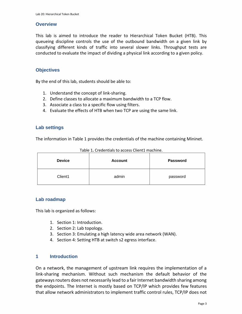
1 Mbyte = 10242 bytes BDP = 2.5 Mbytes = 2.5 · 10242 bytes = 2,621,440 bytes 8 · BDP = 8 · 2,621,440 bytes = 20,971,520 bytes Step 1. At this point, we have calculated the maximum value of the TCP sending and receiving buffer size. In order to change the receiving buffer size, on host h1’s terminal type the command shown below. The values set are: 10,240 (minimum), 87,380 (default), and 20,971,520 (maximum). sysctl -w net.ipv4.tcp_rmem=’10240 87380 20971520’
Lab 20: Hierarchical Token Bucket
Page 12
Figure 13. Receive window change in sysctl.
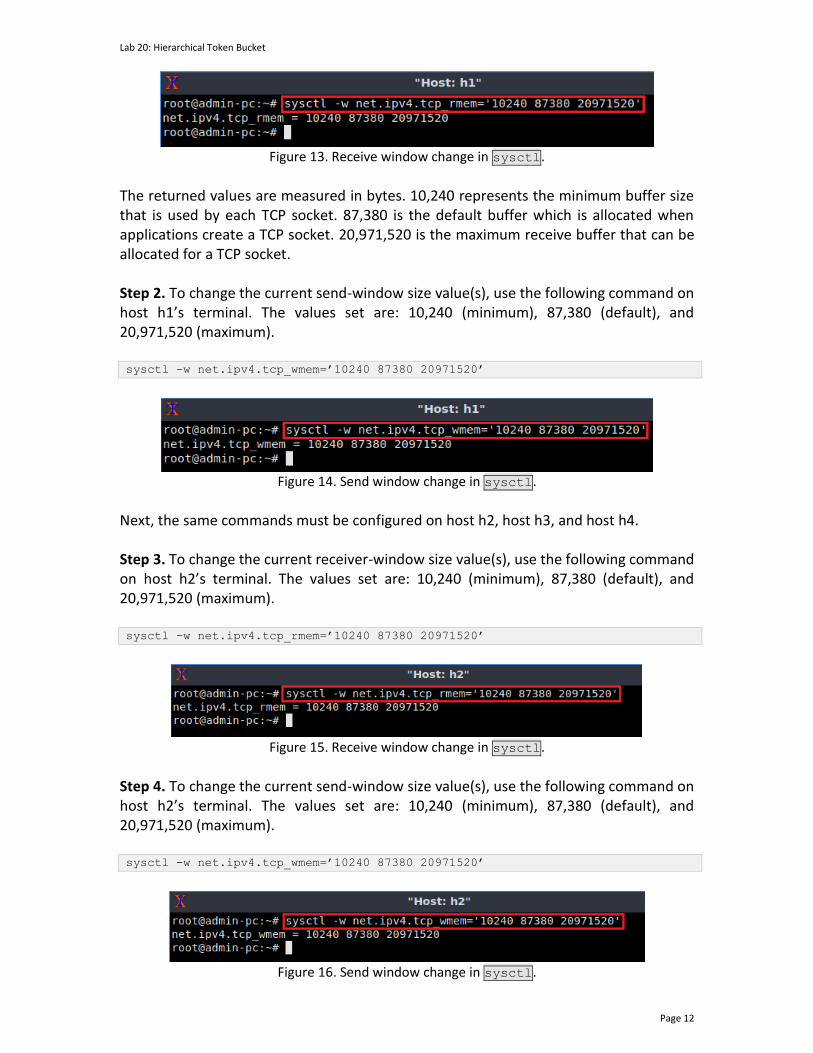
The returned values are measured in bytes. 10,240 represents the minimum buffer size that is used by each TCP socket. 87,380 is the default buffer which is allocated when applications create a TCP socket. 20,971,520 is the maximum receive buffer that can be allocated for a TCP socket. Step 2. To change the current send-window size value(s), use the following command on host h1’s terminal. The values set are: 10,240 (minimum), 87,380 (default), and 20,971,520 (maximum). sysctl -w net.ipv4.tcp_wmem=’10240 87380 20971520’
Figure 14. Send window change in sysctl.
Next, the same commands must be configured on host h2, host h3, and host h4. Step 3. To change the current receiver-window size value(s), use the following command on host h2’s terminal. The values set are: 10,240 (minimum), 87,380 (default), and 20,971,520 (maximum). sysctl -w net.ipv4.tcp_rmem=’10240 87380 20971520’
Figure 15. Receive window change in sysctl.
Step 4. To change the current send-window size value(s), use the following command on host h2’s terminal. The values set are: 10,240 (minimum), 87,380 (default), and 20,971,520 (maximum). sysctl -w net.ipv4.tcp_wmem=’10240 87380 20971520’
Figure 16. Send window change in sysctl.

Lab 20: Hierarchical Token Bucket
Page 13
Step 5. To change the current receiver-window size value(s), use the following command on host h3’s terminal. The values set are: 10,240 (minimum), 87,380 (default), and 20,971,520 (maximum). sysctl -w net.ipv4.tcp_rmem=’10240 87380 20971520’
Figure 17. Receive window change in sysctl.
Step 6. To change the current send-window size value(s), use the following command on host h3’s terminal. The values set are: 10,240 (minimum), 87,380 (default), and 20,971,520 (maximum). sysctl -w net.ipv4.tcp_wmem=’10240 87380 20971520’
Figure 18. Send window change in sysctl.
Step 7. To change the current receiver-window size value(s), use the following command on host h4’s terminal. The values set are: 10,240 (minimum), 87,380 (default), and 20,971,520 (maximum). sysctl -w net.ipv4.tcp_rmem=’10240 87380 20971520’
Figure 19. Receive window change in sysctl.
Step 8. To change the current send-window size value(s), use the following command on host h4’s terminal. The values set are: 10,240 (minimum), 87,380 (default), and 20,971,520 (maximum). sysctl -w net.ipv4.tcp_wmem=’10240 87380 20971520’
Figure 20. Send window change in sysctl.

Lab 20: Hierarchical Token Bucket
Page 14
3.3 Setting switch S1’s buffer size to BDP
In this section, you are going to set switch S1’s buffer size to BDP and emulate a 1 Gbps Wide Area Network (WAN) using the Token Bucket Filter. Then, you will set the TCP sending and receiving windows in all hosts. Finally, you will conduct a throughput test with two TCP competing flows. Step 1. Apply tbf rate limiting rule on switch S2’s s1-eth1 interface. In the client’s terminal, type the command below. When prompted for a password, type password and hit Enter.
• rate: 1gbit
• burst: 500,000
• limit: 2,621,440 sudo tc qdisc add dev s1-eth1 parent 1: handle 2: tbf rate 1gbit burst 500000
limit 2621440
Figure 21. Limiting rate to 1 Gbps and setting the buffer size to BDP on switch S1’s interface.
3.4 Throughput tests of two TCP competing flows
Step 1. Launch iPerf3 in server mode on host h3’s terminal. iperf3 -s
Figure 22. Starting iPerf3 server on host h3.
Step 2. Launch iPerf3 in server mode on host h4’s terminal. iperf3 -s

Lab 20: Hierarchical Token Bucket
Page 15
Figure 23. Starting iPerf3 server on host h4.
The following steps are aimed to replicate the case when two TCP flows are competing sharing the same link therefore, the iperf3 commands in host h1 and host h2 should be executed almost simultaneously. Hence, you will type the commands presented in Step 3 and Step 4 without executing them next, in Step 5 you will press Enter in host h1 and host h2 to execute them.
Step 3. Type the following iPerf3 command in host h1’s terminal without executing it. iperf3 -c 10.0.0.3 -t 60
Figure 24. Running iPerf3 client on host h1.
Step 4. Type the following iPerf3 command in host h2’s terminal without executing it. iperf3 -c 10.0.0.4 -t 60
Figure 25. Running iPerf3 client on host h2.
Step 5. Press Enter to execute the commands shown in step 4 and step 6, first in host h1 terminal then, in host h3 terminal. Step 6. Wait until the test finishes then, click on host h1 terminal to visualize the results. You will notice that host h1 uses approximately the half part of the link (~500Mbps).

Lab 20: Hierarchical Token Bucket
Page 16
Figure 25. Throughput report on host h1.
Step 7. To visualize the results in the other sender, click on host h2 terminal. You will notice that host h2 uses approximately the half part of the link (~500Mbps).
Figure 26. Throughput report on host h2.
Step 8. To stop iperf3 servers in host h3 and host h4 press Ctrl+c.

Lab 20: Hierarchical Token Bucket
Page 17
4 Setting HTB at switch s2 egress interface In this section you will enable in switch S2’s s2-eth2 interface Hierarchical Token Bucket (HTB). First htb is defined as the root queueing discipline. Secondly, two classes are defined. These classes specify the bandwidth allocation for two TCP flows. Then, you will use filters to associate specific flows to the previously defined classes. Lastly, a throughput test is conducted to observe how HTB classifies TCP traffic. HTB ensures that the amount of service provided to each class is at least the minimum of the amount it requests, and the amount assigned to it. Step 1: In order to enable htb in switch S2 egress interface, type the following command: sudo tc qdisc add dev s2-eth2 root handle 1: htb
Figure 26. Setting htb in switch S2’s s2-eth2 interface.
4.1 Defining classes
In this section, first you will define a root class which specifies htb as its parent. A root class, like other classes under an htb qdisc allows its children to borrow from each other, but one root class cannot borrow from another. Then, you will create two classes that will allocate 700Mbps and 300Mbps of bandwidth respectively. These classes borrow from the root the bandwidth they need. Step 1: To define the root class type the following command in the Client’s terminal.
• rate: 1gbit
• ceil: 1gbit sudo tc class add dev s2-eth2 parent 1:0 classid 1:1 htb rate 1gbit ceil 1gbit
Figure 27. Defining a root class.

Lab 20: Hierarchical Token Bucket
Page 18
Step 2: Define the following class by issuing the command shown below:
• rate: 700mbit
• ceil: 1gbit sudo tc class add dev s2-eth2 parent 1:1 classid 1:10 htb rate 700mbit ceil
1gbit
Figure 28. Defining a class rate and ceil values.
Step 3: Define the next class by issuing the following command:
• rate: 300mbit
• ceil: 1gbit sudo tc class add dev s2-eth2 parent 1:1 classid 1:20 htb rate 300mbit ceil
1gbit
Figure 29. Defining a class rate and ceil values.
4.2 Defining filters
In this section, you will specify the filters. The filters determine which class belong to each packet. In this case we use the source IP to match the flows. Note that the IP address of host h1 is 10.0.0.1 and the IP address of host h2 is 10.0.0.2. Step 1: To define filter related to the first class that was defined in the previous section, in the Client’s terminal type the following command: sudo tc filter add dev s2-eth2 protocol ip parent 1:0 prio 1 u32 match ip src
10.0.0.1 flowid 1:10

Lab 20: Hierarchical Token Bucket
Page 19
Figure 30. Setting a filter to associate the flows from h1 to class 1:10.
Step 2 To define filter for the first class type the following command in the Client’s terminal. sudo tc filter add dev s2-eth2 protocol ip parent 1:0 prio 1 u32 match ip src
10.0.0.2 flowid 1:20
Figure 31. Setting a filter to associate the flows from h2 to class 1:20.
4.3 Throughput tests of two TCP competing flows using HTB
In this section, you will conduct a throughput test to verify the previous configuration. Step 1. Launch iPerf3 in server mode on host h3’s terminal. iperf3 -s
Figure 32. Starting iPerf3 server on host h3.
Step 2. Launch iPerf3 in server mode on host h4’s terminal. iperf3 -s
Figure 33. Starting iPerf3 server on host h4.

Lab 20: Hierarchical Token Bucket
Page 20
The following steps are aimed to replicate the case when two TCP flows are competing sharing the same link therefore, the iperf3 commands in host h1 and host h2 should be executed almost simultaneously. Hence, you will type the commands presented in Step 3 and Step 4 without executing them next, in Step 5 you will press Enter in host h1 and host h2 to execute them.
Step 3. Type the following iPerf3 command in host h1’s terminal without executing it. iperf3 -c 10.0.0.3 -t 60
Figure 34. Running iPerf3 client on host h1.
Step 4. Type the following iPerf3 command in host h2’s terminal without executing it. iperf3 -c 10.0.0.4 -t 60
Figure 35. Running iPerf3 client on host h1.
Step 5. Press Enter to execute the commands shown in step 4 and step 6, first in host h1 terminal then, in host h3 terminal. Step 6. Wait until the test finishes then, click on host h1 terminal to visualize the results. You will notice that host h1 uses the bandwidth that was specified by the rate in the first class, which is approximately 700Mbps.

Lab 20: Hierarchical Token Bucket
Page 21
Figure 36. Throughput report on host h1.
Step 7. Click on host h2 terminal to visualize the results. Notice that host h2 uses the bandwidth that was specified by the rate in the second class, which is around 300Mbps.
Figure 37. Throughput report on host h2.
Step 8. To stop iperf3 servers in host h3 and host h4 press Ctrl+c. This concludes Lab 20. Stop the emulation and then exit out of MiniEdit.

Lab 20: Hierarchical Token Bucket
Page 22
References
1. C. H Lee, K. Young-Tak. "QoS-aware hierarchical token bucket (QHTB) queuing disciplines for QoS-guaranteed Diffserv provisioning with optimized bandwidth utilization and priority-based preemption." International conference on information networking 2013 (ICOIN), pp. 351-358. IEEE, 2013.
2. M. Devera “HTB Linux queuing discipline manual - user guide” 2002. [Online]. Available: http://luxik.cdi.cz/~devik/qos/htb/manual/userg.htm.
3. J. Kurose, K. Ross, “Computer networking, a top-down approach,” 7th Edition, Pearson, 2017.
4. C. Villamizar, C. Song, “High performance TCP in ansnet,” ACM Computer Communications Review, vol. 24, no. 5, pp. 45-60, Oct. 1994.
5. R. Bush, D. Meyer, “Some internet architectural guidelines and philosophy,” Internet Request for Comments, RFC Editor, RFC 3439, Dec. 2003. [Online]. Available: https://www.ietf.org/rfc/rfc3439.txt.
6. J. Gettys, K. Nichols, “Bufferbloat: dark buffers in the internet,” Communications of the ACM, vol. 9, no. 1, pp. 57-65, Jan. 2012.
7. N. Cardwell, Y. Cheng, C. Gunn, S. Yeganeh, V. Jacobson, “BBR: congestion-based congestion control,” Communications of the ACM, vol 60, no. 2, pp. 58-66, Feb. 2017.