Lab 2 Updated1
22
Table of Content _____________________________________________ _________ Summary/Abstract 2 Introduction and Objective 2 Theory 3 Description of Equipment Apparatus 4 Procedure 4 Data, Observations and Results 6 Analysis and Discussions 8 Discussions 13 Conclusions 15 References 15 Appendix 16 1
-
Upload
feezah-hanimoon -
Category
Documents
-
view
124 -
download
4
Transcript of Lab 2 Updated1
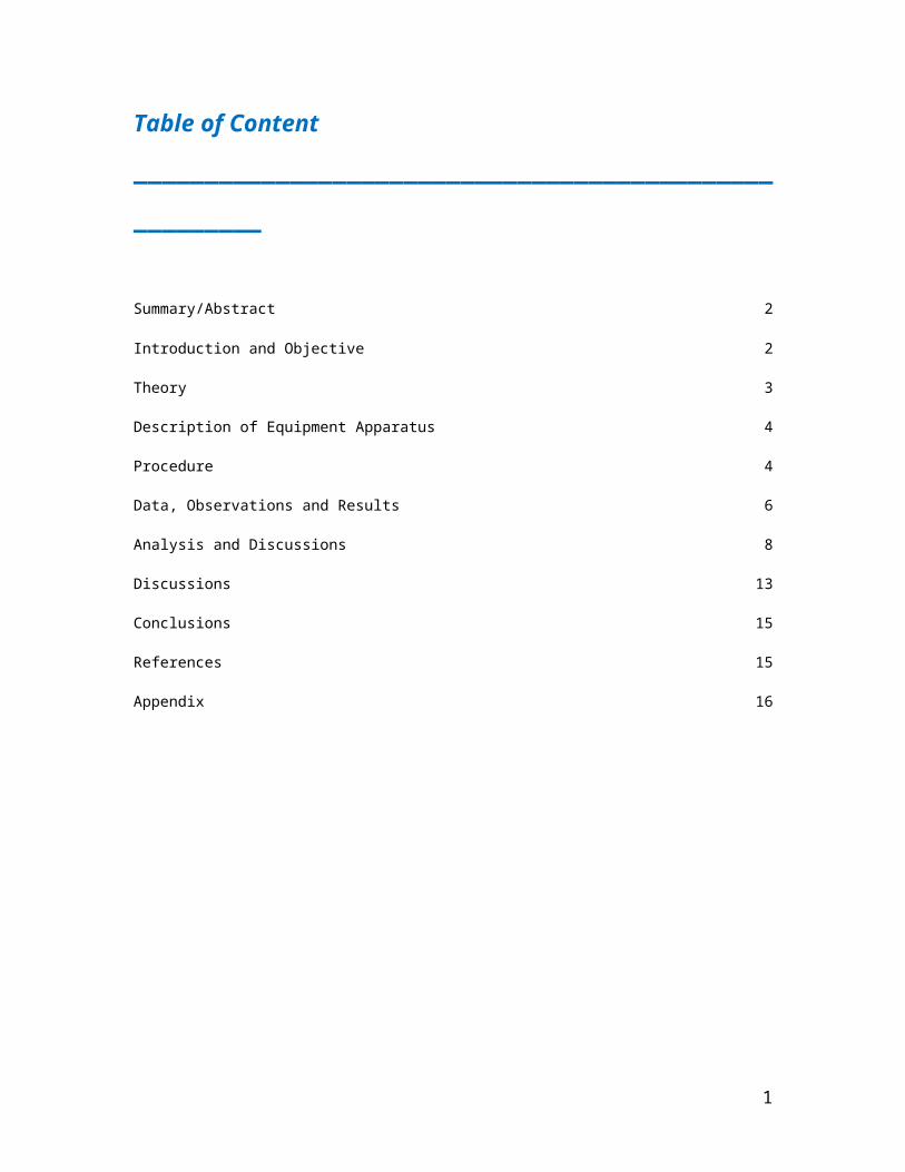
Table of Content
______________________________________________________
Summary/Abstract 2
Introduction and Objective 2
Theory 3
Description of Equipment Apparatus 4
Procedure 4
Data, Observations and Results 6
Analysis and Discussions 8
Discussions 13
Conclusions 15
References 15
Appendix 16
1
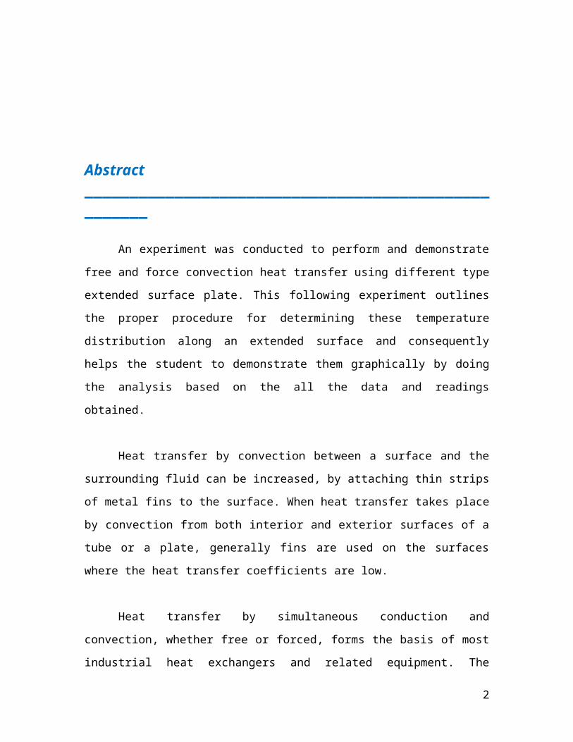
Abstract____________________________________________________
An experiment was conducted to perform and demonstrate free and force
convection heat transfer using different type extended surface plate. This following
experiment outlines the proper procedure for determining these temperature distribution
along an extended surface and consequently helps the student to demonstrate them
graphically by doing the analysis based on the all the data and readings obtained.
Heat transfer by convection between a surface and the surrounding fluid can be
increased, by attaching thin strips of metal fins to the surface. When heat transfer takes
place by convection from both interior and exterior surfaces of a tube or a plate, generally
fins are used on the surfaces where the heat transfer coefficients are low.
Heat transfer by simultaneous conduction and convection, whether free or forced,
forms the basis of most industrial heat exchangers and related equipment. The
measurement and prediction of heat transfer coefficients for such circumstances is
achieved in the free and forced convection heat transfer apparatus by studying the
temperature profiles and heat flux in an air duct with associated flat and extended transfer
surfaces.
Introduction and Objectives______________________________________________________
In this particular laboratory experiment, students are required to demonstrate the
use of extended surfaces to improve heat transfer from a surface and to demonstrate
convection heat transfer by using different type of extended surface. Besides that, the
temperature distribution along an extended surface is also to be determined at the end of
the experiment.
In addition to that, this experiment is also useful in such a way that it helps to
provide some exposure to the students so that they are able to interpret the obtained test
data and at the same time are able to apply the theory they have learned in class.
2
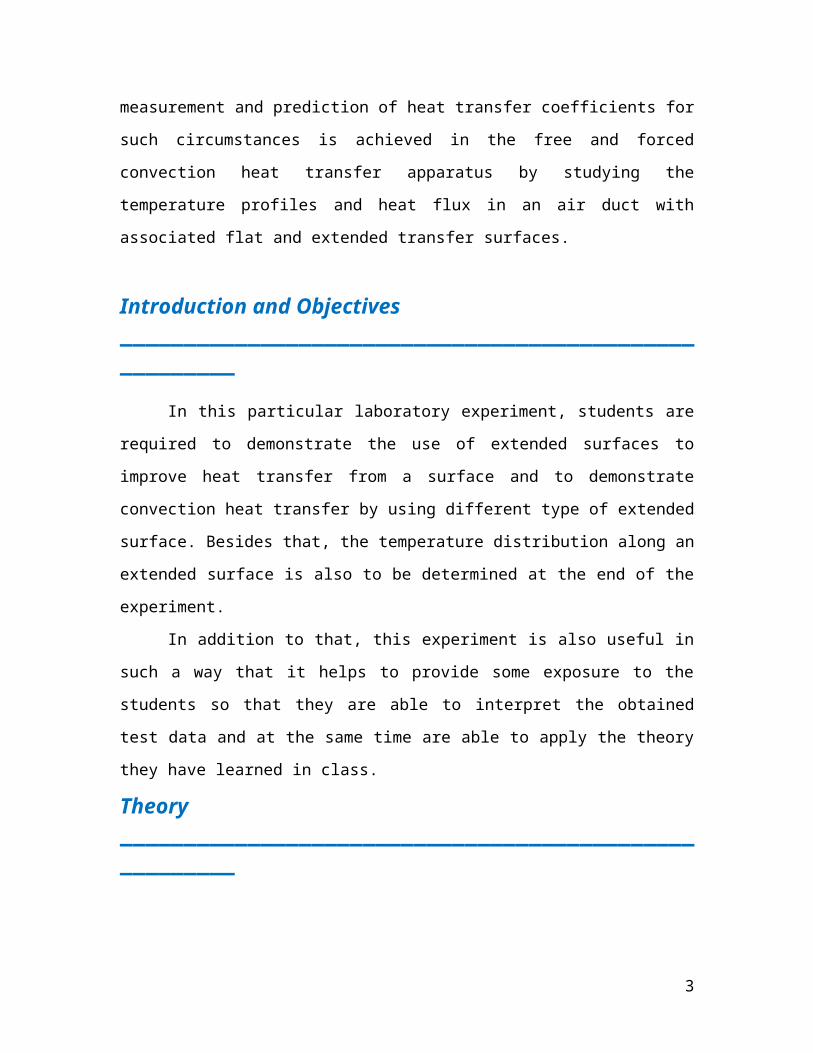
Theory______________________________________________________
A heated surface dissipates heat to the surrounding fluid primarily through a
process called convection. Heat is also dissipated by conduction and radiation, however
these effects are not considered in this experiment. Air in contact with the hot surface is
heated by the surface and rises due to reduction in density. The heated air is replaced by
cooler air, which is in turn heated by the surface, and rises. This process is called free
convection.
In free convection small movements of air generated by this heat limit the heat
transfer rate from the surface. Therefore more heat is transfer if the velocity is increase
over the heated surface. This process of assisting the movement of air over the heated
surface is called forced convection. A heated surface experiencing forced convection will
have a lower surface temperature than that of the same surface in free convection, for the
same power input.
Convection heat transfer from an object can be improved by increasing the
surface area in contact with the air. In practical it may be difficult to increase the size of
the body to suit. In these circumstances the surface area in contact with the air may be
increased by adding fins or pins normal to the surface. These features are called extended
surfaces. A typical example is the use of fins on the cylinder and head on an air-cooled
petrol engine. The effect of extended surfaces can be demonstrated by comparing finned
and pinned surfaces with a flat under the same conditions of power input and airflow.
3
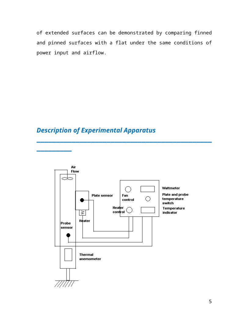
Description of Experimental Apparatus______________________________________________________
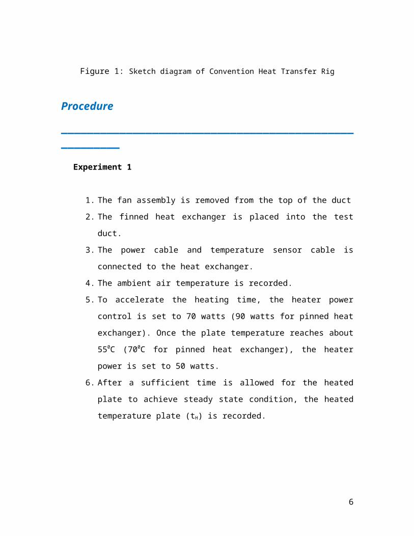
Figure 1: Sketch diagram of Convention Heat Transfer Rig
Procedure
______________________________________________________
Experiment 1
1. The fan assembly is removed from the top of the duct
2. The finned heat exchanger is placed into the test duct.
3. The power cable and temperature sensor cable is connected to the heat
exchanger.
4. The ambient air temperature is recorded.
4
5. To accelerate the heating time, the heater power control is set to 70 watts (90
watts for pinned heat exchanger). Once the plate temperature reaches about
550C (700C for pinned heat exchanger), the heater power is set to 50 watts.
6. After a sufficient time is allowed for the heated plate to achieve steady state
condition, the heated temperature plate (tH) is recorded.
7. The distance of the access holes on the pinned and finned heat exchanger is
measured from the black plate.
8. The temperature probe is inserted into the duct through the hole nearest to the
heated plate, T1, ensuring that the tip of the probe is in contact with the pin.
9. The temperature of the next two holes on the fins. (T2 and T3) are measured.
Experiment 2
1. The fan assembly is placed on to the top of duct.
2. Insert the temperature probe is inserted into the duct through the hole nearest
the heated plate, T1, ensuring that the tip of the probe is in contact with the pin
3. The fan speed control is set to low speed.
4. After the temperature has achieve steady state condition (~3 minutes), the
temperature probe reading is noted
5. This procedure is repeated at medium and maximum speed
6. The finned heat exchanger is removed and is then replaced with the pinned
heat exchanger.
5
Data and Observations
______________________________________________________
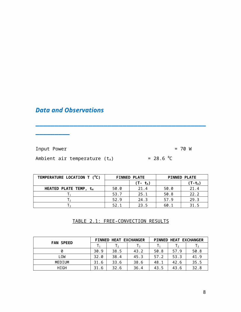
Input Power = 70 W
Ambient air temperature (tA) = 28.6 0C
TEMPERATURE LOCATION T (0C) FINNED PLATE PINNED PLATE(T- tA) (T-tA)
HEATED PLATE TEMP, tH 50.0 21.4 50.0 21.4T1 53.7 25.1 50.8 22.2T2 52.9 24.3 57.9 29.3T3 52.1 23.5 60.1 31.5
TABLE 2.1: FREE-CONVECTION RESULTS
FAN SPEEDFINNED HEAT EXCHANGER PINNED HEAT EXCHANGER
T1 T2 T3 T1 T2 T3
0 30.9 38.5 43.2 50.8 57.9 50.8LOW 32.0 38.4 45.3 57.2 53.3 41.9
MEDIUM 31.6 33.6 38.6 48.1 42.6 35.5HIGH 31.6 32.6 36.4 43.5 43.6 32.8
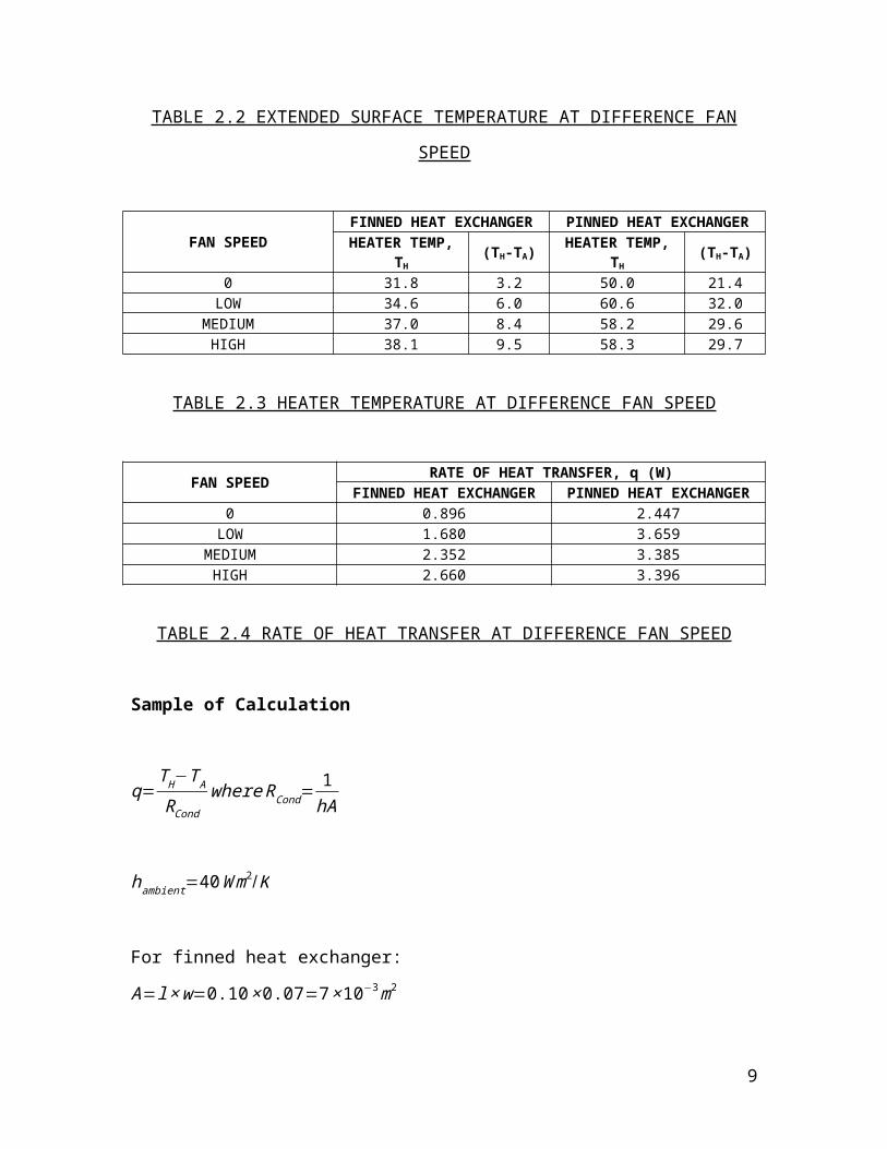
TABLE 2.2 EXTENDED SURFACE TEMPERATURE AT DIFFERENCE FAN
SPEED
FAN SPEEDFINNED HEAT EXCHANGER PINNED HEAT EXCHANGERHEATER TEMP,
TH(TH-TA)
HEATER TEMP, TH
(TH-TA)
0 31.8 3.2 50.0 21.4LOW 34.6 6.0 60.6 32.0
MEDIUM 37.0 8.4 58.2 29.6HIGH 38.1 9.5 58.3 29.7
TABLE 2.3 HEATER TEMPERATURE AT DIFFERENCE FAN SPEED
FAN SPEEDRATE OF HEAT TRANSFER, q (W)
FINNED HEAT EXCHANGER PINNED HEAT EXCHANGER0 0.896 2.447
LOW 1.680 3.659MEDIUM 2.352 3.385
HIGH 2.660 3.396
6
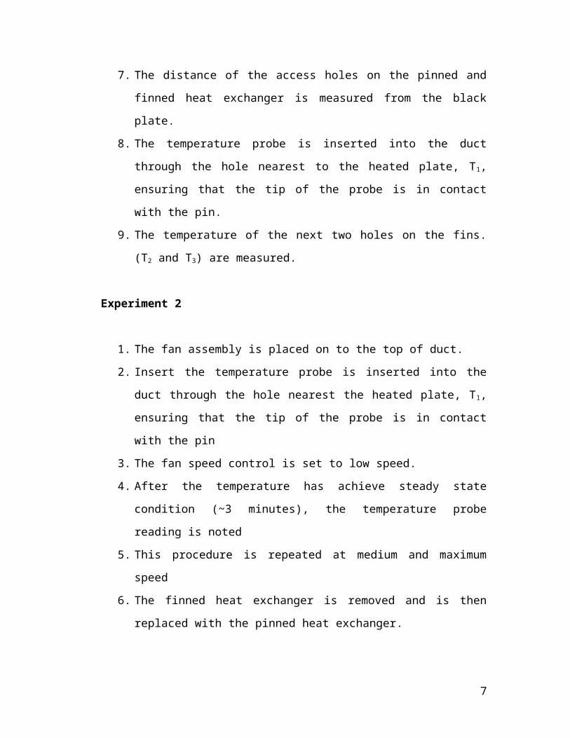
TABLE 2.4 RATE OF HEAT TRANSFER AT DIFFERENCE FAN SPEED
Sample of Calculation
q=T H−T ARCond
whereRCond=1hA
hambient=40Wm2/K
For finned heat exchanger:
A=l×w=0.10×0.07=7×10⁻³m2
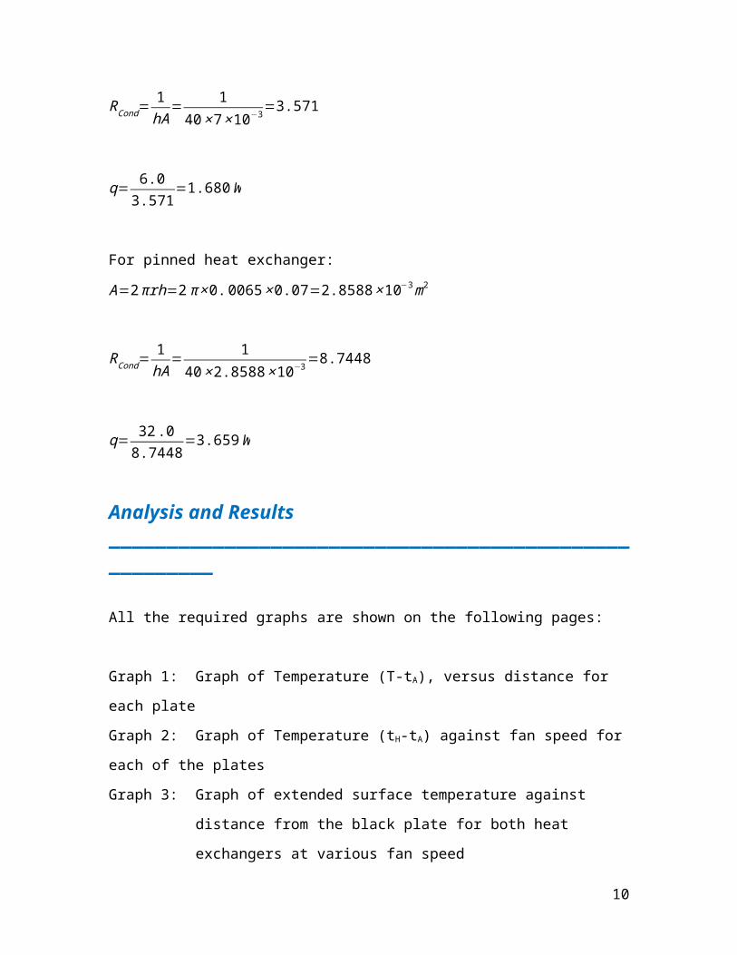
RCond=1hA
= 1
40×7×10−3=3.571
q= 6.03.571
=1.680W
For pinned heat exchanger:
A=2πrh=2π ×0. 0065×0.07=2.8588×10⁻³m2
RCond=1hA
= 1
40×2.8588×10−3=8.7448
q= 32 .08.7448
=3.659W
Analysis and Results______________________________________________________
All the required graphs are shown on the following pages:
7
Graph 1: Graph of Temperature (T-tA), versus distance for each plate
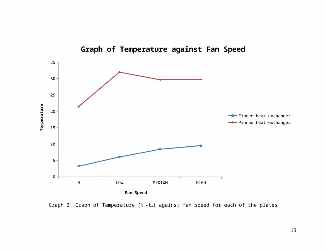
Graph 2: Graph of Temperature (tH-tA) against fan speed for each of the plates
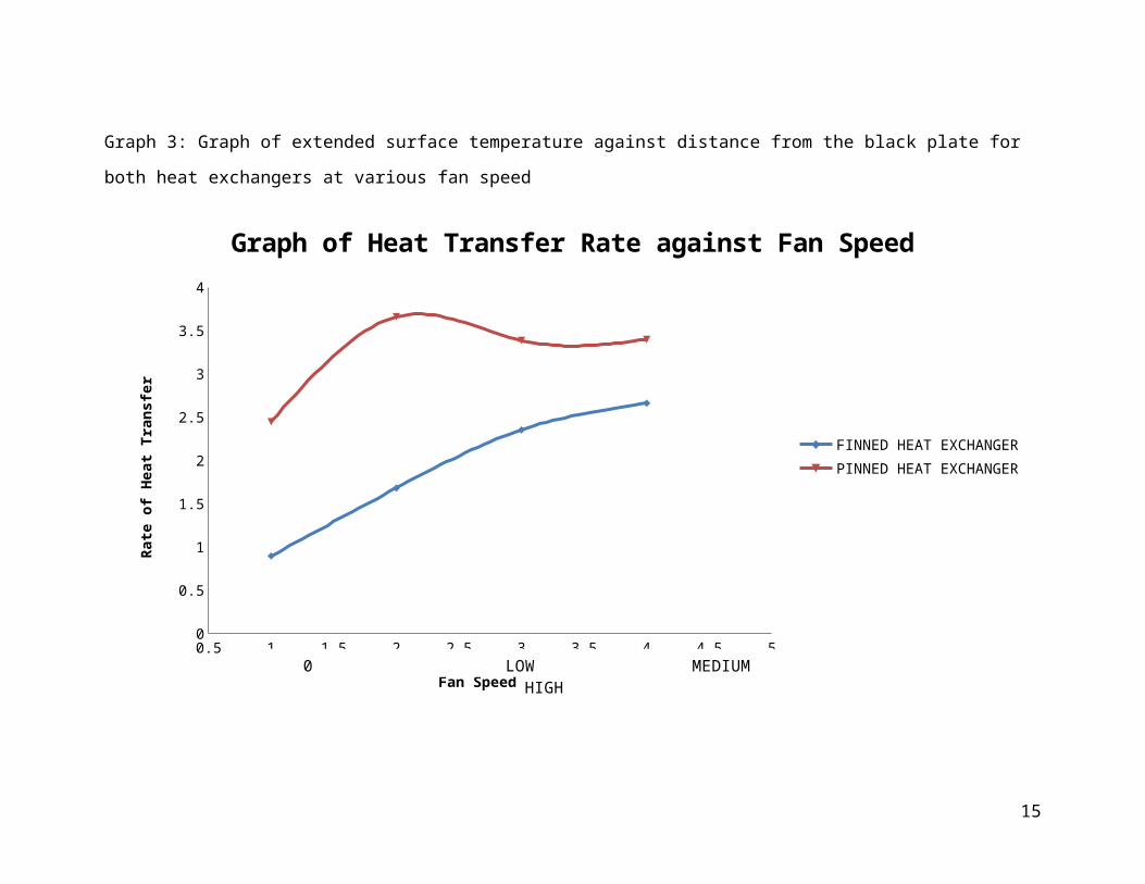
Graph 3: Graph of extended surface temperature against distance from the black
plate for both heat exchangers at various fan speed
Graph 4: Graph of heat transfer rate against fan speed for both exchangers
8
heated plate temp. t1 T2 T30
5
10
15
20
25
30
35
Graph of Temperature against Distance
Finned platePinned plate
Distance
Tem
pera
ture
Graph 1: Graph of Temperature (T-tA), versus distance for each plate
9
0 LOW MEDIUM HIGH0
5
10
15
20
25
30
35
Graph of Temperature against Fan Speed
Finned heat exchangerPinned heat exchanger
Fan Speed
Tem
pera
ture
Graph 2: Graph of Temperature (tH-tA) against fan speed for each of the plates
10

0 LOW MEDIUM HIGH0
10
20
30
40
50
60
70
Graph of Extended Surface against Temperature.
T1 (finned)T2 (finned)T3 (finned)T1 (pinned)T2(pinned)T3(pinned)
Extendard Surface
Tem
pera
ture
Graph 3: Graph of extended surface temperature against distance from the black plate for both heat exchangers at various fan speed
11

0.5 1 1.5 2 2.5 3 3.5 4 4.5 50
0.5
1
1.5
2
2.5
3
3.5
4
Graph of Heat Transfer Rate against Fan Speed
FINNED HEAT EXCHANGERPINNED HEAT EXCHANGER
Fan Speed
Rate
of H
eat T
rans
fer
0 LOW MEDIUM HIGH
Graph 4: Graph of heat transfer rate against fan speed for both exchangers
12
Discussions______________________________________________________
Data and Graph Analysis
From Data, Observation and Results section of this report, we had plotted the
graph where we can see the relationship between the temperature and distance for each
plate. From Graph 1, for a finned plate, initially when we heated the plate the temperature
is increase. After a few moment, the temperature drop linearly until T3 distance. On the
other hand, for the pinned plate the temperature increases constantly until T3.
As for Graph 2, it can clearly be shown we can see that pinned heat exchanger
have high temperature difference compared to finned heat exchanger. This indicates that,
pinned plate release less heat compare to finned plate.
Besides that, we can come up with a few relationships by observing the pattern of
the curves illustrates by Graph 3. For both pinned and finned heat exchanger, at position
T2 and T3, the temperature seems to be decreasing as the speed of the fan increases. In
contrary, at position T1, as the speed of the fan went up from 0 to the highest speed, the
temperature for finned heat exchanger increases while for pinned heat exchanger, the
temperature decreases.
Comments on the correlation between total surface area of the heat exchanger and the
temperature achieved and which of the extended surfaces has greater surface area.
For finned plate, it is square in shape. The heat release from the plate is high, and
thus the temperature stored is low. On the other hand, for pinned plate, it is cylinder in
shape. The heat release from the plate is low compared to finned plate. Thus, the
temperature stored in the pinned plate is high.
13

For a heat exchanger with 100 % efficiency, the whole of the extended surface should be
at the same temperature as the backplane, why this is not achievable in the experiment?
According to thermodynamic law of conduction of heat transfer, total amount of
energy transferred will not be 100 % efficiency because they will be have some minor
loses during the heat conduction. Technically, when the heat is transferred from one
medium to another, there will be some friction that will cause some significant heat
losses.
Which extended surface have higher heat transfer rate? Why?
Pinned plate have high heat transfer rate. It is because it is cylinder in shape. The
cylinder shape basically made the pinned plate released heat in slow rate.
14
Conclusions
______________________________________________________
From this experiment, we can see that the use of extended surfaces enhance heat
transfer from a surface. It is found that finned extended surface releases heat faster than
pinned extended surface due to higher surface area.
In theory, higher flow velocity would encourage convection heat transfer. This
theory is clearly illustrated in Graph 4 where rate of heat transfer increases as the fan
speed increases.
Generally, the temperature decreases as we measure from position 1 to 3. This
temperature distribution pattern is depicted in Graph 3. However, discrepancy may occur
due to some errors. For instance, the inconsistency of the fan speed that caused by worn
out equipment may greatly affect the entire experiment.
In conclusion, this experiment can be consider as successful since all the
objectives have been covered.
References
______________________________________________________
Instruction manual from the Heat Transfer & Applied Thermodynamics Lab
2012, Convection Heat Transfer,
http://www.engineeringtoolbox.com/convective-heat-transfer-d_430.html
2012, Wikipedia, Convection
http://en.wikipedia.org/wiki/Convection
2012, Wikipedia, Heat Exchanger
http://en.wikipedia.org/wiki/Heat_exchanger
15
2012, The theory behind heat transfer
http://www.distributionchalinox.com/produits/alfa-laval/echangeurs/heat-transfer-
brochure.pdf
Incropera, DeWitt, Bergmann, Lavine, Fundamentals of Heat and Mass Transfer, 7 th
Edition, Wiley Asia Student Edition
Yunus A. Cengel, Michael A. Boles, Thermodynamics An Engineering Approach, 7th
Edition, Mc Graw Hill
Appendix______________________________________________________
Finned Extended Surface
16