Lab 10 - Geometrical Opticspeople.virginia.edu/~ecd3m/2419/Fall2011/manual/Lab10.pdfLab 10 -...
22
L10-1 University of Virginia Physics Department PHYS 2419, Fall 2011 Name Date Partners Lab 10 - GEOMETRICAL OPTICS OBJECTIVES • To examine Snell’s Law. • To observe total internal reflection. • To understand and use the lens equations. • To find the focal length of a converging lens. • To discover how lenses form images. • To observe the relationship between an object and the image formed by a lens. • To discover how a telescope works. OVERVIEW Light is an electromagnetic wave. The theory of the propagation of light and its interactions with matter is by no means trivial; nevertheless, it is possible to understand most of the fundamental features of optical instruments such as eyeglasses, cameras, microscopes, telescopes, etc. through a simple theory based on the idealized concept of a light ray. A light ray is a thin “pencil” of light that travels along a straight line until it encounters matter, at which point it is reflected, refracted, or absorbed. The thin red beam from a laser pointer is a good approximation of such a ray. The study of light rays leads to two important experimental observations: 1. When a light ray is reflected by a plane surface, the angle of reflection θ 2 equals the angle of incidence θ 1 , as shown in Figure 1. θ 2 θ 1 Figure 1 Reflection: θ 1 = θ 2 2. When a light ray travels from one transparent medium into another, as shown in Figure 2, the ray is generally “bent”
Transcript of Lab 10 - Geometrical Opticspeople.virginia.edu/~ecd3m/2419/Fall2011/manual/Lab10.pdfLab 10 -...

L10-1
University of Virginia Physics Department PHYS 2419, Fall 2011
Name Date Partners
Lab 10 - GEOMETRICAL OPTICS
OBJECTIVES
• To examine Snell’s Law.
• To observe total internal reflection.
• To understand and use the lens equations.
• To find the focal length of a converging lens.
• To discover how lenses form images.
• To observe the relationship between an object and the image formed by a lens.
• To discover how a telescope works.
OVERVIEW
Light is an electromagnetic wave. The theory of the propagation
of light and its interactions with matter is by no means trivial;
nevertheless, it is possible to understand most of the fundamental
features of optical instruments such as eyeglasses, cameras,
microscopes, telescopes, etc. through a simple theory based on the
idealized concept of a light ray.
A light ray is a thin “pencil” of light that travels along a straight
line until it encounters matter, at which point it is reflected,
refracted, or absorbed. The thin red beam from a laser pointer is a
good approximation of such a ray. The study of light rays leads to
two important experimental observations:
1. When a light ray is reflected by a plane surface, the angle of
reflection θ2 equals the angle of incidence θ1, as shown in
Figure 1.
θ2
θ1
Figure 1 Reflection: θ1 = θ2
2. When a light ray travels from one transparent medium into
another, as shown in Figure 2, the ray is generally “bent”

L10-2 Lab 10 - Geometrical Optics
University of Virginia Physics Department PHYS 2419, Fall 2011
(refracted). The directions of propagation of the incident and
refracted rays are related to each other by Snell’s Law:
1 1 2 2sin sinn nθ θ= (1)
where the dimensionless number n is called the index of refraction and is characteristic of the material.
θ1
n1 n2
θ2
Figure 2 Refraction: 1 1 2 2sin sinn nθ θ=
Note that if 1 1 2sinn nθ > , no solution is possible for 2sinθ . In this
case, none of the light will pass through the interface. All of the light will be reflected. This total internal reflection is more
perfect than reflection by any metallic mirror.
Most transparent materials have indices of refraction between 1.3
and 2.0. The index of refraction of a vacuum is by definition unity. For most purposes, the index of refraction of air (nair = 1.0003) can
also be taken as unity.
Accurate measurements show the index of refraction to be a
function of the wavelength and thus of the color of light. For most materials, one finds that:
redblue
nn > (2)
A simplified theoretical explanation of these observations is given by Huygens’ Principle, which is discussed in elementary physics
texts.
Note: The room lights will be turned out for these investigations. It will sometimes be difficult to read and write in this manual. Use
the desk lamp as needed. Be patient!

Lab 10 - Geometrical Optics L10-3
University of Virginia Physics Department PHYS 2419, Fall 2011
INVESTIGATION 1: SNELL’S LAW
In this investigation, you will observe and verify Snell’s Law by using both a rectangular block and a prism. You will also observe
total internal reflection in a prism.
You will need the following materials:
• Rectangular block made of Lucite
• Triangular prism made of Lucite
• Triangle
• Protractor
• Light ray box
• Graphing paper from roll (approximately 40 cm each for Activities 1-1 and 1-2).
Activity 1-1: Verifying Snell’s Law
In this activity, you will verify Snell’s Law by using the light ray box with a single ray and the rectangular plastic block.
PLEASE TAKE CARE NOT TO SCRATCH THIS BLOCK
OR THE OTHER OPTICAL ELEMENTS!
θ1
θ1'
θ2
θ2'
t
s
Figure 3 Plate with parallel surfaces.
From Figure 3 we can see that Snell’s Law and the symmetry of the geometry imply (assuming nair ≈ 1):
1 2
sin sinn θ θ= (3)
1 1'θ θ= (4)

L10-4 Lab 10 - Geometrical Optics
University of Virginia Physics Department PHYS 2419, Fall 2011
and
( )1 2 2sin coss t θ θ θ= − (5)
1. Using the single aperture mask, let a single ray from the ray box fall on a piece of graph paper such that it is aligned with the
grid. [It may help to tape the paper to the table to keep it from moving.]
Note: Only one diagram will be drawn for each group. There are at least three activities that have you draw light rays, so make sure
each partner does at least one ray tracing diagram.
2. Place the block on the graph paper. Make sure that there is at least 10 cm of paper on either side of the block. Align the block
so that the light ray is incident at an oblique angle with the block (as in Figure 3). Trace the outline of the block on the
graph paper.
Hint: Larger values of θ1 produce better results.
3. Mark on the graph paper the entry and exit points of the light. Also mark points on the incident and exit rays far from block.
This will be necessary to determine the angles.
4. After removing the block, trace the light ray paths and label the
diagram.
5. Use the protractor to measure the angles θ1, θ2, θ1' and θ2
'.
Extrapolate the incident ray so that you can measure s, the “shift” (or offset) of the output ray relative to the incident ray.
Record your results in Table 1-1.
Note: We have used the subscript 1 for air and the subscript 2 for plastic, regardless of the direction of the ray. Other conventions
are equally valid.
Table 1-1
1θ 2θ
1θ ′
2θ ′ s
6. Determine the index of refraction n for the block. Show your work.
n

Lab 10 - Geometrical Optics L10-5
University of Virginia Physics Department PHYS 2419, Fall 2011
Question 1-1: Is Equation (4) satisfied? [In other words, are the incident and exit rays parallel?] Discuss.
Question 1-2: Is Equation (5) satisfied? What does it tell you
about the path of a ray through the center of a thin lens? [Hint: Imagine your Lucite block getting thinner and think about how the
offset between the incident and exit rays would change.]
Activity 1-2: Light Passing Through a Prism
In this activity, you will study the propagation of light through a prism, as well as observe total internal reflection.
Figure 4 Refraction and total reflection in a prism.
Two examples of light propagation in a prism are shown in
Figure 4. As you will recall, at each surface some of the light is reflected and some of the light is refracted. Figure 4a shows a light
ray entering the prism at A at an angle θin (relative to the normal), the refracted ray at the front surface, and the refracted ray at the
rear surface leaving the prism at B at an angle θout. [Note: At each
θin
AB
1refracted 1in
(a) (b)
θout
2reflected 2refracted
AθC
2in α C
D
L10-6 Lab 10 - Geometrical Optics
University of Virginia Physics Department PHYS 2419, Fall 2011
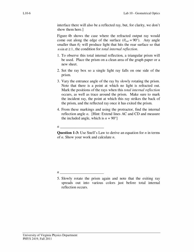
interface there will also be a reflected ray, but, for clarity, we don’t show them here.]
Figure 4b shows the case where the refracted output ray would come out along the edge of the surface (θout = 90°). Any angle
smaller than θC will produce light that hits the rear surface so that
sin 1n α ≥ , the condition for total internal reflection.
1. To observe this total internal reflection, a triangular prism will be used. Place the prism on a clean area of the graph paper or a
new sheet.
2. Set the ray box so a single light ray falls on one side of the
prism.
3. Vary the entrance angle of the ray by slowly rotating the prism.
Note that there is a point at which no light is refracted out. Mark the positions of the rays when this total internal reflection
occurs, as well as trace around the prism. Make sure to mark the incident ray, the point at which this ray strikes the back of
the prism, and the reflected ray once it has exited the prism.
4. From these markings and using the protractor, find the internal
reflection angle α. [Hint: Extend lines AC and CD and measure the included angle, which is α + 90°]
α _______________________
Question 1-3: Use Snell’s Law to derive an equation for n in terms
of α. Show your work and calculate n.
n _______________________
5. Slowly rotate the prism again and note that the exiting ray spreads out into various colors just before total internal
reflection occurs.

Lab 10 - Geometrical Optics L10-7
University of Virginia Physics Department PHYS 2419, Fall 2011
Question 1-4: Why does the light spread into different colors prior to total internal reflection?
6. Start at the point of total internal reflection and rotate the prism
slightly to increase the entrance angle. You should see a weak ray just grazing along the outside of the prism base. Note very
carefully which color emerges outside the prism first (red or blue).
Question 1-5: Discuss what this tells you about the relative magnitudes of nred and nblue for Lucite.
INVESTIGATION 2: CONVERGING LENSES
Most optical instruments contain lenses, which are pieces of glass
or transparent plastics. To see how optical instruments function, one traces light rays through them. We begin with a simple
example by tracing a light ray through a single lens.
We apply Snell’s Law to a situation in which a ray of light, coming
from a medium with the refractive index n1 = 1, e.g. air, falls onto a glass sphere with the index n, shown in Figure 5.
L10-8 Lab 10 - Geometrical Optics
University of Virginia Physics Department PHYS 2419, Fall 2011
F0
h
θ1 n
α
R
f0
x
θ2 y
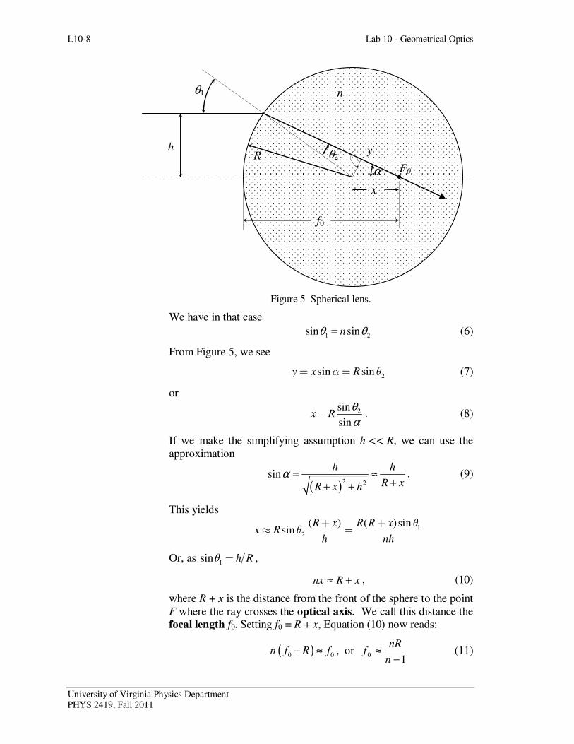
Figure 5 Spherical lens.
We have in that case
1 2sin sinnθ θ= (6)
From Figure 5, we see
2sin siny x Rα θ= = (7)
or
2sin
sinx R
θ
α= . (8)
If we make the simplifying assumption h << R, we can use the
approximation
( )2 2
sinh h
R xR x h
α = ≈++ +
. (9)
This yields
12
( ) sin( )sin
R R xR xx R
h nh
θθ
++≈ =
Or, as 1sin h Rθ = ,
xRnx +≈ , (10)
where R + x is the distance from the front of the sphere to the point
F where the ray crosses the optical axis. We call this distance the focal length f0. Setting f0 = R + x, Equation (10) now reads:
( )0 0n f R f− ≈ , or 1
0−
≈n
nRf (11)

Lab 10 - Geometrical Optics L10-9
University of Virginia Physics Department PHYS 2419, Fall 2011
This is a remarkable result because it indicates that, within the
limits of our approximation ( h << R ), the focal length 0f is
independent of h. This means that all rays that come in parallel to
each other and are close to the axis are collected in one point, the focal point, F0.
Note that our simple theory of a lens applies only to those cases in which the focal point is inside the sphere. A lens whose focal
point is on its inside is not very useful for practical applications; we want it to be on the outside. [Actually, whether inside or out,
spheres, for various reasons, do not make very useful lenses.] We will therefore study a more practical lens, the planoconvex lens.
A planoconvex lens is bounded on one side by a spherical surface with a radius of curvature R and on the other by a plane (see
Figure 6). To keep things simple we make the additional assumption that it is very thin, i.e. that d << R. Now we trace an
arbitrary ray that, after having been refracted by the spherical front surface, makes an angle θ1 with the optical axis, as shown in
Figure 6.
F0
h
θ1
n
α
R
f0
d
f
θ3
F
Figure 6 Focal point of planoconvex lens.
If there were still a full glass sphere, this ray would intersect the
optical axis at the point F0, a distance f0 from the front surface. On encountering the planar rear surface of the lens it will instead,
according to Snell’s Law, be bent to intercept the axis at the point F, a distance f from the front. Behind the rear surface is air,
so, on the encounter with the second surface Snell’s Law becomes:
3sin sinn α θ= (12)

L10-10 Lab 10 - Geometrical Optics
University of Virginia Physics Department PHYS 2419, Fall 2011
But
3sinh
fθ ≈ and
0
sinh
fα ≈ (13)
Hence,
0ffn
≈ , (14)
i.e. in this case the distance f is independent of the distance h (as
long as h << R and d << R). Using Equation (11) in Equation (14)
we find that all incoming rays that are parallel to the optical axis of
a thin planoconvex lens are collected in a focal point at a distance
1−
=n
Rf (15)
behind the lens.
What about rays that are not parallel? One can show that all rays
issuing from the same object point will be gathered in the same
image point (as long as the object is more than one focal length
away from the lens).
To find the image point, we only need consider two rays (we’ll
discuss three that are easy to construct) and find their intersection.
Let us assume that there is a point source of light at the tip of
object O at a distance o > f in front of the lens. Consider the three
rays issuing from this source shown in Figure 7:
f
i o
f
I
O
F F
1
3
2
Figure 7 Image construction.
1. A ray that is parallel to the axis. According to what we have
just learned, it will go through the focal point F behind the
lens.
2. A ray that goes through the focal point F in front of the lens.
With a construction analogous to the one shown in Figure 7, one
can show that light parallel to the axis coming from behind the

Lab 10 - Geometrical Optics L10-11
University of Virginia Physics Department PHYS 2419, Fall 2011
lens will go through the focal point in front. Our construction is
purely geometrical and cannot depend on the direction of the
light beam. We conclude that light that passes through the focal
point in front of the lens must leave the lens parallel to the axis.
This ray will intersect the first ray at the tip of image I at a
distance i behind the lens.
3. A ray that goes through the center of the lens. At the center,
the two glass surfaces are parallel. As we have seen, light
passing through such a plate will be shifted by being bent
towards the normal at the first interface and then back to the
original direction at the second interface. If the plate (in our
case the lens) is thin, the shift will be small. We assumed our
lens was very thin, so we can neglect any such shift.
From Figure 7 it should not be difficult for you to see (from
“similar triangles”) that:
I O I
o f
+= and
I O O
i f
+=
Hence we arrive at the following thin lens formulae:
iof
111+= (16)
O
o
I
i= (17)
We define magnification M to be the ratio of the image size I to
the object size O:
I
MO
≡ (18)
or [by application of Equations (16) and (17)]:
f
Mo f
=−
(19)
The image in Figure 7 is called a real image because actual rays
converge at the image. The method of image construction used in
Figure 7, as well as thin lens formulae, can also be formally
applied to situations where that is not the case.
What about when the object is closer than one focal length? In
Figure 8, an object O is placed within the focal distance ( o f< ) of
a lens. Following the usual procedure, we draw the ray going
through the center of the lens and the one that is parallel to the
axis. We add a third ray, originating from O but going in a

L10-12 Lab 10 - Geometrical Optics
University of Virginia Physics Department PHYS 2419, Fall 2011
direction as if it had come from the first focal point F. All these
are real rays and we draw them as solid lines.
We extend the three lines backward as dashed lines and note that
all three meet in a single point Q in front of the lens. To an
observer behind the lens, the light coming from O will seem to
come from Q and an upright, magnified image of the object O will
be seen. This image is a virtual image and not a real image since
no light actually issues from Q.
Figure 8 Magnifying glass.
By an appropriate choice of notation convention, we can apply the
thin lens formulae to the magnifying glass. By way of a specific
example, setting o = f / 2 in these equations, for instance, yields
i = – f, I = – 2O and M = -2. We interpret the minus sign in the
first equation as meaning that i extends now in front of the lens and
the minus sign in the second that the image is no longer inverted
but upright. We therefore introduce the following convention: o
and i are taken to be positive if the object is to one side and the
image on the other side of the lens. O and I are taken to be
positive if the object is upright and the image is inverted.
Figure 9 Biconcave lens.
-I
Lab 10 - Geometrical Optics L10-13
University of Virginia Physics Department PHYS 2419, Fall 2011
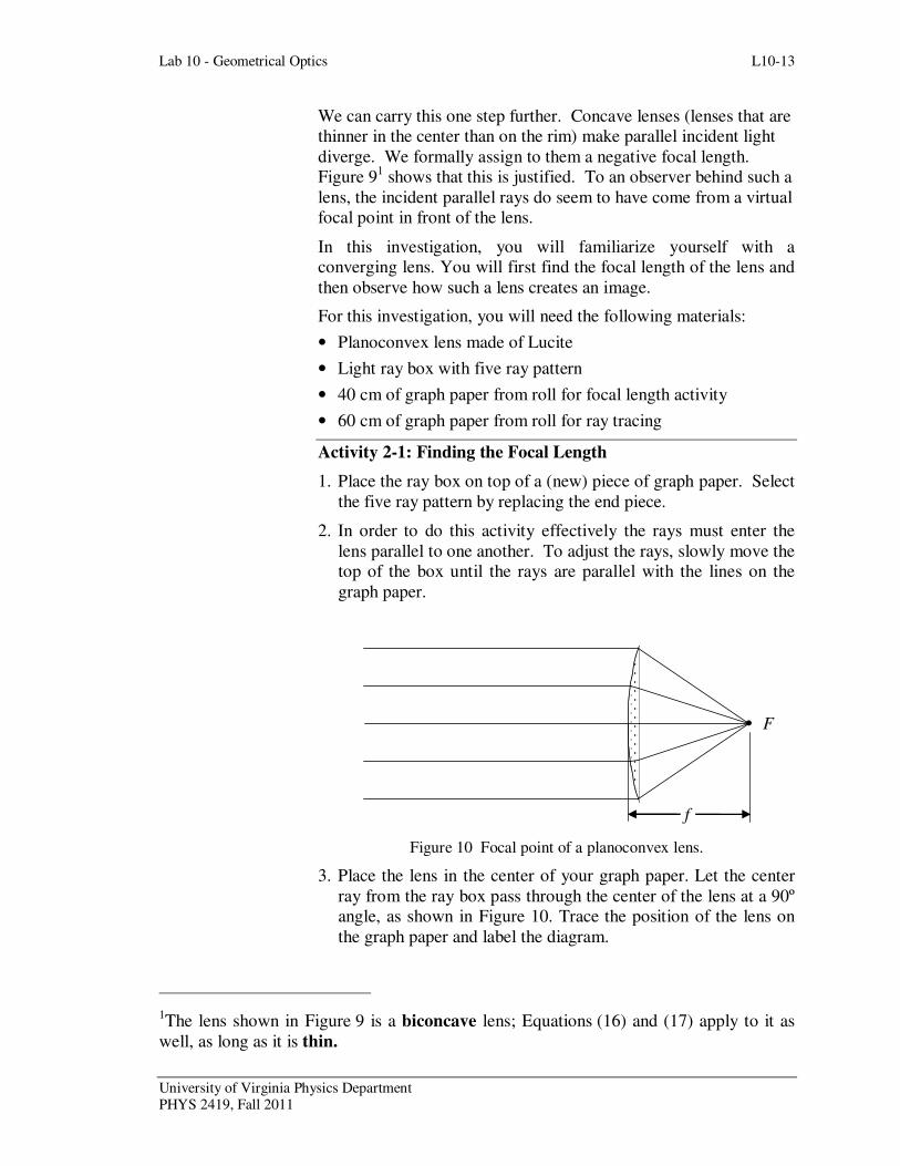
We can carry this one step further. Concave lenses (lenses that are
thinner in the center than on the rim) make parallel incident light
diverge. We formally assign to them a negative focal length.
Figure 91 shows that this is justified. To an observer behind such a
lens, the incident parallel rays do seem to have come from a virtual
focal point in front of the lens.
In this investigation, you will familiarize yourself with a
converging lens. You will first find the focal length of the lens and
then observe how such a lens creates an image.
For this investigation, you will need the following materials:
• Planoconvex lens made of Lucite
• Light ray box with five ray pattern
• 40 cm of graph paper from roll for focal length activity
• 60 cm of graph paper from roll for ray tracing
Activity 2-1: Finding the Focal Length
1. Place the ray box on top of a (new) piece of graph paper. Select
the five ray pattern by replacing the end piece.
2. In order to do this activity effectively the rays must enter the
lens parallel to one another. To adjust the rays, slowly move the
top of the box until the rays are parallel with the lines on the
graph paper.
F
f
Figure 10 Focal point of a planoconvex lens.
3. Place the lens in the center of your graph paper. Let the center
ray from the ray box pass through the center of the lens at a 90º
angle, as shown in Figure 10. Trace the position of the lens on
the graph paper and label the diagram.
1The lens shown in Figure 9 is a biconcave lens; Equations (16) and (17) apply to it as
well, as long as it is thin.

L10-14 Lab 10 - Geometrical Optics
University of Virginia Physics Department PHYS 2419, Fall 2011
4. Note that the rays converge at a point on the other side of the
lens. This is the focal point F for the lens. To measure it, make
points that will allow you to trace the rays entering and leaving
the lens.
5. Remove both the lens and the ray box to measure f.
f cm
Prediction 2-1: What will happen if you place the lens backwards
over the position in steps 3 and 4? What will happen to the focal
point F and focal length f ?
6. Turn the lens around and place it at the previous position to
determine if the orientation of the lens influences its focal
length.
Question 2-1: Do the lines converge at the same point as the value
that you found in step 4? Should light incident on either side
collect at the same point? What does this tell you about the lens?
Activity 2-2: Ray Tracing
This activity is designed to test the imaging properties of the lens.
A ray-tracing diagram like the one shown in Figure 7 will be
created.
1. Place a clean 60 cm long piece of graph paper on the table.
2. Align the planoconvex lens somewhere on the graph paper.
Allow about 25 cm clear on either side of the lens. Draw the
central axis (see Figure 7). Draw around the lens to mark its
position and mark the two focal points F on the central axis on
either side of the lens. Use the value you found in Activity 2-1.
3. To test how an image is formed, you will draw an object arrow
like that shown in Figure 7 on your piece of graph paper. Place

Lab 10 - Geometrical Optics L10-15
University of Virginia Physics Department PHYS 2419, Fall 2011
the tip of the arrow at a distance of 2f from the lens and about
1.5 cm from the central axis. Record your values.
Object Distance (o): __________
Object Size (O): __________
Prediction 2-1: Using the focal length f , object size O and object
distance o that you measured above, use the thin lens formulae
[Equations (16) and (17)] to calculate the theoretical values for the
image distance and size and the magnification. Insert your
calculated values in Table 2-1.
Table 2-1
Image
distance
(i)
Image size
(I)
Magnification
Theory
Experimental
4. Using a single ray from the ray box, mark on your paper the ray
paths on both sides of the lens the rays shown in Figure 7. Use
a different marking scheme (e.g., •, ×, o) for points along each
of the three rays. Mark two points on either side of the lens to
help you draw the rays later after you remove the lens. Your
three rays should be as follows:
• Ray 1 should go through F on its way to the image point
• Ray 2 should enter the lens parallel to the optical axis
• Ray 3 should pass through the lens nearly unbent
5. Note where the three rays seem to indicate the image should be.
You have found the image of only one point – the tip of the
object arrow, but that is enough to deduce the entire image.
Draw an arrow indicating where the image is. Measure the
image distance and image size and fill in the experimental
values in Table 2-1. Calculate the magnification and enter it
into Table 2-1. Include your labeled diagram with your group
report.

L10-16 Lab 10 - Geometrical Optics
University of Virginia Physics Department PHYS 2419, Fall 2011
Question 2-2: Discuss the agreement between your
experimental and theoretical values. [Do not be disappointed if
things do not work out exactly. Our “thin lens” is a bit on the
pudgy side.]
INVESTIGATION 3: IMAGE FORMATION BY CONVERGING LENSES
In order to examine the image formed by a converging lens, you
will need the following:
● Optical bench ● Lens holder
● 100 mm lens2 ● 200 mm lens
● Illuminated object ● Viewing screen
● Small see-through ruler ● 3 meter tape
● Small desk lamp
Activity 3-1: Image Formation by a Converging Lens
In this activity, you will see the relative positions for the object and
image distances formed by a converging lens.
Image
Lens
Object
Figure 11 Creation of an inverted real image on the optical bench.
2 Lenses are labeled by focal length, not by any geometrical parameters such as a radius
of curvature.
Lab 10 - Geometrical Optics L10-17
University of Virginia Physics Department PHYS 2419, Fall 2011
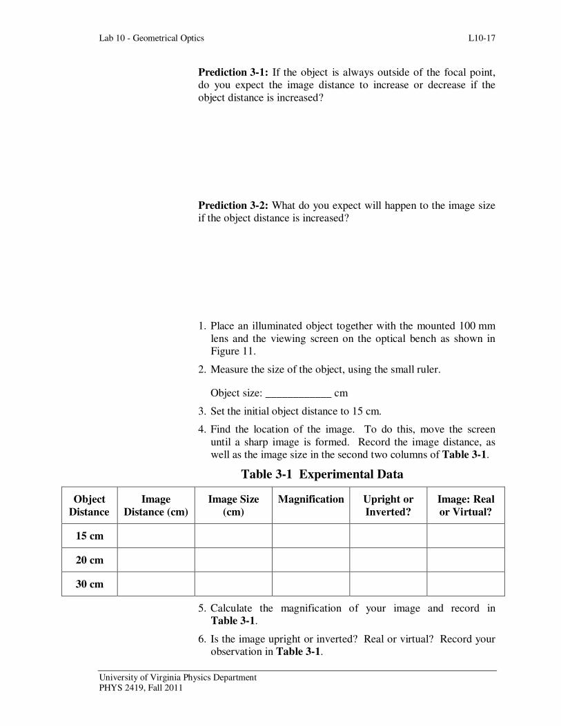
Prediction 3-1: If the object is always outside of the focal point,
do you expect the image distance to increase or decrease if the
object distance is increased?
Prediction 3-2: What do you expect will happen to the image size
if the object distance is increased?
1. Place an illuminated object together with the mounted 100 mm
lens and the viewing screen on the optical bench as shown in
Figure 11.
2. Measure the size of the object, using the small ruler.
Object size: ____________ cm
3. Set the initial object distance to 15 cm.
4. Find the location of the image. To do this, move the screen
until a sharp image is formed. Record the image distance, as
well as the image size in the second two columns of Table 3-1.
Table 3-1 Experimental Data
Object
Distance
Image
Distance (cm)
Image Size
(cm)
Magnification Upright or
Inverted?
Image: Real
or Virtual?
15 cm
20 cm
30 cm
5. Calculate the magnification of your image and record in
Table 3-1.
6. Is the image upright or inverted? Real or virtual? Record your
observation in Table 3-1.
L10-18 Lab 10 - Geometrical Optics
University of Virginia Physics Department PHYS 2419, Fall 2011
7. Try two other object distances, 20 cm and 30 cm. Record the
image distance, image size, magnification, orientation and
image properties of the image in Table 3-1.
Table 3-2 Theoretical Results
8. Use the thin lens formulae to calculate the image distance,
image size, and magnification for the three object distances
shown in Table 3-2. Let each lab partner calculate one. Enter
your calculated values into the table.
Question 3-1: How good is the agreement between your
experimental data in Table 3-1 and your calculations in Table 3-2?
Compare with your Predictions 3-1 and 3-2.
Prediction 3-3: All of the previous measurements involved an
object distance greater than the focal length. What will the image
look like if the object distance is less than the focal length?
9. Make sure that the object is oriented so it is facing the center of
the room and at the end of the optical bench furthest away from
the end of the table. This will make your upcoming
observations significantly easier.
10. Place the 10 cm lens so that the object distance is
approximately 5-8 cm.
Object distance Image distance
(cm)
Image size (cm) Magnification
15 cm
20 cm
30 cm

Lab 10 - Geometrical Optics L10-19
University of Virginia Physics Department PHYS 2419, Fall 2011
11. Stand at the end of the table so you are looking through the
lens at the object. Your distance to the lens should now be
approximately 1 m.
Question 3-2: Describe your image. Is it upright or inverted? If
you were to put a screen where you are looking, would an image
form there? What does this tell you about the image? Is it real or
virtual?
12. Now have one of the students in the group slowly move the
lens away from the object until it is approximately 10 cm from
the object. Make sure that another student is standing at the
end of the optical bench still looking through the lens.
Continue looking until the image disappears.
Question 3-3: Why is it that when the object is at the focal length
it produces no image? [Hint: consider the thin lens formulae.]
Activity 3-2: Test Fixed Distance
1. Position the lighted object 50 cm away from a viewing screen.
There will be two positions of the 100 mm lens where an image
will form. Let position “1” be where the lens is closest to the
object. [In your pre-lab you were asked find these distances
and to calculate the magnification for each position and these
results should be already entered into Table 3-3.]

L10-20 Lab 10 - Geometrical Optics
University of Virginia Physics Department PHYS 2419, Fall 2011
Table 3-3
Object
distance (cm)
Image
distance (cm)
Image size
(cm)
Magnification
Pre-lab 1
2
Experiment 1
2
2. Move the lens until you find the two positions that produce
sharp images. Measure and record (in Table 3-3) the image and
object distances and image size for each position.
3. Calculate the magnification for both positions and enter your
results into Table 3-3.
Question 3-4: Discuss the agreement between your predictions
and your experimental results.
Activity 3-3: Simulating a Camera
1. Place the object at one end of the optical bench and the viewing
screen at the other end.
2. Place the 100 mm lens near the viewing screen and move the
lens until you see a focused image on the screen. (On a real
camera, a focus knob will move the lens elements toward or
away from the film.) Note the size of the image.
3. Repeat with the 200 mm lens . Is the image larger?

Lab 10 - Geometrical Optics L10-21
University of Virginia Physics Department PHYS 2419, Fall 2011
Question 3-5: Based on these results, would you expect a
telephoto3 lens to be shorter, longer, or the same length as a
“normal” lens? Explain.
Activity 3-4: A Telescope
In this activity, you will see how converging lenses are used in the
formation of telescopes.
1. This setup should be somewhere in the lab. You do not need to
create it on your optical bench.
2. The 100 mm lens (the eyepiece or ocular) and the 200 mm lens
(the objective) should be approximately 30 cm apart on the
optical bench.
3. Look through the 100 mm lens (toward the 200 mm lens). You
can adjust the distance between the lenses until objects across
the room are in sharp focus.
Question 3-6: Describe the image you see. Is it upright or
inverted? Magnified?
3 A “telephoto” lens makes distant objects look larger.

L10-22 Lab 10 - Geometrical Optics
University of Virginia Physics Department PHYS 2419, Fall 2011
![2419 · 2021. 8. 10. · 2419. 2420. 2421. Deinition 5 [Comparability of two trends]. ... 2.2.4 ComparisonbetweenTrendsets. We extend Deinition 5 to the following observation over](https://static.fdocuments.us/doc/165x107/6149c57912c9616cbc68fa89/2021-8-10-2419-2420-2421-deinition-5-comparability-of-two-trends-.jpg)