Lab 1: System Overviews, Device ID-ing, Venting, Pump ...goeckner/plasma_tech_class/LABS/Lab 1 -...
11
Lab 1: System Overviews, Device ID-ing, Venting, Pump- down, Safety (Includes CR Gowning and procedures overview) CLEAN ROOM SAFETY There are many different types of sophisticated tools in the UTD Clean Room, which can have many lethal hazards. Some of these hazards may include Lethal Voltages, Gases, Acids, Solvents, Trip Hazards and Pinch Points. While in the Clean Room you should exercise caution, pay attention to detail and obey the clean room safety rules. If you observe unsafe acts or see unsafe conditions report them at once. CLEAN ROOM SAFETY RULES 1: NO RUNNING. 2: NO HORSE PLAY. 3: IF YOU ARE NOT FAMILIAR WITH IT DON’T DO IT. (ASK FOR TRAINING) 4: DO NOT TOUCH LIQIUDS AROUND MACHINES. 5: BE AWARE OF VOLTAGE SOURCES AND USE CAUTION AROUND THEM. 6: KEEP BODY PARTS AWAY FROM PINCH POINTS. 7: OBSERVE CHEMICAL SAFETY. 8: WATCH FOR TRIP HAZARDS. 9: EXIT CLEAN ROOM IMMEDIATELY IF ALARM SOUNDS. 10: WEAR APPROPRIATE PPE (PERSONAL PROTECTIVE EQUIPMENT) WHEN NEEDED. SAFETY IS EVERYONES RESPONSIBILITY!!!!!!
Transcript of Lab 1: System Overviews, Device ID-ing, Venting, Pump ...goeckner/plasma_tech_class/LABS/Lab 1 -...

Lab 1: System Overviews, Device ID-ing, Venting, Pump-down, Safety (Includes CR Gowning and procedures
overview)
CLEAN ROOM SAFETY
There are many different types of sophisticated tools in the UTD Clean Room,which can have many lethal hazards. Some of these hazards may include Lethal
Voltages, Gases, Acids, Solvents, Trip Hazards and Pinch Points. While in the CleanRoom you should exercise caution, pay attention to detail and obey the clean room
safety rules. If you observe unsafe acts or see unsafe conditions report them at once.
CLEAN ROOM SAFETY RULES
1: NO RUNNING.2: NO HORSE PLAY.3: IF YOU ARE NOT FAMILIAR WITH IT DON’T DO IT. (ASK FOR TRAINING)4: DO NOT TOUCH LIQIUDS AROUND MACHINES.5: BE AWARE OF VOLTAGE SOURCES AND USE CAUTION AROUND THEM.6: KEEP BODY PARTS AWAY FROM PINCH POINTS.7: OBSERVE CHEMICAL SAFETY.8: WATCH FOR TRIP HAZARDS.9: EXIT CLEAN ROOM IMMEDIATELY IF ALARM SOUNDS.10: WEAR APPROPRIATE PPE (PERSONAL PROTECTIVE EQUIPMENT) WHEN NEEDED.
SAFETY IS EVERYONES RESPONSIBILITY!!!!!!

CLEAN ROOM GOWNING PROCEDURE
In a clean room environment we try to protect the product (wafers, subtrate and microdevices) from particles. The human is a particle generator. For this reason we wearspecial clothing while in the clean room. The following is the proper sequence for cleanroom gowning for the UTD clean room.Outer Gowning Area:1: Place shoe covers over street shoes.Inner Gowning Area:2: Place hairnet or hood over hair. Make sure no hair is exposed.3: Put on smock or overall suit.4: Put on gloves.5: Wear appropriate eye protection.
When leaving clean room remove in reverse order.
CAPPY PUMPDOWN
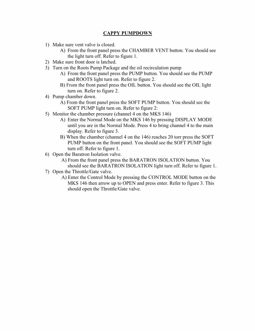
1) Make sure vent valve is closed.A) From the front panel press the CHAMBER VENT button. You should see
the light turn off. Refer to figure 1.2) Make sure front door is latched.3) Turn on the Roots Pump Package and the oil recirculation pump
A) From the front panel press the PUMP button. You should see the PUMPand ROOTS light turn on. Refer to figure 2.
B) From the front panel press the OIL button. You should see the OIL lightturn on. Refer to figure 2.
4) Pump chamber down. A) From the front panel press the SOFT PUMP button. You should see the
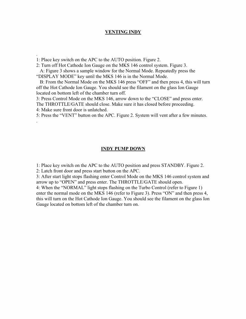
SOFT PUMP light turn on. Refer to figure 2:5) Monitor the chamber pressure (channel 4 on the MKS 146)
A) Enter the Normal Mode on the MKS 146 by pressing DISPLAY MODEuntil you are in the Normal Mode. Press 4 to bring channel 4 to the maindisplay. Refer to figure 3.
B) When the chamber (channel 4 on the 146) reaches 20 torr press the SOFTPUMP button on the front panel. You should see the SOFT PUMP lightturn off. Refer to figure 1.
6) Open the Baratron Isolation valve. A) From the front panel press the BARATRON ISOLATION button. You
should see the BARATRON ISOLATION light turn off. Refer to figure 1.7) Open the Throttle/Gate valve.
A) Enter the Control Mode by pressing the CONTROL MODE button on theMKS 146 then arrow up to OPEN and press enter. Refer to figure 3. Thisshould open the Throttle/Gate valve.
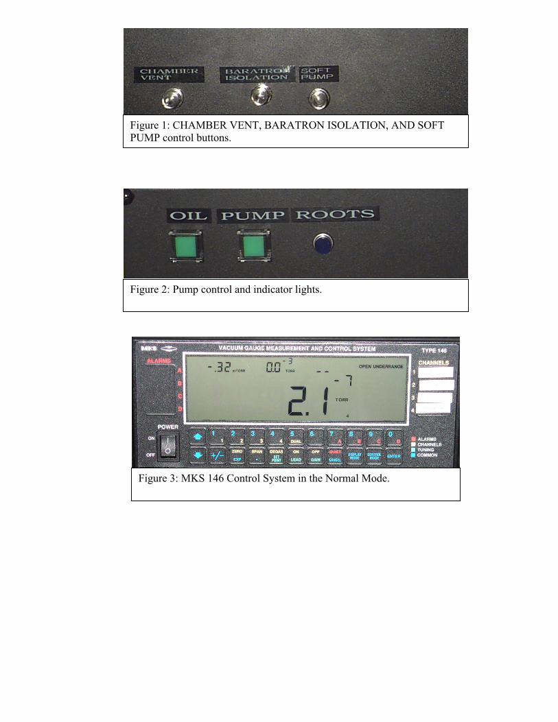
Figure 1: CHAMBER VENT, BARATRON ISOLATION, AND SOFTPUMP control buttons.
Figure 2: Pump control and indicator lights.
Figure 3: MKS 146 Control System in the Normal Mode.

VENTING CAPPY
1) Close the Barartron Isolation valve.A) From the front panel press the BARATRON ISOLATION button. You
should see the light turn off. Refer to figure 1.2) Unlatch front door.3) Close Throttle/Gate valve.
A) Enter the Control Mode by pressing the CONTROL MODE button on the MKS 146 then arrow down to CLOSE and press enter. Refer to figure 3.This should close the Throttle/Gate valve.
4) Vent the chamber.A) From the front panel press the CHAMBER VENT button. You should
see the light turn on. Refer to figure 1.B) When chamber has vented (front door will open) press the CHAMBER
VENT button. You should see the light turn off. Refer to figure 1.
If system is not going to be used pump chamber down by using the pump downprocedure and close the Throttle/Gate valve then turn off the Pump Package andOil recirculation pump by pressing the OIL button and then the PUMP button.You should see the OIL, PUMP, and ROOTS light turn off.

VENTING MAGGIE
1: Place key switch on the APC to the Auto position. Figure 12: Turn Ion Gauge off on the MKS 146 Control System. Figure 2. A: Figure 2 shows a sample window the Normal Mode. Repeatedly press the“DISPLAY MODE” key until the MKS is in the Normal Mode. B: From the Normal Mode on the MKS 146 press “OFF” and then press 4. You shouldsee the filament in the glass Ion Gauge located on top of the chamber turn off.3: Make sure the front door is unlatched.4: Press the Vent button on the APC. Figure 1. Chamber will come to atmosphericpressure after a few minutes.
PUMPING DOWN MAGGIE
1: Place key switch on the APC to the Auto position and press STANDBY. Figure 1.2: Latch front door and press Start on the APC.3: When the Start light stops flashing on the APC turn on the Ion Gauge on the MKS 146. A: From the Normal Mode on the MKS 146 press “ON” then press 4. Figure 2. Youshould see the filament in the glass Ion Gauge located on top of the chamber turn on.

Figure 1:Auto Pumpdown Control
Figure 2: MKS 146 CONTROLSYSTEM
VENTING INDY
.1: Place key switch on the APC to the AUTO position. Figure 2.2: Turn off Hot Cathode Ion Gauge on the MKS 146 control system. Figure 3. A: Figure 3 shows a sample window for the Normal Mode. Repeatedly press the“DISPLAY MODE” key until the MKS 146 is in the Normal Mode. B: From the Normal Mode on the MKS 146 press “OFF” and then press 4, this will turnoff the Hot Cathode Ion Gauge. You should see the filament on the glass Ion Gaugelocated on bottom left of the chamber turn off.3: Press Control Mode on the MKS 146, arrow down to the “CLOSE” and press enter.The THROTTLE/GATE should close. Make sure it has closed before proceeding.4: Make sure front door is unlatched.5: Press the “VENT” button on the APC. Figure 2. System will vent after a few minutes..
INDY PUMP DOWN
1: Place key switch on the APC to the AUTO position and press STANDBY. Figure 2.2: Latch front door and press start button on the APC.3: After start light stops flashing enter Control Mode on the MKS 146 control system andarrow up to “OPEN” and press enter. The THROTTLE/GATE should open.4: When the “NORMAL” light stops flashing on the Turbo Control (refer to Figure 1)enter the normal mode on the MKS 146 (refer to Figure 3). Press “ON” and then press 4,this will turn on the Hot Cathode Ion Gauge. You should see the filament on the glass IonGauge located on bottom left of the chamber turn on.

Figure 1: Turbo Control
Figure 2: Auto Pumpdown Control
Figure 3: MKS 146 Control System

VENTING HOLLY
*WARNING*The Hollow Cathode source is very sensitive to moisture. Only vent this chamberwhen absolutely necessary. After system is pumped down, outgas Hollow Cathodefor at least one hour.
1: Plug in Chamber Vent Pilot Valve on the Pilot Valve Manifold. Figure 1.2: Place key switch on the APC to the AUTO position. Figure 3.3: Turn off Cold Cathode Ion Gauge on the MKS 146 control system. A: Figure 4 shows a sample window for the Normal Mode. Repeatedly press the“DISPLAY MODE” key until the MKS 146 is in the Normal Mode. B: From the Normal Mode on the MKS 146 press “OFF” and then press 3.4: Press Control Mode on the MKS 146, arrow down to the “CLOSE” and press enter.The THROTTLE/GATE VALVE should close. Make sure it has closed beforeproceeding.5: Make sure front door is unlatched.6: Press the “VENT” button on the APC. Figure 3.7: When system is vented unplug the chamber vent on the pilot valve manifold. Figure 1.
HOLLY PUMP DOWN
1: Place key switch on the APC to the AUTO position and press STANDBY. Figure 3.2: Latch front door and press START button on the APC.3: After START light stops flashing enter Control Mode on the MKS 146 control systemand arrow up to “OPEN” and press enter. The THROTTLE/GATE should open.4: When the “NORMAL” light stops flashing on the Turbo Control (refer to Figure 2)enter the normal mode on the MKS 146 (refer to Figure 4). Press “ON” and then press 3,this will turn on the Cold Cathode Ion Gauge.

Figure 2: Turbo Control
Figure 3: Auto Pumpdown Control
Figure 4: MKS 146 Control System
Figure 1: Pilot Valve Manifold