Having a bad day??. ...nothing to do... Everything seems unreachable.

Lab 1: Router Programming Details Aim: To provide a foundation for the investigation of firewalls
Activities 1. In groups of three, select a router to program, and setup the network given in
Figure 1. Each person should program one of the routers. The complete network must run the same routing protocol (such as RIP).
S1:192.168.0.1/24
S0:192.168.0.2/24
E0:167.10.11.1/16E0:167.10.11.2/16
S0:172.20.30.1/24
S0:172.20.30.2/24
Router 1
Router 2 Router 3
FA0/1 FA0/2 FA0/3
R1: E0 R2: E0 R3: E0
Poss. Alt: S0 - S0/0S1 - S0/1E0 - FA0E0 - FA0/0
Poss. Alt: S0 - S0/0S1 - S0/1E0 - FA0E0 - FA0/0
Figure 1: Network configuration
2. Configure the devices as follows: Router 1: enable config t interface s0/0 ip address 172.20.30.1 255.255.255.0 no shutdown exit interface s0/1 ip address 192.168.0.1 255.255.255.0 no shutdown router rip network 172.20.30.0 network 192.168.0.0 exit line vty 0 4 password hello login
Author: W.Buchanan 1

Router 2: enable config t interface s0/0 ip address 172.20.30.2 255.255.255.0 clock rate 56000 no shutdown exit interface fa0/0 ip address 167.10.11.2 255.255.0.0 no shutdown router rip network 172.20.30.0 network 167.10.0.0 exit line vty 0 4 password hello login
Router 3: enable config t interface s0/0 ip address 192.168.0.2 255.255.255.0 clock rate 56000 no shutdown exit interface fa0/0 ip address 167.10.11.1 255.255.0.0 no shutdown router rip network 192.168.0.0 network 167.10.0.0 exit line vty 0 4 password hello login
2. Once programmed, conduct the following: A. Ping your own ports. Are they responding? Yes/No If not, check your configuration. B. Ping the neighbouring ports. Are they responding? Yes/No
If not, check your configuration, and your neighbours. C. Telnet into each of the neighbouring routers, one at a time? Is it successful? Yes/No
Author: W.Buchanan 2

Lab 2: ACL Programming Verification (TELNET) Details Aim: To verify the operation of an ACL.
Activities 1. In groups of three, select a router to program, and setup the network given in
Figure 2. Each person should program one of the routers. The complete network must run the same routing protocol (such as RIP). In this case, we wish to block TELNET access from Router 1 to Router 2.
Router 1
Router 2 Router 3
Ethernetlink
Seriallink
E0:176.16.0.2/24 E0:176.16.0.1/24
S0:192.168.02/24
S1:192.168.0.1/24
Figure 2: Network configuration
2. Next configure the devices with the following configuration: Router 3: hostname "Router3" ! interface FastEthernet0/0 ip address 176.16.0.1 255.255.255.0 ip access-group 100 in duplex auto speed auto interface Serial0/0 ip address 192.168.0.2 255.255.255.0 ip access-group 101 in clockrate 56000 ! interface Serial0/1 no ip address shutdown ! router rip network 176.16.0.0
Author: W.Buchanan 3

network 192.168.0.0 ! access-list 101 deny tcp 192.168.0.0 0.0.0.255 176.16.0.0 0.0.0.255 eq telnet access-list 101 permit ip any any ! line con 0 line aux 0 line vty 0 4 password fred login end Router 2: hostname "Router2" ! interface FastEthernet0/0 ip address 176.16.0.2 255.255.255.0 ! interface Serial0/0 no ip address shutdown ! router rip network 176.16.0.0 ! line con 0 line aux 0 line vty 0 4 password fred login Router 1: hostname "Router1" ! interface FastEthernet0/0 no ip address shutdown ! interface Serial0/1 ip address 192.168.0.1 255.255.255.0 ! interface Serial0/2 no ip address shutdown ! router rip network 192.168.0.0 ! line con 0 line aux 0 line vty 0 4 password fred login 3. Once programmed, conduct the following:
Author: W.Buchanan 4

A. Ping your own ports. Are they responding? Yes/No If not, check your configuration. B. Ping the neighbouring ports. Are they responding? Yes/No
If not, check your configuration, and your neighbours. 3. Telnet from Router 2 to Router 1. Is it possible? Yes/No 4. Telnet from Router 1 to Router 2. Is it possible? Yes/No Notes:
Author: W.Buchanan 5

Lab 3: ACL Programming Exercise (TELNET) Details Aim: Implementation of firewalls using ACL’s
Activities 1. In groups of three, select a router to program, and setup the network given in
Figure 3. Each person should program one of the routers. The complete network must run the same routing protocol (such as RIP).
E0:167.10.11.1/16E0:167.10.11.2/16
S0:172.20.30.1/24
S0:172.20.30.2/24
Router 1
Router 2 Router 3
FA0/1 FA0/2 FA0/3
R1: E0 R2: E0 R3: E0
Poss. Alt: S0 - S0/0S1 - S0/1E0 - FA0E0 - FA0/0
Poss. Alt: S0 - S0/0S1 - S0/1E0 - FA0E0 - FA0/0
Figure 3: Network configuration
2. Once programmed, conduct the following: A. Ping your own ports. Are they responding? Yes/No If not, check your configuration. B. Ping the neighbouring ports. Are they responding? Yes/No
If not, check your configuration, and your neighbours. C. Telnet into each of the neighbouring routers, one at a time? Is it successful? Yes/No 3. Implement a firewall on Router 2, so that Router 1 cannot access Router 3 (using a standard ACL). D. Test by trying to TELNET from Router 3 to Router 1?
Is it successful? Yes/No E. Test by trying to TELNET from Router 1 to Router 3?
Is it unsuccessful? Yes/No
Author: W.Buchanan 6

4. Remove the ACL on Router 2, so that Router 1 can now communicate with Router 3.
F. Test by trying to TELNET from Router 3 to Router 1? Is it successful? Yes/No G. Test by trying to TELNET from Router 1 to Router 3?
Is it successful? Yes/No
5. Implement a firewall, using an extended ACL, on Router 2 so that it blocks an incoming any TELNET request from Router 3 (167.10.11.2), but still allows a TELNET request from Router 1 to Router 3.
H. Test by trying to TELNET from Router 3 to Router 1?
Is it unsuccessful? Yes/No I. Test by trying to TELNET from Router 1 to Router 3?
Is it successful? Yes/No 6. Change the IP address of E0 on Router 3 to 192.168.0.3. J. Test by trying to TELNET from Router 3 to Router 1?
Is it now successful? Yes/No K. Test by trying to TELNET from Router 1 to Router 3?
Is it successful? Yes/No 7. Change the ACL on Router 2 so that it now bars all addresses from 167.10.11.1 to
167.10.11.254 from TELNET’ing into Router 1. L. Test by trying to TELNET from Router 3 to Router 1?
Is it unsuccessful? Yes/No M. Test by trying to TELNET from Router 1 to Router 3?
Is it successful? Yes/No
Author: W.Buchanan 7

Lab 4: ACL Programming Verification (WWW) Details Aim: To verify the operation of an ACL.
Activities 1. In groups of three, select a router to program, and setup the network given in
Figure 4. Each person should program one of the routers. The complete network must run the same routing protocol (such as RIP). In this example, we wish to block WWW for an host with an address of 172.16.0.x access to a WWW server on Router 1.
Router 1
Router 2 Router 3
Ethernetlink
Seriallink
E0:176.16.0.2/24 E0:176.16.0.1/24
S0:192.168.02/24
S1:192.168.0.1/24
Figure 4: Network configuration
2. Next configure the devices with the following configuration: Router 3: hostname "Router3" ! interface FastEthernet0/0 ip address 176.16.0.1 255.255.255.0 ip access-group 102 in duplex auto speed auto interface Serial0/0 ip address 192.168.0.2 255.255.255.0 clockrate 56000 ! interface Serial0/1 no ip address shutdown ! router rip network 176.16.0.0
Author: W.Buchanan 8

network 192.168.0.0 ! access-list 102 deny tcp 176.16.0.0 0.0.0.255 192.168.0.0 0.0.0.255 eq www access-list 102 permit ip any any ! line con 0 line aux 0 line vty 0 4 password fred login ! end Router 2: hostname "Router2" ! interface FastEthernet0/0 ip address 176.16.0.2 255.255.255.0 ! interface Serial0/0 no ip address shutdown ! ip http server ! router rip network 176.16.0.0 ! line con 0 line aux 0 line vty 0 4 password fred login Router 1: hostname "Router1" ! interface FastEthernet0/0 no ip address shutdown ! interface Serial0/1 ip address 192.168.0.1 255.255.255.0 ! interface Serial0/2 no ip address shutdown ! ip http server ! router rip network 192.168.0.0 ! line con 0 line aux 0 line vty 0 4
Author: W.Buchanan 9

password fred login The ip http server command is used to setup a WWW server on the router. 3. Once programmed, conduct the following: From Router 1 telnet into the WWW port of Router 2, with: Router1#telnet 176.16.0.2 www Trying 176.16.0.2, 80 ... Open get index.html Content-type: text/html 4. The return should then be: content-type: text/HTTP/1.0 400 Bad Request Date: Mon, 01 Mar 1993 02:53:11 UTC Content-type: text/html Expires: Thu, 16 Feb 1989 00:00:00 GMT <H1>400 Bad Request</H1> 5. This shows that the WWW server is respond back with a WWW page. From Router 2 telnet into the WWW port of Router 1, with: Router2#telnet 192.168.0.1 www Trying 192.168.0.1, 80 ... % Destination unreachable; gateway or host down Next check that you can still access the WWW server from Router 1 to Router 2, such as: Router1#telnet 176.16.0.2 www Trying 176.16.0.2, 80 ... Open
Author: W.Buchanan 10

Lab 5: Blocking WWW (Exercise) Details Aim: Implementation of firewalls using ACL’s
Activities 1. In groups of three, select a router to program, and setup the network given in
Figure 5. Each person should program one of the routers. The complete network must run the same routing protocol (such as RIP). In this example apply an ACL on Router 2 which blocks WWW access from Router 1 to Router 3.
E0:167.10.11.1/16E0:167.10.11.2/16
S0:172.20.30.1/24
S0:172.20.30.2/24
Router 1
Router 2 Router 3
FA0/1 FA0/2 FA0/3
R1: E0 R2: E0 R3: E0
Poss. Alt: S0 - S0/0S1 - S0/1E0 - FA0E0 - FA0/0
Poss. Alt: S0 - S0/0S1 - S0/1E0 - FA0E0 - FA0/0
Figure 5: Network configuration
To test the system, verify the following: 1. That Router 3 can access the WWW server on Router 1. 2. That Router 1 cannot access the WWW server on Router 3.
Notes:
Author: W.Buchanan 11

Lab 6: Blocking Verification (ICMP)
Details Aim: To provide a guided example of blocking ICMP access for a given host
Activities 1. In groups of three, select a router to program, and setup the network given in
Figure 4. Each person should program one of the routers. The complete network must run the same routing protocol (such as RIP). In this example the network in Figure 7 will be configured, and an ICMP ping block will be applied from the 176.16.0.0 network to the host port of 192.168.0.1 on Router 3:
Router 1
Router 2 Router 3
Ethernetlink
Seriallink
E0:176.16.0.2/24 E0:176.16.0.1/24
S0:192.168.0.2/24
S1:192.168.0.1/24
Figure 6: Network configuration
2. Next setup the devices with the following configuration: Router 3: hostname "Router3" interface FastEthernet0/0 ip address 176.16.0.1 2 ip access-group 100 in
55.255.255.0
! interface Serial0/0 ip address 192.168.0.2 255.255.255.0 clockrate 56000 ! router rip network 176.16.0.0 network 192.168.0.0 ! ip classless ip http server ! access-list 100 deny icmp 176.16.0.0 0.0.0.255 host 192.168.0.1 echo access-list 100 permit ip any any
Author: W.Buchanan 12

Router 2: hostname "Router2" ! interface FastEthernet0/0 ip address 176.16.0.2 255.255.255.0 ip access-group 100 in ! interface Serial0/0 no ip address shutdown ! router rip network 176.16.0.0 Router 1: hostname "Router1" ! interface FastEthernet0/0 no ip address shutdown ! interface Serial0/1 ip address 192.168.0.1 255.255.255.0 ! interface Serial0/2 no ip address shutdown ! router rip network 192.168.0.0 2. Once programmed, conduct the following: A. Ping all the local ports on the routers. Are they responding? If not, check your configuration. Yes/No B. Ping from Router 2 to Router 1. Is the ping blocked? Yes/No If not, check your configuration. C. Ping from Router 1 to Router 2. Is the ping allowed? Yes/No If not, check your configuration. D. Perform the following, and investigate what effect it has on the ping process: no access-list 100 deny icmp 176.16.0.0 0.0.0.255 host 192.168.0.1 echo no access-list 100 permit ip any any access-list 100 deny icmp 176.16.0.0 0.0.0.255 host 192.168.0.1 access-list 100 permit ip any any E. Reapply the original ACL. Can router 2 ping 192.168.0.2? Yes/No
Author: W.Buchanan 13

E. Modify the ACL so that Router 2 cannot ping and computer on the 192.168.0.0 subnet. F. Modify the ACL so that Router 2 cannot ping the hosts from 192.168.0.1 to 192.168.0.7. Check the result by changing the port on Router 1 to 192.168.0.8. Notes:
Author: W.Buchanan 14

Lab 7: ACL Programming (ICMP blocking)
Details Aim: Implementation of firewalls using ACL’s
Activities 1. In groups of three, select a router to program, and setup the network given in
Figure 7. Each person should program one of the routers. The complete network must run the same routing protocol (such as RIP). In this example, block all pings from the 172.20.30.0 network to the 167.10.11.0 network.
E0:167.10.11.1/16E0:167.10.11.2/16
S0:172.20.30.1/24
S0:172.20.30.2/24
Router 1
Router 2 Router 3
FA0/1 FA0/2 FA0/3
R1: E0 R2: E0 R3: E0
Poss. Alt: S0 - S0/0S1 - S0/1E0 - FA0E0 - FA0/0
Poss. Alt: S0 - S0/0S1 - S0/1E0 - FA0E0 - FA0/0
Figure 7: Network configuration
To test the system, verify the following: A. Verify that Router 3 can ping every port on the network. B. Verify that Router 1 can ping the nodes on the 172.20.30.0 network, but cannot ping either 167.10.11.2 or 167.10.11.1.
Author: W.Buchanan 15

Lab 8: Verifying NAT Details Aim: Verifying NAT on a router
Activities 1. In groups of three, select a router to program, and setup the network given in
Figure 7. Each person should program one of the routers. The complete network must run the same routing protocol (such as RIP). NAT allows addresses inside a network to be mapped onto external addresses. In Figure 8 the inside network has addresses which attach to the 10.0.0.0 network. Then Router 3 maps these addresses to global addresses, from 192.168.16.10-254. Thus a device on the outside network will receive incoming requests from a host range from 192.168.16.10-254, and reply back to this device.
Router 1
Router 2
Router 3FA0/0: 10.0.0.2/24 FA0/0:10.0.0.2/24
S0/0:172.16.0.2/24
S0/1:172.16.0.1/24
InsidePool:192.168.16.10-192.168.16.254
Figure 8: Network configuration
The configuration commands for Router 1 is (where the default route is set to the connected Router 3 port): config t hostname Router1 interface s0/1 ip address 172.16.0.1 255.255.255.0 no shut exit ip route 0.0.0.0 0.0.0.0 172.16.0.2 end The configuration commands for Router 2 is (where the default route is set to the connected Router 3 port):
Author: W.Buchanan 16

config t hostname Router2 interface fa0/0 ip address 10.0.0.1 255.255.255.0 no shut exit ip route 0.0.0.0 0.0.0.0 10.0.0.2 end The configuration commands for Router 3 is: config t hostname Router3 interface fa0/0 ip address 10.0.0.2 255.255.255.0 no shut ip nat inside exit interface s0/0 ip address 172.16.0.2 255.255.255.0 ip nat outside clockrate 56000 no shut exit ip nat pool MyPool 192.168.16.10 192.168.16.254 netmask 255.255.255.0 ip nat inside source list 1 pool MyPool access-list 1 permit 10.0.0.0 0.0.0.255 end A. First go to Router 3 and have a look at the NAT mapping: Pro Inside global Inside local Outside local Outside global --- 192.168.16.10 10.0.0.1 --- --- B Thus it can be seen that the port 10.0.0.1 (which is on Router 2), has been
mapped statically to 192.168.16.11. Thus go to Router 1, and conduct the following:
Ping 10.0.0.1 Is it possible to ping the port? Ping 192.168.16.10 Is it possible to ping the port? C Thus it can be seen that the port 10.0.0.1 (which is on Router 2), has been
mapped statically to 192.168.16.11. Thus go to Router 2, and conduct the following:
Ping 172.16.0.1 Is it possible to ping the port?
Author: W.Buchanan 17

D To debug the NAT operations, run the command: debug ip nat E Repeat operation in B and C, and show that the result from the debug is in the form of: 00:42:53: NAT*: s=172.16.0.1, d=192.168.16.10->10.0.0.1 [59] 00:42:53: NAT*: s=10.0.0.1->192.168.16.10, d=172.16.0.1 [59] 01:05:01: NAT: s=10.0.0.1->192.168.16.10, d=172.16.0.1 [135] 01:05:01: NAT*: s=172.16.0.1, d=192.168.16.10->10.0.0.1 [135] F Explain the result of this. Which one of the traces is from Router 1 to Router 2, and which one is from Router 2 to Router 1?
Author: W.Buchanan 18

Lab 9: Designing NAT Details Aim: Implementation of NAT on a router
Activities Implement a NAT design to complete the following (Figure 9): Inside network: 176.16.0.0 Outside network: 192.168.0.0 NAT pool: 10.0.1.1 - 10.0.1.100
Router 1
Router 2 Router 3
Seriallink
E0:176.16.0.2/24 E0:176.16.0.1/24
S0:192.168.0.2/24
S1:192.168.0.1/24
NAT pool:10.0.1.1-10.0.1.100
Figure 9: Network configuration
To test the system, verify the following: 1. That Router 2 can ping Router 1. 2. That Router 2 uses the Pool addresses to access Router 2. 3. That Router 2 cannot be contacted using its private address.
Author: W.Buchanan 19

Lab 10: Basic PIX Configuration Details Aim: Verifying the PIX pod
Activities In this you can use the emulator at http://www.buchananweb.co.uk/pix.html 1. You should start in the user mode: > 2. Go into the EXEC mode using the enable command. > enable
How does the prompt change?
3. From the EXEC mode go into the Global Configuration Mode, and use the
hostname command to change the hostname to MyPIX. # ? # config t (config)# hostname MyPIX (config)# password cisco (config)# enable password cisco
How does the prompt change?
4. Exit from the Global Configuration Mode using exit, and list the current running-
config with show running-config. (config) # exit # show running-conf
Outline some of the settings in the running-config:
Author: W.Buchanan 20

5. Complete the following commands ? #
# show ? # show nameif # show version # show interface # show processes # show conn # show fixup # show aaa # show aaa-server # show blocks # show domain-name # show history # show traffic # show memory # show clock # show terminal # show timeout # show ua
Using the information from above what are the following: How much memory does it have? What is version of the PIX firewall software? What is the version of the BIOS? Which ports does the PIX device have?
6. The IP addresses that are set can be shown at any time with: # show ip 7. The show route commands shows the routes that have been setup. It will add a
static route for every port that has been created. In this case there is only one port which has a default IP address (the inside port which has an IP address of 10.0.0.1 and a subnet mask of 255.255.255.0):
# show route 8. It should be seen that this gives: inside 10.0.0.0 255.255.255.0 10.0.0.1 CONNECT static 9. Program the three ports of the PIX with: # nameif # config t (config)# ?
Author: W.Buchanan 21

(config)# ip ? (config)# ip address inside 192.168.1.1 255.255.255.0 (config)# ip address outside 10.1.1.1 255.255.0.0 (config)# ip address inf2 192.168.2.1 255.255.0.0 (config)# exit # show ip # show running
Ping the newly defined ports. Are they responding?
10. Program the three ports of the PIX with: # nameif # config t (config)# ? (config)# interface ? (config)# interface e0 auto (config)# interface e1 auto (config)# interface e2 auto (config)# exit # show running
Ping the newly defined ports. Are they responding?
11. Set the domain-name with: # config t (config)# domain-name fred.com (config)# exit # show running 12. To set the time-outs: # config t (config)# telnet timeout 10 (config)# ssh timeout 10 (config)# console timeout 5 (config)# exit # show running 13. To enable a WWW server: # config t (config)# http server enable (config)# exit # show running 14. To disable the WWW server: # show http # config t
Author: W.Buchanan 22

(config)# no http server enable (config)# exit # show running 15. To enable a user: # config t (config)# username fred password fred (config)# exit # show running 16. To enable banners: # config t (config)# banner motd # hello # (config)# banner exec # welcome to exec # (config)# banner login # welcome to PIX # # show running 17. To disable banners: # config t (config)# no banner motd (config)# no banner exec (config)# no banner login # show running 18. To change the IF name of a port: # nameif # config t (config)# nameif e2 dmz security40 (config)# exit # nameif # show running 19. A static route is setup for each of the IP addresses that have been setup. For
example: # config t (config)# ip address inside 192.168.1.1 255.255.255.0 (config)# ip address outside 10.1.1.1 255.255.0.0 (config)# ip address inf2 192.168.2.1 255.255.0.0 (config)# exit (config)# show route gives: inside 192.168.1.0 255.255.255.0 192.168.1.1 1 CONNECT static outside 10.1.0.0 255.255.0.0 10.1.1.1 1 CONNECT static inf2 192.168.0.0 255.255.0.0 192.168.2.1 1 CONNECT static 20. To add a route: # config t
Author: W.Buchanan 23

(config)# route inside 10.1.1.0 255.255.255.0 10.0.0.3 # show running The additional line in the running configuration is: route inside 192.1.1.0 255.255.255.0 192.1.1.3 1 21. To show all the routes: # show route inside 192.1.1.0 255.255.255.0 192.1.1.3 1 OTHER static inside 192.168.1.0 255.255.255.0 192.168.1.1 1 CONNECT static outside 10.1.0.0 255.255.0.0 10.1.1.1 1 CONNECT static inf2 192.168.0.0 255.255.0.0 192.168.2.1 1 CONNECT static 22. To get rid of a route: # config t (config)# no route inside 10.1.1.0 255.255.255.0 10.0.0.3 # show running 23. For dynamic routing, the RIP command can be used: # config t (config)# rip ? (config)# rip outside passive version 2 authentication md5 HKEY abc (config)# exit # show running The PIX device accepts RIP version 2, which supports MD5 authentication. In this case the key is set to “abc”. 24. To set the IP address of the NTP server: # config t (config)# ntp ? (config)# ntp server 10.0.0.30 # show running 25. To get rid of access to the NTP server: # config t (config)# ntp ? (config)# no ntp server 10.0.0.30 # show running 26. To configure the protocols that are enabled or disabled on the PIX firewall: # show fixup # config t (config)# fixup ?
Author: W.Buchanan 24

27. To disable the FTP protocol on the PIX device, then: (config)# no fixup protocol ftp 23 (config)# exit # show fixup 28. To enable it: (config)# fixup protocol ftp 23 (config)# exit # show fixup 29. To change the port that the PIX device listens for HTTP traffic: (config)# fixup protocol http 8080 (config)# exit # show fixup 30. To show CPU usage: # show cpu use 31. To show the details of the EEPROM: # show eeprom 32. To show details of aaa-server: # show aaa-server 33. To show the details of the NAT and global commands: # config t (config)# nat ? (config)# global ? 34. To setup NAT on the inside interface to use the network addresses from 10.0.0.1 to
10.0.0.254: (config)# nat (inside) 1 10.0.0.0 255.255.255.0 (config)# exit # show running 35. Next we could setup NAT in the DMZ so that it uses addresses from 172.16.0.1 to
172.16.0.254: (config)# nameif e2 dmz security50 (config)# nat (dmz) 1 172.16.0.0 255.255.255.0 (config)# exit # show nat # show running
Author: W.Buchanan 25

36. Finally we can assign the addresses on the outside and within the DMZ to be globally available addresses:
# config t (config)# global (outside) 1 192.168.0.20-192.168.0.254 netmask 255.255.255.0 (config)# global (dmz) 1 172.16.0.0-172.16.0.254 netmask 255.255.255.0 (config)# exit # show global # show running The global command assigns a public address to internal hosts which are available
through the firewall. 37. To show the details of the ICMP command, and to deny a ping response from the
PIX from devices outside our network: # config t (config)# icmp ? (config)# icmp deny any echo outside 38. To show the details of the DHCP command: # config t (config)# dhcpd ? (config)# dhcpd address 192.168.0.20-192.168.0.40 inside (config)# exit # show dhcpd # show running which operates a DHCP daemon on the inside network. To add a DNS link: 39. To show the details of the DHCP command: # config t (config)# dhcpd dns 192.168.0.100 # show running
Example configuration 1: ACLs The following is a configuration which blocks WWW access from inside the network, and permits access to a WWW server in the DMZ (Figure 10). > enable # config t (config)# nameif ? (config)# nameif e2 dmz security50 (config)# ip address inside 10.0.0.1 255.255.255.0 (config)# ip address outside 192.168.0.1 255.255.255.0 (config)# ip address dmz 172.16.0.1 255.255.255.0 (config)# interface e0 auto (config)# interface e1 auto (config)# interface e2 auto (config)# access-list ?
Author: W.Buchanan 26

(config)# access-list acl_out1 permit tcp 10.0.0.0 255.0.0.0 host 172.16.0.2 eq www
(config)# access-list acl_out1 deny tcp any any eq www (config)# access-list acl_out1 permit ip any any (config)# access-group ? (config)# access-group acl_out1 in interface inside (config)# exit # show running To allow ICMP: access-list acl_out1 permit icmp any any
E0 – outside(192.168.0.2/24)
E2 – DMZ(172.16.0.1/24)
E1 – inside(10.0.0.1/16)
Perimeterrouter
PIX
WWW Server(172.16.0.2/24)
(10.0.0.2)
(192.168.0.1/24)
Figure 10: PIX firewall
Example configuration 2: NAT The following is a configuration which allows NAT to be setup on the inside and DMZ networks, and assigns global addresses to the DMZ and to the outside network. > enable # config t (config)# nameif ? (config)# nameif e2 dmz security50 (config)# ip address inside 10.0.0.1 255.255.255.0 (config)# ip address outside 192.168.0.1 255.255.255.0 (config)# ip address dmz 172.16.0.1 255.255.255.0 (config)# nat (inside) 1 10.0.0.0 255.255.255.0 (config)# nat (dmz) 1 172.16.0.0 255.255.255.0 (config)# global (outside) 1 192.168.0.20-192.168.0.254 netmask 255.255.255.0 (config)# global (dmz) 1 172.16.0.2-172.16.0.254 netmask 255.255.255.0 (config)# interface e0 auto (config)# interface e1 auto (config)# interface e2 auto
Author: W.Buchanan 27

(config)# exit # show running
E0 – outside(192.168.0.2/24)
E2 – DMZ(172.16.0.1/24)
E1 – inside(10.0.0.1/16)
Perimeterrouter
PIX
WWW Server(172.16.0.2/24)
(10.0.0.2)
(192.168.0.1/24)
Global pool192.168.0.20-192.168.0.254
Figure 11: PIX firewall
Author: W.Buchanan 28

Lab 11: Verifying PIX Details Aim: Verifying the PIX pod
Activities 1. In groups of three, select a router to program, and setup the network given in
Figure 12. Each person should program one of the routers/PIX.
Router 2
Router 1
PIX
e0 [172.16.0.1/24]
e1 [10.0.0.1/16]
e2 [192.168.1.1]
e0 [172.16.0.2/24]
e0 [10.0.0.2/16]
Host
inside
outside
Figure 12: PIX pod example
The outline configuration of Router 2 is (146.176.165.230:2016): enable config t hostname outsideR int e0 ip address 172.16.0.2 255.255.255.0 no shut exit router rip network 172.16.0.0 exit ip route 0.0.0.0 0.0.0.0 172.16.0.1 line vty 0 4 password fred login exit
The outline configuration of Router 1 is (146.176.165.230:2015):
Author: W.Buchanan 29

enable config t hostname insideR int e0 ip address 10.0.0.2 255.255.0.0 no shut exit router rip network 10.0.0.0 exit ip route 0.0.0.0 0.0.0.0 10.0.0.1 line vty 0 4 password fred login exit
and the PIX is (146.176.165.230:2014): enable config t hostname myPIX interface ethernet0 auto interface ethernet1 auto interface ethernet2 auto nameif ethernet0 outside security0 nameif ethernet1 inside security100 nameif ethernet2 dmz security50 hostname pixfirewall ip address outside 172.16.0.1 255.255.255.0 ip address inside 10.0.0.1 255.255.0.0 ip address dmz 192.168.1.1 255.255.255.0 global (outside) 1 192.168.2.20-192.168.2.254 nat (inside) 1 10.0.0.0 255.255.0.0 0 0 route outside 0.0.0.0 0.0.0.0 172.16.0.2 1
2. Next verify the NAT translation by using the following command on the PIX device: pixfirewall# show xlate 1 in use, 1 most used Global 192.168.2.20 Local 10.0.0.2 3. Now go to Router 1 (the inside router), and telnet from there to Router 2: insideR#telnet 172.16.0.2 Trying 172.16.0.2 ... Open User Access Verification Password: outsideR> 4. Next go to Router 2 (the outside router), and try and telnet into Router 1: outsideR#telnet 10.0.0.2 Trying 10.0.0.2 ... Which shows that the traffic from inside to outside is allowed, but outside to inside is barred.
Author: W.Buchanan 30

5. Now enable the WWW server on Router 2: outsideR#config t Enter configuration commands, one per line. End with CNTL/Z. outsideR(config)#ip http server outsideR(config)#exit 6. Next, to prove that traffic from inside the network can access the outside
network, go to Router 1 (inside), and access the WWW server on Router 2: insideR#telnet 172.16.0.2 www Trying 172.16.0.2, 80 ... Open get index.html content-type: http/html HTTP/1.0 400 Bad Request Date: Sun, 07 Mar 1993 13:58:59 UTC Content-type: text/html Expires: Thu, 16 Feb 1989 00:00:00 GMT <H1>400 Bad Request</H1> 7. Now, locate the host which is on the DMZ connection, and determine its IP
address, such as: pixfirewall# ping 192.168.1.200 192.168.1.200 NO response received -- 1000ms 192.168.1.200 NO response received -- 1000ms 192.168.1.200 NO response received -- 1000ms pixfirewall# ping 192.168.1.201 192.168.1.201 NO response received -- 1000ms 192.168.1.201 NO response received -- 1000ms 192.168.1.201 NO response received -- 1000ms pixfirewall# ping 192.168.1.202 192.168.1.202 NO response received -- 1000ms 192.168.1.202 NO response received -- 1000ms 192.168.1.202 NO response received -- 1000ms pixfirewall# ping 192.168.1.203 192.168.1.203 response received -- 0ms 192.168.1.203 response received -- 0ms 192.168.1.203 response received -- 0ms 8. Now, and this is not advisable from a security point-of-view, we shall allow
everything from outside to access the inside network: pixfirewall# config t pixfirewall(config)# access-list a2 permit ip any any pixfirewall(config)# access-group a2 in interface outside pixfirewall(config)# exit 9. Now go back to Router 2 (inside) and try and telnet, and now it should be
possible to telnet into Router 1: outsideR#telnet 10.0.0.2
Author: W.Buchanan 31

Trying 10.0.0.2 ... outsideR#telnet 192.168.2.20 Trying 192.168.2.20 ... Open User Access Verification Password: 10. Explain why Router 2 is accessible using 192.168.2.20? 11. Using the show route command, show the routes, and identify the static route,
such as: outside 0.0.0.0 0.0.0.0 172.16.0.2 1 OTHER static inside 10.0.0.0 255.255.0.0 10.0.0.2 1 CONNECT static outside 172.16.0.0 255.255.255.0 172.16.0.1 1 CONNECT static dmz 192.168.1.0 255.255.255.0 192.168.1.1 1 CONNECT static 12. Finally erase the configuration on the PIX: pixfirewall# write erase Erase PIX configuration in flash memory? [confirm] pixfirewall# reload Proceed with reload? [confirm]
Author: W.Buchanan 32

Lab 12: PIX Configuration Details Aim: Designing a PIX configuration
Activities 1. In groups of three, select a router to program, and setup the network given in
Figure 13. Each person should program one of the routers/PIX.
Router 2
Router 1
PIX
e0 [10.0.1.1/24]
e1 [172.16.1.22/24]
e2 [192.168.1.1]
e0 [10.0.1.2/24]
e0 [172.16.1.1/24]
Host
inside
outside
Figure 13: PIX pod example
Verify the configuration with the following: A. That it is possible to TELNET from Router 1 to Router 2. B. That it is possible to access a WWW server on Router 2 from Router 1. C. That Router 2 cannot access Router 1.
Author: W.Buchanan 33

Lab 13: Verifying PIX (Blocking TELNET) Details Aim: Verifying the PIX pod
Activities 1. In groups of three, select a router to program, and setup the network given in
Figure 12, and allow access from outside to a single TELNET port on the inside network. Each person should program one of the routers/PIX.
Router 2
Router 1
PIX
e0 [172.16.0.1/24]
e1 [10.0.0.1/16]
e2 [192.168.1.1]
e0 [172.16.0.2/24]
e0 [10.0.0.2/16]
Host
inside
outside
Figure 14: PIX pod example
1. Use the configuration from Lab 10. 2. First make sure that you cannot access telnet on Router 1 from Router2: outsideR#telnet 192.168.2.20 Trying 192.168.2.20 ... 3. Next apply a rule which is applied on the outside port of the PIX device, so that it
allows TELNET access to the port 192.168.2.20 (which is the 10.0.0.2 on the inside of the PIX device:
pixfirewall(config)# access-list myacl2 permit tcp any host
192.168.2.20 eq telnet
Author: W.Buchanan 34

pixfirewall(config)# access-group myacl2 in interface outside 4. Now try and TELNET into the 192.168.2.20 port from Router 2, and it should be
successful, such as: outsideR#telnet 192.168.2.20 Trying 192.168.2.20 ... Open User Access Verification Password: 5. Now, we will try and block TELNET access from the inside network to outside for
every now in the inside network. First make sure you can telnet from Router 1 to Router 2:
insideR#telnet 172.16.0.2 Trying 172.16.0.2 ... Open User Access Verification Password: 6. Now, apply the rule which will block TELNET access to the external network: pixfirewall(config)# access-list myacl3 deny tcp 10.0.0.0 255.255.255.0 host 10.0.0.0 255.255.255.0 host 172.16.0.2 eq telnet pixfirewall(config)# access-group myacl3 in interface inside 7. Now, go to Router 1 (the inside router), and try and TELNET into Router 2
(outside), and now it should be blocked, such as: insideR#telnet 172.16.0.2 Trying 172.16.0.2 ... % Connection refused by remote host 8. Now, go to the PIX device, and get rid of the ACL which blocks TELNET, with pixfirewall# config t pixfirewall(config)# no access-group myacl3 in interface inside 8. Now, go back to Router 1 (the inside router) and verify that TELNET now words
again, such as: insideR#telnet 172.16.0.2 Trying 172.16.0.2 ... Open User Access Verification Password:
Author: W.Buchanan 35

Lab 14: PIX Configuration Details Aim: Designing a PIX configuration
Activities 1. In groups of three, select a router to program, and setup the network given in
Figure 15. Each person should program one of the routers/PIX. The system should allow TELNET access from Router 2 to Router 1, and disbar WWW access from Router 1 to Router 2.
Router 2
Router 1
PIX
e0 [10.0.1.1/24]
e1 [172.16.1.22/24]
e2 [192.168.1.1]
e0 [10.0.1.2/24]
e0 [172.16.1.1/24]
Host
inside
outside
Figure 15: PIX pod example
Verify the configuration with the following: A. That it is possible to TELNET from Router 2 to Router 1. B. That it is possible to TELNET from Router 1 to Router 2. C. That it is not possible access a WWW server on Router 2 from Router 1. D. That it is not possible access a WWW server on Router 1 from Router 2.
Author: W.Buchanan 36

Lab 15: Verifying PIX (Ping’ing) Details Aim: Verifying the PIX pod
Activities 1. In groups of three, select a router to program, and setup the network given in
Figure 16, and allow ping operations on ports.
Router 2
Router 1
PIX
e0 [172.16.0.1/24]
e1 [10.0.0.1/16]
e2 [192.168.1.1]
e0 [172.16.0.2/24]
e0 [10.0.0.2/16]
Host
inside
outside
Figure 16: PIX pod example
1. Use the configuration from Lab 11. 2. First make sure that you cannot access ping from Router 2 from Router 1 (and
vice-versa): insideR>ping 172.16.0.2 Type escape sequence to abort. Sending 5, 100-byte ICMP Echos to 172.16.0.2, timeout is 2 seconds: ..... Success rate is 0 percent (0/5) 3. Next go to the PIX device and allow ping access on the ports with the following: access-list ping_acl permit icmp any any access-group ping_acl in interface outside access-group ping_acl in interface inside access-group ping_acl in interface dmz
Author: W.Buchanan 37

4. Next, go to Router 1, and try and ping the port of Router 2:
sideR>ping 172.16.0.2
bort. o 172.16.0.2, timeout is 2 seconds:
outsideR>ping 192.168.2.20
rt. o 192.168.2.20, timeout is 2 seconds:
pixfirewall(config)# ole debug
_15' executed the 'logging
s from the routers, and view the messages on the PIX. :
06011: Deny inbound (No xlate) icmp src outside:172.16.0.2 dst
ng the DMZ port from the inside port
ixfirewall# ping inside 192.168.1.1
0.0.0.2 0ms
the 'ping inside
in pe escape sequence to aTy
Sending 5, 100-byte ICMP Echos t!!!!!
rate is 100 percent (5/5), round-trip min/avg/max = 4/4/4 msSuccess
Next, go to Router 2, and try and ping the port of Router 1: 5.
pe escape sequence to aboTy
Sending 5, 100-byte ICMP Echos t!!!!!
rate is 100 percent (5/5), round-trip min/avg/max = 4/4/4 ms Success
. Next, go to the PIX device and enable logging, such as: 6
pixfirewall(config)# logging onpixfirewall(config)# logging conspixfirewall(config)# 111008: User 'enableconsole debug' command.
. Trying now pinging port7Verify that when Router 2 tried to ping the address 192.168.2.22 it gives the form
1outside:192.168.2.22 (type 8, code 0) 106011: Deny inbound (No xlate) icmp src outside:172.16.0.2 dst outside:192.168.2.22 (type 8, code 0)
. Now go to the PIX device and try and pi8with:
p110001: No route to 192.168.1.1 from 1 192.168.1.1 NO response received -- 100 192.168.1.1 NO response received -- 1000ms 192.168.1.1 NO response received -- 1000ms pixfirewall# 111008: User 'enable_15' executed 192.168.1.1' command.
Author: W.Buchanan 38

Lab 16: Proxy Server Details Aim: To provide a basic understanding of the use of proxies
Activities In groups of three, find the AnalogueX (http://www.analogx.com/) proxy server on the WWW, and download it onto one machine. 1 Next identify three computers and run the proxy on the middle computer.
Perform the following:
A. From one host, set the Internet settings so that it uses the proxy for its WWW access (port 6588).
B. From one host, set the Internet settings so that it uses the FTP protocol for access to an FTP server.
C. From one host, set the Internet settings so that it uses the Socks protocol is setup.
A sample is given below (note that the address of the proxy should be the same as
the one on which it is running on).
The setup should not be the same as Figure 1.
Author: W.Buchanan 39

RemoteWWW server
Proxy Host
Host uses the proxy to accessremote resources
Figure 1: Lab setup
Using the setup, conduct the following: A. Access a WWW page from the browser on the Host.
Can you access the page? YES/NO
B. For your computer, run a command window, and then do a domain name lookup on www.intel.com (use the nslookup command).
Did it resolve the domain name? YES/NO
Now stop the proxy server, and repeat the following: A. Access a WWW page from the browser on the Host.
Can you access the page? YES/NO
B. Does it still resolve the domain name? YES/NO
What does the Socks protocol do? Before the end of the lab, change the settings back so that the machines to not use the proxy.
Author: W.Buchanan 40

Lab 17: Intrusion Detection System (Snort) Details Aim: To provide foundation for the investigation of IDS software
Activities 1. In group of two verify that the following software are present on your machines:
a. Snort b. ASMN_Client and ASMN_Server
If not these can be found:
• Snort: www.buchananweb.co.uk/asmn.html • ASMN executables: www.dcs.napier.ac.uk/~cs205/Download/ASMN.zip
2. Assess if Snort work properly by using the following command:
Snort –dev
3. Stop Snort by hitting Ctrl+C and observe the output. 4. Did Snort successfully monitor the traffic?
Yes/No 5. Are captured packets’ content all displayed on screen?
Yes/No 6. Run Snort like so:
Snort –dev –l log
7. Run Ethereal and Start a traffic capture.
8. Generate web traffic and all the machines your group is using
9. After 3 minutes, stop both Snort and Ethereal
10. Open Snort’s log folder. What do you notice?
Author: W.Buchanan 41

11. In Ethereal, find your hosts IP addresses. Did Ethereal capture the web traffic
from other hosts? Yes/No
12. In the Snort’s log folder, what kind of traffic has been capture?
13. Why can/cannot Snort and Ethereal capture other hosts’ traffic?
14. If you were to monitor the whole network traffic where should, a host running
Snort, be placed on the network?
15. In Snort, create you own custom rules that detects the world “napier” in the HTTP header and log the alert.
16. Modify your rules files such as Snort would be able to log occurrence of “napier”
from the client to the server using ASMN executables files.
17. Can your rules detect the keyword in typed like so: “NaPiEr”? Yes/No
18. Modify your rules so that the alert is not triggered unless the worlds “John Napier
University” appear in this order.
19. Test your rules using ASMN client-server applications.
20. What is/are the benefit(s) of such a rule?
21. Delete the Snort log folder and your custom rules
Author: W.Buchanan 42

Lab 18: IDS 2 (Snort) Details Aim: To use Snort to detect attacks
Activities Work in groups of two or three. Key word detection 1. Write rules which will detect the word Intel in the payload, for FTP, TELNET,
MSN Messenger and HTTP, so that the alerts are: Intel found in WWW traffic. Intel found in TELNET traffic. Intel found in FTP traffic. Intel found in MSN Messenger traffic.
Verify your rules by running tests. Rules: Host Scan 2. Run Snort (or Ethereal), and monitor ARP the usage. 3. From another host, ping a few of the hosts on the subnet, one at a time.
What do you notice from the ARP file during the ping process from the host?
Port Scan A typical signature of a network attack is a port scan, where an intruder scans the open ports on a host. It is the objective of this lab to detect these types of attacks.
Author: W.Buchanan 43

4. Using Netstat, determine your connected ports, and using netstat –a, determine the all your listening port.
Connected ports: Listing ports: 5. Download a portscanner. Note: DO NOT PORT SCAN ANY OTHER MACHINE
THAN YOUR NEIGHBOURS COMPUTER. An example is at:
http://www.cotse.com/sw/Netcop20.zip 6. Write a rule for Snort which allows a port scan to be detected. 7. Run Snort and then run the port scan on a neighbouring computing. Only scan
your neighbours computer.
Can you detect the port scan? YES/NO
Which TCP flag is set on the scan? ________
8. If you have time, run the VB Server program from: http://www.dcs.napier.ac.uk/~bill/myserver.exe and change it so that it listens on port 100. Run the scanner again, and determine
if the port scanner detects the open port.
Author: W.Buchanan 44

Lab 19: Secure Sockets Details Aim: To implement Secure Sockets
Activities Work in groups of two or three. 1. Download the code from: http://www.dcs.napier.ac.uk/~bill/sslcode.zip 2. Use keytool program from a command prompt window to generate a key using
RSA algorithm: keytool -genkey -keystore mycert -keyalg rsa -alias mykey Next export it to a certificate with: keytool -export -keystore mycerts -alias mykey -file server.cer Next on the same host, import the certificate with: keytool -import -keystore jssecacerts -alias mykey -file server.cer 4. From Windows, view your certificate:
When is the certificate valid until? What is your thumbprint? 4. Copy generated files: jssecacerts, mycerts, server.cer to the directory <Java
Home>/jre/lib/security 5. On the same host, start the server with (as shown in Figure 1): java -Djavax.net.ssl.keyStore=<Java Home>\lib\security\jssecacerts
Author: W.Buchanan 45

-Djavax.net.ssl.keyStorePassword=yourpass
-Djavax.net.debug=all server 1001
Note: Replace the <Java Home>, with the directory where jdk is installed, for example: j2sdk1.4.1_03 6. Start the client from the command window as follows: java client 127.0.0.1 1001 7. Now, repeat from Step 3, but run the client and the server on different hosts.
Figure 1: Server listening
Figure 2: Client communicating
Author: W.Buchanan 46

Figure 3: Server connection (with debug information)
Client using SSL // Written by W.Buchanan/N.Migas, Mar 2003 // client.java // Run the program with java client 127.0.0.1 1000 for port 1000 on 127.0.0.1 import java.net.*; import java.io.*; import java.util.*; import java.lang.Integer; import javax.net.ssl.*; import java.io.*; public class client extends Thread { public static void main( String arg[]) throws IOException { String addr="127.0.0.1"; int port1=1000; SSLSocket sock1; if (arg.length>=1) addr=arg[0]; // destination if (arg.length>=2) port1=Integer.parseInt(arg[1]); // receiving port System.out.println("Using incoming port: " + port1 + " Destination address : " + addr); try { SSLSocketFactory sslFact = (SSLSocketFactory)SSLSocketFactory.getDefault(); sock1 = (SSLSocket)sslFact.createSocket(addr, port1); //The following lines are necessary for normal operation of the secure server sock1.setEnabledCipherSuites(new String[] { "SSL_DH_anon_WITH_RC4_128_MD5", "SSL_DH_anon_WITH_DES_CBC_SHA", "SSL_DH_anon_WITH_3DES_EDE_CBC_SHA", "SSL_DH_anon_EXPORT_WITH_RC4_40_MD5", "SSL_DH_anon_EXPORT_WITH_DES40_CBC_SHA"}); System.out.println("Input : " + sock1.getInetAddress() + " Port : " + sock1.getPort()); System.out.print("Creating Write1 Thread..."); writethread1 w1Thd = new writethread1(sock1); writethread2 w2Thd = new writethread2(sock1); w1Thd.start(); w2Thd.start(); }
Author: W.Buchanan 47

catch(IOException err) { System.out.println(err.getMessage()); } finally { System.out.println("End of the program"); } } }
Server using SSL // Written by W.Buchanan/N.Migas, Mar 2003 // Server.java // Run the program with java server 1000 for port 1000 import java.net.*; import java.io.*; import java.util.*; import java.lang.Integer; import javax.net.ssl.*; import java.security.*; public class server extends Thread { public static void main( String arg[]) throws IOException { int port1=1000, debug=0; SSLServerSocket ssocket; SSLSocket sock1; if (arg.length>=1) port1=Integer.parseInt(arg[0]); // receiving port System.out.println("Using incoming port: " + port1 ); try { //Registers the security provider Security.addProvider(new com.sun.net.ssl.internal.ssl.Provider()); //Creates a secure socket and listens to the required port SSLServerSocketFactory sslSrvFact = (SSLServerSocketFactory)SSLServerSocketFactory.getDefault(); ssocket = (SSLServerSocket)sslSrvFact.createServerSocket(port1); //The following lines are necessary for normal operation of the secure server ssocket.setEnabledCipherSuites(new String[] { "SSL_DH_anon_WITH_RC4_128_MD5", "SSL_DH_anon_WITH_DES_CBC_SHA", "SSL_DH_anon_WITH_3DES_EDE_CBC_SHA", "SSL_DH_anon_EXPORT_WITH_RC4_40_MD5", "SSL_DH_anon_EXPORT_WITH_DES40_CBC_SHA"}); System.out.println("Listening..."); sock1 = (SSLSocket)ssocket.accept(); System.out.println("Accepting"); System.out.println("Input : " + sock1.getInetAddress() + " Port : " + sock1.getPort()); System.out.print("Creating Write1 Thread..."); writethread1 w1Thd = new writethread1(sock1); writethread2 w2Thd = new writethread2(sock1); w1Thd.start(); w2Thd.start(); } catch(IOException err) { System.out.println(err.getMessage()); } finally { System.out.println("End of the program");
Author: W.Buchanan 48

} } }
Thread1 // Written by W.Buchanan, Mar 2003 // writethread1.java // This thread reads from the keyboard and sends to the stream import java.net.*; import java.io.*; import java.util.*; import java.lang.Integer; import javax.net.ssl.*; public class writethread1 extends Thread { SSLSocket sock1=null; writethread1(SSLSocket s1){ sock1=s1; } public void run() { byte[] buff= new byte[2000]; int len; try { DataInputStream is = new DataInputStream (System.in); DataOutputStream out = new DataOutputStream(sock1.getOutputStream()); while (true) { try { len=is.read(buff); out.write(buff,0,len); } catch (IOException err) {} } } catch (IOException err) {} } }
Thread2 // Written by W.Buchanan, Mar 2003 // writethread2.java // This thread reads from the input stream and sends to the output import java.net.*; import java.io.*; import java.util.*; import java.lang.Integer; import javax.net.ssl.*; public class writethread2 extends Thread { SSLSocket sock1=null; writethread2(SSLSocket s1){ sock1=s1; } public void run() { byte[] buff= new byte[2000]; int len;
Author: W.Buchanan 49

try { DataInputStream is = new DataInputStream (sock1.getInputStream()); DataOutputStream out = new DataOutputStream(System.out); while (true) { try { len=is.read(buff); out.write(buff,0,len); } catch (IOException err) {} } } catch (IOException err) {} } }
Author: W.Buchanan 50

Lab 20: IDS Verification (Cisco IDS) Details Aim: To verify IDS operation.
Activities 1. Cisco routers can provide a first-level IDS system which can then be backed-up
with a more extensive one, such as Snort.
Router 1
Router 2 Router 3
Seriallink
Ethernetlink
Seriallink
S0:10.1.1.1/16
S0:10.1.1.2/16
E0: E0:
S0: 192.168.0.1/24
S0: 192.168.0.2/24
Figure 17: Network configuration
2. Setup the configuration as given in Figure 17. 3. Next, we will detect when Router 1 is being pinged. This uses the following IDS
signatures: 2000 ICMP Echo Reply Triggers when a IP datagram is received with the protocol field of the IP header set to 1 (ICMP) and the type field in the ICMP header set to 0 (Echo Reply). 2001 ICMP Host Unreachable Triggers when an IP datagram is received with the protocol field of the IP header set to 1 (ICMP) and the type field in the ICMP header set to 3 (Host Unreachable). 2003 ICMP Redirect Triggers when a IP datagram is received with the protocol field of the IP header set to 1 (ICMP) and the type field in the ICMP header set to 5 (Redirect). 2004 ICMP Echo Request Triggers when a IP datagram is received with the protocol field of the IP header set to 1 (ICMP) and the type field in the ICMP header set to 8 (Echo Request).
Author: W.Buchanan 51

4. First setup the IDS on Router 1 with: R1(config)# R1(config)# R1(config)# R1(config)#ip audit po max 300 R1(config)#ip audit po local R1(config)#logging console info R1(config)#exit R1# 22:57:28: %SYS-5-CONFIG_I: Configured from console by console 5. Now to enable the IDS it has to be rebooted with: R1#reload 6. Finally setup the logging with: R1#config t Enter configuration commands, one per line. End with CNTL/Z. R1(config)#ip audit attack action alarm R1(config)#ip audit info action alarm R1(config)#ip audit signature 2001 list 91 R1(config)#ip audit signature 2002 list 91 R1(config)#ip audit name AUDIT.1 info list 90 action alarm R1(config)#int s0 R1(config-if)#ip address 10.1.1.1 255.255.0.0 R1(config-if)#ip audit AUDIT.1 in R1(config-if)#no shutdown R1(config-if)#exit R1(config)#exit 7. Now use the following commands, and verify the output: R1#show ip audit 00:08:12: %SYS-5-CONFIG_I: Configured from console by consoleip aud conf Event notification through syslog is enabled Event notification through Net Director is disabled Default action(s) for info signatures is alarm Default action(s) for attack signatures is alarm Default threshold of recipients for spam signature is 250 Signature 2001 list 91 Signature 2002 list 91 PostOffice:HostID:0 OrgID:0 Msg dropped:0 :Curr Event Buf Size:0 Configured:300 Post Office is not enabled - No connections are active Audit Rule Configuration Audit name AUDIT.1 info acl list 91 actions alarm R1#show ip audit interface Interface Configuration Interface Serial0 Inbound IDS audit rule is AUDIT.1 info acl list 91 actions alarm Outgoing IDS audit rule is not set R1#show ip audit stat Interfaces configured for audit 1
Author: W.Buchanan 52

Session creations since subsystem startup or last reset 0 Current session counts (estab/half-open/terminating) [0:0:0] Maxever session counts (estab/half-open/terminating) [0:0:0] Last session created never Last statistic reset never Post Office is not enabled - No connections are active 7. Next go to Router 2, and ping the 10.1.1.1 port. Show that Router 1 gives the
following IDS message:
00:17:20: %IDS-4-ICMP_ECHO_SIG: Sig:2004:ICMP Echo Request - from 10.1.1.2 to 10.1.1.2 00:17:20: %IDS-4-ICMP_ECHO_REPLY_SIG: Sig:2000:ICMP Echo Reply - from 10.1.1.2 to 10.1.1.2
8. Next we’ll block any IDS detection on our rules from 10.1.1.2, so the following
rules can be added to Router 1: R1(config)#access-list 91 deny 10.1.1.2 R1(config)#access-list 91 permit any This will exclude 10.1.1.2 from the IDS detection. 9. Go back to Router 2, and ping the 10.1.1.1 port and add the following
configuration line: R1(config)#no access-list 91 deny 10.1.1.2
Show that Router 1 does not now show an IDS log. 10. On Router 1, add the following line back in: R1(config)# access-list 91 deny 10.1.1.2 11. Show now that the IDS message now appears, such as: 01:18:15: %IDS-4-ICMP_ECHO_SIG: Sig:2004:ICMP Echo Request - from 10.1.1.2 to 10 .1.1.1 12. Finally deny IDS logging on a whole network with: R1(config)#access-list 91 deny 10.1.1.0 0.0.0.255 R1(config)#access-list 91 permit any
Show that Router 1 does not now show an IDS log. Note: Some of the pods, such as Pod A, do not currently support IDS. To test, use the show ip audit command, such as: R1#show ip audit all Event notification through syslog is enabled Event notification through Net Director is disabled Default action(s) for info signatures is alarm Default action(s) for attack signatures is alarm
Author: W.Buchanan 53
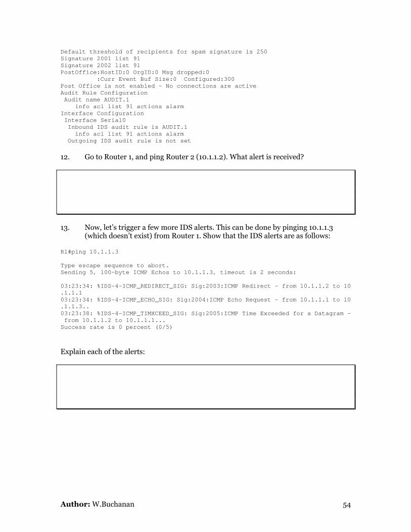
Default threshold of recipients for spam signature is 250 Signature 2001 list 91 Signature 2002 list 91 PostOffice:HostID:0 OrgID:0 Msg dropped:0 :Curr Event Buf Size:0 Configured:300 Post Office is not enabled - No connections are active Audit Rule Configuration Audit name AUDIT.1 info acl list 91 actions alarm Interface Configuration Interface Serial0 Inbound IDS audit rule is AUDIT.1 info acl list 91 actions alarm Outgoing IDS audit rule is not set 12. Go to Router 1, and ping Router 2 (10.1.1.2). What alert is received? 13. Now, let’s trigger a few more IDS alerts. This can be done by pinging 10.1.1.3
(which doesn’t exist) from Router 1. Show that the IDS alerts are as follows:
R1#ping 10.1.1.3 Type escape sequence to abort. Sending 5, 100-byte ICMP Echos to 10.1.1.3, timeout is 2 seconds: 03:23:34: %IDS-4-ICMP_REDIRECT_SIG: Sig:2003:ICMP Redirect - from 10.1.1.2 to 10 .1.1.1 03:23:34: %IDS-4-ICMP_ECHO_SIG: Sig:2004:ICMP Echo Request - from 10.1.1.1 to 10 .1.1.3.. 03:23:38: %IDS-4-ICMP_TIMXCEED_SIG: Sig:2005:ICMP Time Exceeded for a Datagram - from 10.1.1.2 to 10.1.1.1... Success rate is 0 percent (0/5)
Explain each of the alerts:
Author: W.Buchanan 54

Lab 21: PGP Encryption First download the PGP software from: http://www.dcs.napier.ac.uk/~bill/zips/PGPcmdln_6.5.8_Win32_FW.zip Unzip it, and install it to the system.
Objectives Activity Completed (yes/no) 1. Generate public and private 1024-bit RSA keys. 2. Generate an ASCII version of your public key.
3. Pass your public-key to some else.
4. Produce a text file, and encrypt it with the other person’s public key.
5. Get the other person to decrypt the encrypted message, using their private key.
6. Send another person an email with an encrypted file, and see if they can decrypt it.
Generating keys Both the public and the private keys are generated with: pgp -kg Initially, the user is asked about the key sizes. The larger the key the more secure it is. A 1024 bit key is very secure. C:> pgp -kg Pretty Good Privacy(tm) Version 6.5.8 (c) 1999 Network Associates Inc. Uses the RSAREF(tm) Toolkit, which is copyright RSA Data Security, Inc. Export of this software may be restricted by the U.S. government. Choose the public-key algorithm to use with your new key 1) DSS/DH (a.k.a. DSA/ElGamal) (default) 2) RSA Choose 1 or 2: 2 Pick your RSA key size: 1) 1024 bits- High commercial grade, secure for many years 2) 2048 bits- "Military" grade, secure for forseeable future Choose 1, 2, or enter desired number of bits: 1 Generating a 1024-bit RSA key.
Author: W.Buchanan 55

Next, the program asks for a user ID, which is normally the users name and his/her password. This ID helps other users to find the required public key. You need a user ID for your public key. The desired form for this user ID is your name, followed by your E-mail address enclosed in <angle brackets>, if you have an E-mail address. For example: John Q. Smith <[email protected]> Enter a user ID for your public key: Fred Smith <[email protected]> Enter the validity period of your signing key in days from 0 - 10950 0 is forever (the default is 0): 0
Next PGP also asks for a pass phrase, which is used to protect the private key if another person gets hold of it. No person can use the secret key file, unless they know the pass phrase. Thus the pass phase is like a password but is typically much longer. The phase is also required when the user is encrypting a message with his/her private key. You need a pass phrase to protect your RSA secret key. Your pass phrase can be any sentence or phrase and may have many words, spaces, punctuation, or any other printable characters. Enter pass phrase: fred Enter same pass phrase again: fred The public and private keys are randomly derived from measuring the intervals between keystrokes. For this the software asks for the user to type a number of keys. Note that key generation is a lengthy process. PGP needs to generate some random data. This is done by measuring the time intervals between your keystrokes. Please enter some random text on your keyboard until the indicator reaches 100%. Press ^D to cancel 100% of required data Enough, thank you. ................******* ........******* Make this the default signing key? (Y/n) Y Key generation completed.
This has created a public and a secret keyring (pubring.rkr and secring.skr). Generating a text file of your public key The -kx option can be used to extract the new public key from the public key ring and place it in a separate public key file, which can be send to people who want to send an encrypted message to the user. C:>pgp -kx fred Pretty Good Privacy(tm) Version 6.5.8 (c) 1999 Network Associates Inc. Uses the RSAREF(tm) Toolkit, which is copyright RSA Data Security, Inc. Export of this software may be restricted by the U.S. government. Extracting from keyring 'c:\windows\pubring.pkr', userid "fred". Extract the above key(s) into which file? fred.pgp Output file 'fred.pgp' already exists. Overwrite (y/N)? y Key extracted to file 'fred.pgp'.
Author: W.Buchanan 56

The public key file (fred.pgp) can be sent to other users, and can be added to their public key rings. Care must be taken never to send anyone a private key, but even if it is sent then it is still protected by the pass phase. An example public key is: -----BEGIN PGP PUBLIC KEY BLOCK----- Version: PGP 6.5.8 mQCNAzwKsS8AAAEEAM82ZVzbZEWwEluK6a2ZX5vv+KiyPvDGEnnb2Ypv20caIc2T Am3lUqKaXlGvlIEqAzbZ/mWK44U0tBDJZQ0ORW6n3HSVXb+dNdkMVrs+GZNXoal/ dJjU1WnA5xIkory9JQ3sQHbGoDkOEHEI0ecWfTik5yjk9alVotAxb0ckFVUvAAUR tBpGcmVkIFNtaXRoIDxmcmVkQGhvbWUuY29tPokAlQMFEDwKsS/QMW9HJBVVLwEB B6AEAK6dDluai0cQz7RHL3DntWR05HtSVPSTrYvDO5JXA/bk6NW9+fY42WWlD/Z5 cDV/BpuUHdhJ49I+eTbV9IO2JxEkkwN5X9S0dUA3d8AeWuH/SoAb9J3B8ePindXb GrbC/xDDu0AsGFZl1VjNK78N/pdnPPKuCcYlwT9qnL0k458N =sSxK -----END PGP PUBLIC KEY BLOCK-----
Add a public key to your public key ring Next, another user, say Bert, adds Fred’s public key to their public keyring. This is achieved using the –ka option, as given next: C:> pgp -ka fred.pgp Pretty Good Privacy(tm) Version 6.5.8 (c) 1999 Network Associates Inc. Uses the RSAREF(tm) Toolkit, which is copyright RSA Data Security, Inc. Export of this software may be restricted by the U.S. government. Looking for new keys... RSA 1024 0x2415552F 2001/12/02 Fred Smith <[email protected]> sig? 0x2415552F (Unknown signator, can't be checked) keyfile contains 1 new keys. Add these keys to keyring ? (Y/n) Y New userid: "Fred Smith <[email protected]>". New signature from keyID 0x2415552F on userid Fred Smith <[email protected]> Keyfile contains: 1 new key(s) 1 new signatures(s) 1 new user ID(s) Summary of changes : New userid: "Fred Smith <[email protected]>". New signature from keyID 0x2415552F on userid Fred Smith <[email protected]> Added : 1 new key(s) 1 new signatures(s) 1 new user ID(s) Fred’s key has been added to Bert’s public key ring. This ring can be listed with the –kv, as given next:
Author: W.Buchanan 57

C: >pgp -kv Pretty Good Privacy(tm) Version 6.5.8 (c) 1999 Network Associates Inc. Uses the RSAREF(tm) Toolkit, which is copyright RSA Data Security, Inc. Export of this software may be restricted by the U.S. government. Type bits keyID Date User ID RSA 1024 0xDB2936DB 2001/12/02 *** DEFAULT SIGNING KEY *** Bert <[email protected]> RSA 1024 0x2415552F 2001/12/02 Fred Smith <[email protected]> 2 matching keys found. Encrypting a file Next, a message can be send to Fred, using his public key. C: >edit hello.txt <add some text here> and then encrypted using: C: >pgp -ea hello.txt Pretty Good Privacy(tm) Version 6.5.8 (c) 1999 Network Associates Inc. Uses the RSAREF(tm) Toolkit, which is copyright RSA Data Security, Inc. Export of this software may be restricted by the U.S. government. Recipients' public key(s) will be used to encrypt. A user ID is required to select the Recipient's public key. Enter the Recipient's user ID: fred Key for user ID: Fred Smith <[email protected]> 1024-bit RSA key, Key ID 0x2415552F, created 2001/12/02 WARNING: Because this public key is not certified with a trusted signature, it is not known with high confidence that this public key actually belongs to: "Fred Smith <[email protected]>". Are you sure you want to use this public key (y/N)?y Transport armor file: hello.txt.asc An example of the file produced is:
-----BEGIN PGP MESSAGE----Version: PGP 6.5.8 hQCMA9Axb0ckFVUvAQP+PHvEd5kKte1TdN/zRTQoKCmNjDhh+HUFjTPwNRXKMlAj BqqPS2KFl7AfqxQegscleU7RSBThOW/ORrN6lnnWxvm/aaLgJ32Cs8U+eFUOZn8P Y/1YciNPx8hZ89SII0fVxO6YHTXWkn2gmfTW8EQRgrvy/9rOnY1qlTgl1313Ijak L/nQCfyL/GiE904gW9O92KEYk57hfsViQ1OZuV8eUxQvUMschtfV5Vpewc/UMxaj =6rIG -----END PGP MESSAGE-----
Author: W.Buchanan 58

Lab 22: .NET Security The Microsoft .NET environment now offers an excellent alternative to Java in producing portable and secure code. The .NET environment is typically stored below the: c:\windows\microsoft.net\framework folder, with a subfolder for the current version. If you have Version 1.1, open a command promopt and try the csc.exe command: c:\> csc.exe If this does not work then the path has not been set. It will work, though, if you change the current directory to: c:\> cd \windows\microsoft.net\framework\v1.1.4322 then execute it again, and you should get something like the following: C:\WINDOWS\Microsoft.NET\Framework\v1.1.4322>csc Microsoft (R) Visual C# .NET Compiler version 7.10.3052.4 for Microsoft (R) .NET Framework version 1.1.4322 Copyright (C) Microsoft Corporation 2001-2002. All rights reserved. fatal error CS2008: No inputs specified To test the compiler create a simple program, such as: using System; namespace ConsoleApplication3 { class Class1 { static void Main(string[] args) { System.Console.WriteLine("Hello"); System.Console.ReadLine(); } } } Next compile the program with: C:\>csc test.cs Microsoft (R) Visual C# .NET Compiler version 7.10.3052.4 for Microsoft (R) .NET Framework version 1.1.4322 Copyright (C) Microsoft Corporation 2001-2002. All rights reserved. and run it: C:\>test.exe Hello
Author: W.Buchanan 59
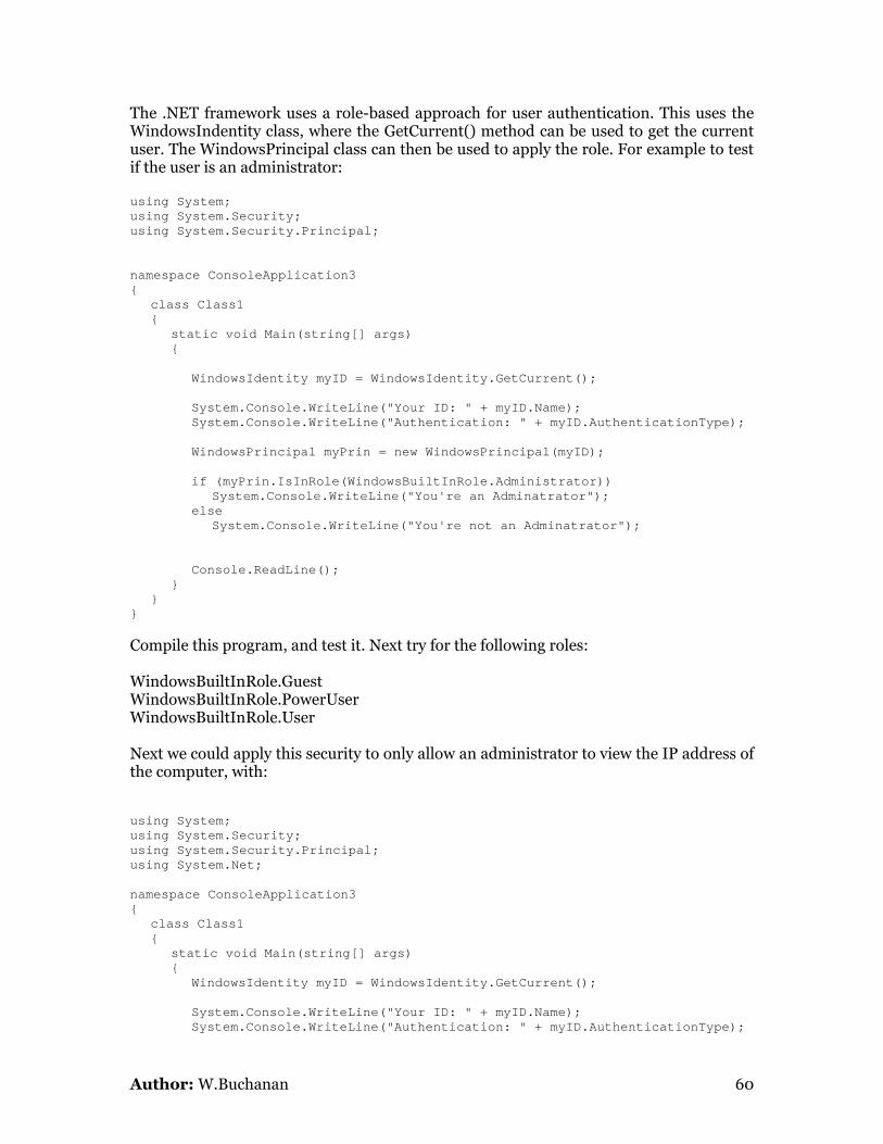
The .NET framework uses a role-based approach for user authentication. This uses the WindowsIndentity class, where the GetCurrent() method can be used to get the current user. The WindowsPrincipal class can then be used to apply the role. For example to test if the user is an administrator: using System; using System.Security; using System.Security.Principal; namespace ConsoleApplication3 { class Class1 { static void Main(string[] args) { WindowsIdentity myID = WindowsIdentity.GetCurrent(); System.Console.WriteLine("Your ID: " + myID.Name); System.Console.WriteLine("Authentication: " + myID.AuthenticationType); WindowsPrincipal myPrin = new WindowsPrincipal(myID); if (myPrin.IsInRole(WindowsBuiltInRole.Administrator)) System.Console.WriteLine("You're an Adminatrator"); else System.Console.WriteLine("You're not an Adminatrator"); Console.ReadLine(); } } } Compile this program, and test it. Next try for the following roles: WindowsBuiltInRole.Guest WindowsBuiltInRole.PowerUser WindowsBuiltInRole.User Next we could apply this security to only allow an administrator to view the IP address of the computer, with: using System; using System.Security; using System.Security.Principal; using System.Net; namespace ConsoleApplication3 { class Class1 { static void Main(string[] args) { WindowsIdentity myID = WindowsIdentity.GetCurrent(); System.Console.WriteLine("Your ID: " + myID.Name); System.Console.WriteLine("Authentication: " + myID.AuthenticationType);
Author: W.Buchanan 60

WindowsPrincipal myPrin = new WindowsPrincipal(myID); if (myPrin.IsInRole(WindowsBuiltInRole.Administrator)) { string strHostName = Dns.GetHostName(); IPHostEntry ipEntry = Dns.GetHostByName(strHostName); IPAddress [] addr = ipEntry.AddressList; System.Console.WriteLine("IP: " + addr[0]); } else System.Console.WriteLine( "Sorry ... you have no permissions for this"); } } } Run this program, and view the output.
Author: W.Buchanan 61

Lab 23: Setting up SPAN port on Switches Author: L.Saliou/W.Buchanan A network-based Intrusion Detection System is typically placed on the SPAN port of a switch. For example the following shows how to setup a switch to monitor three VLANs, and sent the traffic to the port 24: enable vlan database vlan 10 name DMZ vlan 20 name private
Snort
Vlan 30 name Fred exit configure terminal hostname AccessSwitch interface range fastEthernet 0/1 - 06 switchport mode access switchport access vlan 10 description connected to vlan 10 no shutdown exit interface range fastEthernet 0/7 - 12 switchport mode access switchport access vlan 20 description connected to vlan 20 no shutdown exit interface range fastEthernet 0/13 - 19 switchport mode access switchport access vlan 30 description connected to vlan 30 no shutdown exit interface vlan 1 ip address 192.168.1.1 255.255.255.0 no shutdown exit ip default-gateway 192.168.1.2 interface fastethernet 0/23 switchport trunk encapsulation dot1q switchport mode trunk description connected to the router and trunking no shutdown exit monitor session 1 source vlan 1 , 10, 20 rx monitor session 1 destination interface fastEthernet 0/24 The main objective of this lab is to setup three hosts on the switch, and another host should monitor the traffic. Conduct the following: 1. Use Ethereal or Snort to verify that the traffic is being captured. 2. Use Snort to capture any WWW based activity. If required use a basic client and
server between the two hosts. Otherwise setup the IIS. 3. Use Snort to pickup network activity which has the word “Intel” in the payload. 4. Use Snort to detect ping’ing activity on the network.
Author: W.Buchanan 62

Lab 24: Wireless Networks Author: W.Buchanan Split into groups (Group A and Group B), and implement the following: Group A: 1. With three hosts, set-up a wireless ad-hoc network named MyAdHoc. It should
have the following characteristics:
Subnet: 10.0.0.0 Subnet mask: 255.255.255.0
2. Create a shared folder on each machine, and mount this as a drive on each of the
other machines. Show the files can be transfer between the machines using the shared folders.
3. With the iPAQ, connect to the Ad-hoc network, and ping its presence from the
other machines. Group B: 1. With three hosts, and the wireless device which is connected to the pods, set-up
an infrastructure name NapierSoC. It should have the following characteristics:
Subnet: 192.168.0.0 Subnet mask: 255.255.255.0
2. Create a shared folder on each machine, and mount this as a drive on each of the
other machines. Show the files can be transfer between the machines using the shared folders.
3. With the iPAQ, connect to the infrastructure network, and ping its presence from
the other machines.
Author: W.Buchanan 63

Lab 25: IPSec on a PIX Author: W.Buchanan
Details Aim: Defining IPSec on a PIX
Activities In groups of three, select a router to program, and setup the network given in Figure 18. Each person should program one of the routers/PIX.
Router 2
Router 1
PIX
e0 [172.16.0.1/24]
e1 [10.0.0.1/16]
e2 [192.168.1.1]
e0 [172.16.0.2/24]
e0 [10.0.0.2/16]
Host
inside
outside
Figure 18: PIX pod example
Note: you may have to erase the configuration on the devices, before you start. To do this use the commands: erase startup reload
on the routers, and: write erase reload
on the PIX. The outline configuration of Router 2 is (146.176.165.230:2016):
Author: W.Buchanan 64

enable config t hostname outsideR int e0 ip address 172.16.0.2 255.255.255.0 no shut exit router rip network 172.16.0.0 exit ip route 0.0.0.0 0.0.0.0 172.16.0.1 line vty 0 4 password fred login exit
The outline configuration of Router 1 is (146.176.165.230:2015): enable config t hostname insideR int e0 ip address 10.0.0.2 255.255.0.0 no shut exit router rip network 10.0.0.0 exit ip route 0.0.0.0 0.0.0.0 10.0.0.1 line vty 0 4 password fred login exit
and the PIX is (146.176.165.230:2014): enable config t hostname myPIX interface ethernet0 auto interface ethernet1 auto interface ethernet2 auto nameif ethernet0 outside security0 nameif ethernet1 inside security100 nameif ethernet2 dmz security50 hostname pixfirewall ip address outside 172.16.0.1 255.255.255.0 ip address inside 10.0.0.1 255.255.0.0 ip address dmz 192.168.1.1 255.255.255.0 global (outside) 1 192.168.2.20-192.168.2.254 nat (inside) 1 10.0.0.0 255.255.0.0 0 0 route outside 0.0.0.0 0.0.0.0 172.16.0.2 1
2. Next verify the NAT translation by using the following command on the PIX device: pixfirewall# show xlate 1 in use, 1 most used Global 192.168.2.20 Local 10.0.0.2 3. Now go to Router 1 (the inside router), and telnet from there to Router 2: insideR#telnet 172.16.0.2
Author: W.Buchanan 65

Trying 172.16.0.2 ... Open User Access Verification Password: outsideR> The ends of an IPSec connection can be a router, a PIX device, or any other host which supports IPSec. In Cisco devices, the main configuration command used for setting up IPSec is isakmp. On a PIX, the basic usage is: pixfirewall(config)# isakmp Usage: isakmp policy <priority> authen <pre-share|rsa-sig> isakmp policy <priority> encrypt <aes|aes-192|aes-256|des|3des> isakmp policy <priority> hash <md5|sha> isakmp policy <priority> group <1|2|5> isakmp policy <priority> lifetime <seconds> isakmp key <key-string> address <ip> [netmask <mask>] [no-xauth] [no- config-mode] isakmp enable <if_name> isakmp identity <address|hostname|key-id> [<key-id-string>] isakmp keepalive <seconds> [<retry seconds>] isakmp nat-traversal [<natkeepalive>] isakmp client configuration address-pool local <poolname> [<pif_name>] isakmp peer fqdn|ip <fqdn|ip> [no-xauth] [no-config-mode] 4. APPLY TO IKE TO AN INTERFACE. Initially IKE is enabled on an interface (such as on the outside interface): isakmp enable outside
5. DEFINE SHARED KEY FOR DIFFIE-HELLMAN. Next the Diffie-Hellman process requires a key-string, such as ABC&FDD, which will be used with a peer at the address of 176.16.0.2 (which has a subnet mask of 255.255.255.255 so that it is only one host): isakmp key ABC&FDD address 176.16.0.2 netmask 255.255.255.255
6. DEFINE RSA HOST/ADDRESS. The other side will use the same pre-shared key. Next, if RSA encryption is being used for the public-key encryption, the hostname, or its address can be used to generate the RSA encryption. This is achieved using an address with: isakmp identity address
7. DEFINE POLICY NUMBER. Each IKE has a policy number, where a 1 is the highest priority. Thus a higher value is typically used so that higher priorities can inserted at a future time. The following defines a policy number of 5 and that a pre-shared key is used (otherwise rsa-sig can be defined): isakmp policy 5 authen pre-share
8. DEFINE ENCRYPTION TYPE. Then the encryption type can be defined, such as for the DES encryption algorithm (others include aes, aes-192, aes-256, and 3des):
Author: W.Buchanan 66

isakmp policy 5 encrypt des
9. DEFINE HASHING FUNCTION. Next the hashing technique needs to be defined, as this will be used in the authentication process. The method methods are MD5 and SHA. As SHA has a larger hash code, and thus has less chance of creating the same signature for different unhashed values, it is typically used for enhanced security. Thus to define SHA: isakmp policy 5 hash sha
10. DEFINE DIFFIE-HELLMAN TYPE. Next the Diffie-Hellman method type is defined. For 768-bit Diffie-Hellman a Group 1 is used, while 1024-bit Diffie-Hellman uses Group 2, and 1582-bit Diffie-Hellman uses Group 5. Thus to setup Group 1 settings: isakmp policy 5 group 1
11. DEFINE LEASE TIME. Finally the default lifetime is defined in terms of seconds. Thus to setup a period of 1 day (86,400 seconds) the following can be defined: isakmp policy 5 lifetime 86400
12. VIEWING ISAKMP. Next we can exit from the configuration mode, and view the ISAKMP settings with: show isakmp
Defining IPSec Once the IKE is setup, the IPSec parameters can be defined. First we must allow the IPsec packets to pass through the PIX. Normally these would be interrupted by ACLs, which must be bypassed. To do this the following is used: sysopt connection permit-ipsec
The crypto command is then used to define the encryption used, and define a mapping. Its usage is: Usage: [ show ] crypto { ca | dynamic-map | ipsec | isakmp | map | sa } ... show crypto engine [verify] [ show | clear ] crypto interface [counters] The first configuration defines the security protocol defined between the peers. The following defines a transform set named MYIPSECFORMAT which uses DES for encapsulating security payload (ESP) and SHA for the authentication: crypto ipsec transform-set MYIPSECFORMAT esp-des esp-sha-hmac
13. DEFINE CRYPTO MAP. Next a crypto map can be defined, where MYIPSEC defines the name associated with the map and 10 is a sequence number. These sequence numbers allow different crypto combinations to be set for different peers which make
Author: W.Buchanan 67

connections on the interface that has the crypto map applied. There can only be crypto map on each interface, thus sequence number blocks can apply different policies to a specific crypto map: crypto map MYIPSEC 10 ipsec-isakmp
14. DEFINE ACCESS CONTROL LIST. Next the access control list (number 111) can be defined to specify the traffic which will be encrypted. In the following traffic from 10.0.0.0/24 to 176.16.0.0/24 will be encrypted. access-list 111 permit ip 10.0.0.0 255.255.255.0 176.16.0.0 255.255.255.0
15. ASSOCIATE ACCESS CONTROL LIST. After this, an access list number can be defined (in this case it is 111), where anything matching this list will either be encrypted (for outgoing data) or decrypted (for incoming data) as defined by the crypto map block (which is sequence number 10). Thus we can have different security settings depending on the sequence number: crypto map MYIPSEC 10 match address 111
16. DEFINE PEER FOR CRYPTO LIST. Next the peer which is associated with the crypto map security policy defined: crypto map MYIPSEC 10 set peer 176.16.0.2
17. DEFINE PEER FOR CRYPTO LIST. Next the type of hashing and/or encoding is defined using the transform mapping: crypto map MYIPSEC 10 set transform-set MYIPSECFORMAT
18. APPLY ON AN INTERFACE. Next the crypto map can be applied onto an interface (only one is allowed on each interface): crypto map MYIPSEC interface outside
Modifying Router 2 19. DEFINE CRYPTO POLICY. Once the PIX is setup, the router on the other end can be setup for IPSec. The commands used on Router 2 are then: crypto isakmp policy 100 hash sha authentication pre-share
20. DEFINE PRE-SHARE KEY. Then the pre-share key for Diffie-Hellman is setup: crypto isakmp key ABC&FDD address 176.16.0.1
and the transform set is defined with:
Author: W.Buchanan 68

crypto ipsec transform-set mine esp-des
21. DEFINE CRYPTO MAP Next the crypto map can be setup with: crypto map mymap 110 ispec-isakmp set peer 176.16.0.1 set transform-set mine match address 110
22. DEFINE ACCESS-LIST. The access lists can be added with: access-list 101 permit ahp host 172.16.0.1 host 172.1.0.2 access-list 101 permit esp host 172.16.0.1 host 172.1.0.2 access-list 101 permit udp host 172.16.0.1 host 172.1.0.2 eq isakmp access-list 110 permit tcp host 172.16.0.0 0.0.0.255 172.1.0.2 0.0.0.255 access-list 110 deny ip any any
23. APPLY ON AN INTERFACE. This and the crypto map can then be applied to an interface with: interface fa0/1 ip address access-group 101 in crypto map mymap
23. DEBUG. Next try and get the connection to work. The main debug commands are: show crypto ipsec sa Show security associations. show crypto isakmp sa Shows ISAKMP policy debug crypto isakmp Shows debug information for ISAKMP. debug crypto ipsec Show debug information for IPSec. clear crypto ipsec sa Clears associations.
Author: W.Buchanan 69

Lab 26: RADIUS on a WAP (using CLI) Author: W.Buchanan
Details Aim: Enable RADIUS and LEAP Authentication on a Cisco Aironet using CLI Figure 1 shows the setup, where the wireless node must connect to the Aironet device, and use LEAP authentication. The parameters to set on the Aironet device are: SSID: APskills IP address: 192.168.1.110/24 WEP key: AAAAAAAAAA (64-bit WEP key) Authentication: LEAP
Wirelessnode192.168.1.115/24
Cisco Aironet 1200192.168.1.110/24
192.168.1.111/24192.168.1.112/24
Figure 1
Step 1. To setup a WEP key of AAAAAAAAAA, and IP address of 192.168.1.110, and open authentication. A connection is made with the Access Point, and its SSID (APskills), IP address and subnet mask can be set. This can be done either with the CLI of: interface Dot11Radio0 encryption key 1 size 40bit AAAAAAAAAA transmit-key encryption mode ciphers wep40 no ssid tsunami ssid APskills authentication network-eap eap_methods
Author: W.Buchanan 70

guest-mode exit channel 1 station-role root exit interface BVI1 ip address 192.168.1.110 255.255.255.0 exit ip http server 2. After which the AAA can be setup with: hostname ap aaa new-model aaa group server radius rad_eap server 192.168.1.110 auth-port 1812 acct-port 1813 exit aaa group server radius rad_mac exit aaa group server radius rad_acct exit aaa group server radius rad_admin exit aaa group server radius dummy server 192.168.1.110 auth-port 1812 acct-port 1813 exit aaa group server radius rad_pmip exit aaa authentication login eap_methods group rad_eap aaa authentication login mac_methods local aaa authorization exec default local aaa authorization ipmobile default group rad_pmip aaa accounting network acct_methods start-stop group rad_acct aaa session-id common 3. Next RADIUS is setup as the local server with (using a shared key of sharedkey): radius-server local nas 192.168.1.110 key sharedkey user aaauser password aaapass user bbbuser password bbbpass exit radius-server host 192.168.1.110 auth-port 1812 acct-port 1813 key sharedkey exit 4. Next the wireless client can be setup by first setting the WEP key (Figure 2). 5. Next authentication is defined with LEAP (Figure 3), where the username is
defined as aaauser and the password is aaapass. 6. The wireless device should be about to ping itself and the access point, such as: C:\>ping 192.168.1.110 Pinging 192.168.1.110 with 32 bytes of data:
Author: W.Buchanan 71

Reply from 192.168.1.110: bytes=32 time=2ms TTL=255 Reply from 192.168.1.110: bytes=32 time=1ms TTL=255 Reply from 192.168.1.110: bytes=32 time=1ms TTL=255 Reply from 192.168.1.110: bytes=32 time=1ms TTL=255 Ping statistics for 192.168.1.110: Packets: Sent = 4, Received = 4, Lost = 0 (0% loss), Approximate round trip times in milli-seconds: Minimum = 1ms, Maximum = 2ms, Average = 1ms C:\>ping 192.168.1.115 Pinging 192.168.1.115 with 32 bytes of data: Reply from 192.168.1.115: bytes=32 time<1ms TTL=128 Reply from 192.168.1.115: bytes=32 time<1ms TTL=128 Reply from 192.168.1.115: bytes=32 time<1ms TTL=128 Reply from 192.168.1.115: bytes=32 time<1ms TTL=128 Ping statistics for 192.168.1.115: Packets: Sent = 4, Received = 4, Lost = 0 (0% loss), Approximate round trip times in milli-seconds: Minimum = 0ms, Maximum = 0ms, Average = 0ms 7. The wireless access point should also be able to show the association such as: ap#show dot11 assoc 802.11 Client Stations on Dot11Radio0: SSID [APskills] : MAC Address IP address Device Name Parent State 0090.4b54.d83a 192.168.1.115 4500-radio - self EAP-Assoc Others: (not related to any ssid) 8. Verify that the wireless node can be pinged, and show that if the username and
password is incorrect, that it will not be authenticated.
9. Add another wireless client to the wireless network, and make sure that it can be pinged. Next add an access list which bars it from the network with an access-list which includes its MAC address, such as (where the MAC address of the node must be added to the access-list):
access-list 701 deny 0090.4b54.d83a 0.0.0 access-list 701 permit 0.0.0 ffff.ffff.ffff 0.0.0 ffff.ffff.ffff int d0 l2-filter bridge-group-acl bridge-group 1 bridge-group 1 subscriber-loop-control bridge-group 1 input-address-list 1101
Author: W.Buchanan 72

10. Show that the node cannot get access to the wireless network.
Figure 2
Figure 3
Author: W.Buchanan 73

The following are screen shots taken from the Web interface which show the connections:
Figure 4
Figure 5
Author: W.Buchanan 74

Figure 6
Figure 7
Author: W.Buchanan 75

Figure 8
Figure 9
Author: W.Buchanan 76

Figure 10: Associations
The configuration was then tested with a different username, and would not connect. Thus verifying the setup.
f
Implementation 2 This is achieved as in the steps defined in Figure 5-9, and gives the same output as the CLI method.
Author: W.Buchanan 77

Author: W.Buchanan 78

Some configs ------------- ACL TELNET-------------- Router 3 config t hostname "Router3" interface FastEthernet0/0 ip address 176.16.0.1 255.255.255.0 duplex auto speed auto no shut interface Serial0/0 ip address 192.168.0.2 255.255.255.0 ip access-group 101 in no shut clockrate 56000 interface Serial0/1 no ip address shutdown exit router rip network 176.16.0.0 network 192.168.0.0 access-list 101 deny tcp 192.168.0.0 0.0.0.255 176.16.0.0 0.0.0.255 eq telnet access-list 101 permit ip any any line vty 0 4 password fred login end Router 2: config t hostname "Router2" interface FastEthernet0/0 ip address 176.16.0.2 255.255.255.0 no shut interface Serial0/0 no ip address shutdown exit router rip network 176.16.0.0 exit line vty 0 4 password fred login end
Author: W.Buchanan 79

Router 1: config t hostname "Router1" interface FastEthernet0/0 no ip address shutdown interface Serial0/1 ip address 192.168.0.1 255.255.255.0 no shut interface Serial0/2 no ip address shutdown exit router rip network 192.168.0.0 exit line vty 0 4 password fred login end ------------- ACL ICMP-------------- Router 3 config t hostname "Router3" interface FastEthernet0/0 ip address 176.16.0.1 255.255.255.0 ip access-group 100 in duplex auto speed auto no shut interface Serial0/0 ip address 192.168.0.2 255.255.255.0 no shut clockrate 56000 interface Serial0/1 no ip address shutdown exit router rip network 176.16.0.0 network 192.168.0.0 access-list 100 deny icmp 176.16.0.0 0.0.0.255 host 192.168.0.1 echo access-list 100 permit ip any any line vty 0 4 password fred login end Router 2:
Author: W.Buchanan 80

config t hostname "Router2" interface FastEthernet0/0 ip address 176.16.0.2 255.255.255.0 no shut interface Serial0/0 no ip address shutdown exit router rip network 176.16.0.0 exit line vty 0 4 password fred login end Router 1: config t hostname "Router1" interface FastEthernet0/0 no ip address shutdown interface Serial0/1 ip address 192.168.0.1 255.255.255.0 no shut interface Serial0/2 no ip address shutdown exit router rip network 192.168.0.0 exit line vty 0 4 password fred login end ------------- NAT -------------- ROUTER 1 config t hostname Router1 interface s0/1 ip address 172.16.0.1 255.255.255.0 no shut exit ip route 0.0.0.0 0.0.0.0 172.16.0.2 ROUTER 3--------------- config t
Author: W.Buchanan 81

hostname Router3 interface fa0/0 ip address 10.0.0.2 255.255.255.0 no shut ip nat inside exit interface s0/0 ip address 172.16.0.2 255.255.255.0 ip nat outside clockrate 56000 no shut exit ip nat pool MyPool 192.168.16.10 192.168.16.254 netmask 255.255.255.0 ip nat inside source list 1 pool MyPool access-list 1 permit any !access-list 1 permit 172.16.88.0 0.0.0.255 ROUTER 2------------ config t hostname Router2 interface fa0/0 ip address 10.0.0.1 255.255.255.0 no shut exit ip route 0.0.0.0 0.0.0.0 10.0.0.2
Author: W.Buchanan 82

Frame Relay/ISDN pods The frame relay/ISDN pods are arranged as in Figure 4. Note: DO NOT USE COPY RUNNING STARTUP, as this may reset the privileged password. If you change the privileged password, and save the configuration, please tell your lecturer as soon as possible. AT THE PRESENT ONLY PODS A and B ISDN, but all have Frame Relay.
Router 1
Router 2 Router 3
FA0/1 FA0/2 FA0/3
R1: E0 R2: E0 R3: E0
Seriallink
Ethernetlink
Seriallink
S0/0:
S0/0:
E0: E0:
S0/0:
S0/1:
S0/2:
FrameRelay
S0/1: S0/1:
BRI0:BRI0:
ISDN
Figure 19: Network Pod configuration
Please note that the pods may vary with their associated ports, so you may have to substitute FA0 for FA0/0 or E0. Also S0 may be replaced with S0/0, and S1 with S0/1. The pods have the following set-up (To be updated): Ethernet Serial ISDN/T1 Pod A Router 1 FA0/1 S0/0, S0/1, S0/2
Router 2 FA0/0 S0/0, S0/1 BRI0/0
Router 3 FA0/0 S0/0, S0/1 BRI0/0
Pod B
Router 1 FA0 S0, S1, S2
Router 2 FA0 S0, S1 BRI0
Router 3 FA0 S0, S1 BRI0
Pod C
Router 1 FA0 S0, S1, D2
Router 2 FA0 S0, S1 BRI0
Router 3 FA0 S0, S2 BRI0
Pod D
Router 1 FA0/0 S0/0, S0/1, S0/2
Router 2 FA0/0 S0/0, S0/1 BRI0/0
Router 3 FA0/0 S0/0, S0/1 BRI0/0
The ISDN number of the devices are:
Author: W.Buchanan 83

Pod A: Router 2: 555 1000 Router 3: 555 2000 Pod B: Router 2: 555 3000 Router 3: 555 4000
Accessing the routers The pods can be booked via the WWW page: http://www.dcs.napier.ac.uk/~bill/pods.html Note, the routers are accessed by: Pod A Router 1: telnet 146.176.165.228:2001 Router 2: telnet 146.176.165.228:2002 Router 3: telnet 146.176.165.228:2003 Switch: telnet 146.176.165.228:2004 Pod B Router 1: telnet 146.176.165.228:2005 Router 2: telnet 146.176.165.228:2006 Router 3: telnet 146.176.165.228:2007 Switch: telnet 146.176.165.228:2008 Pod C Router 1: telnet 146.176.165.228:2009 Router 2: telnet 146.176.165.228:2010 Router 3: telnet 146.176.165.228:2011 Switch: telnet 146.176.165.228:2012 Pod D Router 1: telnet 146.176.165.228:2013 Router 2: telnet 146.176.165.228:2014 Router 3: telnet 146.176.165.228:2015 Switch: telnet 146.176.165.228:2016
Author: W.Buchanan 84

PIX firewall pods The PIX firewall pods are arranged as in Figure 2. Note: DO NOT USE COPY RUNNING STARTUP, as this may reset the privileged password. If you change the privileged password, and save the configuration, please tell your lecturer as soon as possible.
Router 2
Router 1
PIX
e0 [outside]
e1 [inside]
e2 [inf2]
e0
e0
Host
inside
outside
Figure 2: Network Pod configuration
These are access by: PIX Pod A Router 1: telnet 146.176.165.230:2015 Router 2: telnet 146.176.165.230:2016 PIX: telnet 146.176.165.230:2014 Host: 192.168.1.201-204 PIX Pod B Router 1: telnet 146.176.165.230:2007 Router 2: telnet 146.176.165.230:2008 PIX: telnet 146.176.165.230:2013 Host: 192.168.1.201-204
Author: W.Buchanan 85

Author: W.Buchanan 86