LA-UR-93-3528 - Federation of American Scientists · · 2016-10-21LA-UR-93-3528 Title; Author(s):...
12
LA-UR- 93-3528 Title; Author(s): Subfniffed to: Prototype Explosives Detection System Based on Nuclear Resonance Absorption in Nitrogen R. E. Morgado, .G. Arnone, C. C. Cappiello, S. D. Gardner, C. L. Holhs, L. E. Ussery, J. M. White, J. D. Zahrt, and R. A. Krauss SPIE Conference I october 5-8. 1993 Innsbruck, AUSTRIA DlSTR16UmON OF THIS DOCUMENT IS UNLlh:tl~ .—..- ~-~;=$ .’ .=z- LOSAlamos NATIONAL LABORATORY Loo Alwnw National bbomory, M dfltnwtiw WotVqud Opporhmy @n@dpr, IS opotmd by Iho Urwmwj of CdNotnI@ for M US Dopmnont of Erwrgy undw cw)trtol W. 740S@4030t BV monw d Ihlt Mdo, NM PWIWIW f~mzos Ihat lh$ U S Govomnont rotdno a IWWWISIVO, roydty.fma Ikxm to pubtish w roptoda Iiw puhU8h9dtom of fhls cantrlbutlofi Ofto dbw Othws to M to, 10! U 8 Oovwrvnont pwpoaa Tho Los Almnoa NattoMl Lsbomtow rwls t~ h ** H M Mb@ M ti P.*M uti m wa ot Iti US IhtwIfnont01I?nofw FmMOmono 9TMOUMI
Transcript of LA-UR-93-3528 - Federation of American Scientists · · 2016-10-21LA-UR-93-3528 Title; Author(s):...
LA-UR- 93-3528
Title;
Author(s):
Subfniffed to:
Prototype Explosives Detection System Based onNuclear Resonance Absorption in Nitrogen
R. E. Morgado, .G. Arnone, C. C. Cappiello, S. D. Gardner,C. L. Holhs, L. E. Ussery, J. M. White, J. D. Zahrt,and R. A. Krauss
SPIE Conference
I october 5-8. 1993Innsbruck, AUSTRIA
DlSTR16UmON OF THIS DOCUMENT IS UNLlh:tl~
.—..-
~-~;=$
.’ .=z-
LOSAlamosNATIONAL LABORATORY
Loo Alwnw National bbomory, M dfltnwtiw WotVqud Opporhmy @n@dpr, IS opotmd by Iho Urwmwj of CdNotnI@ for M U S Dopmnont of Erwrgyundw cw)trtol W. 740S@4030t BV monw d Ihlt Mdo, NM PWIWIW f~mzos Ihat lh$ U S Govomnont rotdno a IWWWISIVO, roydty.fma Ikxm topubtish w roptoda Iiw puhU8h9dtom of fhls cantrlbutlofi Of to dbw Othws to M to, 10! U 8 Oovwrvnont pwpoaa Tho Los Almnoa NattoMl Lsbomtowrwls t~ h ** H M Mb@ M ti P.*M uti m wa ot Iti US IhtwIfnont01I?nofw
FmMOmono9TMOUMI
About This Report
This official electronic version was created by scanning the best available paper or microfiche copy of the original report at a 300 dpi resolution. Original color illustrations appear as black and white images. For additional information or comments, contact: Library Without Walls Project Los Alamos National Laboratory Research Library Los Alamos, NM 87544 Phone: (505)667-4448 E-mail: [email protected]

Prwtotype explosivesdetection systembased on nuclear rtsonance absorption in nitrogen
R E. Morgado, G. Amone, C. C. Cappicllo, S. D. Gardner,C. L. Hollas, L E. Ussery, J. M. White, J. IX Zahti.
Los AlarnosNationalLaboratory,Los Alamos,NM 87545
Federal Aviation Administration, AtlanticCity InternationalAiqmt,NJ 08405
ABSTR4CT
A~mtoype explosivesdetectionsystemthat was developedfor experimental evaluation of a nuclearrcsonaxeabamptiontechnique is descnlxd. TIE major subsystemsarea proton aoxletator ad beam tmnspat high-tempemtweproton target an airiine-luggage tomographic inspectio,lstatiomand an tige~=cssin~de~tion-dam subsystem. Thedetection systempcrforrnance,basedon a limited expdmental tcm is reported.
1. INTRODUCTION AND BACKGROUND
The development of the pre-psutotypeexplosivesdetectionsystemdescribedhere is basedon an arlier feasibilitystudy1 completed in 1989 in which the detectionof nitrogen in an explosive sirmdantwas demonstratedby seaming itwith a gamma-ray beam of an energycorrespondingto a nuclearresonancein nitrogen2.Our earlier studysdsosuggestedthat, by this technique, certain explosivesshouldbe distinguishablefrom irwt materials commonly encounteredin airlinepassengerluggage.
Scaling from theseresults,it was projected thata very high current (s=15 mA) proton accclcrator,usedin generating
the resonantenergy gamma rays,would be needed to meet the Federal Aviation Administration’s (FAA’s) 6s/bagtluoughput requirement. Ttw developmentalefforts describedhem were originally scopedto imlude the developmentofthis higharrent acceleratorfor a fully operational, semi-automatedprototypedetection systemfor testand evaluation in anahport However, due to budgetconstraints,* scopeof k project was scaledback to that of a laboratory testof areducedthroughput,non-automatedsystem, TIIIM, son of the majorsubsystemsthat havebeen developed incorporatesomt of thedesign featuresof sn airport prototype, e.g., the detector,data acquisition ad image processingsub~stcma,while the acceleratorand relatedsubsystemsare for a reducedthroughput(by an oder of magnitude), Nevertheless,this pre-pmtotype systempermits evaluation of many of the importantoperational chamcteristieaof an airport system wtuch is theprincipal objective of the project.
In the following, the phystcalbasisof the detectionotmept will be prwnted, followed by a descriptionof eaehmajor subsyatcmand its key performme characteristics,and some reads of our initial explosivesdetection testsfromwhich preliminary eonchtsionaon overall systcmperfornuwceMCdmwm
This FAA.sponsored project was a collaborative effort of the Los Alanms National Laboratory (LANL) ad tk SoreqNuclear Rewarch Center (SNRJ), Two variantsof thedctaxorfluggage inspectionsystemwere pursuedby th respectivecollaborators,but using a common aeeelemlorfgnmma-myproductionsystcm, The following addressestheLANL detcetionapproacmthe SNRC approachisaddressedin o companion~per,
DISC1,AIMER
‘1’hln report WAS prepared M urr nccounI of work fiponsored hy tin ngency of the (Jnlled SIuienouvernmrml Nehher the (Jn~(ed S(IIIM (Iovcrnmont nor nny agency Ihcreof, nor tiny of Iheiremployeet, mnkcn nny wnrrnnty, eRprcns or Implisd, or uxnumcrnany ICIIIII Iiuhillly or re~wnal”
hllhy for the twcuruuy. cumplclenerm, or usefuh!enn of any Infmmtilion, uppurnluh pruducl, m
prows dhwloned, or rcprewmtn Ihnt IIS une would not hrfrinnc privutely owned rlahln Refer.em:e herein to nrr y npeMlc comtnertxd product, procenn, or service hy Irmle nnmc, I rudemnrk,mnnufneturer, ,w othcrwlw doa not ntceaady conntltute or Im@y IIS embrrtemeni, recoin.mendtithm, or fttvorlrig hy the IJnhd Stu~es (Iovernmeril or nny figcncy ihereof ‘The VI*WB
and oplnhma wf authorn enpreanetl herehr do nol necenntirily stnte or rellecl Ihoee of Ihe
lJniM !ita~en (Merriment or arw timency therwf
2. PHYSICAL BASIS OF THE K)ETECTION CONCEPT
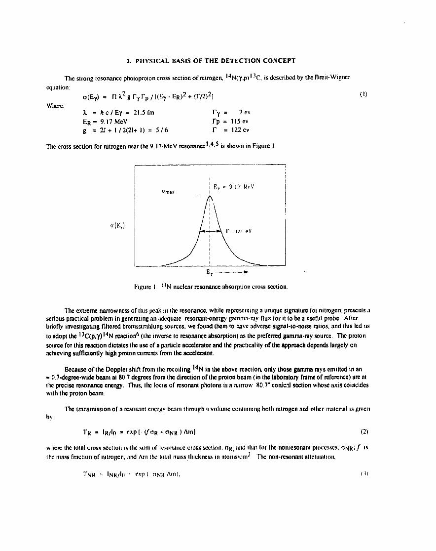
w strong rcsonanccphotoprotoncrosssectionof nit.rogcm14N(Y,P) 13C, is dcscrib~ by the Bmit-Wigncr
cqualion:
@Ey) = n A2 g ry rp / [(E7 - ER)2 + w)2]
whewA =Ac/Ey=21.5fm ry . 7 ev
ER = 9.17 MeV rp = 115CV
g = 2J+ l/2(21+1)= 5/6 r = 122 Cv
The crosssection for nitrogen mar the 9. 17-MeV resotumce3*4*5is shown in Figure 1.
13(EY)
I
o~*~IEY=91’7MPVI
A1-=122 ev
(1)
Figure I 14N nuclear rcsonanccabsqmon crosssection.
The extreme narrownessof this pmk In the rcsonancc, while rcpnscnIIng a unique signature for nitrogcrr, presents n
SCriOUSpractical pmblcm in gcncmtingan iid~qt]atc rcsonanl+xtergygamma-ray flux for it to be a useful probe Afterbriefly investigating filtered brcmsstmlrlungsources,we found them to have adverse signal-lo-noise ratios,and this Icd us
to adopI the 13C(p,Y) 14N rcactior$)(Ihc Inverse to resonanceabsorption)as [hc prcfermd gamma.ray source, The pro;on
sourcefor this reaction dictatesthe uscof a particleacceleratorand the practicality of k approachdependsIargcly onachieving sufllcicntly high protoncurrentsfrom the accelerator.
Bccauscof the Doppicr shifl from the recoiling 14N in the thovc rcactiott onfy thosegamma raysemitted in an= (},7dcgrcc-wide beam at WY degreesfrom the direction of the proton bciim (in Ihc laboratory frameof rcfcrcncc)are atlhc prcciscrcsonanccCrrergy, Thus, the !OC{L$ of ICSOIKWphotonsis 8 ruwrow !!0,7”conic?~sectionwhose il~k coincideswilh the proton beam
The transmissionof n resrrnmlcncrgv beam through a volume cwlt:umng bolh rulrqgcn rrnd olhcr nuilcrurl is glvcn
by.
‘1~ ❑ 1~/lo * (!xl)l ~rTR +(TN~ )Amj (2)
Nhere Ihe tolnl crossSW Iw IS the sum of tcsonancc cross section,(IR, and thot for Ilk nonicsonmllproccsscs,rrNR;j Is
Ihc IIUMS frac[ion of rutro~cn, nnd Am the toml IIMSS jluckrwss in rtloms/cn~2 ‘he rlon-resonanlisttcnnnllon.
‘1’NU + tNK/t[) - (*RI!( nN~ ,ftt)), ( 1)

can be determined indcpcrdcntly from sirnuhancous off-rcsonamx rncasurcmcnts of gamma-ray transmission, Thus, [hcnitrogen mass thickness is
AN = ~ Am = (1/cTR)?n (TNR /TR). (4)
The otT-resonance measurement is done by including barium fluoride in the 13C targe~ which produces 6.13 -,6.9-, and 7.1-McV gamma rays from the (p,ay) reaction in ‘9F. Transmission measurementsat theseenergiescan be extrapolated to theresonantenergy with s~lcicn[ accuracyto determine the nonresonantcontribution to the total crosssection. Transmissionrneasurmnentsthrough liquid nitrogenwere used in determining the effective UR for the actual measurementsystcm, Aschematicof the detection conecpt is shown in Fig 2.
3. OVERALL DESCRIPTION OF THE PROTOTYPE DETECTION SYSTEM
Figm 3 showsthe physical layout of the principal subsystemsof UK?detection systcm. The aecelcmtorproducesahorizontal,pulsedbeam of 1,75-McV protons,which passesthrough a foeusingquadrupolcand beam energy&bunchcr,and is turned downward by a combination bending and focusing magxx?tto producea -1 <m-dia beam spoton L!W}3Ctarget The resultantconical fan beam of gamma rays ISapproximately (within 10°) horizontal. Luggage is positionedontothe surfaceof a platform that incrementally rotates360” to produce multiple views of a slice of the luggage. The lug~qgcplatform is raisedor lowered by a constantincrvmcnt(the “slim” thickrms) between the successiverotationalscans,untilthe vertical crosssectionof the bag hasbeen scmncd
An may of gamma-ray detectorsis positiorwdon the locusof h resonantcnerl v beam, which spansapproximatelyone quadmntof the Ian beam. Individual detectoroutputsarc collcet~ prcproecsse~and transmitted to a computer workstationand temporality stored in the data acquisition work station Upon completion of a luggage inspection the data arctransmittedto a secondcomputer work station for a tomographic reconstructionshowing the luggagecontents,
Two images of the contcmsare produced: onc from the nonresonant(6- and 7-McV) giimrnamys, which providesa3-D image of the massdistribution within the inspectionvolume. and anotherof the nilrogcn distribution using theresonan~9,17-McV gamma rays, A nurnbcrof irnagc-processingtcclmiqucsare available (not autormtcd at this stogc ofdcvcloprncnt)to ascertainthe likelihood of the prc.scntcof csplosives.
A moredctnilcddescription of each of these mojor subsystems is given below
4. PROTON ACCELERATOR
The protonaccelerator usedfor (his project ~i~ an RFQ linac aequimd by Los Aliunos and modified ad partiiillyupgmdedby the FAA for resonanceabsorptionapplications, One objective of the pmjcct is to cvahmte the suitability formsonarm ttansrnissionmcasutwnentsof an RFQ Iinae (pulsedhm) in comparisonwith clcctmstatic twelcrators (C’Wbeam), The principal issueccntcrson the bcarncharacteristicslypieal of an RFQ acealcnttor,c,g,, the effect of bcmncmittancc (energyand geometric) and k micro. ,andtwlcro- stmturc of h piked beam on tnmsmissionIneiwrcmcnls,Other considerationsarc Mcrcnt beam stability, si~c, cost, C[C. llEse issues, tts well as it detailed description of the
ikxchmltor iwvd associatedbwun transportsystcm,am dlscusscdin detai] in an accom[hmvmg piper [2092-60],
S, PROTON” TARGET
The IUOSIpronnnent dcsigrr issue will] respect10the proton IWI;CI is its abilily 10w)tl~~[iitd he trcnl Io;d m~poscdby the high<urrcnt protonbeam The ongimd dcs~~nrcquirmcnt was for a 15-mA beam ‘]’hl!i \Vi\S SUbSC?llCliIl~ relil~cd10n 05- I,0 nti bl?illll, illlh(lll~h Ilk Iitrgcls used In Ihcsc Icsls incorporated sornc of Ihc Itxllurcs for Ihe higher power Icvcls()1Iwr designCOIWIdCmIiom I ncludc nUI\IIIIItiIIIOn of’ Utlwi}ntd SCrmdriry gnnutm-r,]yimducIIon in tl~ copperb:lckltl~:i~tdm.seof fabricm1011,

CONICAL FANBEAM
\
CARBON.13TARGFr
.. . . . . . . . . . .. . . . . . . . . . . . . . . .
ACCELERATOR
NITROGENOUS ._.MTERIA1.
GAMMA-RAYDHIXIDRS + C
Figure 2. Resonance-absoqxion-baseddeteetionconcept.
FIgUIQ 3 Ptysd configuration of the dctcetion syslcnl

Table I.Thick target coatings.
Target Set Layer
#1 123
45
6
#2 1
2
34
#3 1
234
56
Matcriat
Carbon 13Hafnium
GoldHafnium
Barium FluorideHafnium
Carbon 13Hafnium
Barium FluorideHafnium
Crubon 13Hafnium
GoldHafnium
Barium FluorideTa.rmdum
Thickness
148 pg/cm2300 A
5750 A
300 A1300A300 A
160 pg/cm2500 A
1300A
300 A
176 pg/cm2300 A
5750 A300 A
INO A10Um
The first generation designs were for powerdensities of54 kW/cm2. A watercooled copperbacking was used to dissipate the heat. The water istms.porwxt through channels machined into the backof the target to within 1.6 mm of its front face. Thechannel is in the form of a logarithmic spiral (see Fig4), which producesa tudmlent radial flow away fromh centml hot spot. Several coatingvariants werefabricated(see Table I) and tested Excitation curesandgamma-my spectrawere obtainedfor a samplefrom ~ch batch as a check on the thicknessofdepositedmaterials.
The Set # 1 duplicatesour eadicst design first
testedin 1991 al power Icvels of $1 kW/cm2 at theUniversity of !Xrmingham (UK) Dynamitron CWaccelerator. In the others, the 13C thicknesswasincreasedto aecorrunodatethe inherent proton energyspread (estimated to be >20 kev) asmciatcd with theaccelerating process (buxhing) of an RFQ accxlcmtorThe purpose of the hafnium is to facilitate intcrlaycrbonding;a layer of gold is necessaryto degradetheprotonenergy to that of the fluorine resonanceIcvcl;arrl, in #%,the tantalum is to further degrade the
protonenergy to S 500 kcV, so that thegamma-ray background inducedby the copper would be markedly lower. Thecoatings were applied by vapor depositionwith a four-hearthelectron-beamsource, A quartz crystal monitor was employedto eonlml coating thicknesses, The final thicknessesand coating densitieswere dctcrmincd from either protilomctcrmeasurementsof witness platesor from microbalancedifferential weights.
No degradationof Ihcse targetswas dcteacd in the courseof operational testingof the detection systcm;however,the heat loading was only moderate (generally Icss than 2 kW over a period ofs 200 h).
6. LUGGAGE MANIPULATOR
The hrggiigc manipulator (WCFig 5) sequentiallypositionsvertically and orients rotationally the Iuggagc m the
resonant energy beam to ob~ti thediffcrmt viewing directionsrequiredfor tomographicimage reconstruction For eachvcrtieal psitiom tk luggage manipulator table rotates the bag in unifonrr increments through 360”, Upon completion of arotationalviewing sequence,the platform is raisedor lowered by an amount dctcrmiwd by the beam width, This viewingsequenceis mpcatcd until theentire bag thicknessis scmned, In thesetests,either 32 or 64 viewing dimtions wereemployed, Tlw slightly diverging beam was approximately 1,%rn wide at the center of of rotation of the turntable,
The manipulator tiiblc is capableof rotatingand elevating luggagehaving maximum lateral ditnentsionsof 9 I cm(36 in) and a maximum of 4 I cm (16 in) high, II is driven by steppingmotom with shall erumdcrsthat indirx~tcthepositionof Ihe table The pla~formis mountedon an elevator that is dnvcn by a ball-screw/baU-nut on each corner of theplatform. The four ball nuts arc driven by a s~ngtcstepping motor through dnvc belts, Ball bushingson gwdc shaftsguide theelcvntor, which is mountedon it tilt wedge for precisealigruncntof Ihc manipulator plu[form witti ihe Ixurrdirection,
The motion of the nurmpulirtoris controlled digitally from the di]ta.aequlsttion computer,wm-lr stntion ‘lIIc number
of rotationalwcws and the viewing SIICCltuckncssarc selectableopcralor input pi)ti}nictc~ 7’hc dumlion of each wcw ISdctcrtninedby the numbct of rccordcdgim)nin-my counts; each view is contmucd umIl the dcsirwt numberof wunls ISobtaird Tb dcsimd counlln~ st~ms!m also is an or)cra[or input parameter

Target Coolant Channel
Figure 4. High-pwer target design,
l-- -$(lc,n ..<
,f t
/
(f),,/’,), ,
. . .
Flgurc 6, Tapered MO crysud ad light pipe
, Tunubk
TwnubkMOIW
Figure S. Luggage Manipulator.
Figure 7, Collinumcddcmaor army,

7. GAMMA RAY DETECTOR SYSTEM
Selecting the optimum dimensions for individual gamma my detectors is a difflcutt trade off between oppsingfactors: maximum spatiat resolution requires small uetmtom, while maximum efficiency dictates larger detector cIYstals.Another considemtion in the design process is the nature of the scintitlator material, which affects efficiency, spectmlresolutio% and stability. Finally, the optical coupling of the scintillator crystal to the photomultiplier tube (PMT) can alsomaterialityaffect performance. The design process for determining the best combination of detector pameters wasitetative, involving extensive computer modeting of detector rcsporw and experimental testsof different scimillatormaterials,geometries,ad PMT coupling approaches.
Bismuth genna.natewas chosenas the baseline scintillator material on the basisof its high stoppingpower (high Z),
adequatespcctndresolution(Mlcient to resolve the6- and 7- MeV resonancelinesand the 9.17-MeV14Nresonance),andstability(but requking auxiliary tcmpcraturcstabilization). A detector diameter of 3 cm was choscmwhich is theminimum size for an acceptable detector efficiency. The detector slit width is = 2 cm as dictated by the angular width ofthe resonance photon beam. The resultantaverage pixel size is I- 2.0 cm x 1.3 cm. The 3-D spatial resolution of theviewing system is a function of these dimensions and the number of tomographic viewing directions.
Several approachesfor PMT optical cmuplingwere invesdgatm but the mostacceptablerequiredtapering the cqstalto matchthe apctiurt of the PMT. The resultantcrystal geometry is shown in Fig 6, The custom-designeddetectorsweresuppliedby the Bicron Corpcmtion. Sixty-four detectorassemblieswere required in order to spanh Iateml dimension ofk specified inspectionvolume. The mcasumxf energy resolutionof the detectorsaveraged= 15%
The detector mounts,beam collimator, and supportstandwere designedas an integral structureto supporI and alignthe BOO detectors and provide a 10<m thick lead collimator slit. Figure 7 illustratesthe assembledsupport system.Vitreous cadxm spacersmaintain the collimator slit spacing. Chilled-water lines were attachedto t.lwupper aluminumcover plate cf tk detectormounts to stabilize the scintillatorcrystid temperatureat 17“C.
8. DATA ACQUISITION SYSTEM
The &ta ac~,~%itionsystemrceeivcsthe signal outputof the 64 detectors;processesand categorizesthe dataaccordingto detectorlocatiom inspectionslice, and viewing direetiom and storesthe data for transferto the tomographicimage processingsystem. It alsoprovides the necessaryhanlware and software to control and monitor the luggage-inspcctionplatform-motion equipmen~ accelerator,and high-voltage supplies, The generaldesignguidelines were: 1)
provide lar-real-tirne output (i,c,, a processrate of-1.6 106 events/s), 2) minimum dead time contribution and 3) usecommercial hardwareand softwarewhen pasiblc,
The selectedsystcmis VMEbus-based, with VxWorks (Wind River Systems)as the red-time operating system. TheWus protocol permits21 or mote CPUSper crate, All sofiwam development was done on a Sun SPARC 11workstauomwhich permitsconvenient downloading of software to-h CPU asexecutablecode,
The &teetor signalsfeed the VMEMCA board (Fig, 8), which cwmprisestwo sw’ ‘m: 1) a commercial, 3U-size468030 CPU with dual-ported memory, PROMS, serial IKl, etc.; and a daughter-boardinterface that allows custom boardsto beattache~ and 2) a customdesignedana!ogprocessingsectionwith IWCIVCindependentchannels,eachcontaining aIow-level discriminator (LLD), programmablegain amplifier (PGA), ctwgc intcgr~tor,analog-todigital converterlADC);ad a first-in first-out memory (FIFO).
When an input pulse from the giimnta.raydetectorcxccedsthe LLD thresttol~ (he charge~ntcgratorconstructsadelayed versionof the pulse, The integration time is software-selectable from 100 ns to 12 ms (a minimum of 400 m isused,in keeping with the bismuth germanatcdecay time of 300 ns). After charge integration the signal is digitized by theADC and stored in Ihe FIFO, The dead time conwibutio~ noI including integration lime is < loons, The programexecutedby VMEMCA’S CPU sequentially readseach FIFO of the analog section, which is taggedwith the dcieetor ID ,andthe Iuggagcplatform vertical and rotationalpositiot~ and provides the memmy addressused in constructingan energyhistogramaid an ROI, For a 125-kHz single-channel insttmtamous rate, t he dwd time mngcsfrom 6%’o to 16% TestsShOWthe systcrnwill ilk(i~l~itcly resolve our multi<twrgy spcctmf~r all ~ticlpiltcd opcmting conditions,

Analog PfO@SSlng Boml
r- .A r1 -J- J
000 :0
h-=-l
l=DuawolledMemory
VMEbus
Figure 8. VMEMCA block diagram
9. TOMOGIW.PHIC IMAGE PROCESSING
A tomographic approach was chosenfor analyzing the resonancetmnsmissionmeasurementsbecause,in pri.neiple,itcan providea debled 3~D mapping of the nitrogendensity distribution within the luggage. This generally is ne~sswy foranalyzing inqguk+rlyshapedexplosivesdevices. As notedabove, transmissionmeasurementsare also rmde at off-msonaneeenergies,from which the tmassdistributionwithin the luggage can be obtained aswell Although the nitrogen densityaloneean be a reliable signature,the eombinat:silof nit.mgendensity and totaldensityclearly improvesthe aceuraeyofmaterial identifieatiom especially for easesinvolving marginal counting statistics.
The image processingis built aroundKHOROS, a fully developed, public domain code (university of NewMexico)for information piueessing,datavisualim.iom and software development. KHOROSalso allows the inclusionofspecialpurposeroutinesdeveloped by the user. A number of thesehave been written for this moject, although someare notyet usedat this early stageof testing.The tomographicreconstructionsoftware is incorporated into KHOROS asa special-purposeroutim. Details of the speciallydevelopedmeonstmctionalgorithmsand someof the details of KHOROSarepresented in an accompanyingpaper [2092-58].
At theeumentstageof development, the tomographicalgorithm reconstructsa crosssectional2-D image of eaehslice, Theseare convenient for visual (non automated)interpretation of the images. The crossseetionalimagesean bedisplayedsequentiallyand, from intersticeconqwisons, the vertical IOeatiom of obieetscan be established, Although aninitial version of a 3-D image mconstmctionalgorithm hasbeen completedand pardally tested, it has not been integratedinto the system.
As indicatedearlier, imagesare reeonsuuctedof both the total densitydistribution and of the nitrogendensitydistribution(“nitrograms”). The shapeof high densityobjects gcrwmlly canbe &terrnined from the nonresonanceimage.Any objectswith density outside the expected range for explosives ( = 1,0 -1,9 g/cm3) are inferred to be a nonexplosive,Objectswith densities within the above rangeare compared to the nitrograrn image aml if the nitogram indicatesasignificant ni[rogcn density at the correspondingIoeatiom he object is presumedto bean explosive. Automation of theprecedingsimple alam~protocol and othersunderconsideration is uot anticipateduntil an cxtcnsivc muigedata base isaviiilablc for cviduation and optimization of Ihe systcm.

IO. INITIAL DETECTION EXPERIMENTS
Becauseof programmatic time constmints, delectability testing of the EDS systcm using live explosives was starredimmediately upon completion of system assembly. Thus.the tcsls reported below arc a part of the preliminary systcmoptimization experiments and do not represent the e~wctcd capabilities of the system. NcvcrItwlcss, they provide anindication of the system’s performance potential.
A blind-test systemdetdability demonstration was conducted by an FAA-ledexplosivehandlingteam. The team,in collaboration with explosives development organizations at Los Alamos,independentlyaquircd a range of explosivetypes, densities,masses,ndxogencontent,and shapes for these tests. Seleetedexplosives wert placed in FAA-supplied(urrelaimed) luggage at a remote magazine,and delivecedby this team to the experimentalsite. ~ individualbags wereplaced on the inspectiontable for each tes~ monitoredduring the luggage inspection period, and then returned to a holdingarea. Knowledgeof the luggagecontents was wstrictedto the FAA team. The btind-testprotocolprovides for an extendedperiod of time following MS test series before the experimental team must deck the detection results. This period is topermit some of the software debugging, system calibration etc., that normally would have taken ptatx prior to thedcmonstmtiort After the detection results are dceked, the FAA team will revealthe actual contents of the luggage to the:.xpcrimental team. A total of fourteen bags were inspcctcd in these blind tests(tk majority with explosivesbut somewithexplosives simularrts),but the declared resultsof thesearc not yet available. However, a system calibration tes! can bcreported, which was done in the same manner as the other tests, but with a piece of hrggage containing known explosivesand simuhmts. Although a very limited test, it provides an indication of the minimum potential capabilities of thetechnique.
Figusc 9 shows a sketch of the calibration bag its explosives eontents, and the operational test parameters. Thesystcmdibmtion bag was prepared by the FAA team and contains specimens representing fourexplosivetypes (seeTable II)and geometries that range in total massfrom 2/3 to 1 1L2of the particular explosives threat quantity employed in thisprojeet. (The threatquantity represents the minimum amount of explosivefor whichthe systemwas designedto deteet.)
TOP vIEW
SIDE VIEW
INSPECTION PARAMETERS TEST EXPLOSIVES
Vllws b4 I IXTA SIIEET. ‘ mm thickI W I {hmst
!iI 1(1 lIU(-)O+AS 12cm z II AKATOI , 2 m cylI IR & (htcat
((I(JN13/Vll:W 400 ) 9MJSlwx,.! III[’yl14R, thtr,t
~;l I( ‘1.$ 0 4 01.1A SIIII’”1 ((’4), $ mmI 07 s Ihtcal
IIAI; (O NIINIS (’l,,lhrl 5 W(M llll,x $IM,II CNII0 (,$ , Ihtrat
The explosive sheetsare representativeof the geometricextremesfor practicatexplosivedcvieesand, for thiscalibration test were orientedapproximately perpcrrhcrdarand parallel to the wcwing direction.
As rmtcdbefore, the irniiu=processingsy~,emconstructsa tomographicimat ‘he crossseetionof thebag for each viewing slice. Im..b. reconstructionsof two ofthe slices near the top of the bag are shown in Fig 10 thatillustrate the detcctmncapabilmcs and limitations of theunoptimizcd systcmin thesefirst tests. Tk image pairsamfrom the non-resonance(Icft) ad mso~e (right) trars-rnissionmcasurmnents,The viewing perspectiveis from
Table 11Test Explosives Physical Properties
(nominal values)
Na.m Principal Dcmsity 14N Dcns)lyConslitucnts g/cm~ gcm~
Dcta Sket 75?40PETN 1,5 () 19Baratol TNTff3nr(NO~)2 2,5 [) 179205 PBX 920/0R[>X 1,7 () 59DCM Sheet MO/o PETN Is 0179404 IT3X 9.t’?iJ}{fvt.~ !/t () 04

Slice 2
Slic~ 4
Non Rcsorumc Imiigc RCxlnamx Ilmlgc (Nllrogmrll)
h“i~mrt10. Image rwonwnmion~ of the calibratirm bag
;Ihc [k b:~g, Iooklllg dowmvmr.1 (I c,, IIW IOp VICW In 1~1~:v) M shows tk dcmwlv dIstrIhIIIIon over IWO wluctcd
hor-uonlal cross .SCGIIOnS(SIICCS)of Ihc b:lg III [kc m!!mr.sln!ctmn displays, Ihc lmigIIudIIMl :I\IS of Ik bag IS nmltcd
ulcrckwi.sci)pp~~in~l[clv 4$4’ from Ihc IOp of IILC IXII:C

In slice 4 ( approximately 5 cm below the top of the bag), the beam still intersects testobjects 3 and 5, but now thevertical sheet(#l) hascome into view. In the lowerright quadrantof the reconstruction a calibration standardpositionedjust outsidethe bag also hascome into view. The vcsticalsheet(aligned with the longitudinal axis of the bag) can also beseennearthecenter of the nonresonancereconstruction.However, there is no indication of nitrogenassociatedwith thesheetexplosive. This result is not surprising, since the fundamental detectability limit of the system is dimtly related tothe effective voxelsize of the viewing system+ and explosive sampks with a dimension compamble to t~ minimum voxel dimensiom as isthe ease for the sheetexplosives, generally will appear as a lower density object (both total density and nitrogendensity).
A 3-Dtomographicapproachwas included in the systemdesign concept in part to determine whether it wouldsig-nifkantlyimprove detectability in the easeof sheetexplosives. However, 3-D imagery,andtheassociatedqxxial imageprocessingtechniques,is yet to be applied. Anotherknown deficiency in the testeddetection systemis associatedwith theunoptimizedban transpoti systermwhic~ beeauseof an improperly focusedprotonbeam, causeda reductionin tIweffeetive nitrogencrms scetiomwhich would alsocontributeto a lower apparentnitrogendensity.
11. CONCLU31ONS
We conclude from this very limited testthat a detectionsystem basedon this approachshould n@ily deteetnitrogenexplosives in amounts well below our design objective, especially if they are in a czmpact geometry. We expect significantimprovements from various system optimizdion measures and from the use of 3-D reconstructions. As theseinitial resultssuggest,theseimprovements will be neeesszuyfor &teethg low-nitrogen-content explosivesand sheetexplosives.However, the actual detectability limits of this approach as well as the vesy important issue of false alarms cannotbeaddressed until system optimization is complete and an appropriate statistical data base acquired
12. REFERENCES
1.TheFeasibility of Deteeting FAA-Thteat Quantitiesof Explosives in Luggage and Cargo Using Nuclear ResonanceAbsorptionin Nitmgeu Phase I Final Report+October ]989, Los AhunosNationallaboratory, AdvancedNuciewTechnology,InternalReport.
2.Goldberg,M. B., Vartsky, D,, CL al., Informal Proposal, Soreq Nuclear Research Center, Yavne, Israel, December1985,
3.Hatuta14S.S. and Meyer-Schutzmeister, Luise, “Resonant Absorption by the 9. 17-MeV Level in 14N”, PhysicalReview u 4, (1959),
4.Biesiog W. and SmiU~ Ph B,, “Parametersof the 9. 17-MeV Level in 14N”, Physical Review C ~, 6, (198 l),
5.Vartsky, D,, Goldberg, M, B,, Engler, G,, Goldschmid4 A., E3reskimA., Morgado, R, E,, Hollas, C. L., Ussery,L, E., Be- B, L,, and Moss, C, E., “The Total Width of the 9. 17-MeV Level in 14N”, Nuclear PhysicsM ( 1989)
328-336.
6.Seagrave, J. D,, “Radiative Capture of Protons by 13C”, Physical Review ~ 2,( 1952)