LA-13511 Issued: July 1999 - UNT Digital Library
57
LA-13511 Issued: July 1999 Analytical Benchmark Test Set for Criticality Code Ve@ication Avneet Sood” R. A. Forster D. K. Parsons *Graduate Research Assistant at Los Alamos. North Carolina State University, Nuclear En@eeting Department, Burlington Labs, Box 7909, Raleigh, NC 27695-7909. Los Alamos NATIONAL LABORATORY LosAlamos,NewMexico87545
Transcript of LA-13511 Issued: July 1999 - UNT Digital Library

LA-13511
Issued: July 1999
Analytical Benchmark Test Set for
Criticality Code Ve@ication
Avneet Sood”
R. A. Forster
D. K. Parsons
*Graduate Research Assistant at Los Alamos. North Carolina State University,Nuclear En@eeting Department, Burlington Labs, Box 7909, Raleigh, NC 27695-7909.
Los AlamosNATIONAL LABORATORY
LosAlamos,NewMexico87545


DISCIJUMER
This report was prepared as an account of work sponsoredby an agency of the United States Government. Neither theUnited States Government nor any agency thereof, nor anyof their employees, make any warranty, express or implied,or assumes any legal liability or responsibility for theaccuracy, completeness, or usefulness of any information,apparatus, product, or process disclosed, or represents thatits use would not infringe privately owned rights. Referenceherein to any specific commercial product, process, orservice by trade name, trademark, manufacturer, orotherwise does not necessarily constitute or imply itsendorsement, recommendation, or favoring by the UnitedStates Government or any agency thereof. The views andopinions of authors expressed herein do not necessarilystate or reflect those of the United States Government orany agency thereof.

Portions
DISCLAIMER
of this document may be illegiblein electronic image products. Images areproduced from the best available originaldocument.

Contents
I.
11.
III.
IV.
v.
VI.
VII.
VIII.
Ix.
x.
XI.
XII.
INTRODUCTION 2
WHY THESE SOLUTIONS SERVE AS A TEST SET 2
SCOPE OF THE CRITICALITY VERIFICATION TEST SET 3
USES OF THE CRITICALITY VERIFICATION TEST SET 8
NEUTRON TRANSPORT EQUATION OVERVIEW 9
A. General k~~~EigenvaJue Equation. . . . . . . . . . . . . . . . . . . . . . . . . . . . . . . 9
B. One-Energy Group in One-Dimensional Slab Geometry . . . . . . . . . . . . . . . . . . . 10
1. Isotropic Scattering . . . . . . . . . . . . . . . . . . . . . . . . . . . . . . . . . . . . . 10
2. Linearly Anisotropic Scattering. . . . . . . . . . . . . . . . . . . . . . . . . . . . . . 11
C. Two-Energy Groups in One-Dimensional Slab Geometry . . . . . . . . . . . . . . . . . . 12
1. Isotropic Scattering . . . . . . . . . . . . . . . . . . . . . . . . . . . . . .. . . . . . . . 12
2. Linearly Anisotropic Scattering. . . . . . . . . . . . . . . . . . . . . . . . . . . . . . 13
ONE-ENERGY GROUP PROBLEM DEFINITIONS AND RESULTS 15
A. One-Energy Group Isotropic Scattering . . . . . . . . . . . . . . . . . . . . . . . . . . . . 16
1. One-Group Pu-239 . . . . . . . . . . . . . . . . . . . . . . . . . . . . . . . . . . . . . 16
2. One-Group U-235 . . . . . . . . . . . . . . . . . . . . . . . . . . . . . . . . . . . . . . 18
3. One-Group U-DzO Reactor . . . . . . . . . . . . . . . . . . . . . . . . . . -.....20
4. One-Group U-235 Reactor . . . . . . . . . . . . . . . . . . . . . . . . . . . . . . ...21
B. One-Group Anisotropic Scattering. . . . . . . . . . . . . . . . . . . . . . . . . . . . . . . 22
1. One-Group Pu-239 . . . . . . . . . . . . . . . . . . . . . . . . . . . . . . . . . . . ..22
2. One-Group U-235 . . . . . . . . . . . . . . . . . . . . . . . . . . . . . . . . . . . ..23
3. One-Group U-DzO . . . . . . . . . . . . . . . . . . . . . . . . . . . . . . . . . . . ..24
TWO-ENERGY GROUP PROBLEM DEFINITIONS AND RESULTS 25
A, Isotropic Scattering . . . . . . . . . . . . . . . . . . . . . . . . . . . . . . . . . . . . ...27
1. Two-Group Pu-239 . . . . . . . . . . . . . . . . . . . . . . . . . . . . . . . . . . ...27
2. Two-Group U-235 . . . . . . . . . . . . . . . . . . . . . . . . . . . . . . . . . . . . .-28
3. Two-Group Uranium-Aluminum-Water Assembly. . . . . . . . . . . . . . . . . . . . 29
4. Two-Group Uranium Research Reactor. . . . . . . . . . . . . . . . . . . . . . . . . . 30
5. Two-Group U-DzO Reactor . . . . . . . . . . . . . . . . . . . . . . . . . . . . . ...33
B. Linearly Anisotropic Scattering.. . . . . . . . . . . . . . . . . . . . . . . . . . . . ...34
1. Two-Group Uranium Research Reactor.. . . . . . . . . . . . . . . . . . . . . . . . . 34
2. Two-Group U-DZO Reactor. . . . . . . . . . . .
THREE-ENERGY GROUP PROBLEM RESULTS
SIX-ENERGY GROUP PROBLEM DEFINITIONS
SUMMARY
ACKNOWLEDGMENTS
REFERENCES
. . . . . . . . . . . . . . . . . . . 35
36
AND RESULTS 37
39
39
40
v

APPENDIX AI.H.III.Iv.v.
vi
One-Energy Group Infinite Medium kw .Two-Energy Group Infinite Me&lum kmThree-Energy Group Infinite Medium k=Three-Energy Group Infinite Medium k=General Multigroup Infinite Medium km
42. . . . . . . . . . . . . . . . . . . . . . . . . . . 42
42~aj111111111111111111111111144(b) . . . . . . ..o . . . . . . . . . . . . ...45. . . . . . . . . . . . . . . . . . . . . . . . . . . 48

List of Tables
Nomenclature for Problem Identifiers . . . . . . . . . . . . . . . . . . . . . . . . . . . . . . . . 4Overview and Page Location for One-Energy Group Problem Identifiers . . . . . . . . . . . . 6Overview and Page Location for Two-Energy Group Problem Identifiers . . . . . . . . . . . . 7Overview and Page Location for Three- and Six-Energy Group Problem Identifiers . . . . . . 7One-Group Macroscopic Cross Sections (cm-l) for Pu-239 (c=l.40,1.50) and H20 (c=O.90) . 16Critical Dimensions, r., for One-Group Bare Pu-239 (c=l.50) . . . . . . . . . . . . . . . . . . 16Critical Dimensions, r., for One-Group Bare Pu-239 (c=l.40) . . . . . . . . . . . . . . . . . . 16Normalized Scalar Fluxes for One-Group Bare Pu-239 (c=l.40) . . . . . . . . . . . . . . . . . 16Critical Dimensions for One-Group Pu-239 Slab (c=l.50) with Non-Symmetric HzO Reflector(C=0.90) . . . . . . . . . . . . . . . . . . . . . . . . . . . . . . . . . . . . . . . . . . . . . ...17Critical Dimensions for One-Group Pu-239 Slab (c=l.50) with HzO Reflector (c=O.90) . . . . 17Critical Dimensions for One-Group Pu-239 Cylinder (c=l.40) with HzO Reflector (c=O.90) . 17One-Group Macroscopic Cross Sections (cm-l) for U-235 (c=l.30) . . . . . . . . . . . . . . . 18Critical Dimensions, r=, for One-Group Bare U-235 (c=l.30) . . . . . . . . . . . . . . . . . . . 18Normalized Scalar Fluxes for One-Group Bare U-235 (c=l.30) . . . . . . . . . . . . . . . . . 18Critical Dimensions for One-Group U-235 Sphere with HzO Reflector (c=O.90) . . . . . . . . 19One-Group Macroscopic Cross Sections (cm-l) for U-D20 Reactor (c=l.02) and H20 (c=O.90) 20Critical Dimensions, r., for One-Group Bare U-D20 Reactor (c=l.02) . . . . . . . . . . . . . 20Normalized Scalar Fluxes for One-Group Bare U-D20 Reactor (c=l.02) . . . . . . . . . . . . 20Critical Dimensions for One-Group U-D20 (c=l.02) Slab and Cylinder with H20 (c=O.90)Reflector . . . . . . . . . . . . . . . . . . . . . . . . . . . . . . . . . . . . . . . . . . . . . ...20One-Group Macroscopic Cross Sections (cm-l) for U-235 Reactor, Fe reflector, and Na Mod-erator . . . . . . . . . . . . . . . . . . . . . . . . . . . . . . . . . . . . . . . . . . . . . . ...21Critical Dimensions, rC,for One-Group U-235 Reactor . . . . . . . . . . . . . . . . . . . . . . 21Critical Dimensions, r,, for One-Group U-235 Reactor . . . . . . . . . . . . . . . . . . . . . . 21Normalized Scalar Fluxes for One-Group U-235 Reactor . . . . . . . . . . . . . . . . . . . . . 21One-Group Macroscopic Anisotropic Cross Sections (cm-’) for Pu-239 (c=l.40) . . . . . . . 22Critical Dimensions, rC,for One-Group Bare Pu-239 (c=l.40) . . . . . . . . . , . . . . . . . . 22One-Group Macroscopic Anisotropic Cross Sections (cm-l) for U-235 (c=l.30) . . . . . . . . 23Critical Dimensions, r., for One-Group Bare U-235 (c=l.30) . . . . . . . . . . . . . . . . . . , 23One-Group Macroscopic Anisotropic Cross Sections (cm-l) for U-D20 Reactor . . . . . . . . 24Critical Dimensions, r=, for One-Group Bare U-D20 . . . . . . . . . . . . . . . . . . .‘. . . . 24Fast Energy Group Macroscopic Cross Sections (cm-l) for Pu-239 . . . . . . . . . . . . . . . 27Slow Energy Group Macroscopic Cross Sections (cm-l) for Pu-239 . . . . . . . . . . . . . . 27Critical Dimensions, r,, for Two-Group Bare Pu-239 . , . . . . . . . . . . . . . . . . . . . . . 27Fast Energy Group Macroscopic Cross Sections (cm-l) for U-235 . . . . . . . . . . . . . . . 28Slow Energy Group Macroscopic Cross Sections (cm-l) for U-235 . . . . . . . . . . . . . . . 28Critical Dimension, r., for Two-Group Bare U-235 . . . . . . . . . . . . . . . . . . . . . . . . 28Fast Energy Group Macroscopic Cross Sections(cm-l) for U-Al . . . . . . . . . . . . . . . . 29Slow Energy Group Macroscopic Cross Sections (cm-l) for U-Al . . . . . . . . . . . . . - . . 29Critical Dimensions, rc, for Two-Group Uranium-Aluminum-Water Assembly . . . . . . - . . 29Fast Energy Group Macroscopic Cross Sections (cm-l) for Research Reactor (a) . . . . . . . 30Slow Energy Group Macroscopic Cross Sections (cm-l) for Research Reactor (a) . . . . . . . 30Critical Dimensions, r., for Two-Group Bare Research Reactor (a) . . . . . . . . . . . . . . . 30Normalized Scalar Fluxes for Two-Group Bare Research Reactor (a) . . . . . . . . . . . . , . 30Fast Energy Group Macroscopic Cross Sections (cm-l) for Research Reactor (b), (c) and H20Reflector (a) . . . . . . . . . . . . . . . . . . . . . . . . . . . . . . . . . . . . . . . . . . . ...31Slow Energy Group Macroscopic Cross Sections (cm-l) for Research Reactor (b), (c) andH20 Reflector (a) . . . . . . . . . . . . . . . . . . . . . . . . . . . . . . . . . . . . . . . ...31Critical Dimensions for Two-Group Research Reactor (b),(c) with H20 Reflector (a) . . . . . 31Fast Group Macroscopic Cross Sections (cm–l) for Research Reactor(d) and H20 Reflector(b), (c) . . . . . . . . . . . . . . . . . . . . . . . . . . . . . . . . . . . . . . . . . . . . . . ...32
vii

47
4849505152535455565758596061626364656667
1
Slow Group Macroscopic Cross Sections (cm-l) for Research Reactor(d) and H20 Reflector(b), (c) . . . . . . . . . . . . . . . . . . . . . . . . . . . . . . . . . . . . . . . . . . . . . . ...32Critical Dimensions for Two-Group Infinite Slab Lattice Cell and HzO Reftector (b), (c) . . . 32Fast Energy Group Macroscopic Cross Sections (cm-l) for U-DZO . . . . . . . . . . . . . . . 33Slow Energy Group Macroscopic Cross Sections (cm-l) for U-DZO . . . . . . . . . . . . . . . 33Critical Dimension, rc, for Two-Group DzO System . . . . . . . . . . . . . . . . . . . . . . . 33Fast Group Cross Sections for Linearly Anisotropic Scattering (cm-l) Research Reactor (a) . 34Slow Group Cross Sections for Linearly Anisotropic Scattering (cm-l) Research Reactor (a) . 34Critical Dimension, r., for Two-Group Linearly Anisotropic Scattering Research Reactor (a) . 34Normalized Scalar Fluxes for Two-Group Bare Research Reactor (a) . . . . . . . . . . . . . . 34Fast Energy Group Cross Sections for Linearly Anisotropic Scattering (cm-l) for U-DZO . . 35Slow Energy Group Cross Sections for Linearly Anisotropic Scattering (cm-l) for U-D20 . . 35Critical Dimension, rc, for Two-Group Linearly Anisotropic Scattering for U-DZO Reactor . 35Fast Energy Group Macroscopic Cross Sections (cm–l ) for Research Reactor . . . . . . . . . 36Middle Energy Group Macroscopic Cross Sections (cm–l ) for Research Reactor . . . . . . . . 36Slow Energy Group Macroscopic Cross Sections (cm-l) for Research Reactor . . . . . . . . . 36Fast Energy Group 6 Macroscopic Cross Sections (cm– 1, for Research Reactor . . . . . . . . 37Energy Group 5 Macroscopic Cross Sections (cm–l) for Research Reactor . . . . . . . . . . . 37Energy Group 4 Macroscopic Cross Sections (cm–l) for Research Reactor . . . . . . . . . . . 37Energy Group 3 Macroscopic Cross Sections (cm–l) for Research Reactor . . . . . . . . . . . 37Energy Group 2 Macroscopic Cross Sections (cm–l) for Research Reactor . . . . . . . . . . . 37Slow Energy Group 1 Macroscopic Cross Sections (cm–l) for Research Reactor . . . . . . . . 37
List of Figures
Critical Dimension, r., for Bare One-Dimensional Geometries and Infinite Slab Lattice Cell . 3
...VIH

ANALYTICAL BENCHMARK TEST SET FOR CRITICALITY CODE VERIFICATION
by
A. Sood (NCSU), R.A. Forster (LANL), and D.K. Parsons (LANL)
ABSTRACT
A number of published numerical solutions to analytic eigenvalue (k.f ~) andeigenihnction equations are summ arized for the purpose of creating a critical-ity verification benchmark test set. The 75-problem test set allows the user toverify the correctness of a criticality code for infinite medium and simple geome-tries in one- and two-energy groups, one- and two-media, and both isotropic andanisotropic neutron scattering. The problem specifications will produce bothk.ff =1 and the quoted km to at least five decimal places. Additional uses of thetest set for code verification are also discussed. A list of 45 references and anappendix with km derivations is also included.

1. INTRODUCTION
This report describes a set of benchmark problems with analytic eigenvalue (&ff ) and eigenfunction
(flux) solutions to the neutron transport equation from peer-reviewed journaI articles. The purpose of the
test set is to verify that transport algorithms and codes can correctly calculate the analytic k. ~~ and fluxes
to at least five decimal places. These test set problems for infinite medium, slab, cylindrical, and spherical
geometries in one- and two-energy groups, one- and two-media, and both isotropic and linearly anisotropic
scattering are completely described using the listed references in this report. A three-group infinite medium
and a six-group variant km problem (unpublished) are also included.
Verification is defined as “the process of evaluating a system or component to determine whether
the products of a given development phase satisfy the conditions imposed at the start of the phase”l or
as a “proof of correctness.” Confirmation (proof) of correctness is “a formal technique used to prove
mathematically that a computer program satisfies its specified requirements. ” 1 In contrast to verification,
validation is defined as “the process of evaluating a system or component during or at the end of the
development process to determine whether it satisfies specified requirements.” 1 Thus code verification checks
that the intended calculations have been executed correctly, while code validation compares the calculated
results with experimental data.
The objectives of thk report are to define and document a set of analytic benchmarks for verifying
criticality codes. Benchmark is defined as “a standard against which measurement or comparisons can
be made.” 1 Available benchmarks for code verification do not focus on criticality problems.2 Validation
benchmarks from critical experiments do exist, but are not verification benchmarks.3 Initial efforts to compile
a benchmark test set for criticalityy calculation verification was begun, but not completed.4*5 The analytic
benchmarks described here can be used to verify computed numerical solutions for bff and the associated
flux with virtually no uncertainty in the numerical benchmark values.”
H. WHY THESE SOLUTIONS SERVE AS A TEST SET
All critical dimensions, k.f f, and scalar neutron flux results quoted here are based on numerical com-
putations using the analytic solutions to the k.ff eigenvalue (homogeneous) transport equation for “simple”
problems. The analytic methods used include Case’s singular eigenfunction,6 F~ and B~ methods,”s and
Green’s functions.g All of these test set problem specifications and results are from peer-reviewed journals,
and have, in some cases, been solved numerically using more than one analytic solution. All calculated values
for critical dimensions, kef ~, and the scalar neutron flux are believed to be accurate to at least five decimal
places.
2

III. SCOPE OF THE CRITICALITY VERIFICATION TEST SET
The verification test set was chosen to represent a “wide” range of problems from the relatively small
number of published solutions. These problems include simple geometries, few neutron energy groups, and
simplified (isotropic and linearly anisotropic) scattering models. The problems use neutron cross sections
that are reasonable representations of the materials described. These cross sections are not general purpose
multi-group values. The cross sections are used because they are extracted from the literature results and
are intended to be used only to verify algorithm performance and not to predict criticalityy experiments.
The basic geometries include an infinite medium, slab, cylinder, and sphere with one- and two-energy
group representations of uniform homogeneous materials. The slab and cylinder geometries are one-dmensional,
as shown in Fig. 1; that is, each is finite in one dimension (thickness for slab and radius for the cylinders) and
infinite elsewhere. The two-media problems surround each geometry with a specified thickness of reflector.
Solutions for one-, two-, and three-group infinite medium problems are derived in Appendix A.
The critical dimension, r., is defined pictorially for the one-dimensional, one-medium problem geometries
in Fig. 1, as well as the two-media infinite slab lattice cell. Reflector dimension(s) are provided for the
reflected cases.
/\
I
ReReaing Bomiasy
\
:Fuel
I r=:—
Mcderamr
Infinite Slab lruinite Cylindu w- IMitite slab I.auice Ca
Figure 1: Critical Dimension, rc, for Bare One-Dimensional Geometries and Infinite Slab Lattice Cell
The emphasis of the test set is on the fundamental eigenvalue, &f f. All k,f f eigenvalues for finite fissile
materials are unity to at least five decimal places. The km values for a uniform homogeneous infilte medium
are greater than unity. Few numerical eigenfnnction solutions are published; consequently, mainly one-group
and uniform homogeneous infinite medium fluxes are included in the test set results.
To assist in verification, each problem has a unique problem number and identifier. Since the test set
includes bare and multi-media problems, there are two forms of the identifier. The first form is for a bare
geometry:

I?issile Material - Energy Groups - Scattering - Geometry
The possible entries for each category are listed in Table 1. The fissile materials and identifier consist of Pu-
239 (PU), U-235 (U), highly enriched uranium-aluminum-water assembly (UAL), low enrichment uranium
and D2.O reactor system (UD20), and a highly enriched uranium research reactor (URR). The identifier may
be followed by a letter to differentiate between different cross-section sets from nominally the same material.
The table lists identifiers for the reflector material (if any), number of energy groups, scattering order, and
geometry. The geometry is identified by the first two letters in the table. The exception is for the infinite
slab lattice cell which uses ISLC. An example of the one material form of the identifier is:
U-2-O-SP
which is the identifier for a bare U-235 reactor (no reflector), 2 energy groups, isotropically scattering, in
spherical geometry.
The second form of the identifier includes the reflecting material. The reflectors are usually H20 with an
exception of a three region Fe, Na, Fe reflector. Although many of the reflectors are identified as HzO, the
reflector cross sections are often unique to each problem. Consequently, a letter may follow H20 indicating
the HzO cross-section set used. The multi-media identifier form is:
Fissile Material - Reflecting Material (thickness) - Energy Groups - Scattering - Geometry
To separate multiple reflector thicknesses for the same fissile material, the thickness is given in parenthesis
in the title in units of mean free paths (mfp). For example,
UD2O-H2O(1O)-1-O-SL
is the identifier for a uranium and D2O reactor with a HzO reflector of 10 mean free path thlckuess, one-
energy group, isotropically scattering, in slab geometry. An ‘TN” in parenthesis after the H20 means an
&finite water reflector.
Table 1: Nomenclature for Problem Identifiers
Fissile Material Reflector Material Energy Groups Scattering Order GeometryPu bare 1 group O- Po Isotropic ~finiteu H20 2 groups 1- PI Anisotropic &ab
UD20 Fe-Na 3 groups 2- P2 Anisotropic ~~derUAL 6 ~OUpS ~hereURR Infinite slab Lattice cell
Tables 2, 3, and 4 summarize each of the 75 problems in the test set and give the page number in this
report. An “x” in the “Flux” column appears if the associated normalized spatial neutron fluxes or energy
group flux ratio are given. An asterisk in the “Scattering” column appears if the PI scattering expansion
4

becomes negative over part of the p interval from -1 to 1. The purpose of the layout of the test set problems
is to increase user-friendliness. The user has all pertinent information to define any given problem in the
verification test set on a single page.
There are 43 problems in the one-energy group case 30 problems assume isotropic scattering and 13
have anisotropic scattering. For the two-energy group problems, there are 30 problems subdivided into 26
isotropic scattering problems and 4 linearly anisotropic problems. Also included for an infinite medium are
a three-group and a six-group (2 coupled sets of three groups) isotropic problem. The test set includes 24
infinite medium problems, 24 slabs, 9 one-energy group cylinders, 14 spheres, and 4 infinite slab lattice cells.

Table 2: Overview and Page Location for One-Energy Group Problem Identifiers
Number12345678910111213141516171819202122232425262728293031323334353637383940414243
*PI scatl
Problem IdentifierPUa-1-O-INPUa-1-O-SLPUa-H20(l)-l-O-SLPUa-H20(0.5)-l-O-SLPUb-1-O-INPUb-1-O-SLPUb-1-O-CYPub-1-o-sPPUb-H20(l)-l-O-CYPUb-H20(10)-l-O-CYUs-l-O-INUa-1-O-SLUa-1-O-CYUa-1-O-SPUb-1-O-INUb-H20(l)-l-O-SPUC-1-O-INUC-H20(2)-1-O-SPUd-1-O-INUd-H20(3)-l-O-SPUD20-1-O-INUD20-1-O-SLUD20-1-O-CYUD20-1-O-SPUD20-H20(1)-1-O-SLUD20-H20(IO)-1-O-SLUD20-H20(1)-1-O-CYUD2O-H2O(1O)-1-O-CYUe-1-O-INUe-Fc-Na-l-O-SLPU-1-1-INPUa-1-l-SLPUa-1-2-SLPUb-1-l-SLPUb-1-2-SLUa-1-l-CYub-1-l-cYUD20a-1-l-INUD20a-1-l-SPuD20b-1-l-INUD20b-1-l-SPUD20C-1-1-INUD20C-1-1-SP
~x
xxxx
xx
xx
x
x
xx
x
xxx
Page Number16161717161616161717181818181819181918192020202020202020212122222222222323242424242424
Scattering
Isotropic
*
*
Anisotropic
*
ing expansion becomes negative over part of the p interval horn -1 to 1.
6

Table 3: Overview and Page Location for Two-Energy Group Problem Identifiers
Number444546474849505152535455565758596061626364656667686970717273
*PI scatt
Problem IdentifierPU-2-O-INPU-2-O-SLPU-2-O-SPu-2-o-INU-2-O-SLU-2-O-SPIJAL-2-O-INUAL-2-O-SLUAL-2-O-SPURRa-2-O-INURRa-2-O-SLURRa-2-O-SPURRb-2-O-INURRC-2-O-INURRb-H20a(l)-2-O-SLURRb-H20a(5)-2-O-SLURRb-H20a(IN)-2-O-SLURRc-H20a(IN)-2-O-SLURRd-2-O-INURRd-H20b(l)-2-O-ISLCURRd-H20b(10)-2-O-ISLCURRd-H20c(l)-2-O-ISLCURRd-H20c(10)-2-O-ISLCUD20-2-O-INUD20-2-O-SLUD20-2-O-SPUR%-2-1-INuRRa-2-l-sLUD20-2-1-INUD20-2-1-SL
Fluxx
x
x
xx
xx
x
x
xxx
Page Number272727282828292929303030313131313131323232323233333334343535
Scattering
Isotropic
*
Anisotropic
.ng expansion becomes negative over part of the p interval from -1 to 1.
Table 4: Overview and Page Location for Three- and Six-Energy Group Problem Identifiers
! Number ] Problem Identifier ] Flux I Pa~e Number I Scattering I1
74 URR-3-O-IN x 36 Isotropic75 URR-6-O-IN x 38

IV. USES OF THE CRITICALITY VERIFICATION TEST SET
This report provides all necessary problem definitions and published critical (kef f = 1) dimensions, &,
and scalar neutron flux results to verify a criticalityy transport algorithm or code and associated numerics such
as random number generation and round-off errors. All material cross sections provided are macroscopic, so
the atom density used by the code should be unity. Not all of the analytic solutions from the references are
used, however, because the number of problems in the test set becomes too large. For other solutions not
included in this report, see the reference list.
The verification test set problems can be used in several ways. The user can choose to simply calculate
the problems and compare forward and adjoint k. f f and neutron flux results with the benchmark solutions.
However, there are several more verification processes that could be included. For example, in Monte Carlo
codes, both multi-group and pointwise representation of multi-group data can be used. In multi-group
problems, an alternative verification procedure is to change the energy group structure when up-scattering
is allowed; that is, reverse the order of the fast and slow groups. To examine the alpha eigenvalue or time-
dependent neutron decay or growth, the capture and total cross sections can be modiiied by a/v to represent
subcritical and supercritical systems.
Another part of code verification is testing different representations of the same geometry (e.g., reflecting
boundaries and lattices). An example is an infinite one-dimensional slab (finite in one dimension and infinite
in the other two dimensions) as shown in Fig. 1, which could be modeled as a three-dimensional cube with
four reflective boundaries. Other geometry options can be tested by constructing several smaller cubes inside
of the three-dimensional representation of a one-dimensional critical slab. The infinite medium problem can
be represented by using large geometric boundaries, reflecting boundaries, or infinite lattices of finite shapes.
Infinite medium problems can be used to verify constant scalar and angular flux in each energy group as
well as scalar flux ratios for more than one energy group. Three-dimensional geometric representations of
10Purely absorbing one-groupoptically small objects can also be tested for km in infinite medium problems.
infinite medium problems can provide faster code verification since scattering does not alter the infinite
medium km (see Appendm A).
Another use of this verification set includes testing of any flux tally approximations. This can be especially
important at near tangential angles where some codes assume an average value for the cosine of the angle.
This can also affect Lff if it is estimated by same section of code that calculates the flux.
Different calculation capabilities of a code should be tested using these problems. For Monte Carlo
codes, different variance reduction methods such as analog or implicit capture and geometric splitting or
Russian roulette can be veriiied. Cycle-to-cycle correlations in the estimated k.ff standard deviation must
be taken into account to form valid k,f f confidence intervals. Statistically independent runs can be made
and analyzed if necessary. The magnitude of any negative bhw in k. f f, wl-dch is a function of the number of
neutron histories per fission generation, also needs to be considered and made smaller than O.OOOO1.11
8

Deterministic codes can assess convergence characteristics and correctness of h f f and the flux as a
function of space and angle representation. Various characteristics of dkcrete ordinates numerics can also
be checked such as the effects of eigenvalue search algorithms, angular redistribution terms in curvilinear
geometries, ray effects, and various alternative geometric descriptions.
V. NEUTRON TRANSPORT EQUATION OVERVIEW
The neutron transport equation being solved in these benchmark problems is briefly described for one-
and two-energy groups and the isotropic and linearly anisotropic cases. The infinite medium solutions for
km and the flux ratios are described in Appendix A.
A. General k.ff Eigenvalue Equation
The steady state neutron transport equation can be written as a k.f f eigenvalue problem as:12
m!?l. Vlk(F, E,@ + Ei(F, E)V(F, E,ti) = / dE’ / df%,(F, E’ + E, @ + f&l?(F, E’,@)
(1)
where:
V(F’, E, 6) =
Zt (F’,E) =
Z.(F, E’ + E, $ + 6)dEdfi =
=
Xf (7, E’) =
v(F, E’) =
x(E) =
angular neutron flux as a function of space F, energy E, and angle fi
total neutron macroscopic cross section
neutron scattering macroscopic cross section
from E’ to E+dE in direction di? about d
~ekzstic+ ~(n,nJ)+ 22(@4 + ..-
neutron fission macroscopic cross section
number of neutrons emitted from each fission event
fission neutron energy distribution
For these test problems, there are no (n, zn’) reactions, z >1, included in X.. The scattering cross section
includes only isotropic scattering and no higher order scattering components. Therefore, 21C= ~t – Z~ – Xf,
where E= is the neutron capture cross section (zero neutrons emitted). This report also provides values for
the scalar neutron flux, which is defined as ~(r, E) = fn lI(F, E, fi)dfi. The reported scalar neutron flux
values are normalized to the flux at the center of the fissile material.
The correct solution for k,ff will provide equality or balance for Eq. 1: losses equaJ gains. The k,ff
eigenvalue is only associated with the fission reaction and no other multiplying process such as (n,2n). The
9
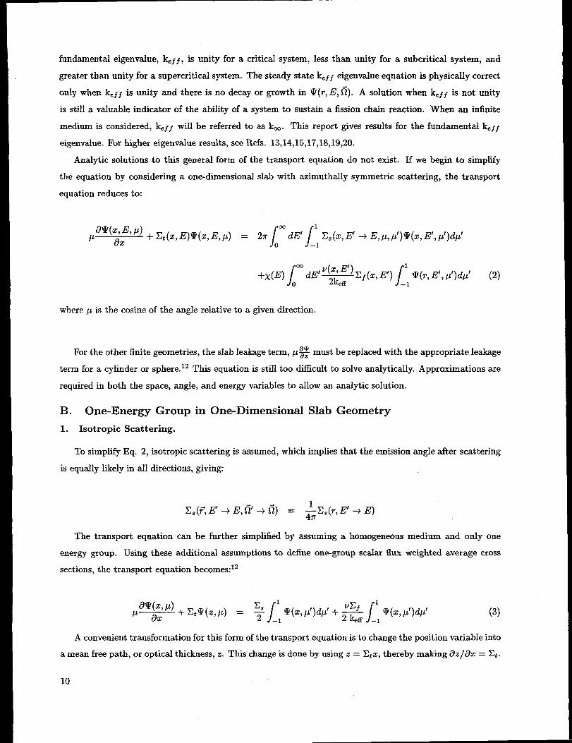
fundamental eigenvalue, k.f ~, is unity for a critical system, less than unity for a subcritical system, and
greater than unity for a supercritica.1 system. The steady state k.ff eigenvalue equation is physically correct
only when k. ~~ is unity and there is no decay or growth in !2(r, E, @. A solution when lQf ~ is not unity
is still a valuable indicator of the ability of a system to sustain a fission chain reaction. VVhen an infinite
medium is considered, ke~~ will be referred to as km. Thk report gives results for the fundamental &f ~
eigenvalue. For higher eigenvalue results, see Refs. 13,14,15,17,18,19,20.
Analytic solutions to this general form of the transport equation do not exist. If we begin to simplii
the equation by considering a one-dimensional slab with azimuthally symmetric scattering, the transport
equation reduces to:
18Q(% ~J P) + ~t(z, E)v(z, 1?, P) = 2K
P ax 1“ /dE’ ~~(z, E’ + E, /J,P’)IV(Z, E’, p’)dp’
–1
S/
co 1dE/ ‘(X7 “) ~f(~, E’)
+x(E) 2k.ff JV(T7E’, p’)dp’ (2)
o –1
where p is the cosine of the angle relative to a given direction.
For the other finite geometries, the slab leakage term, p% must be replaced with the appropriate leakage
term for a cylinder or sphere. 12 This equation is still too difficult to solve analytically. Approximations are
required in both the space, angle, and energy variables to allow an analytic solution.
B. One-Energy Group in One-Dimensional Slab Geometry
1. Isotropic Scattering.
To simplify Eq. 2, isotropic scattering is assumed, which implies that the emission angle after scattering
is equally likely in all directions, giving:
The transport equation can be further simplified by assuming a homogeneous medkm and only one
energy group. Using these additional assumptions to define one-group scalar flux weighted average cross
sections, the transport equation becomes:12
(3)
A convenient transformation for this form of the transport equation is to change the position variable into
a mean free path, or optical thickness, z. This change is done by using z = Ztx, thereby making i3z/i7x = Xt.
10

If we divide the transport equation by &, and use the change of variables, the neutron transport equation
becomes:
()/.4 m-qz, /4) 8Z z,+% 1
z az7& +lqz, p) = e
/2zt _~V(Z> p’)dp’ (4)
Notice that the dimensionless position variable, z, is now defined in terms of mean free paths (mfp) (i.e.,
I/Zt). The final simplified one-energy group transport equation for a slab can be written in a slightly more
convenient form as:
where:
(5)
(6)
The parameter c is defined as the mean number of secondary neutrons produced per neutron reaction
and is also known as the secondaries ratio. This equation is the form of the one-medium, one-energy group
transport equation for a slab. This equation still requires elaborate mathematics to solve as reported in the
literature. Derivation of the one-energy group km solution for the infinite medium case is shown in Appendix
A. A c of unity is equivalent to a km of unity. Thus, c must be greater than unity to have a finite critical
system.
The literature uses this form of the neutron transport equation with a non-reentrant boundary condition
to derive one-energy group, isotropic scattering analytic solutions for the critical (k.f ~=1) dimensional scalar
neutron flux. It should be noted that c values for keff = 1 in Eq. 6 are presented in the literature, thereby
‘s+v~f The typical range of c found in the literature for fissile materials is from 1.01 to 2.00.making c = ~.
The one-group cross sections selected for the test set mimic the physical characteristics of the two-group
problems and range from 1.02 to 1.50. A value of c of 1.5 is the upper limit for real fissile materials.
2. Linearly Ani.sotropic Scattering.
The scattering term, ES(F, E’ + E, 6’ + 6) can be a strong function of the cosine of the scattering
angle, PO = !?l’ . h, The angular dependence can be analyzed by Legendre polynomial series expansion of
Z. (?, E’ + E,& . H) .21 Using the Legendre polynomial expansion, the one-energy group, one-dimensional
slab, neutron transport equation can be written in a similar form to Eq. 5:22’23
Solutions for this form of the neutron transport equation are often found in the literature. The solution of
this equation includes linearly anisotropic scattering however, it also includes a linearly anisotropic fission
11

source emission. For problems that include the anisotropic effect on the fission term, see Refs. 15,22,23.
Solutions for the higher eigenvalues exist for this form of the transport equation.13~14~15~17~ls*lg’20
Numerical solutions exist that do not force the anisotropic effect on the fission term. This limitation
on the different anisotropic behavior of scattering and fission can be removed by using diilerent transfer
functions for scattering and fission. The neutron transport equation can be written as:24
(7)
where:
II(po, p) = /31-I,(po) i- (1 – @)IIf(po)
The parameters, Ifs (PO) and IIf (PO), are the angular transfer functions for scattering and fission, re-
spectively, and are dependent on p and p’. The weighting parameter, @, allows for the different anisotropic
behavior for the scattering and fission terms. This is one of several ways found in the references of separating
the anisotropic scattering and fission terms.
C. Two-Energy Groups in One-Dimensional Slab Geometry
1. Isotropic Scattering.
Using the same procedures as in the one-group case, the two-energy group form of the transport equation
for a slab can be written ass
where:
Z~ = total neutron macroscopic cross section of group i
~~~ = total neutron group transfer macroscopic cross section
from group j to group i
In this report, the fast energy group is group 2 to be consistent with most of the references.
This notation is the reverse of most nuclear engineering textbooks.
Assuming group 2 is the fast group and no non fission up-scatter for the slow group 1, the group transfer
cross sections are given by:
12
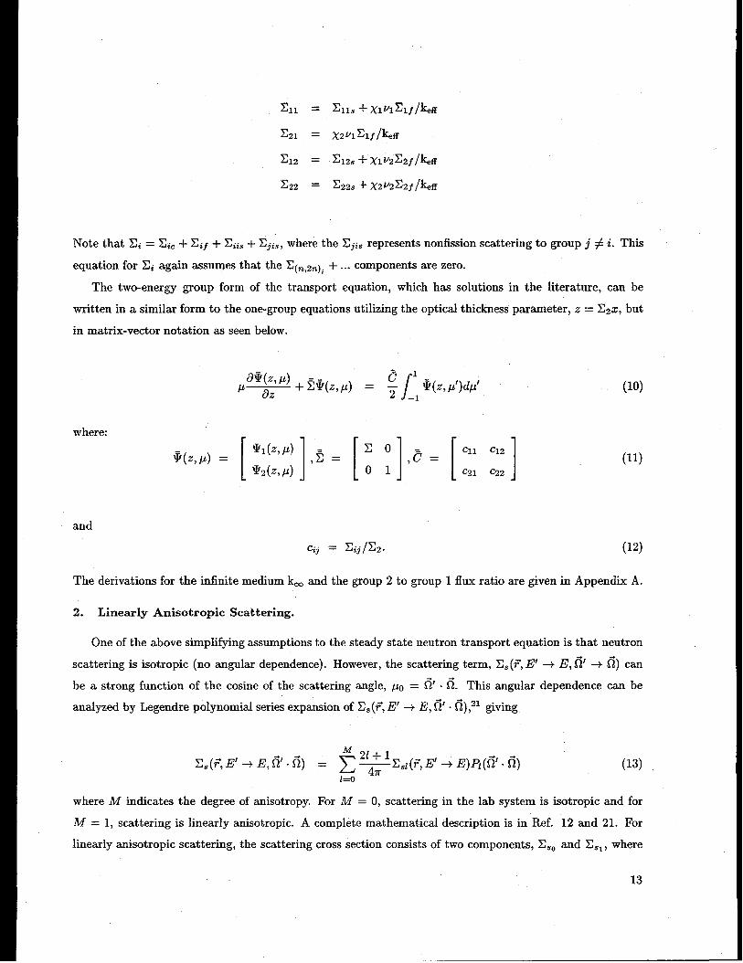
Note that Ili = ~ic + Z~f + Xais+ Zjis, where the .Xji$ represents nonfission scattering to group j #i. This
equation for xi again assumes that the Z(n,2.)i +... components are zero.
The two-energy group form of the transport equation, which has solutions in the literature, can be
written in a similar form to the one-group equations utilizing the optical thickness parameter, z = X2X, but
in matrix-vector notation as seen below.
where:
(lo)
(11)
and
C~j = Eij/E2. (12)
The derivations for the infinite medium km and the group 2 to group 1 flux ratio are given in Appendix A.
2. Linearly Anisotropic Scattering.
One of the above simplifying assumptions to the steady state neutron transport equation is that neutron
scattering is isotropic (no angular dependence). However, the scattering term, Xs (F, 1?’ + E,& + h) can
be a strong function of the cosine of the scattering angle, p. = @ .6. Thk angular dependence can be
analyzed by Legendre polynomial series expansion of Z, (7, E’ + E, S%. 6),21 giving
M 21+1X,(F, E’ + E,fi’ - d) = ~ —E~l(F, E’ + E) F@’ . fi)
1=0 4X(13)
where M indicates the degree of anisotropy. For M = O, scattering in the lab system is isotropic and for
M = 1, scattering is linearly anisotropic. A complete mathematical description is in Ref. 12 and 21. For
linearly anisotropic scattering, the scattering cross section consists of two components, E,O and Z,l, where
13

Zs, is the linear anisotropic scattering component and ailects the scattering angular distribution for both in
and out of group scattering. Anisotropic scattering can be forward or backwaxd peaked and thus Z$l can be
positive or negative. For linear anisotropic scattering in the one-energy group case, Z,(p) = (2,0 +3@~l )/2.
Thus, E.(p) can become negative when IZ,, I > E,, /3. Test set problems 34, 37, 43, and 71 efilbit this
behavior. The total scattering cross section is not dependent on Ilsl. The anisotropic cross section only allects
the angular distribution. Infinite medium km and neutron flux results are independent of the anisotropic
cross section.
Using the Legendre polynomial expansion, the neutron transport equation for a one-dimensional slab
with azimuthally symmetric scattering can be written in a form similar to Eq. 2:
6W(Z, E, p)+ E~(z, E)14?(z, E, p) = 27r~“dE’g
M 21+1P —E.i(E’ + E)H(P) /1 H(P’)Q(z, p’)dp’
ax 47r –1
r V(Z>E’) ~f(z, ~,,
/
1+x(E) dE’
2k,ff~(r, E’, /J)dp’ (14)
o –1
Following the same procedures as in Eq. 5, the general two-speed linearly anisotropically scattering
analogue to Eq. 10 which also has numerical solutions is:25
a!l(z, p)
p i3z+ 5=(2, p) = :~@113(#)
1=0
where:
and
/ –1
[
Clll Clzl,Cl =
cz~l C221
(15)
(16)
(17)
The Zijs, term is the linearly anisotropic scattering cross section and is given in the problem descriptions
without the (21 + 1) term.
14

VI. ONE-ENERGY GROUP PROBLEM DEFINITIONS
AND RESULTS
For the one-energy group cases, the critical dimension(s) for each geometry depends upon the c value
chosen from the literature and not specific cross-section sets. To use the literature results, the cross sections
were selected to match published c values with k, f f =1 at low, middle, and high c values listed. Values ranging
from 1.02, 1.30, 1.40, and 1.50 were chosen because they are similar to the physical systems in the two-group
cases: uranium-DzO reactor, U-235, and Pu-239. These problems use cross sections that are reasonable
representations of these materials; however, these cross sections are not general purpose one-group values.
The cross sections are used because they define the c values used in the literature and are intended to be
used only to verify aJgorithm performance and not to predict any actual criticality experiments.
The isotropic neutron macroscopic cross sections provided for each case are: the total cross section,
Zt, the capture (no neutrons emitted) cross section, Z., the scattering cross section, 2$, the fission cross
section, Zf, and the number of neutrons, v, emitted for each fission. The (n,2n), (n,3n), ... cross sections
are assumed to be zero (but need not be). Thus the total cross section equals the sum of &j ES, and Z ~,
thereby providing a consistency check on the cross-section set. Many references give (vZ f ) instead of v
and Z f. Since both parameters (not the product) may be required by a code for the problem solution, the
product (vIlf) has been split into v and Ef preserving their product and Z~. The value of c for k. f $=1 in
Eq. 6 is also included in each cross-section table. For the reflected spheres, different secondaries ratios, c, are
reported with the critical dimension for kef f =1 for various combinations of core and reflector thicknesses.
To maintain consistent cross sections with the U-235 set, the parameter, v, was modified to match c to the
literature values.
When anisotropic scattering cross sections are provided, the anisotropic components are designated by
Esl and E$z, respectively. Similarly, the isotropic scattering component is designated by ,Z~O.
The value of km, as defined in Appendix A, is given for each cross-section set. For finite problems where
k.f f is unity, the critical dimension, r., is listed for each geometry in both mean free paths (to indicate the
neutron optical thi&ness) and in centimeters for the one-dimensional geometries. When available in the
literature, the scalar flux values, normalized to the flux at the center of the fissile material, are also provided.
The two-media problems have c1 >1 for the core region 1 and cz”< 1 for the surrounding reflector region 2.
The two-media problems use the cross sections for the nonmultiplying reflector, The critical dimensions for
the multiplying medhun and reflector thickness are given in both mean free paths and centimeters.
A comparison of the critical dimensions for the diilerent geometries behave as expected; that is, the
critical dimension is smallest for the one-dimensional slab and increases for the cylinder and sphere. This
behavior is to be expected due to the increased leakage with the curvi-linear geometries. For the reflected
geometries, the critical dimension decreases with increasing reflector thickness.
15

A. One-Energy Group Isotropic Scattering
1. One-Group Pu-239.
One-Energy Group Isotropic Cross Sections
Table 5 gives the one-group, isotropic cross sections for two case of Pu-239 (c=l.50 and c=l.40) and a
HzO (c=O.90) reflector. The total cross sections are the same for both Pu-239 cases and H20 as required by
the reference for the two-media solutions.
Table 5: One-Group Macroscopic Cross Sections (cm-l) for Pu-239 (c=l.40,1.50) and H20 (c=O.90)
Material I v Xf & x, I .ztlc
Pu-239 (a) [ 3.24 I 0.081600 [ 0.019584 I 0.225216 I 0.32640 [ 1.50Pu-239 (b) 2.84 0.081600 0.019584 0.225216 0.32640 1.40H20 (refl) 0.0 0.0 0.032640 0.293760 0.32640 0.90
Infinite Medium (PUa-1-O-IN and PUb-1-O-IN)
Using the cross sections for Pu-239 (a) (problem 1) in Table 5, km = 2.612903 with a constant angular
and scalar flux everywhere. Using the cross sections for Pu-239 (b) (problem 5) in Table 5, km = 2.290323
with a constant angular and scalar flux everywhere.
One-Medium Slab, Cylinder, and Sphere Critical Dimensions
The Pu-239 (a) critical dimension, r., is listed in Table 6.
Table 6: Critical Dimensions, rC, for One-Group Bare Pu-239 (c=l.50)
Problem I Identifier I Geometry \ r. (mfp) r= (cm) ] Reference2 I PUa-1-O-SL Slab { 0.605055 I 1.853722 I 9
The Pu-239 (b) critical dimensions, r., are listed in Table 7. The normalized scalar flux for four spatial
positions are given in Table 8 using the same references. The flux ratios for PUb-1-O-CY are only available
to four decimal places.
Table 7: Critical Dimensions, r., for One-Group Bare Pu-239 (c=l.40)
Problem Identifier Geometry r. (mfp) rC (cm) Reference6 PUb-1-O-SL Slab 0.73660355 2.256751 267 PUb-1-O-CY Cylinder 1.396979 4.279960 27,288 Pub-1-o-sP Sphere 1.9853434324 6.082547 26
Table 8: Normalized Scalar Fluxes for One-Group Bare Pu-239 (c=l.40)
Problem Identifier6 PUb-1-O-SL7 PUb-1-O-CY8 PUb-1-O-SP
Geometry r/rC = 0.25 r/rC = 0.5 r/rC = 0.75 r/rC = 1.0Slab 0.9701734 0.8810540 0.7318131 0.4902592
Cylinder — 0.8093 — 0.2926Sphere 0.93538006 0.75575352 0.49884364 0.19222603
16

Two-Media Slab and Cylinder Critical Dimensions
The literature values in Tables 9 and 10, give the critical dimensions for Pu-239 (a) for two H2O reflector
thicknesses. The first two-media problem (problem 3) in Table 9 is a special nonsymmetric two-region, Pu-
239 and H20, problem. The second two-media problem (problem 4) in Table 10 is a symmetric three-region
problem with the reflector on both sides of the fissile medium.
Table 9: Critical Dimensions for One-Group Pu-239 Slab (c=l.50) with Non-Symmetric H20 Reflector(C=O.90)
Problem Identifier Geometry Pu r. HzO thickness Pu+HzO Radhs Reference3 PUa-H20(l)-1-O-SL Slab (mfp) 0.48255 1 9
(cm) 1.478401 3.063725 4.542126
Table 10: Critical Dimensions for One-Group Pu-239 Slab (c=l.50) with H20 Reflector (c=O.90)
Problem Identifier Geometry Pu r= HzO thickness Pu+HzO radius Reference4 PUa-H20(0.5)-l-O-SL Slab (mfp) 0.43014 0.5 9
(cm) 1.317831 1.531863 2.849694
The literature
thicknesses.
values in Table 11, give the critical dimensions for Pu-239 (b) with two H2O reffector
Table 11: Critical Dimensions for One-Group Pu-239 Cylinder (c=l.40) with H20 Reflector (c=O.90)
Problem Identifier Geometry Pu r= HzO thickness Pu+HzO Ri3dlUS Reference9 PUb-H20(l)-l-O-CY Cylinder (mfp) 1.10898 1 29
(cm) 3.397610 3.063725 6.46133510 PUb-H20(10)-l-O-CY Cylinder (mfp) 1.00452 10 29
(cm) 3.077574 30.637255 33.714829
17

2. One-Group U-235.
One-Group Isotropic Cross Sections
Table 12 gives the one-group, isotropic cross sections for two cases of U-235 and a H2O reflector. Notice
that one-group ~t for Pu-239 and U-235 are the same as given in reference 32, but the secondaries ratio, c,
differs.
Table 12: One-Group Macroscopic Cross Sections (cm-l) for U-235 (c=l.30)
MaterialU-235 (a)U-235 (b)U-235 (C)
U-235 (d)H20 (refl)
v
2.702.7971012.7073082.679198
0.0
Zf
0.0652800.0652800.0652800.065280
0.0m0.032640 I 0.293760 ] 0.32640 3
c
1.301.31942021.30146161.2958396
0.90
Infinite Medium (Us-l-O-IN , Ub-1-O-IN , UC-1-O-IN , and Ud-1-O-IN )
Using the cross sections for U-235 (a) in Table 12, km = 2.25 (problem 11) with a constant angular and
scalar flux everywhere. Using the cross sections for U-235 (b), U-235 (c), and U-235 (d) in Table 12, km
= 2.330917 (problem 15), 2.256083 (problem 17), and 2.232667 (problem 19) with a constant angular and
scalar flux everywhere, respectively.
One-Medium Slab, Cylinder, and Sphere Critical Dimensions
The critical dimension, r., and spatial flux ratios are given in Table 13 and 14 for U-235 (a). The
references are the same for both tables.
Table 13: Critical Dimensions, r=, for One-Group Bare U-235 (c=l.30)
Problem Identifier Geometry rc (mfp) r= (cm) Reference12 Ua-1-O-SL Slab 0.93772556 2.872934 2613 Ua-1-O-CY Cylinder 1.72500292 5.284935 27,2814 Ua-1-O-SP Sphere 2.4248249802 7.428998 26
Table 14: Normalized Scalar Fluxes for One-Group Bare U-235 (c=l.30)
Problem I Identifier Geometry r/rC = 0.25 I r/rC = 0.5 I r/rC = 0.75 r/rC = 1.012 I Ua-1-O-SL I Slab I 0.9669506 0.8686259 0.7055218 0.4461912
I 14 I Ua-1-O-SP ] S~here ] 0.93244907 I 0.74553332 I 0.48095413 I 0.17177706 ]
18

Two-Media Sphere Critical Dimensions
The literature values in Table 15, give the critical dimensions for U-235 (b), U-235 (c), and U-235 (d) for
three spherical H2O reflector thicknesses.
Table 15: Critical Dimensions for One-Group U-235 Sphere with H20 Reflector (c=O.90)
Problem Identifier Geometry U r.16 Ub-H20(l)-l-O-SP Sphere (mfp) 2
(cm) 6.1274518 UC-H20(2)-1-O-SP Sphere (mfp) 2
(cm) 6.1274520 Ud-H20(3)-l-O-SP Sphere (mfp) 2
(cm) 6.12745
H~O thickness
3.0637252
6.127453
9.191176
U+H20 R,adlUS Reference17,20
9.19117617,20
12.254917,20
15.318626
19

3. One-Group U-DZO Reactor.
One-Group Isotropic Cross Sections
Table 16 gives the on~group, isotropic cross sections for the uranium-DzO reactor and H20 reflector.
Note that the uranium-D20 reactor and H20 reflector have the same total cross section aa required by the
references for the reflected cylindrical solutions.
Table 16: One-Group Macroscopic Cross Sections (cm-l) for U-D20 Reactor (c=l.02) and H20 (c=O.90)
~
Infinite Medium RJD20-1-O-IN)
Using the cross sections for U-DZO in Table 16, km = 1.133333 (problem 21) with a constant angular
and scalar flux everywhere.
One-Medium Slab. CvIinder, and Sphere Critical Dimensions
The critical dimension, r., and spatial flux ratios are listed in Table 17 and 18.
Table 17 Critical Dimensions, r=, for One-Group Bare U-DZO Reactor (c=l.02)
Problem Identifier Geometry r. (mfp) rc (cm) Reference22 UD20-1-O-SL Slab 5.6655054562 10.371065 2623 UD20-1-O-CY Cylinder 9.043255 16.554249 27,2824 UD20-1-O-SP Sphere 12.0275320980 22.017156 26
Table 18: Normalized Scalar Fluxes for One-Group Bare U-DZO Reactor (c=l.02)
Problem Identifier Geometry r/rC = 0.25 r/rC = 0.5
22 UD20-1-O-SL Slab 0.93945236 0.7650408424 UD20-1-O-SP Sphere 0.91063756 0.67099621
Two-Media Slabs and Cylinders Critical Dimensions
Table 19 gives the U-D20 critical dimension, r,, for two H20 reflector thicknesses.
Table 19: Critical Dimensions for One-Group U-DZO (c=l.02) Slab and Cylinder with HzO (c=O.90) Re-flector
26
27
28
20
IdentifierUD20-H20(1)-1-O-SL
UD2O-H2O(1O)-1-O-SL
UD20-H20(1)-1-O-CY
UD2O-H2O(1O)-1-O-CY
GeometrySlab (mfp)
(cm)Slab (mfp)
(cm)Cylinder (mfp)
(cm)Cylinder (mfp)
(cm)
UDZO r, I HzO thickness \ UDZO + HzO radius5.0335 1
9.2141394.6041
8.4280968.41102715.3969167.97932514.606658
1.83056310
18.305631
1.830563 ~10
18.30563
11.044702
26.733726
17.227479
32.912288
Reference33,34
33,34
29
29

4. One-Group U-235 Reactor.
One-Group Isotropic Cross Sections
Table 20 gives the one-group, isotropic cross sections for the U-235 reactor with a Fe reflector and Na
moderator.
Table 20: One-Group Macroscopic Cross Sections (cm–l ) for U-235 Reactor, Fe reflector, and Na Moderator
Material v Zf xc & Zt cU-235 (e) 2.50 0.06922744 0.01013756 0.328042 0.407407 1.230Fe (refl) 0.0 0.0 0.00046512 0.23209488 0.23256 0.9980
Na (mod) 0.0 0.0 0.0 0.086368032 0.086368032 1.00
Infinite Medium (Ue-1-O-IN)
Using the cross sections for the U-235 reactor in Table 20, km = 2.1806667 (problem 29) with a constant
angular and scalar flux everywhere. ”
One-Medium Slab Critical Dimensions
Note that this problem is a nonsymmetric four-region problem. The U-235 is surrounded by a Fe cladding
on two sides but moderated by Na on one side. The critical dimension, re, is listed in Tables 21 and 22.
Table 21: Critical Dimensions, r., for One-Group U-235 Reactor
Problem Identifier Geometry Fe thickness U-235 thickness Fe thickness Na t~lckness Reference30 Ue-Fe-Na-l-O-SL Slab (mfp) 0.0738 2.0858098 0.0738 0.173 45
(cm) 0.317337461 5.119720083 0.317337461 2.002771002
Table 22: Critical Dimensions, rc, for One-Group U-235 Reactor
Problem \ Identifier \ Geometry Fe thickness Fe+U Fe+U+Fe Fe+U+Fe+Na30 I Ue-Fe-Na-l-O-SL [ Slab (cm) 0.317337461 5.437057544 / 5.754395005 7.757166007
The U-235 (e) critical dimensions, r., are listed in Tables 21 and 22. The normalized scalar flux for four
spatial positions are given in Table 23 using the same references. These positions correspond to the material
boundaries and are normalized by the scalar neutron flux at the left boundary.
Table 23: NormJlzed Scalar Fluxes for One-Group U-235 Reactor
Problem \ Identifier I Geometry I Fe-U U-Fe Fe-Na I Na30 I Ue-Fe-Na-l-O-SL \ Slab I 1.229538 I 1.49712 I 1.324899 I 0.912273
21

B. One-Group Anisotropic Scattering
1. One-Group Pu-239.
One-Energy Group Anisotropic Cross Sections
Table 24 gives the one-group, anisotropic cross sections for two cases of anisotropic scattering. The first
cross-section set, Pu-239 (a), includes PI and Pz scattering cross sections, where I p I< 1/3. The second
cross-section set, Pu-239 (b), includes the P1 and Pz scattering cross sections where I p I> 1/3. Care must
be used to correctly solve benchmark problem 34 because of the negative scattering for p near
-1.
Table 24: One-Group Macroscopic Anisotropic Cross Sections (cm-l) for Pu-239 (c=l.40)
Material v Xf .XC X.. x E Et c
Pu-239 (a) 2.5 0.266667 0.0 0.733333 0.;0 0.:;5 1.0 1.40Pu-239 (b) 2.5 0.266667 0.0 0.733333 0.333333 0.125 1.0 1.40
Infinite Medium (PU-1-1-IN]
Using the cross sections for Pu-239 (a) and Pu-239 (b) in Table 24, km = 2.5 (problem 31) with a constant
angular and scalar flux everywhere. The anisotropic scattering cross sections do not change km.
One-Medium Slab Critical Dimensions
The Pu-239 critical dimensions, rc, for both P1 and Pz problems are listed in Table 25.
Table 25: Critical Dimensions, rc, for One-Group Bare Pu-239 (c=l.40)
Problem I Identifier I Geometry \ rC (mfp)32 I PUa-1-l-SL Slab 0.7703233 PUa-1-2-SL Slab 0.7637834 PUb-1-l-SL Slab 0.7960635 I PUb-1-2-SL 1. Slab I 0.78396
0.76378 300.79606 30 I0.78396 I 30
22

2. One-Group U-235
One-Enerzv GrouD AnisotroDic Cross Sections
Table 26 gives the two sets of one-group, anisotropic cross sections for U-235.
sections are the same as in Table 12 with the addition of PI scattering cross sections.
Notice that the cross
The first cross-section
set, U-235 (a), includes PI scattering cross sections, where I p I< 1/3. The second cross-section set, U-235
(b), includes the P1 scattering cross sections where I p ]> 1/3. Care must be used to correctly solve
benchmark problem 37 because of the negative scattering for p near -1.
Table 26: One-Group Macroscopic Anisotropic Cross Sections (cm-l) for U-235 (c=l.30)
Material u -Xf .XC E x., Et
U-235 (a) 2.70 0.065280 0.013056 0.24~064 0.042432 0.32640 1:0U-235 (b) 2.70 0.065280 0.013056 0.248064 0.212160 0.32640 1.30
Infinite Medium (U-1-1-IN)
Using the cross sections for U-235 (a) and U-235 (b) in Table 26, km = 2.25 (problem 11) with a constant
angular and scalar flux everywhere. The anisotropic scattering cross sections do not change km.
One-Medium Slab Critical Dimensions
The U-235 critical dimensions, rC, for both PI problems are listed in Table 27.
Table 27: Critical Dimensions, r., for One-Group Bare U-235 (c=l.30)
Problem Identifier Geometry r. (mfp) rC (cm) Reference
36 Ua-1-l-CY Cylinder 1.799866479 5.514296811 3137 Ub-1-l-CY Cylinder 2.265283130 6.940205668 31
23

3. One-Group U-D20
One-Energy Group Anisotropic Cross Sections
Table 28 gives the two sets of one-group, anisotropic cross sections for U-D20 reactor. Notice that the
cross sections are the same as in Table 16 with the addition of PI scattering cross sections. The cross-ections
set for two U-D2 O cases include PI scattering cross sections, where I p I< 1/3, and a PI case where p <0 and
the scattering cross section is negative. Care must be used to correctly solve benchmark problem
43 because of the negative scattering for p near 1.
Table 28: One-Group Macroscopic Anisotropic Cross Sections (cm–l) for U-DZO Reactor
Material .Xf E. z x Xt
U-DZO (a) 1.80~381 0.054628 0.027314 0.46;338 0.056:;2624 0.54628 1.03;8381U-D20 (b) 1.841086 0.054628 0.027314 0.464338 0.112982569 0.54628 1.0341086U-D20 (C) 1.6964 0.054628 0.027314 0.464338 -0.27850447 0.54628 1.01964
Infinite Medium UD20a-1-l-IN , UD20b-1-l-IN , and UD20C-1-1-IN
Using the cross sections for U-DZO (a), U-DZO (b), and U-D20 (c) in Table 28, km = 1.205587 (problem
38), 1.227391 (problem 40), and 1.130933 (problem 42), respectively, with a constant angular and scalar flux
everywhere. The anisotropic scattering cross sections do not change km.
One-Medium Slab Critical Dimensions
The U-DZ O critical dimensions, rc, for the PI problems are listed in Table 29.
Table 29: Critical Dimensions, rc, for One-Group Bare U-DZO
Problem394143
Identifier Geometry rC (mfp) rC (cm) ReferenceUD20a-1-l-SP Sphere 10 18.30563081 15UD20b-1-l-SP Sphere 10 18.30563081 15UD20C-1-1-SP S~here 10 18.30563081 16
24

VII. TWO-ENERGY GROUP PROBLEM
AND RESULTS
DEFINITIONS
The isotropic two-energy group cross sections for five bare and two water reflected cases are listed in this
section. There are also two linearly anisotropic scattering cross-sections sets provided for bare and infinite
medium reactors. Unlike the one-group case, there is no flexibility in choosing these values since they are used
throughout the literature. The cross sections listed here are similar to PU-239,32 U-235,32 a realistic enriched
uranium-aluminum-water assembly,s a 93% enriched U-235 model of a university research reactor,8’35’36 and
a typical large size D2O reactor with low enrichment of U-235 .S’35’36Also included are critical dimensions
for a similar uranium research reactor with a water reflector in an infinite lattice. 34 Again, these problems
use cross sections that are reasonable representations of the materials described. These cross sections are
not general purpose two-group values. The cross sections are used because they are defined in the literature
and are intended to be used only to verify algorithm performance and not to predict any actual criticality
experiments.
The isotropic neutron cross macroscopic sections (cm–l ) provided for these problems are the total cross
section of group i, ZZ, the capture (no neutrons emitted) cross section, ~Ci, the within group scattering cross
section, ~ii~, the group-to-group scattering cross sections, ~ij~ and ~j~~, the fission cross section, ~if, the
number of neutrons, vi, emitted from each fission in a group, and the fission distribution, Xi.
In this report, the fast energy group is group 2 to be consistent with most of the references.
This notation is the reverse of most nuclear engineering textbooks.
The literature solutions are often bssed on the group transfer cross sections, Xij, given in the references;
therefore, the individual cross sections may not be unique. Most references give (vZ f )i instead of vi and Xfi.
Since both parameters (not the product) may be required by a code for the problem solution, the product
(v.Ef )i has been split into vi and Zf ~preserving their product and Zt. The infinite slab lattice problems use
a slightly unphysical set of cross sections to possibly stress code verification.
The two sets of linearly anisotropic cross sections provided are extensions of the university research
reactor and D20 cases.25 The anisotropic scattering component is designated for the in-group and group-to-
group scattering cross section by Zii~l and ~ji.ql, respectively. Similarly, the isotropic scattering component
is designated by Xii~Oand ZjiSO.
The value for km is given for each cross-section set. The in-group scattering cross sections do not affect
km. For finite problems, the critical dimension, r=, is listed in both fast group mean free paths (to indicate
the neutron optical thickness) and in centimeters. For two-media problems, critical dimensions for the inner
multiplying medium and outer reflector thickness are given in both fast mean free paths and centimeters.
The critical dimensions, r., and reflector half thicknesses are also given for a water reflected infinite slab
25

lattice cell. Flux values are given for the university research reactor (a) (problems 54 and 71) at four spatial
points. Angular fluxes can be found in the dissertation references.
To distinguish between the different URR fissile material cross-section sets, each is labeled with a letter
“a,” “b,” “c,” or “d”, respectively. The infinite slab lattice cell cross sections are simh- to the other three
cross-section sets for the university research reactor and are labeled with URRd identifiers. The literature
also uses three different HzO reflectors. Their cross sections are also labeled with a letter “a,” “b,” or “c”
in the identifier. URR cross-section sets “b” and “c” have thermal upscattering. All other two-group cross
sections have no thermal upscattering.
A comparison of the critical dimensions for the different geometries behave as expected; that is, the critical
dimension is smallest for the one-dimensional slab and increases for the cylinder and sphere. This behavior is
to be expected due to the increased leakage with the curvi-linear geometries. The effect of increased leakage
on the critical dimension can be also be seen for the forward peaked linear anisotropically scattering cases.
For the reflected geometries, the critical dimension decreases with increasing reflector thickness. However,
the critical dimension for the infinite lattice cell increases with the increasing moderator thickness. Even
though this may seem counter-intuitive, it should be expected because the amount of interaction between
the fissile medium and adjacent cells decreases with increasing moderator half thickness.34
26

A. Isotropic Scattering
1. Two-Group Pu-239.
Two-Group Isotropic Cross Sections
Tables 30 and 31 give the two-group, isotropic cross sections for Pu-239.
Table 30: Fast Energy Group Macroscopic Cross Sections (cm–~) for Pu-239
r Material V2. I E2f I 22. I X22* I 212,] X2 Ir
Pu-239 3.10 I 0.0936 I 0.00480 I 0.0792 I 0.0432 ] 0.2208 I 0.?75
Table 31: Slow Energy Group Macroscopic Cross Sections (cm-l ) for Pu-239
Material VI I Xlf 21. Z1l. I X21. xl IPu-239 2.93 [ 0.08544 I 0.0144 0.23616 I 0.0 0.3360 I 0.?25
Infinite Medium (PU-2-O-IN)
Using the two-group isotropic Pu-239 cross-section
44) with a constant group angular and scalar flux and
set from Tables 30 and 31, km = 2.683767 (problem
a group 2 to group 1 flux ratio = 0.675229.
One-Medium Slab and Sphere Critical Dimensions
The critical dimensions, rC, are listed in Table 32.
Table 32: Critical Dimensions, rc, for Two-Group Bare Pu-239
Problem I Identifier I Geometry [ r= (mfp) r. (cm) I Reference45 I PU-2-O-SL I Slab I 0.396469 ~ 1.795602 I 8,35,36
I 46 I PU-2-O-SP I %here I 1.15513 I 5.231567 I 8 I
27

2. Two-Group U-235.
Two-Group Cross Sections
Tables 33 and 34 give the two-group, isotropic cross sections for U-235.
Table 33: Fast Energy Group Macroscopic Cross Sections (cm-l) for U-235
Material [ V2 Zzf 22. 222$ I X12.I X2 \ X.2U-235 ! 2.70 i 0.06192 I 0.00384 I 0.078240 I 0.0720 I 0.2160 I 0.575
Table 34: Slow Energy Group Macroscopic Cross Sections (cm–l) for U-235
Material I VI I Zlf Xlc ‘X11. I 221. [ xl
U-235 I 2.50 I 0.06912 I 0.01344 ! 0.26304 \ 0.0 ! 0.3456 I 0?25
Infinite Medium (U-2-O-IN)
cross-section set from Tables 33 and 34, km = 2.216349 (problem 47) with aUsing the two-group U-235
constant group angular and scalar flux and the group 2 to group 1 flux ratio = 0.474967
One-Medium Slab and SDhere Critical Dimensions
The criticzd dimensions, rC, are listed in Table 35.
Table 35: Critical Dimension, rc, for Two-Group Bare U-235
Problem ] Identifier \ Geometry I r. (mfp) rC (cm) I Reference48 ] U-2-O-SL Slab I 0.649377 I 3.0063751 8,35,36
\ 49 I U-2-O-SP I Sphere I 1.70844 I 7.909444 I 8’ I
28

3. Two-Group Uranium-Aluminum-Water Assembly.
Two-GrouD Isotronic Cross Sections
Tables 36 and37 gives the two-group, isotropic cross sections for the uranium, aluminum, and water
assembly.
Table 36: Fast Energy Group Macroscopic Cross Sections(cm-l) for U-Al
Material I V2 I Xzf / 22. .&z. I ‘812, I &U-Al I 0.0 I 0.0 { 0.000222 I 0.247516 I 0.020432 I 0.26817 I ?0
Table 37: Slow Energy Group Macroscopic Cross Sections (cm-l) for U-Al
Material VI Xlf Xlc X11. 221s \ a IU-Al 2.83 I 0.06070636042 0.00314363958 1.21313 0.0 I 1.27698 I ;;
Infinite Medium (UAL-2-O-IN)
With the two-group cross-section set from Tables 36 and 37, km = 2.661745 (problem 50) and the group
2 to group 1 flux ratio = 3.1250.
One-Medium Slab and SDhere Critical Dimensions
Using the cross sections given in Tables 36 and 37, the critical dimensions, rc, are given in Table 38.
Table 38: Critical Dimensions, r., for Two-Group Uranium-Aluminum-Water Assembly
Problem I Identifier Geometry I r. (mfp) I r. (cm) ] Reference51 I UAL-2-O-SL I Slab 2.09994 \ 7.830630 I 8,35,36
I 52 \ UAL-2-O-SP I %here I 4.73786 \ 17.66738 I 8’ I
29

4. Two-Group Uranium Research Reactor.
Two-GrouD Isotro~ic Cross Sections
The cross sections for the one-medhun (a), two-media (b and c), and infinite slab lattice (d) cases are
different and are therefore listed separately. Tables 39 and 40 gives the two-group, one-medium, isotropic
cross sections for the 9370 enriched uranium bare university research reactor.
Table 39: Fast Energy Group Macroscopic Cross Sections (cm-l ) for Research Reactor (a)
Material I I ‘zZf X2= Xzz. X12, ,XZ IResearch Reactor [a) I 2%0 I 0.0010484 I 0.0010046 I 0.62568 \ 0.029227 I 0.65696 [ ?:
Table 40: Slow Energy Group Macroscopic Cross Sections (cm-l ) for Research Reactor (a)
Material I Z/l I Elf Xlc 211. 221$ I 21
Research Reactor (a) I 2.50 I 0.050632 I 0.025788 I 2.44383 I 0.0 I 2.52025 I &
Infinite Medium (URRa-2-O-IN)
The test set uses the two-group enriched U-235 cross-section set for the research reactor in Tables 39 and
40 with km = 1.631452 (problem 53) and the group 2 to group 1 flux ratio = 2.614706.
One-Medium Slab and %here Critical Dimensions
The critical dimensions, rC, are listed in Table 41.
Table 41: Critical Dimensions, rc, for Two-Group Bare Research Reactor (a)
Problem Identifier Geometry r= (mfp) rC (cm) Reference54 uRRa-2-o-sL Slab 4.97112 7.566853 8,35,3655 URRa-2-O-SP Sphere 10.5441 16.049836 8
One-Medium SIab Scalar Neutron Fluxes
Table 42 gives the normalized scalar neutron flux for the two-group bare research reactor (a) at four
spatial points 36. All values are normalized with the fast group flux at the center.
Table 42: Normalized Scalar Fluxes for Two-Group Bare Research Reactor (a)
Problem Identifier Geometry Energy Group rlr= = 0.241394 r/rc = 0.502905 r/rc = 0.744300 r/rC = 1.054 URRa-2-O-SL Slab Fast 0.943363 0.761973 0.504012 0.147598
slow 0.340124 0.273056 0.173845 0.0212324
Two-Media Cross Sections for Slab Geometry
The cross sections for the two-media problems for the uranium research reactor are given for two different
multiplying media with one nonmultiplying reflector. The two multiplying materials are labeled (b) and (c),
30

respectively. The multiplying region consists of an H2O + U-235 mixture surrounded by a H2O reflector.
The results in the literature for case (c) only include the infinite water reflector. The cross sections are
given in Tables 43 and 44. Notice that this problem allows thermal upscattering in both multiplying and
nonmultiplying regions.
Table 43: Fast Energy Group Macroscopic Cross Sections (cm-l) for Research Reactor (b), (c) and H20Reflector (a)
Material Ezf X2= X22, 212, 22.Research Reactor (b) 2:;0 0.000836 0.001104 0.83892 0.04635 0.88721 ?0Research Reactor (c) 2.50 0.001648 0.001472 0.83807 0.04536 0.88655 1.0
H20 (a) (refl) 0.0 0.0 0.00074 0.83975 0.04749 0.88798 0.0
Table 44: Slow Energy Group Macroscopic Cross Sections (cm-l ) for Research Reactor (b), (c) and H20Reflector (a)
Material Xlf Xlc X1l. 221, El
Research Reactor (b) 2%0 0.029564 0.024069 2.9183 0.000767 2.9727 :0Research Reactor (c) 2.50 0.057296 0.029244 2.8751 0.00116 2.9628 0.0
H20 (a) (refl) 0.0 0.0 0.018564 2.9676 0.000336 2.9865 0.0
Infinite Medium (URRb-2-O-IN and URRC-2-O-IN )
Using the two-group cross-section set for the research reactor (b) from Tables 43 and 44, km = 1.365821
(problem 56) with a constant group angular and scalar flux and the group 2 to group 1 flux ratio = 1.173679.
Using the two-group cross-ection set for research reactor (c) from Tables 43 and 44, km = 1.633380 (problem
57) with a constant group angular and scalar flux and the group 2 to group 1 flux ratio= 1.933422,
Two-Media Slab Critical Dimensions
Using the cross sections in Tables 43 and 44 for the HzO + U-235 research reactor and the H20 reflector,
the critical dimensions are given in Table 45. The mfp results use the group 2 total macroscopic cross section
of region i to obtain the dimensions in cm.
Table 45: Critical Dimensions for Two-Group Research Reactor (b),(c) with H20 Reflector (a)
Problem Identifier Geometry U-235, rc HzO Width U-235 + H20 Width Ref.58 URRb-H20a(l)-2-O-SL Slab (mfp) 5.94147 1 37
(cm) 6.696802 1.126152 7.82295459 URRb-H20a(5)-2-O-SL Slab (mfp) 4.31485 5 37
(cm) 4.863392 5.630757 10.49414960 URRb-H20a(IN)-2-O-SL Slab (mfp) 4.15767 co co 37
(cm) 4.686230 co m61 URRc-H20a(IN)-2-O-SL Slab (mfp) 2.1826 co co 37
(cm) 2.461903 m m
31

Two-Media Cross Sections for Infinite Slab Lattice Cell
The two-media cross sections are given in Tables 46 and 47 for a similar uranium enriched university
research reactor. The V2 is slightly unphysical to stress criticalityy codes. Two different reflector materials
are also given in Tables 46 and 47. The problems that use these cross sections are for an infinite slab lattice
cell.
Table 46: Fast Group Macroscopic Cross Sections (cm-l ) for Research Reactor(d) and H20 Reflector (b),(c)
Material U2 Xzf X2. X22. 212. X2 x2Research Reactor (d) 1.004 0.61475 0.0019662 0.0 0.0342008 0.650917 1.0
H20 (b) (refl) 0.0 0.0 8.480293x10⁻⁶ 0.1096742149 0.001000595707 0.1106832906 0.0H20 (c) (refl) 0.0 0.0 4.97229x10⁻⁴ 1.226381244 0.1046395340 1.331518007 0.0
Table 47: Slow Group Mmroscopic Cross Sections (cm-l) for Research Rewtor(d) and H20 Reflector(b),(c)
Material VI Elf 21. X11. Z21* xl xl
Research Reactor (d) 2.50 0.045704 0.023496 2.06880 0.0 2.13800 0.0HzO (b) (refl) 0.0 0.0 0.00016 0.36339 0.0 0.36355 0.0HzO (c) (refl) 0.0 0.0 0.0188 4.35470 0.0 4.37350 0.0
Infinite Medium (URRd-2-O-IN )
Thetest setuses thetw~group cross-section set fortheresearch reactor in Tables 46and47withkm =
1.034970 (problem 62) and the group 2 to group 1 flux ratio = 2.023344.
Two-Media Infinite Slab Lattice Cell Critical Dimensions
Using the cross sections in Tables 46 and 47 for the enriched uranium research reactor with a H20
reflector, the critical dimensions for an infinite slab lattice cell as shown in Fig. 1 are given in Table 48.
Because this is an infinite slab lattice cell with reflecting outer boundaries, notice that the moderator half
thickness is given.
Table 48: Critical Dimensions for Two-Group Infinite Slab Lattice Cell and H20 Reflector (b), (c)
Problem Identifier63 URRd-H20b(l)-2-O-ISLC
64 URRd-H20b(10)-2-O-ISLC
65 URRd-H20c(l)-2-O-ISLC
66 URRd-H20c(10)-2-O-ISLC
GeometryInf. Slab (mfp)Lat. Cell (cm)Inf. Slab (mfp)Lat. Cell (cm)Inf. Slab (mfp)Lat. Cell (cm)Inf. Slab (mfp)Lat. Cell (cm)
U-235, rc0.02142
0.03290740.299510.4601350.221970.341011
1.76992.719087
HzO Width I U-235+H20 W,dth1 I
9.03478710
90.3478751
0.75102310
7.510225
9.067695
90.808010
1.092034
10.229312
Ref.34
34
34
34
32

5. Two-Group U-D20 Reactor.
Two-Group Isotropic Cross Sections
Tables 49 and 50 give the two-group, isotropic cross sections for the uranium-DzO system.
Table 49: Fast Energy Group Macroscopic Cross Sections (cm-l) for U-D20
Material I V2 I Zzf X2. .&, 212, ,X2 I X2
U-D20 I 2.50 I 0.002817 I 0.008708 0.31980 \ 0.004555 I 0.33588 I 1.0
Table 50: Slow Energy Group Macroscopic Cross Sections (cm-l) for U-D20
Infinite Medium (UD20-2-O-IN )
The test set uses the two-group U-D20 cross-section set from Tables 49 and 50 with km = 1.000196
(problem 67) and the group 2 to group 1 flux ratio= 26.823271.
One-Medium Slab and %here Critical Dimensions
The critical dimensions, r., are listed in Table 51.
Table 51: Critical Dimension, r., for Two-Group D20 System
Problem Identifier Geometry rC (mfp) r. (cm) Reference68 UD20-2-O-SL Slab 284.367 846.632726 8,35,3669 UD20-2-O-SP Sphere 569.430 1695.337621 8
33

B. Linearly Anisotropic Scattering
The anisotropic scattering cross sections for the enriched U-235 research reactor and U-D2 O reactor cases
are the same as the isotropic set with the addltlon of the anlsotroplc cross sections, %x,,. .
G2S,, and Zls,.
1. Two-Group Uranium Research Reactor.
Two-Group Anisotropic Macroscopic Cross Sections
Tables 52 and 53 gives the two-group, linearly anisotropic cross sections for the research reactor. Care
must be used to correctly solve benchmark problem 71 because of the negative scattering for
p near -1.
Table 52: Fast Group Cross Sections for Linearly Anisotropic Scattering (cm-l) Research Reactor (a)
Material 22f 22. 222.0 X22., I u2so G2S, X2
Research Reactor (a) I 2%0 I 0.0010484 I 0.0010046 \ 0.62568 I 0.27459 I 0.029227 0.0075737 0.65696 [ ?0
Table 53: Slow Group Cross Sections for Linearly Anisotropic Scattering (cm-l) Research Reactor (a)
Material I Zq I Elf I xl= I XII.* I al., I X21. I Z1 \ xlResearch Reactor (a) \ 2.50 I 0.050632 I 0.025788 I 2.44383 \ 0.83318 I 0.0 I 2.52025 I 0.0
Infinite Medium (URRa-2-l-IN )
The test set uses the two-group enriched U-235 cross-ection set from Tables 52 and 53 with km = 1.631452
(problem 70) and the group 2 to group 1 flux ratio= 2.614706.
One-Medium Slab Critical Dimension
The critical dimensions are listed in Table 54.
Table 54: Critical Dimension, r., for Two-Group Linearly Anisotropic Scattering Research Reactor (a)
Problem I Identifier I Geometry I rC (mfp) I re (cm) I Reference71 [ URI%2-1-SL Slab I 6.2356 I 9.491600 I 25
One-Medium Slab Scalar Neutron Fluxes
Table 55 gives the normalized scalar neutron flux for the two-group bare research reactor (a) with linearly
anisotropic scattering at four spatial points. 2s All values are normalized with the fast group flux at the center.
Table 55: Normalized Scalar Fluxes for Two-Group Bare Research Reactor (a)
Problem Identifier Geometry Energy Group r/rC = 0.20 r/rc = 0.50 r/rc = 0.80 r/r= = 1.071 URRa-2-l-SL Slab Fast 0.963873 0.781389 0.472787 0.189578
slow 0.349006 0.280870 0.157376 0.0277639
34

2. Two-Group U-D20 Reactor.
Two-Group Anisotropic Macroscopic Cross Sections
Tables 56 and 57 gives the two-group, linearly anisotropic cross sections for the U-DZ O system.
Table 56: Fast Energy Group Cross Sections for L~nearly Anisotropic Scattering (cm–l) for U-DZO
Material I V2 I x~f I ‘& ~22so ~22s, I a2so I ~12s, I 22. ID,O I 2.50 ! 0.002817 \ 0.008708 I 0.31980 ] 0.06694 I 0.004555 ! -0.0003972 i 0.33588 I ~0
Table 57: Slow Energy Group Cross Sections for Linearly Anisotropic Scattering (cm-l) for U-DZO
Material I VI I Elf I Zlc I Mlso I as, / 221, I 21 ID20 \ 2.50 I 0.097 I 0.02518 I 0.42410 \ 0.05439 [ 0.0 I 0.54628 I &O
Infinite Medium HJ’D20-2-1-IN )
The test set uses the two-group linearly anisotropic D20 cross-section set from Tables 56 and 57 with
km = 1.000196 (problem 72) and the group 2 to group 1 flux ratio = 26.823271.
One-Medium Slab Critical Dimension
The critical dimension, rC, is listed in Table 58.
Table 58: Critical Dimension, r=, for Two-Group Linearly Anisotropic Scattering for U-D2 O Reactor
Problem I Identifier Geometry I r= (mfp) rC (cm) I Reference73 I UD20-2-1-SL Slab 336.05 I 1000.506133 I 25
35

VIII. THREE-ENERGY GROUP PROBLEM
AND RESULTS
DEFINITIONS
A three-energy group isotropic infinite medium problem is defined in this section. The derivation appears
in Appendix A.38~43This problem assumes no thermal upscattering and no fission neutrons born in the slowest
energy group.
The fast energy group is group 3 to be consistent with most of the references. Again, this
notation is the reverse of most nuclear engineering textbooks.
The cross sections listed here are similar to the uranium university research reactors. Again, this problem
uses cross sections that are reasonable representations of the materials described and are not general purpose
values. The cross sections are intended to be used to verify algorithm performance and not to predict
criticality experiments. The cross sections are from Ref. 38 and are derived in Appendm A.
Table 59: Fast Energy Group Macroscopic Cross Sections (cm–l) for Research Reactor
Material I x~f I 23. 233, E23. 213. I 23 IResearch Reactor I ?0 I 0.006 I 0.006 ! 0.024 ! 0.171 i 0.033 I 0.240 I OX:6
Table 60: Middle Energy Group Macroscopic Cross Sections (cm–l) for Research Reactor
Material V2 x2,f 22= 222. I Z3Z. I 212. I & IResearch Reactor I 2.50 I 0.060 I 0.040 I 0.60 I 0.0 I 0.275 \ 0.975 I 0:;4
Table 61: Slow Energy Group Macroscopic Cross Sections (cm–l ) for Research Reactor
Material VI Xlf Zlc I X11, I X21. I 231. \ ,21 I xl
Research Reactor I 2.0 \ 0.90 I 0.20,1 2.0 \ 0.0 I 0.0 I 3.10 I 0.0
Infinite Medium (URR-3-O-IN )
Using the three-group cross-section set from Tables 59, 60, and 61, km = 1.60 (problem 74) with a
constant group angular and scalar flux and the group 2 to group 3 flux ratio = 0.480, the group 1 to group
2 flux ratio = 0.3125, and the group 1 to group 3 flux ratio = 0.150.
36

IX. SIX-ENERGY GROUP PROBLEM DEFINITIONS
AND RESULTS
A six-energy group isotropic infinite medium problem comprised of two coupled three-energy group cross
sections used in URR-3-O-IN is defined in this section. This test problem defines a six group cross-section
set39 such that energy groups 6 and 1, 5 and 2, and 4 and 3 are equivalent. The top three groups are
decoupled from the lower three groups except for the fission distribution, x;, which affects energy groups 6,
5, 2, and 1. Energy group 6 (group 1) scatters to groups 5 and 4 (groups 2 and 3). Energy group 5 (group
2) scatters to group 4 (group 3). Energy group 4 (group 3) self-scatters only. Since groups 1,2, and 3 are
upscatter equivalents of groups 6, 5, and 4, respectively, this problem should only be used with codes that
allow for thermal upscattering.
Table 62: Fast Energy Group 6 Macroscopic Cross Sections (cm–l ) for Research Reactor
Material z~f I & .236. 251js ~4f3~ I X6 I
Research Reactor I ?0 I 0.006 \ 0.006 I 0.024 I 0.171 I 0.033 I 0.240 I OX;8
Table 63: Energy Group 5 Macroscopic Cross Sections (cm–l ) for Research Reactor
Material I Xsf X5. I ~55~ \ ~G5s I X45, I X5
Research Reactor I 2$0 I 0.060 I 0.040 I 0.60 I 0.0 I 0.275 I 0.975 I 0X:2
Table 64: Energy Group 4 Macroscopic Cross Sections (cm–l) for Research Reactor
Table 65: Energy Group 3 Macroscopic Cross Sections (cm–l) for Research Reactor
Material 1 ,&f X3= I 233s I ‘E23s I 213s I .X3 I X3
Research Reactor I ~0 I 0.90 ] 0.20 ! 2.0 I 0.0 I 0.0 I 3.10 I 0.0
Table 66: Energy Group 2 Macroscopic Cross Sections (cm–l ) for Research Reactor
Material V2 %?f I X2. X22.I X12. X328 I X2 I
Research Reactor I 2.50 I 0.060 I 0.040 I 0.60 I 0.0 I 0.275 I 0.975 I OX;2
Table 67: Slow Energy Group 1 Macroscopic Cross Sections (cm–l ) for Research Reactor
Material vl Zlf I xl. I X11. X21* I Xsl. I Ill 1 xl
Research Reactor I 3.0 I 0.006 I 0.006 I 0.024 ] 0.171 I 0.033 I 0.240 I 0.48
37

Infinite Medium (URR-6-O-IN )
Since this problem is comprised of problem URR-3-O-IN cross sections with modified xi values, the final
km value and flux ratios will not change. Using the six-group cross-section set from Tables 62, 63, 6465,
66, and 67, km = 1.60 (problem 75) with a constant angular and scalar flux in each group. The group 5 to
group 6 and group 2 to group 1 flux ratio = 0.480, the group 4 to group 5 and group 3 to group 2 flux ratio
= 0.3125, and a group 4 to group 6 and group 3 to group 1 flux ratio = 0.150. These ratios are the same as
in the three-group problem.
38

X. SUMMARY
In thk report, we have documented 75 problem descriptions with precise results for the critical dimen-
sions, ketf eigenvalue, and some eigenfunction (scalar neutron flux) results for infilte, slab, cylindrical,
and spherical geometries for one- and two-energy group, multiple-media, and both isotropic and liiearly
anisotropic scattering using the listed references. We have not given a complete listing of every referenced
result that has been published. Instead, we have included the references that provide both true transport
solutions and enough information to reproduce the results. Several other references are included for reference
completeness. All test set problems specifications and results are from peer reviewed journals, and have, in
many cases, been solved numerically by more than one analytic method. These calculated values for kef f
and the scalar neutron flux are believed to be accurate to at least five decimal places. Criticality codes can
be verified using these analytic benchmark test problems.
XI. ACKNOWLEDGMENTS
The authors would like to thank the following people for their role in making th~ document as correct
and useful as possible: R.E. Alcouile, R.A. Axford (U of Illinois), G.E. Bosler, F.B. Brown, J.D. Court,
B.D. Ganapol (U of Arizona), R.P. Gardner (NCSU), D.E. Kornreich, E.W. Larsen (U of Michigan), R.C.
Little, R.D. O’DeII, L.M. Petrie (ORNL), A.K. Prinja (UNM), J.E. Stewart, and P.P. Whalen. R.D. O’Dell
provided the three- and six-group infinite medium problems.
39

XII. REFERENCES
[1]
[2]
[3]
[4]
[5]
[6]
[7]
[8]
[9]
[10]
[11]
[12]
[13]
[14]
[15]
[16]
[17]
[18]
[19]
[20]
[21]
40
“IEEE Software Engineering Standards Collection - Spring 1991 Edition” IEEE, Inc (1991).
Argonne National Laboratory “Argonne Code Center: Benchmark Problem Book” Mathematics andComputation Division o.f the American Nuclear Society, ANL-7416 (1968).
Briggs, J.B. Criticality Safety Benchmark Specification Handbook NEA/NSC\DOC(95) 03/I Volume I.
Petrie, L.M. LA-12556-C, Proceedings of the First Annual Nuclear Criticality Safety Technology Project.18 (1992).
Lee, C.E. and Carruthers, L.M. “Comparison of SjV Quadrature Methods in Benchmark CriticalityCalculations” LA-9751-MS UC-82 (1983).
Case, K.M. and Zweifel, I?.F. “Linear Transport Theory? Addison-Wesley Publ. Co. , Reading, Mass.(1967).
Grandjean, P. and Siewert, C.E. “The FN Method in Neutron Tkansport Theory. Part II Applicationsand Numerical Results” Nucl. Sci. Eng., 69, 161 (1979).
Siewert, C.E. and Thomas, J.R. “On Two-Group Critical Problems in Neutron Transport Theory” Nucl.Sci. Eng. 94, 264 (1986).
Kornreich, D. E., and Ganapol, B.D. “The Green’s Function Method For Nuclear Engineering Applica-tions” iVucl. Sci. Eng., 126, 293 (1997).
Shuttleworth, T. “The Verification of Monte Carlo Codes in Middle Earth” Proceedings of 8th Interna-tional Conference on Radiation Shielding, p 1148 (1994).
Gelbard, E.M. and Prael, R.E. “Computation of Standard Deviations in Eigenvalue Calculations” Prog.Nucl. Energy, 24, 237 (1990).
Duderstadt, J.J, and Hamilton, L.J. “Nucle~ Reactor Analysis, “ John Wiley and Sons, NY (1976).
Atalay, M.A. “The Reflected Slab and Sphere Criticality Problem with Anisotropic Scattering in One-Speed Neutron Transport Theory” P~og. Nucl. Energy, 31, 299 (1997).
Atalay, M.A. “The Critical Slab Problem for Reflecting Boundary Conditions in One-Speed NeutronTransport Theory” Ann. NUCLEnergy, 237183 (1996).
Dahl, E.B. and Sjostrand, N.G. “Eigenvalue Spectrum of Multiplying Slabs and Spheres for Monoener-getic Neutrons with Anisotropic Scattering” NUCLSci. Eng., 69, 114 (1979).
Sahni, D.C. Dahl, E. B., and Sjostrand, N.G. “Real Criticality Elgenvalues of One-Speed Linear Trans-port Operator” Trans. Th. Stat. Phy, 24, 1295 (1995).
Garis, N.S. “One-Speed Neutron Transport Eigenvalues for Reflected Slabs and Spheres” Nucl. Sci.Eng., 107,343 (1991).
Sahni, D.C. and Sjostrand, N.G. “Critical and Time Eigenvalues in One-Speed Neutron Transport”Prog. Nucl. Energy, 23, 3,241 (1990).
Sahni, D.C. “Some New Results Pertaining to Criticality and Time Eigenvalues of One-Speed NeutronTransport Equation” Prog. Nucl. Energy, 30,3, 305 (1996).
Sjostrand, N.G. “CriticaWy of Reflected Spherical Reactors For Neutrons of One-Speed” Prog. Nucl.Energy, 13, 533 (1986).
Bell, G.I. and Glasstone, S. “Nuclear Reactor Theory,” Van Nostrand Reinhold Co. (1970).

[22]
[23]
[24]
[25]
[26]
[27]
[28]
[29]
[30]
[31]
[32]
[33]
[34]
[35]
[36]
[37]
[38]
[39]
[40]
[41]
[42]
[43]
[44]
[45]
Burkart, A. R., Ishiguro, Y., and Siewert, C.E. “Neutron Transport in Two Dissimilar Media withAnisotropic Scattering: Nucl. Sci. Eng., 61,72 (1976).
Burkart, A. R. “The Application of Invariance Principles to Critical Problems in Reflected Reactors”PhD. Thesis North Carolina State University (1975).
Boffi, V. C., Molinari, V.G. and Spiga, G. “Anisotropy of Scattering and F~sion in Neutron TransportTheory,” Nucl. Sci. Eng., 64,823 (1977).
Bosler, G.E. “Critical Slab Solution to the Two-Group Neutron Transport Equation for LinearlyAnisotropic Scattering” PhD. Thesis University of Virginia (1972).
Kaper, H~G., Lindeman, A. J., and Leaf, G.K. “Benchmark Values for the Slab and Sphere CriticalityProblem in One-Group Neutron Transport Theory” Nucl. Sci. Eng., 54,94 (1974).
Westfall, R.M. “Benchmark Solutions for the Infinite Critical Cylinder” Trans. Am. Nucl. Sot., 44,281(1983).
Westfall, R.M. and Metcalf, D.R. “Exact Solution of the Transport Equation for Critical CylindricalConfigurations” Trans. Am. Nucl. Sot., 15,266 (1972).
Westfall, R.M. and Metcalf, D.R. “Singular Elgenfunction Solution of the Monoenergetic Neutron Trans-port Equation for Finite Radially Reflected Critical Cylinders” Nucl. Sci. Eng., 52, 1 (1973).
Lathrop, K,D. and Leonard, A. “Comparisons of Exact and SN Solutions of the Monoenergetic CriticalEquation with Anisotropic Scattering” Nucl. Sci. Eng., 22, 115 (1965).
Sanchez, R. and Ganapol, B.D. “Benchmark Values for Monoenergetic Neutron Transport in One-Dimensional Cylindrical Geometry with Linearly Anisotropic Scattering” Nucl. Sci. Eng., 64,61 (1983).
Argonne National Laboratory “Reactor Physics Constants” United States Atomic Energy Commission,ANL-5800 (1963).
Stewart, J.E. and Metcalf, D.R. “Monoenergetic Neutron Transport in a Finite Critical Reflected SlabSystem” Trans. Am. IVucl. Sot., 15,267 (1972).
Stewart, J.E. “Two-Media Solutions to the Neutron Transport Equation” PhD. Thesis University ofVirginia (1974).
Forster, R-A. and Metcalf, D.R. “Two-Group Transport Solutions to the One-Dimensional Critical SlabProblem” Trans. Am. Nucl. Sot., 12,637 (1969).
Forster, R.A. “Two-Group Critical Slab Problem” PhD. Thesis University of Virginia, (1970).
Ishiguro,Y. and Garcia, R.D.M. “Two-Media Problems in Two-Group Neutron Transport Theory” Nuci.Sci. Eng., 68,99 (1978).
O’Dell, R.D. ‘(QA Problem-3 Group km Calculation” Private Communication (1998).
O’Dell, R.D. “QA Test 2: Upscatter Convergence” Private Communication (1998).
Henry, A.F. “Nuclear-Reactor Analysis” MIT Press, Cambridge, MA, (1975).
Lewis, E.13 and Miller, W.F. “Computational Methods in Neutron llansport,” American NuclearSociety, Inc, La Grange Park, II (1993).
Whalen, P.P. Private Communication (1998).
Parsons, D.K. and Nigg, D.W. “Extension of the Analytic Nodal Method for Four Energy Groups”Trans. Am. Nut. Sot. 50, 282 (1985).
Larsen, E.W. Private Communication (1998).
Kornreich, D.E., Private Communication (1998).
41

APPENDIX A
Derivation of One-, Two-, and Three-Group km
To follow the benchmark referenced literature for the multi-group problems, the lowest en-
ergy group is group 1. This notation is the reverse fkom most nuclear engineering textbooks.
I. One-Energy Group Infinite Medium km
For an infinite, isotropic, homogeneous medium, the neutron leakage term, fl -V* = O, and the angular
and scalar neutron flux is constant everywhere. Integrating the one-energy group infinite medium form of
the transport equation over angle produces:
VzfX*4 = X,r$ + j#
w
where ~ is the scalar neutron flux. The equation can be directly solved for km.
(18)
(19)
or, in terms of mean number of secondaries, c
km=c[
Uxf Et
(x, – x.)(x. + Vsf) 1 (20)
II. Two-Energy Group Infinite Medium km
The two-group infinite medium form of the neutron transport equation reduces to:
42
(21)
(22)
(23)
(24)

This equation can be written in matrix form as:42
[
(– 221s + &f ’/lElf)(
& – .& – &“2x2f)
( 1[1 [‘“’X4-@s+~v2z’f) : = ~% – 211s – &
To simplify the matrix elements, it is useful to define a total removal cross section,
group g as the difference between the total cross section and in-group scattering or:40
1 (25)
X9, for each energy
(26)
(27)
Setting the determinant of this matrix equal to zero will give an equation that can be solved for km. One
solution is km = O. The other solution is:
km =xl(v2x2fz21s + Zymvl%f) + x2(n.Xlfz12.s + xymv2x2f)
xy~zy~ – X12 SX21S(28)
If there is no thermal upscattering, the equation reduces to:
km =xlvlz~f
(
vlElfz12~ V2X’ f
Xp + ‘2 qem~ym + -qem)
To obtain the flux ratio, Eqs. 23 and 24 are added to eliminate xl and X2 to give:
- (29)
(30)
where Xl + X2 = 1.
Solving for 4z/@~:
H there is no thermal upscattering, the equation reduces to:
(31)
(32)
43

III. Three-Energy Group Infinite Medhm km (a)
To make the three-energy group problem simpler, the following assumptions are made:40
● No thermal upscattering from group j to group i, j < i, .Z~j, = O
● No fission neutrons are born in the lowest energy group, i.e., Xl =0
The neutron transport equation can be written as:
Itearranging the equations in terms of 41, 42 and 43:
[ 1 [&v2z2fl@2-[5v1x1fl~’ = 0X3 – X33. – &3,E3f 43 –
co
[ m 1[‘2 23f 43 + ‘Z2– X23. + ~V3
00 1 [21441 = 0– Z22.– &2 Ezf 42 –
–213$43 – X12,42+ [q – Zll,] ~1 = o
This equation can be written in matrix form as:40
(33)
(34)
(35)
(36)
(37)
(38)
(39)
1 –213. –-X12.
Using the total removal cross sections defined in Eqs. 26 and 27, the determinant of the matrix then becomes:
[
(zy~ – &@3f) -( ~“@ -(~”’xlf)
—(~23s + ~~3~3f
)(Zym – &/2E2f
) -(av’xlf)
1
(40)
–X13. –.X12, ~ym
If we multiply the second line by X3, multiply the first line by X2, and subtract the results, and multiply the
first line by km, the determinant becomes:
44

[
(Zykm - X,v,x,f) - (x,%x,$) - (Xw,af)
- (x3~23s + X2X7) (X3~j’m) O
–X13. –212$ ~~m
Two of the km solutions are zero. The other solution is:
(41)
IV. Three-Energy Group Infinite Medium km (b)
An alternative method for solving the three-group km problem3* is to rearrange the three-group transport
equations in 13qs. 33, 34, 35:
(xl – ‘X,1.)4, = X2s#2 + ‘L3S43 (45)
Divide each equation by qS3and define:
(46)
(47)
(48)
(49)
(50)
(51)
45

If we divide Eqs. 50 and 51 by v3%f and define
Then we get:
(52)
(53)
(54)
(55)
If we substitute Eq. 56 into 57 and rearranging,
~;em
-423 . *+$
3 Epm
qem
*+13 = @ + é
km = ‘;v:,~f [1+ i23 + ~13:3
(57)
(58)
(59)
Equations 57, 58, and 59 give the flux ratios and km. Tables 43, 44, and 45 give the cross sections used for
the three-group probIem.3s
There are numerous cross sections involved in these equations, implying that there are numerous arbitrary
choices we can make that will yield solutions to these equations. We show one set of cross sections that will
satisfy a set of chosen conditions .38
If we make our basic choices ax
c km = 1.600
● x3=0.96, x2=0.04, xl=o.()
. 570 of fission production occurs in group 3
● 20% of fission production occurs in group 2
● 75% of fission production occurs in group 1
46

With these choices and the defidions of f23 and f13, we get:
Using this gives:
,qem— = 12.0V3Esf
We can now make more arbitrary choices. If we choose
● V3=3.0, Z3f=0.006
● v2,=2.5, E2f=0.060
● 2/1=2.0, xlf =0.900
Then we get:
423 = 0.480
~1, = 0.150
–0.216 from Eq. 63. If we make more choices:making E~m—
X33. = 0.024
23. = 0.006
X13. = 0.033
makhg X3=().24() and ~23~=0.171. Using Eq. 57, X~m=0.375. This result now gives:
(60)
(61)
(62)
(63)
(64)
(65)
(66)
(67)
(68)
47

& = 0.040
making ~2=1).975 and ~lz~=O.275. Using Eq. 58, X~em=l.lO. one last arbitrary choice is:
Xll$ = 2.00
(69)
(70)
(71)
making 21=3.10 and 21.=0.20.
V. General Multigroup Infinite Medium km
More than three-~oup km derivations have been done (see Ref. 43). A general multigroup km derivation
is included in this section for cornpleteness.44
Given
where:
E = GxG matrix
~= GzG matrix
~ = Gxl vector
~ = IXG vector
~ = Gxl vector
k = scalar
then:
(72)
48

Since v.Zf @ is a scalar, it can be cancelled out and we get the followng explicit result:
k = ~(%-F)-l $
The right hand side of this equation is a scalar, equal to k. Only one matrix inversion is necessary.
(76)
49