2012 DOD Sensitive Compartmented Information Security Manual (Unclas)

LINASACR-1158023) COMPOSITE STRUCTURAL N79-1i4157iATEEIA-LS Semi-annual Progress Report April 1978 - September-1978 (Rensselaer Polytechnic Inst TroyN Y) 84 p HC Unclas A05Mg A01 _______ CSCL 11D G324 41803
STRUCTURALCOMPOSITE PROGRAM RENSSELAER POLYTECHNIC INSTITUTE TROY NY 12181
50CCordLine A
-I
SKIN DESIGN
NTIONAL TECHNICALINFORMATION SERVICE S O S R DI US DEPARTMENT OF COMMERCE bullL SPIN GFIELD VA 22161 BY
NASAAFOSR
5
httpsntrsnasagovsearchjspR=19790005986 2018-05-28T050438+0000Z
Semi-Annual Progress Report
April 1978 - September 1978
COMPOSITE STRUCTURAL MATERIALS
Air Force Office of Scientific Research
and
National Aeronautics and Space Administration
Grant No NGL 33-018-003
Co-Principal InvestigatorsGeorge S Ansell
Dean School of Engineering
and
Stephen E WiberleyDean Graduate School and Vice Provost
Rensselaer Polytechnic Institute
Troy New York 12180
NASA Technical Officer
Michael J SalkindMaterials and Structures Division
NASA Headquarters
35th Semi-Annual Progress Report December 1978
CONTENTS
Page
INTRODUCTION 1
PART I CAPCOMP (Composite Aircraft Program Comshyponent) N J Hoff and Y Hirano 10
PART II CAPGLIDE (Composite Aircraft ProgramGlider) E J Brunelle R J Diefendorf H J Hagerup G Helwig N J Hoff 18
1 Pilot Accommodations and Control Fixtures shy5 Students 19
2 Aerodynamics Stability and Control - 6 Stushydents 20
3 Design Modification - Faculty and Staff 21
4 Aeroelastic Studies 35
A Introduction and Overview 35
B Static Stability and Control Problems Rateof Sink and Range Problems 37
C Flutter Involving Complete Aircraft Motion 39
D Summary 51
5 Fabrication and Testing 51
A Introduction 51
B Materials 52
C Molds 56
D Fabrication - Wing 59
E The CFRP Box Section Spar 60
PART III COMPAD (Computer Aided Design) L J Feeser 64
PART IV SUPPORTING RESEARCH 67
Resin Matrix Characterization S S Sternstein 68
Fatigue in Composite Structures K Krempl 71
Ultrasonic Non-Destructive Testing of CompositeStructures H F Tiersten and P K Das 73
Metal Matrix Composites N S Stoloff 76
PART V PERSONNEL AUTHOR INDEX 79
PERSONNEL 80
AUTHOR INDEX 83
i-e
2
INTRODUCTION
Technological demand for improved performance in mateshy
rials has always existed The recent interest in composite
materials has been generated by the ability to use brittle
materials with high modulus high strength but low density
in composites which fail in a non-catastrophic manner
These fiber reinforced composite materials offer improved
performance and potentially lower costs for aerospace hardshy
ware
However the application of composite materials to
sophisticated aerospace structures requires a strong techshy
nology base NASA and AFOSR have realized that to fully
exploit composites the technology base must be improved
both in terms of expanding fundamental knowledge and the
means by which it can be successfully applied in design and
manufacture and also in the body of engineers and scientists
competent in these areas As part of their approach to
accomplishing this they have funded the current composites
program at Rensselaer The purpose of the RPI composites
program is to develop advanced technology in the areas of
physical properties structural concepts and analysis manushy
facturing reliability and life prediction Concommitant
goals are to educate engineers to design and use composite
materials as normal or conventional materials A multifacetshy
ed program has been instituted to achieve these objectives
3
The major elements of the program are
1 CAPCOMP (Composite Aircraft Program Component)
CAPCOMP is primarily a graduate level project being conshy
ducted in parallel with a composite structures program
sponsored by NASA and performed by a private aerospace
manufacturing contractor the Boeing Commercial Airplane
Company The main sparrib region on the Boeing 727 eleshy
vator near its actuator attachment point has been tentashy
tively selected as the component for study in CAPCOMP The
magnitude of the project - studying designing fabricating
and testing the most highly stressed region on the elevashy
tor - is both consistent with Rensselaers capabilities
and a significant challenge The selection of a portion
of a full scale flight hardware structure assures relevance
to this projects direction Visits to Boeing are planned
for early in the Fall of 1978 on the part of Professor Hoff
and several of his students and the first serious design
work will begin shortly thereafter Some supportive analyshy
sis for CAPCOMP is described briefly in Part I
2 CAPGLIDE (Composite Aircraft Program Glider)
This undergraduate demonstration project is to design
fabricate and test an ultralight glider using composite
structures A flight vehicle was selected to maximize stushy
dent interest and to provide the students with a broad-based
engineering experience The progress on the CAPGLIDE projshy
ect to date has been very satisfactory Four professors
4
and approximately 35 students were actively engaged in the
project during the beginning of this period that is prior
to the end of the Spring semester Our first NASAAFOSR
Visiting Associate Dr Gunter Helwig joined the project
at that time bringing a wealth of experience as Akaflieg
advisor at the Technical University of Darmstadt With Dr
Helwig here faculty and staff made a detailed review of
the CAPGLIDE status over the summer The description of
the work performed under CAPGLIDE is given in Part II
3 COMPAD (Computer Aided Design) A major thrust of
the composites program is to develop effective and efficient
tools for the analysis and design of composite structures
Rensselaer and NASA Langley have jointly implemented the
use of the SPAR code on minicomputers In addition Rensshy
selaer has embarked on converting an interactive graphics
display capability for SPAR use More complete details are
reported in Part III
4 Composites Fabrication and Test Facility Strucshy
tural design engineers educated only by course work and
design pro3ects limited to paper often fail to sense or
appreciate problems involved in fabrication The actual
fabrication and testing of composite structural components
provides this training and the final validation for the deshy
signs in our CAP projects RPIs Composites Fabrication
and Test Facility is located in the laboratory and high bay
areas of the Jonsson Engineering Center Equipment is
5
available for compression molding parts as large as 19 x
19 and vacuum bagging parts up to 4 x 8 Ultimately
panels as large as 5 x 20 will be made by vacuum bagging
A pressure vessel for small parts and spars has been deshy
signed and was built during the last report period Prices
for various pieces of specific test equipment for both mateshy
rials and components evaluated during the last period were
obtained and a letter requesting NASAAFOSR approval to
order them was submitted at the end of the period More
complete details are reported in Part II under CAPGLIDE
5 Research Programs The criteria for selection of
research projects to be conducted under this program are (a)
that they must anticipate critical problem areas which may
occur in the CAP or NASAAFOSR programs or (b) that solushy
tions to existing problems are not yet satisfactorily in
hand During the last period five programs were funded a
total of nine programs were budgeted for the current period
Results from the ongoing projects are reported in Part IV
6 Curriculum Revisions The goal of educating engishy
neers to think of composites as normal or conventional mateshy
rials has required changes in curriculum Since the initishy
ation of this program almost all Rensselaer engineers take
introductory courses which incorporate the concepts of anishy
sotropy and composite materials In addition five specialshy
ized courses in composites have been offered during the past
two years to develop those special skills required of
6
students involved in the composites program A mini
course was presented at RPI by Dr Stephen W Tsai of the
USAF Materials Laboratory in August which emphasized the
use of programmable hand calculators in designing composite
materials Next year a new course will be introduced on
composite design and analysis using central mini and full
frame computers The additions of the SPAR computer code
and the growing availability of interactive computer graphics
under our COMPAD program element are intended to reach a
point where our engineering students will use these facilshy
ities as everyday working tools for design analysis and
visualization purposes
7 Technical Interchange
a) Student summer employment (SSE) While universities
generally consider education in terms of on-campus activishy
ties the composites program is trying to provide hands-on
experience through summer placement in industry and governshy
ment The SSE program has been one of the most successful
parts of the total program The good performance of our
students last summer (1977) and also the considerable effort
that the companies made to provide truly challenging jobs
was evident in the post-employment reports of the students
those of their industry employers and the fact that the
total number of jobs available for this summer (1978) was
Chief Mechanics and Surface Interactions Branch of theNon-Metallic Materials Division
7
several times the number of students Placement for 77
and 78 is shown in Figure 1 As the program expands it
is anticipated that the number of students involved in the
summer employment program will be in the 20 to 30 range
This program expansion should allow for good interaction
between industry government and Rensselaer
b) Professional interchange During the latter part of the
reporting period an Industrial Technical Advisory Committee
(ITAC) was formed Its members shown in Figure 2 are
leading figures in composite materials and structures with
major advanced technology companies The first meeting of
the ITAC is currently scheduled to coincide with the 2nd
NASAAFOSR review of the RPI Composites Program Subsequent
meetings will take place as seems appropriate in the course
of the program
As anticipated in the last report Dr Christopher
LeMaistre has joined the project from his position with
the Department of Defense in Australia Dr LeMaistres
expertise is in high performance fibers and composites fashy
brication and his experience includes tours with the Weapons
Research Establishment at Salisbury and with the Australian
High Commission as Assistant Research and Development Represhy
sentative in London
Finally during this period Mr Kiyoshi Kenmochi has
joined the project as a Research Associate His background
includes positions with the Composites Engineering section
8
of Japans Industrial Products Research Institute and the
Materials Division of the Institute of Space and Aeronaushy
tical Sciences of the University of Tokyo
c) Technical meetings Technical meetings provide important
off-campus interchange of technical information Because of
the large number of composites meetings a central catalog
with all upcoming meetings is being maintained In this
way it can be assured that a Rensselaer staff member will
participate in important meetings Meetings attended during
the reporting period are shown in Figure 3
In summary the NASAAFOSR Composites Aircraft Program
is a multi-faceted program whereby aeronautical mechanical
and materials engineers must interact to achieve its goals
Hard-nosed engineering of composite aircraft structures
is balanced against research aimed at solving present and
future problems In the following sections detailed deshy
scriptions of the CAPCOMP CAPGLIDE COMPAD and research
programs are presented
9
Figure 1 - STUDENT SUMMER EMPLOYMENT
1977 1978
NASA Lewis 4 3
NASA Langley 1 0
Naval Air Dev Center 0 1
McDonnell Douglas (St Louis) 5 4
Figure 2 - INDUSTRIAL TECHNICAL ADVISORY COMMITTEE (ITAC)
Dr Joseph Epel Director The Plastics Research andDevelopment Center The Budd Co Inc
Mr Stanley Harvey Program Manager CompositesBoeing Commercial Airplane Co
Mr Howard Siegel Manager Materials and ProcessDevelopment McDonnell Aircraft Co
Mr Max Waddoups Design Specialist Ft WorthTexas Div of General Dynamics Corp
Figure 3 - COMPOSITES-RELATED TECHNICAL MEETINGS ATTENDED
April 78 - September 78
ONR-Electrical Problems in Carbon Fiber CompositesApril 10 11 1978 MIT Cambridge Mass
AFOSR-CarbonCarbon Composites Process Science MeetingApril 17 18 1978 San Antonio Texas
International Meeting on Composites April 18-20 1978Toronto Ont
Conference on the Utilization of Advanced Composites inCommercial Aircraft Wing Structures April 16 17 1978NASA Langley Research Center Hampton Va
US National Congress of Applied Mechanics June 26-301978 Los Angeles Cal
ONR-Electrical Problems in Carbon Fiber CompositesJuly 14-17 1978 Santa Barbara Cal
Fifth Annual Conference on Computer Graphics and Intershyactive Techniques August 21-25 1978 Atlanta Ga
Eleventh International Congress of Aeronautical SciencesSeptember 10-16 1978 Lisbon Portugal
10
PART I
CAPCOMP (Composite Aircraft Program Component)
CAPCOMP (Composite Aircraft Program Component)
(N Hoff and Y Hirano)
CAPCO4P is a program to design flight critical strucshy
tures to take the maximum advantage of composite materials
By combining the efforts of experienced faculty with bright
and well trained but inexperienced graduate students in an
environment relatively free of traditional design and manushy
facturing processes we hope to devise new and hopefully
useful design concepts
The first such project chosen is the actuator attachshy
ment area of a 727 elevator (See Figures 4 and 5) RPI
will be carrying forward a 727 elevator structures demonshy
stration program in parallel with NASA and its aerospace
engineering contractor the Boeing Commercial Airplane Comshy
pany This design fabrication and test effort is to exshy
plore new design ideas specifically suited to advanced comshy
posite construction for the purpose of minimizing the
weight of the structure but on a scale consistent with the
university context and funding level
Preliminary to undertaking the design of the 727 eleshy
vator an analysis of circular cylindrical shells was undershy
taken for buckling characteristics The results of such an
analysis for the optimization of laminated circular cylinshy
drical shells for buckling was anticipated as providing
useful results for curved shell members in general
Fig 4
- basic aluminum structure - parts replaced by composites
EM-J parts kept in aluminum
727 Elevator - Boeing Design
UPPER AND LOWER SKIN PANELS
CONTROLTTAB
BALANCE
PLACEB
--- RIP (TYPICAL)
CONTROL TAB - A
PANEL AN SI4GTION A-A _
- TIFFENED FRONT sectPh R
PANELS
PANEL SECTION 3-B
14JNGE BALANCE PAN56
13
Fig5
BOEING DESIGN- ACTUATOR FITTING
s_ fCrtTa 1 Nj s
lA
14
The shells were considered to be under uniform axial
compression and composed of N orthotropic layers (Figure 6)
Each layer was assumed to have the same thickness and an
equal number of fibers in the +ai and -ai directions with
respect to the longitudinal axis of the cylinder The dishy
rections of the fibers in all the layers were sought which
would give the highest buckling stress A mathematical
optimization technique (Powells method) was applied to
this problem The numerical calculations were made for a
boronepoxy composite
Calculations were made for three- four- and sixshy
layered shells The numerical results for 6-layered shells
are shown in Table t All of these cases are for a 6-layshy
ered circular cylindrical shell the differences from case
to case are due only to the starting configuration of ply
angles This table shows that better lamination angles
than the starting values can be obtained by utilizing the
optimization technique Simple conclusions about the best
lamination angles however cannot yet be drawn from the
present results
A note related to this work has been accepted for publishycation in the Journal of Applied Mathematics
15
D NN-I
001 in = thickness a
12 each layer
LAMINATED CYLINDRICAL SHELLS Fig 6
16
TABLE I - OPTIMUM FIBER DIRECTIONS FOR 6-LAYERED CYLINDRICAL SHELLS
Reduced Fiber Directions (in degree) Critical Stress
a a2 a3 a5 a6 f3 --Ncr (psi)
1 S F
00 377
00 00
00 00
00 -348
00 352
00 432
45785 x 10097 x
106 10 7
2 S F
300 349
300 -00
300 -00
300 291
300 301
300 498
70029 x 106 10131 x 107
S 450 450 450 450 450 450 59259 x 106 F 450 450 450 450 450 450 59259 x 106
S 450 450 00 00 450 450 77602 x 106
F 255 676 57 234 569 461 12278 x 107
S 00 00 450 450 00 00 75373 x 106
F 370 81 869 -176 191 709 12150 x 107
6 S F
900 1363
900 905
900 904
900 1876
900 1068
900 2155
45785 x 106 12002 x 107
S 900 00 900 00 900 00 57750 x l06 F 1244 130 737 -17 906 300 12371 x 107
S 900 900 900 00 00 00 43848 x 106 F 1425 900 1049 -52 574 452 12277 x 107
S 00 00 00 900 900 900 43848 x 106 F 479 -31 -77 904 164 1305 12057 x 107
10 S F
100 243
200 -69
300 176
400 -06
500 05
600 721
74350 x 106 10486 x 107
S starting values
F final optimum values
D diameter of shell
t thickness of shell
17
PART II
CAPGLIDE (Composite Aircraft Program Glider)
18
CAPGLIDE (Composite Aircraft Program Glider)
(E J Brunelle R J DiefendorfH J Hagerup G Helwig and N J Hoff)
CAPGLIDE is an undergraduate program to design build
and test advanced composite structures Students will obshy
tain direct hands-on experience in advanced composite
structures which can serve as a springboard for the more
sophisticated CAPCOMP projects In dealing with the design
of a complete vehicle the effect of any given change on
other aspects must be dealt with In this way the project
also requires students majoring in aeronautical mechanical
and materials engineering to interact in much the same way
as they do in industry
An ultra-light sailplane was selected as the first
demonstration project because a full scale flight vehicle
would maximize student interest and would be of relative
simplicity and low cost to build A conventional layout
monoplane with three axis control resulted in the following
estimated performance
1) Stall speed 15 knots
2) Best glide ratio 17
3) Minimum sink rate 20 feet per second
While the glide ratio of the ultra-light sailplane is simishy
lar to that of post World War II utility gliders the more
important sink rate is in the range of standard class sailshy
planes
19
The ultra-light sailplane project has moved into the
detail design and fabrication phase Student activity
during the present contract period focused on detail design
and analysis of the first version of the aircraft Faculty
and research staff supervised these efforts and when stushy
dent involvement decreased during the summer recess also
addressed the problem of modifying the original design to
meet specifications Such modification became necessary
as early design estimates were replaced by more accurate
predictions achieved in part by the student design teams
and in part through the addition to the project staff of
fabrication specialists The progress of the individual
working teams is summarized as follows
1 Pilot Accommodations and Control Fixtures - 5 students
The final full-scale mockup of the prone-pilot version
of the aircraft center section has been fabricated The
mockup is complete with operating control fixtures and
pilot harnessing in place The fully equipped mockup is
ready for use in static and dynamic simulation of launch
and landing procedures for testing the layout and accessishy
bility of the control fixtures in all pilot attitudes and
for assessing overall quality and comfort of pilot accommoshy
dations
20
2 Aerodynamics Stability and Control - 6 students
Final and fully documented reports have been prepared
on the longitudinal static stability the longitudinal dyshy
namics and the lateral stability and control of the original
design In addition to these results an important achieveshy
ment of this team is the development of a level of design
and analysis competency on the part of its members normally
not reached by students in our academic program until the
senior and graduate years yet the team is comprised mainly
of sophomore and junior engineering students This transshy
fer of knowledge was effected by taking into the original
team a mixture of sophomores and graduate students and by
having the team together address the major design tasks in
the stability and control area The reports issued on the
original design during the present contract period provide
sufficient detail to allow incoming junior students to deshy
velop quickly the knowledge requisite to conducting similar
calculations on future designs
Specific results obtained on the basis of estimated
stability derivatives and mass distributions for the origishy
nal design are as follows all reported as maximum LD cruise
unless otherwise stated phugoid mode oscillatory with pershy
iod 21 sec and time to damp to half-amplitude 5 sec
short period mode non-oscillatorytime to damp to halfshy
amplitude 02 sec CThese results are consistent with the
21
low wing-loading and a mass-distribution concentrated near
the center of gravity) spiral divergence mode time to
double-amplitude approximately 46 sec at maximum LD
cruise with the pilot prone and 32 sec at landing with
CL = 170 and the pilot upright These divergence rates
are well within the pilots capability to recover
3 Design Modification - Faculty and Staff
Improved numbers on the structural weights of the airshy
craft became available in May and two problems associated
with the original design became evident (1) The empty
weight might significantly exceed 100 lbs because of the
need for sheets of adhesive and special connections in order
to fabricate the honeycomb-sandwich D-box wing spar and (2)
the sweep angle of the wing might have to be increased to
more than 120 with resulting performance degradation in
order to maintain the static stability margins because of a
50 increase in the projected weight-and-balance estimate
Consequently while the student design teams completed their
analysis of the initial version the faculty and research
staff involved with the project during the summer recess
reexamined the design and modified it substantially The
original D-box wing structure starting at the wing leading
edge which carried both principle bending and torsion
loads-was replaced by a box-spar at 40 chord carrying prishy
marily bending only This change with its farther aft
22
carry-through structure permits the pilot now to be placed
reclining with his shoulders within the forward root section
of the wing The necessity for wing sweep to achieve
acceptable static margin was thus eliminated For ease of
fabrication the wing was further made essentially untapershy
ed with a tip-taper to minimize tip losses Furthermore
wing area was reduced almost 20 to keep the weight down
(see Figures 7 and 8) An open lightweight fuselage shell
was added around the reclining pilot to restore the pershy
formance lost in some of these changes Whereas the earlier
design depended on wing D-spar structure ahead of the pilot
for nose impact protection the new design uses an extension
of the tail booms for this purpose (Figure 9)
With these general arrangement features chosen a Comshy
puter Aided Design program used in Germany by Professor
Gunter Helwig was employed to find the best compromise
structure and wing planform The first of these programs
optimizes wing planform so that performance is maximized
The results of this program are used in a second program
which calculates all wing loads and then performs a stress
analysis especially devised for composite structures Two
separate algorithms deal with optimization and making the
design one which employs fully stressed skin The results
from this second analysis are the thicknesses of the comshy
posite components and the angle orientations of the various
plies The final step in the design process is choosing
23
Fig7 FIRST GENERATION
GLIDER
24
Fig 8
CURRENT CAPGLIDE GLIDER
Fig 9 PROPOSED FUSELAGE
t) LnJ
26
fabrics from a catalogue to get the desired composite thickshy
nesses These three steps are shown schematically in Figure
10 The parameters possible for defining wing planform with
this CAD program are shown in Figure 11 Although the unshy
tapered planform was desired as mentioned earlier for
manufacturing reasons a number of configurations were anashy
lyzed for comparative purposes including the first generashy
tion CAPGLIDE wing a completely untapered planform the
tip-tapered planform and another tapered arrangement The
basic wing structure is shown in cross-section in Figures
12 and 13 along with the various thicknesses possible for
CAD analysis Wing-fuselage connections and the associated
means for load transfer are shown in Figure 14
The results of the optimization study conducted using
the CAD program are incorporated in the general design deshy
scription shown in Figure 15
The aircraft as modified in the new design remains a
foot-launched ultra-light sailplane with a cantilever
stressed skin wing and a twin boom fuselage The wing airshy
foil remains the Wortmann FX-136 and the performance charshy
acteristics will be similar to (and with respect to crossshy
country speed better than) those predicted for the original
version as shown in Table II using the definitions in
Figure 16
27
Fig I0
WING DESIGN WITH CAD
ALGORITHM ANALYSIS PROGRAM RESULT
STEP 1
NONLINEAR LIFT DISTRIBUTION PLANFORM OF THE OPTIMIZATION CD-CL POLAR WING AND OPTIMUM DEFINE OBJECT SPEED POLAR WEIGHT DRAWINGS FUNCTION AND CIRCLING POLAR CONSTRAINTS
iSTEP 2
NONLINEAR OPTIMIZATION LOAD DISTRIBUTION PLOTS OF LIFT DEFINE OBJECT BENDING TORSION DISTRIBUTION FUNCTION AND FOR FAA RULES CONSTRAINTS PLOTS OF LOADS
MOMENT OF INERTIA FOR OR BENDING AND TORSION FOR STRESSES AND STRAINS
WING CROSS SECTION CENTE THICKNESSES FULLY STRESSED DESIGN
OF GRAVITY CENTER OF TWIST
ANLSOFPY ANGLES OF PLYS
STRESS AND STRAIN DEFORMATION OF BENDING OR ANALYSIS AND TORSION
INTERACTIVETRIAL AND
PROOF OF FAILURE CRITERION
FLUTTER ANDDIVERGENCE SPEED
ERROR BENDING AND TORSION DRAWINGS OF WING DEFLECTION DIVERGENCY SECTIONS FLUTTER
~STEP 3 SSEARCH PROGRAM IJ DA A F I LEC TT OG --- FABRICST RE READY I
Fig II 28
PARAMETER FOR WING PLANFORMS
X2 X3
ROOT BEKTIP BREAK
X = CHORD AT THE ROOT
X2 = CHORD AT THE BREAK
X3 = CHORD AT THE TIP
X4 = LENGTH TO THE BREAK
X5 = INBUILT TWIST AT THE BREAK
X6 INBUILT TWIST AT THE TIP
X7 = WEIGHT
S = SPAN (FIXED)
e = SWEEP ANGLE (FIXED)
Fig 12 PARAMETERS OF THE WING SECTION
tI = THICKNESS OF UPPER SKIN
= COREt 2
t3 - LOWER SKIN
t4 = CORE
= WEB SKINt5
=1 COREt 6
t7 = UPPER SPAR
t8 = LOWER SPAR
t9 = ANGLE OF UPPER SKIN LAYER
tlO = LOWER
t 8
NtTWING SECTION
Fig 13
WING CONSTRUCTION WOVEN GLASS 70gm 2
I181 KLEGECELL FOAM
SDENSITY 0055 gcm3
FOAM
BALSA FOAM FOR BONDING
THREE LAYERS
ONE LAYER GLASS REINFORCED
TRAILING EDGE GRAPHITE UNDIRECTIONAL TAPE NUMBER OF LAYERS FROM 38 TO 3 PLY THICKNESS 0006
FOAM THICKNESS AND GLASS THICKNESS ARE CONSTANT
REINFORCEMENTS AT THE ROOT WING TIP AND AILERON CONNECTIONS
WING Fig 14 CONNECTION
METAL TUBES BONDED IN WOODT RIGHT SPAR
SPARS FILLED WITH WOOD AND COVERED WITH GLASS LAMINATES
BOLTS FOR WING CONNECTION
PROFILE HE
BOOM
-TUBE
FUSELAGE BOOMS
LEFT SPAR
BOLT BONDED IN WOOD
THE COMPOSITE COMPONENTS IN
CAPG LI DE
BALSA(TAKES
Fig15
SKIN SANDWICH
32
TORSION)
A-A
A
WEB (TAKES SHEAR)
GLASS-FOAM SANDWICH
A
TAPERED GRAPHITE SPAR (TAKES BENDING)
HORIZONTAL AND VERTICAL STABILIZER
BOX BEAM BOOM
_ _ _
B
B BMOGLASS-FOAM SANDWICH (SAME
AS THE WING)
-
STRUCTURALFTRTUSELA FUSELAGE KEVLAR-BALSA SANDWICH (FOR DAMAGE PROTECTION)
B
STRUCTURAL FUSELAGE KEVLAR-BALSA SANDWICH (TAKES TORSION FROM TAIL)
CONNECTION PART GRAPHITE-FOAM SANDWICH
TAPERED GRAPHITEB-B SPAR (TAKES BENDING)
GLASS-FOAM SANDWICH(TAKES SHEAR)
33
TABLE II DESIGN ALTERNATIVES
PERFORMANCE COMPARISONS
Planform
Charactshyeristic
1 Old
2 New
3 Other
4 Other Dimension
Span
Area
122
148
115
120
115
120
115
120
m
m 2
Aspect Ratio 100 110 110 110
(CLCD)max 2122 2042 1985 2067
Minimum Sink
Cross Country
Speed
0567
5255
0624
5374
0642
5300
0613
5396
ms
Kmh
Stall Speed 330 360 360 360 Kmh
Change in Performance Between Cases
1-2 2-4 3-4 4-4
(CLCD)max +392 -121 -397 00
Minimum Sink -913 +179 -437 00
Cross Country Speed
-221 -041 -178 00
Stall Speed -833 00 00 00
Weight for all is 120 kg
Fig I 34 PERFORMANCE CRITERIA
V = AIRCRAFT SPEED
VS =SINK RATE
B VCL CLIMB RATE
C VCL
VS
A C S
CLIMB RATE
T_ v
a -
TIME CROSS-COUNTRY SPEED
S
Vs min(Vs)
Tax(CLcD) SPEED-POLAR
V
SINK RATE
35
4 Aeroelastic Studies
A Introduction and Overview
This reporting period began with the routine procedures
necessary for the analysis of classical binary wing flutter
boom-tail flutter and control surface flutter being performshy
ed
There has been continuing concern for the boom design
problem in general and a growing doubt that any of the
various classical analyses would be valid indicators of a
flutter-free glider since the large tail loads strongly
hinted that the critical flutter speed would involve the
complete aircraft motion including its rigid body motions
in plunge pitch and roll This doubt was reinforced at the
Eighth U S National Congress of Applied Mechanics Meeting
held at UCLA in late June 1978 The Aeroelasticity Session
Chairman (Professor Peretz Friedmann of UCLA) during a visshy
it with E J Brunelle related the following set of events
Several years ago the National Israeli Airshy
craft Establishment designed and fabricated
a prototype twin-boom cargo aircraft All
the usual flutter calculations yielded
satisfactory results yet the prototype
crashed killing all crew members A more
careful flutter analysis that included the
E J Brunelle presented a paper in Professor FriedmannsSession entitled Some Aeroelastic Pathologies of anUltralightweight GraphiteEpoxy Glider (sponsored by thesubject NASA Grant No NGL 33-018-003)
36
effects of large concentrated torques inshy
troduced into the wings (via the booms due
to the tail loads) revealed an unusually
low flutter speed Needless to say a
major redesign was necessary
While the above-mentioned cargo aircraft and our glider
are largely dissimilar in geometry and extremely dissimilar
in mass distribution and flight envelope characteristics
both aircraft have tail loads large with respect to their
wing loads which in turn impose large concentrated torques
into their wing structure This is a disturbing common
feature and - along with the previously reported low values
of UFbwa and i (the reduced flutter speed and the massshy
density ratio) for the binary flutter models of our glider
wing - should sound a strong cautionary note Furthermore
this cautionary note should be heeded not only as regards
flutter and dynamic response aspects of our glider but also
as regards its static stability and control only limited
aspects of which have been checked for aeroelastic effects
Previous calculations for Cm a (both stick-fixed and stickshymw
free) showed a 13 to 32 percent reduction due to tail boom
deflection alone at the 100 ftsec penetration speed
condition without load factor being included One extreme
The 13 figure assumed 8 constant diameter 6-ply conshystruction and the 32 figure assumed 55 constant diamshyeter 6-ply construction (these booms were purposely overshysized to demonstrate a persisting significant effect)A value of E = 11 x 106 psi was used and the ply thickshyness was taken to be 005 inches
37
right-hand portion of the V-N diagram has a load factor N
equal to 80 (54 x safety factor of 15)
Accordingly the following necessary priority areas
have been formulated for investigation
i) A mathematical flutter model for the glidshy
er will be derived which includes all releshy
vant body motions and describes the tail
tail-boom wing interaction process
(ii) A solution technique will be devised that
is both informative for students (ie a
solution method that imparts some physical
meaning of the flutter mechanism) and sufshy
ficiently accurate The technique must
not be expensive and time consuming
(iii) The effects of aeroelastic deformation on
all of the significant static stability
and control problems will be carefully exshy
plored to dispel or draw attention to some
current doubts
(iv) If warranted after the results of Secshy
tion (iii) are known the effects of aeroshy
elastic deformation will be included in
the performance equations to yield revised
estimates of range and rate of sink (parshy
ticularly) at the penetration glide conshy
dition
B Static Stability and Control Problems Rate of Sink andRange Problems
During the last period expressions given in texts dealshy
ing with the static longitudinal stability and control of
rigid aircraft [such as Perkings and Hage (1949) Etkin
(1959) and (1972) etc] were rewritten in a form which
38
would allow study of aeroelastac effects on stability conshy
trol These results when combined with the elastic degree
of freedom equations provided the expressions needed to
calculate the desired effects
In brief the equations
LWINGBODY + LTAIL NW
MCG 0
provide constraint equations that enable the elastic varishy
ables to assume specific values The elevator hinge moment
equation (with its added aeroelastic terms) provides an
auxiliary equation to calculate trim tab angles elevator
floating angles etc but most importantly to calculate
stick forces and stick force gradients With much more
labor than is characteristic of rigid aircraft analysis
it is then possible to calculate the following quantities
for elastic aircraft
() 3CmDa stick-fixed and stick-free
(ii) The stick-fixed and stick-free neutral
points
(iii) Coupled values of wing reference angle
and elevator angle to trim for a
given speed and load factor N
In rigid aircraft analysis these equations immediatelyyield the trim values for the wing angle of attack andthe elevator angle Aeroelastic effects are a complishycating factor
39
(iv) Stick forces to trim trim tab
angles to eliminate stick forces
at given flight speeds
(v) Stick force gradients
(vi) Stick force per g
(vii) Elevator angle per g
With some more labor it is then possible to calculate the
aeroelastically modified rate of sink and range values for
any desired speed and to calculate the minimum sink rate
the maximum range (and their respective speeds)
Much of the theoretical work has been completed it
must now be checked for errors Some calculations are proshy
ceeding with updated values of parameters furnished by the
aerodynamics group
Late in the reporting period general comparisons of
old and new design aeroelastic characteristics were made
Some of the results are shown in Figures 17 through 25
C Flutter Involving Complete Aircraft Motion
The last two working weeks of the summer and the beginshy
ning of the fall term were spent formulating a flutter modshy
el The current avenue of exploration utilizes quasi-steady
(or quasi-unsteady) aerodynamics and assemblages of oneshy
dimensional influence functions (to approximate the influshy
ence function for the plate-like aircraft used by
The performance equations uncouple from the static stashybility and control equations only if the glide angle B is shallow enough that B B and cos B amp 1
40 OF OLD AND NEWFig 17 COMPARISON
TYPICAL SECTION WING ANALYSIS
3C IDa
(3-C a)1L RW Q
Where - corresponds to e gt o
+ corresponds to e lt 0
AILERON EFF acL30(3C00a)
RW
=
1 F Q
Where Q = qq1
q =
=
Dynamic Pressure
k
S lei for either sign of e
= qD (Divergence Dynamic Pressure) for e gt o
S
QR
q-R
=
=
Wing Area
qRql1
Aileron Reversal Dynamic Pressure
-(3C qRW
ac RW
lei
C ql
(A)e
(AE)e
lt
gt
o -
1
Q
Q
V
Rigid Wing
eshy
41
(aCLBa)e-O (aCLda) eltO 20- 10
IS- (aCLda)eltO=(i+Q)shy
16-
14shy12 OLD NG
10
4-
II I I I 0
0 2 4 6 8 10
aCLaa VS Q FOR egtO AND eltO
FIG 18
42
10
egtO
8
UI)w z
4
w
w
LL0
W2 w-2
Q e=7
AIEOILFCIENS SQQWT
ogtltegtO egtO xO
AILERON EFFECTIVENESS VS Q WITH QRAS A PARAMETER (FOR BOTH egtO a eltO)
Fig 19
-61
AILERON-EFFECTIVENESS QR =0 IS INTERPRETEDAS LIM OF RATIO qRq
10CA IEN S el - - --
C -QR= 100 FOR egto
VALUES OF5 QR AREALU_
0 255075 AND 100
QR INCREASING FOR e)o
(NEW WING)
QR = 1-0OOFOR e(o __
2-
QR INCREASING FOR eo (OLD WING)
0 1 1 1 QQR0 2 4 6 8 10
AILERON EFFECTIVENESS VS QQR WITH QRAS A PARAMETER Fig 20
44
00 V A
1L 0
00 Ur (0
C) c) Lw
8
2 z Iwiw Ld W
-shy 6L-
LL LL w - -
00 w w
0 - 4 Q
6 8 10
OLD WING AE VESEn[NEW WING AE Q
j
Fig 21
45
I3 =9 c lel awGJ
12shy = r 3
1NEW WING XR=4
C(R XR=7r8
cnq 10shyegto4
-XI= 0
9- IX ar(O)ar(O) RIGID WING
8 0r8
1000948
7-7r 785
r3 1341
6
0 2 4 6 8 10 yA
14 Xf ar(O)ar(O)RIGID WING
13_ 0 78
1000 1051
INC 1 12-1 4C9f
7rV3 1 11981341
eltoiX
10-4 X0
9- IOLD WNGI 4=714
8-
LIFT REDISTRIBUTION
yA
ON UNIFORM WING
(Cmac=d=o) WITH FOR egto AND elto
LOAD FACTOR N SPECIFIED
Fig 22
46
0 v OLD WING
C 0=
I-P=I
P 2
o
0 4 6 8 10
Q
CT FOR D-BOX TAIL VS Q
Fig 23(c)
P0m200
15o-
ISO
5Oshy
10 P=I 0
NEW WING
8
4Pz 3
2-P 2
Pz I
0 2 4 6 8 10
QC FOR USUAL TAIL CONSTRUCTION VS Q
Fig 23(b)
47
10
OLD WING
SP
p 1
6shy 2 TE 3
I0
4shy
0 0 2 4 6 8 10
TAIL EFFECTIVENESS VSQQ (e t O)
Fig 24 (a)
10c NEW WING
B p
TE
4shy
2shy
0-31 0 2 4 6 8 10
QQ m
(etgto) Fig 24 (b)
43
10
OLD WING
EE
8
6
4
p
2 3 10
L
0 0 2 4 6
QQL
ELEVATOR EFFECTIVENESS (etltO)
Fig 25(a)
1o NEW WING
8
VS
10
QQL
8- p
6shy 10
EE 4shy
2shy
0 -Tshy
0
- =I
2 4
QQ L (etgto)
Fig 25 (b)
6 8 10
49
Bisplinghoff et al (1955) which include all relevant rigid
body motions (plunge pitch and roll)
Denoting the vertical displacement at xy due to a
unit vertical load at j by C6F(xy Erf) the motion deshy
pendent aerodynamic loads by F(twww) and the
motion independent loads (such as gust loads aircraft
weightetc) by F (nt) the general equations of motion
for small deformations may be written as
w(xyft) - w(OOt) - [w(OOt)] x - -Lw(OOt)ly = DX Dy(xy F
fc6F (xy Cn)F( Tjtrw wV7) + FD(R t) -
S p (1)
= F(E tww) + fp(En) (Tt)ddn S S FD( nt)ddn
fp(En)V(Et)Cddn = [F(Etwww) +
S S FD (nt) d~dn
Jp(n)i(nt)Tddn = IF(r tw) +
S S FD (nt)nd~di
Equation (1) describes the elastic deformation Eq (2)
represents force equals time rate of change of linear momenshy
tum in the vertical direction and Eqs (3) and (4) represent
moment equals time rate of change of angular momentum in the
pitching and rolling angular directions respectively
These equations may be recognized as one variant of the
dynamic response equations which are almost universally
solved by the use of the truncated modal expansion schemes
50
and are usually not associated with the dynamic instability
behavior (flutter) of the aircraft However by introducing
the above mentioned aerodynamic and influence function repshy
resentations into the set of equations [(l) through (4)] it
appears possible to construct a linear algebra (matix)
flutter model that will be of the form
[n xn]IliaxMt [nx 3]at r i x wil----M x n 3 x 3 woo (n + 3) x 1
tri atrix 0 null column
- w matrix00 ax
1Woo
where the flutter speed (eigenvalue) of the complete airshy
craft will be the lowest value of the speed that makes the
determinant of the reduced coefficient matrix [Rank and
order are different since rigid body modes are involved in
the (n + 3) x (n + 3) coefficient matrix] vanish and the
mode shape (eigenvector) will be the associated column mashy
trix that yields all the n elastic variables as well as the
three (3) rigid body generalized displacements
This model has the capability of being developed into
a master model for all static and dynamic problems While
The actual construction employs a weighting matrix numershyical integration scheme similar to those used in lift reshydistribution problems [cf Bisplinghoff et al (1955)]
51
the interim details appear laborious the above scheme has
a conceptual clarity and it is anticipated that the final
results may be used in a simple and routine manner This
will help insure that the students involved in the project
have an understanding of the problem as well as an efficient
computational tool
D Summary
The required new derivations have been completed or
are in the process of being completed They should provide
the means for calculating the quantities needed to either
confirm that the glider does not have aeroelastically inshy
duced deficiencies or indicate that some redesign may still
be necessary
5 Fabrication and Testing
A Introduction
Twenty one undergraduate students are currently enrolled
in the portion of the CAPGLIDE project which provides hands
on fabrication experience in the building of the glider
Most of these students are of course inexperienced and
the new glider design which has evolved since the last reshy
port with its simplified construction scheme promises easier
fabrication (The CFRP D-box section envisaged in the earshy
lier design is relatively speaking considerably more diffishy
cult to fabricate and the associated difficulties have been
circumvented by the new design) Another bonus is that the
CCarbon fiber reinforced plastic
52
tapered sections of the earlier design (taken together with
the cambered airfoil) would have required separate molds
for each wing The largely constant chord planform now
allows one mold to be used for both wings except for spanshy
wise stations quite close to the wing tips
B Materials
To keep the weight below 100 ibs the choice of mateshy
rials is a constant challenge During the summer a two
meter mold section (of the tapered wing design) was constructshy
ed and a one meter wing section fabricated The fabrication
of this wing section was intended primarily to gain experishy
ence in lay-up techniques and to gain insights as to the probshy
lems that might be encountered In this it was successful
a) Resin One problem experienced was that the resin was
not completely curing This led to an investigation of
several resin and hardener systems The resin found to have
properties most suitable for our requirements was the A509
resin manufactured by Ciba Geigy The pot and gel times for
this resin with XU224 and XU225 hardener added is shown in
Table III
b) Glass Fabric In the test wing section 3-ply glass
cloth was used - Burlington style 106 06 ozsyd 2 and
015 thick oriented at 450 to the span direction This
fabric proved very difficult to handle it wrinkled and
tore easily Consequently a heavier fabric (Burlington
Style 112 21 ozsyd2 and 0032 mil thick) was chosen
53
TABLE IIIPOT LIFE AND GEL TIMES FOR RESIN SYSTEMa
Resin (PBW) Hardener (PBW) Pot GelBatch A 509 XU 224 XU 225 (hr) (hr)
1 100 27 30 05 075
2 100 29 23 10 125
3c 100 34 15 15 25
4 100 34 9 25 35
5 100 42 0 25 60
a Resin System Selected
1 Manufacturer Ciba Geigy
2 Resin A 509 and A 508
3 Hardener XU 224 and XU 225(Modified Aliphatic) (Amine Hardener)
b (PBW) parts by water
c Selected for layups A 508 may be added to improve
impact resistance
54
for the actual wing that is to be fabricated The wing skin
is proposed to consist of a GFRPPolymer foamGFPR Sandwich
Structure and this was fabricated in the trial
c) PVC Foam Sample coupons were made of a number of GFRP
Polymer loamGFRP Sandwich Systems The foam materials
tested were styrofoam polyurethane and PVC
Styrofoam was not suitable apart from the fact that
it is soluble in gasoline it is also soluble in the curing
agents in epoxy resins
Polyurethane had good chemical stability but the surshy
face is friable and tends to separate from the GFRP skin
PVC foam made by Klege-cell proved to have the desired
properties -- low density and chemical stability It is
obtainable in sections 0125 thick Properties of the PVC
foam are provided in Table IV
d) Release Agent The release agent used was not satisfacshy
tory as difficulty was experienced in separating the wing
section from the mold Subsequent trials with other release
agents resulted in the choice of Miller Stephenson MS 142C
which consists of particulate teflon suspended in a volashy
tile medium
ej Graphite Fiber The graphite fiber to be used in the
box section spars has been selected and parts fabricated in
a pressure furnace The fiber is Union Carbide T300 and is
in prepreg form -- Fiberite Hy-E 1048AE
GGlass fiber reinforced plastic
55
TABLE IV PROPERTIES OF TYPE 40 PVC FOAM
1 Average Density 25 lbsft3
2 Thickness 0125 inches
3 Comp Strength 60 psi
4 Comp Modulus 1750 psi
5 Tensile Strength 75 psi
6 Flexure Strength 90 psi
7 Flexure Modulus 2715 psi
8 Shear Stress 35 psi
9 Shear Modulus 650 psi
10 Linear Coefficient20 - 22 x 105of Expansion
11 Chemical Resistance S i Softened byAromatic Hydrocarbons
Manufactured by Klege-Cell
56
f) Fuselage The fuselage of the glider will be fabricated
from a Kevlar 49balsa woodKevlar 49 Sandwich This is a
3D self-supporting structure and the Kevlarbalsa sandwich
is necessary to provide the required strength and rigidity
The materials to be used in the glider are summarized
in Table V
C Molds
a) Wing Section Mold The wing span of the glider is 39
feet and two molds have been constructed These are for
the upper and lower profiles of the wing The molds are
supported by wooden frames (see Schematic Figure 26) The
aerodynamic profile was computer generated and transferred
onto plywood templates which were spaced 23 meter apart
Six fiberboard ribs shaped to within 18 of the desired
profile were spaced between the templates These fibershy
board ribs were then ground to the desired profile by
abrading with sandpaper This was accomplished by attachshy
ing sandpaper to a one meter rod which spanned the plywood
templates and by abrading the ribs until the profile of the
templates was transferred to the ribs Sheets of countershy
top melamine were glued to the templates and ribs with
epoxy The melamine surface is the subsequent mold surface
The mold surface was seen to have small undulations
These were removed by coating the surface with epoxy and
silicate balloons and sanding Finally an acrylic paint
was applied
57
TABLE VMATERIALS USED IN THE GLIDER
1 Glass Cloth
Manufacturer Burlington
Type Fabric Style 112(0032 mil thick and21 oz yd2 )
2 Graphite
Prepreg Fiberite Hy - E 1048 AE
CuredProperties Ply thickness - 006
Vf fiber - 65
Tensile strength 185000psi
20 x 106Tensile modulus psi
v21 = 0255
3 Kevlar
Kevlar 49
58
Fig 26 WING MOLfl
SPACER
PLYWOOD TEMPLATES
FIBERBOARD RIBS
59
Tail-section-molds for the tail sections have been preshy
pared in a manner similar to that for the wing section
b) Fuselage Mold A 3-D male fuselage mold is under conshy
struction using plywood and balsa The intention is to
utilize this directly to produce the actual Kevlarbalsa
Kevlar sandwich structure
D Fabrication - Wing
In the trial one meter-length-wing produced a wet
lay-up technique was used This was successful and the
method will be used in the glider wing construction as
follows
1 Coat mold surface with release agent
2 Brush on layer of resin
3 Apply layer of Burlington Fabric Style 112
with fibers at plusmn450 to the wing axis ensurshy
ing that the fabric is layed without wrinshy
kles
NOTE The Volume fraction (Vf) of fibers
used in theoretical calculations was 40
This Vf is considered to be the lowest
value that would be achieved using this
method Care is taken to ensure that the
fabric has been completely wet by the
epoxy
4 Apply PVC foam to wet glassepoxy
5 Vacuum bag and allow to cure (48-72 hours
at room temperature)
6 Remove vacuum bag and apply resin directly
to foam and lay on final glass layer
7 Vacuum bag and repeat cure cycle
60
The upper and lower wing profiles will be prepared
separately The profiles still in their molds will be matshy
ed and glued together After curingthe skins will be
sprung from the molds
In the one meter test section internal aerofoil ribs
were glued into position in one of the molds before they
were mated However these ribs are not in the final wing
version and assembly has been made considerably easier
The bending moment within the wing will be supported
by a CFRP box-section spar Similar spars will also form
the booms for the glider
E The CFRP Box Section Spar
The flanges of the box section will take the bending
moment and will consist of CFRP The side walls will take
the shear forces and will consist of a GFRPfoamGFRP conshy
struction A schematic of the cross section is shown in
Figure 27
A pressure furnace 75 meters long and 75 centimeters
diameter has been built for CFRP spar production The spars
are designed to be 49 meters long Standard lay-up techshy
niques for CFRP prepreg have been used The Fiberite HyE
1048AE prepreg was laid-up bagged vacuum applied and heatshy
ed to 790C at a heating rate of 16 - 260 Cmin The temshy
perature was held constant at 790C and pressure of 100 psi
was applied Subsequently the temperature was raised to
61
Fig 27
BOX SECTION
GFRPPVCFOAMGFRF
62
1210C at the previous heating rate and held there for two
hours
The actual spar design is shown in Figure 28 and conshy
sists of 25 plies at the root and three at the tip All
bonding surfaces are cured with a nylon peel ply to elimishy
nate the requirement for surface preparation
Tensile test samples were prepared using the Fiberite
HyE 1048 prepreg The results were in complete agreement
with the expected values
63
Fig 28
CFRP FLANGES FOR
WING SPARS
25 PLIES _ _ _
3 PLIES
49 METRES
64
PART III
COMPAD (Computer Aided Design)
65
COMPAD (Computer Aided Design)
(L J Feeser)
The computer aided design portion of the composites
project has concentrated on improvement and enhancement of
the general finite element code SPAR on the interactive
computer graphics facility within the School of Engineering
at RPI
Effort reported in previous progress reports dealt with
establishing the capability of performing interactive fishy
nite element analyses on our computer system making use of
the form of the SPAR program as initially converted by the
NASA Langley group This initial conversion of the program
involved limitations imposed by the desire to run the proshy
gram on a PRIME computer configuration which did not support
the virtual memory operating system As a result the proshy
gram did not take advantage of the inherently faster hardshy
ware instruction set of Rensselaers P500 interactive graphshy
ics computer
Efforts since April 1978 have focused on implementing
the SPAR code in the virtual memory operating system environshy
ment of the P500 Run time improvements on the order of 15
to one have now been achieved Some clean-up and docushy
mentation work on this phase of the implementation still
remain In addition the simplified beginners user manual
Barone Thomas R and Larry J Feeser Beginners UserManual for SPAR Report No 78-1 Department of CivilEngineering Rensselaer Polytechnic Institute TroyU Y May 1978
66
has been completed and is presently under review by the NASA
Langley group for reprinting as a NASA report to accompany
the COSMIC distribution planned for the SPAR PRIME impleshy
mentation
Work is continuing on graphics developments within the
SPAR code to provide for some pre- and post-processing capashy
bility of the finite element analysis Presently our disshy
plays on the IMLAC interactive devices are a result of
translating the device-dependent (Tektronix) undocumented
graphics display code which was initially done at Langley
Two students have been familiarizing themselves with the
general data structure of the SPAR program in order to deshy
velop a general pre-processor SPAR Processor which will
allow communication between the PRIME IMLAC system and the
SPAR data base through graphics screen interaction which
has not heretofore been possible due to the original Tekshy
tronix implementation Some general relational data base
techniques are being investigated to insure that our conshy
version to the IMLAC graphics has maximum portability and
transference to other finite element codes The ability to
zoom and pan any interactive display of the finite element
grid is under development in addition to the rotation
features already in the Tectronix implementation
The improved graphics capability of the SPAR program
will provide an excellent capability for the detailed strucshy
tural analysis work to be done under the RPI composites
program as described elsewhere in this report
67
PART IV
SUPPORTING RESEARCH
Progress is reported in the following individual write-ups
on composites research in the following areas
Matrix Characterization and Environmental Effects
Fatigue in Composite Structural Materials
Non-Destructive Testing
Metal Matrix Composites
Initial steps have been taken in aeroelastic research but
progress is not yet sufficient to be-individually reported
68
RESIN MATRIX CHARACTERIZATION
Senior Investigator S S Sternstein
This project emphasizes two important aspects of high
performance composites research namely (1) the viscoelastic
characterization of the highly crosslinked epoxy resins and
(2) the analysis and prediction of swelling stresses due
to moisture absorption in epoxy resins and composites made
from such resins
1 Viscoelastic Characterization
The report period has been devoted primarily to conshy
struction and modification of a viscoelastic test apparatus
to be described below and to obtaining and conditioning
suitable test samples of epoxy resins The viscoelastic
tester is of the closed loop forced oscillation type with
an electromagnetic actuator This system enables creep and
relaxation (transient) tests to be performed at time scales
as short as 50 milliseconds without overshoot of the comshy
mand input either load (for creep) or displacement (for
relaxation) In addition dynamic sinusoidal frequency inshy
puts in excess of 100 Hertz can be employed to obtain dyshy
namic storage (in-phase) and loss (out of phase) modulii
A phase angle computer capable of resolving phase
angles between stress and strain of 005 degrees has been
acquired and permits fully automated frequency sweeps and
data acquisition and reduction for sample geometry This
69
instrument interfaces with a computerized temperature conshy
trollerprogrammer for fully automated temperature and freshy
quency sweeps
Two epoxy resins Hercules 3502 and Narmco 5208 have
been supplied to us in cured neat resin samples through the
courtesy of General Dynamics Fort Worth Two specimen
geometries have been fabricated namely a circular dog-bone
and a thin rectangular slab the latter for a dynamic 3shy
point flexure jig These samples are currently being conshy0
ditioned at 60 C and two relative humidities 100 and 60
and will be ready for testing in two months Detailed visshy
coelastic behavior using both transient and dynamic tests
will be performed over a broad range of temperature time
scale and frequency and humidity
2 Inhomogeneous Swelling by Water
Previous theory by this investigator is being extended
to the problem of inhomogeneous swelling by water of epoxy
matrices in composites Briefly the problem is as follows
When a composite structure contains one phase which absorbs
a diluent (eg water) while the second phase does not
then an inhomogeneous swelling problem exists Such probshy
lems require simultaneous solution of the equations of
stress equilibrium with the necessary thermodynamic conshy
stitutive equations In general large internal distribushy
tions of stress strain and composition (ie water conshy
centration) are produced by inhomogeneous swelling We
70
are currently modeling the fiber-reinforced composite swellshy
ing problem on a computer graphics system Detailed proshy
files of stress strain and water distribution in the matrix
will be calculated as a function of various thermodynamic
parameters
71
FATIGUE IN COMPOSITE STRUCTURES
Senior Investigator E Krempl
The literature survey continued with special emphasis
on time-dependent and frequency dependent fatigue properties
of composites It was found that both time under load
(hold-times) and frequency have an effect on fatigue life
The trends of the data are similar to the trends obshy
served in high temperature metal fatigue Generally a deshy
crease in frequency and an increase in hold-time decreases
fatigue life
Of particular interest are studies reporting changes
in composite properties while subjected to fatigue loading
stiffness and temperature change measurements are examples
Smooth metal specimens may cyclically harden or soften
As a consequence the residual strength of metals may inshy
crease or decrease relative to the virgin strength We have
not found a report however showing cyclic hardening of
smooth composite specimens All the data show softening
and a corresponding decrease in residual strength (the reshy
ported increase of the residual strength of notched specishy
mens is not due to an intrinsic residual strength increase
of the material it is rather caused by a blunting of the
notch due to progressive damage)
We intend to monitor progressive changes in our comshy
posite specimens during fatigue loading with primary emphashy
sis on temperature
72
In a first attempt to generate fatigue data we decided
to investigate the uniaxial properties of unidirectional
laminates We have made 12-ply unidirectional laminates
out of NARMCO Rigidite 5208 carbon fiber prepreg system
(the material was donated by NAP4CO) using the cure cycle
recommended by the manufacturer
Two types of specimens were designed each with tabs
at the end The first specimen is rectangular 5 (127
cm) wide and 4-34 (1207 cm) long The second specishy
men has the same length but is bow-shaped with a 5 (127
cm) minimum width We will test eight specimens of each
design to see which has the best fatigue performance Unishy
axial tests will be used as base line data for future bishy
axial tests
73
ULTRASONIC NON-DESTRUCTIVE TESTING OF COMPOSITE STRUCTURES
Senior Investigators H F TierstenP K Das
During the reporting period the experimental difficulty
encountered in measuring the influence of a tuning inductor
on the bandwidth and sensitivity of the trapped energy mode
transducer for relatively large values of inductance has
been overcome The results that have been obtained are in
excellent agreement with the theoretical predictions
Tuning inductors are now being employed routinely to inshy
crease both the sensitivity and bandwidth of the monolithic
mosaic transducer utilizing trapped energy modes Since
the inductance will be set to optimize sensitivity at midshy
band further increases in bandwidth will be obtained by
mechanical means Recent experiments with the tuned trapshy
ped energy mode mosaic transducer seem to indicate that the
sensitivity is greater than that obtained with any of the
commercially available transducers we have obtained to date
An imaging capability has recently been established in the
Microwave Acoustics Laboratory and some good images of
simple objects have been obtained
The velocities of acoustic surface waves in a number
of composite materials have been measured Since some difshy
ficulties have been encountered in using the recently deshy
veloped electromagnetic and electrostatic non-contact transshy
ducers for the excitation of surface waves in non-conducting
74
composite materials a wedge transducer which requires
contact has been used It has been found that the wedge
transducer does not simply excite a surface wave but rather
excites the fundamental extensional (symmetric) and flexshy
ural (antisymmetric) plate waves which are the only ones
possible in the composite plate because it has two major
surfaces In the frequency range employed both waves have
velocities very near that of the surface wave but differshy
ing slightly At the lateral position of excitation on the
upper surface the effect of the two waves nearly cancels at
the lower surface and reinforces at the upper one so that
nearly all the energy appears as a surface wave at the upper
surface However because of the slight difference in velocshy
ity of the two waves at some distance downfield from the
point of excitation of the surface wave all the energy
appears to be concentrated as a surface wave at the lower
surface An additional traversal of that distance results
in the appearance of the surface wave at the upper surface
and so on The coupling length varies with frequency in
accordance with the dispersion curves for the fundamental
extensional and flexural waves in the composite plate
An analysis of a fully electroded thickness-extensional
vibrator with a tuning inductor in the driving circuit has
been performed and the influence of a tuning inductor on
the resonant frequency of thickness vibration has been calshy
culated as noted above the agreement with experiment is
75
excellent The dispersion curves for the pertinent fundashy
mental extensional waves in an infinite PZT-7A plate have
been obtained from the appropriate two-dimensional solutions
for both the unelectroded case and that of shorted electrodes
The calculation shows that the bandwidth of the PZT-7A thickshy
ness-extensional trapped energy mode transducer must be less
than 25 Combinations of the solutions for the infinite
plate have been employed in an appropriate variational prinshy
ciple of linear piezoelectricity to obtain a very accurate
approximate two-dimensional solution for the trapped energy
eigenmodes in the partially electroded unloaded PZT-7A
plate The resulting frequency spectra for the first few
trapped energy modes have been obtained This latter inforshy
mation can be employed to decide on trade-offs dictated by
systems requirements in order to determine the optimum width
of the electrodes for a particular linear phased array imagshy
ing system
76
METAL MATRIX COMPOSITES
Senior Investigator N S Stoloff
The objective of this project is to utilize microstrucshy
tural control to optimize mechanical behavior of eutectic
composites Previous investigations of mechanical propershy
ties of aligned eutectics generally have been concerned
with alloys consisting of brittle fibers and ductile matrishy
ces The Ni-Al-Mo system is unusual in that at room temshy
perature it consists of a ductile yy matrix (the relative
amounts of each phase depending upon Al content) and ductile
Mo (a) fibers The eutectic reaction at the melting temshy
perature is between y and a
Tension and compression tests previously have been
performed in the range 250C to 800 0C on two aligned pseudoshy
eutectic alloys AG15 (Ni-177aoAl-l63aoMo) and AG34
(Ni-144aoAl-200aoMo) The yield stress in tension for
both alloys was greater than in compression at all test
temperatures Anisotropy of yielding was shown to arise
from a difference in deformation mechanisms in tension and
compression rather than to residual stresses arising from
different thermal expansion coefficients of the co-existing
phases
Ultimate tensile strength decreased while yield
strength increased with temperature to 8000C for both alshy
loys Compressive 02 yield strength increased with
77
temperature to 600C and then decreased at 800C At 800C
necking of the tensile specimen occurs as a result of ducshy
tile failure of fibers and matrix while a compression
specimen with 6 total strain was found to exhibit in-phase
fiber buckling and fiber shear No such deformation was
found at 250C
During the present report period transmission microsshy
copy and electron diffraction experiments on a solutionized
AG34 sample have confirmed the orientation relationship beshy
tween y and a to be (100) (110) Both phases grow
parallel to lt001gt
Room temperature fatigue testing of Ni-Al-Mo alloys
in the as-DS condition revealed behavior characteristics
of other fibrous eutectics Further progress has been made
in our program of elevated temperature fatigue testing
The fatigue life of AG34 (076 cmhr) exceeds that of AG15
(19 cmhr) at room temperature This superiority in fashy
tigue response is also evident in testing performed at
8250 C and in a vacuum of 10- 6 torr
Scanning electron microscopy (SEM) was used to compare
fatigue fracture surfaces of specimens tested at the two
temperatures Surface crack initiation occurred at room
temperature however internal nucleation was evident at
8250C Since some creep-fatigue interaction is likely to
account for the latter observation SEM fractography comshy
parisons on both fatigue and creep fracture surfaces are
78
necessary To further clarify the mode of fracture fashy
tigue test frequencies of 02 20 and 50 Hz will be used
in high temperature tests on AGI5
As part of a general program to determine whether inshy
ternally charged hydrogen embrittles nickel-base eutectics
several delayed failure experiments have been run on notchshy
ed tensile samples of AG34 Samples that were pre-charged
with hydrogen and then tested revealed a small difference
in properties relative to uncharged samples However sishy
multaneous charging and testing revealed a considerably
higher susceptibility of this alloy to the presence of hyshy
drogen
We have previously shown that the Ni-Al-Mo system is
subject to significant y (Ni3Al) precipitation hardening
AG34 specimens will be solutionized at 12601C for 4 hours
and aged at 850 0C for 1 hour Fatigueproperties in the
heat-treated and as-DS conditions will be compared in
tests performed at room temperature and under high vacuum
conditions
In addtion fatigue crack propagation (dadN) experishy
ments will be performed on AG34 Extensive transmission
electron microscopy will be employed to characterize disshy
location substructure and precipitate-dislocation intershy
actions
80
PERSONNEL
senior Investigators
Brunelle E J Jr ScD Associate Professor of (Aeroelastic and structures Aeronautical Engineering design and analysis CAP-GLIDE)
Das P K PhD Professor of Electrical and (Non-destructive evalua- Systems Engineering tion research)
Diefendorf R J PhD Professor of Materials (Fabrication CAPGLIDE Engineering fiber behavior research)
Feeser L J PhD Professor of Civil Engineering (Computer applications and graphics computer aided design optimization)
Hagerup H J PhD Associate Professor of (Aerodynamics configura- Aeronautical Engineering tion pilot accommodation CAPGLIDE)
Helwig G DrIng NASAAFOSR Visiting Research (Finite element methods Associate computer aided design composite structure optishymization CAPGLIDE)
Hirano Y PhD Visiting Professor of (Structures composite Aeronautical and Mechanical buckling) Engineering
Hoff N J PhD John A Clark and Edward T (Structural design and Crossan Professor of Engineering analysis CAPGLIDE)
Krempl E DrIng Professor of Mechanics and (Fatigue studies Director of Cyclic Strain research) Laboratory
Sternstein SS PhD William Weightman Walker (Failure analysis matrix Professor of Polymer behavior research) Engineering
Fields of Speciality
81
Stoloff N S PhD Professor of Materials(Directionally solidified Engineeringeutectics research)
Tiersten H F PhD Professor of Mechanics(Non-destructive evaluationtheory research)
Research Staff
Research Associates
Kenmochi Kiyoshi PhD Sinha Bikash K PhD
Graduate Assistants
Barone Thomas BS Messian Javid BS
Brundage Barbara A BS Muser Cristoph DiplMechIng
Chan Ka-Tung BS Robinson A BS
Chen Lien-Wen MS Rosenthal Jay BS
Crane Carl BS Shick D V BS
Ely Dale R BA Sundaram Viswanath MS
Hess Jeffrey W BS Talley S BS
Hongo Sho-ichi BS Tartaglia John M BS
Hoskote Mangesh BE Teferra Michael MS
Kim Wonsub BS Van Shoonveld H Garrit BS
Klein Leigh BS Yang Phillip BS
Lanzl Colon BS
Undergraduate Assistants - Seniors
Berg R William Koopersmith David M
Conway Christopher Loeffler William J
Fedor Michael J McDevitt Mark R
Fisher Mark Thomas Morano Joseph S
Heath Jeffrey A Parlini Francis E
Jaran Chris Perron David E
Fields of Speciality Status prior to Commencement and end of term in the
Spring of 1978
82
Undergraduate Assistants - Seniors (contd)
Tortorici Mark Weiner Steven D
Villaneuva Humberto Zmroczek Leon A
Undergraduate Assistants - Juniors
Abranovic Paul M Munro Thomas E
Antonier Eugene BS ONeil Patrick
Chisholm Brian C Reusch David
Donnelly J Patrick Schwager Bruce H
Ezzo Jeffrey Shaefer Paul
Goldstein Kevin Shoales Gregory A
Hoffert William D Speicher Terrance L
Kearns Thomas Sutton Jeffrey A
Lenyo John S Weisenger Norman
Melnyk Michael S Zeman Raymond
Undergraduate Assistants - Sophomores
Coy Paul F Rodgers R George
Martone Stephen M Zelenski Warren E
Status prior to Commencement and end of term in the Spring of 1978
83
AUTHOR INDEX
Page
Brunelle E J Jr 18
Das P K 73
Diefendorf R J 18
Feeser L J 65
Hagerup H J 18
Helwig G 18
Hirano Y i1
Hoff N J 1118
Krempl E 71
Sternstein S S 68
Stoloff N S 76
Tiersten H F 73
4
and approximately 35 students were actively engaged in the
project during the beginning of this period that is prior
to the end of the Spring semester Our first NASAAFOSR
Visiting Associate Dr Gunter Helwig joined the project
at that time bringing a wealth of experience as Akaflieg
advisor at the Technical University of Darmstadt With Dr
Helwig here faculty and staff made a detailed review of
the CAPGLIDE status over the summer The description of
the work performed under CAPGLIDE is given in Part II
3 COMPAD (Computer Aided Design) A major thrust of
the composites program is to develop effective and efficient
tools for the analysis and design of composite structures
Rensselaer and NASA Langley have jointly implemented the
use of the SPAR code on minicomputers In addition Rensshy
selaer has embarked on converting an interactive graphics
display capability for SPAR use More complete details are
reported in Part III
4 Composites Fabrication and Test Facility Strucshy
tural design engineers educated only by course work and
design pro3ects limited to paper often fail to sense or
appreciate problems involved in fabrication The actual
fabrication and testing of composite structural components
provides this training and the final validation for the deshy
signs in our CAP projects RPIs Composites Fabrication
and Test Facility is located in the laboratory and high bay
areas of the Jonsson Engineering Center Equipment is
5
available for compression molding parts as large as 19 x
19 and vacuum bagging parts up to 4 x 8 Ultimately
panels as large as 5 x 20 will be made by vacuum bagging
A pressure vessel for small parts and spars has been deshy
signed and was built during the last report period Prices
for various pieces of specific test equipment for both mateshy
rials and components evaluated during the last period were
obtained and a letter requesting NASAAFOSR approval to
order them was submitted at the end of the period More
complete details are reported in Part II under CAPGLIDE
5 Research Programs The criteria for selection of
research projects to be conducted under this program are (a)
that they must anticipate critical problem areas which may
occur in the CAP or NASAAFOSR programs or (b) that solushy
tions to existing problems are not yet satisfactorily in
hand During the last period five programs were funded a
total of nine programs were budgeted for the current period
Results from the ongoing projects are reported in Part IV
6 Curriculum Revisions The goal of educating engishy
neers to think of composites as normal or conventional mateshy
rials has required changes in curriculum Since the initishy
ation of this program almost all Rensselaer engineers take
introductory courses which incorporate the concepts of anishy
sotropy and composite materials In addition five specialshy
ized courses in composites have been offered during the past
two years to develop those special skills required of
6
students involved in the composites program A mini
course was presented at RPI by Dr Stephen W Tsai of the
USAF Materials Laboratory in August which emphasized the
use of programmable hand calculators in designing composite
materials Next year a new course will be introduced on
composite design and analysis using central mini and full
frame computers The additions of the SPAR computer code
and the growing availability of interactive computer graphics
under our COMPAD program element are intended to reach a
point where our engineering students will use these facilshy
ities as everyday working tools for design analysis and
visualization purposes
7 Technical Interchange
a) Student summer employment (SSE) While universities
generally consider education in terms of on-campus activishy
ties the composites program is trying to provide hands-on
experience through summer placement in industry and governshy
ment The SSE program has been one of the most successful
parts of the total program The good performance of our
students last summer (1977) and also the considerable effort
that the companies made to provide truly challenging jobs
was evident in the post-employment reports of the students
those of their industry employers and the fact that the
total number of jobs available for this summer (1978) was
Chief Mechanics and Surface Interactions Branch of theNon-Metallic Materials Division
7
several times the number of students Placement for 77
and 78 is shown in Figure 1 As the program expands it
is anticipated that the number of students involved in the
summer employment program will be in the 20 to 30 range
This program expansion should allow for good interaction
between industry government and Rensselaer
b) Professional interchange During the latter part of the
reporting period an Industrial Technical Advisory Committee
(ITAC) was formed Its members shown in Figure 2 are
leading figures in composite materials and structures with
major advanced technology companies The first meeting of
the ITAC is currently scheduled to coincide with the 2nd
NASAAFOSR review of the RPI Composites Program Subsequent
meetings will take place as seems appropriate in the course
of the program
As anticipated in the last report Dr Christopher
LeMaistre has joined the project from his position with
the Department of Defense in Australia Dr LeMaistres
expertise is in high performance fibers and composites fashy
brication and his experience includes tours with the Weapons
Research Establishment at Salisbury and with the Australian
High Commission as Assistant Research and Development Represhy
sentative in London
Finally during this period Mr Kiyoshi Kenmochi has
joined the project as a Research Associate His background
includes positions with the Composites Engineering section
8
of Japans Industrial Products Research Institute and the
Materials Division of the Institute of Space and Aeronaushy
tical Sciences of the University of Tokyo
c) Technical meetings Technical meetings provide important
off-campus interchange of technical information Because of
the large number of composites meetings a central catalog
with all upcoming meetings is being maintained In this
way it can be assured that a Rensselaer staff member will
participate in important meetings Meetings attended during
the reporting period are shown in Figure 3
In summary the NASAAFOSR Composites Aircraft Program
is a multi-faceted program whereby aeronautical mechanical
and materials engineers must interact to achieve its goals
Hard-nosed engineering of composite aircraft structures
is balanced against research aimed at solving present and
future problems In the following sections detailed deshy
scriptions of the CAPCOMP CAPGLIDE COMPAD and research
programs are presented
9
Figure 1 - STUDENT SUMMER EMPLOYMENT
1977 1978
NASA Lewis 4 3
NASA Langley 1 0
Naval Air Dev Center 0 1
McDonnell Douglas (St Louis) 5 4
Figure 2 - INDUSTRIAL TECHNICAL ADVISORY COMMITTEE (ITAC)
Dr Joseph Epel Director The Plastics Research andDevelopment Center The Budd Co Inc
Mr Stanley Harvey Program Manager CompositesBoeing Commercial Airplane Co
Mr Howard Siegel Manager Materials and ProcessDevelopment McDonnell Aircraft Co
Mr Max Waddoups Design Specialist Ft WorthTexas Div of General Dynamics Corp
Figure 3 - COMPOSITES-RELATED TECHNICAL MEETINGS ATTENDED
April 78 - September 78
ONR-Electrical Problems in Carbon Fiber CompositesApril 10 11 1978 MIT Cambridge Mass
AFOSR-CarbonCarbon Composites Process Science MeetingApril 17 18 1978 San Antonio Texas
International Meeting on Composites April 18-20 1978Toronto Ont
Conference on the Utilization of Advanced Composites inCommercial Aircraft Wing Structures April 16 17 1978NASA Langley Research Center Hampton Va
US National Congress of Applied Mechanics June 26-301978 Los Angeles Cal
ONR-Electrical Problems in Carbon Fiber CompositesJuly 14-17 1978 Santa Barbara Cal
Fifth Annual Conference on Computer Graphics and Intershyactive Techniques August 21-25 1978 Atlanta Ga
Eleventh International Congress of Aeronautical SciencesSeptember 10-16 1978 Lisbon Portugal
10
PART I
CAPCOMP (Composite Aircraft Program Component)
CAPCOMP (Composite Aircraft Program Component)
(N Hoff and Y Hirano)
CAPCO4P is a program to design flight critical strucshy
tures to take the maximum advantage of composite materials
By combining the efforts of experienced faculty with bright
and well trained but inexperienced graduate students in an
environment relatively free of traditional design and manushy
facturing processes we hope to devise new and hopefully
useful design concepts
The first such project chosen is the actuator attachshy
ment area of a 727 elevator (See Figures 4 and 5) RPI
will be carrying forward a 727 elevator structures demonshy
stration program in parallel with NASA and its aerospace
engineering contractor the Boeing Commercial Airplane Comshy
pany This design fabrication and test effort is to exshy
plore new design ideas specifically suited to advanced comshy
posite construction for the purpose of minimizing the
weight of the structure but on a scale consistent with the
university context and funding level
Preliminary to undertaking the design of the 727 eleshy
vator an analysis of circular cylindrical shells was undershy
taken for buckling characteristics The results of such an
analysis for the optimization of laminated circular cylinshy
drical shells for buckling was anticipated as providing
useful results for curved shell members in general
Fig 4
- basic aluminum structure - parts replaced by composites
EM-J parts kept in aluminum
727 Elevator - Boeing Design
UPPER AND LOWER SKIN PANELS
CONTROLTTAB
BALANCE
PLACEB
--- RIP (TYPICAL)
CONTROL TAB - A
PANEL AN SI4GTION A-A _
- TIFFENED FRONT sectPh R
PANELS
PANEL SECTION 3-B
14JNGE BALANCE PAN56
13
Fig5
BOEING DESIGN- ACTUATOR FITTING
s_ fCrtTa 1 Nj s
lA
14
The shells were considered to be under uniform axial
compression and composed of N orthotropic layers (Figure 6)
Each layer was assumed to have the same thickness and an
equal number of fibers in the +ai and -ai directions with
respect to the longitudinal axis of the cylinder The dishy
rections of the fibers in all the layers were sought which
would give the highest buckling stress A mathematical
optimization technique (Powells method) was applied to
this problem The numerical calculations were made for a
boronepoxy composite
Calculations were made for three- four- and sixshy
layered shells The numerical results for 6-layered shells
are shown in Table t All of these cases are for a 6-layshy
ered circular cylindrical shell the differences from case
to case are due only to the starting configuration of ply
angles This table shows that better lamination angles
than the starting values can be obtained by utilizing the
optimization technique Simple conclusions about the best
lamination angles however cannot yet be drawn from the
present results
A note related to this work has been accepted for publishycation in the Journal of Applied Mathematics
15
D NN-I
001 in = thickness a
12 each layer
LAMINATED CYLINDRICAL SHELLS Fig 6
16
TABLE I - OPTIMUM FIBER DIRECTIONS FOR 6-LAYERED CYLINDRICAL SHELLS
Reduced Fiber Directions (in degree) Critical Stress
a a2 a3 a5 a6 f3 --Ncr (psi)
1 S F
00 377
00 00
00 00
00 -348
00 352
00 432
45785 x 10097 x
106 10 7
2 S F
300 349
300 -00
300 -00
300 291
300 301
300 498
70029 x 106 10131 x 107
S 450 450 450 450 450 450 59259 x 106 F 450 450 450 450 450 450 59259 x 106
S 450 450 00 00 450 450 77602 x 106
F 255 676 57 234 569 461 12278 x 107
S 00 00 450 450 00 00 75373 x 106
F 370 81 869 -176 191 709 12150 x 107
6 S F
900 1363
900 905
900 904
900 1876
900 1068
900 2155
45785 x 106 12002 x 107
S 900 00 900 00 900 00 57750 x l06 F 1244 130 737 -17 906 300 12371 x 107
S 900 900 900 00 00 00 43848 x 106 F 1425 900 1049 -52 574 452 12277 x 107
S 00 00 00 900 900 900 43848 x 106 F 479 -31 -77 904 164 1305 12057 x 107
10 S F
100 243
200 -69
300 176
400 -06
500 05
600 721
74350 x 106 10486 x 107
S starting values
F final optimum values
D diameter of shell
t thickness of shell
17
PART II
CAPGLIDE (Composite Aircraft Program Glider)
18
CAPGLIDE (Composite Aircraft Program Glider)
(E J Brunelle R J DiefendorfH J Hagerup G Helwig and N J Hoff)
CAPGLIDE is an undergraduate program to design build
and test advanced composite structures Students will obshy
tain direct hands-on experience in advanced composite
structures which can serve as a springboard for the more
sophisticated CAPCOMP projects In dealing with the design
of a complete vehicle the effect of any given change on
other aspects must be dealt with In this way the project
also requires students majoring in aeronautical mechanical
and materials engineering to interact in much the same way
as they do in industry
An ultra-light sailplane was selected as the first
demonstration project because a full scale flight vehicle
would maximize student interest and would be of relative
simplicity and low cost to build A conventional layout
monoplane with three axis control resulted in the following
estimated performance
1) Stall speed 15 knots
2) Best glide ratio 17
3) Minimum sink rate 20 feet per second
While the glide ratio of the ultra-light sailplane is simishy
lar to that of post World War II utility gliders the more
important sink rate is in the range of standard class sailshy
planes
19
The ultra-light sailplane project has moved into the
detail design and fabrication phase Student activity
during the present contract period focused on detail design
and analysis of the first version of the aircraft Faculty
and research staff supervised these efforts and when stushy
dent involvement decreased during the summer recess also
addressed the problem of modifying the original design to
meet specifications Such modification became necessary
as early design estimates were replaced by more accurate
predictions achieved in part by the student design teams
and in part through the addition to the project staff of
fabrication specialists The progress of the individual
working teams is summarized as follows
1 Pilot Accommodations and Control Fixtures - 5 students
The final full-scale mockup of the prone-pilot version
of the aircraft center section has been fabricated The
mockup is complete with operating control fixtures and
pilot harnessing in place The fully equipped mockup is
ready for use in static and dynamic simulation of launch
and landing procedures for testing the layout and accessishy
bility of the control fixtures in all pilot attitudes and
for assessing overall quality and comfort of pilot accommoshy
dations
20
2 Aerodynamics Stability and Control - 6 students
Final and fully documented reports have been prepared
on the longitudinal static stability the longitudinal dyshy
namics and the lateral stability and control of the original
design In addition to these results an important achieveshy
ment of this team is the development of a level of design
and analysis competency on the part of its members normally
not reached by students in our academic program until the
senior and graduate years yet the team is comprised mainly
of sophomore and junior engineering students This transshy
fer of knowledge was effected by taking into the original
team a mixture of sophomores and graduate students and by
having the team together address the major design tasks in
the stability and control area The reports issued on the
original design during the present contract period provide
sufficient detail to allow incoming junior students to deshy
velop quickly the knowledge requisite to conducting similar
calculations on future designs
Specific results obtained on the basis of estimated
stability derivatives and mass distributions for the origishy
nal design are as follows all reported as maximum LD cruise
unless otherwise stated phugoid mode oscillatory with pershy
iod 21 sec and time to damp to half-amplitude 5 sec
short period mode non-oscillatorytime to damp to halfshy
amplitude 02 sec CThese results are consistent with the
21
low wing-loading and a mass-distribution concentrated near
the center of gravity) spiral divergence mode time to
double-amplitude approximately 46 sec at maximum LD
cruise with the pilot prone and 32 sec at landing with
CL = 170 and the pilot upright These divergence rates
are well within the pilots capability to recover
3 Design Modification - Faculty and Staff
Improved numbers on the structural weights of the airshy
craft became available in May and two problems associated
with the original design became evident (1) The empty
weight might significantly exceed 100 lbs because of the
need for sheets of adhesive and special connections in order
to fabricate the honeycomb-sandwich D-box wing spar and (2)
the sweep angle of the wing might have to be increased to
more than 120 with resulting performance degradation in
order to maintain the static stability margins because of a
50 increase in the projected weight-and-balance estimate
Consequently while the student design teams completed their
analysis of the initial version the faculty and research
staff involved with the project during the summer recess
reexamined the design and modified it substantially The
original D-box wing structure starting at the wing leading
edge which carried both principle bending and torsion
loads-was replaced by a box-spar at 40 chord carrying prishy
marily bending only This change with its farther aft
22
carry-through structure permits the pilot now to be placed
reclining with his shoulders within the forward root section
of the wing The necessity for wing sweep to achieve
acceptable static margin was thus eliminated For ease of
fabrication the wing was further made essentially untapershy
ed with a tip-taper to minimize tip losses Furthermore
wing area was reduced almost 20 to keep the weight down
(see Figures 7 and 8) An open lightweight fuselage shell
was added around the reclining pilot to restore the pershy
formance lost in some of these changes Whereas the earlier
design depended on wing D-spar structure ahead of the pilot
for nose impact protection the new design uses an extension
of the tail booms for this purpose (Figure 9)
With these general arrangement features chosen a Comshy
puter Aided Design program used in Germany by Professor
Gunter Helwig was employed to find the best compromise
structure and wing planform The first of these programs
optimizes wing planform so that performance is maximized
The results of this program are used in a second program
which calculates all wing loads and then performs a stress
analysis especially devised for composite structures Two
separate algorithms deal with optimization and making the
design one which employs fully stressed skin The results
from this second analysis are the thicknesses of the comshy
posite components and the angle orientations of the various
plies The final step in the design process is choosing
23
Fig7 FIRST GENERATION
GLIDER
24
Fig 8
CURRENT CAPGLIDE GLIDER
Fig 9 PROPOSED FUSELAGE
t) LnJ
26
fabrics from a catalogue to get the desired composite thickshy
nesses These three steps are shown schematically in Figure
10 The parameters possible for defining wing planform with
this CAD program are shown in Figure 11 Although the unshy
tapered planform was desired as mentioned earlier for
manufacturing reasons a number of configurations were anashy
lyzed for comparative purposes including the first generashy
tion CAPGLIDE wing a completely untapered planform the
tip-tapered planform and another tapered arrangement The
basic wing structure is shown in cross-section in Figures
12 and 13 along with the various thicknesses possible for
CAD analysis Wing-fuselage connections and the associated
means for load transfer are shown in Figure 14
The results of the optimization study conducted using
the CAD program are incorporated in the general design deshy
scription shown in Figure 15
The aircraft as modified in the new design remains a
foot-launched ultra-light sailplane with a cantilever
stressed skin wing and a twin boom fuselage The wing airshy
foil remains the Wortmann FX-136 and the performance charshy
acteristics will be similar to (and with respect to crossshy
country speed better than) those predicted for the original
version as shown in Table II using the definitions in
Figure 16
27
Fig I0
WING DESIGN WITH CAD
ALGORITHM ANALYSIS PROGRAM RESULT
STEP 1
NONLINEAR LIFT DISTRIBUTION PLANFORM OF THE OPTIMIZATION CD-CL POLAR WING AND OPTIMUM DEFINE OBJECT SPEED POLAR WEIGHT DRAWINGS FUNCTION AND CIRCLING POLAR CONSTRAINTS
iSTEP 2
NONLINEAR OPTIMIZATION LOAD DISTRIBUTION PLOTS OF LIFT DEFINE OBJECT BENDING TORSION DISTRIBUTION FUNCTION AND FOR FAA RULES CONSTRAINTS PLOTS OF LOADS
MOMENT OF INERTIA FOR OR BENDING AND TORSION FOR STRESSES AND STRAINS
WING CROSS SECTION CENTE THICKNESSES FULLY STRESSED DESIGN
OF GRAVITY CENTER OF TWIST
ANLSOFPY ANGLES OF PLYS
STRESS AND STRAIN DEFORMATION OF BENDING OR ANALYSIS AND TORSION
INTERACTIVETRIAL AND
PROOF OF FAILURE CRITERION
FLUTTER ANDDIVERGENCE SPEED
ERROR BENDING AND TORSION DRAWINGS OF WING DEFLECTION DIVERGENCY SECTIONS FLUTTER
~STEP 3 SSEARCH PROGRAM IJ DA A F I LEC TT OG --- FABRICST RE READY I
Fig II 28
PARAMETER FOR WING PLANFORMS
X2 X3
ROOT BEKTIP BREAK
X = CHORD AT THE ROOT
X2 = CHORD AT THE BREAK
X3 = CHORD AT THE TIP
X4 = LENGTH TO THE BREAK
X5 = INBUILT TWIST AT THE BREAK
X6 INBUILT TWIST AT THE TIP
X7 = WEIGHT
S = SPAN (FIXED)
e = SWEEP ANGLE (FIXED)
Fig 12 PARAMETERS OF THE WING SECTION
tI = THICKNESS OF UPPER SKIN
= COREt 2
t3 - LOWER SKIN
t4 = CORE
= WEB SKINt5
=1 COREt 6
t7 = UPPER SPAR
t8 = LOWER SPAR
t9 = ANGLE OF UPPER SKIN LAYER
tlO = LOWER
t 8
NtTWING SECTION
Fig 13
WING CONSTRUCTION WOVEN GLASS 70gm 2
I181 KLEGECELL FOAM
SDENSITY 0055 gcm3
FOAM
BALSA FOAM FOR BONDING
THREE LAYERS
ONE LAYER GLASS REINFORCED
TRAILING EDGE GRAPHITE UNDIRECTIONAL TAPE NUMBER OF LAYERS FROM 38 TO 3 PLY THICKNESS 0006
FOAM THICKNESS AND GLASS THICKNESS ARE CONSTANT
REINFORCEMENTS AT THE ROOT WING TIP AND AILERON CONNECTIONS
WING Fig 14 CONNECTION
METAL TUBES BONDED IN WOODT RIGHT SPAR
SPARS FILLED WITH WOOD AND COVERED WITH GLASS LAMINATES
BOLTS FOR WING CONNECTION
PROFILE HE
BOOM
-TUBE
FUSELAGE BOOMS
LEFT SPAR
BOLT BONDED IN WOOD
THE COMPOSITE COMPONENTS IN
CAPG LI DE
BALSA(TAKES
Fig15
SKIN SANDWICH
32
TORSION)
A-A
A
WEB (TAKES SHEAR)
GLASS-FOAM SANDWICH
A
TAPERED GRAPHITE SPAR (TAKES BENDING)
HORIZONTAL AND VERTICAL STABILIZER
BOX BEAM BOOM
_ _ _
B
B BMOGLASS-FOAM SANDWICH (SAME
AS THE WING)
-
STRUCTURALFTRTUSELA FUSELAGE KEVLAR-BALSA SANDWICH (FOR DAMAGE PROTECTION)
B
STRUCTURAL FUSELAGE KEVLAR-BALSA SANDWICH (TAKES TORSION FROM TAIL)
CONNECTION PART GRAPHITE-FOAM SANDWICH
TAPERED GRAPHITEB-B SPAR (TAKES BENDING)
GLASS-FOAM SANDWICH(TAKES SHEAR)
33
TABLE II DESIGN ALTERNATIVES
PERFORMANCE COMPARISONS
Planform
Charactshyeristic
1 Old
2 New
3 Other
4 Other Dimension
Span
Area
122
148
115
120
115
120
115
120
m
m 2
Aspect Ratio 100 110 110 110
(CLCD)max 2122 2042 1985 2067
Minimum Sink
Cross Country
Speed
0567
5255
0624
5374
0642
5300
0613
5396
ms
Kmh
Stall Speed 330 360 360 360 Kmh
Change in Performance Between Cases
1-2 2-4 3-4 4-4
(CLCD)max +392 -121 -397 00
Minimum Sink -913 +179 -437 00
Cross Country Speed
-221 -041 -178 00
Stall Speed -833 00 00 00
Weight for all is 120 kg
Fig I 34 PERFORMANCE CRITERIA
V = AIRCRAFT SPEED
VS =SINK RATE
B VCL CLIMB RATE
C VCL
VS
A C S
CLIMB RATE
T_ v
a -
TIME CROSS-COUNTRY SPEED
S
Vs min(Vs)
Tax(CLcD) SPEED-POLAR
V
SINK RATE
35
4 Aeroelastic Studies
A Introduction and Overview
This reporting period began with the routine procedures
necessary for the analysis of classical binary wing flutter
boom-tail flutter and control surface flutter being performshy
ed
There has been continuing concern for the boom design
problem in general and a growing doubt that any of the
various classical analyses would be valid indicators of a
flutter-free glider since the large tail loads strongly
hinted that the critical flutter speed would involve the
complete aircraft motion including its rigid body motions
in plunge pitch and roll This doubt was reinforced at the
Eighth U S National Congress of Applied Mechanics Meeting
held at UCLA in late June 1978 The Aeroelasticity Session
Chairman (Professor Peretz Friedmann of UCLA) during a visshy
it with E J Brunelle related the following set of events
Several years ago the National Israeli Airshy
craft Establishment designed and fabricated
a prototype twin-boom cargo aircraft All
the usual flutter calculations yielded
satisfactory results yet the prototype
crashed killing all crew members A more
careful flutter analysis that included the
E J Brunelle presented a paper in Professor FriedmannsSession entitled Some Aeroelastic Pathologies of anUltralightweight GraphiteEpoxy Glider (sponsored by thesubject NASA Grant No NGL 33-018-003)
36
effects of large concentrated torques inshy
troduced into the wings (via the booms due
to the tail loads) revealed an unusually
low flutter speed Needless to say a
major redesign was necessary
While the above-mentioned cargo aircraft and our glider
are largely dissimilar in geometry and extremely dissimilar
in mass distribution and flight envelope characteristics
both aircraft have tail loads large with respect to their
wing loads which in turn impose large concentrated torques
into their wing structure This is a disturbing common
feature and - along with the previously reported low values
of UFbwa and i (the reduced flutter speed and the massshy
density ratio) for the binary flutter models of our glider
wing - should sound a strong cautionary note Furthermore
this cautionary note should be heeded not only as regards
flutter and dynamic response aspects of our glider but also
as regards its static stability and control only limited
aspects of which have been checked for aeroelastic effects
Previous calculations for Cm a (both stick-fixed and stickshymw
free) showed a 13 to 32 percent reduction due to tail boom
deflection alone at the 100 ftsec penetration speed
condition without load factor being included One extreme
The 13 figure assumed 8 constant diameter 6-ply conshystruction and the 32 figure assumed 55 constant diamshyeter 6-ply construction (these booms were purposely overshysized to demonstrate a persisting significant effect)A value of E = 11 x 106 psi was used and the ply thickshyness was taken to be 005 inches
37
right-hand portion of the V-N diagram has a load factor N
equal to 80 (54 x safety factor of 15)
Accordingly the following necessary priority areas
have been formulated for investigation
i) A mathematical flutter model for the glidshy
er will be derived which includes all releshy
vant body motions and describes the tail
tail-boom wing interaction process
(ii) A solution technique will be devised that
is both informative for students (ie a
solution method that imparts some physical
meaning of the flutter mechanism) and sufshy
ficiently accurate The technique must
not be expensive and time consuming
(iii) The effects of aeroelastic deformation on
all of the significant static stability
and control problems will be carefully exshy
plored to dispel or draw attention to some
current doubts
(iv) If warranted after the results of Secshy
tion (iii) are known the effects of aeroshy
elastic deformation will be included in
the performance equations to yield revised
estimates of range and rate of sink (parshy
ticularly) at the penetration glide conshy
dition
B Static Stability and Control Problems Rate of Sink andRange Problems
During the last period expressions given in texts dealshy
ing with the static longitudinal stability and control of
rigid aircraft [such as Perkings and Hage (1949) Etkin
(1959) and (1972) etc] were rewritten in a form which
38
would allow study of aeroelastac effects on stability conshy
trol These results when combined with the elastic degree
of freedom equations provided the expressions needed to
calculate the desired effects
In brief the equations
LWINGBODY + LTAIL NW
MCG 0
provide constraint equations that enable the elastic varishy
ables to assume specific values The elevator hinge moment
equation (with its added aeroelastic terms) provides an
auxiliary equation to calculate trim tab angles elevator
floating angles etc but most importantly to calculate
stick forces and stick force gradients With much more
labor than is characteristic of rigid aircraft analysis
it is then possible to calculate the following quantities
for elastic aircraft
() 3CmDa stick-fixed and stick-free
(ii) The stick-fixed and stick-free neutral
points
(iii) Coupled values of wing reference angle
and elevator angle to trim for a
given speed and load factor N
In rigid aircraft analysis these equations immediatelyyield the trim values for the wing angle of attack andthe elevator angle Aeroelastic effects are a complishycating factor
39
(iv) Stick forces to trim trim tab
angles to eliminate stick forces
at given flight speeds
(v) Stick force gradients
(vi) Stick force per g
(vii) Elevator angle per g
With some more labor it is then possible to calculate the
aeroelastically modified rate of sink and range values for
any desired speed and to calculate the minimum sink rate
the maximum range (and their respective speeds)
Much of the theoretical work has been completed it
must now be checked for errors Some calculations are proshy
ceeding with updated values of parameters furnished by the
aerodynamics group
Late in the reporting period general comparisons of
old and new design aeroelastic characteristics were made
Some of the results are shown in Figures 17 through 25
C Flutter Involving Complete Aircraft Motion
The last two working weeks of the summer and the beginshy
ning of the fall term were spent formulating a flutter modshy
el The current avenue of exploration utilizes quasi-steady
(or quasi-unsteady) aerodynamics and assemblages of oneshy
dimensional influence functions (to approximate the influshy
ence function for the plate-like aircraft used by
The performance equations uncouple from the static stashybility and control equations only if the glide angle B is shallow enough that B B and cos B amp 1
40 OF OLD AND NEWFig 17 COMPARISON
TYPICAL SECTION WING ANALYSIS
3C IDa
(3-C a)1L RW Q
Where - corresponds to e gt o
+ corresponds to e lt 0
AILERON EFF acL30(3C00a)
RW
=
1 F Q
Where Q = qq1
q =
=
Dynamic Pressure
k
S lei for either sign of e
= qD (Divergence Dynamic Pressure) for e gt o
S
QR
q-R
=
=
Wing Area
qRql1
Aileron Reversal Dynamic Pressure
-(3C qRW
ac RW
lei
C ql
(A)e
(AE)e
lt
gt
o -
1
Q
Q
V
Rigid Wing
eshy
41
(aCLBa)e-O (aCLda) eltO 20- 10
IS- (aCLda)eltO=(i+Q)shy
16-
14shy12 OLD NG
10
4-
II I I I 0
0 2 4 6 8 10
aCLaa VS Q FOR egtO AND eltO
FIG 18
42
10
egtO
8
UI)w z
4
w
w
LL0
W2 w-2
Q e=7
AIEOILFCIENS SQQWT
ogtltegtO egtO xO
AILERON EFFECTIVENESS VS Q WITH QRAS A PARAMETER (FOR BOTH egtO a eltO)
Fig 19
-61
AILERON-EFFECTIVENESS QR =0 IS INTERPRETEDAS LIM OF RATIO qRq
10CA IEN S el - - --
C -QR= 100 FOR egto
VALUES OF5 QR AREALU_
0 255075 AND 100
QR INCREASING FOR e)o
(NEW WING)
QR = 1-0OOFOR e(o __
2-
QR INCREASING FOR eo (OLD WING)
0 1 1 1 QQR0 2 4 6 8 10
AILERON EFFECTIVENESS VS QQR WITH QRAS A PARAMETER Fig 20
44
00 V A
1L 0
00 Ur (0
C) c) Lw
8
2 z Iwiw Ld W
-shy 6L-
LL LL w - -
00 w w
0 - 4 Q
6 8 10
OLD WING AE VESEn[NEW WING AE Q
j
Fig 21
45
I3 =9 c lel awGJ
12shy = r 3
1NEW WING XR=4
C(R XR=7r8
cnq 10shyegto4
-XI= 0
9- IX ar(O)ar(O) RIGID WING
8 0r8
1000948
7-7r 785
r3 1341
6
0 2 4 6 8 10 yA
14 Xf ar(O)ar(O)RIGID WING
13_ 0 78
1000 1051
INC 1 12-1 4C9f
7rV3 1 11981341
eltoiX
10-4 X0
9- IOLD WNGI 4=714
8-
LIFT REDISTRIBUTION
yA
ON UNIFORM WING
(Cmac=d=o) WITH FOR egto AND elto
LOAD FACTOR N SPECIFIED
Fig 22
46
0 v OLD WING
C 0=
I-P=I
P 2
o
0 4 6 8 10
Q
CT FOR D-BOX TAIL VS Q
Fig 23(c)
P0m200
15o-
ISO
5Oshy
10 P=I 0
NEW WING
8
4Pz 3
2-P 2
Pz I
0 2 4 6 8 10
QC FOR USUAL TAIL CONSTRUCTION VS Q
Fig 23(b)
47
10
OLD WING
SP
p 1
6shy 2 TE 3
I0
4shy
0 0 2 4 6 8 10
TAIL EFFECTIVENESS VSQQ (e t O)
Fig 24 (a)
10c NEW WING
B p
TE
4shy
2shy
0-31 0 2 4 6 8 10
QQ m
(etgto) Fig 24 (b)
43
10
OLD WING
EE
8
6
4
p
2 3 10
L
0 0 2 4 6
QQL
ELEVATOR EFFECTIVENESS (etltO)
Fig 25(a)
1o NEW WING
8
VS
10
QQL
8- p
6shy 10
EE 4shy
2shy
0 -Tshy
0
- =I
2 4
QQ L (etgto)
Fig 25 (b)
6 8 10
49
Bisplinghoff et al (1955) which include all relevant rigid
body motions (plunge pitch and roll)
Denoting the vertical displacement at xy due to a
unit vertical load at j by C6F(xy Erf) the motion deshy
pendent aerodynamic loads by F(twww) and the
motion independent loads (such as gust loads aircraft
weightetc) by F (nt) the general equations of motion
for small deformations may be written as
w(xyft) - w(OOt) - [w(OOt)] x - -Lw(OOt)ly = DX Dy(xy F
fc6F (xy Cn)F( Tjtrw wV7) + FD(R t) -
S p (1)
= F(E tww) + fp(En) (Tt)ddn S S FD( nt)ddn
fp(En)V(Et)Cddn = [F(Etwww) +
S S FD (nt) d~dn
Jp(n)i(nt)Tddn = IF(r tw) +
S S FD (nt)nd~di
Equation (1) describes the elastic deformation Eq (2)
represents force equals time rate of change of linear momenshy
tum in the vertical direction and Eqs (3) and (4) represent
moment equals time rate of change of angular momentum in the
pitching and rolling angular directions respectively
These equations may be recognized as one variant of the
dynamic response equations which are almost universally
solved by the use of the truncated modal expansion schemes
50
and are usually not associated with the dynamic instability
behavior (flutter) of the aircraft However by introducing
the above mentioned aerodynamic and influence function repshy
resentations into the set of equations [(l) through (4)] it
appears possible to construct a linear algebra (matix)
flutter model that will be of the form
[n xn]IliaxMt [nx 3]at r i x wil----M x n 3 x 3 woo (n + 3) x 1
tri atrix 0 null column
- w matrix00 ax
1Woo
where the flutter speed (eigenvalue) of the complete airshy
craft will be the lowest value of the speed that makes the
determinant of the reduced coefficient matrix [Rank and
order are different since rigid body modes are involved in
the (n + 3) x (n + 3) coefficient matrix] vanish and the
mode shape (eigenvector) will be the associated column mashy
trix that yields all the n elastic variables as well as the
three (3) rigid body generalized displacements
This model has the capability of being developed into
a master model for all static and dynamic problems While
The actual construction employs a weighting matrix numershyical integration scheme similar to those used in lift reshydistribution problems [cf Bisplinghoff et al (1955)]
51
the interim details appear laborious the above scheme has
a conceptual clarity and it is anticipated that the final
results may be used in a simple and routine manner This
will help insure that the students involved in the project
have an understanding of the problem as well as an efficient
computational tool
D Summary
The required new derivations have been completed or
are in the process of being completed They should provide
the means for calculating the quantities needed to either
confirm that the glider does not have aeroelastically inshy
duced deficiencies or indicate that some redesign may still
be necessary
5 Fabrication and Testing
A Introduction
Twenty one undergraduate students are currently enrolled
in the portion of the CAPGLIDE project which provides hands
on fabrication experience in the building of the glider
Most of these students are of course inexperienced and
the new glider design which has evolved since the last reshy
port with its simplified construction scheme promises easier
fabrication (The CFRP D-box section envisaged in the earshy
lier design is relatively speaking considerably more diffishy
cult to fabricate and the associated difficulties have been
circumvented by the new design) Another bonus is that the
CCarbon fiber reinforced plastic
52
tapered sections of the earlier design (taken together with
the cambered airfoil) would have required separate molds
for each wing The largely constant chord planform now
allows one mold to be used for both wings except for spanshy
wise stations quite close to the wing tips
B Materials
To keep the weight below 100 ibs the choice of mateshy
rials is a constant challenge During the summer a two
meter mold section (of the tapered wing design) was constructshy
ed and a one meter wing section fabricated The fabrication
of this wing section was intended primarily to gain experishy
ence in lay-up techniques and to gain insights as to the probshy
lems that might be encountered In this it was successful
a) Resin One problem experienced was that the resin was
not completely curing This led to an investigation of
several resin and hardener systems The resin found to have
properties most suitable for our requirements was the A509
resin manufactured by Ciba Geigy The pot and gel times for
this resin with XU224 and XU225 hardener added is shown in
Table III
b) Glass Fabric In the test wing section 3-ply glass
cloth was used - Burlington style 106 06 ozsyd 2 and
015 thick oriented at 450 to the span direction This
fabric proved very difficult to handle it wrinkled and
tore easily Consequently a heavier fabric (Burlington
Style 112 21 ozsyd2 and 0032 mil thick) was chosen
53
TABLE IIIPOT LIFE AND GEL TIMES FOR RESIN SYSTEMa
Resin (PBW) Hardener (PBW) Pot GelBatch A 509 XU 224 XU 225 (hr) (hr)
1 100 27 30 05 075
2 100 29 23 10 125
3c 100 34 15 15 25
4 100 34 9 25 35
5 100 42 0 25 60
a Resin System Selected
1 Manufacturer Ciba Geigy
2 Resin A 509 and A 508
3 Hardener XU 224 and XU 225(Modified Aliphatic) (Amine Hardener)
b (PBW) parts by water
c Selected for layups A 508 may be added to improve
impact resistance
54
for the actual wing that is to be fabricated The wing skin
is proposed to consist of a GFRPPolymer foamGFPR Sandwich
Structure and this was fabricated in the trial
c) PVC Foam Sample coupons were made of a number of GFRP
Polymer loamGFRP Sandwich Systems The foam materials
tested were styrofoam polyurethane and PVC
Styrofoam was not suitable apart from the fact that
it is soluble in gasoline it is also soluble in the curing
agents in epoxy resins
Polyurethane had good chemical stability but the surshy
face is friable and tends to separate from the GFRP skin
PVC foam made by Klege-cell proved to have the desired
properties -- low density and chemical stability It is
obtainable in sections 0125 thick Properties of the PVC
foam are provided in Table IV
d) Release Agent The release agent used was not satisfacshy
tory as difficulty was experienced in separating the wing
section from the mold Subsequent trials with other release
agents resulted in the choice of Miller Stephenson MS 142C
which consists of particulate teflon suspended in a volashy
tile medium
ej Graphite Fiber The graphite fiber to be used in the
box section spars has been selected and parts fabricated in
a pressure furnace The fiber is Union Carbide T300 and is
in prepreg form -- Fiberite Hy-E 1048AE
GGlass fiber reinforced plastic
55
TABLE IV PROPERTIES OF TYPE 40 PVC FOAM
1 Average Density 25 lbsft3
2 Thickness 0125 inches
3 Comp Strength 60 psi
4 Comp Modulus 1750 psi
5 Tensile Strength 75 psi
6 Flexure Strength 90 psi
7 Flexure Modulus 2715 psi
8 Shear Stress 35 psi
9 Shear Modulus 650 psi
10 Linear Coefficient20 - 22 x 105of Expansion
11 Chemical Resistance S i Softened byAromatic Hydrocarbons
Manufactured by Klege-Cell
56
f) Fuselage The fuselage of the glider will be fabricated
from a Kevlar 49balsa woodKevlar 49 Sandwich This is a
3D self-supporting structure and the Kevlarbalsa sandwich
is necessary to provide the required strength and rigidity
The materials to be used in the glider are summarized
in Table V
C Molds
a) Wing Section Mold The wing span of the glider is 39
feet and two molds have been constructed These are for
the upper and lower profiles of the wing The molds are
supported by wooden frames (see Schematic Figure 26) The
aerodynamic profile was computer generated and transferred
onto plywood templates which were spaced 23 meter apart
Six fiberboard ribs shaped to within 18 of the desired
profile were spaced between the templates These fibershy
board ribs were then ground to the desired profile by
abrading with sandpaper This was accomplished by attachshy
ing sandpaper to a one meter rod which spanned the plywood
templates and by abrading the ribs until the profile of the
templates was transferred to the ribs Sheets of countershy
top melamine were glued to the templates and ribs with
epoxy The melamine surface is the subsequent mold surface
The mold surface was seen to have small undulations
These were removed by coating the surface with epoxy and
silicate balloons and sanding Finally an acrylic paint
was applied
57
TABLE VMATERIALS USED IN THE GLIDER
1 Glass Cloth
Manufacturer Burlington
Type Fabric Style 112(0032 mil thick and21 oz yd2 )
2 Graphite
Prepreg Fiberite Hy - E 1048 AE
CuredProperties Ply thickness - 006
Vf fiber - 65
Tensile strength 185000psi
20 x 106Tensile modulus psi
v21 = 0255
3 Kevlar
Kevlar 49
58
Fig 26 WING MOLfl
SPACER
PLYWOOD TEMPLATES
FIBERBOARD RIBS
59
Tail-section-molds for the tail sections have been preshy
pared in a manner similar to that for the wing section
b) Fuselage Mold A 3-D male fuselage mold is under conshy
struction using plywood and balsa The intention is to
utilize this directly to produce the actual Kevlarbalsa
Kevlar sandwich structure
D Fabrication - Wing
In the trial one meter-length-wing produced a wet
lay-up technique was used This was successful and the
method will be used in the glider wing construction as
follows
1 Coat mold surface with release agent
2 Brush on layer of resin
3 Apply layer of Burlington Fabric Style 112
with fibers at plusmn450 to the wing axis ensurshy
ing that the fabric is layed without wrinshy
kles
NOTE The Volume fraction (Vf) of fibers
used in theoretical calculations was 40
This Vf is considered to be the lowest
value that would be achieved using this
method Care is taken to ensure that the
fabric has been completely wet by the
epoxy
4 Apply PVC foam to wet glassepoxy
5 Vacuum bag and allow to cure (48-72 hours
at room temperature)
6 Remove vacuum bag and apply resin directly
to foam and lay on final glass layer
7 Vacuum bag and repeat cure cycle
60
The upper and lower wing profiles will be prepared
separately The profiles still in their molds will be matshy
ed and glued together After curingthe skins will be
sprung from the molds
In the one meter test section internal aerofoil ribs
were glued into position in one of the molds before they
were mated However these ribs are not in the final wing
version and assembly has been made considerably easier
The bending moment within the wing will be supported
by a CFRP box-section spar Similar spars will also form
the booms for the glider
E The CFRP Box Section Spar
The flanges of the box section will take the bending
moment and will consist of CFRP The side walls will take
the shear forces and will consist of a GFRPfoamGFRP conshy
struction A schematic of the cross section is shown in
Figure 27
A pressure furnace 75 meters long and 75 centimeters
diameter has been built for CFRP spar production The spars
are designed to be 49 meters long Standard lay-up techshy
niques for CFRP prepreg have been used The Fiberite HyE
1048AE prepreg was laid-up bagged vacuum applied and heatshy
ed to 790C at a heating rate of 16 - 260 Cmin The temshy
perature was held constant at 790C and pressure of 100 psi
was applied Subsequently the temperature was raised to
61
Fig 27
BOX SECTION
GFRPPVCFOAMGFRF
62
1210C at the previous heating rate and held there for two
hours
The actual spar design is shown in Figure 28 and conshy
sists of 25 plies at the root and three at the tip All
bonding surfaces are cured with a nylon peel ply to elimishy
nate the requirement for surface preparation
Tensile test samples were prepared using the Fiberite
HyE 1048 prepreg The results were in complete agreement
with the expected values
63
Fig 28
CFRP FLANGES FOR
WING SPARS
25 PLIES _ _ _
3 PLIES
49 METRES
64
PART III
COMPAD (Computer Aided Design)
65
COMPAD (Computer Aided Design)
(L J Feeser)
The computer aided design portion of the composites
project has concentrated on improvement and enhancement of
the general finite element code SPAR on the interactive
computer graphics facility within the School of Engineering
at RPI
Effort reported in previous progress reports dealt with
establishing the capability of performing interactive fishy
nite element analyses on our computer system making use of
the form of the SPAR program as initially converted by the
NASA Langley group This initial conversion of the program
involved limitations imposed by the desire to run the proshy
gram on a PRIME computer configuration which did not support
the virtual memory operating system As a result the proshy
gram did not take advantage of the inherently faster hardshy
ware instruction set of Rensselaers P500 interactive graphshy
ics computer
Efforts since April 1978 have focused on implementing
the SPAR code in the virtual memory operating system environshy
ment of the P500 Run time improvements on the order of 15
to one have now been achieved Some clean-up and docushy
mentation work on this phase of the implementation still
remain In addition the simplified beginners user manual
Barone Thomas R and Larry J Feeser Beginners UserManual for SPAR Report No 78-1 Department of CivilEngineering Rensselaer Polytechnic Institute TroyU Y May 1978
66
has been completed and is presently under review by the NASA
Langley group for reprinting as a NASA report to accompany
the COSMIC distribution planned for the SPAR PRIME impleshy
mentation
Work is continuing on graphics developments within the
SPAR code to provide for some pre- and post-processing capashy
bility of the finite element analysis Presently our disshy
plays on the IMLAC interactive devices are a result of
translating the device-dependent (Tektronix) undocumented
graphics display code which was initially done at Langley
Two students have been familiarizing themselves with the
general data structure of the SPAR program in order to deshy
velop a general pre-processor SPAR Processor which will
allow communication between the PRIME IMLAC system and the
SPAR data base through graphics screen interaction which
has not heretofore been possible due to the original Tekshy
tronix implementation Some general relational data base
techniques are being investigated to insure that our conshy
version to the IMLAC graphics has maximum portability and
transference to other finite element codes The ability to
zoom and pan any interactive display of the finite element
grid is under development in addition to the rotation
features already in the Tectronix implementation
The improved graphics capability of the SPAR program
will provide an excellent capability for the detailed strucshy
tural analysis work to be done under the RPI composites
program as described elsewhere in this report
67
PART IV
SUPPORTING RESEARCH
Progress is reported in the following individual write-ups
on composites research in the following areas
Matrix Characterization and Environmental Effects
Fatigue in Composite Structural Materials
Non-Destructive Testing
Metal Matrix Composites
Initial steps have been taken in aeroelastic research but
progress is not yet sufficient to be-individually reported
68
RESIN MATRIX CHARACTERIZATION
Senior Investigator S S Sternstein
This project emphasizes two important aspects of high
performance composites research namely (1) the viscoelastic
characterization of the highly crosslinked epoxy resins and
(2) the analysis and prediction of swelling stresses due
to moisture absorption in epoxy resins and composites made
from such resins
1 Viscoelastic Characterization
The report period has been devoted primarily to conshy
struction and modification of a viscoelastic test apparatus
to be described below and to obtaining and conditioning
suitable test samples of epoxy resins The viscoelastic
tester is of the closed loop forced oscillation type with
an electromagnetic actuator This system enables creep and
relaxation (transient) tests to be performed at time scales
as short as 50 milliseconds without overshoot of the comshy
mand input either load (for creep) or displacement (for
relaxation) In addition dynamic sinusoidal frequency inshy
puts in excess of 100 Hertz can be employed to obtain dyshy
namic storage (in-phase) and loss (out of phase) modulii
A phase angle computer capable of resolving phase
angles between stress and strain of 005 degrees has been
acquired and permits fully automated frequency sweeps and
data acquisition and reduction for sample geometry This
69
instrument interfaces with a computerized temperature conshy
trollerprogrammer for fully automated temperature and freshy
quency sweeps
Two epoxy resins Hercules 3502 and Narmco 5208 have
been supplied to us in cured neat resin samples through the
courtesy of General Dynamics Fort Worth Two specimen
geometries have been fabricated namely a circular dog-bone
and a thin rectangular slab the latter for a dynamic 3shy
point flexure jig These samples are currently being conshy0
ditioned at 60 C and two relative humidities 100 and 60
and will be ready for testing in two months Detailed visshy
coelastic behavior using both transient and dynamic tests
will be performed over a broad range of temperature time
scale and frequency and humidity
2 Inhomogeneous Swelling by Water
Previous theory by this investigator is being extended
to the problem of inhomogeneous swelling by water of epoxy
matrices in composites Briefly the problem is as follows
When a composite structure contains one phase which absorbs
a diluent (eg water) while the second phase does not
then an inhomogeneous swelling problem exists Such probshy
lems require simultaneous solution of the equations of
stress equilibrium with the necessary thermodynamic conshy
stitutive equations In general large internal distribushy
tions of stress strain and composition (ie water conshy
centration) are produced by inhomogeneous swelling We
70
are currently modeling the fiber-reinforced composite swellshy
ing problem on a computer graphics system Detailed proshy
files of stress strain and water distribution in the matrix
will be calculated as a function of various thermodynamic
parameters
71
FATIGUE IN COMPOSITE STRUCTURES
Senior Investigator E Krempl
The literature survey continued with special emphasis
on time-dependent and frequency dependent fatigue properties
of composites It was found that both time under load
(hold-times) and frequency have an effect on fatigue life
The trends of the data are similar to the trends obshy
served in high temperature metal fatigue Generally a deshy
crease in frequency and an increase in hold-time decreases
fatigue life
Of particular interest are studies reporting changes
in composite properties while subjected to fatigue loading
stiffness and temperature change measurements are examples
Smooth metal specimens may cyclically harden or soften
As a consequence the residual strength of metals may inshy
crease or decrease relative to the virgin strength We have
not found a report however showing cyclic hardening of
smooth composite specimens All the data show softening
and a corresponding decrease in residual strength (the reshy
ported increase of the residual strength of notched specishy
mens is not due to an intrinsic residual strength increase
of the material it is rather caused by a blunting of the
notch due to progressive damage)
We intend to monitor progressive changes in our comshy
posite specimens during fatigue loading with primary emphashy
sis on temperature
72
In a first attempt to generate fatigue data we decided
to investigate the uniaxial properties of unidirectional
laminates We have made 12-ply unidirectional laminates
out of NARMCO Rigidite 5208 carbon fiber prepreg system
(the material was donated by NAP4CO) using the cure cycle
recommended by the manufacturer
Two types of specimens were designed each with tabs
at the end The first specimen is rectangular 5 (127
cm) wide and 4-34 (1207 cm) long The second specishy
men has the same length but is bow-shaped with a 5 (127
cm) minimum width We will test eight specimens of each
design to see which has the best fatigue performance Unishy
axial tests will be used as base line data for future bishy
axial tests
73
ULTRASONIC NON-DESTRUCTIVE TESTING OF COMPOSITE STRUCTURES
Senior Investigators H F TierstenP K Das
During the reporting period the experimental difficulty
encountered in measuring the influence of a tuning inductor
on the bandwidth and sensitivity of the trapped energy mode
transducer for relatively large values of inductance has
been overcome The results that have been obtained are in
excellent agreement with the theoretical predictions
Tuning inductors are now being employed routinely to inshy
crease both the sensitivity and bandwidth of the monolithic
mosaic transducer utilizing trapped energy modes Since
the inductance will be set to optimize sensitivity at midshy
band further increases in bandwidth will be obtained by
mechanical means Recent experiments with the tuned trapshy
ped energy mode mosaic transducer seem to indicate that the
sensitivity is greater than that obtained with any of the
commercially available transducers we have obtained to date
An imaging capability has recently been established in the
Microwave Acoustics Laboratory and some good images of
simple objects have been obtained
The velocities of acoustic surface waves in a number
of composite materials have been measured Since some difshy
ficulties have been encountered in using the recently deshy
veloped electromagnetic and electrostatic non-contact transshy
ducers for the excitation of surface waves in non-conducting
74
composite materials a wedge transducer which requires
contact has been used It has been found that the wedge
transducer does not simply excite a surface wave but rather
excites the fundamental extensional (symmetric) and flexshy
ural (antisymmetric) plate waves which are the only ones
possible in the composite plate because it has two major
surfaces In the frequency range employed both waves have
velocities very near that of the surface wave but differshy
ing slightly At the lateral position of excitation on the
upper surface the effect of the two waves nearly cancels at
the lower surface and reinforces at the upper one so that
nearly all the energy appears as a surface wave at the upper
surface However because of the slight difference in velocshy
ity of the two waves at some distance downfield from the
point of excitation of the surface wave all the energy
appears to be concentrated as a surface wave at the lower
surface An additional traversal of that distance results
in the appearance of the surface wave at the upper surface
and so on The coupling length varies with frequency in
accordance with the dispersion curves for the fundamental
extensional and flexural waves in the composite plate
An analysis of a fully electroded thickness-extensional
vibrator with a tuning inductor in the driving circuit has
been performed and the influence of a tuning inductor on
the resonant frequency of thickness vibration has been calshy
culated as noted above the agreement with experiment is
75
excellent The dispersion curves for the pertinent fundashy
mental extensional waves in an infinite PZT-7A plate have
been obtained from the appropriate two-dimensional solutions
for both the unelectroded case and that of shorted electrodes
The calculation shows that the bandwidth of the PZT-7A thickshy
ness-extensional trapped energy mode transducer must be less
than 25 Combinations of the solutions for the infinite
plate have been employed in an appropriate variational prinshy
ciple of linear piezoelectricity to obtain a very accurate
approximate two-dimensional solution for the trapped energy
eigenmodes in the partially electroded unloaded PZT-7A
plate The resulting frequency spectra for the first few
trapped energy modes have been obtained This latter inforshy
mation can be employed to decide on trade-offs dictated by
systems requirements in order to determine the optimum width
of the electrodes for a particular linear phased array imagshy
ing system
76
METAL MATRIX COMPOSITES
Senior Investigator N S Stoloff
The objective of this project is to utilize microstrucshy
tural control to optimize mechanical behavior of eutectic
composites Previous investigations of mechanical propershy
ties of aligned eutectics generally have been concerned
with alloys consisting of brittle fibers and ductile matrishy
ces The Ni-Al-Mo system is unusual in that at room temshy
perature it consists of a ductile yy matrix (the relative
amounts of each phase depending upon Al content) and ductile
Mo (a) fibers The eutectic reaction at the melting temshy
perature is between y and a
Tension and compression tests previously have been
performed in the range 250C to 800 0C on two aligned pseudoshy
eutectic alloys AG15 (Ni-177aoAl-l63aoMo) and AG34
(Ni-144aoAl-200aoMo) The yield stress in tension for
both alloys was greater than in compression at all test
temperatures Anisotropy of yielding was shown to arise
from a difference in deformation mechanisms in tension and
compression rather than to residual stresses arising from
different thermal expansion coefficients of the co-existing
phases
Ultimate tensile strength decreased while yield
strength increased with temperature to 8000C for both alshy
loys Compressive 02 yield strength increased with
77
temperature to 600C and then decreased at 800C At 800C
necking of the tensile specimen occurs as a result of ducshy
tile failure of fibers and matrix while a compression
specimen with 6 total strain was found to exhibit in-phase
fiber buckling and fiber shear No such deformation was
found at 250C
During the present report period transmission microsshy
copy and electron diffraction experiments on a solutionized
AG34 sample have confirmed the orientation relationship beshy
tween y and a to be (100) (110) Both phases grow
parallel to lt001gt
Room temperature fatigue testing of Ni-Al-Mo alloys
in the as-DS condition revealed behavior characteristics
of other fibrous eutectics Further progress has been made
in our program of elevated temperature fatigue testing
The fatigue life of AG34 (076 cmhr) exceeds that of AG15
(19 cmhr) at room temperature This superiority in fashy
tigue response is also evident in testing performed at
8250 C and in a vacuum of 10- 6 torr
Scanning electron microscopy (SEM) was used to compare
fatigue fracture surfaces of specimens tested at the two
temperatures Surface crack initiation occurred at room
temperature however internal nucleation was evident at
8250C Since some creep-fatigue interaction is likely to
account for the latter observation SEM fractography comshy
parisons on both fatigue and creep fracture surfaces are
78
necessary To further clarify the mode of fracture fashy
tigue test frequencies of 02 20 and 50 Hz will be used
in high temperature tests on AGI5
As part of a general program to determine whether inshy
ternally charged hydrogen embrittles nickel-base eutectics
several delayed failure experiments have been run on notchshy
ed tensile samples of AG34 Samples that were pre-charged
with hydrogen and then tested revealed a small difference
in properties relative to uncharged samples However sishy
multaneous charging and testing revealed a considerably
higher susceptibility of this alloy to the presence of hyshy
drogen
We have previously shown that the Ni-Al-Mo system is
subject to significant y (Ni3Al) precipitation hardening
AG34 specimens will be solutionized at 12601C for 4 hours
and aged at 850 0C for 1 hour Fatigueproperties in the
heat-treated and as-DS conditions will be compared in
tests performed at room temperature and under high vacuum
conditions
In addtion fatigue crack propagation (dadN) experishy
ments will be performed on AG34 Extensive transmission
electron microscopy will be employed to characterize disshy
location substructure and precipitate-dislocation intershy
actions
80
PERSONNEL
senior Investigators
Brunelle E J Jr ScD Associate Professor of (Aeroelastic and structures Aeronautical Engineering design and analysis CAP-GLIDE)
Das P K PhD Professor of Electrical and (Non-destructive evalua- Systems Engineering tion research)
Diefendorf R J PhD Professor of Materials (Fabrication CAPGLIDE Engineering fiber behavior research)
Feeser L J PhD Professor of Civil Engineering (Computer applications and graphics computer aided design optimization)
Hagerup H J PhD Associate Professor of (Aerodynamics configura- Aeronautical Engineering tion pilot accommodation CAPGLIDE)
Helwig G DrIng NASAAFOSR Visiting Research (Finite element methods Associate computer aided design composite structure optishymization CAPGLIDE)
Hirano Y PhD Visiting Professor of (Structures composite Aeronautical and Mechanical buckling) Engineering
Hoff N J PhD John A Clark and Edward T (Structural design and Crossan Professor of Engineering analysis CAPGLIDE)
Krempl E DrIng Professor of Mechanics and (Fatigue studies Director of Cyclic Strain research) Laboratory
Sternstein SS PhD William Weightman Walker (Failure analysis matrix Professor of Polymer behavior research) Engineering
Fields of Speciality
81
Stoloff N S PhD Professor of Materials(Directionally solidified Engineeringeutectics research)
Tiersten H F PhD Professor of Mechanics(Non-destructive evaluationtheory research)
Research Staff
Research Associates
Kenmochi Kiyoshi PhD Sinha Bikash K PhD
Graduate Assistants
Barone Thomas BS Messian Javid BS
Brundage Barbara A BS Muser Cristoph DiplMechIng
Chan Ka-Tung BS Robinson A BS
Chen Lien-Wen MS Rosenthal Jay BS
Crane Carl BS Shick D V BS
Ely Dale R BA Sundaram Viswanath MS
Hess Jeffrey W BS Talley S BS
Hongo Sho-ichi BS Tartaglia John M BS
Hoskote Mangesh BE Teferra Michael MS
Kim Wonsub BS Van Shoonveld H Garrit BS
Klein Leigh BS Yang Phillip BS
Lanzl Colon BS
Undergraduate Assistants - Seniors
Berg R William Koopersmith David M
Conway Christopher Loeffler William J
Fedor Michael J McDevitt Mark R
Fisher Mark Thomas Morano Joseph S
Heath Jeffrey A Parlini Francis E
Jaran Chris Perron David E
Fields of Speciality Status prior to Commencement and end of term in the
Spring of 1978
82
Undergraduate Assistants - Seniors (contd)
Tortorici Mark Weiner Steven D
Villaneuva Humberto Zmroczek Leon A
Undergraduate Assistants - Juniors
Abranovic Paul M Munro Thomas E
Antonier Eugene BS ONeil Patrick
Chisholm Brian C Reusch David
Donnelly J Patrick Schwager Bruce H
Ezzo Jeffrey Shaefer Paul
Goldstein Kevin Shoales Gregory A
Hoffert William D Speicher Terrance L
Kearns Thomas Sutton Jeffrey A
Lenyo John S Weisenger Norman
Melnyk Michael S Zeman Raymond
Undergraduate Assistants - Sophomores
Coy Paul F Rodgers R George
Martone Stephen M Zelenski Warren E
Status prior to Commencement and end of term in the Spring of 1978
83
AUTHOR INDEX
Page
Brunelle E J Jr 18
Das P K 73
Diefendorf R J 18
Feeser L J 65
Hagerup H J 18
Helwig G 18
Hirano Y i1
Hoff N J 1118
Krempl E 71
Sternstein S S 68
Stoloff N S 76
Tiersten H F 73

6
students involved in the composites program A mini
course was presented at RPI by Dr Stephen W Tsai of the
USAF Materials Laboratory in August which emphasized the
use of programmable hand calculators in designing composite
materials Next year a new course will be introduced on
composite design and analysis using central mini and full
frame computers The additions of the SPAR computer code
and the growing availability of interactive computer graphics
under our COMPAD program element are intended to reach a
point where our engineering students will use these facilshy
ities as everyday working tools for design analysis and
visualization purposes
7 Technical Interchange
a) Student summer employment (SSE) While universities
generally consider education in terms of on-campus activishy
ties the composites program is trying to provide hands-on
experience through summer placement in industry and governshy
ment The SSE program has been one of the most successful
parts of the total program The good performance of our
students last summer (1977) and also the considerable effort
that the companies made to provide truly challenging jobs
was evident in the post-employment reports of the students
those of their industry employers and the fact that the
total number of jobs available for this summer (1978) was
Chief Mechanics and Surface Interactions Branch of theNon-Metallic Materials Division
7
several times the number of students Placement for 77
and 78 is shown in Figure 1 As the program expands it
is anticipated that the number of students involved in the
summer employment program will be in the 20 to 30 range
This program expansion should allow for good interaction
between industry government and Rensselaer
b) Professional interchange During the latter part of the
reporting period an Industrial Technical Advisory Committee
(ITAC) was formed Its members shown in Figure 2 are
leading figures in composite materials and structures with
major advanced technology companies The first meeting of
the ITAC is currently scheduled to coincide with the 2nd
NASAAFOSR review of the RPI Composites Program Subsequent
meetings will take place as seems appropriate in the course
of the program
As anticipated in the last report Dr Christopher
LeMaistre has joined the project from his position with
the Department of Defense in Australia Dr LeMaistres
expertise is in high performance fibers and composites fashy
brication and his experience includes tours with the Weapons
Research Establishment at Salisbury and with the Australian
High Commission as Assistant Research and Development Represhy
sentative in London
Finally during this period Mr Kiyoshi Kenmochi has
joined the project as a Research Associate His background
includes positions with the Composites Engineering section
8
of Japans Industrial Products Research Institute and the
Materials Division of the Institute of Space and Aeronaushy
tical Sciences of the University of Tokyo
c) Technical meetings Technical meetings provide important
off-campus interchange of technical information Because of
the large number of composites meetings a central catalog
with all upcoming meetings is being maintained In this
way it can be assured that a Rensselaer staff member will
participate in important meetings Meetings attended during
the reporting period are shown in Figure 3
In summary the NASAAFOSR Composites Aircraft Program
is a multi-faceted program whereby aeronautical mechanical
and materials engineers must interact to achieve its goals
Hard-nosed engineering of composite aircraft structures
is balanced against research aimed at solving present and
future problems In the following sections detailed deshy
scriptions of the CAPCOMP CAPGLIDE COMPAD and research
programs are presented
9
Figure 1 - STUDENT SUMMER EMPLOYMENT
1977 1978
NASA Lewis 4 3
NASA Langley 1 0
Naval Air Dev Center 0 1
McDonnell Douglas (St Louis) 5 4
Figure 2 - INDUSTRIAL TECHNICAL ADVISORY COMMITTEE (ITAC)
Dr Joseph Epel Director The Plastics Research andDevelopment Center The Budd Co Inc
Mr Stanley Harvey Program Manager CompositesBoeing Commercial Airplane Co
Mr Howard Siegel Manager Materials and ProcessDevelopment McDonnell Aircraft Co
Mr Max Waddoups Design Specialist Ft WorthTexas Div of General Dynamics Corp
Figure 3 - COMPOSITES-RELATED TECHNICAL MEETINGS ATTENDED
April 78 - September 78
ONR-Electrical Problems in Carbon Fiber CompositesApril 10 11 1978 MIT Cambridge Mass
AFOSR-CarbonCarbon Composites Process Science MeetingApril 17 18 1978 San Antonio Texas
International Meeting on Composites April 18-20 1978Toronto Ont
Conference on the Utilization of Advanced Composites inCommercial Aircraft Wing Structures April 16 17 1978NASA Langley Research Center Hampton Va
US National Congress of Applied Mechanics June 26-301978 Los Angeles Cal
ONR-Electrical Problems in Carbon Fiber CompositesJuly 14-17 1978 Santa Barbara Cal
Fifth Annual Conference on Computer Graphics and Intershyactive Techniques August 21-25 1978 Atlanta Ga
Eleventh International Congress of Aeronautical SciencesSeptember 10-16 1978 Lisbon Portugal
10
PART I
CAPCOMP (Composite Aircraft Program Component)
CAPCOMP (Composite Aircraft Program Component)
(N Hoff and Y Hirano)
CAPCO4P is a program to design flight critical strucshy
tures to take the maximum advantage of composite materials
By combining the efforts of experienced faculty with bright
and well trained but inexperienced graduate students in an
environment relatively free of traditional design and manushy
facturing processes we hope to devise new and hopefully
useful design concepts
The first such project chosen is the actuator attachshy
ment area of a 727 elevator (See Figures 4 and 5) RPI
will be carrying forward a 727 elevator structures demonshy
stration program in parallel with NASA and its aerospace
engineering contractor the Boeing Commercial Airplane Comshy
pany This design fabrication and test effort is to exshy
plore new design ideas specifically suited to advanced comshy
posite construction for the purpose of minimizing the
weight of the structure but on a scale consistent with the
university context and funding level
Preliminary to undertaking the design of the 727 eleshy
vator an analysis of circular cylindrical shells was undershy
taken for buckling characteristics The results of such an
analysis for the optimization of laminated circular cylinshy
drical shells for buckling was anticipated as providing
useful results for curved shell members in general
Fig 4
- basic aluminum structure - parts replaced by composites
EM-J parts kept in aluminum
727 Elevator - Boeing Design
UPPER AND LOWER SKIN PANELS
CONTROLTTAB
BALANCE
PLACEB
--- RIP (TYPICAL)
CONTROL TAB - A
PANEL AN SI4GTION A-A _
- TIFFENED FRONT sectPh R
PANELS
PANEL SECTION 3-B
14JNGE BALANCE PAN56
13
Fig5
BOEING DESIGN- ACTUATOR FITTING
s_ fCrtTa 1 Nj s
lA
14
The shells were considered to be under uniform axial
compression and composed of N orthotropic layers (Figure 6)
Each layer was assumed to have the same thickness and an
equal number of fibers in the +ai and -ai directions with
respect to the longitudinal axis of the cylinder The dishy
rections of the fibers in all the layers were sought which
would give the highest buckling stress A mathematical
optimization technique (Powells method) was applied to
this problem The numerical calculations were made for a
boronepoxy composite
Calculations were made for three- four- and sixshy
layered shells The numerical results for 6-layered shells
are shown in Table t All of these cases are for a 6-layshy
ered circular cylindrical shell the differences from case
to case are due only to the starting configuration of ply
angles This table shows that better lamination angles
than the starting values can be obtained by utilizing the
optimization technique Simple conclusions about the best
lamination angles however cannot yet be drawn from the
present results
A note related to this work has been accepted for publishycation in the Journal of Applied Mathematics
15
D NN-I
001 in = thickness a
12 each layer
LAMINATED CYLINDRICAL SHELLS Fig 6
16
TABLE I - OPTIMUM FIBER DIRECTIONS FOR 6-LAYERED CYLINDRICAL SHELLS
Reduced Fiber Directions (in degree) Critical Stress
a a2 a3 a5 a6 f3 --Ncr (psi)
1 S F
00 377
00 00
00 00
00 -348
00 352
00 432
45785 x 10097 x
106 10 7
2 S F
300 349
300 -00
300 -00
300 291
300 301
300 498
70029 x 106 10131 x 107
S 450 450 450 450 450 450 59259 x 106 F 450 450 450 450 450 450 59259 x 106
S 450 450 00 00 450 450 77602 x 106
F 255 676 57 234 569 461 12278 x 107
S 00 00 450 450 00 00 75373 x 106
F 370 81 869 -176 191 709 12150 x 107
6 S F
900 1363
900 905
900 904
900 1876
900 1068
900 2155
45785 x 106 12002 x 107
S 900 00 900 00 900 00 57750 x l06 F 1244 130 737 -17 906 300 12371 x 107
S 900 900 900 00 00 00 43848 x 106 F 1425 900 1049 -52 574 452 12277 x 107
S 00 00 00 900 900 900 43848 x 106 F 479 -31 -77 904 164 1305 12057 x 107
10 S F
100 243
200 -69
300 176
400 -06
500 05
600 721
74350 x 106 10486 x 107
S starting values
F final optimum values
D diameter of shell
t thickness of shell
17
PART II
CAPGLIDE (Composite Aircraft Program Glider)
18
CAPGLIDE (Composite Aircraft Program Glider)
(E J Brunelle R J DiefendorfH J Hagerup G Helwig and N J Hoff)
CAPGLIDE is an undergraduate program to design build
and test advanced composite structures Students will obshy
tain direct hands-on experience in advanced composite
structures which can serve as a springboard for the more
sophisticated CAPCOMP projects In dealing with the design
of a complete vehicle the effect of any given change on
other aspects must be dealt with In this way the project
also requires students majoring in aeronautical mechanical
and materials engineering to interact in much the same way
as they do in industry
An ultra-light sailplane was selected as the first
demonstration project because a full scale flight vehicle
would maximize student interest and would be of relative
simplicity and low cost to build A conventional layout
monoplane with three axis control resulted in the following
estimated performance
1) Stall speed 15 knots
2) Best glide ratio 17
3) Minimum sink rate 20 feet per second
While the glide ratio of the ultra-light sailplane is simishy
lar to that of post World War II utility gliders the more
important sink rate is in the range of standard class sailshy
planes
19
The ultra-light sailplane project has moved into the
detail design and fabrication phase Student activity
during the present contract period focused on detail design
and analysis of the first version of the aircraft Faculty
and research staff supervised these efforts and when stushy
dent involvement decreased during the summer recess also
addressed the problem of modifying the original design to
meet specifications Such modification became necessary
as early design estimates were replaced by more accurate
predictions achieved in part by the student design teams
and in part through the addition to the project staff of
fabrication specialists The progress of the individual
working teams is summarized as follows
1 Pilot Accommodations and Control Fixtures - 5 students
The final full-scale mockup of the prone-pilot version
of the aircraft center section has been fabricated The
mockup is complete with operating control fixtures and
pilot harnessing in place The fully equipped mockup is
ready for use in static and dynamic simulation of launch
and landing procedures for testing the layout and accessishy
bility of the control fixtures in all pilot attitudes and
for assessing overall quality and comfort of pilot accommoshy
dations
20
2 Aerodynamics Stability and Control - 6 students
Final and fully documented reports have been prepared
on the longitudinal static stability the longitudinal dyshy
namics and the lateral stability and control of the original
design In addition to these results an important achieveshy
ment of this team is the development of a level of design
and analysis competency on the part of its members normally
not reached by students in our academic program until the
senior and graduate years yet the team is comprised mainly
of sophomore and junior engineering students This transshy
fer of knowledge was effected by taking into the original
team a mixture of sophomores and graduate students and by
having the team together address the major design tasks in
the stability and control area The reports issued on the
original design during the present contract period provide
sufficient detail to allow incoming junior students to deshy
velop quickly the knowledge requisite to conducting similar
calculations on future designs
Specific results obtained on the basis of estimated
stability derivatives and mass distributions for the origishy
nal design are as follows all reported as maximum LD cruise
unless otherwise stated phugoid mode oscillatory with pershy
iod 21 sec and time to damp to half-amplitude 5 sec
short period mode non-oscillatorytime to damp to halfshy
amplitude 02 sec CThese results are consistent with the
21
low wing-loading and a mass-distribution concentrated near
the center of gravity) spiral divergence mode time to
double-amplitude approximately 46 sec at maximum LD
cruise with the pilot prone and 32 sec at landing with
CL = 170 and the pilot upright These divergence rates
are well within the pilots capability to recover
3 Design Modification - Faculty and Staff
Improved numbers on the structural weights of the airshy
craft became available in May and two problems associated
with the original design became evident (1) The empty
weight might significantly exceed 100 lbs because of the
need for sheets of adhesive and special connections in order
to fabricate the honeycomb-sandwich D-box wing spar and (2)
the sweep angle of the wing might have to be increased to
more than 120 with resulting performance degradation in
order to maintain the static stability margins because of a
50 increase in the projected weight-and-balance estimate
Consequently while the student design teams completed their
analysis of the initial version the faculty and research
staff involved with the project during the summer recess
reexamined the design and modified it substantially The
original D-box wing structure starting at the wing leading
edge which carried both principle bending and torsion
loads-was replaced by a box-spar at 40 chord carrying prishy
marily bending only This change with its farther aft
22
carry-through structure permits the pilot now to be placed
reclining with his shoulders within the forward root section
of the wing The necessity for wing sweep to achieve
acceptable static margin was thus eliminated For ease of
fabrication the wing was further made essentially untapershy
ed with a tip-taper to minimize tip losses Furthermore
wing area was reduced almost 20 to keep the weight down
(see Figures 7 and 8) An open lightweight fuselage shell
was added around the reclining pilot to restore the pershy
formance lost in some of these changes Whereas the earlier
design depended on wing D-spar structure ahead of the pilot
for nose impact protection the new design uses an extension
of the tail booms for this purpose (Figure 9)
With these general arrangement features chosen a Comshy
puter Aided Design program used in Germany by Professor
Gunter Helwig was employed to find the best compromise
structure and wing planform The first of these programs
optimizes wing planform so that performance is maximized
The results of this program are used in a second program
which calculates all wing loads and then performs a stress
analysis especially devised for composite structures Two
separate algorithms deal with optimization and making the
design one which employs fully stressed skin The results
from this second analysis are the thicknesses of the comshy
posite components and the angle orientations of the various
plies The final step in the design process is choosing
23
Fig7 FIRST GENERATION
GLIDER
24
Fig 8
CURRENT CAPGLIDE GLIDER
Fig 9 PROPOSED FUSELAGE
t) LnJ
26
fabrics from a catalogue to get the desired composite thickshy
nesses These three steps are shown schematically in Figure
10 The parameters possible for defining wing planform with
this CAD program are shown in Figure 11 Although the unshy
tapered planform was desired as mentioned earlier for
manufacturing reasons a number of configurations were anashy
lyzed for comparative purposes including the first generashy
tion CAPGLIDE wing a completely untapered planform the
tip-tapered planform and another tapered arrangement The
basic wing structure is shown in cross-section in Figures
12 and 13 along with the various thicknesses possible for
CAD analysis Wing-fuselage connections and the associated
means for load transfer are shown in Figure 14
The results of the optimization study conducted using
the CAD program are incorporated in the general design deshy
scription shown in Figure 15
The aircraft as modified in the new design remains a
foot-launched ultra-light sailplane with a cantilever
stressed skin wing and a twin boom fuselage The wing airshy
foil remains the Wortmann FX-136 and the performance charshy
acteristics will be similar to (and with respect to crossshy
country speed better than) those predicted for the original
version as shown in Table II using the definitions in
Figure 16
27
Fig I0
WING DESIGN WITH CAD
ALGORITHM ANALYSIS PROGRAM RESULT
STEP 1
NONLINEAR LIFT DISTRIBUTION PLANFORM OF THE OPTIMIZATION CD-CL POLAR WING AND OPTIMUM DEFINE OBJECT SPEED POLAR WEIGHT DRAWINGS FUNCTION AND CIRCLING POLAR CONSTRAINTS
iSTEP 2
NONLINEAR OPTIMIZATION LOAD DISTRIBUTION PLOTS OF LIFT DEFINE OBJECT BENDING TORSION DISTRIBUTION FUNCTION AND FOR FAA RULES CONSTRAINTS PLOTS OF LOADS
MOMENT OF INERTIA FOR OR BENDING AND TORSION FOR STRESSES AND STRAINS
WING CROSS SECTION CENTE THICKNESSES FULLY STRESSED DESIGN
OF GRAVITY CENTER OF TWIST
ANLSOFPY ANGLES OF PLYS
STRESS AND STRAIN DEFORMATION OF BENDING OR ANALYSIS AND TORSION
INTERACTIVETRIAL AND
PROOF OF FAILURE CRITERION
FLUTTER ANDDIVERGENCE SPEED
ERROR BENDING AND TORSION DRAWINGS OF WING DEFLECTION DIVERGENCY SECTIONS FLUTTER
~STEP 3 SSEARCH PROGRAM IJ DA A F I LEC TT OG --- FABRICST RE READY I
Fig II 28
PARAMETER FOR WING PLANFORMS
X2 X3
ROOT BEKTIP BREAK
X = CHORD AT THE ROOT
X2 = CHORD AT THE BREAK
X3 = CHORD AT THE TIP
X4 = LENGTH TO THE BREAK
X5 = INBUILT TWIST AT THE BREAK
X6 INBUILT TWIST AT THE TIP
X7 = WEIGHT
S = SPAN (FIXED)
e = SWEEP ANGLE (FIXED)
Fig 12 PARAMETERS OF THE WING SECTION
tI = THICKNESS OF UPPER SKIN
= COREt 2
t3 - LOWER SKIN
t4 = CORE
= WEB SKINt5
=1 COREt 6
t7 = UPPER SPAR
t8 = LOWER SPAR
t9 = ANGLE OF UPPER SKIN LAYER
tlO = LOWER
t 8
NtTWING SECTION
Fig 13
WING CONSTRUCTION WOVEN GLASS 70gm 2
I181 KLEGECELL FOAM
SDENSITY 0055 gcm3
FOAM
BALSA FOAM FOR BONDING
THREE LAYERS
ONE LAYER GLASS REINFORCED
TRAILING EDGE GRAPHITE UNDIRECTIONAL TAPE NUMBER OF LAYERS FROM 38 TO 3 PLY THICKNESS 0006
FOAM THICKNESS AND GLASS THICKNESS ARE CONSTANT
REINFORCEMENTS AT THE ROOT WING TIP AND AILERON CONNECTIONS
WING Fig 14 CONNECTION
METAL TUBES BONDED IN WOODT RIGHT SPAR
SPARS FILLED WITH WOOD AND COVERED WITH GLASS LAMINATES
BOLTS FOR WING CONNECTION
PROFILE HE
BOOM
-TUBE
FUSELAGE BOOMS
LEFT SPAR
BOLT BONDED IN WOOD
THE COMPOSITE COMPONENTS IN
CAPG LI DE
BALSA(TAKES
Fig15
SKIN SANDWICH
32
TORSION)
A-A
A
WEB (TAKES SHEAR)
GLASS-FOAM SANDWICH
A
TAPERED GRAPHITE SPAR (TAKES BENDING)
HORIZONTAL AND VERTICAL STABILIZER
BOX BEAM BOOM
_ _ _
B
B BMOGLASS-FOAM SANDWICH (SAME
AS THE WING)
-
STRUCTURALFTRTUSELA FUSELAGE KEVLAR-BALSA SANDWICH (FOR DAMAGE PROTECTION)
B
STRUCTURAL FUSELAGE KEVLAR-BALSA SANDWICH (TAKES TORSION FROM TAIL)
CONNECTION PART GRAPHITE-FOAM SANDWICH
TAPERED GRAPHITEB-B SPAR (TAKES BENDING)
GLASS-FOAM SANDWICH(TAKES SHEAR)
33
TABLE II DESIGN ALTERNATIVES
PERFORMANCE COMPARISONS
Planform
Charactshyeristic
1 Old
2 New
3 Other
4 Other Dimension
Span
Area
122
148
115
120
115
120
115
120
m
m 2
Aspect Ratio 100 110 110 110
(CLCD)max 2122 2042 1985 2067
Minimum Sink
Cross Country
Speed
0567
5255
0624
5374
0642
5300
0613
5396
ms
Kmh
Stall Speed 330 360 360 360 Kmh
Change in Performance Between Cases
1-2 2-4 3-4 4-4
(CLCD)max +392 -121 -397 00
Minimum Sink -913 +179 -437 00
Cross Country Speed
-221 -041 -178 00
Stall Speed -833 00 00 00
Weight for all is 120 kg
Fig I 34 PERFORMANCE CRITERIA
V = AIRCRAFT SPEED
VS =SINK RATE
B VCL CLIMB RATE
C VCL
VS
A C S
CLIMB RATE
T_ v
a -
TIME CROSS-COUNTRY SPEED
S
Vs min(Vs)
Tax(CLcD) SPEED-POLAR
V
SINK RATE
35
4 Aeroelastic Studies
A Introduction and Overview
This reporting period began with the routine procedures
necessary for the analysis of classical binary wing flutter
boom-tail flutter and control surface flutter being performshy
ed
There has been continuing concern for the boom design
problem in general and a growing doubt that any of the
various classical analyses would be valid indicators of a
flutter-free glider since the large tail loads strongly
hinted that the critical flutter speed would involve the
complete aircraft motion including its rigid body motions
in plunge pitch and roll This doubt was reinforced at the
Eighth U S National Congress of Applied Mechanics Meeting
held at UCLA in late June 1978 The Aeroelasticity Session
Chairman (Professor Peretz Friedmann of UCLA) during a visshy
it with E J Brunelle related the following set of events
Several years ago the National Israeli Airshy
craft Establishment designed and fabricated
a prototype twin-boom cargo aircraft All
the usual flutter calculations yielded
satisfactory results yet the prototype
crashed killing all crew members A more
careful flutter analysis that included the
E J Brunelle presented a paper in Professor FriedmannsSession entitled Some Aeroelastic Pathologies of anUltralightweight GraphiteEpoxy Glider (sponsored by thesubject NASA Grant No NGL 33-018-003)
36
effects of large concentrated torques inshy
troduced into the wings (via the booms due
to the tail loads) revealed an unusually
low flutter speed Needless to say a
major redesign was necessary
While the above-mentioned cargo aircraft and our glider
are largely dissimilar in geometry and extremely dissimilar
in mass distribution and flight envelope characteristics
both aircraft have tail loads large with respect to their
wing loads which in turn impose large concentrated torques
into their wing structure This is a disturbing common
feature and - along with the previously reported low values
of UFbwa and i (the reduced flutter speed and the massshy
density ratio) for the binary flutter models of our glider
wing - should sound a strong cautionary note Furthermore
this cautionary note should be heeded not only as regards
flutter and dynamic response aspects of our glider but also
as regards its static stability and control only limited
aspects of which have been checked for aeroelastic effects
Previous calculations for Cm a (both stick-fixed and stickshymw
free) showed a 13 to 32 percent reduction due to tail boom
deflection alone at the 100 ftsec penetration speed
condition without load factor being included One extreme
The 13 figure assumed 8 constant diameter 6-ply conshystruction and the 32 figure assumed 55 constant diamshyeter 6-ply construction (these booms were purposely overshysized to demonstrate a persisting significant effect)A value of E = 11 x 106 psi was used and the ply thickshyness was taken to be 005 inches
37
right-hand portion of the V-N diagram has a load factor N
equal to 80 (54 x safety factor of 15)
Accordingly the following necessary priority areas
have been formulated for investigation
i) A mathematical flutter model for the glidshy
er will be derived which includes all releshy
vant body motions and describes the tail
tail-boom wing interaction process
(ii) A solution technique will be devised that
is both informative for students (ie a
solution method that imparts some physical
meaning of the flutter mechanism) and sufshy
ficiently accurate The technique must
not be expensive and time consuming
(iii) The effects of aeroelastic deformation on
all of the significant static stability
and control problems will be carefully exshy
plored to dispel or draw attention to some
current doubts
(iv) If warranted after the results of Secshy
tion (iii) are known the effects of aeroshy
elastic deformation will be included in
the performance equations to yield revised
estimates of range and rate of sink (parshy
ticularly) at the penetration glide conshy
dition
B Static Stability and Control Problems Rate of Sink andRange Problems
During the last period expressions given in texts dealshy
ing with the static longitudinal stability and control of
rigid aircraft [such as Perkings and Hage (1949) Etkin
(1959) and (1972) etc] were rewritten in a form which
38
would allow study of aeroelastac effects on stability conshy
trol These results when combined with the elastic degree
of freedom equations provided the expressions needed to
calculate the desired effects
In brief the equations
LWINGBODY + LTAIL NW
MCG 0
provide constraint equations that enable the elastic varishy
ables to assume specific values The elevator hinge moment
equation (with its added aeroelastic terms) provides an
auxiliary equation to calculate trim tab angles elevator
floating angles etc but most importantly to calculate
stick forces and stick force gradients With much more
labor than is characteristic of rigid aircraft analysis
it is then possible to calculate the following quantities
for elastic aircraft
() 3CmDa stick-fixed and stick-free
(ii) The stick-fixed and stick-free neutral
points
(iii) Coupled values of wing reference angle
and elevator angle to trim for a
given speed and load factor N
In rigid aircraft analysis these equations immediatelyyield the trim values for the wing angle of attack andthe elevator angle Aeroelastic effects are a complishycating factor
39
(iv) Stick forces to trim trim tab
angles to eliminate stick forces
at given flight speeds
(v) Stick force gradients
(vi) Stick force per g
(vii) Elevator angle per g
With some more labor it is then possible to calculate the
aeroelastically modified rate of sink and range values for
any desired speed and to calculate the minimum sink rate
the maximum range (and their respective speeds)
Much of the theoretical work has been completed it
must now be checked for errors Some calculations are proshy
ceeding with updated values of parameters furnished by the
aerodynamics group
Late in the reporting period general comparisons of
old and new design aeroelastic characteristics were made
Some of the results are shown in Figures 17 through 25
C Flutter Involving Complete Aircraft Motion
The last two working weeks of the summer and the beginshy
ning of the fall term were spent formulating a flutter modshy
el The current avenue of exploration utilizes quasi-steady
(or quasi-unsteady) aerodynamics and assemblages of oneshy
dimensional influence functions (to approximate the influshy
ence function for the plate-like aircraft used by
The performance equations uncouple from the static stashybility and control equations only if the glide angle B is shallow enough that B B and cos B amp 1
40 OF OLD AND NEWFig 17 COMPARISON
TYPICAL SECTION WING ANALYSIS
3C IDa
(3-C a)1L RW Q
Where - corresponds to e gt o
+ corresponds to e lt 0
AILERON EFF acL30(3C00a)
RW
=
1 F Q
Where Q = qq1
q =
=
Dynamic Pressure
k
S lei for either sign of e
= qD (Divergence Dynamic Pressure) for e gt o
S
QR
q-R
=
=
Wing Area
qRql1
Aileron Reversal Dynamic Pressure
-(3C qRW
ac RW
lei
C ql
(A)e
(AE)e
lt
gt
o -
1
Q
Q
V
Rigid Wing
eshy
41
(aCLBa)e-O (aCLda) eltO 20- 10
IS- (aCLda)eltO=(i+Q)shy
16-
14shy12 OLD NG
10
4-
II I I I 0
0 2 4 6 8 10
aCLaa VS Q FOR egtO AND eltO
FIG 18
42
10
egtO
8
UI)w z
4
w
w
LL0
W2 w-2
Q e=7
AIEOILFCIENS SQQWT
ogtltegtO egtO xO
AILERON EFFECTIVENESS VS Q WITH QRAS A PARAMETER (FOR BOTH egtO a eltO)
Fig 19
-61
AILERON-EFFECTIVENESS QR =0 IS INTERPRETEDAS LIM OF RATIO qRq
10CA IEN S el - - --
C -QR= 100 FOR egto
VALUES OF5 QR AREALU_
0 255075 AND 100
QR INCREASING FOR e)o
(NEW WING)
QR = 1-0OOFOR e(o __
2-
QR INCREASING FOR eo (OLD WING)
0 1 1 1 QQR0 2 4 6 8 10
AILERON EFFECTIVENESS VS QQR WITH QRAS A PARAMETER Fig 20
44
00 V A
1L 0
00 Ur (0
C) c) Lw
8
2 z Iwiw Ld W
-shy 6L-
LL LL w - -
00 w w
0 - 4 Q
6 8 10
OLD WING AE VESEn[NEW WING AE Q
j
Fig 21
45
I3 =9 c lel awGJ
12shy = r 3
1NEW WING XR=4
C(R XR=7r8
cnq 10shyegto4
-XI= 0
9- IX ar(O)ar(O) RIGID WING
8 0r8
1000948
7-7r 785
r3 1341
6
0 2 4 6 8 10 yA
14 Xf ar(O)ar(O)RIGID WING
13_ 0 78
1000 1051
INC 1 12-1 4C9f
7rV3 1 11981341
eltoiX
10-4 X0
9- IOLD WNGI 4=714
8-
LIFT REDISTRIBUTION
yA
ON UNIFORM WING
(Cmac=d=o) WITH FOR egto AND elto
LOAD FACTOR N SPECIFIED
Fig 22
46
0 v OLD WING
C 0=
I-P=I
P 2
o
0 4 6 8 10
Q
CT FOR D-BOX TAIL VS Q
Fig 23(c)
P0m200
15o-
ISO
5Oshy
10 P=I 0
NEW WING
8
4Pz 3
2-P 2
Pz I
0 2 4 6 8 10
QC FOR USUAL TAIL CONSTRUCTION VS Q
Fig 23(b)
47
10
OLD WING
SP
p 1
6shy 2 TE 3
I0
4shy
0 0 2 4 6 8 10
TAIL EFFECTIVENESS VSQQ (e t O)
Fig 24 (a)
10c NEW WING
B p
TE
4shy
2shy
0-31 0 2 4 6 8 10
QQ m
(etgto) Fig 24 (b)
43
10
OLD WING
EE
8
6
4
p
2 3 10
L
0 0 2 4 6
QQL
ELEVATOR EFFECTIVENESS (etltO)
Fig 25(a)
1o NEW WING
8
VS
10
QQL
8- p
6shy 10
EE 4shy
2shy
0 -Tshy
0
- =I
2 4
QQ L (etgto)
Fig 25 (b)
6 8 10
49
Bisplinghoff et al (1955) which include all relevant rigid
body motions (plunge pitch and roll)
Denoting the vertical displacement at xy due to a
unit vertical load at j by C6F(xy Erf) the motion deshy
pendent aerodynamic loads by F(twww) and the
motion independent loads (such as gust loads aircraft
weightetc) by F (nt) the general equations of motion
for small deformations may be written as
w(xyft) - w(OOt) - [w(OOt)] x - -Lw(OOt)ly = DX Dy(xy F
fc6F (xy Cn)F( Tjtrw wV7) + FD(R t) -
S p (1)
= F(E tww) + fp(En) (Tt)ddn S S FD( nt)ddn
fp(En)V(Et)Cddn = [F(Etwww) +
S S FD (nt) d~dn
Jp(n)i(nt)Tddn = IF(r tw) +
S S FD (nt)nd~di
Equation (1) describes the elastic deformation Eq (2)
represents force equals time rate of change of linear momenshy
tum in the vertical direction and Eqs (3) and (4) represent
moment equals time rate of change of angular momentum in the
pitching and rolling angular directions respectively
These equations may be recognized as one variant of the
dynamic response equations which are almost universally
solved by the use of the truncated modal expansion schemes
50
and are usually not associated with the dynamic instability
behavior (flutter) of the aircraft However by introducing
the above mentioned aerodynamic and influence function repshy
resentations into the set of equations [(l) through (4)] it
appears possible to construct a linear algebra (matix)
flutter model that will be of the form
[n xn]IliaxMt [nx 3]at r i x wil----M x n 3 x 3 woo (n + 3) x 1
tri atrix 0 null column
- w matrix00 ax
1Woo
where the flutter speed (eigenvalue) of the complete airshy
craft will be the lowest value of the speed that makes the
determinant of the reduced coefficient matrix [Rank and
order are different since rigid body modes are involved in
the (n + 3) x (n + 3) coefficient matrix] vanish and the
mode shape (eigenvector) will be the associated column mashy
trix that yields all the n elastic variables as well as the
three (3) rigid body generalized displacements
This model has the capability of being developed into
a master model for all static and dynamic problems While
The actual construction employs a weighting matrix numershyical integration scheme similar to those used in lift reshydistribution problems [cf Bisplinghoff et al (1955)]
51
the interim details appear laborious the above scheme has
a conceptual clarity and it is anticipated that the final
results may be used in a simple and routine manner This
will help insure that the students involved in the project
have an understanding of the problem as well as an efficient
computational tool
D Summary
The required new derivations have been completed or
are in the process of being completed They should provide
the means for calculating the quantities needed to either
confirm that the glider does not have aeroelastically inshy
duced deficiencies or indicate that some redesign may still
be necessary
5 Fabrication and Testing
A Introduction
Twenty one undergraduate students are currently enrolled
in the portion of the CAPGLIDE project which provides hands
on fabrication experience in the building of the glider
Most of these students are of course inexperienced and
the new glider design which has evolved since the last reshy
port with its simplified construction scheme promises easier
fabrication (The CFRP D-box section envisaged in the earshy
lier design is relatively speaking considerably more diffishy
cult to fabricate and the associated difficulties have been
circumvented by the new design) Another bonus is that the
CCarbon fiber reinforced plastic
52
tapered sections of the earlier design (taken together with
the cambered airfoil) would have required separate molds
for each wing The largely constant chord planform now
allows one mold to be used for both wings except for spanshy
wise stations quite close to the wing tips
B Materials
To keep the weight below 100 ibs the choice of mateshy
rials is a constant challenge During the summer a two
meter mold section (of the tapered wing design) was constructshy
ed and a one meter wing section fabricated The fabrication
of this wing section was intended primarily to gain experishy
ence in lay-up techniques and to gain insights as to the probshy
lems that might be encountered In this it was successful
a) Resin One problem experienced was that the resin was
not completely curing This led to an investigation of
several resin and hardener systems The resin found to have
properties most suitable for our requirements was the A509
resin manufactured by Ciba Geigy The pot and gel times for
this resin with XU224 and XU225 hardener added is shown in
Table III
b) Glass Fabric In the test wing section 3-ply glass
cloth was used - Burlington style 106 06 ozsyd 2 and
015 thick oriented at 450 to the span direction This
fabric proved very difficult to handle it wrinkled and
tore easily Consequently a heavier fabric (Burlington
Style 112 21 ozsyd2 and 0032 mil thick) was chosen
53
TABLE IIIPOT LIFE AND GEL TIMES FOR RESIN SYSTEMa
Resin (PBW) Hardener (PBW) Pot GelBatch A 509 XU 224 XU 225 (hr) (hr)
1 100 27 30 05 075
2 100 29 23 10 125
3c 100 34 15 15 25
4 100 34 9 25 35
5 100 42 0 25 60
a Resin System Selected
1 Manufacturer Ciba Geigy
2 Resin A 509 and A 508
3 Hardener XU 224 and XU 225(Modified Aliphatic) (Amine Hardener)
b (PBW) parts by water
c Selected for layups A 508 may be added to improve
impact resistance
54
for the actual wing that is to be fabricated The wing skin
is proposed to consist of a GFRPPolymer foamGFPR Sandwich
Structure and this was fabricated in the trial
c) PVC Foam Sample coupons were made of a number of GFRP
Polymer loamGFRP Sandwich Systems The foam materials
tested were styrofoam polyurethane and PVC
Styrofoam was not suitable apart from the fact that
it is soluble in gasoline it is also soluble in the curing
agents in epoxy resins
Polyurethane had good chemical stability but the surshy
face is friable and tends to separate from the GFRP skin
PVC foam made by Klege-cell proved to have the desired
properties -- low density and chemical stability It is
obtainable in sections 0125 thick Properties of the PVC
foam are provided in Table IV
d) Release Agent The release agent used was not satisfacshy
tory as difficulty was experienced in separating the wing
section from the mold Subsequent trials with other release
agents resulted in the choice of Miller Stephenson MS 142C
which consists of particulate teflon suspended in a volashy
tile medium
ej Graphite Fiber The graphite fiber to be used in the
box section spars has been selected and parts fabricated in
a pressure furnace The fiber is Union Carbide T300 and is
in prepreg form -- Fiberite Hy-E 1048AE
GGlass fiber reinforced plastic
55
TABLE IV PROPERTIES OF TYPE 40 PVC FOAM
1 Average Density 25 lbsft3
2 Thickness 0125 inches
3 Comp Strength 60 psi
4 Comp Modulus 1750 psi
5 Tensile Strength 75 psi
6 Flexure Strength 90 psi
7 Flexure Modulus 2715 psi
8 Shear Stress 35 psi
9 Shear Modulus 650 psi
10 Linear Coefficient20 - 22 x 105of Expansion
11 Chemical Resistance S i Softened byAromatic Hydrocarbons
Manufactured by Klege-Cell
56
f) Fuselage The fuselage of the glider will be fabricated
from a Kevlar 49balsa woodKevlar 49 Sandwich This is a
3D self-supporting structure and the Kevlarbalsa sandwich
is necessary to provide the required strength and rigidity
The materials to be used in the glider are summarized
in Table V
C Molds
a) Wing Section Mold The wing span of the glider is 39
feet and two molds have been constructed These are for
the upper and lower profiles of the wing The molds are
supported by wooden frames (see Schematic Figure 26) The
aerodynamic profile was computer generated and transferred
onto plywood templates which were spaced 23 meter apart
Six fiberboard ribs shaped to within 18 of the desired
profile were spaced between the templates These fibershy
board ribs were then ground to the desired profile by
abrading with sandpaper This was accomplished by attachshy
ing sandpaper to a one meter rod which spanned the plywood
templates and by abrading the ribs until the profile of the
templates was transferred to the ribs Sheets of countershy
top melamine were glued to the templates and ribs with
epoxy The melamine surface is the subsequent mold surface
The mold surface was seen to have small undulations
These were removed by coating the surface with epoxy and
silicate balloons and sanding Finally an acrylic paint
was applied
57
TABLE VMATERIALS USED IN THE GLIDER
1 Glass Cloth
Manufacturer Burlington
Type Fabric Style 112(0032 mil thick and21 oz yd2 )
2 Graphite
Prepreg Fiberite Hy - E 1048 AE
CuredProperties Ply thickness - 006
Vf fiber - 65
Tensile strength 185000psi
20 x 106Tensile modulus psi
v21 = 0255
3 Kevlar
Kevlar 49
58
Fig 26 WING MOLfl
SPACER
PLYWOOD TEMPLATES
FIBERBOARD RIBS
59
Tail-section-molds for the tail sections have been preshy
pared in a manner similar to that for the wing section
b) Fuselage Mold A 3-D male fuselage mold is under conshy
struction using plywood and balsa The intention is to
utilize this directly to produce the actual Kevlarbalsa
Kevlar sandwich structure
D Fabrication - Wing
In the trial one meter-length-wing produced a wet
lay-up technique was used This was successful and the
method will be used in the glider wing construction as
follows
1 Coat mold surface with release agent
2 Brush on layer of resin
3 Apply layer of Burlington Fabric Style 112
with fibers at plusmn450 to the wing axis ensurshy
ing that the fabric is layed without wrinshy
kles
NOTE The Volume fraction (Vf) of fibers
used in theoretical calculations was 40
This Vf is considered to be the lowest
value that would be achieved using this
method Care is taken to ensure that the
fabric has been completely wet by the
epoxy
4 Apply PVC foam to wet glassepoxy
5 Vacuum bag and allow to cure (48-72 hours
at room temperature)
6 Remove vacuum bag and apply resin directly
to foam and lay on final glass layer
7 Vacuum bag and repeat cure cycle
60
The upper and lower wing profiles will be prepared
separately The profiles still in their molds will be matshy
ed and glued together After curingthe skins will be
sprung from the molds
In the one meter test section internal aerofoil ribs
were glued into position in one of the molds before they
were mated However these ribs are not in the final wing
version and assembly has been made considerably easier
The bending moment within the wing will be supported
by a CFRP box-section spar Similar spars will also form
the booms for the glider
E The CFRP Box Section Spar
The flanges of the box section will take the bending
moment and will consist of CFRP The side walls will take
the shear forces and will consist of a GFRPfoamGFRP conshy
struction A schematic of the cross section is shown in
Figure 27
A pressure furnace 75 meters long and 75 centimeters
diameter has been built for CFRP spar production The spars
are designed to be 49 meters long Standard lay-up techshy
niques for CFRP prepreg have been used The Fiberite HyE
1048AE prepreg was laid-up bagged vacuum applied and heatshy
ed to 790C at a heating rate of 16 - 260 Cmin The temshy
perature was held constant at 790C and pressure of 100 psi
was applied Subsequently the temperature was raised to
61
Fig 27
BOX SECTION
GFRPPVCFOAMGFRF
62
1210C at the previous heating rate and held there for two
hours
The actual spar design is shown in Figure 28 and conshy
sists of 25 plies at the root and three at the tip All
bonding surfaces are cured with a nylon peel ply to elimishy
nate the requirement for surface preparation
Tensile test samples were prepared using the Fiberite
HyE 1048 prepreg The results were in complete agreement
with the expected values
63
Fig 28
CFRP FLANGES FOR
WING SPARS
25 PLIES _ _ _
3 PLIES
49 METRES
64
PART III
COMPAD (Computer Aided Design)
65
COMPAD (Computer Aided Design)
(L J Feeser)
The computer aided design portion of the composites
project has concentrated on improvement and enhancement of
the general finite element code SPAR on the interactive
computer graphics facility within the School of Engineering
at RPI
Effort reported in previous progress reports dealt with
establishing the capability of performing interactive fishy
nite element analyses on our computer system making use of
the form of the SPAR program as initially converted by the
NASA Langley group This initial conversion of the program
involved limitations imposed by the desire to run the proshy
gram on a PRIME computer configuration which did not support
the virtual memory operating system As a result the proshy
gram did not take advantage of the inherently faster hardshy
ware instruction set of Rensselaers P500 interactive graphshy
ics computer
Efforts since April 1978 have focused on implementing
the SPAR code in the virtual memory operating system environshy
ment of the P500 Run time improvements on the order of 15
to one have now been achieved Some clean-up and docushy
mentation work on this phase of the implementation still
remain In addition the simplified beginners user manual
Barone Thomas R and Larry J Feeser Beginners UserManual for SPAR Report No 78-1 Department of CivilEngineering Rensselaer Polytechnic Institute TroyU Y May 1978
66
has been completed and is presently under review by the NASA
Langley group for reprinting as a NASA report to accompany
the COSMIC distribution planned for the SPAR PRIME impleshy
mentation
Work is continuing on graphics developments within the
SPAR code to provide for some pre- and post-processing capashy
bility of the finite element analysis Presently our disshy
plays on the IMLAC interactive devices are a result of
translating the device-dependent (Tektronix) undocumented
graphics display code which was initially done at Langley
Two students have been familiarizing themselves with the
general data structure of the SPAR program in order to deshy
velop a general pre-processor SPAR Processor which will
allow communication between the PRIME IMLAC system and the
SPAR data base through graphics screen interaction which
has not heretofore been possible due to the original Tekshy
tronix implementation Some general relational data base
techniques are being investigated to insure that our conshy
version to the IMLAC graphics has maximum portability and
transference to other finite element codes The ability to
zoom and pan any interactive display of the finite element
grid is under development in addition to the rotation
features already in the Tectronix implementation
The improved graphics capability of the SPAR program
will provide an excellent capability for the detailed strucshy
tural analysis work to be done under the RPI composites
program as described elsewhere in this report
67
PART IV
SUPPORTING RESEARCH
Progress is reported in the following individual write-ups
on composites research in the following areas
Matrix Characterization and Environmental Effects
Fatigue in Composite Structural Materials
Non-Destructive Testing
Metal Matrix Composites
Initial steps have been taken in aeroelastic research but
progress is not yet sufficient to be-individually reported
68
RESIN MATRIX CHARACTERIZATION
Senior Investigator S S Sternstein
This project emphasizes two important aspects of high
performance composites research namely (1) the viscoelastic
characterization of the highly crosslinked epoxy resins and
(2) the analysis and prediction of swelling stresses due
to moisture absorption in epoxy resins and composites made
from such resins
1 Viscoelastic Characterization
The report period has been devoted primarily to conshy
struction and modification of a viscoelastic test apparatus
to be described below and to obtaining and conditioning
suitable test samples of epoxy resins The viscoelastic
tester is of the closed loop forced oscillation type with
an electromagnetic actuator This system enables creep and
relaxation (transient) tests to be performed at time scales
as short as 50 milliseconds without overshoot of the comshy
mand input either load (for creep) or displacement (for
relaxation) In addition dynamic sinusoidal frequency inshy
puts in excess of 100 Hertz can be employed to obtain dyshy
namic storage (in-phase) and loss (out of phase) modulii
A phase angle computer capable of resolving phase
angles between stress and strain of 005 degrees has been
acquired and permits fully automated frequency sweeps and
data acquisition and reduction for sample geometry This
69
instrument interfaces with a computerized temperature conshy
trollerprogrammer for fully automated temperature and freshy
quency sweeps
Two epoxy resins Hercules 3502 and Narmco 5208 have
been supplied to us in cured neat resin samples through the
courtesy of General Dynamics Fort Worth Two specimen
geometries have been fabricated namely a circular dog-bone
and a thin rectangular slab the latter for a dynamic 3shy
point flexure jig These samples are currently being conshy0
ditioned at 60 C and two relative humidities 100 and 60
and will be ready for testing in two months Detailed visshy
coelastic behavior using both transient and dynamic tests
will be performed over a broad range of temperature time
scale and frequency and humidity
2 Inhomogeneous Swelling by Water
Previous theory by this investigator is being extended
to the problem of inhomogeneous swelling by water of epoxy
matrices in composites Briefly the problem is as follows
When a composite structure contains one phase which absorbs
a diluent (eg water) while the second phase does not
then an inhomogeneous swelling problem exists Such probshy
lems require simultaneous solution of the equations of
stress equilibrium with the necessary thermodynamic conshy
stitutive equations In general large internal distribushy
tions of stress strain and composition (ie water conshy
centration) are produced by inhomogeneous swelling We
70
are currently modeling the fiber-reinforced composite swellshy
ing problem on a computer graphics system Detailed proshy
files of stress strain and water distribution in the matrix
will be calculated as a function of various thermodynamic
parameters
71
FATIGUE IN COMPOSITE STRUCTURES
Senior Investigator E Krempl
The literature survey continued with special emphasis
on time-dependent and frequency dependent fatigue properties
of composites It was found that both time under load
(hold-times) and frequency have an effect on fatigue life
The trends of the data are similar to the trends obshy
served in high temperature metal fatigue Generally a deshy
crease in frequency and an increase in hold-time decreases
fatigue life
Of particular interest are studies reporting changes
in composite properties while subjected to fatigue loading
stiffness and temperature change measurements are examples
Smooth metal specimens may cyclically harden or soften
As a consequence the residual strength of metals may inshy
crease or decrease relative to the virgin strength We have
not found a report however showing cyclic hardening of
smooth composite specimens All the data show softening
and a corresponding decrease in residual strength (the reshy
ported increase of the residual strength of notched specishy
mens is not due to an intrinsic residual strength increase
of the material it is rather caused by a blunting of the
notch due to progressive damage)
We intend to monitor progressive changes in our comshy
posite specimens during fatigue loading with primary emphashy
sis on temperature
72
In a first attempt to generate fatigue data we decided
to investigate the uniaxial properties of unidirectional
laminates We have made 12-ply unidirectional laminates
out of NARMCO Rigidite 5208 carbon fiber prepreg system
(the material was donated by NAP4CO) using the cure cycle
recommended by the manufacturer
Two types of specimens were designed each with tabs
at the end The first specimen is rectangular 5 (127
cm) wide and 4-34 (1207 cm) long The second specishy
men has the same length but is bow-shaped with a 5 (127
cm) minimum width We will test eight specimens of each
design to see which has the best fatigue performance Unishy
axial tests will be used as base line data for future bishy
axial tests
73
ULTRASONIC NON-DESTRUCTIVE TESTING OF COMPOSITE STRUCTURES
Senior Investigators H F TierstenP K Das
During the reporting period the experimental difficulty
encountered in measuring the influence of a tuning inductor
on the bandwidth and sensitivity of the trapped energy mode
transducer for relatively large values of inductance has
been overcome The results that have been obtained are in
excellent agreement with the theoretical predictions
Tuning inductors are now being employed routinely to inshy
crease both the sensitivity and bandwidth of the monolithic
mosaic transducer utilizing trapped energy modes Since
the inductance will be set to optimize sensitivity at midshy
band further increases in bandwidth will be obtained by
mechanical means Recent experiments with the tuned trapshy
ped energy mode mosaic transducer seem to indicate that the
sensitivity is greater than that obtained with any of the
commercially available transducers we have obtained to date
An imaging capability has recently been established in the
Microwave Acoustics Laboratory and some good images of
simple objects have been obtained
The velocities of acoustic surface waves in a number
of composite materials have been measured Since some difshy
ficulties have been encountered in using the recently deshy
veloped electromagnetic and electrostatic non-contact transshy
ducers for the excitation of surface waves in non-conducting
74
composite materials a wedge transducer which requires
contact has been used It has been found that the wedge
transducer does not simply excite a surface wave but rather
excites the fundamental extensional (symmetric) and flexshy
ural (antisymmetric) plate waves which are the only ones
possible in the composite plate because it has two major
surfaces In the frequency range employed both waves have
velocities very near that of the surface wave but differshy
ing slightly At the lateral position of excitation on the
upper surface the effect of the two waves nearly cancels at
the lower surface and reinforces at the upper one so that
nearly all the energy appears as a surface wave at the upper
surface However because of the slight difference in velocshy
ity of the two waves at some distance downfield from the
point of excitation of the surface wave all the energy
appears to be concentrated as a surface wave at the lower
surface An additional traversal of that distance results
in the appearance of the surface wave at the upper surface
and so on The coupling length varies with frequency in
accordance with the dispersion curves for the fundamental
extensional and flexural waves in the composite plate
An analysis of a fully electroded thickness-extensional
vibrator with a tuning inductor in the driving circuit has
been performed and the influence of a tuning inductor on
the resonant frequency of thickness vibration has been calshy
culated as noted above the agreement with experiment is
75
excellent The dispersion curves for the pertinent fundashy
mental extensional waves in an infinite PZT-7A plate have
been obtained from the appropriate two-dimensional solutions
for both the unelectroded case and that of shorted electrodes
The calculation shows that the bandwidth of the PZT-7A thickshy
ness-extensional trapped energy mode transducer must be less
than 25 Combinations of the solutions for the infinite
plate have been employed in an appropriate variational prinshy
ciple of linear piezoelectricity to obtain a very accurate
approximate two-dimensional solution for the trapped energy
eigenmodes in the partially electroded unloaded PZT-7A
plate The resulting frequency spectra for the first few
trapped energy modes have been obtained This latter inforshy
mation can be employed to decide on trade-offs dictated by
systems requirements in order to determine the optimum width
of the electrodes for a particular linear phased array imagshy
ing system
76
METAL MATRIX COMPOSITES
Senior Investigator N S Stoloff
The objective of this project is to utilize microstrucshy
tural control to optimize mechanical behavior of eutectic
composites Previous investigations of mechanical propershy
ties of aligned eutectics generally have been concerned
with alloys consisting of brittle fibers and ductile matrishy
ces The Ni-Al-Mo system is unusual in that at room temshy
perature it consists of a ductile yy matrix (the relative
amounts of each phase depending upon Al content) and ductile
Mo (a) fibers The eutectic reaction at the melting temshy
perature is between y and a
Tension and compression tests previously have been
performed in the range 250C to 800 0C on two aligned pseudoshy
eutectic alloys AG15 (Ni-177aoAl-l63aoMo) and AG34
(Ni-144aoAl-200aoMo) The yield stress in tension for
both alloys was greater than in compression at all test
temperatures Anisotropy of yielding was shown to arise
from a difference in deformation mechanisms in tension and
compression rather than to residual stresses arising from
different thermal expansion coefficients of the co-existing
phases
Ultimate tensile strength decreased while yield
strength increased with temperature to 8000C for both alshy
loys Compressive 02 yield strength increased with
77
temperature to 600C and then decreased at 800C At 800C
necking of the tensile specimen occurs as a result of ducshy
tile failure of fibers and matrix while a compression
specimen with 6 total strain was found to exhibit in-phase
fiber buckling and fiber shear No such deformation was
found at 250C
During the present report period transmission microsshy
copy and electron diffraction experiments on a solutionized
AG34 sample have confirmed the orientation relationship beshy
tween y and a to be (100) (110) Both phases grow
parallel to lt001gt
Room temperature fatigue testing of Ni-Al-Mo alloys
in the as-DS condition revealed behavior characteristics
of other fibrous eutectics Further progress has been made
in our program of elevated temperature fatigue testing
The fatigue life of AG34 (076 cmhr) exceeds that of AG15
(19 cmhr) at room temperature This superiority in fashy
tigue response is also evident in testing performed at
8250 C and in a vacuum of 10- 6 torr
Scanning electron microscopy (SEM) was used to compare
fatigue fracture surfaces of specimens tested at the two
temperatures Surface crack initiation occurred at room
temperature however internal nucleation was evident at
8250C Since some creep-fatigue interaction is likely to
account for the latter observation SEM fractography comshy
parisons on both fatigue and creep fracture surfaces are
78
necessary To further clarify the mode of fracture fashy
tigue test frequencies of 02 20 and 50 Hz will be used
in high temperature tests on AGI5
As part of a general program to determine whether inshy
ternally charged hydrogen embrittles nickel-base eutectics
several delayed failure experiments have been run on notchshy
ed tensile samples of AG34 Samples that were pre-charged
with hydrogen and then tested revealed a small difference
in properties relative to uncharged samples However sishy
multaneous charging and testing revealed a considerably
higher susceptibility of this alloy to the presence of hyshy
drogen
We have previously shown that the Ni-Al-Mo system is
subject to significant y (Ni3Al) precipitation hardening
AG34 specimens will be solutionized at 12601C for 4 hours
and aged at 850 0C for 1 hour Fatigueproperties in the
heat-treated and as-DS conditions will be compared in
tests performed at room temperature and under high vacuum
conditions
In addtion fatigue crack propagation (dadN) experishy
ments will be performed on AG34 Extensive transmission
electron microscopy will be employed to characterize disshy
location substructure and precipitate-dislocation intershy
actions
80
PERSONNEL
senior Investigators
Brunelle E J Jr ScD Associate Professor of (Aeroelastic and structures Aeronautical Engineering design and analysis CAP-GLIDE)
Das P K PhD Professor of Electrical and (Non-destructive evalua- Systems Engineering tion research)
Diefendorf R J PhD Professor of Materials (Fabrication CAPGLIDE Engineering fiber behavior research)
Feeser L J PhD Professor of Civil Engineering (Computer applications and graphics computer aided design optimization)
Hagerup H J PhD Associate Professor of (Aerodynamics configura- Aeronautical Engineering tion pilot accommodation CAPGLIDE)
Helwig G DrIng NASAAFOSR Visiting Research (Finite element methods Associate computer aided design composite structure optishymization CAPGLIDE)
Hirano Y PhD Visiting Professor of (Structures composite Aeronautical and Mechanical buckling) Engineering
Hoff N J PhD John A Clark and Edward T (Structural design and Crossan Professor of Engineering analysis CAPGLIDE)
Krempl E DrIng Professor of Mechanics and (Fatigue studies Director of Cyclic Strain research) Laboratory
Sternstein SS PhD William Weightman Walker (Failure analysis matrix Professor of Polymer behavior research) Engineering
Fields of Speciality
81
Stoloff N S PhD Professor of Materials(Directionally solidified Engineeringeutectics research)
Tiersten H F PhD Professor of Mechanics(Non-destructive evaluationtheory research)
Research Staff
Research Associates
Kenmochi Kiyoshi PhD Sinha Bikash K PhD
Graduate Assistants
Barone Thomas BS Messian Javid BS
Brundage Barbara A BS Muser Cristoph DiplMechIng
Chan Ka-Tung BS Robinson A BS
Chen Lien-Wen MS Rosenthal Jay BS
Crane Carl BS Shick D V BS
Ely Dale R BA Sundaram Viswanath MS
Hess Jeffrey W BS Talley S BS
Hongo Sho-ichi BS Tartaglia John M BS
Hoskote Mangesh BE Teferra Michael MS
Kim Wonsub BS Van Shoonveld H Garrit BS
Klein Leigh BS Yang Phillip BS
Lanzl Colon BS
Undergraduate Assistants - Seniors
Berg R William Koopersmith David M
Conway Christopher Loeffler William J
Fedor Michael J McDevitt Mark R
Fisher Mark Thomas Morano Joseph S
Heath Jeffrey A Parlini Francis E
Jaran Chris Perron David E
Fields of Speciality Status prior to Commencement and end of term in the
Spring of 1978
82
Undergraduate Assistants - Seniors (contd)
Tortorici Mark Weiner Steven D
Villaneuva Humberto Zmroczek Leon A
Undergraduate Assistants - Juniors
Abranovic Paul M Munro Thomas E
Antonier Eugene BS ONeil Patrick
Chisholm Brian C Reusch David
Donnelly J Patrick Schwager Bruce H
Ezzo Jeffrey Shaefer Paul
Goldstein Kevin Shoales Gregory A
Hoffert William D Speicher Terrance L
Kearns Thomas Sutton Jeffrey A
Lenyo John S Weisenger Norman
Melnyk Michael S Zeman Raymond
Undergraduate Assistants - Sophomores
Coy Paul F Rodgers R George
Martone Stephen M Zelenski Warren E
Status prior to Commencement and end of term in the Spring of 1978
83
AUTHOR INDEX
Page
Brunelle E J Jr 18
Das P K 73
Diefendorf R J 18
Feeser L J 65
Hagerup H J 18
Helwig G 18
Hirano Y i1
Hoff N J 1118
Krempl E 71
Sternstein S S 68
Stoloff N S 76
Tiersten H F 73

8
of Japans Industrial Products Research Institute and the
Materials Division of the Institute of Space and Aeronaushy
tical Sciences of the University of Tokyo
c) Technical meetings Technical meetings provide important
off-campus interchange of technical information Because of
the large number of composites meetings a central catalog
with all upcoming meetings is being maintained In this
way it can be assured that a Rensselaer staff member will
participate in important meetings Meetings attended during
the reporting period are shown in Figure 3
In summary the NASAAFOSR Composites Aircraft Program
is a multi-faceted program whereby aeronautical mechanical
and materials engineers must interact to achieve its goals
Hard-nosed engineering of composite aircraft structures
is balanced against research aimed at solving present and
future problems In the following sections detailed deshy
scriptions of the CAPCOMP CAPGLIDE COMPAD and research
programs are presented
9
Figure 1 - STUDENT SUMMER EMPLOYMENT
1977 1978
NASA Lewis 4 3
NASA Langley 1 0
Naval Air Dev Center 0 1
McDonnell Douglas (St Louis) 5 4
Figure 2 - INDUSTRIAL TECHNICAL ADVISORY COMMITTEE (ITAC)
Dr Joseph Epel Director The Plastics Research andDevelopment Center The Budd Co Inc
Mr Stanley Harvey Program Manager CompositesBoeing Commercial Airplane Co
Mr Howard Siegel Manager Materials and ProcessDevelopment McDonnell Aircraft Co
Mr Max Waddoups Design Specialist Ft WorthTexas Div of General Dynamics Corp
Figure 3 - COMPOSITES-RELATED TECHNICAL MEETINGS ATTENDED
April 78 - September 78
ONR-Electrical Problems in Carbon Fiber CompositesApril 10 11 1978 MIT Cambridge Mass
AFOSR-CarbonCarbon Composites Process Science MeetingApril 17 18 1978 San Antonio Texas
International Meeting on Composites April 18-20 1978Toronto Ont
Conference on the Utilization of Advanced Composites inCommercial Aircraft Wing Structures April 16 17 1978NASA Langley Research Center Hampton Va
US National Congress of Applied Mechanics June 26-301978 Los Angeles Cal
ONR-Electrical Problems in Carbon Fiber CompositesJuly 14-17 1978 Santa Barbara Cal
Fifth Annual Conference on Computer Graphics and Intershyactive Techniques August 21-25 1978 Atlanta Ga
Eleventh International Congress of Aeronautical SciencesSeptember 10-16 1978 Lisbon Portugal
10
PART I
CAPCOMP (Composite Aircraft Program Component)
CAPCOMP (Composite Aircraft Program Component)
(N Hoff and Y Hirano)
CAPCO4P is a program to design flight critical strucshy
tures to take the maximum advantage of composite materials
By combining the efforts of experienced faculty with bright
and well trained but inexperienced graduate students in an
environment relatively free of traditional design and manushy
facturing processes we hope to devise new and hopefully
useful design concepts
The first such project chosen is the actuator attachshy
ment area of a 727 elevator (See Figures 4 and 5) RPI
will be carrying forward a 727 elevator structures demonshy
stration program in parallel with NASA and its aerospace
engineering contractor the Boeing Commercial Airplane Comshy
pany This design fabrication and test effort is to exshy
plore new design ideas specifically suited to advanced comshy
posite construction for the purpose of minimizing the
weight of the structure but on a scale consistent with the
university context and funding level
Preliminary to undertaking the design of the 727 eleshy
vator an analysis of circular cylindrical shells was undershy
taken for buckling characteristics The results of such an
analysis for the optimization of laminated circular cylinshy
drical shells for buckling was anticipated as providing
useful results for curved shell members in general
Fig 4
- basic aluminum structure - parts replaced by composites
EM-J parts kept in aluminum
727 Elevator - Boeing Design
UPPER AND LOWER SKIN PANELS
CONTROLTTAB
BALANCE
PLACEB
--- RIP (TYPICAL)
CONTROL TAB - A
PANEL AN SI4GTION A-A _
- TIFFENED FRONT sectPh R
PANELS
PANEL SECTION 3-B
14JNGE BALANCE PAN56
13
Fig5
BOEING DESIGN- ACTUATOR FITTING
s_ fCrtTa 1 Nj s
lA
14
The shells were considered to be under uniform axial
compression and composed of N orthotropic layers (Figure 6)
Each layer was assumed to have the same thickness and an
equal number of fibers in the +ai and -ai directions with
respect to the longitudinal axis of the cylinder The dishy
rections of the fibers in all the layers were sought which
would give the highest buckling stress A mathematical
optimization technique (Powells method) was applied to
this problem The numerical calculations were made for a
boronepoxy composite
Calculations were made for three- four- and sixshy
layered shells The numerical results for 6-layered shells
are shown in Table t All of these cases are for a 6-layshy
ered circular cylindrical shell the differences from case
to case are due only to the starting configuration of ply
angles This table shows that better lamination angles
than the starting values can be obtained by utilizing the
optimization technique Simple conclusions about the best
lamination angles however cannot yet be drawn from the
present results
A note related to this work has been accepted for publishycation in the Journal of Applied Mathematics
15
D NN-I
001 in = thickness a
12 each layer
LAMINATED CYLINDRICAL SHELLS Fig 6
16
TABLE I - OPTIMUM FIBER DIRECTIONS FOR 6-LAYERED CYLINDRICAL SHELLS
Reduced Fiber Directions (in degree) Critical Stress
a a2 a3 a5 a6 f3 --Ncr (psi)
1 S F
00 377
00 00
00 00
00 -348
00 352
00 432
45785 x 10097 x
106 10 7
2 S F
300 349
300 -00
300 -00
300 291
300 301
300 498
70029 x 106 10131 x 107
S 450 450 450 450 450 450 59259 x 106 F 450 450 450 450 450 450 59259 x 106
S 450 450 00 00 450 450 77602 x 106
F 255 676 57 234 569 461 12278 x 107
S 00 00 450 450 00 00 75373 x 106
F 370 81 869 -176 191 709 12150 x 107
6 S F
900 1363
900 905
900 904
900 1876
900 1068
900 2155
45785 x 106 12002 x 107
S 900 00 900 00 900 00 57750 x l06 F 1244 130 737 -17 906 300 12371 x 107
S 900 900 900 00 00 00 43848 x 106 F 1425 900 1049 -52 574 452 12277 x 107
S 00 00 00 900 900 900 43848 x 106 F 479 -31 -77 904 164 1305 12057 x 107
10 S F
100 243
200 -69
300 176
400 -06
500 05
600 721
74350 x 106 10486 x 107
S starting values
F final optimum values
D diameter of shell
t thickness of shell
17
PART II
CAPGLIDE (Composite Aircraft Program Glider)
18
CAPGLIDE (Composite Aircraft Program Glider)
(E J Brunelle R J DiefendorfH J Hagerup G Helwig and N J Hoff)
CAPGLIDE is an undergraduate program to design build
and test advanced composite structures Students will obshy
tain direct hands-on experience in advanced composite
structures which can serve as a springboard for the more
sophisticated CAPCOMP projects In dealing with the design
of a complete vehicle the effect of any given change on
other aspects must be dealt with In this way the project
also requires students majoring in aeronautical mechanical
and materials engineering to interact in much the same way
as they do in industry
An ultra-light sailplane was selected as the first
demonstration project because a full scale flight vehicle
would maximize student interest and would be of relative
simplicity and low cost to build A conventional layout
monoplane with three axis control resulted in the following
estimated performance
1) Stall speed 15 knots
2) Best glide ratio 17
3) Minimum sink rate 20 feet per second
While the glide ratio of the ultra-light sailplane is simishy
lar to that of post World War II utility gliders the more
important sink rate is in the range of standard class sailshy
planes
19
The ultra-light sailplane project has moved into the
detail design and fabrication phase Student activity
during the present contract period focused on detail design
and analysis of the first version of the aircraft Faculty
and research staff supervised these efforts and when stushy
dent involvement decreased during the summer recess also
addressed the problem of modifying the original design to
meet specifications Such modification became necessary
as early design estimates were replaced by more accurate
predictions achieved in part by the student design teams
and in part through the addition to the project staff of
fabrication specialists The progress of the individual
working teams is summarized as follows
1 Pilot Accommodations and Control Fixtures - 5 students
The final full-scale mockup of the prone-pilot version
of the aircraft center section has been fabricated The
mockup is complete with operating control fixtures and
pilot harnessing in place The fully equipped mockup is
ready for use in static and dynamic simulation of launch
and landing procedures for testing the layout and accessishy
bility of the control fixtures in all pilot attitudes and
for assessing overall quality and comfort of pilot accommoshy
dations
20
2 Aerodynamics Stability and Control - 6 students
Final and fully documented reports have been prepared
on the longitudinal static stability the longitudinal dyshy
namics and the lateral stability and control of the original
design In addition to these results an important achieveshy
ment of this team is the development of a level of design
and analysis competency on the part of its members normally
not reached by students in our academic program until the
senior and graduate years yet the team is comprised mainly
of sophomore and junior engineering students This transshy
fer of knowledge was effected by taking into the original
team a mixture of sophomores and graduate students and by
having the team together address the major design tasks in
the stability and control area The reports issued on the
original design during the present contract period provide
sufficient detail to allow incoming junior students to deshy
velop quickly the knowledge requisite to conducting similar
calculations on future designs
Specific results obtained on the basis of estimated
stability derivatives and mass distributions for the origishy
nal design are as follows all reported as maximum LD cruise
unless otherwise stated phugoid mode oscillatory with pershy
iod 21 sec and time to damp to half-amplitude 5 sec
short period mode non-oscillatorytime to damp to halfshy
amplitude 02 sec CThese results are consistent with the
21
low wing-loading and a mass-distribution concentrated near
the center of gravity) spiral divergence mode time to
double-amplitude approximately 46 sec at maximum LD
cruise with the pilot prone and 32 sec at landing with
CL = 170 and the pilot upright These divergence rates
are well within the pilots capability to recover
3 Design Modification - Faculty and Staff
Improved numbers on the structural weights of the airshy
craft became available in May and two problems associated
with the original design became evident (1) The empty
weight might significantly exceed 100 lbs because of the
need for sheets of adhesive and special connections in order
to fabricate the honeycomb-sandwich D-box wing spar and (2)
the sweep angle of the wing might have to be increased to
more than 120 with resulting performance degradation in
order to maintain the static stability margins because of a
50 increase in the projected weight-and-balance estimate
Consequently while the student design teams completed their
analysis of the initial version the faculty and research
staff involved with the project during the summer recess
reexamined the design and modified it substantially The
original D-box wing structure starting at the wing leading
edge which carried both principle bending and torsion
loads-was replaced by a box-spar at 40 chord carrying prishy
marily bending only This change with its farther aft
22
carry-through structure permits the pilot now to be placed
reclining with his shoulders within the forward root section
of the wing The necessity for wing sweep to achieve
acceptable static margin was thus eliminated For ease of
fabrication the wing was further made essentially untapershy
ed with a tip-taper to minimize tip losses Furthermore
wing area was reduced almost 20 to keep the weight down
(see Figures 7 and 8) An open lightweight fuselage shell
was added around the reclining pilot to restore the pershy
formance lost in some of these changes Whereas the earlier
design depended on wing D-spar structure ahead of the pilot
for nose impact protection the new design uses an extension
of the tail booms for this purpose (Figure 9)
With these general arrangement features chosen a Comshy
puter Aided Design program used in Germany by Professor
Gunter Helwig was employed to find the best compromise
structure and wing planform The first of these programs
optimizes wing planform so that performance is maximized
The results of this program are used in a second program
which calculates all wing loads and then performs a stress
analysis especially devised for composite structures Two
separate algorithms deal with optimization and making the
design one which employs fully stressed skin The results
from this second analysis are the thicknesses of the comshy
posite components and the angle orientations of the various
plies The final step in the design process is choosing
23
Fig7 FIRST GENERATION
GLIDER
24
Fig 8
CURRENT CAPGLIDE GLIDER
Fig 9 PROPOSED FUSELAGE
t) LnJ
26
fabrics from a catalogue to get the desired composite thickshy
nesses These three steps are shown schematically in Figure
10 The parameters possible for defining wing planform with
this CAD program are shown in Figure 11 Although the unshy
tapered planform was desired as mentioned earlier for
manufacturing reasons a number of configurations were anashy
lyzed for comparative purposes including the first generashy
tion CAPGLIDE wing a completely untapered planform the
tip-tapered planform and another tapered arrangement The
basic wing structure is shown in cross-section in Figures
12 and 13 along with the various thicknesses possible for
CAD analysis Wing-fuselage connections and the associated
means for load transfer are shown in Figure 14
The results of the optimization study conducted using
the CAD program are incorporated in the general design deshy
scription shown in Figure 15
The aircraft as modified in the new design remains a
foot-launched ultra-light sailplane with a cantilever
stressed skin wing and a twin boom fuselage The wing airshy
foil remains the Wortmann FX-136 and the performance charshy
acteristics will be similar to (and with respect to crossshy
country speed better than) those predicted for the original
version as shown in Table II using the definitions in
Figure 16
27
Fig I0
WING DESIGN WITH CAD
ALGORITHM ANALYSIS PROGRAM RESULT
STEP 1
NONLINEAR LIFT DISTRIBUTION PLANFORM OF THE OPTIMIZATION CD-CL POLAR WING AND OPTIMUM DEFINE OBJECT SPEED POLAR WEIGHT DRAWINGS FUNCTION AND CIRCLING POLAR CONSTRAINTS
iSTEP 2
NONLINEAR OPTIMIZATION LOAD DISTRIBUTION PLOTS OF LIFT DEFINE OBJECT BENDING TORSION DISTRIBUTION FUNCTION AND FOR FAA RULES CONSTRAINTS PLOTS OF LOADS
MOMENT OF INERTIA FOR OR BENDING AND TORSION FOR STRESSES AND STRAINS
WING CROSS SECTION CENTE THICKNESSES FULLY STRESSED DESIGN
OF GRAVITY CENTER OF TWIST
ANLSOFPY ANGLES OF PLYS
STRESS AND STRAIN DEFORMATION OF BENDING OR ANALYSIS AND TORSION
INTERACTIVETRIAL AND
PROOF OF FAILURE CRITERION
FLUTTER ANDDIVERGENCE SPEED
ERROR BENDING AND TORSION DRAWINGS OF WING DEFLECTION DIVERGENCY SECTIONS FLUTTER
~STEP 3 SSEARCH PROGRAM IJ DA A F I LEC TT OG --- FABRICST RE READY I
Fig II 28
PARAMETER FOR WING PLANFORMS
X2 X3
ROOT BEKTIP BREAK
X = CHORD AT THE ROOT
X2 = CHORD AT THE BREAK
X3 = CHORD AT THE TIP
X4 = LENGTH TO THE BREAK
X5 = INBUILT TWIST AT THE BREAK
X6 INBUILT TWIST AT THE TIP
X7 = WEIGHT
S = SPAN (FIXED)
e = SWEEP ANGLE (FIXED)
Fig 12 PARAMETERS OF THE WING SECTION
tI = THICKNESS OF UPPER SKIN
= COREt 2
t3 - LOWER SKIN
t4 = CORE
= WEB SKINt5
=1 COREt 6
t7 = UPPER SPAR
t8 = LOWER SPAR
t9 = ANGLE OF UPPER SKIN LAYER
tlO = LOWER
t 8
NtTWING SECTION
Fig 13
WING CONSTRUCTION WOVEN GLASS 70gm 2
I181 KLEGECELL FOAM
SDENSITY 0055 gcm3
FOAM
BALSA FOAM FOR BONDING
THREE LAYERS
ONE LAYER GLASS REINFORCED
TRAILING EDGE GRAPHITE UNDIRECTIONAL TAPE NUMBER OF LAYERS FROM 38 TO 3 PLY THICKNESS 0006
FOAM THICKNESS AND GLASS THICKNESS ARE CONSTANT
REINFORCEMENTS AT THE ROOT WING TIP AND AILERON CONNECTIONS
WING Fig 14 CONNECTION
METAL TUBES BONDED IN WOODT RIGHT SPAR
SPARS FILLED WITH WOOD AND COVERED WITH GLASS LAMINATES
BOLTS FOR WING CONNECTION
PROFILE HE
BOOM
-TUBE
FUSELAGE BOOMS
LEFT SPAR
BOLT BONDED IN WOOD
THE COMPOSITE COMPONENTS IN
CAPG LI DE
BALSA(TAKES
Fig15
SKIN SANDWICH
32
TORSION)
A-A
A
WEB (TAKES SHEAR)
GLASS-FOAM SANDWICH
A
TAPERED GRAPHITE SPAR (TAKES BENDING)
HORIZONTAL AND VERTICAL STABILIZER
BOX BEAM BOOM
_ _ _
B
B BMOGLASS-FOAM SANDWICH (SAME
AS THE WING)
-
STRUCTURALFTRTUSELA FUSELAGE KEVLAR-BALSA SANDWICH (FOR DAMAGE PROTECTION)
B
STRUCTURAL FUSELAGE KEVLAR-BALSA SANDWICH (TAKES TORSION FROM TAIL)
CONNECTION PART GRAPHITE-FOAM SANDWICH
TAPERED GRAPHITEB-B SPAR (TAKES BENDING)
GLASS-FOAM SANDWICH(TAKES SHEAR)
33
TABLE II DESIGN ALTERNATIVES
PERFORMANCE COMPARISONS
Planform
Charactshyeristic
1 Old
2 New
3 Other
4 Other Dimension
Span
Area
122
148
115
120
115
120
115
120
m
m 2
Aspect Ratio 100 110 110 110
(CLCD)max 2122 2042 1985 2067
Minimum Sink
Cross Country
Speed
0567
5255
0624
5374
0642
5300
0613
5396
ms
Kmh
Stall Speed 330 360 360 360 Kmh
Change in Performance Between Cases
1-2 2-4 3-4 4-4
(CLCD)max +392 -121 -397 00
Minimum Sink -913 +179 -437 00
Cross Country Speed
-221 -041 -178 00
Stall Speed -833 00 00 00
Weight for all is 120 kg
Fig I 34 PERFORMANCE CRITERIA
V = AIRCRAFT SPEED
VS =SINK RATE
B VCL CLIMB RATE
C VCL
VS
A C S
CLIMB RATE
T_ v
a -
TIME CROSS-COUNTRY SPEED
S
Vs min(Vs)
Tax(CLcD) SPEED-POLAR
V
SINK RATE
35
4 Aeroelastic Studies
A Introduction and Overview
This reporting period began with the routine procedures
necessary for the analysis of classical binary wing flutter
boom-tail flutter and control surface flutter being performshy
ed
There has been continuing concern for the boom design
problem in general and a growing doubt that any of the
various classical analyses would be valid indicators of a
flutter-free glider since the large tail loads strongly
hinted that the critical flutter speed would involve the
complete aircraft motion including its rigid body motions
in plunge pitch and roll This doubt was reinforced at the
Eighth U S National Congress of Applied Mechanics Meeting
held at UCLA in late June 1978 The Aeroelasticity Session
Chairman (Professor Peretz Friedmann of UCLA) during a visshy
it with E J Brunelle related the following set of events
Several years ago the National Israeli Airshy
craft Establishment designed and fabricated
a prototype twin-boom cargo aircraft All
the usual flutter calculations yielded
satisfactory results yet the prototype
crashed killing all crew members A more
careful flutter analysis that included the
E J Brunelle presented a paper in Professor FriedmannsSession entitled Some Aeroelastic Pathologies of anUltralightweight GraphiteEpoxy Glider (sponsored by thesubject NASA Grant No NGL 33-018-003)
36
effects of large concentrated torques inshy
troduced into the wings (via the booms due
to the tail loads) revealed an unusually
low flutter speed Needless to say a
major redesign was necessary
While the above-mentioned cargo aircraft and our glider
are largely dissimilar in geometry and extremely dissimilar
in mass distribution and flight envelope characteristics
both aircraft have tail loads large with respect to their
wing loads which in turn impose large concentrated torques
into their wing structure This is a disturbing common
feature and - along with the previously reported low values
of UFbwa and i (the reduced flutter speed and the massshy
density ratio) for the binary flutter models of our glider
wing - should sound a strong cautionary note Furthermore
this cautionary note should be heeded not only as regards
flutter and dynamic response aspects of our glider but also
as regards its static stability and control only limited
aspects of which have been checked for aeroelastic effects
Previous calculations for Cm a (both stick-fixed and stickshymw
free) showed a 13 to 32 percent reduction due to tail boom
deflection alone at the 100 ftsec penetration speed
condition without load factor being included One extreme
The 13 figure assumed 8 constant diameter 6-ply conshystruction and the 32 figure assumed 55 constant diamshyeter 6-ply construction (these booms were purposely overshysized to demonstrate a persisting significant effect)A value of E = 11 x 106 psi was used and the ply thickshyness was taken to be 005 inches
37
right-hand portion of the V-N diagram has a load factor N
equal to 80 (54 x safety factor of 15)
Accordingly the following necessary priority areas
have been formulated for investigation
i) A mathematical flutter model for the glidshy
er will be derived which includes all releshy
vant body motions and describes the tail
tail-boom wing interaction process
(ii) A solution technique will be devised that
is both informative for students (ie a
solution method that imparts some physical
meaning of the flutter mechanism) and sufshy
ficiently accurate The technique must
not be expensive and time consuming
(iii) The effects of aeroelastic deformation on
all of the significant static stability
and control problems will be carefully exshy
plored to dispel or draw attention to some
current doubts
(iv) If warranted after the results of Secshy
tion (iii) are known the effects of aeroshy
elastic deformation will be included in
the performance equations to yield revised
estimates of range and rate of sink (parshy
ticularly) at the penetration glide conshy
dition
B Static Stability and Control Problems Rate of Sink andRange Problems
During the last period expressions given in texts dealshy
ing with the static longitudinal stability and control of
rigid aircraft [such as Perkings and Hage (1949) Etkin
(1959) and (1972) etc] were rewritten in a form which
38
would allow study of aeroelastac effects on stability conshy
trol These results when combined with the elastic degree
of freedom equations provided the expressions needed to
calculate the desired effects
In brief the equations
LWINGBODY + LTAIL NW
MCG 0
provide constraint equations that enable the elastic varishy
ables to assume specific values The elevator hinge moment
equation (with its added aeroelastic terms) provides an
auxiliary equation to calculate trim tab angles elevator
floating angles etc but most importantly to calculate
stick forces and stick force gradients With much more
labor than is characteristic of rigid aircraft analysis
it is then possible to calculate the following quantities
for elastic aircraft
() 3CmDa stick-fixed and stick-free
(ii) The stick-fixed and stick-free neutral
points
(iii) Coupled values of wing reference angle
and elevator angle to trim for a
given speed and load factor N
In rigid aircraft analysis these equations immediatelyyield the trim values for the wing angle of attack andthe elevator angle Aeroelastic effects are a complishycating factor
39
(iv) Stick forces to trim trim tab
angles to eliminate stick forces
at given flight speeds
(v) Stick force gradients
(vi) Stick force per g
(vii) Elevator angle per g
With some more labor it is then possible to calculate the
aeroelastically modified rate of sink and range values for
any desired speed and to calculate the minimum sink rate
the maximum range (and their respective speeds)
Much of the theoretical work has been completed it
must now be checked for errors Some calculations are proshy
ceeding with updated values of parameters furnished by the
aerodynamics group
Late in the reporting period general comparisons of
old and new design aeroelastic characteristics were made
Some of the results are shown in Figures 17 through 25
C Flutter Involving Complete Aircraft Motion
The last two working weeks of the summer and the beginshy
ning of the fall term were spent formulating a flutter modshy
el The current avenue of exploration utilizes quasi-steady
(or quasi-unsteady) aerodynamics and assemblages of oneshy
dimensional influence functions (to approximate the influshy
ence function for the plate-like aircraft used by
The performance equations uncouple from the static stashybility and control equations only if the glide angle B is shallow enough that B B and cos B amp 1
40 OF OLD AND NEWFig 17 COMPARISON
TYPICAL SECTION WING ANALYSIS
3C IDa
(3-C a)1L RW Q
Where - corresponds to e gt o
+ corresponds to e lt 0
AILERON EFF acL30(3C00a)
RW
=
1 F Q
Where Q = qq1
q =
=
Dynamic Pressure
k
S lei for either sign of e
= qD (Divergence Dynamic Pressure) for e gt o
S
QR
q-R
=
=
Wing Area
qRql1
Aileron Reversal Dynamic Pressure
-(3C qRW
ac RW
lei
C ql
(A)e
(AE)e
lt
gt
o -
1
Q
Q
V
Rigid Wing
eshy
41
(aCLBa)e-O (aCLda) eltO 20- 10
IS- (aCLda)eltO=(i+Q)shy
16-
14shy12 OLD NG
10
4-
II I I I 0
0 2 4 6 8 10
aCLaa VS Q FOR egtO AND eltO
FIG 18
42
10
egtO
8
UI)w z
4
w
w
LL0
W2 w-2
Q e=7
AIEOILFCIENS SQQWT
ogtltegtO egtO xO
AILERON EFFECTIVENESS VS Q WITH QRAS A PARAMETER (FOR BOTH egtO a eltO)
Fig 19
-61
AILERON-EFFECTIVENESS QR =0 IS INTERPRETEDAS LIM OF RATIO qRq
10CA IEN S el - - --
C -QR= 100 FOR egto
VALUES OF5 QR AREALU_
0 255075 AND 100
QR INCREASING FOR e)o
(NEW WING)
QR = 1-0OOFOR e(o __
2-
QR INCREASING FOR eo (OLD WING)
0 1 1 1 QQR0 2 4 6 8 10
AILERON EFFECTIVENESS VS QQR WITH QRAS A PARAMETER Fig 20
44
00 V A
1L 0
00 Ur (0
C) c) Lw
8
2 z Iwiw Ld W
-shy 6L-
LL LL w - -
00 w w
0 - 4 Q
6 8 10
OLD WING AE VESEn[NEW WING AE Q
j
Fig 21
45
I3 =9 c lel awGJ
12shy = r 3
1NEW WING XR=4
C(R XR=7r8
cnq 10shyegto4
-XI= 0
9- IX ar(O)ar(O) RIGID WING
8 0r8
1000948
7-7r 785
r3 1341
6
0 2 4 6 8 10 yA
14 Xf ar(O)ar(O)RIGID WING
13_ 0 78
1000 1051
INC 1 12-1 4C9f
7rV3 1 11981341
eltoiX
10-4 X0
9- IOLD WNGI 4=714
8-
LIFT REDISTRIBUTION
yA
ON UNIFORM WING
(Cmac=d=o) WITH FOR egto AND elto
LOAD FACTOR N SPECIFIED
Fig 22
46
0 v OLD WING
C 0=
I-P=I
P 2
o
0 4 6 8 10
Q
CT FOR D-BOX TAIL VS Q
Fig 23(c)
P0m200
15o-
ISO
5Oshy
10 P=I 0
NEW WING
8
4Pz 3
2-P 2
Pz I
0 2 4 6 8 10
QC FOR USUAL TAIL CONSTRUCTION VS Q
Fig 23(b)
47
10
OLD WING
SP
p 1
6shy 2 TE 3
I0
4shy
0 0 2 4 6 8 10
TAIL EFFECTIVENESS VSQQ (e t O)
Fig 24 (a)
10c NEW WING
B p
TE
4shy
2shy
0-31 0 2 4 6 8 10
QQ m
(etgto) Fig 24 (b)
43
10
OLD WING
EE
8
6
4
p
2 3 10
L
0 0 2 4 6
QQL
ELEVATOR EFFECTIVENESS (etltO)
Fig 25(a)
1o NEW WING
8
VS
10
QQL
8- p
6shy 10
EE 4shy
2shy
0 -Tshy
0
- =I
2 4
QQ L (etgto)
Fig 25 (b)
6 8 10
49
Bisplinghoff et al (1955) which include all relevant rigid
body motions (plunge pitch and roll)
Denoting the vertical displacement at xy due to a
unit vertical load at j by C6F(xy Erf) the motion deshy
pendent aerodynamic loads by F(twww) and the
motion independent loads (such as gust loads aircraft
weightetc) by F (nt) the general equations of motion
for small deformations may be written as
w(xyft) - w(OOt) - [w(OOt)] x - -Lw(OOt)ly = DX Dy(xy F
fc6F (xy Cn)F( Tjtrw wV7) + FD(R t) -
S p (1)
= F(E tww) + fp(En) (Tt)ddn S S FD( nt)ddn
fp(En)V(Et)Cddn = [F(Etwww) +
S S FD (nt) d~dn
Jp(n)i(nt)Tddn = IF(r tw) +
S S FD (nt)nd~di
Equation (1) describes the elastic deformation Eq (2)
represents force equals time rate of change of linear momenshy
tum in the vertical direction and Eqs (3) and (4) represent
moment equals time rate of change of angular momentum in the
pitching and rolling angular directions respectively
These equations may be recognized as one variant of the
dynamic response equations which are almost universally
solved by the use of the truncated modal expansion schemes
50
and are usually not associated with the dynamic instability
behavior (flutter) of the aircraft However by introducing
the above mentioned aerodynamic and influence function repshy
resentations into the set of equations [(l) through (4)] it
appears possible to construct a linear algebra (matix)
flutter model that will be of the form
[n xn]IliaxMt [nx 3]at r i x wil----M x n 3 x 3 woo (n + 3) x 1
tri atrix 0 null column
- w matrix00 ax
1Woo
where the flutter speed (eigenvalue) of the complete airshy
craft will be the lowest value of the speed that makes the
determinant of the reduced coefficient matrix [Rank and
order are different since rigid body modes are involved in
the (n + 3) x (n + 3) coefficient matrix] vanish and the
mode shape (eigenvector) will be the associated column mashy
trix that yields all the n elastic variables as well as the
three (3) rigid body generalized displacements
This model has the capability of being developed into
a master model for all static and dynamic problems While
The actual construction employs a weighting matrix numershyical integration scheme similar to those used in lift reshydistribution problems [cf Bisplinghoff et al (1955)]
51
the interim details appear laborious the above scheme has
a conceptual clarity and it is anticipated that the final
results may be used in a simple and routine manner This
will help insure that the students involved in the project
have an understanding of the problem as well as an efficient
computational tool
D Summary
The required new derivations have been completed or
are in the process of being completed They should provide
the means for calculating the quantities needed to either
confirm that the glider does not have aeroelastically inshy
duced deficiencies or indicate that some redesign may still
be necessary
5 Fabrication and Testing
A Introduction
Twenty one undergraduate students are currently enrolled
in the portion of the CAPGLIDE project which provides hands
on fabrication experience in the building of the glider
Most of these students are of course inexperienced and
the new glider design which has evolved since the last reshy
port with its simplified construction scheme promises easier
fabrication (The CFRP D-box section envisaged in the earshy
lier design is relatively speaking considerably more diffishy
cult to fabricate and the associated difficulties have been
circumvented by the new design) Another bonus is that the
CCarbon fiber reinforced plastic
52
tapered sections of the earlier design (taken together with
the cambered airfoil) would have required separate molds
for each wing The largely constant chord planform now
allows one mold to be used for both wings except for spanshy
wise stations quite close to the wing tips
B Materials
To keep the weight below 100 ibs the choice of mateshy
rials is a constant challenge During the summer a two
meter mold section (of the tapered wing design) was constructshy
ed and a one meter wing section fabricated The fabrication
of this wing section was intended primarily to gain experishy
ence in lay-up techniques and to gain insights as to the probshy
lems that might be encountered In this it was successful
a) Resin One problem experienced was that the resin was
not completely curing This led to an investigation of
several resin and hardener systems The resin found to have
properties most suitable for our requirements was the A509
resin manufactured by Ciba Geigy The pot and gel times for
this resin with XU224 and XU225 hardener added is shown in
Table III
b) Glass Fabric In the test wing section 3-ply glass
cloth was used - Burlington style 106 06 ozsyd 2 and
015 thick oriented at 450 to the span direction This
fabric proved very difficult to handle it wrinkled and
tore easily Consequently a heavier fabric (Burlington
Style 112 21 ozsyd2 and 0032 mil thick) was chosen
53
TABLE IIIPOT LIFE AND GEL TIMES FOR RESIN SYSTEMa
Resin (PBW) Hardener (PBW) Pot GelBatch A 509 XU 224 XU 225 (hr) (hr)
1 100 27 30 05 075
2 100 29 23 10 125
3c 100 34 15 15 25
4 100 34 9 25 35
5 100 42 0 25 60
a Resin System Selected
1 Manufacturer Ciba Geigy
2 Resin A 509 and A 508
3 Hardener XU 224 and XU 225(Modified Aliphatic) (Amine Hardener)
b (PBW) parts by water
c Selected for layups A 508 may be added to improve
impact resistance
54
for the actual wing that is to be fabricated The wing skin
is proposed to consist of a GFRPPolymer foamGFPR Sandwich
Structure and this was fabricated in the trial
c) PVC Foam Sample coupons were made of a number of GFRP
Polymer loamGFRP Sandwich Systems The foam materials
tested were styrofoam polyurethane and PVC
Styrofoam was not suitable apart from the fact that
it is soluble in gasoline it is also soluble in the curing
agents in epoxy resins
Polyurethane had good chemical stability but the surshy
face is friable and tends to separate from the GFRP skin
PVC foam made by Klege-cell proved to have the desired
properties -- low density and chemical stability It is
obtainable in sections 0125 thick Properties of the PVC
foam are provided in Table IV
d) Release Agent The release agent used was not satisfacshy
tory as difficulty was experienced in separating the wing
section from the mold Subsequent trials with other release
agents resulted in the choice of Miller Stephenson MS 142C
which consists of particulate teflon suspended in a volashy
tile medium
ej Graphite Fiber The graphite fiber to be used in the
box section spars has been selected and parts fabricated in
a pressure furnace The fiber is Union Carbide T300 and is
in prepreg form -- Fiberite Hy-E 1048AE
GGlass fiber reinforced plastic
55
TABLE IV PROPERTIES OF TYPE 40 PVC FOAM
1 Average Density 25 lbsft3
2 Thickness 0125 inches
3 Comp Strength 60 psi
4 Comp Modulus 1750 psi
5 Tensile Strength 75 psi
6 Flexure Strength 90 psi
7 Flexure Modulus 2715 psi
8 Shear Stress 35 psi
9 Shear Modulus 650 psi
10 Linear Coefficient20 - 22 x 105of Expansion
11 Chemical Resistance S i Softened byAromatic Hydrocarbons
Manufactured by Klege-Cell
56
f) Fuselage The fuselage of the glider will be fabricated
from a Kevlar 49balsa woodKevlar 49 Sandwich This is a
3D self-supporting structure and the Kevlarbalsa sandwich
is necessary to provide the required strength and rigidity
The materials to be used in the glider are summarized
in Table V
C Molds
a) Wing Section Mold The wing span of the glider is 39
feet and two molds have been constructed These are for
the upper and lower profiles of the wing The molds are
supported by wooden frames (see Schematic Figure 26) The
aerodynamic profile was computer generated and transferred
onto plywood templates which were spaced 23 meter apart
Six fiberboard ribs shaped to within 18 of the desired
profile were spaced between the templates These fibershy
board ribs were then ground to the desired profile by
abrading with sandpaper This was accomplished by attachshy
ing sandpaper to a one meter rod which spanned the plywood
templates and by abrading the ribs until the profile of the
templates was transferred to the ribs Sheets of countershy
top melamine were glued to the templates and ribs with
epoxy The melamine surface is the subsequent mold surface
The mold surface was seen to have small undulations
These were removed by coating the surface with epoxy and
silicate balloons and sanding Finally an acrylic paint
was applied
57
TABLE VMATERIALS USED IN THE GLIDER
1 Glass Cloth
Manufacturer Burlington
Type Fabric Style 112(0032 mil thick and21 oz yd2 )
2 Graphite
Prepreg Fiberite Hy - E 1048 AE
CuredProperties Ply thickness - 006
Vf fiber - 65
Tensile strength 185000psi
20 x 106Tensile modulus psi
v21 = 0255
3 Kevlar
Kevlar 49
58
Fig 26 WING MOLfl
SPACER
PLYWOOD TEMPLATES
FIBERBOARD RIBS
59
Tail-section-molds for the tail sections have been preshy
pared in a manner similar to that for the wing section
b) Fuselage Mold A 3-D male fuselage mold is under conshy
struction using plywood and balsa The intention is to
utilize this directly to produce the actual Kevlarbalsa
Kevlar sandwich structure
D Fabrication - Wing
In the trial one meter-length-wing produced a wet
lay-up technique was used This was successful and the
method will be used in the glider wing construction as
follows
1 Coat mold surface with release agent
2 Brush on layer of resin
3 Apply layer of Burlington Fabric Style 112
with fibers at plusmn450 to the wing axis ensurshy
ing that the fabric is layed without wrinshy
kles
NOTE The Volume fraction (Vf) of fibers
used in theoretical calculations was 40
This Vf is considered to be the lowest
value that would be achieved using this
method Care is taken to ensure that the
fabric has been completely wet by the
epoxy
4 Apply PVC foam to wet glassepoxy
5 Vacuum bag and allow to cure (48-72 hours
at room temperature)
6 Remove vacuum bag and apply resin directly
to foam and lay on final glass layer
7 Vacuum bag and repeat cure cycle
60
The upper and lower wing profiles will be prepared
separately The profiles still in their molds will be matshy
ed and glued together After curingthe skins will be
sprung from the molds
In the one meter test section internal aerofoil ribs
were glued into position in one of the molds before they
were mated However these ribs are not in the final wing
version and assembly has been made considerably easier
The bending moment within the wing will be supported
by a CFRP box-section spar Similar spars will also form
the booms for the glider
E The CFRP Box Section Spar
The flanges of the box section will take the bending
moment and will consist of CFRP The side walls will take
the shear forces and will consist of a GFRPfoamGFRP conshy
struction A schematic of the cross section is shown in
Figure 27
A pressure furnace 75 meters long and 75 centimeters
diameter has been built for CFRP spar production The spars
are designed to be 49 meters long Standard lay-up techshy
niques for CFRP prepreg have been used The Fiberite HyE
1048AE prepreg was laid-up bagged vacuum applied and heatshy
ed to 790C at a heating rate of 16 - 260 Cmin The temshy
perature was held constant at 790C and pressure of 100 psi
was applied Subsequently the temperature was raised to
61
Fig 27
BOX SECTION
GFRPPVCFOAMGFRF
62
1210C at the previous heating rate and held there for two
hours
The actual spar design is shown in Figure 28 and conshy
sists of 25 plies at the root and three at the tip All
bonding surfaces are cured with a nylon peel ply to elimishy
nate the requirement for surface preparation
Tensile test samples were prepared using the Fiberite
HyE 1048 prepreg The results were in complete agreement
with the expected values
63
Fig 28
CFRP FLANGES FOR
WING SPARS
25 PLIES _ _ _
3 PLIES
49 METRES
64
PART III
COMPAD (Computer Aided Design)
65
COMPAD (Computer Aided Design)
(L J Feeser)
The computer aided design portion of the composites
project has concentrated on improvement and enhancement of
the general finite element code SPAR on the interactive
computer graphics facility within the School of Engineering
at RPI
Effort reported in previous progress reports dealt with
establishing the capability of performing interactive fishy
nite element analyses on our computer system making use of
the form of the SPAR program as initially converted by the
NASA Langley group This initial conversion of the program
involved limitations imposed by the desire to run the proshy
gram on a PRIME computer configuration which did not support
the virtual memory operating system As a result the proshy
gram did not take advantage of the inherently faster hardshy
ware instruction set of Rensselaers P500 interactive graphshy
ics computer
Efforts since April 1978 have focused on implementing
the SPAR code in the virtual memory operating system environshy
ment of the P500 Run time improvements on the order of 15
to one have now been achieved Some clean-up and docushy
mentation work on this phase of the implementation still
remain In addition the simplified beginners user manual
Barone Thomas R and Larry J Feeser Beginners UserManual for SPAR Report No 78-1 Department of CivilEngineering Rensselaer Polytechnic Institute TroyU Y May 1978
66
has been completed and is presently under review by the NASA
Langley group for reprinting as a NASA report to accompany
the COSMIC distribution planned for the SPAR PRIME impleshy
mentation
Work is continuing on graphics developments within the
SPAR code to provide for some pre- and post-processing capashy
bility of the finite element analysis Presently our disshy
plays on the IMLAC interactive devices are a result of
translating the device-dependent (Tektronix) undocumented
graphics display code which was initially done at Langley
Two students have been familiarizing themselves with the
general data structure of the SPAR program in order to deshy
velop a general pre-processor SPAR Processor which will
allow communication between the PRIME IMLAC system and the
SPAR data base through graphics screen interaction which
has not heretofore been possible due to the original Tekshy
tronix implementation Some general relational data base
techniques are being investigated to insure that our conshy
version to the IMLAC graphics has maximum portability and
transference to other finite element codes The ability to
zoom and pan any interactive display of the finite element
grid is under development in addition to the rotation
features already in the Tectronix implementation
The improved graphics capability of the SPAR program
will provide an excellent capability for the detailed strucshy
tural analysis work to be done under the RPI composites
program as described elsewhere in this report
67
PART IV
SUPPORTING RESEARCH
Progress is reported in the following individual write-ups
on composites research in the following areas
Matrix Characterization and Environmental Effects
Fatigue in Composite Structural Materials
Non-Destructive Testing
Metal Matrix Composites
Initial steps have been taken in aeroelastic research but
progress is not yet sufficient to be-individually reported
68
RESIN MATRIX CHARACTERIZATION
Senior Investigator S S Sternstein
This project emphasizes two important aspects of high
performance composites research namely (1) the viscoelastic
characterization of the highly crosslinked epoxy resins and
(2) the analysis and prediction of swelling stresses due
to moisture absorption in epoxy resins and composites made
from such resins
1 Viscoelastic Characterization
The report period has been devoted primarily to conshy
struction and modification of a viscoelastic test apparatus
to be described below and to obtaining and conditioning
suitable test samples of epoxy resins The viscoelastic
tester is of the closed loop forced oscillation type with
an electromagnetic actuator This system enables creep and
relaxation (transient) tests to be performed at time scales
as short as 50 milliseconds without overshoot of the comshy
mand input either load (for creep) or displacement (for
relaxation) In addition dynamic sinusoidal frequency inshy
puts in excess of 100 Hertz can be employed to obtain dyshy
namic storage (in-phase) and loss (out of phase) modulii
A phase angle computer capable of resolving phase
angles between stress and strain of 005 degrees has been
acquired and permits fully automated frequency sweeps and
data acquisition and reduction for sample geometry This
69
instrument interfaces with a computerized temperature conshy
trollerprogrammer for fully automated temperature and freshy
quency sweeps
Two epoxy resins Hercules 3502 and Narmco 5208 have
been supplied to us in cured neat resin samples through the
courtesy of General Dynamics Fort Worth Two specimen
geometries have been fabricated namely a circular dog-bone
and a thin rectangular slab the latter for a dynamic 3shy
point flexure jig These samples are currently being conshy0
ditioned at 60 C and two relative humidities 100 and 60
and will be ready for testing in two months Detailed visshy
coelastic behavior using both transient and dynamic tests
will be performed over a broad range of temperature time
scale and frequency and humidity
2 Inhomogeneous Swelling by Water
Previous theory by this investigator is being extended
to the problem of inhomogeneous swelling by water of epoxy
matrices in composites Briefly the problem is as follows
When a composite structure contains one phase which absorbs
a diluent (eg water) while the second phase does not
then an inhomogeneous swelling problem exists Such probshy
lems require simultaneous solution of the equations of
stress equilibrium with the necessary thermodynamic conshy
stitutive equations In general large internal distribushy
tions of stress strain and composition (ie water conshy
centration) are produced by inhomogeneous swelling We
70
are currently modeling the fiber-reinforced composite swellshy
ing problem on a computer graphics system Detailed proshy
files of stress strain and water distribution in the matrix
will be calculated as a function of various thermodynamic
parameters
71
FATIGUE IN COMPOSITE STRUCTURES
Senior Investigator E Krempl
The literature survey continued with special emphasis
on time-dependent and frequency dependent fatigue properties
of composites It was found that both time under load
(hold-times) and frequency have an effect on fatigue life
The trends of the data are similar to the trends obshy
served in high temperature metal fatigue Generally a deshy
crease in frequency and an increase in hold-time decreases
fatigue life
Of particular interest are studies reporting changes
in composite properties while subjected to fatigue loading
stiffness and temperature change measurements are examples
Smooth metal specimens may cyclically harden or soften
As a consequence the residual strength of metals may inshy
crease or decrease relative to the virgin strength We have
not found a report however showing cyclic hardening of
smooth composite specimens All the data show softening
and a corresponding decrease in residual strength (the reshy
ported increase of the residual strength of notched specishy
mens is not due to an intrinsic residual strength increase
of the material it is rather caused by a blunting of the
notch due to progressive damage)
We intend to monitor progressive changes in our comshy
posite specimens during fatigue loading with primary emphashy
sis on temperature
72
In a first attempt to generate fatigue data we decided
to investigate the uniaxial properties of unidirectional
laminates We have made 12-ply unidirectional laminates
out of NARMCO Rigidite 5208 carbon fiber prepreg system
(the material was donated by NAP4CO) using the cure cycle
recommended by the manufacturer
Two types of specimens were designed each with tabs
at the end The first specimen is rectangular 5 (127
cm) wide and 4-34 (1207 cm) long The second specishy
men has the same length but is bow-shaped with a 5 (127
cm) minimum width We will test eight specimens of each
design to see which has the best fatigue performance Unishy
axial tests will be used as base line data for future bishy
axial tests
73
ULTRASONIC NON-DESTRUCTIVE TESTING OF COMPOSITE STRUCTURES
Senior Investigators H F TierstenP K Das
During the reporting period the experimental difficulty
encountered in measuring the influence of a tuning inductor
on the bandwidth and sensitivity of the trapped energy mode
transducer for relatively large values of inductance has
been overcome The results that have been obtained are in
excellent agreement with the theoretical predictions
Tuning inductors are now being employed routinely to inshy
crease both the sensitivity and bandwidth of the monolithic
mosaic transducer utilizing trapped energy modes Since
the inductance will be set to optimize sensitivity at midshy
band further increases in bandwidth will be obtained by
mechanical means Recent experiments with the tuned trapshy
ped energy mode mosaic transducer seem to indicate that the
sensitivity is greater than that obtained with any of the
commercially available transducers we have obtained to date
An imaging capability has recently been established in the
Microwave Acoustics Laboratory and some good images of
simple objects have been obtained
The velocities of acoustic surface waves in a number
of composite materials have been measured Since some difshy
ficulties have been encountered in using the recently deshy
veloped electromagnetic and electrostatic non-contact transshy
ducers for the excitation of surface waves in non-conducting
74
composite materials a wedge transducer which requires
contact has been used It has been found that the wedge
transducer does not simply excite a surface wave but rather
excites the fundamental extensional (symmetric) and flexshy
ural (antisymmetric) plate waves which are the only ones
possible in the composite plate because it has two major
surfaces In the frequency range employed both waves have
velocities very near that of the surface wave but differshy
ing slightly At the lateral position of excitation on the
upper surface the effect of the two waves nearly cancels at
the lower surface and reinforces at the upper one so that
nearly all the energy appears as a surface wave at the upper
surface However because of the slight difference in velocshy
ity of the two waves at some distance downfield from the
point of excitation of the surface wave all the energy
appears to be concentrated as a surface wave at the lower
surface An additional traversal of that distance results
in the appearance of the surface wave at the upper surface
and so on The coupling length varies with frequency in
accordance with the dispersion curves for the fundamental
extensional and flexural waves in the composite plate
An analysis of a fully electroded thickness-extensional
vibrator with a tuning inductor in the driving circuit has
been performed and the influence of a tuning inductor on
the resonant frequency of thickness vibration has been calshy
culated as noted above the agreement with experiment is
75
excellent The dispersion curves for the pertinent fundashy
mental extensional waves in an infinite PZT-7A plate have
been obtained from the appropriate two-dimensional solutions
for both the unelectroded case and that of shorted electrodes
The calculation shows that the bandwidth of the PZT-7A thickshy
ness-extensional trapped energy mode transducer must be less
than 25 Combinations of the solutions for the infinite
plate have been employed in an appropriate variational prinshy
ciple of linear piezoelectricity to obtain a very accurate
approximate two-dimensional solution for the trapped energy
eigenmodes in the partially electroded unloaded PZT-7A
plate The resulting frequency spectra for the first few
trapped energy modes have been obtained This latter inforshy
mation can be employed to decide on trade-offs dictated by
systems requirements in order to determine the optimum width
of the electrodes for a particular linear phased array imagshy
ing system
76
METAL MATRIX COMPOSITES
Senior Investigator N S Stoloff
The objective of this project is to utilize microstrucshy
tural control to optimize mechanical behavior of eutectic
composites Previous investigations of mechanical propershy
ties of aligned eutectics generally have been concerned
with alloys consisting of brittle fibers and ductile matrishy
ces The Ni-Al-Mo system is unusual in that at room temshy
perature it consists of a ductile yy matrix (the relative
amounts of each phase depending upon Al content) and ductile
Mo (a) fibers The eutectic reaction at the melting temshy
perature is between y and a
Tension and compression tests previously have been
performed in the range 250C to 800 0C on two aligned pseudoshy
eutectic alloys AG15 (Ni-177aoAl-l63aoMo) and AG34
(Ni-144aoAl-200aoMo) The yield stress in tension for
both alloys was greater than in compression at all test
temperatures Anisotropy of yielding was shown to arise
from a difference in deformation mechanisms in tension and
compression rather than to residual stresses arising from
different thermal expansion coefficients of the co-existing
phases
Ultimate tensile strength decreased while yield
strength increased with temperature to 8000C for both alshy
loys Compressive 02 yield strength increased with
77
temperature to 600C and then decreased at 800C At 800C
necking of the tensile specimen occurs as a result of ducshy
tile failure of fibers and matrix while a compression
specimen with 6 total strain was found to exhibit in-phase
fiber buckling and fiber shear No such deformation was
found at 250C
During the present report period transmission microsshy
copy and electron diffraction experiments on a solutionized
AG34 sample have confirmed the orientation relationship beshy
tween y and a to be (100) (110) Both phases grow
parallel to lt001gt
Room temperature fatigue testing of Ni-Al-Mo alloys
in the as-DS condition revealed behavior characteristics
of other fibrous eutectics Further progress has been made
in our program of elevated temperature fatigue testing
The fatigue life of AG34 (076 cmhr) exceeds that of AG15
(19 cmhr) at room temperature This superiority in fashy
tigue response is also evident in testing performed at
8250 C and in a vacuum of 10- 6 torr
Scanning electron microscopy (SEM) was used to compare
fatigue fracture surfaces of specimens tested at the two
temperatures Surface crack initiation occurred at room
temperature however internal nucleation was evident at
8250C Since some creep-fatigue interaction is likely to
account for the latter observation SEM fractography comshy
parisons on both fatigue and creep fracture surfaces are
78
necessary To further clarify the mode of fracture fashy
tigue test frequencies of 02 20 and 50 Hz will be used
in high temperature tests on AGI5
As part of a general program to determine whether inshy
ternally charged hydrogen embrittles nickel-base eutectics
several delayed failure experiments have been run on notchshy
ed tensile samples of AG34 Samples that were pre-charged
with hydrogen and then tested revealed a small difference
in properties relative to uncharged samples However sishy
multaneous charging and testing revealed a considerably
higher susceptibility of this alloy to the presence of hyshy
drogen
We have previously shown that the Ni-Al-Mo system is
subject to significant y (Ni3Al) precipitation hardening
AG34 specimens will be solutionized at 12601C for 4 hours
and aged at 850 0C for 1 hour Fatigueproperties in the
heat-treated and as-DS conditions will be compared in
tests performed at room temperature and under high vacuum
conditions
In addtion fatigue crack propagation (dadN) experishy
ments will be performed on AG34 Extensive transmission
electron microscopy will be employed to characterize disshy
location substructure and precipitate-dislocation intershy
actions
80
PERSONNEL
senior Investigators
Brunelle E J Jr ScD Associate Professor of (Aeroelastic and structures Aeronautical Engineering design and analysis CAP-GLIDE)
Das P K PhD Professor of Electrical and (Non-destructive evalua- Systems Engineering tion research)
Diefendorf R J PhD Professor of Materials (Fabrication CAPGLIDE Engineering fiber behavior research)
Feeser L J PhD Professor of Civil Engineering (Computer applications and graphics computer aided design optimization)
Hagerup H J PhD Associate Professor of (Aerodynamics configura- Aeronautical Engineering tion pilot accommodation CAPGLIDE)
Helwig G DrIng NASAAFOSR Visiting Research (Finite element methods Associate computer aided design composite structure optishymization CAPGLIDE)
Hirano Y PhD Visiting Professor of (Structures composite Aeronautical and Mechanical buckling) Engineering
Hoff N J PhD John A Clark and Edward T (Structural design and Crossan Professor of Engineering analysis CAPGLIDE)
Krempl E DrIng Professor of Mechanics and (Fatigue studies Director of Cyclic Strain research) Laboratory
Sternstein SS PhD William Weightman Walker (Failure analysis matrix Professor of Polymer behavior research) Engineering
Fields of Speciality
81
Stoloff N S PhD Professor of Materials(Directionally solidified Engineeringeutectics research)
Tiersten H F PhD Professor of Mechanics(Non-destructive evaluationtheory research)
Research Staff
Research Associates
Kenmochi Kiyoshi PhD Sinha Bikash K PhD
Graduate Assistants
Barone Thomas BS Messian Javid BS
Brundage Barbara A BS Muser Cristoph DiplMechIng
Chan Ka-Tung BS Robinson A BS
Chen Lien-Wen MS Rosenthal Jay BS
Crane Carl BS Shick D V BS
Ely Dale R BA Sundaram Viswanath MS
Hess Jeffrey W BS Talley S BS
Hongo Sho-ichi BS Tartaglia John M BS
Hoskote Mangesh BE Teferra Michael MS
Kim Wonsub BS Van Shoonveld H Garrit BS
Klein Leigh BS Yang Phillip BS
Lanzl Colon BS
Undergraduate Assistants - Seniors
Berg R William Koopersmith David M
Conway Christopher Loeffler William J
Fedor Michael J McDevitt Mark R
Fisher Mark Thomas Morano Joseph S
Heath Jeffrey A Parlini Francis E
Jaran Chris Perron David E
Fields of Speciality Status prior to Commencement and end of term in the
Spring of 1978
82
Undergraduate Assistants - Seniors (contd)
Tortorici Mark Weiner Steven D
Villaneuva Humberto Zmroczek Leon A
Undergraduate Assistants - Juniors
Abranovic Paul M Munro Thomas E
Antonier Eugene BS ONeil Patrick
Chisholm Brian C Reusch David
Donnelly J Patrick Schwager Bruce H
Ezzo Jeffrey Shaefer Paul
Goldstein Kevin Shoales Gregory A
Hoffert William D Speicher Terrance L
Kearns Thomas Sutton Jeffrey A
Lenyo John S Weisenger Norman
Melnyk Michael S Zeman Raymond
Undergraduate Assistants - Sophomores
Coy Paul F Rodgers R George
Martone Stephen M Zelenski Warren E
Status prior to Commencement and end of term in the Spring of 1978
83
AUTHOR INDEX
Page
Brunelle E J Jr 18
Das P K 73
Diefendorf R J 18
Feeser L J 65
Hagerup H J 18
Helwig G 18
Hirano Y i1
Hoff N J 1118
Krempl E 71
Sternstein S S 68
Stoloff N S 76
Tiersten H F 73

10
PART I
CAPCOMP (Composite Aircraft Program Component)
CAPCOMP (Composite Aircraft Program Component)
(N Hoff and Y Hirano)
CAPCO4P is a program to design flight critical strucshy
tures to take the maximum advantage of composite materials
By combining the efforts of experienced faculty with bright
and well trained but inexperienced graduate students in an
environment relatively free of traditional design and manushy
facturing processes we hope to devise new and hopefully
useful design concepts
The first such project chosen is the actuator attachshy
ment area of a 727 elevator (See Figures 4 and 5) RPI
will be carrying forward a 727 elevator structures demonshy
stration program in parallel with NASA and its aerospace
engineering contractor the Boeing Commercial Airplane Comshy
pany This design fabrication and test effort is to exshy
plore new design ideas specifically suited to advanced comshy
posite construction for the purpose of minimizing the
weight of the structure but on a scale consistent with the
university context and funding level
Preliminary to undertaking the design of the 727 eleshy
vator an analysis of circular cylindrical shells was undershy
taken for buckling characteristics The results of such an
analysis for the optimization of laminated circular cylinshy
drical shells for buckling was anticipated as providing
useful results for curved shell members in general
Fig 4
- basic aluminum structure - parts replaced by composites
EM-J parts kept in aluminum
727 Elevator - Boeing Design
UPPER AND LOWER SKIN PANELS
CONTROLTTAB
BALANCE
PLACEB
--- RIP (TYPICAL)
CONTROL TAB - A
PANEL AN SI4GTION A-A _
- TIFFENED FRONT sectPh R
PANELS
PANEL SECTION 3-B
14JNGE BALANCE PAN56
13
Fig5
BOEING DESIGN- ACTUATOR FITTING
s_ fCrtTa 1 Nj s
lA
14
The shells were considered to be under uniform axial
compression and composed of N orthotropic layers (Figure 6)
Each layer was assumed to have the same thickness and an
equal number of fibers in the +ai and -ai directions with
respect to the longitudinal axis of the cylinder The dishy
rections of the fibers in all the layers were sought which
would give the highest buckling stress A mathematical
optimization technique (Powells method) was applied to
this problem The numerical calculations were made for a
boronepoxy composite
Calculations were made for three- four- and sixshy
layered shells The numerical results for 6-layered shells
are shown in Table t All of these cases are for a 6-layshy
ered circular cylindrical shell the differences from case
to case are due only to the starting configuration of ply
angles This table shows that better lamination angles
than the starting values can be obtained by utilizing the
optimization technique Simple conclusions about the best
lamination angles however cannot yet be drawn from the
present results
A note related to this work has been accepted for publishycation in the Journal of Applied Mathematics
15
D NN-I
001 in = thickness a
12 each layer
LAMINATED CYLINDRICAL SHELLS Fig 6
16
TABLE I - OPTIMUM FIBER DIRECTIONS FOR 6-LAYERED CYLINDRICAL SHELLS
Reduced Fiber Directions (in degree) Critical Stress
a a2 a3 a5 a6 f3 --Ncr (psi)
1 S F
00 377
00 00
00 00
00 -348
00 352
00 432
45785 x 10097 x
106 10 7
2 S F
300 349
300 -00
300 -00
300 291
300 301
300 498
70029 x 106 10131 x 107
S 450 450 450 450 450 450 59259 x 106 F 450 450 450 450 450 450 59259 x 106
S 450 450 00 00 450 450 77602 x 106
F 255 676 57 234 569 461 12278 x 107
S 00 00 450 450 00 00 75373 x 106
F 370 81 869 -176 191 709 12150 x 107
6 S F
900 1363
900 905
900 904
900 1876
900 1068
900 2155
45785 x 106 12002 x 107
S 900 00 900 00 900 00 57750 x l06 F 1244 130 737 -17 906 300 12371 x 107
S 900 900 900 00 00 00 43848 x 106 F 1425 900 1049 -52 574 452 12277 x 107
S 00 00 00 900 900 900 43848 x 106 F 479 -31 -77 904 164 1305 12057 x 107
10 S F
100 243
200 -69
300 176
400 -06
500 05
600 721
74350 x 106 10486 x 107
S starting values
F final optimum values
D diameter of shell
t thickness of shell
17
PART II
CAPGLIDE (Composite Aircraft Program Glider)
18
CAPGLIDE (Composite Aircraft Program Glider)
(E J Brunelle R J DiefendorfH J Hagerup G Helwig and N J Hoff)
CAPGLIDE is an undergraduate program to design build
and test advanced composite structures Students will obshy
tain direct hands-on experience in advanced composite
structures which can serve as a springboard for the more
sophisticated CAPCOMP projects In dealing with the design
of a complete vehicle the effect of any given change on
other aspects must be dealt with In this way the project
also requires students majoring in aeronautical mechanical
and materials engineering to interact in much the same way
as they do in industry
An ultra-light sailplane was selected as the first
demonstration project because a full scale flight vehicle
would maximize student interest and would be of relative
simplicity and low cost to build A conventional layout
monoplane with three axis control resulted in the following
estimated performance
1) Stall speed 15 knots
2) Best glide ratio 17
3) Minimum sink rate 20 feet per second
While the glide ratio of the ultra-light sailplane is simishy
lar to that of post World War II utility gliders the more
important sink rate is in the range of standard class sailshy
planes
19
The ultra-light sailplane project has moved into the
detail design and fabrication phase Student activity
during the present contract period focused on detail design
and analysis of the first version of the aircraft Faculty
and research staff supervised these efforts and when stushy
dent involvement decreased during the summer recess also
addressed the problem of modifying the original design to
meet specifications Such modification became necessary
as early design estimates were replaced by more accurate
predictions achieved in part by the student design teams
and in part through the addition to the project staff of
fabrication specialists The progress of the individual
working teams is summarized as follows
1 Pilot Accommodations and Control Fixtures - 5 students
The final full-scale mockup of the prone-pilot version
of the aircraft center section has been fabricated The
mockup is complete with operating control fixtures and
pilot harnessing in place The fully equipped mockup is
ready for use in static and dynamic simulation of launch
and landing procedures for testing the layout and accessishy
bility of the control fixtures in all pilot attitudes and
for assessing overall quality and comfort of pilot accommoshy
dations
20
2 Aerodynamics Stability and Control - 6 students
Final and fully documented reports have been prepared
on the longitudinal static stability the longitudinal dyshy
namics and the lateral stability and control of the original
design In addition to these results an important achieveshy
ment of this team is the development of a level of design
and analysis competency on the part of its members normally
not reached by students in our academic program until the
senior and graduate years yet the team is comprised mainly
of sophomore and junior engineering students This transshy
fer of knowledge was effected by taking into the original
team a mixture of sophomores and graduate students and by
having the team together address the major design tasks in
the stability and control area The reports issued on the
original design during the present contract period provide
sufficient detail to allow incoming junior students to deshy
velop quickly the knowledge requisite to conducting similar
calculations on future designs
Specific results obtained on the basis of estimated
stability derivatives and mass distributions for the origishy
nal design are as follows all reported as maximum LD cruise
unless otherwise stated phugoid mode oscillatory with pershy
iod 21 sec and time to damp to half-amplitude 5 sec
short period mode non-oscillatorytime to damp to halfshy
amplitude 02 sec CThese results are consistent with the
21
low wing-loading and a mass-distribution concentrated near
the center of gravity) spiral divergence mode time to
double-amplitude approximately 46 sec at maximum LD
cruise with the pilot prone and 32 sec at landing with
CL = 170 and the pilot upright These divergence rates
are well within the pilots capability to recover
3 Design Modification - Faculty and Staff
Improved numbers on the structural weights of the airshy
craft became available in May and two problems associated
with the original design became evident (1) The empty
weight might significantly exceed 100 lbs because of the
need for sheets of adhesive and special connections in order
to fabricate the honeycomb-sandwich D-box wing spar and (2)
the sweep angle of the wing might have to be increased to
more than 120 with resulting performance degradation in
order to maintain the static stability margins because of a
50 increase in the projected weight-and-balance estimate
Consequently while the student design teams completed their
analysis of the initial version the faculty and research
staff involved with the project during the summer recess
reexamined the design and modified it substantially The
original D-box wing structure starting at the wing leading
edge which carried both principle bending and torsion
loads-was replaced by a box-spar at 40 chord carrying prishy
marily bending only This change with its farther aft
22
carry-through structure permits the pilot now to be placed
reclining with his shoulders within the forward root section
of the wing The necessity for wing sweep to achieve
acceptable static margin was thus eliminated For ease of
fabrication the wing was further made essentially untapershy
ed with a tip-taper to minimize tip losses Furthermore
wing area was reduced almost 20 to keep the weight down
(see Figures 7 and 8) An open lightweight fuselage shell
was added around the reclining pilot to restore the pershy
formance lost in some of these changes Whereas the earlier
design depended on wing D-spar structure ahead of the pilot
for nose impact protection the new design uses an extension
of the tail booms for this purpose (Figure 9)
With these general arrangement features chosen a Comshy
puter Aided Design program used in Germany by Professor
Gunter Helwig was employed to find the best compromise
structure and wing planform The first of these programs
optimizes wing planform so that performance is maximized
The results of this program are used in a second program
which calculates all wing loads and then performs a stress
analysis especially devised for composite structures Two
separate algorithms deal with optimization and making the
design one which employs fully stressed skin The results
from this second analysis are the thicknesses of the comshy
posite components and the angle orientations of the various
plies The final step in the design process is choosing
23
Fig7 FIRST GENERATION
GLIDER
24
Fig 8
CURRENT CAPGLIDE GLIDER
Fig 9 PROPOSED FUSELAGE
t) LnJ
26
fabrics from a catalogue to get the desired composite thickshy
nesses These three steps are shown schematically in Figure
10 The parameters possible for defining wing planform with
this CAD program are shown in Figure 11 Although the unshy
tapered planform was desired as mentioned earlier for
manufacturing reasons a number of configurations were anashy
lyzed for comparative purposes including the first generashy
tion CAPGLIDE wing a completely untapered planform the
tip-tapered planform and another tapered arrangement The
basic wing structure is shown in cross-section in Figures
12 and 13 along with the various thicknesses possible for
CAD analysis Wing-fuselage connections and the associated
means for load transfer are shown in Figure 14
The results of the optimization study conducted using
the CAD program are incorporated in the general design deshy
scription shown in Figure 15
The aircraft as modified in the new design remains a
foot-launched ultra-light sailplane with a cantilever
stressed skin wing and a twin boom fuselage The wing airshy
foil remains the Wortmann FX-136 and the performance charshy
acteristics will be similar to (and with respect to crossshy
country speed better than) those predicted for the original
version as shown in Table II using the definitions in
Figure 16
27
Fig I0
WING DESIGN WITH CAD
ALGORITHM ANALYSIS PROGRAM RESULT
STEP 1
NONLINEAR LIFT DISTRIBUTION PLANFORM OF THE OPTIMIZATION CD-CL POLAR WING AND OPTIMUM DEFINE OBJECT SPEED POLAR WEIGHT DRAWINGS FUNCTION AND CIRCLING POLAR CONSTRAINTS
iSTEP 2
NONLINEAR OPTIMIZATION LOAD DISTRIBUTION PLOTS OF LIFT DEFINE OBJECT BENDING TORSION DISTRIBUTION FUNCTION AND FOR FAA RULES CONSTRAINTS PLOTS OF LOADS
MOMENT OF INERTIA FOR OR BENDING AND TORSION FOR STRESSES AND STRAINS
WING CROSS SECTION CENTE THICKNESSES FULLY STRESSED DESIGN
OF GRAVITY CENTER OF TWIST
ANLSOFPY ANGLES OF PLYS
STRESS AND STRAIN DEFORMATION OF BENDING OR ANALYSIS AND TORSION
INTERACTIVETRIAL AND
PROOF OF FAILURE CRITERION
FLUTTER ANDDIVERGENCE SPEED
ERROR BENDING AND TORSION DRAWINGS OF WING DEFLECTION DIVERGENCY SECTIONS FLUTTER
~STEP 3 SSEARCH PROGRAM IJ DA A F I LEC TT OG --- FABRICST RE READY I
Fig II 28
PARAMETER FOR WING PLANFORMS
X2 X3
ROOT BEKTIP BREAK
X = CHORD AT THE ROOT
X2 = CHORD AT THE BREAK
X3 = CHORD AT THE TIP
X4 = LENGTH TO THE BREAK
X5 = INBUILT TWIST AT THE BREAK
X6 INBUILT TWIST AT THE TIP
X7 = WEIGHT
S = SPAN (FIXED)
e = SWEEP ANGLE (FIXED)
Fig 12 PARAMETERS OF THE WING SECTION
tI = THICKNESS OF UPPER SKIN
= COREt 2
t3 - LOWER SKIN
t4 = CORE
= WEB SKINt5
=1 COREt 6
t7 = UPPER SPAR
t8 = LOWER SPAR
t9 = ANGLE OF UPPER SKIN LAYER
tlO = LOWER
t 8
NtTWING SECTION
Fig 13
WING CONSTRUCTION WOVEN GLASS 70gm 2
I181 KLEGECELL FOAM
SDENSITY 0055 gcm3
FOAM
BALSA FOAM FOR BONDING
THREE LAYERS
ONE LAYER GLASS REINFORCED
TRAILING EDGE GRAPHITE UNDIRECTIONAL TAPE NUMBER OF LAYERS FROM 38 TO 3 PLY THICKNESS 0006
FOAM THICKNESS AND GLASS THICKNESS ARE CONSTANT
REINFORCEMENTS AT THE ROOT WING TIP AND AILERON CONNECTIONS
WING Fig 14 CONNECTION
METAL TUBES BONDED IN WOODT RIGHT SPAR
SPARS FILLED WITH WOOD AND COVERED WITH GLASS LAMINATES
BOLTS FOR WING CONNECTION
PROFILE HE
BOOM
-TUBE
FUSELAGE BOOMS
LEFT SPAR
BOLT BONDED IN WOOD
THE COMPOSITE COMPONENTS IN
CAPG LI DE
BALSA(TAKES
Fig15
SKIN SANDWICH
32
TORSION)
A-A
A
WEB (TAKES SHEAR)
GLASS-FOAM SANDWICH
A
TAPERED GRAPHITE SPAR (TAKES BENDING)
HORIZONTAL AND VERTICAL STABILIZER
BOX BEAM BOOM
_ _ _
B
B BMOGLASS-FOAM SANDWICH (SAME
AS THE WING)
-
STRUCTURALFTRTUSELA FUSELAGE KEVLAR-BALSA SANDWICH (FOR DAMAGE PROTECTION)
B
STRUCTURAL FUSELAGE KEVLAR-BALSA SANDWICH (TAKES TORSION FROM TAIL)
CONNECTION PART GRAPHITE-FOAM SANDWICH
TAPERED GRAPHITEB-B SPAR (TAKES BENDING)
GLASS-FOAM SANDWICH(TAKES SHEAR)
33
TABLE II DESIGN ALTERNATIVES
PERFORMANCE COMPARISONS
Planform
Charactshyeristic
1 Old
2 New
3 Other
4 Other Dimension
Span
Area
122
148
115
120
115
120
115
120
m
m 2
Aspect Ratio 100 110 110 110
(CLCD)max 2122 2042 1985 2067
Minimum Sink
Cross Country
Speed
0567
5255
0624
5374
0642
5300
0613
5396
ms
Kmh
Stall Speed 330 360 360 360 Kmh
Change in Performance Between Cases
1-2 2-4 3-4 4-4
(CLCD)max +392 -121 -397 00
Minimum Sink -913 +179 -437 00
Cross Country Speed
-221 -041 -178 00
Stall Speed -833 00 00 00
Weight for all is 120 kg
Fig I 34 PERFORMANCE CRITERIA
V = AIRCRAFT SPEED
VS =SINK RATE
B VCL CLIMB RATE
C VCL
VS
A C S
CLIMB RATE
T_ v
a -
TIME CROSS-COUNTRY SPEED
S
Vs min(Vs)
Tax(CLcD) SPEED-POLAR
V
SINK RATE
35
4 Aeroelastic Studies
A Introduction and Overview
This reporting period began with the routine procedures
necessary for the analysis of classical binary wing flutter
boom-tail flutter and control surface flutter being performshy
ed
There has been continuing concern for the boom design
problem in general and a growing doubt that any of the
various classical analyses would be valid indicators of a
flutter-free glider since the large tail loads strongly
hinted that the critical flutter speed would involve the
complete aircraft motion including its rigid body motions
in plunge pitch and roll This doubt was reinforced at the
Eighth U S National Congress of Applied Mechanics Meeting
held at UCLA in late June 1978 The Aeroelasticity Session
Chairman (Professor Peretz Friedmann of UCLA) during a visshy
it with E J Brunelle related the following set of events
Several years ago the National Israeli Airshy
craft Establishment designed and fabricated
a prototype twin-boom cargo aircraft All
the usual flutter calculations yielded
satisfactory results yet the prototype
crashed killing all crew members A more
careful flutter analysis that included the
E J Brunelle presented a paper in Professor FriedmannsSession entitled Some Aeroelastic Pathologies of anUltralightweight GraphiteEpoxy Glider (sponsored by thesubject NASA Grant No NGL 33-018-003)
36
effects of large concentrated torques inshy
troduced into the wings (via the booms due
to the tail loads) revealed an unusually
low flutter speed Needless to say a
major redesign was necessary
While the above-mentioned cargo aircraft and our glider
are largely dissimilar in geometry and extremely dissimilar
in mass distribution and flight envelope characteristics
both aircraft have tail loads large with respect to their
wing loads which in turn impose large concentrated torques
into their wing structure This is a disturbing common
feature and - along with the previously reported low values
of UFbwa and i (the reduced flutter speed and the massshy
density ratio) for the binary flutter models of our glider
wing - should sound a strong cautionary note Furthermore
this cautionary note should be heeded not only as regards
flutter and dynamic response aspects of our glider but also
as regards its static stability and control only limited
aspects of which have been checked for aeroelastic effects
Previous calculations for Cm a (both stick-fixed and stickshymw
free) showed a 13 to 32 percent reduction due to tail boom
deflection alone at the 100 ftsec penetration speed
condition without load factor being included One extreme
The 13 figure assumed 8 constant diameter 6-ply conshystruction and the 32 figure assumed 55 constant diamshyeter 6-ply construction (these booms were purposely overshysized to demonstrate a persisting significant effect)A value of E = 11 x 106 psi was used and the ply thickshyness was taken to be 005 inches
37
right-hand portion of the V-N diagram has a load factor N
equal to 80 (54 x safety factor of 15)
Accordingly the following necessary priority areas
have been formulated for investigation
i) A mathematical flutter model for the glidshy
er will be derived which includes all releshy
vant body motions and describes the tail
tail-boom wing interaction process
(ii) A solution technique will be devised that
is both informative for students (ie a
solution method that imparts some physical
meaning of the flutter mechanism) and sufshy
ficiently accurate The technique must
not be expensive and time consuming
(iii) The effects of aeroelastic deformation on
all of the significant static stability
and control problems will be carefully exshy
plored to dispel or draw attention to some
current doubts
(iv) If warranted after the results of Secshy
tion (iii) are known the effects of aeroshy
elastic deformation will be included in
the performance equations to yield revised
estimates of range and rate of sink (parshy
ticularly) at the penetration glide conshy
dition
B Static Stability and Control Problems Rate of Sink andRange Problems
During the last period expressions given in texts dealshy
ing with the static longitudinal stability and control of
rigid aircraft [such as Perkings and Hage (1949) Etkin
(1959) and (1972) etc] were rewritten in a form which
38
would allow study of aeroelastac effects on stability conshy
trol These results when combined with the elastic degree
of freedom equations provided the expressions needed to
calculate the desired effects
In brief the equations
LWINGBODY + LTAIL NW
MCG 0
provide constraint equations that enable the elastic varishy
ables to assume specific values The elevator hinge moment
equation (with its added aeroelastic terms) provides an
auxiliary equation to calculate trim tab angles elevator
floating angles etc but most importantly to calculate
stick forces and stick force gradients With much more
labor than is characteristic of rigid aircraft analysis
it is then possible to calculate the following quantities
for elastic aircraft
() 3CmDa stick-fixed and stick-free
(ii) The stick-fixed and stick-free neutral
points
(iii) Coupled values of wing reference angle
and elevator angle to trim for a
given speed and load factor N
In rigid aircraft analysis these equations immediatelyyield the trim values for the wing angle of attack andthe elevator angle Aeroelastic effects are a complishycating factor
39
(iv) Stick forces to trim trim tab
angles to eliminate stick forces
at given flight speeds
(v) Stick force gradients
(vi) Stick force per g
(vii) Elevator angle per g
With some more labor it is then possible to calculate the
aeroelastically modified rate of sink and range values for
any desired speed and to calculate the minimum sink rate
the maximum range (and their respective speeds)
Much of the theoretical work has been completed it
must now be checked for errors Some calculations are proshy
ceeding with updated values of parameters furnished by the
aerodynamics group
Late in the reporting period general comparisons of
old and new design aeroelastic characteristics were made
Some of the results are shown in Figures 17 through 25
C Flutter Involving Complete Aircraft Motion
The last two working weeks of the summer and the beginshy
ning of the fall term were spent formulating a flutter modshy
el The current avenue of exploration utilizes quasi-steady
(or quasi-unsteady) aerodynamics and assemblages of oneshy
dimensional influence functions (to approximate the influshy
ence function for the plate-like aircraft used by
The performance equations uncouple from the static stashybility and control equations only if the glide angle B is shallow enough that B B and cos B amp 1
40 OF OLD AND NEWFig 17 COMPARISON
TYPICAL SECTION WING ANALYSIS
3C IDa
(3-C a)1L RW Q
Where - corresponds to e gt o
+ corresponds to e lt 0
AILERON EFF acL30(3C00a)
RW
=
1 F Q
Where Q = qq1
q =
=
Dynamic Pressure
k
S lei for either sign of e
= qD (Divergence Dynamic Pressure) for e gt o
S
QR
q-R
=
=
Wing Area
qRql1
Aileron Reversal Dynamic Pressure
-(3C qRW
ac RW
lei
C ql
(A)e
(AE)e
lt
gt
o -
1
Q
Q
V
Rigid Wing
eshy
41
(aCLBa)e-O (aCLda) eltO 20- 10
IS- (aCLda)eltO=(i+Q)shy
16-
14shy12 OLD NG
10
4-
II I I I 0
0 2 4 6 8 10
aCLaa VS Q FOR egtO AND eltO
FIG 18
42
10
egtO
8
UI)w z
4
w
w
LL0
W2 w-2
Q e=7
AIEOILFCIENS SQQWT
ogtltegtO egtO xO
AILERON EFFECTIVENESS VS Q WITH QRAS A PARAMETER (FOR BOTH egtO a eltO)
Fig 19
-61
AILERON-EFFECTIVENESS QR =0 IS INTERPRETEDAS LIM OF RATIO qRq
10CA IEN S el - - --
C -QR= 100 FOR egto
VALUES OF5 QR AREALU_
0 255075 AND 100
QR INCREASING FOR e)o
(NEW WING)
QR = 1-0OOFOR e(o __
2-
QR INCREASING FOR eo (OLD WING)
0 1 1 1 QQR0 2 4 6 8 10
AILERON EFFECTIVENESS VS QQR WITH QRAS A PARAMETER Fig 20
44
00 V A
1L 0
00 Ur (0
C) c) Lw
8
2 z Iwiw Ld W
-shy 6L-
LL LL w - -
00 w w
0 - 4 Q
6 8 10
OLD WING AE VESEn[NEW WING AE Q
j
Fig 21
45
I3 =9 c lel awGJ
12shy = r 3
1NEW WING XR=4
C(R XR=7r8
cnq 10shyegto4
-XI= 0
9- IX ar(O)ar(O) RIGID WING
8 0r8
1000948
7-7r 785
r3 1341
6
0 2 4 6 8 10 yA
14 Xf ar(O)ar(O)RIGID WING
13_ 0 78
1000 1051
INC 1 12-1 4C9f
7rV3 1 11981341
eltoiX
10-4 X0
9- IOLD WNGI 4=714
8-
LIFT REDISTRIBUTION
yA
ON UNIFORM WING
(Cmac=d=o) WITH FOR egto AND elto
LOAD FACTOR N SPECIFIED
Fig 22
46
0 v OLD WING
C 0=
I-P=I
P 2
o
0 4 6 8 10
Q
CT FOR D-BOX TAIL VS Q
Fig 23(c)
P0m200
15o-
ISO
5Oshy
10 P=I 0
NEW WING
8
4Pz 3
2-P 2
Pz I
0 2 4 6 8 10
QC FOR USUAL TAIL CONSTRUCTION VS Q
Fig 23(b)
47
10
OLD WING
SP
p 1
6shy 2 TE 3
I0
4shy
0 0 2 4 6 8 10
TAIL EFFECTIVENESS VSQQ (e t O)
Fig 24 (a)
10c NEW WING
B p
TE
4shy
2shy
0-31 0 2 4 6 8 10
QQ m
(etgto) Fig 24 (b)
43
10
OLD WING
EE
8
6
4
p
2 3 10
L
0 0 2 4 6
QQL
ELEVATOR EFFECTIVENESS (etltO)
Fig 25(a)
1o NEW WING
8
VS
10
QQL
8- p
6shy 10
EE 4shy
2shy
0 -Tshy
0
- =I
2 4
QQ L (etgto)
Fig 25 (b)
6 8 10
49
Bisplinghoff et al (1955) which include all relevant rigid
body motions (plunge pitch and roll)
Denoting the vertical displacement at xy due to a
unit vertical load at j by C6F(xy Erf) the motion deshy
pendent aerodynamic loads by F(twww) and the
motion independent loads (such as gust loads aircraft
weightetc) by F (nt) the general equations of motion
for small deformations may be written as
w(xyft) - w(OOt) - [w(OOt)] x - -Lw(OOt)ly = DX Dy(xy F
fc6F (xy Cn)F( Tjtrw wV7) + FD(R t) -
S p (1)
= F(E tww) + fp(En) (Tt)ddn S S FD( nt)ddn
fp(En)V(Et)Cddn = [F(Etwww) +
S S FD (nt) d~dn
Jp(n)i(nt)Tddn = IF(r tw) +
S S FD (nt)nd~di
Equation (1) describes the elastic deformation Eq (2)
represents force equals time rate of change of linear momenshy
tum in the vertical direction and Eqs (3) and (4) represent
moment equals time rate of change of angular momentum in the
pitching and rolling angular directions respectively
These equations may be recognized as one variant of the
dynamic response equations which are almost universally
solved by the use of the truncated modal expansion schemes
50
and are usually not associated with the dynamic instability
behavior (flutter) of the aircraft However by introducing
the above mentioned aerodynamic and influence function repshy
resentations into the set of equations [(l) through (4)] it
appears possible to construct a linear algebra (matix)
flutter model that will be of the form
[n xn]IliaxMt [nx 3]at r i x wil----M x n 3 x 3 woo (n + 3) x 1
tri atrix 0 null column
- w matrix00 ax
1Woo
where the flutter speed (eigenvalue) of the complete airshy
craft will be the lowest value of the speed that makes the
determinant of the reduced coefficient matrix [Rank and
order are different since rigid body modes are involved in
the (n + 3) x (n + 3) coefficient matrix] vanish and the
mode shape (eigenvector) will be the associated column mashy
trix that yields all the n elastic variables as well as the
three (3) rigid body generalized displacements
This model has the capability of being developed into
a master model for all static and dynamic problems While
The actual construction employs a weighting matrix numershyical integration scheme similar to those used in lift reshydistribution problems [cf Bisplinghoff et al (1955)]
51
the interim details appear laborious the above scheme has
a conceptual clarity and it is anticipated that the final
results may be used in a simple and routine manner This
will help insure that the students involved in the project
have an understanding of the problem as well as an efficient
computational tool
D Summary
The required new derivations have been completed or
are in the process of being completed They should provide
the means for calculating the quantities needed to either
confirm that the glider does not have aeroelastically inshy
duced deficiencies or indicate that some redesign may still
be necessary
5 Fabrication and Testing
A Introduction
Twenty one undergraduate students are currently enrolled
in the portion of the CAPGLIDE project which provides hands
on fabrication experience in the building of the glider
Most of these students are of course inexperienced and
the new glider design which has evolved since the last reshy
port with its simplified construction scheme promises easier
fabrication (The CFRP D-box section envisaged in the earshy
lier design is relatively speaking considerably more diffishy
cult to fabricate and the associated difficulties have been
circumvented by the new design) Another bonus is that the
CCarbon fiber reinforced plastic
52
tapered sections of the earlier design (taken together with
the cambered airfoil) would have required separate molds
for each wing The largely constant chord planform now
allows one mold to be used for both wings except for spanshy
wise stations quite close to the wing tips
B Materials
To keep the weight below 100 ibs the choice of mateshy
rials is a constant challenge During the summer a two
meter mold section (of the tapered wing design) was constructshy
ed and a one meter wing section fabricated The fabrication
of this wing section was intended primarily to gain experishy
ence in lay-up techniques and to gain insights as to the probshy
lems that might be encountered In this it was successful
a) Resin One problem experienced was that the resin was
not completely curing This led to an investigation of
several resin and hardener systems The resin found to have
properties most suitable for our requirements was the A509
resin manufactured by Ciba Geigy The pot and gel times for
this resin with XU224 and XU225 hardener added is shown in
Table III
b) Glass Fabric In the test wing section 3-ply glass
cloth was used - Burlington style 106 06 ozsyd 2 and
015 thick oriented at 450 to the span direction This
fabric proved very difficult to handle it wrinkled and
tore easily Consequently a heavier fabric (Burlington
Style 112 21 ozsyd2 and 0032 mil thick) was chosen
53
TABLE IIIPOT LIFE AND GEL TIMES FOR RESIN SYSTEMa
Resin (PBW) Hardener (PBW) Pot GelBatch A 509 XU 224 XU 225 (hr) (hr)
1 100 27 30 05 075
2 100 29 23 10 125
3c 100 34 15 15 25
4 100 34 9 25 35
5 100 42 0 25 60
a Resin System Selected
1 Manufacturer Ciba Geigy
2 Resin A 509 and A 508
3 Hardener XU 224 and XU 225(Modified Aliphatic) (Amine Hardener)
b (PBW) parts by water
c Selected for layups A 508 may be added to improve
impact resistance
54
for the actual wing that is to be fabricated The wing skin
is proposed to consist of a GFRPPolymer foamGFPR Sandwich
Structure and this was fabricated in the trial
c) PVC Foam Sample coupons were made of a number of GFRP
Polymer loamGFRP Sandwich Systems The foam materials
tested were styrofoam polyurethane and PVC
Styrofoam was not suitable apart from the fact that
it is soluble in gasoline it is also soluble in the curing
agents in epoxy resins
Polyurethane had good chemical stability but the surshy
face is friable and tends to separate from the GFRP skin
PVC foam made by Klege-cell proved to have the desired
properties -- low density and chemical stability It is
obtainable in sections 0125 thick Properties of the PVC
foam are provided in Table IV
d) Release Agent The release agent used was not satisfacshy
tory as difficulty was experienced in separating the wing
section from the mold Subsequent trials with other release
agents resulted in the choice of Miller Stephenson MS 142C
which consists of particulate teflon suspended in a volashy
tile medium
ej Graphite Fiber The graphite fiber to be used in the
box section spars has been selected and parts fabricated in
a pressure furnace The fiber is Union Carbide T300 and is
in prepreg form -- Fiberite Hy-E 1048AE
GGlass fiber reinforced plastic
55
TABLE IV PROPERTIES OF TYPE 40 PVC FOAM
1 Average Density 25 lbsft3
2 Thickness 0125 inches
3 Comp Strength 60 psi
4 Comp Modulus 1750 psi
5 Tensile Strength 75 psi
6 Flexure Strength 90 psi
7 Flexure Modulus 2715 psi
8 Shear Stress 35 psi
9 Shear Modulus 650 psi
10 Linear Coefficient20 - 22 x 105of Expansion
11 Chemical Resistance S i Softened byAromatic Hydrocarbons
Manufactured by Klege-Cell
56
f) Fuselage The fuselage of the glider will be fabricated
from a Kevlar 49balsa woodKevlar 49 Sandwich This is a
3D self-supporting structure and the Kevlarbalsa sandwich
is necessary to provide the required strength and rigidity
The materials to be used in the glider are summarized
in Table V
C Molds
a) Wing Section Mold The wing span of the glider is 39
feet and two molds have been constructed These are for
the upper and lower profiles of the wing The molds are
supported by wooden frames (see Schematic Figure 26) The
aerodynamic profile was computer generated and transferred
onto plywood templates which were spaced 23 meter apart
Six fiberboard ribs shaped to within 18 of the desired
profile were spaced between the templates These fibershy
board ribs were then ground to the desired profile by
abrading with sandpaper This was accomplished by attachshy
ing sandpaper to a one meter rod which spanned the plywood
templates and by abrading the ribs until the profile of the
templates was transferred to the ribs Sheets of countershy
top melamine were glued to the templates and ribs with
epoxy The melamine surface is the subsequent mold surface
The mold surface was seen to have small undulations
These were removed by coating the surface with epoxy and
silicate balloons and sanding Finally an acrylic paint
was applied
57
TABLE VMATERIALS USED IN THE GLIDER
1 Glass Cloth
Manufacturer Burlington
Type Fabric Style 112(0032 mil thick and21 oz yd2 )
2 Graphite
Prepreg Fiberite Hy - E 1048 AE
CuredProperties Ply thickness - 006
Vf fiber - 65
Tensile strength 185000psi
20 x 106Tensile modulus psi
v21 = 0255
3 Kevlar
Kevlar 49
58
Fig 26 WING MOLfl
SPACER
PLYWOOD TEMPLATES
FIBERBOARD RIBS
59
Tail-section-molds for the tail sections have been preshy
pared in a manner similar to that for the wing section
b) Fuselage Mold A 3-D male fuselage mold is under conshy
struction using plywood and balsa The intention is to
utilize this directly to produce the actual Kevlarbalsa
Kevlar sandwich structure
D Fabrication - Wing
In the trial one meter-length-wing produced a wet
lay-up technique was used This was successful and the
method will be used in the glider wing construction as
follows
1 Coat mold surface with release agent
2 Brush on layer of resin
3 Apply layer of Burlington Fabric Style 112
with fibers at plusmn450 to the wing axis ensurshy
ing that the fabric is layed without wrinshy
kles
NOTE The Volume fraction (Vf) of fibers
used in theoretical calculations was 40
This Vf is considered to be the lowest
value that would be achieved using this
method Care is taken to ensure that the
fabric has been completely wet by the
epoxy
4 Apply PVC foam to wet glassepoxy
5 Vacuum bag and allow to cure (48-72 hours
at room temperature)
6 Remove vacuum bag and apply resin directly
to foam and lay on final glass layer
7 Vacuum bag and repeat cure cycle
60
The upper and lower wing profiles will be prepared
separately The profiles still in their molds will be matshy
ed and glued together After curingthe skins will be
sprung from the molds
In the one meter test section internal aerofoil ribs
were glued into position in one of the molds before they
were mated However these ribs are not in the final wing
version and assembly has been made considerably easier
The bending moment within the wing will be supported
by a CFRP box-section spar Similar spars will also form
the booms for the glider
E The CFRP Box Section Spar
The flanges of the box section will take the bending
moment and will consist of CFRP The side walls will take
the shear forces and will consist of a GFRPfoamGFRP conshy
struction A schematic of the cross section is shown in
Figure 27
A pressure furnace 75 meters long and 75 centimeters
diameter has been built for CFRP spar production The spars
are designed to be 49 meters long Standard lay-up techshy
niques for CFRP prepreg have been used The Fiberite HyE
1048AE prepreg was laid-up bagged vacuum applied and heatshy
ed to 790C at a heating rate of 16 - 260 Cmin The temshy
perature was held constant at 790C and pressure of 100 psi
was applied Subsequently the temperature was raised to
61
Fig 27
BOX SECTION
GFRPPVCFOAMGFRF
62
1210C at the previous heating rate and held there for two
hours
The actual spar design is shown in Figure 28 and conshy
sists of 25 plies at the root and three at the tip All
bonding surfaces are cured with a nylon peel ply to elimishy
nate the requirement for surface preparation
Tensile test samples were prepared using the Fiberite
HyE 1048 prepreg The results were in complete agreement
with the expected values
63
Fig 28
CFRP FLANGES FOR
WING SPARS
25 PLIES _ _ _
3 PLIES
49 METRES
64
PART III
COMPAD (Computer Aided Design)
65
COMPAD (Computer Aided Design)
(L J Feeser)
The computer aided design portion of the composites
project has concentrated on improvement and enhancement of
the general finite element code SPAR on the interactive
computer graphics facility within the School of Engineering
at RPI
Effort reported in previous progress reports dealt with
establishing the capability of performing interactive fishy
nite element analyses on our computer system making use of
the form of the SPAR program as initially converted by the
NASA Langley group This initial conversion of the program
involved limitations imposed by the desire to run the proshy
gram on a PRIME computer configuration which did not support
the virtual memory operating system As a result the proshy
gram did not take advantage of the inherently faster hardshy
ware instruction set of Rensselaers P500 interactive graphshy
ics computer
Efforts since April 1978 have focused on implementing
the SPAR code in the virtual memory operating system environshy
ment of the P500 Run time improvements on the order of 15
to one have now been achieved Some clean-up and docushy
mentation work on this phase of the implementation still
remain In addition the simplified beginners user manual
Barone Thomas R and Larry J Feeser Beginners UserManual for SPAR Report No 78-1 Department of CivilEngineering Rensselaer Polytechnic Institute TroyU Y May 1978
66
has been completed and is presently under review by the NASA
Langley group for reprinting as a NASA report to accompany
the COSMIC distribution planned for the SPAR PRIME impleshy
mentation
Work is continuing on graphics developments within the
SPAR code to provide for some pre- and post-processing capashy
bility of the finite element analysis Presently our disshy
plays on the IMLAC interactive devices are a result of
translating the device-dependent (Tektronix) undocumented
graphics display code which was initially done at Langley
Two students have been familiarizing themselves with the
general data structure of the SPAR program in order to deshy
velop a general pre-processor SPAR Processor which will
allow communication between the PRIME IMLAC system and the
SPAR data base through graphics screen interaction which
has not heretofore been possible due to the original Tekshy
tronix implementation Some general relational data base
techniques are being investigated to insure that our conshy
version to the IMLAC graphics has maximum portability and
transference to other finite element codes The ability to
zoom and pan any interactive display of the finite element
grid is under development in addition to the rotation
features already in the Tectronix implementation
The improved graphics capability of the SPAR program
will provide an excellent capability for the detailed strucshy
tural analysis work to be done under the RPI composites
program as described elsewhere in this report
67
PART IV
SUPPORTING RESEARCH
Progress is reported in the following individual write-ups
on composites research in the following areas
Matrix Characterization and Environmental Effects
Fatigue in Composite Structural Materials
Non-Destructive Testing
Metal Matrix Composites
Initial steps have been taken in aeroelastic research but
progress is not yet sufficient to be-individually reported
68
RESIN MATRIX CHARACTERIZATION
Senior Investigator S S Sternstein
This project emphasizes two important aspects of high
performance composites research namely (1) the viscoelastic
characterization of the highly crosslinked epoxy resins and
(2) the analysis and prediction of swelling stresses due
to moisture absorption in epoxy resins and composites made
from such resins
1 Viscoelastic Characterization
The report period has been devoted primarily to conshy
struction and modification of a viscoelastic test apparatus
to be described below and to obtaining and conditioning
suitable test samples of epoxy resins The viscoelastic
tester is of the closed loop forced oscillation type with
an electromagnetic actuator This system enables creep and
relaxation (transient) tests to be performed at time scales
as short as 50 milliseconds without overshoot of the comshy
mand input either load (for creep) or displacement (for
relaxation) In addition dynamic sinusoidal frequency inshy
puts in excess of 100 Hertz can be employed to obtain dyshy
namic storage (in-phase) and loss (out of phase) modulii
A phase angle computer capable of resolving phase
angles between stress and strain of 005 degrees has been
acquired and permits fully automated frequency sweeps and
data acquisition and reduction for sample geometry This
69
instrument interfaces with a computerized temperature conshy
trollerprogrammer for fully automated temperature and freshy
quency sweeps
Two epoxy resins Hercules 3502 and Narmco 5208 have
been supplied to us in cured neat resin samples through the
courtesy of General Dynamics Fort Worth Two specimen
geometries have been fabricated namely a circular dog-bone
and a thin rectangular slab the latter for a dynamic 3shy
point flexure jig These samples are currently being conshy0
ditioned at 60 C and two relative humidities 100 and 60
and will be ready for testing in two months Detailed visshy
coelastic behavior using both transient and dynamic tests
will be performed over a broad range of temperature time
scale and frequency and humidity
2 Inhomogeneous Swelling by Water
Previous theory by this investigator is being extended
to the problem of inhomogeneous swelling by water of epoxy
matrices in composites Briefly the problem is as follows
When a composite structure contains one phase which absorbs
a diluent (eg water) while the second phase does not
then an inhomogeneous swelling problem exists Such probshy
lems require simultaneous solution of the equations of
stress equilibrium with the necessary thermodynamic conshy
stitutive equations In general large internal distribushy
tions of stress strain and composition (ie water conshy
centration) are produced by inhomogeneous swelling We
70
are currently modeling the fiber-reinforced composite swellshy
ing problem on a computer graphics system Detailed proshy
files of stress strain and water distribution in the matrix
will be calculated as a function of various thermodynamic
parameters
71
FATIGUE IN COMPOSITE STRUCTURES
Senior Investigator E Krempl
The literature survey continued with special emphasis
on time-dependent and frequency dependent fatigue properties
of composites It was found that both time under load
(hold-times) and frequency have an effect on fatigue life
The trends of the data are similar to the trends obshy
served in high temperature metal fatigue Generally a deshy
crease in frequency and an increase in hold-time decreases
fatigue life
Of particular interest are studies reporting changes
in composite properties while subjected to fatigue loading
stiffness and temperature change measurements are examples
Smooth metal specimens may cyclically harden or soften
As a consequence the residual strength of metals may inshy
crease or decrease relative to the virgin strength We have
not found a report however showing cyclic hardening of
smooth composite specimens All the data show softening
and a corresponding decrease in residual strength (the reshy
ported increase of the residual strength of notched specishy
mens is not due to an intrinsic residual strength increase
of the material it is rather caused by a blunting of the
notch due to progressive damage)
We intend to monitor progressive changes in our comshy
posite specimens during fatigue loading with primary emphashy
sis on temperature
72
In a first attempt to generate fatigue data we decided
to investigate the uniaxial properties of unidirectional
laminates We have made 12-ply unidirectional laminates
out of NARMCO Rigidite 5208 carbon fiber prepreg system
(the material was donated by NAP4CO) using the cure cycle
recommended by the manufacturer
Two types of specimens were designed each with tabs
at the end The first specimen is rectangular 5 (127
cm) wide and 4-34 (1207 cm) long The second specishy
men has the same length but is bow-shaped with a 5 (127
cm) minimum width We will test eight specimens of each
design to see which has the best fatigue performance Unishy
axial tests will be used as base line data for future bishy
axial tests
73
ULTRASONIC NON-DESTRUCTIVE TESTING OF COMPOSITE STRUCTURES
Senior Investigators H F TierstenP K Das
During the reporting period the experimental difficulty
encountered in measuring the influence of a tuning inductor
on the bandwidth and sensitivity of the trapped energy mode
transducer for relatively large values of inductance has
been overcome The results that have been obtained are in
excellent agreement with the theoretical predictions
Tuning inductors are now being employed routinely to inshy
crease both the sensitivity and bandwidth of the monolithic
mosaic transducer utilizing trapped energy modes Since
the inductance will be set to optimize sensitivity at midshy
band further increases in bandwidth will be obtained by
mechanical means Recent experiments with the tuned trapshy
ped energy mode mosaic transducer seem to indicate that the
sensitivity is greater than that obtained with any of the
commercially available transducers we have obtained to date
An imaging capability has recently been established in the
Microwave Acoustics Laboratory and some good images of
simple objects have been obtained
The velocities of acoustic surface waves in a number
of composite materials have been measured Since some difshy
ficulties have been encountered in using the recently deshy
veloped electromagnetic and electrostatic non-contact transshy
ducers for the excitation of surface waves in non-conducting
74
composite materials a wedge transducer which requires
contact has been used It has been found that the wedge
transducer does not simply excite a surface wave but rather
excites the fundamental extensional (symmetric) and flexshy
ural (antisymmetric) plate waves which are the only ones
possible in the composite plate because it has two major
surfaces In the frequency range employed both waves have
velocities very near that of the surface wave but differshy
ing slightly At the lateral position of excitation on the
upper surface the effect of the two waves nearly cancels at
the lower surface and reinforces at the upper one so that
nearly all the energy appears as a surface wave at the upper
surface However because of the slight difference in velocshy
ity of the two waves at some distance downfield from the
point of excitation of the surface wave all the energy
appears to be concentrated as a surface wave at the lower
surface An additional traversal of that distance results
in the appearance of the surface wave at the upper surface
and so on The coupling length varies with frequency in
accordance with the dispersion curves for the fundamental
extensional and flexural waves in the composite plate
An analysis of a fully electroded thickness-extensional
vibrator with a tuning inductor in the driving circuit has
been performed and the influence of a tuning inductor on
the resonant frequency of thickness vibration has been calshy
culated as noted above the agreement with experiment is
75
excellent The dispersion curves for the pertinent fundashy
mental extensional waves in an infinite PZT-7A plate have
been obtained from the appropriate two-dimensional solutions
for both the unelectroded case and that of shorted electrodes
The calculation shows that the bandwidth of the PZT-7A thickshy
ness-extensional trapped energy mode transducer must be less
than 25 Combinations of the solutions for the infinite
plate have been employed in an appropriate variational prinshy
ciple of linear piezoelectricity to obtain a very accurate
approximate two-dimensional solution for the trapped energy
eigenmodes in the partially electroded unloaded PZT-7A
plate The resulting frequency spectra for the first few
trapped energy modes have been obtained This latter inforshy
mation can be employed to decide on trade-offs dictated by
systems requirements in order to determine the optimum width
of the electrodes for a particular linear phased array imagshy
ing system
76
METAL MATRIX COMPOSITES
Senior Investigator N S Stoloff
The objective of this project is to utilize microstrucshy
tural control to optimize mechanical behavior of eutectic
composites Previous investigations of mechanical propershy
ties of aligned eutectics generally have been concerned
with alloys consisting of brittle fibers and ductile matrishy
ces The Ni-Al-Mo system is unusual in that at room temshy
perature it consists of a ductile yy matrix (the relative
amounts of each phase depending upon Al content) and ductile
Mo (a) fibers The eutectic reaction at the melting temshy
perature is between y and a
Tension and compression tests previously have been
performed in the range 250C to 800 0C on two aligned pseudoshy
eutectic alloys AG15 (Ni-177aoAl-l63aoMo) and AG34
(Ni-144aoAl-200aoMo) The yield stress in tension for
both alloys was greater than in compression at all test
temperatures Anisotropy of yielding was shown to arise
from a difference in deformation mechanisms in tension and
compression rather than to residual stresses arising from
different thermal expansion coefficients of the co-existing
phases
Ultimate tensile strength decreased while yield
strength increased with temperature to 8000C for both alshy
loys Compressive 02 yield strength increased with
77
temperature to 600C and then decreased at 800C At 800C
necking of the tensile specimen occurs as a result of ducshy
tile failure of fibers and matrix while a compression
specimen with 6 total strain was found to exhibit in-phase
fiber buckling and fiber shear No such deformation was
found at 250C
During the present report period transmission microsshy
copy and electron diffraction experiments on a solutionized
AG34 sample have confirmed the orientation relationship beshy
tween y and a to be (100) (110) Both phases grow
parallel to lt001gt
Room temperature fatigue testing of Ni-Al-Mo alloys
in the as-DS condition revealed behavior characteristics
of other fibrous eutectics Further progress has been made
in our program of elevated temperature fatigue testing
The fatigue life of AG34 (076 cmhr) exceeds that of AG15
(19 cmhr) at room temperature This superiority in fashy
tigue response is also evident in testing performed at
8250 C and in a vacuum of 10- 6 torr
Scanning electron microscopy (SEM) was used to compare
fatigue fracture surfaces of specimens tested at the two
temperatures Surface crack initiation occurred at room
temperature however internal nucleation was evident at
8250C Since some creep-fatigue interaction is likely to
account for the latter observation SEM fractography comshy
parisons on both fatigue and creep fracture surfaces are
78
necessary To further clarify the mode of fracture fashy
tigue test frequencies of 02 20 and 50 Hz will be used
in high temperature tests on AGI5
As part of a general program to determine whether inshy
ternally charged hydrogen embrittles nickel-base eutectics
several delayed failure experiments have been run on notchshy
ed tensile samples of AG34 Samples that were pre-charged
with hydrogen and then tested revealed a small difference
in properties relative to uncharged samples However sishy
multaneous charging and testing revealed a considerably
higher susceptibility of this alloy to the presence of hyshy
drogen
We have previously shown that the Ni-Al-Mo system is
subject to significant y (Ni3Al) precipitation hardening
AG34 specimens will be solutionized at 12601C for 4 hours
and aged at 850 0C for 1 hour Fatigueproperties in the
heat-treated and as-DS conditions will be compared in
tests performed at room temperature and under high vacuum
conditions
In addtion fatigue crack propagation (dadN) experishy
ments will be performed on AG34 Extensive transmission
electron microscopy will be employed to characterize disshy
location substructure and precipitate-dislocation intershy
actions
80
PERSONNEL
senior Investigators
Brunelle E J Jr ScD Associate Professor of (Aeroelastic and structures Aeronautical Engineering design and analysis CAP-GLIDE)
Das P K PhD Professor of Electrical and (Non-destructive evalua- Systems Engineering tion research)
Diefendorf R J PhD Professor of Materials (Fabrication CAPGLIDE Engineering fiber behavior research)
Feeser L J PhD Professor of Civil Engineering (Computer applications and graphics computer aided design optimization)
Hagerup H J PhD Associate Professor of (Aerodynamics configura- Aeronautical Engineering tion pilot accommodation CAPGLIDE)
Helwig G DrIng NASAAFOSR Visiting Research (Finite element methods Associate computer aided design composite structure optishymization CAPGLIDE)
Hirano Y PhD Visiting Professor of (Structures composite Aeronautical and Mechanical buckling) Engineering
Hoff N J PhD John A Clark and Edward T (Structural design and Crossan Professor of Engineering analysis CAPGLIDE)
Krempl E DrIng Professor of Mechanics and (Fatigue studies Director of Cyclic Strain research) Laboratory
Sternstein SS PhD William Weightman Walker (Failure analysis matrix Professor of Polymer behavior research) Engineering
Fields of Speciality
81
Stoloff N S PhD Professor of Materials(Directionally solidified Engineeringeutectics research)
Tiersten H F PhD Professor of Mechanics(Non-destructive evaluationtheory research)
Research Staff
Research Associates
Kenmochi Kiyoshi PhD Sinha Bikash K PhD
Graduate Assistants
Barone Thomas BS Messian Javid BS
Brundage Barbara A BS Muser Cristoph DiplMechIng
Chan Ka-Tung BS Robinson A BS
Chen Lien-Wen MS Rosenthal Jay BS
Crane Carl BS Shick D V BS
Ely Dale R BA Sundaram Viswanath MS
Hess Jeffrey W BS Talley S BS
Hongo Sho-ichi BS Tartaglia John M BS
Hoskote Mangesh BE Teferra Michael MS
Kim Wonsub BS Van Shoonveld H Garrit BS
Klein Leigh BS Yang Phillip BS
Lanzl Colon BS
Undergraduate Assistants - Seniors
Berg R William Koopersmith David M
Conway Christopher Loeffler William J
Fedor Michael J McDevitt Mark R
Fisher Mark Thomas Morano Joseph S
Heath Jeffrey A Parlini Francis E
Jaran Chris Perron David E
Fields of Speciality Status prior to Commencement and end of term in the
Spring of 1978
82
Undergraduate Assistants - Seniors (contd)
Tortorici Mark Weiner Steven D
Villaneuva Humberto Zmroczek Leon A
Undergraduate Assistants - Juniors
Abranovic Paul M Munro Thomas E
Antonier Eugene BS ONeil Patrick
Chisholm Brian C Reusch David
Donnelly J Patrick Schwager Bruce H
Ezzo Jeffrey Shaefer Paul
Goldstein Kevin Shoales Gregory A
Hoffert William D Speicher Terrance L
Kearns Thomas Sutton Jeffrey A
Lenyo John S Weisenger Norman
Melnyk Michael S Zeman Raymond
Undergraduate Assistants - Sophomores
Coy Paul F Rodgers R George
Martone Stephen M Zelenski Warren E
Status prior to Commencement and end of term in the Spring of 1978
83
AUTHOR INDEX
Page
Brunelle E J Jr 18
Das P K 73
Diefendorf R J 18
Feeser L J 65
Hagerup H J 18
Helwig G 18
Hirano Y i1
Hoff N J 1118
Krempl E 71
Sternstein S S 68
Stoloff N S 76
Tiersten H F 73
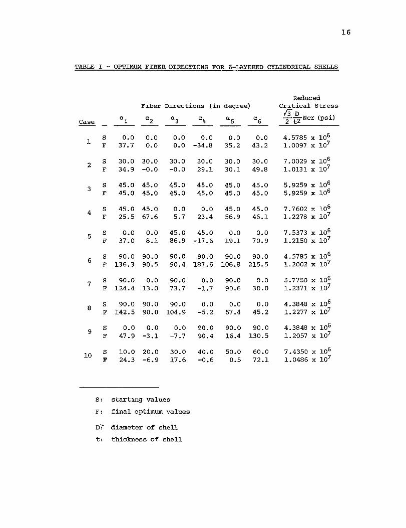
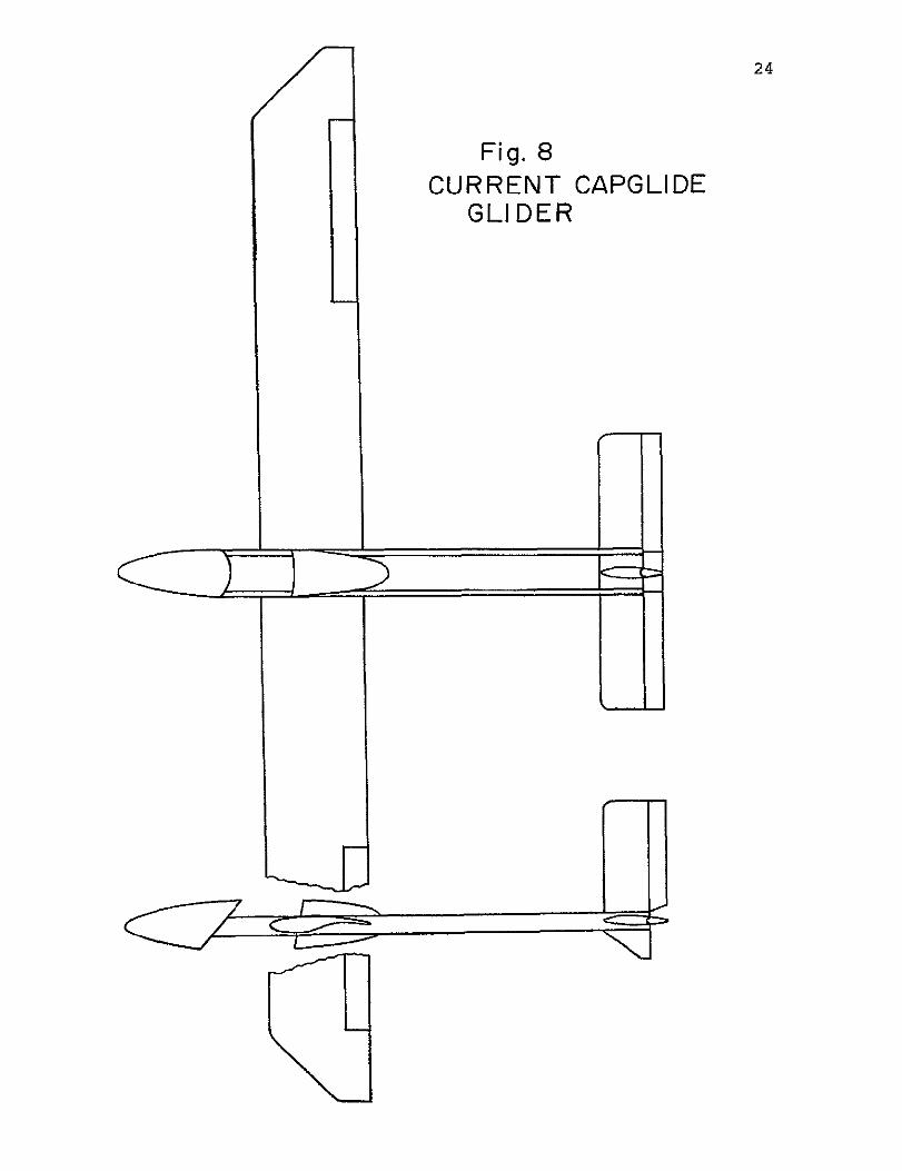
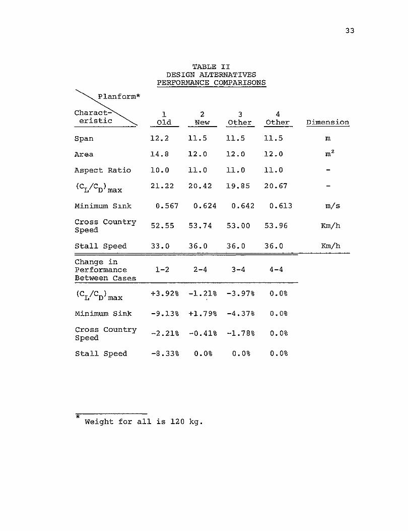
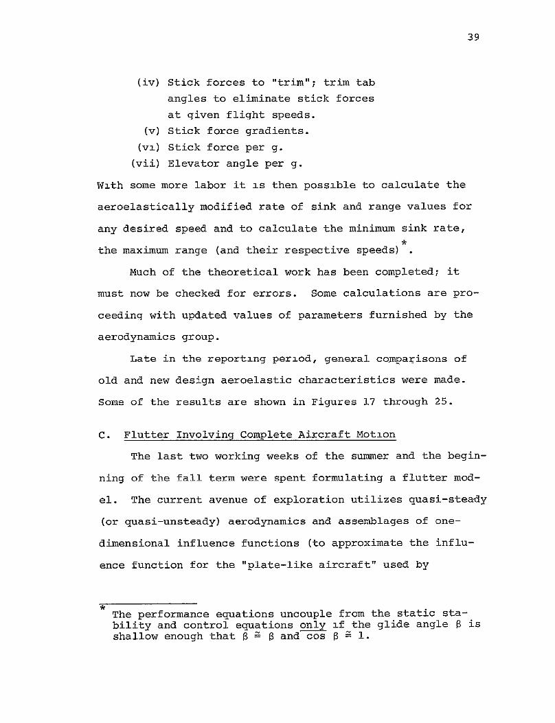
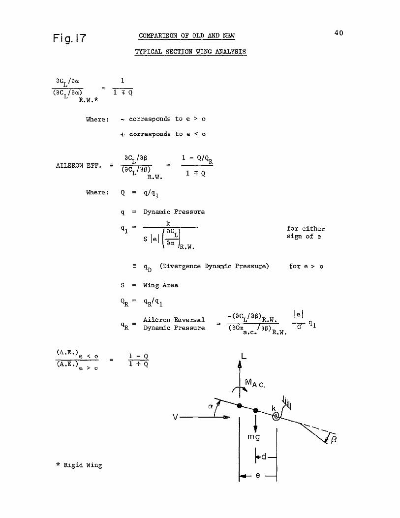
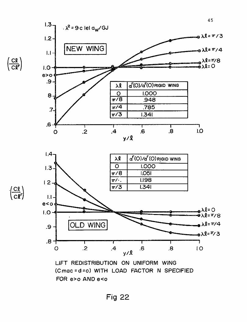
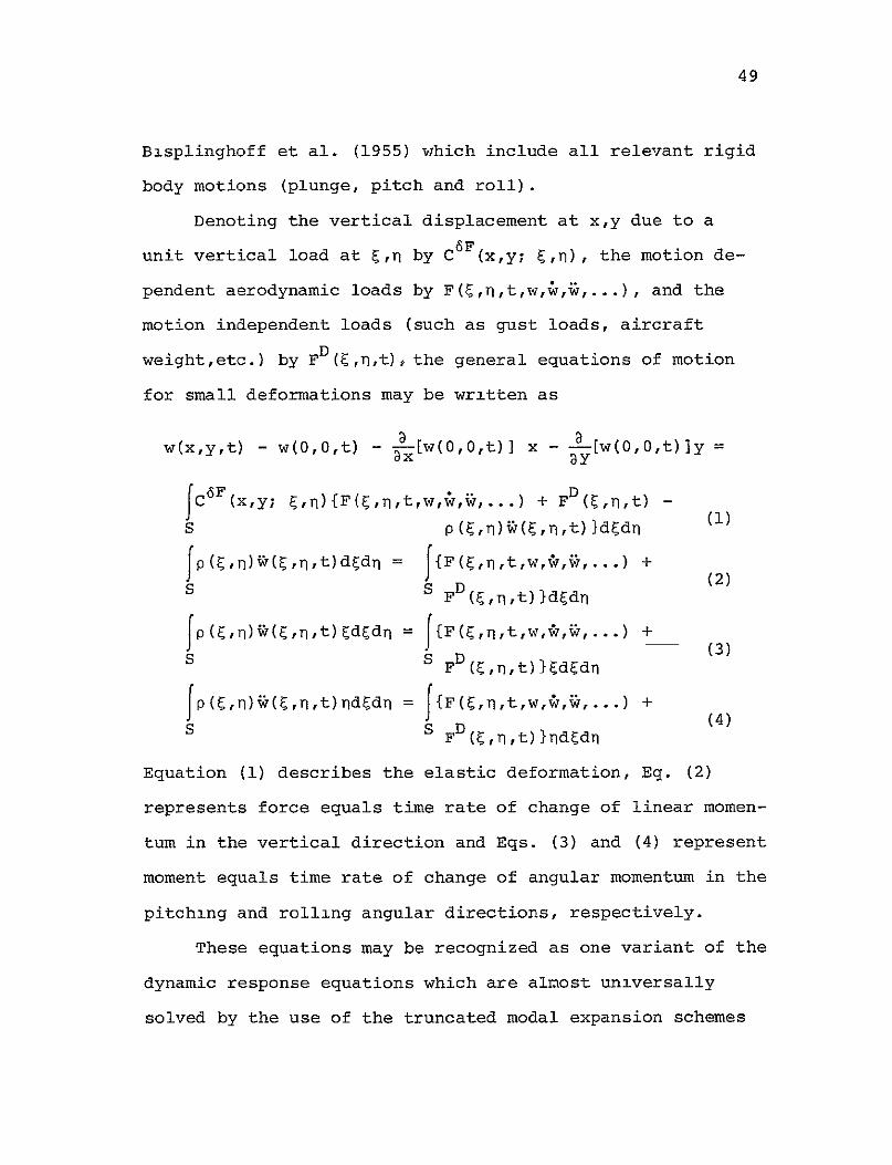
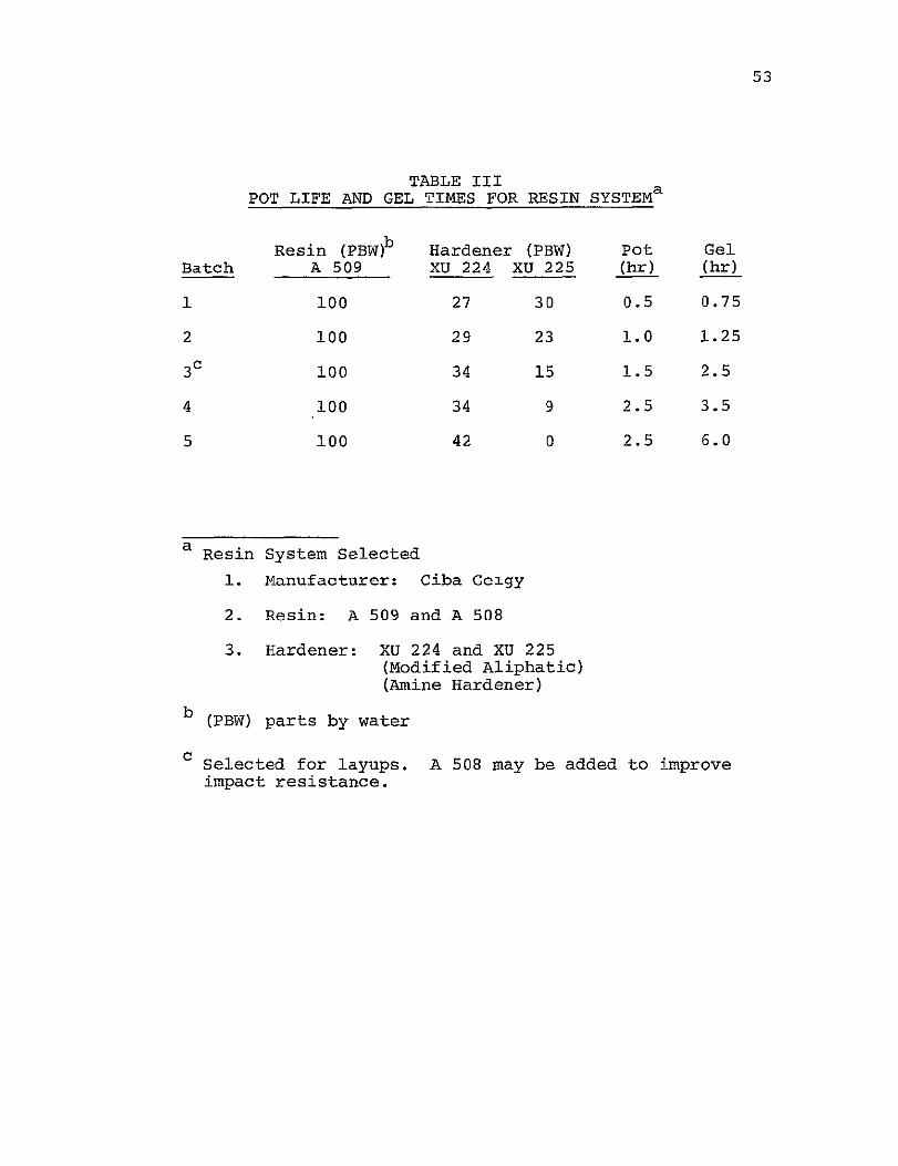
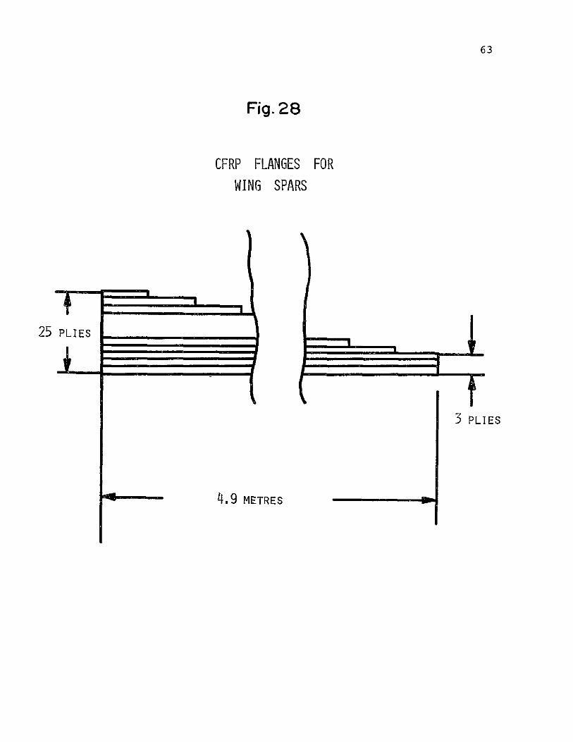
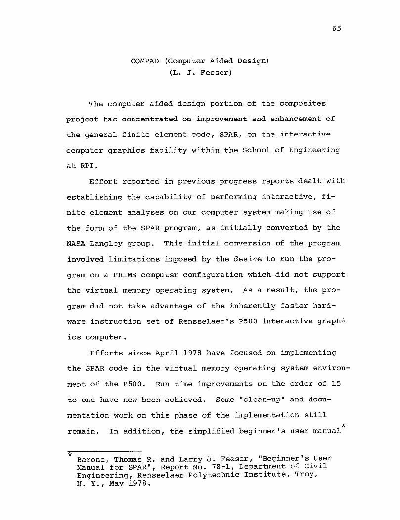

83
AUTHOR INDEX
Page
Brunelle E J Jr 18
Das P K 73
Diefendorf R J 18
Feeser L J 65
Hagerup H J 18
Helwig G 18
Hirano Y i1
Hoff N J 1118
Krempl E 71
Sternstein S S 68
Stoloff N S 76
Tiersten H F 73