L l III R li bilit B d D iLevel III Reliability Based ... 2/Lecture 5... · L l III R li bilit B d...
70
L l III R li bilit B dD i Level III Reliability Based Design of Examples set by ETC10 Y. Honjo, T. Hara & T.C. Kieu Le Gifu University Japan Gifu University, Japan 2nd International Workshop on Evaluation of Eurocode 7, Pavia, Italy, April 2010
Transcript of L l III R li bilit B d D iLevel III Reliability Based ... 2/Lecture 5... · L l III R li bilit B d...

L l III R li bilit B d D iLevel III Reliability Based Design of Examples set by ETC10p y
Y. Honjo, T. Hara & T.C. Kieu LeGifu University JapanGifu University, Japan
2nd International Workshop on Evaluation of Eurocode 7, Pavia, Italy, April 2010

RBD (Reliability Based Design) Level III, II and ITwo sources of LSD in Structural Eurocodes
( Structural vs. Geotechnical )Le el III RBD method emplo ed in this st dLevel III RBD: method employed in this study
Uncertainties and calculation procedureEX2-1: Pad foundation on homogeneous sandEX2 1: Pad foundation on homogeneous sand
SLS – design for settlementULS – design for stability
EX2-5: Embankment on peat groundConclusion
S ( S f h d)RSM (Response Surface Method)General conclutions

Design Basic Variables Reliability VerificationMethod Assessment
Level III Random variables Failure CostLevel IIIFull distribution
Random variablesProbability distributions
Failure Probability
Cost Optimization etc.
Level IIFORM and β
Random variablesMean, SD & Covariances(Distribution Free)
Reliability index β
Target βT
(Distribution Free)
Level IPartial factors
Deterministic variables Partial factorsLRFD
Verification formulaPartial factors LRFD

81.
0
y
0.6
0.8
ty D
ensi
ty
S
0.2
0.4
Pro
babi
lit
R
0 2 4 6 8 10
0.0
0P
0 2 4 6 8 10
S , R [ ]fP P R S= ≤[ ]Design structures so that
f
f fTP P≤

.81.
0
ity .40.
5
ity Failure Safe
0.4
0.6
0
babi
lity
Den
si
SR
0.2
0.3
0
bilit
y D
ensi
M
Failure Safe
0 2 4 6 8 10
0.0
0.2
Pro
b
0.0
0.1
0
Pro
ba
0 2 4 6 8 10
S, R -2 0 2 4 6
MM R S= −2 2
2
where : resistance ( , ) : force ( , )
: safety margin and ( )R R S SR R N S S N
M M N
μ σ μ σ
μ σ
∼ ∼
2 2 2
: safety margin, and ( , )
where , M M
M R S M R S
M M N μ σ
μ μ μ σ σ σ= − = +
∼
[ ] therefore, 0fP P M= ≤

M R S= −
2 2R SM
M R S
μ μμβσ σ σ
−→ = =
+Failure Safe
2
: safety margin: resistance ( , )R R
MR N μ σ∼
2: force ( , ): reliability index
S SS N μ σβ
∼
[ ]y0fP P M
β= ≤
Table 1 3 Relationship between β and P (Normal distribution)
M
Table 1.3 Relationship between β and Pf (Normal distribution)
Pf 10-1 5 x 10⁻² 10-2 10-3 10-4
β 1.28 1.64 2.32 3.09 3.72

Table 1.1 β recommended in EN 1990 annex Bβ
Reliability class (RC)
Min β for 50 years for U.L.S.
Limit State Target β for 50 years (RC2)
RC3 4.3 U.L.S. 3.8RC2 3.8 Fatigue 1.5 – 3.8RC1 3.3 S.L.S. 1.5 (irreversible)
Table 1.2 Target β values (life time examples) in ISO2394
Relative cost of safety measures
Consequences of failurelittle some moderat
egreat
y ehigh 0.0 1.5 2.3 3.1moderate 1.3 2.3 3.1 3.8
2nd International Workshop on Evaluation of Eurocode 7, Pavia, Italy, April 2010
moderate 1.3 2.3 3.1 3.8low 2.3 3.l 3.8 4.3

1R R S Sd( )+ ≥ +
SdSe
FR R S S
st s d e( )+ ≥ +
/ /t Rt s Rs Sd d Se eR R S Sγ γ γ γ+ ≥ +
Rs
t Rt s Rs Sd d Se eγ γ γ γRt
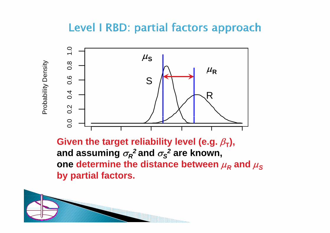
B d t i i ti l f t b d L l II III RBDBy determining partial factors based on Level II or III RBD,one can incorporate the intended safety margin (e.g. βT) Into structures This is the mission of code writers to fixInto structures. This is the mission of code writers to fix these partial factor values in this way (code calibration).
81.
0
ty
μS0.
60.
8
ity D
ensi
t
SμR
0.2
0.4
Pro
babi
l
R
0 2 4 6 8 1 0
0.0
Given the target reliability level (e g βT)S , R
Given the target reliability level (e.g. βT),and assuming σR
2 and σS2 are known,
one determine the distance between μR and μSR Sby partial factors.

RBD (Reliability Based Design) Level III, II and ITwo sources of LSD in Structural Eurocodes
( Structural vs. Geotechnical )Le el III RBD method emplo ed in this st dLevel III RBD: method employed in this study
Uncertainties and calculation procedureEX2-1: Pad foundation on homogeneous sandEX2 1: Pad foundation on homogeneous sand
SLS – design for settlementULS – design for stability
EX2-5: Embankment on peat groundConclusion
S ( S f h d)RSM (Response Surface Method)General conclutions

Structure Engineering• Classic Reliability based Design by Fredenthal et al. (from 1940th)• FOSM by Cornell(1969) and FORM by Ditlevsen (1973); Hasofer &
Lind (1974) etc.• Activities of JCSS (Joint Committee on Structural Safety)• Eurocodes 0,1,2,3 …
Geotechnical Engineering• Brinch Hansen (1956, 1967) and Danish Code of Practice for
F d i S (LSD d i l f f f )Foundation Structures (LSD and partial factors of safety)• K.N. Ovesen et al., Draft model code for Eurocode 7 (1987)• Eurocode 7

1950-1960Classic RBD
Freudenthal, Shinozuka
FOSM
1976-1990
JOSS 1990-date(Cornell、1968)
FORM(Ditlevsen, 1973; H f & Li d
(joint committeeOn Structural Safety) EN1990
And otherHasofer & Lind,
1974etc.)Rakowviz
First drafts of Eurocodes
ISO2394
Eurocodes

Brinch Hansen (1956, 1967)
and Danish Code of K.N. Ovesen et al.,Draft model code
Eurocode 7
ENV 1997 1(1994)Practice for Foundation
Structures
for Eurocode 7 (1987)
ESSMFE
ENV 1997-1(1994)Cases A, B and C
EN1997 1(2004)
Partial safety factorsLSD
EN1997-1(2004)Design Approaches
1,2 and 3

A consistent code formulation of a detailed partial safety factor principle was started inpartial safety factor principle was started in the 1950's in Denmark before other places in the world. This development got p gparticular support from the considerations of J. Brinch Hansen who applied the principles i h fi ld f il h iin the field of soil mechanics.
(Di l d M d(Ditlevsen and Madsen, Structural Reliability Methods (1996), p.31)

Try to fill the gap between the two approaches i e geotechnical andapproaches, i.e. geotechnical and structural, or EC7 and other ECs.
Estimate degree of reliability embeddedEstimate degree of reliability embedded in various design so as to make comparison of reliability possiblecomparison of reliability possible among various design results.

RBD (Reliability Based Design) Level III, II and ITwo sources of LSD in Structural Eurocodes
( Structural vs. Geotechnical )Le el III RBD method emplo ed in this st dLevel III RBD: method employed in this study
Uncertainties and calculation procedureEX2-1: Pad foundation on homogeneous sandEX2 1: Pad foundation on homogeneous sand
SLS – design for settlementULS – design for stability
EX2-5: Embankment on peat groundConclusion
S ( S f h d)RSM (Response Surface Method)General conclutions

Load Uncertainty
DesignUse Ground
ModelGround
Real Ground
DesignResult
Ground
Spatial Variability+
Measurement Error
Transforma-tion Error
Modeling UncertaintyStatistical Estima-
tion Error
tion Error Uncertainty
SPT N-value
SPT N-value
φ’-value
mean±SD mean±SD
φ -value
2nd International Workshop on Evaluation of Eurocode 7, Pavia, Italy, April 2010
mean±SD mean±SD

EX2-1 SLSSpatial
variabilityTransforma-
tion errorLoad
uncertaintyResponse
surfaceReliabilityanalysis
EX2-1 SLS
EX2-1 ULS
Spatialvariability
Transforma-tion error
Modelerror
Performancefunction
Reliabilityanalysis
EX2-5
Spatialvariability
Modelerror
Responsesurface
Reliabilityanalysis
EX2-5
y y
Geotechnical Design RBD

RBD (Reliability Based Design) Level III, II and ITwo sources of LSD in Structural Eurocodes
( Structural vs. Geotechnical )Le el III RBD method emplo ed in this st dLevel III RBD: method employed in this study
Uncertainties and calculation procedureEX2-1: Pad foundation on homogeneous sandEX2 1: Pad foundation on homogeneous sand
SLS – design for settlementULS – design for stability
EX2-5: Embankment on peat groundConclusion
S ( S f h d)RSM (Response Surface Method)General conclutions

2nd International Workshop on Evaluation of Eurocode 7, Pavia, Italy, April 2010

Spatialvariability
Transforma-tion error
Loaduncertainty
Responsesurface
Reliabilityanalysis
20
20
42
epth
(m)
4
Dep
th (m
)
6
De
6
D0 5 10 15 20 25 30
8
-5 0 5
80 5 10 15 20 25 30
CPT1 qc (MPa) CPT qc residuals (MPa)
Mean value: 10.54 1.66 (MPa)St d d d i ti 2 28 0 7 1 60 (MP )
cq z= +
2nd International Workshop on Evaluation of Eurocode 7, Pavia, Italy, April 2010
Standard deviation: 2.28 0.7 1.60 (MPa)× =

Spatialvariability
Transforma-tion error
Loaduncertainty
Responsesurface
Reliabilityanalysis
horizontal auto correlation
81.
0
1.0
horizontal auto-correlation
40.
60.
8
on c
oeffi
cien
t 0.5
on c
oeffi
cien
t
00.
20.
4
auto
corre
lati
0.0co
rrela
tio
0.0 0.5 1.0 1.5 2.0
0.0
lag distance (m)
0 5 10 15 20
-0.5
horizontal distance (m)
2nd International Workshop on Evaluation of Eurocode 7, Pavia, Italy, April 2010
lag distance (m) horizontal distance (m)

Spatialvariability
Transforma-tion error
Loaduncertainty
Responsesurface
Reliabilityanalysis
M l 1054 166 (MP )
200
500 Mean value: 10.54 1.66 (MPa)
Standard deviation: 2.28 0.7 1.60 (MPa)cq z= +
× =
5010
0
' (M
Pa)
'0' 5( )
(1 ')(1 2 ')' '
c vD q
E D
σν ν
= −+ −
020
D
( )( )' '(1 ')
E D ν νν
=−
2 5 10 20 50 100 200
510 NCHRP (2007)
CPT qc (MPa)
{ } (1 0.2)(1 2 0.2)' 5 (10.54 1.66 ) 0.02(1 0.2)
E z z + − ×= × + − ×
−
2nd International Workshop on Evaluation of Eurocode 7, Pavia, Italy, April 2010
47.43 7.38 ( )z MPa= +

Spatialvariability
Transforma-tion error
Loaduncertainty
Responsesurface
Reliabilityanalysis
PDF of the bias
1.0
1.2 05( ' )
'c v
Eq
Dσδ −=
Den
sity
0.6
0.8
1 D
Mean of δE = 1.14
0.2
0.4
Mean of δE 1.14SD of δE =0.94Following Lognormal
The bias of the transformation
1 2 3 4 5
0.0
Following Lognormaldistribution
2nd International Workshop on Evaluation of Eurocode 7, Pavia, Italy, April 2010

Spatialvariability
Transforma-tion error
Loaduncertainty
Responsesurface
Reliabilityanalysis
Permanent load (Gk)
δGk 1.0 0.1 Normal(2)
Variable load(Qk)
δQk 0.6 0.35x0.6=0.21
Gumbel distribution
Based on JCSS(2001) and Holicky, M, J. Markova and H. Gulvanessian (2007).
2nd International Workshop on Evaluation of Eurocode 7, Pavia, Italy, April 2010

Spatialvariability
Transforma-tion error
Loaduncertainty
Responsesurface
Reliabilityanalysis
Table 2.2 The settlement of the pad foundation by 3D PLAXISWidth B (m) 4 3 2 1 0.5
the relationship between B and s:
( )Settlement s (mm) 4.24 6.51 9.32 16.13 24.59
the relationship between B and s:s = 17.0 – 9.73 log B (7)(R2= 0.989), the perfect fit( ), pit is expected that the settlement would be double if Young’s modulus is half:
( 17 0 9 73 l B ) / I (8)s = ( 17.0 – 9.73 log B ) / IE (8)IE : a normalized Young’s modulus.
2nd International Workshop on Evaluation of Eurocode 7, Pavia, Italy, April 2010

Spatialvariability
Transforma-tion error
Loaduncertainty
Responsesurface
Reliabilityanalysis
mod
ulus
I_E
contour of sett lements (mm)
set
s
aliz
ed Y
oung
's
15
ongx
I
Nor
ma
5
10
20
25 30 35
40 25mm
Brx
Yo IEB
W idth of footing (m)
(1 0 9 3 )/2nd International Workshop on Evaluation of Eurocode 7, Pavia, Italy, April 2010
s = (17.0 – 9.73 log B)/IE

Spatialvariability
Transforma-tion error
Loaduncertainty
Responsesurface
Reliabilityanalysis
2⎛ ⎞2
2
(17.0 9.73log( )) f k Gk k Qk
E E f k k
D B G QBsI D B G Q
γ δ δδ γ
⎛ ⎞⋅ ⋅ + +−= ⎜ ⎟⎜ ⎟⋅ ⋅ ⋅ + +⎝ ⎠
2
2
20 1000 750(17.0 9.73log( ))20 1750
Gvk Qvk
E E
BBI
B δδ
δ⎛ ⎞⋅ + +−= ⎜ ⎟⎜ ⎟⋅ ⋅ +⎝ ⎠0 750E Eδ ⎝ ⎠
Basic variables NotationE i i f i l f E’ f 2( ) d hEstimation error of spatial average of E’ for 2(m) depth. ΙΕ
Transformation error on E’ δE
Permanent load δGk
Variable load δQk
2nd International Workshop on Evaluation of Eurocode 7, Pavia, Italy, April 2010
Qk

Spatialvariability
Transforma-tion error
Loaduncertainty
Responsesurface
Reliabilityanalysis
Nota- mean SD DistributionBasic variables
Nota-tion
mean SD Distribution type
Estimation error of E E’=47 43 7 2(MPa) NormalEstimation error of spatial average of E’ for 2(m) depth.
E E 47.43 + 7.38 z (MPa)
7.2(MPa)COV=0.12(1)
at z=1.5(m)
Normal
Transformation error on E’
δE 1.14 0.94 Lognormal
Permanent load δGk 1 0 0 1 Normal(2)Permanent load δGk 1.0 0.1 NormalVariable load δQk 0.6 0.35x0.6
=0.21Gumbel distribution(2)
(Note 1) COV at about z=1.5 (m) is calculated to represent estimation error of E’ based on limited number of samples.(Note 2) Based on JCSS(2001) and Holicky M J Markova and
2nd International Workshop on Evaluation of Eurocode 7, Pavia, Italy, April 2010
(Note 2) Based on JCSS(2001) and Holicky, M, J. Markova and H. Gulvanessian (2007).

Spatialvariability
Transforma-tion error
Loaduncertainty
Responsesurface
Reliabilityanalysis
SLS:500 SLS:
the settlement 25 ( )
0.20
00.
5
y < 25 (mm) After 100,0000
CS050
0.10
0
ance
pro
babi
lity
(5 % or beta=1.64)
(6.7 % or beta=1.5)
MCS runs.(R language)0.
020
0.0
5 (m
m) e
xcee
da
if β > 1.5 (i.e. 6.7% 00
50.
010
s >
25
(1 % or beta=2.32)
(exceedance in 50 years) 1 2 3 4 5
0.0
2nd International Workshop on Evaluation of Eurocode 7, Pavia, Italy, April 2010
y )B > 2.4 (m)
Width of footing (m)

RBD (Reliability Based Design) Level III, II and ITwo sources of LSD in Structural Eurocodes
( Structural vs. Geotechnical )Le el III RBD method emplo ed in this st dLevel III RBD: method employed in this study
Uncertainties and calculation procedureEX2-1: Pad foundation on homogeneous sandEX2 1: Pad foundation on homogeneous sand
SLS – design for settlementULS – design for stability
EX2-5: Embankment on peat groundConclusion
S ( S f h d)RSM (Response Surface Method)General conclutions

Spatialvariability
Transforma-tion error
Modelerror
Performancefunction
Reliabilityanalysis
0.5' 17.6 11.0log'
c
atc
qpφ
⎛ ⎞⎛ ⎞⎜ ⎟⎜ ⎟⎝ ⎠= + ⎜ ⎟⎛ ⎞⎜ ⎟
0
0'vap
σ⎛ ⎞⎜ ⎟⎜ ⎟⎜ ⎟⎝ ⎠⎝ ⎠
42
h (m
)
where pa = atmospheric pressure(0.1MPa)6
4
Dep
th
σ’v0 = effective overburden stress. 8
SD for transformation =2.8 (degree).
40 42 44 46 48 50
Phi (degree)
2nd International Workshop on Evaluation of Eurocode 7, Pavia, Italy, April 2010
g(Kulhawy et al. 1990)
Spatialvariability
Transforma-tion error
Modelerror
Performancefunction
Reliabilityanalysis
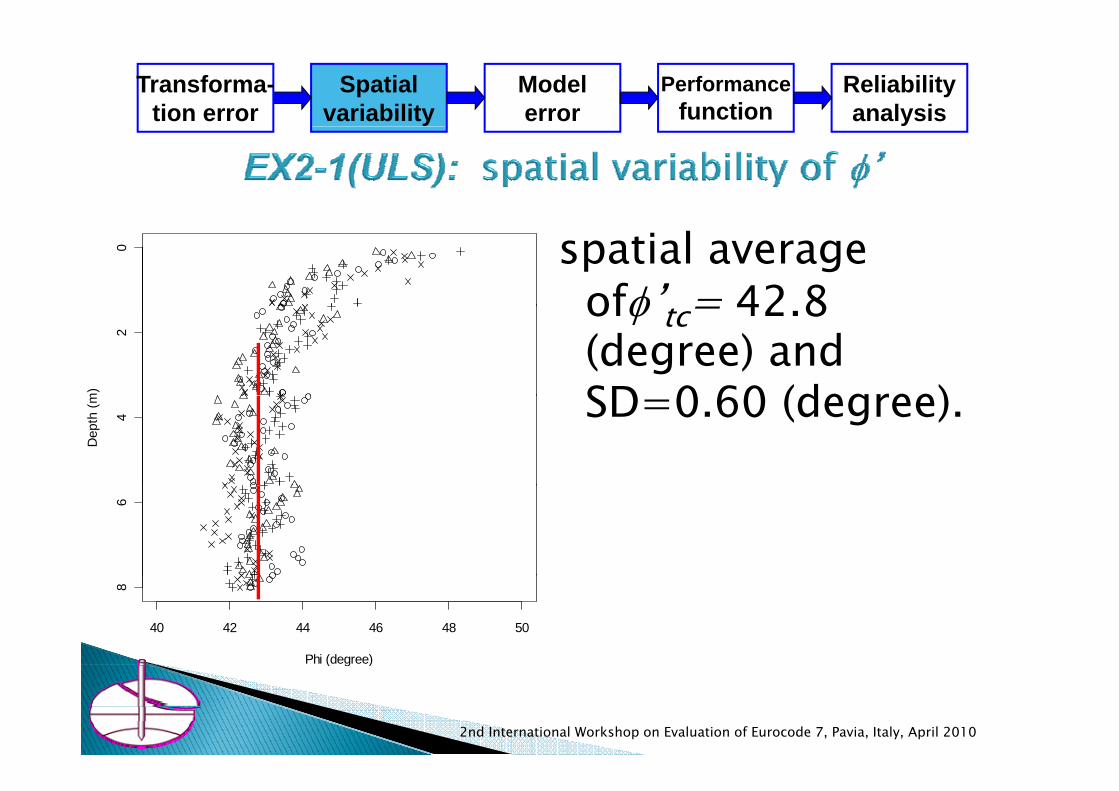
spatial average ofφ’ = 42 8
0
ofφ tc= 42.8 (degree) and SD 0 60 (degree)
2
m) SD=0.60 (degree). 4
Dep
th (m
6
40 42 44 46 48 50
8
Phi (degree)
2nd International Workshop on Evaluation of Eurocode 7, Pavia, Italy, April 2010
( g )

Spatialvariability
Transforma-tion error
Modelerror
Performancefunction
Reliabilityanalysis
where Ae = the effective area of the1R A N S B N Sβ⎧ ⎫+⎨ ⎬where Ae the effective area of the
foundation (=B2), Be = effective width (in this case Be =B ), κ and β = shape factors for N
1. . . . . . . .2u e q q eR A q N S B N Sγ γκ γ β⎧ ⎫= +⎨ ⎬
⎩ ⎭' 0.8 0.241 0.3 1 0.3 1f
e e e
DB B B
κ = + = + = +
κ and β = shape factors for NqNg, q = overburden pressure at the
foundation bottom, ( )
22. 20 0.8 16 (kN/m )
1 sin .exp .tan1 sin
f
q
q D
N
γ
φ π φφ
= = × =
+=
−
D’f = embedded depth (m), Sq and Sγ = scale factor for Nq and Nγ. B0 and q0 = reference width and load ( )
1/ 3 1/ 3
0
3
16 0.8610
20 kN/m
qqSq
γ
− −⎛ ⎞ ⎛ ⎞= = =⎜ ⎟ ⎜ ⎟⎝ ⎠⎝ ⎠
= 0 q0respectively.
Kohno et al (2009) Model error:
( )1 20 kN/mγ =
( ) ( )0.6
1 tan 1.4qN Nγ
β
φ
=
= − × Kohno et.al (2009) Model error:the bias =0.894 with SD = 0.257.
1/ 3 1/ 31/ 3
0 1.0e e
eB BS BBγ
− −−⎛ ⎞ ⎛ ⎞= = =⎜ ⎟ ⎜ ⎟
⎝ ⎠⎝ ⎠
2nd International Workshop on Evaluation of Eurocode 7, Pavia, Italy, April 2010

Spatialvariability
Transforma-tion error
Modelerror
Performancefunction
Reliabilityanalysis
tc( )', R ku Gk QkkM Ru B G Qφ δ δ δ= ⋅ − ⋅ − ⋅where M = safety margin, Ru = bearing capacity of the foundation,
Basic variables Notation Mean SD Distribution type
y g , g p y ,Gk =1000(kN), Qk = 750(kN) , B=width of footing
Spatial variability φ’tc 42.8 0 Deterministic variable
Transformation error φ’tc 42.8 2.8 Normalfrom qc to φ’tcRu estimation error δRu 0.894 0.257 Lognormal
Permanent action δGk 1.0 0.1 Normal
Variable action δQk 0.6 0.35x0.6=0.21 Gumbel distribution
2nd International Workshop on Evaluation of Eurocode 7, Pavia, Italy, April 2010

Spatialvariability
Transforma-tion error
Modelerror
Performancefunction
Reliabilityanalysis
Aft 100 000 MCSAfter 100,000 MCS runs
1e-0
1
β= 3.8 1e-0
2
babi
lity
(i.e. 10-4 failure probability for 1e
-03
Failu
re P
rob
50 years design working life. )
51e
-04 (0.0001 or beta=3.8)
B=2.2 (m)0.5 1.0 1.5 2.0 2.5 3.0
1e-0
5
Foundation width (m)
2nd International Workshop on Evaluation of Eurocode 7, Pavia, Italy, April 2010
B 2.2 (m)Foundation width (m)

Limit state Target β for 50 years design working life. (Pf)
Required width (m)
S.L.S.(s < 25 mm) 1.5 (0.067) B > 2.4 (m)U.L.S.(stability) 3.8 (10-4) B > 2.2 (m)
2nd International Workshop on Evaluation of Eurocode 7, Pavia, Italy, April 2010

1 If all average values obtained for basic variables1. If all average values obtained for basic variables SLS: only 0.5 (m) -> 2.4 (m) (4.8 times) ULS: 0.85 (m) for -> 2.2 (m) (2.6 times)ULS: 0.85 (m) for > 2.2 (m) (2.6 times)
2. The uncertainty components contributing the designgthe conversion of qc to Young’s modulus for settlement (SLS). the model error in the bearing capacity equation for bearing capacity (ULS). Th t ib ti f ti l i bilit f ilThe contribution of spatial variability of soil properties on total uncertainty is not as large.
2nd International Workshop on Evaluation of Eurocode 7, Pavia, Italy, April 2010

RBD (Reliability Based Design) Level III, II and ITwo sources of LSD in Structural Eurocodes
( Structural vs. Geotechnical )Le el III RBD method emplo ed in this st dLevel III RBD: method employed in this study
Uncertainties and calculation procedureEX2-1: Pad foundation on homogeneous sandEX2 1: Pad foundation on homogeneous sand
SLS – design for settlementULS – design for stability
EX2-5: Embankment on peat groundConclusion
S ( S f h d)RSM (Response Surface Method)General conclutions

An embankment on a soft peat with final height 3 (m)determine the first stage embankment height.
The Embankment materialγ=19 (kN/m3) , φ’k=32 5 (degree)
0
φ k=32.5 (degree).Top soil : normally consolidated clay (γ =18 (kN/m3) and γ’ = 9 (kN/m3) 3 ( ) h k l
2
(m)
3 to 7 (m) thick peat layer with γ’ =2 (kN/m3) overlaying Pleistocene sand of γ’ =11 (kN/m3) and φ’k =35 (degree).6
4
Dep
th
(kN/m ) and φ k 35 (degree). 5 filed vane test (FVT) results are given whose testing interval is 0.5 (m)
0 5 10 15 20 25
8
2nd International Workshop on Evaluation of Eurocode 7, Pavia, Italy, April 2010
0 5 10 15 20 25
FVT (kPa)

Spatialvariability
Modelerror
Responsesurface
Reliabilityanalysis
Undrained shear strength of the topsoil
Mean (kPa) SD (kPa) COV21.04 3.44 0.163
Undrained shear strength of the topsoil
Alternative models fitted to su of the peat layer
Models Trend (kPa) SD AIC Note
Constant 10 33 2 89 196 52Constant 10.33 2.89 196.52Linear 9.3677 + 0.3221z
(9.40) (1.085)2.85 197.30 R2 = 0.031
(t-values)Quadratic 14.73 - 3.51z + 0.536z2
(9.04) (3.42) (3.85)2.40 185.82 R2 = 0.314
(t-values)
2nd International Workshop on Evaluation of Eurocode 7, Pavia, Italy, April 2010

Spatialvariability
Modelerror
Responsesurface
Reliabilityanalysis
0 0
2 2
4
Dep
th (m
)
4
Dep
th (m
)
6 6
0 5 10 15 20 25
8
FVT (kPa)
-6 -4 -2 0 2 4 6
8
FVT residuals (kPa)FVT (kPa)
su = 14.73-3.51z+0.536z2 (kPa)the SD of the su -> 2.40 x 0.5 = 1.20 (kPa).
2nd International Workshop on Evaluation of Eurocode 7, Pavia, Italy, April 2010
( )

Spatialvariability
Modelerror
Responsesurface
Reliabilityanalysis
h (m) I I D (m)h (m) Ipeat Itopsoil Dt (m)
1, 1.5, 2, 2.5. 3 0.5, 0.75, 1.0 0.5, 0.75, 1.0 0.5,0.75, 1.0
(mean of of the peat layer)
(mean of of the topsoil) 21.04peat u u
topsoil u u u
I s s
I s s s
=
= =p
model equation r.s.e. R2
Linear Fs=0.948-0.449 h + 1.154 Ipeat + 0.0985 0.823p0.272 Itopsoil + 0.047 Dt
Quadratic Fs=1.783-1.351 h + 0.213 h2 + 1.156 I + 0 272 I + 0 091 D
0.0533 0.949Ipeat + 0.272 Itopsoil + 0.091 Dt
logalismic Fs=0.595-0.915 log(h) + 1.181 Ipeat + 0.272 Itopsoil + 0.079 Dt
0.0645 0.924
2nd International Workshop on Evaluation of Eurocode 7, Pavia, Italy, April 2010

Spatialvariability
Modelerror
Responsesurface
Reliabilityanalysisvariability errorsurface analysis
2.0
3.0
T il thi k 0 75 ( )
1.5
or
Ipeat=1.0
2.5
or
Topsoil thickness = 0.75 (m)
Topsoil Su = 21.0 (kPa)
Peat Su = 14.7-3.51z+0.536z^2 (kPa)
1.0
safe
ty fa
cto
Ipeat=0.752.0
Saf
ety
Fact
o
F 1 3 Ipeat=0.5
Itopsoil=0.75
1.5 Fs=1.3
B=2 2m0.0 0.5 1.0 1.5 2.0 2.5 3.0
0.5
hight of the embankment (m)
1.0 1.5 2.0 2.5 3.0
1.0
Height of embankment (m)
B=2.2m
2nd International Workshop on Evaluation of Eurocode 7, Pavia, Italy, April 2010

Spatialvariability
Modelerror
Responsesurface
Reliabilityanalysisvariability errorsurface analysis
64
56
N=39
Freq
uency
23
0.90 0.95 1.00 1.05 1.10 1.15 1.20
01
Safety Factor
Model error (Matsuo and Asaoka, 1976)

Spatialvariability
Modelerror
Responsesurface
Reliabilityanalysis
Basic variables Notations mean SD Distribution
Topsoil su (kPa) supeat21.04(1 0)
3.44(0 163)
Normalupeat
(Ipeat)(1.0) (0.163)
Peat su (kPa) sutopsoil(I )
14.73-3.51z +0.536z2
(1.0)1.20
(0.13)(1)Normal
(Itopsoil)( ) ( )
Topsoil thickness Dt[0.5, 1.0] (m) Uniform(2)
Model error δF[0.9, 1.0] Uniform(3)δFs[ ]
Unit weight of embankment γf
19.0(kN/m3) - Deterministic
friction of embankment φ 32 5 degree Deterministicfriction of embankment φf32.5 degree - Deterministic
Unit weight of topsoil γc9.0(kN/m3) - Deterministic
Unit weight of peat γ ’ 2.0(kN/m3) - DeterministicγP2.0(kN/m ) Deterministic
friction of sand φs35 degree - Deterministic
Unit weight of sand γs’ 11.0(kN/m3) - Deterministicγs(Note 1) su topsoil (at z=4.0(m)) = 14.73 - 3.5x4.0 + 0.53x4.02 = 9.27, COV=1.20/9.27=0.13(Note 2) It is assumed that the boundary of the topsoil and the peat layer lies somewhere between z = 0.5 to 1.0 (m).(Note 3) Based on Matsuo and Asaoka (1976).

Spatialvariability
Modelerror
Responsesurface
Reliabilityanalysis
The response surface for the safety factor
Fs=(1.783-1.351 h + 0.213 h2
+ 1.156 I t + 0.272 It il + 0.091 Dt)δFs 1.156 Ipeat 0.272 Itopsoil 0.091 Dt)δFs
After 100,000 MCS runs, to obtainAfter 100,000 MCS runs, to obtain Pf = P [ Fs<1.0 ]
2nd International Workshop on Evaluation of Eurocode 7, Pavia, Italy, April 2010

Spatialvariability
Modelerror
Responsesurface
Reliabilityanalysis
For β = 2 321e+0
0
For β = 2.32, the first stage
embankment1e-0
1
embankment height should be less than 2 1 (m)e-
021
py
1.0 % or beta=2.32 less than 2.1 (m).
e-03
104
1e
1.0 1.5 2.0 2.5 3.0
1e-0
Height of the embankment (m)
2nd International Workshop on Evaluation of Eurocode 7, Pavia, Italy, April 2010

Based on the RS, one can evaluate the contribution of each basic variable to the
f t f th b k t F lsafety of the embankment. For example, The effect of the height of the embankment becomes less as the embankment height increase, which is indicated by g , ythe quadratic function. 10% reduction of peat strength reduces the safety factor by 0.12. The reduction is 0.027 in case of the topsoil y pstrength.0.1 (m) change of the topsoil layer thickness changes the safety factor by 0.01.y y
Fs=(1.783-1.351 h + 0.213 h2
1 156 I 0 272 I 0 091 D )δ+ 1.156 Ipeat + 0.272 Itopsoil + 0.091 Dt)δFs
2nd International Workshop on Evaluation of Eurocode 7, Pavia, Italy, April 2010

RBD (Reliability Based Design) Level III, II and ITwo sources of LSD in Structural Eurocodes
( Structural vs. Geotechnical )Le el III RBD method emplo ed in this st dLevel III RBD: method employed in this study
Uncertainties and calculation procedureEX2-1: Pad foundation on homogeneous sandEX2 1: Pad foundation on homogeneous sand
SLS – design for settlementULS – design for stability
EX2-5: Embankment on peat groundConclusion
G l lGeneral conclusionsRSM (Response Surface Method)

1 Three out of six examples (i e EX2-1 5 and 6)1. Three out of six examples (i.e. EX2 1, 5 and 6) set by ETC10 – Evaluation of Eurocode 7 - has been solved by using Level III reliability based d idesign.
2. it is not soil properties spatial variability that controls the major part of the uncertainty in manycontrols the major part of the uncertainty in many geotechnical designs.
3. The error in design calculation equations, f i f il i i i l (transformation of soil investigation results (e.g.
SPT N-values, FVT, CPT qc) to actual design parameters (e.g. su, f’, resistance values), andparameters (e.g. su, f , resistance values), and statistical estimation error are more important factors.
2nd International Workshop on Evaluation of Eurocode 7, Pavia, Italy, April 2010

RBD (Reliability Based Design) Level III, II and ITwo sources of LSD in Structural Eurocodes
( Structural vs. Geotechnical )Le el III RBD method emplo ed in this st dLevel III RBD: method employed in this study
Uncertainties and calculation procedureEX2-1: Pad foundation on homogeneous sandEX2 1: Pad foundation on homogeneous sand
SLS – design for settlementULS – design for stability
EX2-5: Embankment on peat groundConclusion
G l lGeneral conclusionsRSM (Response Surface Method)

Uncertainty Quantification of x
Random numberGeneration of x
CSQuantification of x by MCS
•Statistical AnalysisG t h D t b
Basic variables: x
•Geotech. Database
Geotechnical Design to find Response
fUncertainty
fg
out y=F(x) relationships
surface y ~ F(x)
Evaluation of y:ex. P(y>y*)=Pf
Performance of structures: y(Outcomes)
2nd International Workshop on Evaluation of Eurocode 7, Pavia, Italy, April 2010

Uncertainty Quantification of x
Random numberGeneration of x
CSQuantification of x by MCS
•Statistical AnalysisG t h D t b
Basic variables: x
•Geotech. Database
Geotechnical Design to find Response
fUncertainty
fg
out y=F(x) relationships
surface y ~ F(x)
Evaluation of y:ex. P(y>y*)=Pf
Performance of structures: y(Outcomes) Purely Geotechnical Design
2nd International Workshop on Evaluation of Eurocode 7, Pavia, Italy, April 2010

Uncertainty Quantification of x
Random numberGeneration of x
CSQuantification of x by MCS
Some RBD tools•Statistical AnalysisG t h D t b
Basic variables: xtt
•Geotech. Database
Geotechnical Design to find Response
fUncertainty
f
tt
gout y=F(x)
relationships
surface y ~ F(x)
Evaluation of y:ex. P(y>y*)=Pf
Performance of structures: y(Outcomes)
2nd International Workshop on Evaluation of Eurocode 7, Pavia, Italy, April 2010

1 Release geotechnical engineers from the1. Release geotechnical engineers from the uncomfortable feelings for RBD tools by separating geotechnical design part and RBD part.g g p p
2. Monte Carlo simulation, a very straightforward tool, is only RBD tool employed.
3. The response surface (RS) itself contains considerable amount of useful design information.
4 Di h i l d i k h f4. Direct geotechnical designers to make the most of their knowledge, experiences and engineering judgments in obtaining the RSjudgments in obtaining the RS.
2nd International Workshop on Evaluation of Eurocode 7, Pavia, Italy, April 2010

2nd International Workshop on Evaluation of Eurocode 7, Pavia, Italy, April 2010


Galanbos, T.V. (1992): Design Code, in Engineering Safety, ed. D. Blockley, McGraw-Hill Book Com.
h f ( ) l f l dMayerhof, G.G.(1992) Development of limit state design, Proc. Int. Sym. on limit state design in geotechnical engineering, vol. 1, pp.1-12.Brinch Hansen, J. (1967): The philosophy of foundation design: criteria, safety factors and settlement limits, Bearing Capacity and Settlement of Foundations, ed. A. Vesic, Duke University.

Determine bored pile length LDetermine bored pile length L(m) (D = 0.45 m) spaced 2.0 (m) centres(m) centres
permanent load = 300 (kN) 1 0vertical variable load=150
(kN).
Pleistocene fine and medium sand covered by Holocene layers
2nd International Workshop on Evaluation of Eurocode 7, Pavia, Italy, April 2010

layer Soil description Depth (m) Mean SD(SPT N) (SPT N)
1 Clay with sand seams 0.0 - 1.9 7.5 3.662 Fine sand 1 9 - 2 9 14 8 4 582 Fine sand 1.9 2.9 14.8 4.583 Clay with sand seams 2.9 - 4.0 9.2 1.444 Fine silty sand 4.0 - 9.0 10.3 3.225 Fine silty sand with
clay & peat seams9.0 - 11.0 16.2 3.31
6 Clay with sand seams 11 0 - 12 3 10 1 1 456 Clay with sand seams 11.0 - 12.3 10.1 1.457 Clay with peat seams 12.3 - 13.0 11.1 1.518 Clay with peat seams 13.0 - 15.0 13.7 0.549 Fine sand 15.0 - 17.0 13.6 7.2410 Fine sand 17.0 - 27.0 3.71
2nd International Workshop on Evaluation of Eurocode 7, Pavia, Italy, April 2010

EX 2-6 : PILE FOUNDATION IN SANDTransformation of qc to SPT-NTransformation of qc to SPT-N
0 26
cqp 0.26
505.44ap DN
=
where pa = atmospheric pressure, pa p p ,D50 = 50% grain size of soil. No bias in the conversion but SD is 1.03.
Kulhawy and Mayne (1990 Fig 2 30)Kulhawy and Mayne (1990, Fig. 2.30),
2nd International Workshop on Evaluation of Eurocode 7, Pavia, Italy, April 2010

( ) ( )n
f ti i t i i qd a t n p Gk k Qk kM U f N L q N A G Qδ δ δ δ δ δ δ= + − −∑
here
1f q p Q
i=∑
where,δf : uncertainty of estimating pile shaft resistance, fi, by SPT-Nδ d : uncertainty of estimating pile tip resistance qd by SPT-Nδqd : uncertainty of estimating pile tip resistance, qd, by SPT Nδt : uncertainty of transformation from CPT qc to SPT-NδGk : uncertainty on characteristic value of permanent load.Gk y pδQk : uncertainty of characteristic value of variable load.
2nd International Workshop on Evaluation of Eurocode 7, Pavia, Italy, April 2010

Basic variable Mean SD Distribution Note
δGk 1.0 0.1 N Gk = 300 (kN) (1)
δQk 0.6 0.21 Gumbel Qk = 150 (kN) (1)
δ 1 07 0 492 LN Okahara et al (1991)δf 1.07 0.492 LN Okahara et.al (1991)δqd 1.12 0.706 LN Okahara et.al (1991)δt 1 1.03 LN Kulhawy & Mayne (1990)t y y ( )N1 7.51 3.66 N unit: SPT N-value
N2 14.80 4.58 N unit: SPT N-value
N3 9.24 1.44 N unit: SPT N-value
N4 10.33 3.22 N unit: SPT N-value
N5 16.17 3.31 N unit: SPT N-value
N5 10.08 1.45 N unit: SPT N-value
N7 11.14 1.51 N unit: SPT N-value
N8 13.68 0.54 N unit: SPT N-value
N9 13.56 7.24 N unit: SPT N-value
2nd International Workshop on Evaluation of Eurocode 7, Pavia, Italy, April 2010
N10 26.98 3.71 N unit: SPT N-value

pile length of more5 pile length of more than 18 (m) is necessary for
5
beta=3.8y
b=3.810
ngth
L (m
)
15Pile
le
General estimationLocal estimation
20
Local estimation
0 1 2 3 4 5
Reliability Index _ Beta
2nd International Workshop on Evaluation of Eurocode 7, Pavia, Italy, April 2010

EX 2-6 : PILE FOUNDATION IN SAND - results
β = 2.3 3.1 3.8
C id
5
beta=3.8Consider alluncertainty
11.5 15.0 18.010
th L
(m)
Excluding δqd
11.3 15.0 17.1
Excluding 9 5 12 0 13 3
15Pile
leng
All uncertaintyExcluding delta_qd g
δf9.5 12.0 13.3
Excluding δt
8.4 11.0 12.720
Excluding delta_fExcluding delta_t
δt0 1 2 3 4 5
Reliability Index _ Beta
2nd International Workshop on Evaluation of Eurocode 7, Pavia, Italy, April 2010

19th CenturyASD (Allowable Stress Design)1920 thUltimate Strength Design researches in
USSR and Eastern EuropepAfter World War IIClassic Reliability Based Design
(Freudenthal 1945 etc )(Freudenthal, 1945 etc.)LSD (Limit State Design)FOSM (First Order Second Moment
M h d) (C ll 1968)Method) (Cornell、1968)1970 thFORM (First Order Reliability Mehtod)(Ditlevsen, 1973; Hasofer & Lind,
1974etc.)Development of Structural Eurocodes(G ) Development of Structural Eurocodes(JCSS, Joint Committee on Structural Safety)
(Galambos, 1992)

Spatialvariability
Transforma-tion error
Loaduncertainty
Responsesurface
Reliabilityanalysis
Spatialvariability
Transforma-tion error
Modelerror
Performancefunction
Reliabilityanalysis
Spatial ModelResponse ReliabilitySpatialvariability
Modelerror
Responsesurface
Reliabilityanalysis

Failure probability is obtained By integrating portion of the distribution in failure region.
( , )F RSD
P f r s drds= ∫ ∫D