L Connection Network Control System For L Series Rooftop ... · The Comfort Sensor also means...
100
C O N T R O L S L Connection ® Network Control System For L Series ® Rooftop Units Bulletin No. 210474 October 2011 Supersedes December 2010 ENGINEERING DATA Commercial Building Automation System Advanced Single Point Control For HVAC Systems And Building Operation
-
Upload
truongthuy -
Category
Documents
-
view
219 -
download
2
Transcript of L Connection Network Control System For L Series Rooftop ... · The Comfort Sensor also means...

C O N T R O L S
L Connection® Network Control SystemFor L Series® Rooftop Units
Bulletin No. 210474October 2011
Supersedes December 2010
E N G I N E E R I N G D ATA
Commercial Building Automation SystemAdvanced Single Point Control
For HVAC Systems And Building Operation

L Connection® Building Automation System - L Series® / Page 2
CONTENTS
COMPONENT IDENTIFICATION
ContentsBuilding Controller . . . . . . . . . . . . . . . . . . . . . . . . . . . . .29Building Manager . . . . . . . . . . . . . . . . . . . . . . . . . . . . . .13Component Identification . . . . . . . . . . . . . . . . . . . . . . . . . . 2Features And Benefits . . . . . . . . . . . . . . . . . . . . . . . . . . . 3Integrated Modular Controller . . . . . . . . . . . . . . . . . . . . . . . .15Network Control Panel . . . . . . . . . . . . . . . . . . . . . . . . . . .13Network Thermostat Controller . . . . . . . . . . . . . . . . . . . . . . .25System Architecture . . . . . . . . . . . . . . . . . . . . . . . . . . . . 4System Components - Controllers . . . . . . . . . . . . . . . . . . . . .13System Components - Miscellaneous Accessories . . . . . . . . . . . .85System Components - Network. . . . . . . . . . . . . . . . . . . . . . .67System Components - Ordering Information . . . . . . . . . . . . . . . .96System Components - Sensors . . . . . . . . . . . . . . . . . . . . . .36System Components - Software . . . . . . . . . . . . . . . . . . . . . .76System Overview . . . . . . . . . . . . . . . . . . . . . . . . . . . . . . 6Zone And Bypass Dampers. . . . . . . . . . . . . . . . . . . . . . . . .82Zone Link . . . . . . . . . . . . . . . . . . . . . . . . . . . . . . . . . .32
C 0 SNSR 2 1 ae 1 l
Product FamilyC = Commercial Generic
S = S-Class™T = T-Class™
Product Type0 = Building Automation / Automatic Temperature Control
1 = Rooftops2 = Air Conditioners and Heat Pumps
3 = Indoor Coils / Air Handlers4 = Furnaces
5 = Unit Heaters / Duct Furnaces6 = General or Multi-Purpose
Basic DescriptionSNSR = Sensor
SNSJ = Sensor, AdjustableSNCT = Sensor / Controller
SNDC = Sensor, DuctSNMT = Sensor, Multiple Function
SNZN = Sensor, Zone (non-adjustable)STAT = Thermostat
CTRL = DDC Controller or InterfaceSWCH = Switch
SOFT = SoftwareMISC = Miscellaneous (cables, wire, etc.)
Specific Description 1 (example: CTRL)
Controller Description, 1 Digit0 = Lennox Unit Controller
1 = Lennox Network Controller2 = Lennox Building Controller
3 = Third-Party Controller4 = Systems Integration Software
(includes software drivers, configuration files, plug-ins, etc.)5 = Systems Integration hardware (gateway devices)
Specific Description 2(example: CTRL)Controller Description, 2nd DigitSpecific to Catalog Number(example: CTRL00 = Sectra Bypass Control Kit 23M51)
Box Size1st character is smallest applicable size2nd character is largest applicable sizeIf only certain sizes are applicable, letters can be placed out of sequence.(example: EA” applicable to A and E box sizes only)A = A-Box SizeB = B-Box Size and so on.
Design Sequence1 = 1st Revision 2 = 2nd Revision
Voltage (Only shown if voltage dependant)Y = 208/230V-3 PhaseG = 460V-3 PhaseJ = 575V-3 PhaseL = Low Voltage (typically 24V)

L Connection® Building Automation System - L Series® / Page 3
FEATURES AND BENEFITS
Save money and time and provide a higher level of control by commanding a wide range of functions from a single location. The L Connection® Network makes it easy to manage HVAC, zoning and building operations from a single point of control, minimizing energy and maintenance costs. It was designed to enhance the functionality and performance of Lennox’ premium rooftop units featuring the Integrated Modular Control (IMC) as well as other Lennox rooftop units and split systems. It is also fully compatible with electro-mechanically controlled third-party equipment. It’s a cost-effective way to minimize your building’s energy use and better manage facility operations.L Connection Network not only improves building efficiency and comfort, it also helps to improve staff efficiency and productivity. Temperature setpoints can be adjusted quickly and intuitively at the Comfort Sensor. For more advanced control, facility managers can access and troubleshoot other Lennox and electro-mechanically controlled third-party equipment along with the building’s lights and signage using local or remote interfaces.The Comfort Sensor combines optional relative humidity (RH) and carbon dioxide (CO2) sensor options with a temperature sensor. Optional zone controller capabilities are also available when the Comfort Sensor is used in commercial zoning applications. This means less wiring and fewer sensors to install separately, and more flexible comfort control with an optional LCD interface which allows you to easily adjust the temperature. The adjustable range can be configured to control energy use while optimizing comfort and productivity. The Comfort Sensor also means easier service for the zone controller in the zone.The Network Control Panel allows a facility manager advanced monitoring and control capabilities for troubleshooting and configuration adjustments, including scheduling, temperature set-point, humidity control and much more. Optional PC software provides access to a specific controller or the entire network locally, or remotely through a modem or the Internet (Internet access to Ethernet local area network (LAN) is required). This gives a facility manager or owner advanced control of their building from virtually anywhere and at any time. It also allows a servicing contractor to diagnose and troubleshoot remotely without sending someone to the site.
WARRANTY
Integrated Modular Controller (furnished with all Lennox’ premium rooftop units) - Limited three years.All other covered components - Limited one year.

L Connection® Building Automation System - L Series® / Page 4
NETWORK MANAGER PROVIDES A CENTRAL POINT OF ADVANCED CONTROL
Network Control Panel Located in facility manager’s office• Large screen and four-
button control provide a user-friendly interface to HVAC equipment and building functions.
• Customized settings with time-of-day scheduling, temperature, CO2, ventilation and humidity control.
• Date and time-stamped alarm codes.• Auto-poll start-up feature greatly reduces installation
time and expense.• Easily field-upgraded without losing programs or
schedules.• Provides a written description of each controller’s
alarm codes.
CONTROLLERS CONNECT EQUIPMENT TO THE NETWORK
Building ControllerLocated in control room or mechanical room• Schedules basic building
operations such as lights, signs and exhaust fans.
• Built-in diagnostics and alarm codes speed troubleshooting.
A
B
C
Integrated Modular ControllerStandard on Lennox’ premium rooftop units• Simplifies diagnostics and problem-solving.• Pre-programmed
with more than 200 control parameters that are factory-set for typical applications.
• Controls constant volume bypass or single zone units, or variable air volume units with factory variable frequency drives.
• Over 100 unit alarm codes.• Interfaces directly to the L Connection® Network,
standard thermostats or electro-mechanically controlled third-party automation systems.
• Built specifically to provide optimum control of Lennox’ premium rooftop units.
Network Thermostat ControllerIntegrates electro-mechanically controlled HVAC equipment• Monitors and controls Lennox’
split systems and rooftop units without the Integrated Modular Controller, as well as electro-mechanically controlled third-party equipment.
• Up to two-heat, three-cool capability.
• Can be combined with optional bypass controller for constant volume bypass zoning applications.
• Fused outputs and override switches simplify installation testing, set-up, and provide added protection.
D
E
SYSTEM ARCHITECTURE
• Network Control Panel provides a central control point for HVAC systems and basic building operation.
• Various Controllers connect the network components together.
• Zone Controllers and various Sensors provide control at each zone.
BC
DE F
G

L Connection® Building Automation System - L Series® / Page 5
ZONE CONTROLLERS AND SENSORS PROVIDE CONTROL AT EACH ZONE
Zone LinkLocated in the rooftop unit or mechanical room• Coordinates up to
31 Comfort Sensors connected to a zoned rooftop unit.
• Counts heating and cooling votes from Comfort Sensors and signals the rooftop unit to change modes according to its configuration.
• Expands L Connection Network to coordinate up to 93 unit controllers per network.
Comfort SensorLocated in each zone• Temperature sensor with optional
relative humidity and/or carbon dioxide sensing capabilities.
• Controls zone damper or variable volume terminal box in zoning applications to maintain space temperature and indoor environmental quality.
• Optional LCD user interface with sensor readings and easy temperature adjustment.
software sENDS information to a PC from the L Connection® Network locally or remotELY
Unit Controller Software• Commission, monitor
and control unit controllers, including Integrated Modular Controllers, Network Thermostat Controllers or Building Controllers.
• Connects to the network locally or remotely through a modem, rough an Ethernet network or through the Internet (requires access to Local Area Network (LAN) via an Internet connection).
F
G
H
SYSTEM ARCHITECTURE (CONTINUED)
Network Control Panel Software• Schedule, monitor and
control the entire L Connection Network.
• Configures alarms to automatically send e-mail, page, or text message notification to a facility manager or servicing contractor before problems get out of hand.
• Records trends based on over 25 user-selectable data points that can be automatically graphed using Microsoft® Excel.
• Generates, saves and prints a variety of reports.• Connects to the network locally or remotely through
a modem, through an Ethernet network or via the Internet.
Network Modem• Configured specifically for
the L Connection Network.• Plug-and-play device
requires no modification.• Use with L Connection
Network software for access from a remote site.
Ethernet Converter• Configured specifically for the L
Connection Network.• Allows users to monitor and control
devices on the L Connection network through their existing Ethernet local area network (LAN).
• Can be used to monitor and control devices on the L Connection Network remotely through the Internet.
• Can be used with Unit Controller Software and/or Network Control Panel Software.
• Software sends information to a PC from the L Connection Network locally or through a remote modem or Internet connection.
• Allows full monitoring and control of the network.
• Network can be controlled from a remote location.
H

L Connection® Building Automation System - L Series® / Page 6
36 ZONED UNITS
36 NCP DIRECT NODES
SYSTEM OVERVIEW
• The Network Control Panel is used to schedule building network operation on up to 450 HVAC zones and 12 Building Controllers.
• The Building Controller option adds capability for schedule or light sensor control for up to 8 outputs that can be used for lighting, fans, signage, etc.
• Up to 93 units per Network Control Panel.• Integrates single zone and zoned units on the same
network.• Connects directly to Lennox’ premium rooftop units.• Uses Network Thermostat Controller to control rooftop
units without the Integrated Modular Controller, split systems and third-party units.
• Many non-communicating space sensor options for temperature, relative humidity (RH) and CO2.
• Comfort Sensor options add capability for single unit setpoint control, built-in RH and CO2 sensors.
• Comfort Sensor-Zoning options add capability for zone terminal box control, built-in RH and CO2 sensors.
• Access at Network Control Panel or via local PC.• Remote access via phone modem or via LAN/Internet
with Ethernet Converter.
Zoning Applications• Up to 31 zones/unit.• Constant Air Volume Bypass (CAVB) and Variable Air
Volume (VAV) zoning systems.• Configurable for parallel and series fan
poweredterminal boxes.• Fan boxes may be used with VAV or CAV rooftop unit.• Can mix and match fan boxes, damper zones and
single zones.• Networked solution simplifies wiring.• Lennox’ variable air volume (VAV) units are zoning
ready.
NOTE - The L Connection® Network is not applicable to heat pump units or units equipped with the Humiditrol® option in multi-zone (Comfort Sensor Zoning) applications.
SYSTEM OVERVIEW

L Connection® Building Automation System - L Series® / Page 7
Net
wor
kC
ontro
lP
anel
Com
fort
Sen
sor
Lenn
ox’ P
rem
ium
RTU
(CAV
)
Lenn
ox’ P
rem
ium
RTU
(CAV
B)
Com
fort
Sen
sor-
Zoni
ng1
Com
fort
Sen
sor-
Zoni
ng1
Bui
ldin
gC
ontro
ller
SysBus Network Cable (Yellow)
ZoneBus Network Cable (Purple)
PC
Sof
twar
eN
etw
ork
Bus
to P
CC
onve
rter
IMC
VAV
Mod
ule
Kit
3
Sup
ply
Stat
icD
iffer
entia
lP
ress
ure
Sen
sor
3
Dam
per
Act
uato
r (B
ypas
s)
2Rem
ote
Dis
char
ge3
1−C
omfo
rt S
enso
r-Zo
ning
can
con
trol a
dam
per o
r fan
pow
ered
term
inal
box
.2-
Not
requ
ired
on V
FD e
quip
ped
Lenn
ox ro
ofto
p un
its.
3-A
utom
atic
ally
incl
uded
with
VFD
equ
ippe
d Le
nnox
roof
top
units
.
SYST
EM C
OM
PON
ENT
SELE
CTI
ON
EXA
MPL
E −
BA
SIC
OVE
RVI
EWLe
nnox
Roo
ftop
Uni
ts W
ith In
tegr
ated
Mod
ular
Con
trol
ler (
IMC
)(N
OTE
− IM
C a
nd N
etw
ork
Ther
mos
tat C
ontr
olle
r con
trol
led
units
can
be
com
bine
d on
the
sam
e sy
stem
)
RTU
#2
(Zon
ed)
RTU
#1
(Sin
gle
Zone
)
Tem
pera
ture
Kit
Dam
per
Act
uato
r
Dam
per
Act
uato
r
Zone
1
Zone
2
Zone
Lin
k

L Connection® Building Automation System - L Series® / Page 8
No
No
Star
t
To N
ext p
age
BA
SIC
CO
MPO
NEN
T SE
LEC
TIO
N E
XAM
PLE
Lenn
ox R
oofto
p U
nits
With
Inte
grat
ed M
odul
ar C
ontr
olle
r (IM
C)
(NO
TE -
IMC
and
Net
wor
k Th
erm
osta
t Con
trol
ler c
ontr
olle
d un
its c
an b
e co
mbi
ned
on th
e sa
me
syst
em)
Net
wor
k C
ontro
l Pan
el(5
9L21
)
Wal
lTr
ansf
orm
er24
VAC
20VA
(18M
13)
Indo
orN
EM
A 1
Enc
losu
re(3
4M23
)
Sys
Bus
Net
wor
k C
able
500
ft. (2
7M19
)10
00 ft
. (94
L63)
2500
ft. (
68M
25)
Sys
tem
Tran
sfor
mer
24VA
C75
VA (2
7W14
)10
0VA
(27W
15)
RTU
#1
(Sin
gle
Zone
)
RTU
#2
(Zon
ed)
Zone
Lin
k(1
1W27
)
Zone
Bus
Net
wor
k C
able
500
ft. (2
3W99
)10
00 ft
. (24
W00
)25
00 ft
. (24
W01
)
Inte
grat
ed M
odul
arC
ontro
ller
VAV
Mod
ule
Kit
(86M
71)
1 R
emot
eD
isch
arge
Tem
pera
ture
Kit
(45L
78)
1 S
uppl
y St
atic
Diff
eren
tial
Pre
ssur
e S
enso
r(7
8M19
)
2 D
ampe
rA
ctua
tor
(12W
98)
1 - I
nclu
ded
with
Len
nox’
VFD
roof
top
units
.2
- See
Pag
es 8
1 - 8
3 fo
r dam
per s
elec
tion.
3 - 7
5VA
and
100
VA T
rans
form
ers
show
n ar
e re
com
men
ded
for p
ower
ing
Dam
per A
ctua
tors
.
Com
fort
Sen
sor (
18W
65)
Adj
usta
ble
Set
poin
t,R
elat
ive
Hum
idity
, CO
2
Com
fort
Sen
sor (
18W
66)
Adj
usta
ble
Set
poin
t,R
elat
ive
Hum
idity
Com
fort
Sen
sor (
18W
67)
Adj
usta
ble
Set
poin
t, C
O2
Com
fort
Sen
sor (
18W
68)
Adj
usta
ble
Set
poin
t
With
Dis
play

L Connection® Building Automation System - L Series® / Page 9
No
No
No
No
No
No
Com
fort
Sen
sor−
Zoni
ng (1
8W55
)A
djus
tabl
e S
etpo
int,
Rel
ativ
e H
umid
ity, C
O2
1 D
ampe
rA
ctua
tor
(12W
98)
From
Pre
viou
s Pa
ge
RTU
#2
(Zon
e 1)
RTU
#2
(Zon
e 2)
Wal
lTr
ansf
orm
er24
VAC
20VA
(18M
13)C
omfo
rt S
enso
r−Zo
ning
(18W
56)
Adj
usta
ble
Set
poin
t,R
elat
ive
Hum
idity
Com
fort
Sen
sor−
Zoni
ng (1
8W57
)A
djus
tabl
e S
etpo
int,
CO
2
Com
fort
Sen
sor−
Zoni
ng (1
8W58
)A
djus
tabl
e S
etpo
int
Bui
ldin
gC
ontro
ller
(17M
12)
Indo
orN
EM
A 1
Enc
losu
re(3
4M23
)
Out
door
Rai
npro
ofN
EM
A 4
Enc
losu
re(1
7M11
)A
mbi
ent L
ight
Sen
sor
(34M
67)
Tem
pera
ture
Sen
sor P
robe
(14K
92)
Duc
tTe
mpe
ratu
reS
enso
r(9
9K64
)
Rel
ativ
e H
umid
ityS
enso
rW
all-M
ount
(17M
50) o
rD
uct M
ount
(76M
31)
Net
wor
kB
us to
PC
Con
vert
er(9
6L78
)
Net
wor
k C
ontro
lP
anel
Sof
twar
e(9
6L82
)
Uni
t Con
trolle
rS
oftw
are
(96L
80)
Com
fort
Sen
sor-
Zoni
ng (1
8W62
)N
on-A
djus
tabl
e S
etpo
int,
Rel
ativ
e H
umid
ity, C
O2
Com
fort
Sen
sor-
Zoni
ng (1
8W60
)N
on-A
djus
tabl
e S
etpo
int,
Rel
ativ
e H
umid
ity
Com
fort
Sen
sor-
Zoni
ng (1
8W61
)N
on-A
djus
tabl
e S
etpo
int,
CO
2
Com
fort
Sen
sor-
Zoni
ng (1
8W59
)N
on-A
djus
tabl
e S
etpo
int
With
Dis
play
No
Dis
play
Stop
BA
SIC
CO
MPO
NEN
T SE
LEC
TIO
N E
XAM
PLE
Le
nnox
Roo
ftop
Uni
ts W
ith In
tegr
ated
Mod
ular
Con
trol
ler (
IMC
)(N
OTE
- IM
C a
nd N
etw
ork
Ther
mos
tat C
ontr
olle
r con
trol
led
units
can
be
com
bine
d on
the
sam
e sy
stem
)
1 - 7
5VA
and
100
VA T
rans
form
ers
show
n ar
e re
com
men
ded
for p
ower
ing
Dam
per A
ctua
tors
.
1 D
ampe
rA
ctua
tor
(12W
98)

L Connection® Building Automation System - L Series® / Page 10
Com
fort
Sen
sor-
Zoni
ng
CO
MPO
NEN
T SE
LEC
TIO
N E
XAM
PLE
− B
ASI
C O
VER
VIEW
N
etw
ork
Ther
mos
tat C
ontr
olle
r Ver
sion
- Fo
r Len
nox’
Roo
ftop
Uni
ts W
ithou
t The
Inte
grat
ed M
odul
ar C
ontr
olle
ran
d Sp
lit S
yste
ms
or E
lect
ro-M
echa
nica
lly C
ontr
olle
d Th
ird-P
arty
Roo
ftop
Uni
ts
Bui
ldin
gC
ontro
ller
SysBus Network Cable (Yellow)
ZoneBus Network Cable (Purple)
PC
Sof
twar
eN
etw
ork
Bus
to P
CC
onve
rter
RTU
#2
(Zon
ed)
RTU
#1
(Sin
gle
Zone
)
Com
fort
Sen
sor
Zone
1
Zone
2
Zone
Lin
k
Non
- R
oofto
p U
nit (
CAV
)
Non
-IMC
or T
hird
-Par
tyR
oofto
p U
nit (
CAV
B)
Net
wor
kTh
erm
osta
tC
ontro
ller B
ypas
sC
ontro
ller
Net
wor
kTh
erm
osta
tC
ontro
ller
Com
fort
Sen
sor-
Zoni
ng
Duc
tTe
mpe
ratu
reS
enso
r
Sup
ply
Stat
icD
iffer
entia
lP
ress
ure
Sen
sor
Dam
per A
ctua
tor
(Byp
ass) D
ampe
rA
ctua
tor
Dam
per
Act
uato
rN
etw
ork
Con
trol
Pan
el
Net
wor
kTh
erm
osta
tC
ontro
ller

L Connection® Building Automation System - L Series® / Page 11
BA
SIC
CO
MPO
NEN
T SE
LEC
TIO
N E
XAM
PLE
Net
wor
k Th
erm
osta
t Con
trol
ler V
ersi
on -
For L
enno
x’ R
oofto
p U
nits
With
out T
he In
tegr
ated
Mod
ular
Con
trol
ler
and
Split
Sys
tem
s or
Ele
ctro
-Mec
hani
cally
Con
trol
led
Third
-Par
ty R
oofto
p U
nits
No
No
No
No
To P
age
3
No
No
Star
t
Net
wor
k C
ontro
l Pan
el(5
9L21
)
Wal
lTr
ansf
orm
er24
VAC
20VA
(18M
13)
Indo
orN
EM
A 1
Enc
losu
re(3
4M23
)
Sys
Bus
Net
wor
k C
able
500
ft. (2
7M19
)10
00 ft
. (94
L63)
2500
ft. (
68M
25)
Sys
tem
Tran
sfor
mer
24VA
C75
VA (2
7W14
)10
0VA
(27W
15)
Com
fort
Sen
sor (
18W
65)
Adj
usta
ble
Set
poin
t,R
elat
ive
Hum
idity
, CO
2
Com
fort
Sen
sor (
18W
66)
Adj
usta
ble
Set
poin
t,R
elat
ive
Hum
idity
Com
fort
Sen
sor (
18W
67)
Adj
usta
ble
Set
poin
t, C
O2
Com
fort
Sen
sor (
18W
68)
Adj
usta
ble
Set
poin
t
Net
wor
kTh
erm
osta
tC
ontro
ller
(17M
10)
Out
door
Rai
npro
ofN
EM
A 4
Enc
losu
re(1
7M11
)
Net
wor
kTh
erm
osta
tC
ontro
ller
(17M
10)
Zone
Lin
k(1
1W27
)
Zone
Bus
Net
wor
k C
able
500
ft. (2
3W99
)10
00 ft
. (24
W00
)25
00 ft
. (24
W01
)
Out
door
Rai
npro
ofN
EM
A 4
Enc
losu
re(1
7M11
)
T-C
lass
Wiri
ngH
arne
ss F
or N
etw
ork
Ther
mos
tat C
ontro
ller
(24W
68)
1 - S
ee P
ages
81
- 83
for d
ampe
r sel
ectio
n.2
- 75V
A a
nd 1
00VA
Tra
nsfo
rmer
s sh
own
are
reco
mm
ende
d fo
r pow
erin
g D
ampe
r Act
uato
rs.
2 D
ampe
rA
ctua
tor
(12W
98)
Sup
ply
Stat
icD
iffer
entia
lP
ress
ure
Sen
sor
(78M
19)
Duc
tTe
mpe
ratu
reS
enso
r(9
9K64
)
Byp
ass
Con
trolle
rFo
r Net
wor
kTh
erm
osta
tC
ontro
ller
(11W
31)
T-C
lass
Wiri
ngH
arne
ss F
orN
etw
ork
Ther
mos
tat
Con
trolle
r(2
4W68
)
RTU
#1
(Sin
gle
Zone
)
RTU
#2
(Zon
ed)

L Connection® Building Automation System - L Series® / Page 12
BA
SIC
CO
MPO
NEN
T SE
LEC
TIO
N E
XAM
PLE
N
etw
ork
Ther
mos
tat C
ontr
olle
r Ver
sion
- Fo
r Len
nox’
Roo
ftop
Uni
ts W
ithou
t The
Inte
grat
ed M
odul
ar C
ontr
olle
ran
d Sp
lit S
yste
ms
or E
lect
ro-M
echa
nica
lly C
ontr
olle
d Th
ird-P
arty
Roo
ftop
Uni
ts
No
No
No
No
No
No
Com
fort
Sen
sor-
Zoni
ng (1
8W55
)A
djus
tabl
e S
etpo
int,
Rel
ativ
e H
umid
ity, C
O2
From
Pag
e 2
RTU
#2
(Zon
e 1)
RTU
#2
(Zon
e 2)
1 D
ampe
rA
ctua
tor
(12W
98)
Wal
lTr
ansf
orm
er24
VAC
20VA
(18M
13)C
omfo
rt S
enso
r-Zo
ning
(18W
56)
Adj
usta
ble
Set
poin
t,R
elat
ive
Hum
idity
Com
fort
Sen
sor-
Zoni
ng (1
8W57
)A
djus
tabl
e S
etpo
int,
CO
2
Com
fort
Sen
sor-
Zoni
ng (1
8W58
)A
djus
tabl
e S
etpo
int
Bui
ldin
gC
ontro
ller
(17M
12)
Indo
orN
EM
A 1
Enc
losu
re(3
4M23
)
Out
door
Rai
npro
ofN
EM
A 4
Enc
losu
re(1
7M11
)A
mbi
ent L
ight
Sen
sor
(34M
67)
Tem
pera
ture
Sen
sor P
robe
(14K
92)
Duc
tTe
mpe
ratu
reS
enso
r(9
9K64
)
Net
wor
kB
us to
PC
Con
vert
er(9
6L78
)
Net
wor
k C
ontro
lP
anel
Sof
twar
e(9
6L82
)
Uni
t Con
trolle
rS
oftw
are
(96L
80)
Com
fort
Sen
sor-
Zoni
ng (1
8W62
)N
on-A
djus
tabl
e S
etpo
int,
Rel
ativ
e H
umid
ity, C
O2
Com
fort
Sen
sor-
Zoni
ng (1
8W60
)N
on-A
djus
tabl
e S
etpo
int,
Rel
ativ
e H
umid
ity
Com
fort
Sen
sor-
Zoni
ng (1
8W61
)N
on-A
djus
tabl
e S
etpo
int,
CO
2
Com
fort
Sen
sor−
Zoni
ng (1
8W59
)N
on-A
djus
tabl
e S
etpo
int
With
Dis
play
No
Dis
play
Stop
1 -
75VA
and
100
VA T
rans
form
ers
show
n on
pre
viou
s pa
ge a
rere
com
men
ded
for p
ower
ing
Dam
per A
ctua
tors
.
Rel
ativ
e H
umid
ityS
enso
rW
all-M
ount
(17M
50) o
rD
uct M
ount
(76M
31)
1 D
ampe
rA
ctua
tor
(12W
98)

L Connection® Building Automation System - L Series® / Page 13
SYSTEM COMPONENTS - CONTROLLERS
BUILDING MANAGER
NETWORK CONTROL PANEL - C0CTRL10AE1L (59L21)
The Network Control Panel is the L Connection Network building automation system network manager. It offers sophisticated control and scheduling for up to 93 units operating in either single zone or zoned mode, up to a total of 450 zones. It can also control up to 12 Building Controllers for schedule control of lights, signs, sprinklers and exhaust fans.Main FeaturesControl functions• Zone status screen displays zone temperature,
setpoints, RH, CO2, unit operation, alarm status, time/date, zone number, program and filter status.
• Adjustable override setpoints for each program. • Password protection.
• Adjust relative humidity (RH) for Lennox Humiditrol®units or units running in the Supermarket reheat mode.
• Permanent storage of all data.• May also be used to monitor units that are controlled
by thermostat or third-party system.• When used with the Building Controller, it can schedule
up to 8 outputs (example: lighting zones, exhaust fans, sprinklers, etc.) and display up to 3 analog and 4 temperature inputs with user-defined names.
Integrated System• Control up to 93 different members on the
L Connection Network.• Field upgradeable flash memory • Port for interfacing with the PC and L Connection PC
software.• Port for upgrading software (firmware).
Local Interface• Large LCD display screen for viewing and editing
functions.• Keypad consists of four multi-task buttons used to
enter and retrieve data using on-screen menus and commands:• First button goes “back” to previous screen displayed
(up a level).• Second button scrolls “up” through current screen
selections or increases a highlighted value on the current screen.
• Third button scrolls “down” through current screen selections or decreases a highlighted value on the current screen.
• Fourth button selects the current menu item highlighted or toggles between fields on the zone status screen.
• Backlit LCD display screen shows 26 different weekly programs (A-Z) for both the HVAC equipment and the Building Controllers. Also displays network status, time schedules and editing functions.
• Seven day independent programming plus holidays (up to 99 different day schedules for HVAC equipment and 50 for the Building Controllers).
• Six different time/temperature (°F or °C) schedules per day for up to 93 single zone units.• Up to 50 dates can be entered as holidays and
assigned to different day schedules.• HVAC day schedules 1-2 and the weekly programs
A-B are factory pre-set programs.• May be remotely accessed and programmed through
optional phone modem or Ethernet converter by PC running the Network Control Panel Software.
Plug and Play Installation• Network Control Panel connects directly to the
Integrated Modular Controller (IMC) in the rooftop unit or to the Network Thermostat Controller for non-IMC equipped products by Lennox or third-party equipment manufacturers and to the Building Controller for controlling other building functions.• Re-poll function automatically searches for and finds
new equipment.• Terminal blocks for easy field wiring connections to
power sources and the SysBus.

L Connection® Building Automation System - L Series® / Page 14
SPECIFICATIONS - NETWORK CONTROL PANEL Operating Environment Temperature: 0°F to 105°F
Humidity: 10% - 95% RH, Non-CondensingPower Requirements 24VAC (+/-25%), 50/60Hz, 5VA
Class 2 transformer requiredDevice Commissioning Auto-poll (real plug and play) Clock Internal real time clock and calendar with 10 year backup battery. Memory Type Re-programmable FlashNumber of Programs 26 (A-Z)Number of Day Schedules 99 (1-99)Setpoint Changes/Day Up to 6Number of Holidays Stored Up to 50Number of Scheduled Units Up to 93Number of Scheduled Zones Up to 450Number of Alarms Stored Up to 84 devices (7812 total)Display Type Graphical Liquid Crystal (LCD) with Green LED backlightIndicator LEDs 1- Heartbeat
1- Bus transmitDimensions Height: 5-7/8 in.
Width: 6-5/8 in. Depth: 1-11/16 in.
Weight 0.80 lbs.Enclosure High impact ABS off-white plastic caseINPUTS / OUTPUTSBus Port Lennox SysBus, EIA-485, 9600 baud
(Field wiring terminal block on base and phone jack located on bottom of control)COM Port RS-232
(Accessed on bottom of control. Only used for field upgrading of firmware) Cable Type SysBus - Lennox yellow COMM cable:
C0MISC00AE1- (27M19) (500 ft. box), C0MISC04AE1- (94L63) (1000 ft. box), C0MISC01AE1- (68M25) (2500 ft. roll) 24VAC Power - 2 Conductor Thermostat 22 AWG min. (wire gauge depends on distance from transformer) COM Port - Requires special cable furnished with the Network Control Panel Service Pack
NETWORK CONTROL PANEL - FIELD WIRING
TB51 TB52
24V.COM1
23
45
+SHIELD
−
24VACCOML CONNECTION SYS BUS −
SHIELDL CONNECTION SYS BUS +
TRANS-FORMER

L Connection® Building Automation System - L Series® / Page 15
SYSTEM COMPONENTS - CONTROLLERS
The Integrated Modular Controller (IMC) is a series of control boards that make up the unit controller that is standard in Lennox’ premium rooftop units. The IMC provides all control functions for the unit, ensuring safe and reliable operation. Unit status information and unit diagnostics are also provided by the IMC to facilitate troubleshooting. Although default operation does not require programming, the IMC has programmable control parameters that allow adjustment of time delays and setpoints that enable many advanced features.The default operation requires a standard room thermostat or direct digital controller (DDC). By changing one parameter, the IMC will also control the unit from a Comfort Sensor or zone temperature sensor. The IMC is a network controller when daisy chained to the L Connection Network. For ease of configuration, the IMC can be connected to a PC with Unit Controller PC software installed.The IMC main control board (M1) is provided on all Lennox’ premium rooftop units. Add-on boards are plugged into the main board to build variations according to application or equipment type.The IMC is the standard unit controller in the Lennox’ premium rooftop units. It is not available for field installation.Main Features of IMC (M1-8, V6.0x)1. Electronic Configure To Order (ECTO) parameters
a. 235 adjustable parametersb. Factory set within set limitsc. Local adjustment
d. Remote adjustment with optional software2. Hibernation Mode
a. Specific to Strategos™ rooftop unitsb. Prevents damage due to improper start-up or
operationc. Provides history and traceability of start-up
sequence3. Unit Diagnostics
a. 101 Alarm codesb. Stores up to 84 alarms in permanent memory until
erased
4. Air deliverya. Constant Air Volume (CAV) b. Variable Air Volume (VAV)
i. Variable Frequency Drive (VFD) controls blower based on duct static pressure sensor
1. Blower Staged controlled by VFDii. Blower bypass damper control
c. Max. Pressure Shutdown with pressure sensor 5. Exhaust fan control options
a. Fan (s) controlled by VFD and pressure sensori. Constant Operation when at Min. Speedii. Cycle Operation when at Min. Speed
b. Single and two stage fan(s) controlled by pressure switch(s)
c. Single and two stage fan(s) controlled by Fresh Air Damper Position(s)
d. Single and two stage fan(s) controlled by pressure sensor
e. Fan(s) staging controlled by VFD 6. Demand Control Modes
a. Thermostat or DDC controlled 2H/2Cb. Thermostat or DDC controlled 4H/4Cc. Zone sensor controlled 4H/4C
i. Three Automatic Backup Modesd. Comfort Sensor
i. 4H/4C Control (Temp.)ii. Reheat Control (RH) iii. Demand Control Ventilation (CO2)
e. Remote Demand over networki. L Connection Networkii. BACnet®
iii. LonTalk®
f. Discharge Air Control (up to 4H/ 4C stages) i. Discharge Air Cooling
1. Setpoint reset based on outdoor air temperature2. Setpoint reset based on return air temperature
ii. Discharge Air Heating1. Setpoint reset based on outdoor air temperature2. Setpoint reset based on return air temperature
INTEGRATED MODULAR CONTROLLER (IMC)

L Connection® Building Automation System - L Series® / Page 16
SYSTEM COMPONENTS - CONTROLLERS
7. Demand Control Ventilation Optionsa. Proportional b. Setpointc. Temperature Override options
8. Reheat Options a. Supermarket (Gas reheat)
i. De-humidistatii. RH sensor
b. Humiditrol (Condenser reheat) i. RH Sensorii. Digital demandiii. Seven control options
9. Fresh Air Tempering a. Fresh Air Heating (up to 4 stages) b. Fresh Air Cooling (up to 4 stages)
10. Stage Control a. Separate Adjustable Differential and deadbands for:
i. Zone Sensor Control (4H/4C)ii. Discharge Control (4H/4C)iii. Fresh Air Cooling/Heating (4H/4C)
11. Load Shedding Options a. Unit Shut Down Inputb. One Half or Two Thirds Mech. Cooling Shedding
Option12. Economizer control options
a. Outdoor Enthalpy b. Differential Enthalpyc. Outdoor Sensible d. Differential Sensible e. Global digital input
13. Low Ambient Controla. Condenser Fan Shedding as Temp. Dropsb. Separate Low Temp. Lockout for each Compressor c. Separate Low Temp. Lockout for each HP
Compressor14. Compressor Protection Delays
a. 3 Phase Unitsi. Separate Min. Run For Cooling and Heat Pumps
b. Single Phase Unitsi. Separate Min. Off For Cooling and Heat Pumps
c. Min. Off for Alarms 15. Blower Delays
a. Off Delaysi. Separate Off for Electric and Gas Heatii. Separate Off for Cooling and Heat Pumps
b. On Delaysi. Separate On for Electric and Gas Heatii. Separate Off for Cooling and Heat Pumps
16. Heating Delays a. Separate Stage Delays for Electric and Gas Heatb. Gas heat Off Delay
17. Start-up Stagger Time Delay for Zone Sensor Mode18. Backup Zone Sensor Setpoints
a. Occupied Temperature b. Unoccupied Temperature c. RH
19. Smoke Alarm Detection Optionsa. Unit Shut b. Purgec. Negative Pressured. Positive Pressure
20. Return Air Temperature Limit Option a. Heatingb. Cooling
21. Warm-up Optionsa. Electric/Electricb. Gas/Electric c. Heat Pump
22. Occupied/ Unoccupied Modes23. Override Timer24. Thermostat Input Bounce Delay25. Heat Pump 2 Stage Supplemental Heat High
Ambient Lockout Temperatures26. Independent Defrost Control for each Compressor
with time options 27. Optional use of Supplemental Heat during Defrost 28. Dirty Filter Input29. Blower Proving Switch Input 30. Monitors Primary Heat Limit for each Section31. Monitors Secondary Heat Limit for each Section32. Monitors CAI Proving Switch for each Section33. Monitors Roll Out Switch for each Section34. Monitors High Pressure for each Compressor35. Monitors Low Pressure for each Compressor36. Monitors Freeze Stat for each Compressor37. CO2 sensor Input38. Zone Sensor Input39. RH sensor Input40. Supply Static Pressure Sensor Input41. Building Static Pressure Sensor Input42. Monitors Return Air Temp. 43. Monitors Outdoor Air Temp. 44. Monitors Discharge Air Temp. 45. Programmable Digital Output
a. Default Service Outputb. 15 programmable options based on control modes and operation .
46. General Purpose I/O with over 40 programmable control options
a. 4 analog inputsb. 2 analog outputsc. 2 digital inputs d. 1 digital output (relay)
47. Built-in Displaya. Display Temperatures, Analog Inputs/Outputs,
Digital Inputs/Outputs and Damper Positionb. Scrolling IMC and BACnet (if applicable ) addressc. °F or °C optiond. Electronic Configure To Order (ECTO parameterse. Test Outputsf. Test Unit Operation g. Display Alarms h. Display Remote Demands
48. Field upgradeable flash memory 49. Three digital display in °F or °C.50. Simple interface for third-party VAV or CAVB zoning
control 51. Modulating Gas Valve Control 52. Compatible with Lennox L Connection Network BAS
Products and Software
INTEGRATED MODULAR CONTROLLER (CONTINUED)

L Connection® Building Automation System - L Series® / Page 17
SPECIFICATIONS - INTEGRATED MODULAR CONTROLLER (IMC)
Operating Environment Temperature: -40°F to 155°F
Humidity: 10% - 95% RH, Non- Condensing
Power Requirements 24VAC (+/-25%), 50/60Hz
4.8 VA for IMC maximum
14.4 VA for IMC w/all expansion boards Maximum
Memory Type Re-programmable Flash
Device Commissioning Auto-poll (real plug and play)
Unit type Electric/Electric, Gas/Electric & Heat Pumps (Rooftops) , CAV and VAV units
Cooling stages 4
Heating stages 2 (gas), 4 (electric)
Modulating Gas Valves 2
Electronic Configure To Order Parameters 239
Alarm Codes 107
Alarm Codes Stored 84
Display Type 3 Digit Seven Segment Red LED
Indicator LEDs 1- Heartbeat on each board
1- Bus transmit
1 - Bus receive
1- each for Y1,Y2,W1,W2,G,OCP
Dimensions IMC Main Board: Height: 1-1/2 in., Width: 12 in., Depth: 7 in.
#2 Compressor Module, #2 Compressor and Reversing Valve Module #3 and 4 Compressor Module, #2 Electric Heat Module, #2 Gas Heat Module, Economizer Module, Humiditrol Module VAV, Modulating Gas and I/O Modules: Height: 7/8 in., Width: 3-3/4 in., Depth: 4 in.
Weight 2 lbs. for IMC w/all expansion boards installed
Cable Type SysBus - Lennox yellow COMM cable: C0MISC00AE1- (27M19) (500 ft. box), C0MISC04AE1- (94L63) (1000 ft. box), C0MISC01AE1- (68M25) (2500 ft. roll)ZoneBus - Lennox purple COMM cable: C0MISC05AE1- (23W99) (500 ft. box) C0MISC06AE1- (24W00) (1000 ft. box) C0MISC07AE1- (24W01) (2500 ft. roll)Non-Communicating Zone Sensor Non-Communicating RH Sensor Non-Communicating CO2 Sensor (See Sensor pages for cable requirements)

L Connection® Building Automation System - L Series® / Page 18
INPUTS / OUTPUTS - INTEGRATED MODULAR CONTROLLER (IMC)INPUTS / OUTPUTS (IMC MAIN BOARD)Bus Port Lennox SysBus, EIA-485, 9600 baud
(Tool-less field wiring terminal block and phone jack )Expansion Ports 4 expansion ports for adding up to 8 expansion boards Digital Outputs 7 relay outputs (2 Amps Max) Digital Inputs 21 digital inputs (24VAC) Analog Inputs 2 analog inputs (0-10VDC) Temperature Inputs 4 temperature inputs (thermistor type). Outdoor Air, Return Air, Discharge Air and Zone.
INPUTS / OUTPUTS (IMC ECONOMIZER MODULE)Expansion Ports 1 expansion portDigital Outputs 1 relay output (2 Amps Max)Digital Inputs 1 digital inputs (24VAC) Analog Inputs 3 analog inputs (2- 4 to 20mA, 1- 2 to10VDC) Analog Outputs 1 analog output (2 to 10VDC) INPUTS / OUTPUTS (IMC HUMIDITROL MODULE)Expansion Ports 1 expansion portDigital Outputs 2 relay outputs (1 Amp Max) Digital Inputs 2 digital inputs (24VAC) INPUTS / OUTPUTS (IMC VAV, MODULATING GAS AND I/O MODULES)Expansion Ports 1 expansion portDigital Outputs 1 relay output (1 Amps Max)Digital Inputs 2 digital inputs (24VAC) Analog Inputs 4 analog inputs (0 to 10VDC) Analog Outputs 2 analog outputs (0 to 10VDC) INPUTS / OUTPUTS (IMC #3 and #4 COMPRESSOR MODULE)Expansion Ports 1 expansion portDigital Outputs 6 relay output (2 Amps Max)Digital Inputs 8 digital inputs (24VAC) INPUTS / OUTPUTS (IMC #2 COMPRESSOR AND REVERSING VALVE MODULE)Expansion Ports 1 expansion portDigital Outputs 5 relay output (2 Amps Max)Digital Inputs 6 digital inputs (24VAC) INPUTS / OUTPUTS (IMC #2 COMPRESSOR MODULE)Expansion Ports 1 expansion portDigital Outputs 2 relay outputs (2 Amps Max)Digital Inputs 4 digital inputs (24VAC) INPUTS / OUTPUTS (IMC #2 GAS HEAT MODULE)Expansion Ports 1 expansion portDigital Outputs 2 relay outputs (2Amps Max)Digital Inputs 5 digital inputs (24VAC) INPUTS / OUTPUTS (IMC #2 ELECTRIC HEAT MODULE)Expansion Ports 1 expansion portDigital Outputs 2 relay outputs (2 Amps Max)INPUTS / OUTPUTS (IMC 4H/4C MODULE)Digital Outputs 5 digital outputs (24VAC) Digital Inputs 12 digital inputs (24VAC) COM Outputs Bus Clock (27VDC)
Data (24VDC)

L Connection® Building Automation System - L Series® / Page 19
SYSTEM COMPONENTS - CONTROLLERS
The IMC VAV Module Kit is used with rooftop units containing an IMC (version M1-7 or higher). The kit is used to control an optional field installed supply bypass damper for zoning applications. The kit includes a plug-on screw terminal block for field wiring.Main Features of the IMC VAV MODULE KIT• Expansion board for Integrated Modular Controller
(IMC).• Allows inputs/outputs for controlling bypass damper for
zoning applications.• Compatible with Lennox Damper Actuator.• Compatible with Lennox Duct Static Pressure Sensor.• 13 ECTO options in IMC for controlling Bypass
damper.1. Supply static setpoint for cooling.2. Supply static setpoint for heating.3. Supply static setpoint for ventilation.4. Supply static setpoint for smoke alarm.5. Bypass Damper minimum position for cooling
ventilation and smoke alarm.6. Bypass Damper minimum position for heating.7. Bypass Damper maximum position.8. Bypass Damper position when unit is off.9. Proportional (P) loop constant.10. Integral (l) loop constant.11. Derivative (D) loop constant.12. Supply static pressure limit.13. Supply static pressure limit lockout counts.
• Field wiring screw terminal block included.
Sequence of OperationThe IMC VAV Module monitors the supply static pressure from the pressure sensor and reports it to the IMC. The IMC compares that reading to the supply static pressure setpoints stored in the IMC ECTO parameters. The IMC then modulates the bypass damper voltage output on the IMC VAV Module to control the unit’s supply static pressure based on the IMC PID loop ECTO parameter settings.The IMC VAV Module has 3 additional analog inputs, 1 digital output (relay), 2 digital inputs and 1 analog output that may be used for general purposes.
INTEGRATED MODULAR CONTROLLER - IMC VAV MODULE KIT C0CTRL02AE1L (86M71)

L Connection® Building Automation System - L Series® / Page 20
SPECIFICATIONS - INTEGRATED MODULAR CONTROLLER - IMC VAV MODULE KITIntegrated Modular Controller Compatibility Version 5.01 or higherNetwork Control Panel Compatibility Version 1.17 or higherUnit Controller PC Software Compatibility Version 2.06 or higherNetwork Control Panel PC Software Compatibility Version 2.06 or higherOperating Environment Temperature: -40°F to 155°F
Humidity: 10% - 95% RH, Non- CondensingPower Requirements 24VAC (+/-25%), 50/60Hz (from the IMC)
10mA maximum5VDC +/-5% (from the IMC) 7mA maximum
Indicator LEDs 1- Heartbeat1- Relay output
Dimensions Height: 4 in.Width: 3-1/2 in.Depth: 1 in.
Weight 0.19 lbs.INPUTS / OUTPUTSExpansion Ports 1 expansion portDigital Outputs 1 relay output for general purpose use. Digital Inputs 2 digital inputs (24VAC) for general purpose useAnalog Inputs 4 analog inputs (0 to 10VDC), 1 for duct static pressure , 3 for general
purpose use.Analog Outputs 2 analog outputs - 1 for controlling bypass damper actuator (2-10VDC), and
1 for general propose use (0-10VDC)Cable Type Digital Outputs - Thermostat cable, 22 AWG min. (wire gauge depends on
distance) Digital Inputs - Thermostat cable, 22 AWG min. (wire gauge depends on distance. Analog Inputs - Lennox COMM cable Analog Outputs - Thermostat cable, 20 AWG min. for bypass damper(wire gauge depends on distance)
IMC VAV MODULE KIT - FIELD WIRING
AO1AO2 GND A1
A2A3
A4D1
D2RLY C
NO H
GP TB−18 112

L Connection® Building Automation System - L Series® / Page 21
SYSTEM COMPONENTS - CONTROLLERS
The IMC I/O Module Kit is used with rooftop units containing an IMC (version M1-7 or higher). The kit is used to control field installed options. It has two analog outputs with PID control for controlling analog devices or variable equipment. It has four analog inputs that can be used to monitor analog sensors or devices. It also has one digital output that can be controlled based upon the unit’s operation or an analog input signal.Main Features of the IMC I/O MODULE KIT
• Expansion board for Integrated Modular Controller (IMC).• Allows inputs/outputs for controlling field applications.
25 ECTO options in IMC for controlling IMC I/O Module outputs.• Control digital output based on:• Unit occupied.• Blower on.• Heating demand.• Cooling demand.• Heating or cooling demand.• Digital input.• System RH level.• System CO2 level.• Outdoor temperature level.• Analog input level (AI1-AI4).• Analog output level (AO1 or AO2).• Analog output based on:• PID control (2).• Staged.
• Field wiring screw terminal block included.
Sequence of OperationThe IMC I/O Module has two analog PID loops. One compares the analog output (AO1) to the input (A1), and the second one compares the analog output (AO2) to the analog input (A2). All control parameters are adjustable by using the ECTO parameters in the IMC.The two outputs (AO1, AO2) may also be staged on to an adjustable voltage based on occupancy, blower operation or based on the digital inputs (D1, D2).The module also has two other analog inputs (A3,A4) that may be used to monitor any 0-10VDC analog sensor or input. If no PID loops are used all four analog inputs may be used for monitoring.The module also has one digital output (24VAC relay). The relay is controlled based on the IMC ECTO parameter.Control options include:• On or off during occupied.• On or off when blower is energized.• On or off when heating demand.• On or off when cooling demand.• On or off when heating or cooling demand.• On or off at space RH setpoint.• On or off at C02 setpoint.• On or off at outdoor temperature setpoint.• On or off based on setpoints of analog inputs
(A1,A2,A3,A4).• On or off based on setpoint of analog outputs
(AO1,AO2).Each control option also has a delay on and/or delay off option as well as adjustable hysteresis.
INTEGRATED MODULAR CONTROLLER - IMC I/O MODULE KIT C0CTRL01AE1L (86M39)

L Connection® Building Automation System - L Series® / Page 22
SPECIFICATIONS - INTEGRATED MODULAR CONTROLLER - IMC I/O MODULE KITIntegrated Modular Controller Compatibility Version 5.01 or higherNetwork Control Panel Compatibility Version 1.17 or higherUnit Controller PC Software Compatibility Version 2.06 or higherNetwork Control Panel PC Software Compatibility Version 2.06 or higherOperating Environment Temperature: -40°F to 155°F
Humidity: 10% - 95% RH, Non- CondensingPower Requirements 24VAC (+/-25%), 50/60Hz (from the M1-7 or higher)
10mA maximum5VDC +/-5% (from the M1-7 or higher) 7mA maximum
Indicator LEDs 1- Heartbeat1- Relay output
Dimensions Height: 4 in.Width: 3-1/2 in.Depth: 1 in.
Weight 0.19 lbs.INPUTS / OUTPUTSExpansion Ports 1 expansion port (plugs into M1-7 or higher) Digital Outputs 1 relay output (1Amp @ 24VAC) Digital Inputs 2 digital inputs (24VAC, 2.4K ohm load)Analog Inputs 4 analog inputs (0 to 10VDC, 4K ohm load)Analog Outputs 2 analog outputs (0 to 10VDC, 30mA maximum)Cable Type Digital Outputs - Thermostat cable, 22 AWG min. (wire gauge depends on
distance) Digital Inputs - Thermostat cable, 22 AWG min. (wire gauge depends on distance. Analog Inputs - Lennox COMM cable Analog Outputs - Lennox COMM cable for VFDs, Thermostat cable 20AWG min. for bypass damper (wire gauge depends on distance)
IMC I/O MODULE KIT - FIELD WIRING
AO1AO2 GND A1
A2A3
A4D1
D2RLY C
NO H
GP TB−22 112

L Connection® Building Automation System - L Series® / Page 23
SYSTEM COMPONENTS - CONTROLLERS
The IMC 4H/4C Module is a thermostat interface board that wires in-between the IMC and a 4H/4C thermostat or third-party controller. The module adds additional 24VAC digital inputs for Y3, Y4, W3 & W4 signal commands for applications that require a 4H/4C thermostat or third-party controller. NOTE - This module is not required for 4H/4C operation that uses other IMC modes such as zone sensor or discharge air control. Main Features of the IMC 4H/4C MODULE
• Expansion board for Integrated Modular Controller (IMC).
• Adds Y3,Y4,W3 & W4 24VAC digital inputs to the IMC.• Requires only one IMC parameter adjustment.• Field wiring terminal block.• Input signal indicating LEDs for all inputs and outputs• All thermostat inputs are de-bounced.• Kit includes control board and complete wiring harness.
Sequence of OperationThe IMC 4H/4C Module receives thermostat 24VAC digital inputs, Y1, Y2, Y3, Y4, W1, W2, W3 and W4 and converts that information into serial digital data. That data is transmitted to the IMC through the Y1 input on the IMC board. The OCP (occupied), G (Blower), A17 (Smoke Detector Trip) and A42 (Unit Shutdown) inputs are directly connected to the respective inputs on the IMC board.The IMC controls up to four stages of cooling and four stages of heating, depending on the available stages, based on all inputs received by the
INTEGRATED MODULAR CONTROLLER - IMC 4H/4C MODULE C0CTRL06AE1L (86M72)

L Connection® Building Automation System - L Series® / Page 24
SPECIFICATIONS - INTEGRATED MODULAR CONTROLLER - IMC 4H/4C MODULEIntegrated Modular Controller Compatibility Version 5.01 or higherNetwork Control Panel Compatibility Version 1.17 or higherUnit Controller PC Software Compatibility Version 2.06 or higherNetwork Control Panel PC Software Compatibility
Version 2.06 or higher
Operating Environment Temperature: -40°F to 155°FHumidity: 10% - 95% RH, Non- Condensing
Power Requirements 24VAC (+/-25%) (Power is supplied by the A42 input) 50/60Hz, 1.3VA maximum
Thermostat input loading Y1-Y4 and W1-W4 inputs all have a 620 ohm load (38.7mA) Dimensions Height: 1-1/2 in.
Width: 5 in.Depth: 4 in.
Weight 0.225 lbs.INPUTS / OUTPUTSDigital Inputs 12-24VAC: Y1(cool stage 1), Y2 (cool stage 2), Y3 (cool stage 3), Y4 (cool
stage 4), W1 (heat stage 1), W2 (heat stage 2), W3 (heat stage 3), W4 (heat stage 4), OCP (occupied), G (blower), A17 (Smoke Detector Trip) and A42 (Unit Shutdown, normally energized)
Digital Outputs 4- 24VAC: OCP (occupied), G (blower), A17 (Smoke Detector Trip) and A42 (Unit Shutdown, normally energized)
Data Output 1- 27Vp DC Bus output (27VDC)Clock Output 1- 27Vp DC Bus output (27VDC, 200Hz)Cable Type 4H/4C Module to IMC: Wiring harness with kit.
Thermostat Inputs: Thermostat cable
IMC 4H/4C MODULE - FIELD WIRING
1
W 1 W 2 W 3 W 4Y 1 Y 2 Y 3 Y 4
P 199 P 2001
P 2011
T B 17
Y3
Y4
W3
W4
O C P
G
DATA
C L KClock LED shouldflash at all times.
Outputs toA55 P110.
Data LED only flashesif a heat or cool
demand is present.
Field wiring input ifTB8 is not present.
Inputs from TB8(if present).
Inputs from TB1
INPUT DEMAND LEDS
A 138 FS1 FOUR STAGE BOARD

L Connection® Building Automation System - L Series® / Page 25
SYSTEM COMPONENTS - CONTROLLERS
The Network Thermostat Controller is a direct digital controller (DDC) that provides general monitoring and control capabilities for HVAC equipment for the L Connection Network building automation system. It can control most electro-mechanically controlled equipment up to 3 stages of cooling and two stages of heating. The Network Thermostat Controller may be configured by changing its software parameter (ECTOs) for discharge air control operation, typically used for zoning applications. It can be used to control both non-Lennox equipment and Lennox equipment that is not equipped with the IMC.The Network Thermostat Controller has test switches and LED indicators for easy testing and diagnostics for each output. It also has LED indicators for each digital input.Main Features of the Network Thermostat Controller
• Compatible equipment includes: • Packaged rooftop units• Air handlers• Split systems• Commercial and residential products
• Multiple settings and controls options allow for advanced control: • Up to 2H/3C staging for flexible temperature control.• Occupied output for controlling day/night operation.• Discharge Air Control for zoning applications.
• 50 optional control parameters (ECTOs).• 25 alarm codes permanently stored in memory.• Adjustable options including supplemental heat lockout
temperature, heating and cooling on/off blower delays, low ambient lockout, and compressor off delay.
• Plug-able screw terminal blocks.• Operates over a single communication link.• Components are clearly labeled.• Two color heartbeat LED indicates proper functioning.• Push button for bypassing time delays and resetting
control.• Return air temperature limits options.• Field upgradeable flash memory • Four temperature sensor inputs including zone, return
air, discharge air and outdoor sensor inputs (sensors ordered separately).
• CO2 and RH analog inputs (0-10VDC) for monitoring (CO2 and RH sensors ordered separately).
• Damper position analog input (2-10VDC).• Air flow proving switch input for optional air flow switch.• Normally open switch input (may be set up as optional
smoke detector input)• Normally closed switch input (may be set up as
optional blower overload or loss of phase protector input).
• Service relay input (may be set up as optional dirty filter input).
• Reversing valve “O” and “B” outputs for controlling heat pumps.
• Occupied output for enabling economizer.• Optional weatherproof NEMA 4 enclosure
C0MISC10AE1- (17M11) and NEMA 1 enclosureC0MISC13AE1- (34M23) are available.
NETWORK THERMOSTAT CONTROLLER C0CTRL07AE1L (17M10)

L Connection® Building Automation System - L Series® / Page 26
SPECIFICATIONS - NETWORK THERMOSTAT CONTROLLER Network Control Panel Compatibility Version 1.11 or higherUnit Controller PC Software Compatibility Version 2.02 or higherNetwork Control Panel PC Software Compatibility
Version 2.02 or higher
Device Commissioning Auto-poll (real plug and play) Operating Environment Temperature: –40°F to 155°F
Humidity: 10% - 95% RH, Non- CondensingPower Requirements 24VAC, +/- 25%, 50/60Hz, 2VA
Class 2 transformer requiredIndicator LEDs 1 - Heartbeat
1 - Bus transmit1 - Air Proving Switch Input1 - Service Relay Input1 - N.O. Shutdown Input1 - N.C. Shutdown Input1 - Each for Y1, Y2, Y3, W1, W2, G, O, C, P, O(B) thermostat outputs
Memory Type Re-programmable FlashUnit type Gas/Electric, Electric/Electric and Heat Pumps (rooftop or split systems) Cooling stages 3Heating stages 2Dimensions Height: 8-1/2 in.
Width: 6-1/2 in. Depth: 1-1/2 in.
Weight 1.10 lbs.Electronic Configure To Order Parameters 50Alarm Codes 25Alarm Codes Stored 84

L Connection® Building Automation System - L Series® / Page 27
SPECIFICATIONS - NETWORK THERMOSTAT CONTROLLER (CONTINUED)INPUTS / OUTPUTSBus Port Lennox SysBus, EIA-485, 9600 baud (Field wiring terminal block and phone jack ).
Note: May connect to ZoneBus if under Zone Link. Digital Outputs 8 relay contact outputs (Y1, Y2, Y3, W1, W2, G, O/B, ECON Enable ) rated at 24V, 2amp.
Each contact is fused and has a manual switch option for on, off or auto. Each output has LED indicator.
Digital Inputs 1. Blower proving switch. Rated for 24VAC or DC. LED indicator. Compatible with Blower Proving Switch Kit C0SWCH01AE1- (30K49).
2. Service relay digital input. Rated for 24VAC or DC. LED indicator. May be set up as Dirty filter input. Compatible with Blower Proving Switch Kit C0SWCH01AE1- (30K49).
3. N.O. switch “shutdown” digital input. Rated for 24VAC or DC. LED indicator. May be set up as Smoke detector input.
4. N.C. switch “shutdown” digital input. Rated for 24VAC or DC. LED indicator. May be set up as blower overload or loss of phase protector input.
Analog Inputs 1. 0-10VDC input for monitoring damper position.
2. 0-10VDC input for monitoring CO2 sensors.Compatible with CO2 Sensors C0SNSR50AE1L (77N39), C0SNSR52AE1L (87N53), C0SNSR51AE1L (87N52), C0SNSR53AE1L (87N54).
3. 0-10VDC input for monitoring RH. Compatible with Remote Humidity Sensor Kit C0SNSR31AE1- (17M50) and Duct Mount RH Sensor C0SNSR30AE1- (76M31).
Temperature Inputs 1. Zone Sensor (must be used if any heating or cooling stages are set). Compatible with Non-Communicating Zone Sensors C0SNAJ01AE1- (56L80), C0SNZN07AE1-(94L60), C0SNZN08AE1- (94L61), C0SNDC02AE1- (56L81), C0SNZN71AE1- (23M20).
2. Return air sensor. Must be present if return air limit option is used. Compatible with Duct Temperature Sensor C0SNDC04AE1- (99K64).
3. Discharge air sensor. Must be present if Discharge Air Control mode used for zoning. Compatible with Duct Temperature Sensor C0SNDC04AE1- (99K64).
4. Outdoor air sensor. Must be present if compressor low ambient option is used. Compatible with Outdoor Temperature Sensor C0SNSR02AE1- (59M05).
Cable Type SysBus - Lennox yellow COMM cable: C0MISC00AE1- (27M19) (500 ft. box), C0MISC04AE1- (94L63) (1000 ft. box), C0MISC01AE1- (68M25) (2500 ft. roll)ZoneBus - Lennox purple COMM cable: C0MISC05AE1- (23W99) (500 ft. box) C0MISC06AE1- (24W00) (1000 ft. box) C0MISC07AE1- (24W01) (2500 ft. roll)24VAC Power - 2 Conductor thermostat 22 AWG min. (wire gauge depends on distance from transformer) Digital Outputs - Thermostat cable 22 AWG min. (wire gauge depends on distance)Digital Inputs - Thermostat cable 22 AWG min. (wire gauge depends on distance. Analog Inputs - Lennox COMM cableTemperature Inputs - Lennox COMM cable

L Connection® Building Automation System - L Series® / Page 28
NETWORK THERMOSTAT CONTROLLER - FIELD WIRING
LED’sHeartbeat LED:Green 1 sec. on/off= Normal operationGreen 3 sec. on/off= Delay initiatedRed 1 sec. on/off= No run lock−outXMIT Transmit LED:Yellow - = Data is being transmittedBlink rate varies - as slow as once every 30seconds when many units are on the networkDigital Input LED’s:AFS-Yellow steady= Blower is operatingService-Yellow steady= Indicates the serviceinput is energized.N.C.-Yellow steady= Indicates the N.C. inputis energized.N.O.-Yellow steady=Indicates the N.O. inputis energized.Thermostat Output LED’s:Green, red, or yellow steady=Indicates relay isclosed.
ADDRESS DIP SwitchAddress DIP is used for setting the unit addresswhen connected to the L Connection network.Switches add for a total of 31 addresses (1 to 31).NTC must be reset after changing an address.
ZONE
RETURN
DISCHARGE
OUTDOOR
(A2)
(RT16)
(RT6)
(RT17)
TYPICAL NTC1-1 (A113) FIELD WIRING
CO2 (0−10VDC)
RH (0−10VDC)
DAMPER FB (2−10VDC)
+-+-+-
P179
P178
P177
P181
P182
12345678
+-+-+-+-
AIR FLOW
SERVICE
N.C.
N.O.
SWITCH
NOC
NOC
NOC
NOC
Y1
Y2
Y3
W1
NOC
NOC
NOCCOB
W2
G
OCP
HP REVERSING VALVE
HOT COMMON
POWER IN
CO2
RH
DMP
Y1RY2
Y3
W1
W2
G
OCP
OB
COM 24VACP181 and P182 outputs are iso-lated and may be connected todifferent transformers. Eachoutput has a 2 amp fuse.
24VAC power inputhas a 2 amp fuse.*Connect air flow switch
and N.C. terminals to24VAC and common if notused. Service switch andN.O. switch are optional.
All inputs connected toP178 and P179 are optionalexcept for A2 zone sensor.
L Connectioncommunica-
tion bus GND24VAC
P176
P176 Power In - 24VACP177 Digital Inputs - 24V AC or DCP178 Temperature Sensors-Thermistor TypeP179 Analog Inputs - C02, RH -010VDC,
Damper FB 2-10VDCP181 Relay Outputs - 24V AC or DC 2A maxP182 Relay Outputs - 24V AC or DC 2A max
1
1
1
1
1
1
XMIT
HB
INPUTS OUTPUTS
10VAMIN.
*
*
SW1
UNITADDRESS
ON1 2 4 8 16
ON 1 2 3 4 5 6 7 8
EXAMPLEOF UNIT
ADDRESS 13
1 + 4 + 8 = 134 8 1621
PushbuttonShort push: By-passes on/off delays
Long push: Resets NTC Temperature ThermistorResistance
RT6, RT16RT17 A2
30°F 34,566 NA 40°F 26,106 NA 50°F 19,904 20,904 60°F 15,313 16,313 70°F 11,884 12,884 80°F 9,298 10,298 90°F 7,332 8,332100°F 5,826 NA
All values are +/− 2%.
CONFIG
OFF AUTO ON
2A FUSE
Configuration DIP SW10TYPE 1 2
Electric Heat OFF OFFHP Type 1 ON OFFHP Type 2 OFF ONGas Heat ON ON
COOL 3 4No Cooling OFF OFF1 Stage Cool ON OFF2 Stage Cool OFF ON3 Stage Cool ON ON
HEAT 5 6No Heating OFF OFF1 Stage Heat ON OFF2 Stage Heat OFF ON

L Connection® Building Automation System - L Series® / Page 29
SYSTEM COMPONENTS - CONTROLLERS
The Building Controller is used for controlling lights, vent hoods, exhaust fans, sprinklers and other devices based upon unit occupied operation or time schedule for the L Connection Network building automation system. It also allows many other interactions between the building and the HVAC equipment such as load shedding, wake up/shut down building switch and overrides based on temperatures and/or analog inputs. The Building Controller requires the Network Control Panel for system control.
Main Features of the Building Controller• Eight dry contact outputs with LED indicator.• Four temperature sensor inputs.• Three analog inputs.• Four digital inputs with LED indicator.• Digital inputs may be used to override outputs on
or off.• Temperature and/or analog inputs may be used to
override outputs on and off.• Temperature and/or analog inputs may be used to
issue user selected alarms.• The occupied status of selected HVAC unit may be
used to override outputs on or off.• Digital inputs may be used to instruct selected HVAC
units to operate on override setpoints• Digital inputs may be used to instruct selected HVAC
units to go to standby (off). • Digital inputs may be used to instruct selected HVAC units to shift setpoints.
• Each output has a manual “on/auto/off” switch.• Input for optional Ambient Light Sensor
C0SNSR60AE1- (34M67) used to automatically control lighting based on the amount of outside light.
• Multiple Building Controllers may be used on L Connection Network with the Network Control Panel
• Optional weatherproof NEMA 4 enclosure C0MISC10AE1-(17M11) and NEMA 1 enclosure C0MISC13AE1- (34M23) are available.
BUILDING CONTROLLER C0CTRL80AE1L (17M12)

L Connection® Building Automation System - L Series® / Page 30
SPECIFICATIONS - BUILDING CONTROLLER Network Control Panel Compatibility Version 1.13 or higherUnit Controller PC Software Compatibility Version 2.03 or higherNetwork Control Panel PC Software Compatibility
Version 2.03 or higher
Device Commissioning Auto-poll (real plug and play) Operating Environment Temperature: -40°F to 155°F
Humidity: 10% - 95% RH, Non- CondensingPower Requirements 24VAC, +/- 25%, 50/60Hz, 2VA
Class 2 transformer requiredIndicator LEDs 1 - Heartbeat
1 - Bus transmit1 - Each for all 4 digital inputs1 - Each for all 8 digital outputs
Memory Type Re-programmable FlashDimensions Height: 8-1/2 in.
Width: 6-1/2 in. Depth: 1-1/2 in.
Weight 1.10 lbs.Electronic Configure To Order Parameters 87 Alarm Codes 29Alarm Codes Stored 84INPUTS / OUTPUTS Bus Port: Lennox SysBus, EIA-485, 9600 baud (Field wiring terminal block and phone
jack ). Note: May connect to ZoneBus if under Zone Link.Digital Outputs 8 relay contact outputs rated at 24V, 2 amp. Each one is fused and has a
manual switch option for on, off or auto. Each output has LED indicator.Digital Inputs 4 Digital inputs rated for 24VAC or DC. Each has LED indicator.Analog Inputs 4 Analog inputs (0-10VDC). Compatible with Remote Humidity Sensor Kit
C0SNSR31AE1- (17M50) and Duct Mount RH Sensor C0SNSR30AE1- (76M31). Also compatible with CO2 Sensors C0SNSR50AE1L (77M39), C0SNSR52AE1L (87N53), C0SNSR51AE1L (87N52),C0SNSR53AE1L (87N54).
Temperature Inputs 4 Temperature inputs (-30°F to 140°F). Compatible with Outdoor Temperature Sensor C0SNSR02AE1- (59M05), Duct Temperature Sensor C0SNDC04AE1- (99K64), Wall Mount Temperature Sensor C0SNZN03AE1- (59M04) and Temperature Sensor Probe C0SNSR05AE1- (14K92)
Light Sensor Input 1 Light Sensor input (0-10VDC). Compatible with Ambient Light Sensor C0SNSR60AE1- (34M67)
Cable Type SysBus - Lennox yellow COMM cable: C0MISC00AE1- (27M19) (500 ft. box), C0MISC04AE1- (94L63) (1000 ft. box), C0MISC01AE1- (68M25) (2500 ft. roll)ZoneBus - Lennox purple COMM cable: C0MISC05AE1- (23W99) (500 ft. box) C0MISC06AE1- (24W00) (1000 ft. box) C0MISC07AE1- (24W01) (2500 ft. roll)24VAC Power - 2 Conductor thermostat 22 AWG min. (wire gauge depends on distance from transformer) Digital Outputs - Thermostat cable 22 AWG min. (wire gauge depends on distance) Digital Inputs - Thermostat cable 22 AWG min. (wire gauge depends on distance. Analog Inputs - Lennox COMM cableTemperature Inputs - Lennox COMM cableLight Sensor Input - 3 Conductor thermostat cable 20 AWG min. (wire gauge depends on distance)
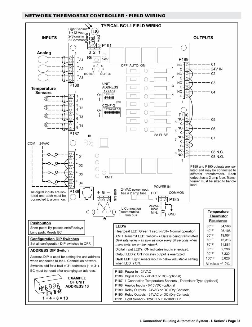
L Connection® Building Automation System - L Series® / Page 31
NETWORK THERMOSTAT CONTROLLER - FIELD WIRING
LED’sHeartbeat LED: Green 1 sec. on/off= Normal operationXMIT Transmit LED: Yellow - = Data is being transmittedBlink rate varies - as slow as once every 30 seconds whenmany units are on the networkDigital Input LED’s: ON indicates inut is energized.Output LED’s: ON indicates output is energized.Dark LED: Light sensor input is below adjustable settingwhen LED is ON.
NOC
NOC
NOCC
NCNO
5
6
7
8
T1
T2
T3
T4
TYPICAL BC1-1 FIELD WIRING
A1
A2
A3
+-+-+-
P188
P187
P186
P189
P190
12345678
+-+-+-+-
D1
D2
D3
D4
NOC
NOC
NOC
NOC
1
2
3
4
HOT COMMON
POWER IN
0124V IN02
03
04
05
06
07
08 N.C.08 N.O.
COM 24VAC
P189 and P190 outputs are iso-lated and may be connected todifferent transformers. Eachoutput has a 2 amp fuse. Trans-former must be sized to handleload.
24VAC power inputhas a 2 amp fuse.All digital inputs are iso-
lated and each must beconnected to a common. P185
P185 Power In - 24VACP186 Digital Inputs - 24VAC or DC (optional)P187 L Connection Temperature Sensors - Thermistor Type (optional)P188 Analog Inputs - 0-10VDC (optionalP189 Relay Outputs - 24VAC or DC (Dry Contacts)P190 Relay Outputs - 24VAC or DC (Dry Contacts)P191 Light Sensor - 12VDC out, 0-10VDC in.
1
1
1
1
1
1
XMIT
HB
INPUTS OUTPUTS
23 1
LSLight Sensor:1-+12 Vout2-Signal in3-Common
P191
Analog
TemperatureSensors
Red
Bla
ckYe
l
SW1
UNITADDRESS
ON1 2 4 8 16
ON 1 2 3 4 5 6 7 8CONFIG
OFF AUTO ON
2A FUSE
1 72 63 4 5
DARKER LIGHTER
R6 DARK
PushbuttonShort push: By-passes on/off delaysLong push: Resets BC
ADDRESS DIP SwitchAddress DIP is used for setting the unit addresswhen connected to the L Connection network.Switches add for a total of 31 addresses (1 to 31).BC must be reset after changing an address.
EXAMPLEOF UNIT
ADDRESS 13
1 + 4 + 8 = 134 8 1621
Temperature ThermistorResistance
30°F 34,566 40°F 26,106 50°F 19,904 60°F 15,313 70°F 11,884 80°F 9,298 90°F 7,332100°F 5,826All values +/- 2%.
Configuration DIP SwitchesSet all configuration DIP switches to OFF.
L Connectioncommunica-
tion bus GND
24VAC10VAMIN.

L Connection® Building Automation System - L Series® / Page 32
SYSTEM COMPONENTS - ZONING / NETWORK EXPANDER
The Zone Link has two important functions. It controls the unit for zoning applications based on the demands of up to 31 zones and it also can be used as a network expander, which expands the L Connection Network up to 93 units on one Network Control Panel.The Zone Link has a heartbeat LED and transmit LEDs on both communication ports for quick operation indication. It has two air balance modes that are set by a DIP switch that makes zoning air balance simple. Most applications will only require wiring to the Zone Link communication ports, but it also has 2 multi-functional digital inputs and 2 multi-functional outputs. The Zone Link is designed so that it can be mounted either inside a rooftop unit or inside the conditioned space. Power is provided from an external 24VAC transformer.
Main Features of the Zone Link• Automatically self configures for either zoning mode or
single zone expander mode.• 181 optional control parameters (ECTOs).
• Capable of controlling up to 31 zones/unit. Variable Air Volume Bypass (VAV) units.
• Constant Air Volume Bypass units (CAVB) w/bypass damper.
• Capable of adding up to 36 additional devices to network in bus expander mode.
• May be mounted in rooftop unit or in mechanical / electrical room of building.
• Built-in zoning air balance test mode.• 2 multi-functional 24VAC digital inputs.
• Time Clock Option.• Global Smoke Alarm for all units under Zone Link• Purge (Zoning only).• Global shutdown (Zoning only).
• 2 multi-functional digital (relay) outputs based on one of following conditions when used for zoning:• CO2 above setpoint.• RH above setpoint.• RH below setpoint.• Unit lockout condition.• Unit in occupied mode.
• 3 options for zoning demand control ventilation • Maximum occupied zone.• Average of all occupied zones.• Average of all zones.
• 3 zoning morning ventilation modes1. Air Mix.2. Fresh Air.3. Purge.
• LED indicators for both COM ports.• LED for Heartbeat.• Field upgradeable flash memory.• Screw terminals for field wiring.• Off-white plastic enclosure.• Bracket for RTU mounting included.
ZONE LINK C0CTRL11AE1L (11W27)

L Connection® Building Automation System - L Series® / Page 33
SYSTEM COMPONENTS - ZONING
ZONE LINK (CONTINUED)
Sequence of OperationMultiple Zones (Zone Link Zoning Mode)
COM - Lennox COM cable.Tstat - 2 conductor for damper only,5 conductor for fan powered w/heat.
Single Zone (Zone Link Network Expander Mode)
All cables shown are Lennox COM cable.24VAC power wiring not shown.
After power up , the Zone Link begins automatically polling from address 1 to 31 and searching for units (devices). As soon as a unit controller (IMC or Network Thermostat Controller) replies, the Zone Link checks the unit controller’s system mode. If the system mode is set to Remote Demand Mode, the Zone Link knows it’s a zoning application. Next, the Zone Link polls for Comfort Sensor-Zoning units. Now the Zone Link knows the application is zoning and how many zones are in use.If a Network Control Panel is connected to the network, the setpoints for each zone are sent from the Panel. If the Zone Link is setup in the time clock mode, the built-in default setpoints in the Zone Link will be sent to each Comfort Sensor-Zoning.Each Comfort Sensor-Zoning generates a vote for heating, cooling or no vote. The Zone Link adds up the votes of all zones, considering the zone weights and zone wait time of each zone and sends the appropriate heat/cool demand to the unit controller (IMC or Network Thermostat Controller). The demand is maintained as long as the voting result maintains the majority or the maximum changeover time is reached.
ZONE LINK (CONTINUED)
In single zone operation, the Zone Link powers up and begins automatically polling addresses 1 to 31, searching for units (devices). As soon as a unit controller (IMC or Network Thermostat Controller) replies, the Zone Link checks the unit controller’s system mode. If the system mode is anything except Remote Demand Mode, the Zone Link knows its application is not for zoning, but for single zone operation. Next, the Zone Link polls for a Comfort Sensor with the same address as the IMC or Network Thermostat Controller. If found, that Comfort Sensor is assigned to that particular unit. The Zone Link repeats this polling process until all units (devices) are found. The Zone Link can support up to 31 units without Comfort Sensors or 16 units paired with Comfort Sensors. If a Network Control Panel is connected to the network, the setpoints for each zone are sent from the Panel. If the Zone Link is setup in the time clock mode, the built-in default setpoints in the Zone Link will be sent to each Comfort Sensor-Zoning.There is no voting with single zone operation. The setpoints of the Comfort Sensor match the unit controller (IMC or Network Thermostat Controller) and Network Control Panel (or time clock).

L Connection® Building Automation System - L Series® / Page 34
SPECIFICATIONS - ZONE LINK Unit Controller Compatibility Zoning Applications
IMC - Version 5.02 or higher Network Thermostat Controller - Version 1.10 or higherBus Expander ApplicationsIMC - Version 3.03 or higher Network Thermostat Controller - All versions Building Controller - All versions
Network Control Panel Compatibility All Applications Unit Controller PC Software Compatibility Version 2.08 or higherNetwork Control Panel PC Software Compatibility
Version 2.08 or higher
Device Commissioning Auto-poll (real plug and play) Operating Environment Temperature: -40°F to 155°F
Humidity: 10% - 95% RH, Non- CondensingMemory Type Re-programmable FlashElectronic Configure To Order Parameters 181Power Requirements 24VAC (+/–25%), 50/60Hz, 2VA
Class 2 transformer requiredIndicator LEDs 1 - Heartbeat
1 - SysBus Transmit1 - ZoneBus Receive1 - Each for 2 digital inputs 1 - Each for 2 digital outputs
Dimensions Height: 5 in.Width: 8 in. Depth: 1-3/4 in.
Weight 0.46 lbs.Enclosure High impact ABS off-white plastic case.INPUTS / OUTPUTS Bus Port Lennox SysBus, EIA-485, 9600 baud
(Field wiring terminal block and phone jack located on side of control)Lennox ZoneBus, EIA-485, 9600 baud
Digital Inputs 1 and 2 - Multi-Functional - 24VAC inputs that can be configured based on one of the following operations: Time Clock, Purge (Zoning only), Shutdown (Zoning only), Global Smoke for units under Zone Link
Digital Outputs 1 and 2 - Multi-Functional - Relay (2 Amps, 24VAC) outputs that can be configured based on one of the following conditions for zoning; CO2 above setpoint, RH above setpoint , RH below setpoint , Unit Lockout, Unit occupied
Cable Type SysBus - Lennox yellow COMM cable: C0MISC00AE1- (27M19) (500 ft. box), C0MISC04AE1- (94L63) (1000 ft. box), C0MISC01AE1- (68M25) (2500 ft. roll)ZoneBus - Lennox purple COMM cable: C0MISC05AE1- (23W99) (500 ft. box) C0MISC06AE1- (24W00) (1000 ft. box) C0MISC07AE1- (24W01) (2500 ft. roll)24VAC Power - 2 Conductor thermostat 22 AWG min. (wire gauge depends on distance from transformer) Multi-functional I/O - Thermostat cable 22 AWG min.

L Connection® Building Automation System - L Series® / Page 35
ZONE LINK - FIELD WIRING
TO 24VAC(Polarity
Sensitive)TO SYSBUSNETWORK ZONEBUS
NETWORKYellow LennoxComm Cable
Purple LennoxComm Cable
ZONEBUSRECEIVE LED
SYSTEM BUSTRANSMIT LED
ZONE LINKHEARTBEAT
LED
SW1 DIPSWITCH
BlackRed
BlackRed
Com24VAC
OPTIONAL INPUTAND OUTPUT
TERMINAL BLOCK
PRESS TAB TOREMOVE COVER
SHIELDSHIELD

L Connection® Building Automation System - L Series® / Page 36
SYSTEM COMPONENTS - SENSORS
The Comfort Sensor is a communicating, single zone unit room temperature sensor that is available with optional built-in relative humidity and CO2 sensors. It is also available with LCD display with setpoint and fan control. Each model of the Comfort Sensor has an input for up to four additional optional remote room temperature sensors. These sensors may be used for applications that require remote temperature sensing or temperature averaging. In addition, each version also has an input for optional occupancy switch that could be used for controlling the occupied status of the unit as well as the occupied/unoccupied temperature setpoints. Each model can be used with the Network Control Panel for scheduling setpoints or in a stand-alone mode without the Network Control Panel. No setpoint scheduling is available when used in the stand-alone mode.Main Features of the Comfort Sensor
• Single unit temperature setpoint control.• Works with the Network Control Panel.• Also works in stand-alone mode.
• Available with zone RH and/or zone CO2 sensors.• CO2 self calibration system eliminates the need for
manual calibration in most applications.• Available with or without display and setpoint
adjustment.• Easy user interface on models with setpoint control.• Field upgradeable flash memory.• Display in degrees °F or °C.• May use up to four additional averaging sensors
(optional). • May use remote sensor (optional).• May use optional field provided occupancy sensor.• Screw terminals for field wiring.• Off-white plastic enclosure.• 8 Electronic Configure-To-Order (ECTO) parameters.• All models have after-hours override push-button.• All models have convenient phone jack for configuration
with L Connection Unit Controller PC software.
Models With Display and Setpoint Adjustment• C0SNAJ02AE1L (18W68) - Temperature, Display,
Setpoint/Fan Control, After-Hours Override Button• C0SNMT10AE1L (18W66) - Temperature, Relative
Humidity, Display, Setpoint/Fan Control, After-Hours Override Button
• C0SNMT20AE1L (18W67) - Temperature, CO2, Display, Setpoint/Fan Control, After-Hours Override Button
• C0SNMT30AE1L (18W65) - Temperature, Relative Humidity, CO2, Display, Setpoint/Fan Control, After-Hours Override ButtonUser InterfaceDisplay/Setpoint Adjustable Models have a user interface, consisting of an LCD display and three push buttons.Push button functions:1. Adjusting zone temperature setpoints.2. Changing zone occupied mode.3. Resuming a scheduled program.4. Viewing zone data, zone temperature (°F or °C),
relative humidity (%) , carbon dioxide level (PPM) and outdoor temperature (°F or °C).
5. Controlling unit blower.All models have an after-hours override button on the right side.
COMFORT SENSOR

L Connection® Building Automation System - L Series® / Page 37
COMFORT SENSOR (CONTINUED)
Display Options (Models With Display and Setpoint Adjustment)The information display on the Comfort Sensor’s main screen is configurable using Electronic Configure To Order (ECTO) parameters. The default configuration displays Indoor (zone) Temperature, Operation Status (HEAT or COOL), and Occupancy Status. The Indoor (zone) Temperature and Heating/Cooling Setpoints can be set to display in 0.5 degree increments (default is one degree).Depending on the type of Comfort Sensor model used, various other data can be displayed on the main screen:
• CO2 Models - Can be configured to display CO2 or Outdoor Temperature (You can access the mode not displayed by holding down the select button, the display will alternate between each mode at one second intervals).
• Relative Humidity (RH) Models - May be configured to display Relative Humidity or Heating Setpoint. If Relative Humidity is displayed, pushing any button will display Heating Setpoint.
• CO2 and Relative Humidity (RH) Models - Displays CO2 or Outdoor Temperature (You can access the mode not displayed by holding down the select button, the display will alternate between each mode at one second intervals). This model can also be configured to display Relative Humidity or Heating Setpoint. If Relative Humidity is displayed, pushing any button will display Heating Setpoint.
1.
5Zone
Temperature
7Degrees °F or °C
2Heating Setpoint orRelative Humidity
1Cooling Setpoint or
Zone Damper Position(Comfort Sensor -
Zoning only) 8Outdoor Temperature
or CO2 level10
Fan Status(CS only) 9
Occupancy Status
4Override
Mode3
ResumeProgram
6Operation
Status
Cooling Setpoint or Zone Damper Position - When the ECTO is set to display the damper position, any button may be pushed to display the setpoints. Damper position is available for use with Comfort Sensor-Zoning sensors only.
2. Heating Setpoint or Relative Humidity - When the ECTO is set to display the relative humidity, any button may be pushed to display the setpoints. Comfort Sensor/Comfort Sensor-Zoning must be equipped with RH option to display RH.
3. Resume Program - Displayed when override mode is returning to a scheduled program.4. Override Mode - Displayed when a scheduled program has been overridden. Also referred to as After-Hours
Override.5. Zone Temperature6. Operation Status - Either HEAT or COOL will be displayed when the zone is operating in heating or cooling mode.
The appropriate readout will blink if the zone is requesting either heating or cooling and the zone is not yet being serviced.
7. Degrees °C or °F8. Outdoor Temperature or CO2 - CO2 level shown in parts per million. The Comfort Sensor/Comfort Sensor-Zoning
must be equipped with CO2 option to display CO2.9. Occupancy Status - Displayed when the zone is in occupied mode. Nothing is displayed in this area during the
unoccupied time period.10. Fan Status - Comfort Sensor only. If enabled, the unit fan control status is displayed, either FAN ON (continuous)
or FAN AUTO (cycles with heating or cooling operation).
Models Without Display or Setpoint Adjustment• C0SNZN09AE1- (18W72) Temperature, After-Hours Override Button.• C0SNMT11AE1- (18W69) Temperature, Relative Humidity, After-
Hours Override Button.• C0SNMT21AE1L (18W70) - Temperature, CO2, After-Hours Override
Button.• C0SNMT31AE1L (18W71) - Temperature, Relative Humidity, CO2,
After-Hours Override Button.

L Connection® Building Automation System - L Series® / Page 38
SYSTEM COMPONENTS - SENSORS
COMFORT SENSOR (CONTINUED)
Sequence of OperationTemperature Setpoint and Occupancy Operation with Network Control Panel
The Comfort Sensor operates to maintain the zone temperature setpoint. The heating and cooling setpoints originate from a Zone Link running in Time Clock mode, a Network Control Panel or the Comfort Sensor. In applications using the Network Control Panel operating in manual mode, a Comfort Sensor with display can fully adjust the setpoints between a minimum of 40°F and the maximum of 95°F.The system maintains two sets of setpoints, Occupied and Unoccupied. If the zone is currently unoccupied, the zone may be overridden into the occupied state by:1. Pressing the UP/DOWN buttons to change the
current setpoints, in a display version of Comfort Sensor.
2. Pressing the OVERRIDE button on the side of the Comfort Sensor.
3. Applying an occupied signal to the Comfort Sensor Occupancy Input.
4. Changing the occupied state of the zone, at the Network Control Panel or using the Network Control Panel Software.
The Comfort Sensor with display can be used to override the current setpoints within a specified range. This range is set in an internal ECTO parameter.
A setting of zero disables this feature. Pressing the UP or DOWN buttons will change the current (most-recently serviced) heating or cooling setpoint. Pressing the SELECT button will highlight the other heating or cooling setpoint, allowing adjustment of this setpoint. These override setpoints will be active for the time specified in the Override Timer ECTO parameter that is set in the Network Control Panel.Pressing the side OVERRIDE button will initiate the override timer. The zone will go into the occupied state and use the override setpoints for the time set in the Override Timer ECTO parameter that is in the Network Control Panel.The override operation may be disabled by setting the Network Control Panel override timer ECTO parameter to zero.

L Connection® Building Automation System - L Series® / Page 39
SYSTEM COMPONENTS - SENSORS
COMFORT SENSOR (CONTINUED)
Sequence of OperationTemperature Setpoint and Occupancy Operation without Network Control Panel
The Comfort Sensor operates to maintain the zone temperature setpoint. In applications without a Network Control Panel, the heating and cooling setpoints originate from the IMC ECTO parameters. A Comfort Sensor model with display can be used to adjust the setpoints within its allowable range. The allowable range can be set from ± 0 to 10°F.Relative Humidity OperationThe Comfort Sensor models with built-in RH sensor can be used to control Humiditrol™ units based on the RH setpoint and conditions stored in the IMC unit controller ECTO parameters. The Comfort Sensor with RH sensor option can also be used to control any premium Lennox rooftop unit configured in supermarket reheat mode, which uses gas heat for reheat. Like Humiditrol operation, the RH setpoint and conditions for supermarket reheat are stored in the IMC unit controller ECTO parameters.
CO2 OperationThe Comfort Sensor models with built-in CO2 sensor can be used to control Lennox’ premium rooftop unit Demand Control Ventilation features based on CO2 setpoints and conditions stored in the IMC unit controller ECTO parameters.

L Connection® Building Automation System - L Series® / Page 40
SPECIFICATIONS - COMFORT SENSOR Unit Controller Compatibility IMC - Version 5.02 or higher
Network Thermostat Controller - Version 1.10 or higherNetwork Control Panel Compatibility Version 2.00 or higherUnit Controller PC Software Compatibility Version 2.08 or higherNetwork Control Panel PC Software Compatibility
Version 2.08 or higher
Device Commissioning Auto-poll (real plug and play) Operating Environment Temperature: -0°F to 105°F
Humidity: 10% - 95% RH, Non- CondensingMemory Type Re-programmable FlashElectronic Configure To Order Parameters 8Power Requirements 24VAC (+/-25%), 50/60Hz, 3VA
Class 2 transformer requiredTemperature Range Temperature: –33°F to 99°FTemperature Accuracy +/- 0.4°F (May be field calibrated to +/- 0.25°F) RH Range 10-95% RHRH Accuracy +/- 5% RH (May be field calibrated to +/-2%) CO2 Range 0-2000 ppm CO2 Accuracy +/- 40 ppm + 3% or reading @ 25C
CO2 sensor has built-in self calibration algorithm Unit Controller PC software can be used to turn the self calibration algorithm off, set elevation and to calibrate sensor if needed.
Temperature Setpoint Range Temperature: -40°F to 95°FDisplay Type (for models w/displays) Liquid Crystal (LCD) with Green LED backlight Dimensions Height: 5 in.
Width: 4-1/2 in. Depth: 1-3/8 in.
Weight 0.42 lbs.Enclosure High impact ABS off-white plastic case.INPUTS / OUTPUTSBus Port: Lennox SysBus, EIA-485, 9600 baud (Field wiring terminal block and phone
jack located on side of control). Note - May connect to ZoneBus if under Zone Link.
Remote Temperature Sensor Input Up to four remote temperature sensors connected in parallel for averaging and remote monitoring. Compatible with Miniature Wall-Mount Zone Sensor C0SNZN08AE1- (94L61) and Wall-Mount Zone Sensor with Adjustable Zone Temperature C0SNAJ01AE1- (56L80).
Occupancy Sensor Input 24VAC input (On for occupied) Cable Type SysBus - Lennox yellow COMM cable:
C0MISC00AE1- (27M19) (500 ft. box), C0MISC04AE1- (94L63) (1000 ft. box), C0MISC01AE1- (68M25) (2500 ft. roll) ZoneBus - Lennox purple COMM cable: C0MISC05AE1- (23W99) (500 ft. box) C0MISC06AE1- (24W00) (1000 ft. box) C0MISC07AE1- (24W01) (2500 ft. roll)24VAC Power - Two Conductor thermostat 22 AWG min. (wire gauge depends on distance from transformer) Remote Temperature Sensor - Two Conductor thermostat cable 22 AWG min. (wire gauge depends on distance) Occupancy Sensor - Two Conductor thermostat cable 22 AWG min. (wire gauge depends on distance.

L Connection® Building Automation System - L Series® / Page 41
COMFORT SENSOR - FIELD WIRING
A76Comfort Sensor (CS)
401215S

L Connection® Building Automation System - L Series® / Page 42
SYSTEM COMPONENTS - SENSORS
The Comfort Sensor-Zoning is a communicating zone temperature sensor and controller that is available with a variety of features including built-in relative humidity and CO2 sensors. It is also available with or without LCD display and setpoint adjustment. Each model of the Comfort Sensor-Zoning also has outputs necessary to control either a zone damper or a fan powered VAV terminal with electric heat.Each model has an input for up to four additional optional remote room temperature sensors. These sensors may be used for applications that require remote temperature or temperature averaging. In addition, each model has an input for an optional occupancy switch that can be used for controlling the occupied status of the zone as well as the occupied/unoccupied temperature setpoints.The Comfort Sensor-Zoning must be used in conjunction with a Zone Link for controlling the unit in zoning applications. In addition, the Network Control Panel can be used for scheduling up to six setpoint changes per day for each zone. A time clock may be used for controlling the occupied status of the zones as well as the occupied/unoccupied temperature setpoints.Main Features of the Comfort Sensor-Zoning
• Zone sensor and zoning controller for damper, fan and zone heat.
• Compatible with Damper Actuator C0MISC21AE1L (12W98).
• Available with zone RH and/or zone CO2 sensors• Available with or without display. Units with display have
setpoint control.• Easy user interface on models with setpoint control• Field upgradeable flash memory.• Display in degrees °F or °C.• May use up to four additional averaging sensors
(optional).• May use remote sensor (optional).• May use optional field provided occupancy sensor.• 28 Electronic Configure To Order (ECTO) parameters• Screw terminals for field wiring.• Off-white plastic enclosure.• All models have after-hours override push-button.• All models have convenient phone jack for configuration
with L Connection Unit Controller PC software.
Models With Display and Setpoint Adjustment• C0SNCT01AE1L (18W58) - Temperature, Display,
Setpoint/Fan Control, After-Hours Override Button, Zone Damper, Fan and Heat Control.
• C0SNCT10AE1L (18W56) - Temperature, Relative Humidity, Display, Setpoint/Fan Control, After-Hours Override Button, Zone Damper, Fan and Heat Control.
• C0SNCT20AE1L (18W57) - Temperature, CO2, Display, Setpoint/Fan Control, After-Hours Override Button, Zone Damper, Fan and Heat Control.
• C0SNCT30AE1L (18W55) - Temperature, Relative Humidity, CO2, Display, Setpoint/Fan Control, After-Hours Override Button, Zone Damper, Fan and Heat Control.
Models Without Display or Setpoint Adjustment
• C0SNCT00AE1L (18W59) - Temperature, After-Hours Override Button, Zone Damper, Fan and Heat Control
• C0SNCT11AE1L (18W60) - Temperature, Relative Humidity, After-Hours Override Button, Zone Damper, Fan and Heat Control
• C0SNCT21AE1L (18W61) - Temperature, CO2, After-Hours Override Button, Zone Damper, Fan and Heat Control
• C0SNCT31AE1L (18W62) - Temperature, Relative Humidity, CO2, After-Hours Override Button, Zone Damper, Fan and Heat Control
COMFORT SENSOR-ZONING

L Connection® Building Automation System - L Series® / Page 43
SYSTEM COMPONENTS - SENSORS
COMFORT SENSOR-ZONING (CONTINUED)
Sequence of OperationSetpoint and Occupancy OperationThe Comfort Sensor-Zoning operates to maintain the zone temperature setpoint. The heating and cooling setpoints originate from the Zone Link operating in time clock mode, or a Network Control Panel running a time schedule program. In a Network Control Panel application operating in manual mode, a Comfort Sensor-Zoning with a display can be used to fully adjust the setpoints between a minimum of 40°F and the maximum of 95°F.The system maintains two sets of setpoints, Occupied and Unoccupied.If the zone is currently unoccupied, the zone may be overridden into the occupied state by:1. Pressing the UP/DOWN buttons to change the current setpoints, in a display version of the Comfort Sensor-Zoning2. Pressing the OVERRIDE button on the side of the Comfort Sensor-Zoning.3. Applying an occupied signal to the Comfort Sensor-Zoning occupancy input.4. Changing the occupied state of the zone, at the Network Control Panel or using the Network Control Panel
Software.The Comfort Sensor-Zoning with display can be used to override current setpoints within a specified range. This range is set using an ECTO parameter. A setting of zero disables this feature. Pressing the UP or DOWN buttons will change the current (most-recently serviced) heating or cooling setpoint. Pressing the SELECT button will highlight the other setpoint, allowing the adjustment of this setpoint. These override setpoints will be active for the time specified in the Override Timer ECTO parameter that is set in the Network Control Panel.Pressing the OVERRIDE button on the right side of the case will initiate the override timer. The zone will go into the occupied state, and use the override setpoints for the time set in the Override Timer ECTO parameter that is in the Zone Link.The override operation may be disabled by setting the Zone Link Override Timer ECTO parameter to zero.The application of 24 volts AC to the occupancy sensor input of the Comfort Sensor-Zoning will force the zone into the occupied state. The Comfort Sensor-Zoning will operate with occupied setpoints as long as this signal is applied.Heating and Cooling Demands and Zone Damper OperationThe Comfort Sensor-Zoning will generate a cooling demand if the zone temperature is a specified amount above the cooling setpoint. This amount is set in the ECTO parameter, COOLING DIFFERENTIAL 1. The default is 0.5 °F. The cooling demand will remain until the zone temperature drops below the temperature defined by: COOLING SETPOINT plus COOLING DIFFERENTIAL 1, minus ECTO parameter COOLING DEADBAND (default 1.5°F).A high demand cooling state is entered if the zone temperature exceeds the setpoint plus ECTO parameter, COOLING DIFFERENTIAL 2. This higher demand state will, by default, double the weight of the cooling demand to the Zone Link in determining the operating state of the HVAC unit.Similarly, the Comfort Sensor -Zoning will generate a heating demand if the zone temperature is a specified amount below the heating setpoint. This amount is set in the ECTO parameter, HEATING DIFFERENTIAL 1. The default is 0.5 °F. The heating demand will remain until the zone temperature rises above the temperature defined by: HEATING SETPOINT minus HEATING DIFFERENTIAL 1, plus ECTO parameter HEATING DEADBAND (default 1.5°F).A high demand heating state is entered if the zone temperature is lower than the setpoint minus ECTO parameter, HEATING DIFFERENTIAL 2. This higher demand state will, by default, double the weight of the heating demand to the Zone Link in determining the operating state of the HVAC unit.If the zone is in a heating or cooling demand and the supply air is not suitable for this demand, the zone damper will be at its minimum position if the zone is occupied, or closed if the zone is unoccupied.If there is no demand but the supply air temperature is above the cooling setpoint or below the heating setpoint, the zone damper will be at its minimum position if the zone is occupied, or closed if the zone is unoccupied.If the supply air is suitable for the demand, the Comfort Sensor-Zoning will modulate the damper according to a proportional-integral (PI) control algorithm, the zone temperature and the temperature setpoint. There is an ECTO parameter for the proportional constant and for the integral constant for each of the heating and cooling demands.If the zone temperature is between the heating and cooling setpoints, the supply air is between the setpoints and the zone is occupied, the damper will open to the ECTO parameter ventilation position.

L Connection® Building Automation System - L Series® / Page 44
SYSTEM COMPONENTS - SENSORS
COMFORT SENSOR-ZONING-continued
Sequence of Operation (Continued)Zone Terminal Box OperationThe Comfort Sensor-Zoning can optionally control a zone terminal box. It has one relay output for controlling either a series or parallel fan, and one relay output to control either electric reheat, auxiliary heat, or peripheral heat.With a zone terminal box, the zone has the opportunity for local heat operation, while the HVAC unit is either idle or is in cooling.A series fan pulls air from both the supply air duct and the return air plenum. It is on whenever the zone is occupied, or is in either heating, local heating, cooling or ventilation states.A parallel fan pulls air from the return air plenum. It is on only during the local heating state.Electric reheat is on with either a low or high demand, during a local heat state. It requires air flow from either the terminal box fan, or the HVAC unit blower with the zone damper set to the ventilation position.Auxiliary heat is on with a high demand, during a local heat state. It requires either the terminal box fan or the HVAC unit blower to be on.Peripheral heat is on with any heat demand - either a local heat state or when the HVAC unit is heating.Zone High CO2 OperationThe Comfort Sensor-Zoning may be configured to open the zone damper to the ventilation position and turn on the zone terminal box fan if the zone carbon dioxide level exceeds a specified CO2 setpoint. The zone will stay in this state until the CO2 level is 100 ppm lower than the CO2 setpoint.The Comfort Sensor-Zoning default setting for this feature is disabled.When the Comfort Sensor-Zoning is in the High CO2 state, the zone quits voting to determine the demands to the HVAC unit. The zone temperature is still used in determining the discharge air temperature reset, if enabled.The Comfort Sensor-Zoning CO2 setpoint must be set higher than the HVAC unit IAQ setpoint.Other Modes of OperationSmoke Mode - The Comfort Sensor-Zoning monitors the status of the HVAC unit. If the HVAC unit is in smoke mode, then the Comfort Sensor-Zoning will also go to smoke mode. If the unit’s blower is running in smoke mode, Comfort Sensor-Zoning will turn on its series fan and open the zone damper to ventilation position. Otherwise the Comfort Sensor-Zoning will close the zone damper and turn off the terminal box fan.The zone damper and terminal box fan may be controlled remotely by the Zone Link or though the Unit Controller Software when the system is in a special mode such as air balance or building air purge.

L Connection® Building Automation System - L Series® / Page 45
SPECIFICATIONS - COMFORT SENSOR-ZONING Unit Controller Compatibility IMC - Version 5.02 or higher
Network Thermostat Controller - Version 1.10 or higherNetwork Control Panel Compatibility Version 2.00 or higherZone Link Compatibility Version 1.00 or higherUnit Controller PC Software Compatibility Version 2.08 or higherNetwork Control Panel PC Software Compatibility
Version 2.08 or higher
Device Commissioning Auto-poll (real plug and play) Operating Environment Temperature: -0°F to 105°F
Humidity: 10% - 95% RH, Non- CondensingMemory Type Re-programmable FlashElectronic Configure To Order Parameters 28Power Requirements 24VAC (+/-25%), 50/60Hz, 3VA
Class 2 transformer requiredTemperature Range Temperature: -34°F to 99°FTemperature Accuracy +/- 0.4°F (May be field calibrated to +/- 0.25°F) RH Range 5-95% RHRH Accuracy +/- 5% RH (May be field calibrated to +/-2%) CO2 Range 0-2000 ppm CO2 Accuracy +/- 40 ppm + 3% of reading @ 77°F
CO2 sensor has built-in self calibration algorithm Unit Controller PC software can be used to turn the self calibration algorithm off, set elevation and to calibrate sensor if needed.
Temperature Setpoint Range Temperature: -40°F to 95°FDisplay Type (for models w/displays) Liquid Crystal (LCD) with Green LED backlight Dimensions Height: 5 in.
Width: 1/2 in. Depth: 1-3/8 in.
Weight 0.44 lbs.Enclosure High impact ABS off-white plastic case.INPUTS / OUTPUTSBus Port Lennox SysBus, EIA-485, 9600 baudRemote Temperature Sensor Input Up to four remote temperature sensors connected in parallel for averaging with
the internal sensor or for remote monitoring. Compatible with Miniature Wall-Mount Zone Sensor C0SNZN08AE1- (94L61) and Wall-Mount Zone Sensor with Adjustable Zone Temperature C0SNAJ01AE1- (56L80).
Occupancy Sensor Input 24VAC input (On for occupied) Zone Damper Output 2-10VDC (modulating damper)Zone Damper Feedback Input 2-10VDC input - not used on Damper Actuator C0MISC21AE1L (12W98)Zone Fan Output Relay (24VAC, 1 Amp ) Zone Heat Output Relay (24VAC, 1 Amp) Cable Type ZoneBus - Lennox purple COMM cable:
C0MISC05AE1- (23W99) (500 ft. box) C0MISC06AE1- (24W00) (1000 ft. box) C0MISC07AE1- (24W01) (2500 ft. roll)24VAC Power - Two Conductor thermostat 22 AWG min. (wire gauge depends on distance from transformer) Remote Temperature Sensor - Two Conductor thermostat cable 22 AWG min. (wire gauge depends on distance) Occupancy Sensor - Two Conductor thermostat cable 22 AWG min. (wire gauge depends on distance) Zone Damper Output - Thermostat cable 22 AWG min. (wire gauge depends on distance)Zone Damper Feedback - Thermostat cable 22 AWG min. (wire gauge depends on distance)Zone Fan Output - Thermostat cable 20 AWG min. (wire gauge depends on distance)Zone Heat Output - Thermostat cable 20 AWG min. (wire gauge depends on distance)

L Connection® Building Automation System - L Series® / Page 46
COMFORT SENSOR - FIELD WIRING
A8Comfort Sensor−Zoning(CSZ)

L Connection® Building Automation System - L Series® / Page 47
SYSTEM COMPONENTS - SENSORS
Two-wire non-communicating wall-mounted zone sensors. Each sensor is designed to fit a single gang electrical handy box. The C0SNAJ01AE1- has a sensor offset slide that allows for easy temperature adjustment. Each sensor also has SysBus/ZoneBus phone jack that may be connected to the network. The bus connection is not required for sensor operation.Main Features of Non-Communicating Zone Sensors
• Terminal blocks for wiring connections.• Simple two-wire sensor connection. • After-hours override button.• Off-white plastic enclosure.• C0SNAJ01AE1- features warmer/cooler zone
adjustment on bottom of sensor • Provides +/- zone temperature offset control.
• Adjustment amount is field selected using a DIP switch located under the cover.Options include:
• +/- 1°F. • +/- 4°F. • Non-adjustable.
• Sensor has a phone jack that may be used for connecting a PC converter to a PC with L Connection Network software.
• Sensor does not require a connection to the L Connection Network to function.
• C0SNZN07AE1- does not have the warmer/cooler temperature adjustment feature.
ZONE SENSOR - WALL-MOUNT (NON-COMMUNICATING) C0SNAJ01AE1- (56L80) AND C0SNZN07AE1- (94L60)
SPECIFICATIONS - Zone SENSOR (NON-COMMUNICATING)Unit Controller Compatibility IMC, Network Thermostat ControllerTemperature Range 40°F to 95°FOffset Adjustment Range (C0SNAJ01AE1- only)
DIP switch options (located under cover) 1. No adjustment 2. +/- 1°F 3. +/- 4°F
Accuracy +/-0.36°FStability +/-0.23°FInterchangeability +/-0.36°FSensor Type NTC thermistor , 11K @76°F w/offset Pot Enclosure High impact ABS off-white plastic caseDimensions Height: 4-1/2 in.
Width: 2-3/4 in.Depth: 1-1/8 in.
Weight 0.0625 lbs.INPUTS / OUTPUTSSensor Two-wire (not polarity sensitive) SysBus/ZoneBus Optional (polarity sensitive) Cable Type Optional SysBus - Lennox yellow COMM cable:
C0MISC00AE1- (27M19) (500 ft. box), C0MISC04AE1- (94L63) (1000 ft. box), C0MISC01AE1- (68M25) (2500 ft. roll)

L Connection® Building Automation System - L Series® / Page 48
SYSTEM COMPONENTS - SENSORS
Small non-communicating wall-mount zone sensors.• C0SNZN08AE1- Non-communicating only• C0SNZN03AE1- Non-communicating for use with
Building Controller
Main Features of Non-Communicating Zone Sensors
• Small size.• Terminal block for wiring connections.• Off-white plastic enclosure.• C0SNZN03AE1- for use with the Building Controller.
MINIATURE ZONE SENSOR - WALL-MOUNT (NON-COMMUNICATING) C0SNZN08AE1- (94L61) AND C0SNZN03AE1- (59M04)
SPECIFICATIONS - MINIATURE ZONE SENSOR (NON-COMMUNICATING)Unit Controller Compatibility C0SNZN08AE1- IMC, Network Thermostat Controller
C0SNZN03AE1- Building ControllerTemperature Range 40°F to 95°FAccuracy +/-0.36°FStability +/-0.23°FInterchangeability +/-0.36°FSensor Type C0SNZN08AE1- NTC thermistor, 11K @76°F
C0SNZN03AE1- NTC thermistor, 10K @76°F Enclosure High impact ABS off-white plastic case with aluminum baseDimensions Height: 1-1/2 in.
Width: 2 in.Depth: 1 in.
Weight 0. 06 lbs.Cable Type Sensor - Lennox yellow COMM cable:
C0MISC00AE1- (27M19) (500 ft. box), C0MISC04AE1- (94L63) (1000 ft. box), C0MISC01AE1- (68M25) (2500 ft. roll)

L Connection® Building Automation System - L Series® / Page 49
SYSTEM COMPONENTS - SENSORS
Duct mounted non-communicating zone sensor designed for applications where a wall mounted sensor is not practical. The sensor wires directly to the unit controller zone sensor input.
Main Features of Non-Communicating Zone Sensors
• 12 in. probe with mounting plate.• Stainless steel construction.
RETURN AIR DUCT MOUNT ZONE SENSOR (NON-COMMUNICATING) C0SNDC02AE1- (56L81)
SPECIFICATIONS - RETURN AIR DUCT MOUNT ZONE SENSOR (NON-COMMUNICATING)Unit Controller Compatibility IMC, Network Thermostat ControllerTemperature Range 40°F to 95°FAccuracy +/-0.36°FStability +/-0.23°FInterchangeability +/-0.36°FSensor Type NTC thermistor , 11K @76°F Mounting Mounting plate for 2 screwsDimensions Length: 12 in.
Diameter: 1/4 in.Weight 0.0625 lbs.Cable Type Sensor - Lennox yellow COMM cable:
C0MISC00AE1- (27M19) (500 ft. box), C0MISC04AE1- (94L63) (1000 ft. box), C0MISC01AE1- (68M25) (2500 ft. roll)

L Connection® Building Automation System - L Series® / Page 50
SYSTEM COMPONENTS - SENSORS
Two small wall-mounted non-communicating zone sensors that are used for averaging zone temperatures in two locations. These sensors MUST be used together.
Main Features of Averaging Zone Sensor Kit• Kit includes two wall-mounted sensors.• Terminal block for wiring connections.• Wired in parallel for simple installation.• Off-white plastic enclosure.
AVERAGING ZONE SENSOR KIT - WALL-MOUNT (NON-COMMUNICATING) C0SNZN71AE1- (23M20)
SPECIFICATIONS - AVERAGING ZONE SENSOR KIT (NON-COMMUNICATING)Unit Controller Compatibility IMC, Network Thermostat ControllerTemperature Range 40°F to 95°FAccuracy +/-0.36°F (+/-0.2C) Stability +/-0.23°F (+/-0.13C)Interchangeability +/-0.36°F (+/-0.2C) Sensor Type NTC thermistor , 22K @76°F (Each Sensor) Must be connected in parallel Enclosure High impact ABS off-white plastic case.Dimensions (Each Sensor) Height: 1-1/2 in.
Width: 2 in.Depth: 1 in.
Weight 0.12 lbs.Cable Type Sensor - Lennox yellow COMM cable:
C0MISC00AE1- (27M19) (500 ft. box), C0MISC04AE1- (94L63) (1000 ft. box), C0MISC01AE1- (68M25) (2500 ft. roll)

L Connection® Building Automation System - L Series® / Page 51
SYSTEM COMPONENTS - SENSORS
Non-communicating flush wall-mount zone sensor. Sensor fits a single gang electrical handy box. For applications that require flush mounted wall sensors.
Main Features of Flush Zone Sensor• Single gang electrical handy box size.• Stainless steel wall mounting plate.• Simple two-wire sensor connection.
ZONE SENSOR - FLUSH WALL-MOUNT (NON-COMMUNICATING) C0SNZN04AE1- (76M32)
SPECIFICATIONS - ZONE SENSOR - FLUSH WALL-MOUNT (NON-COMMUNICATING)Unit Controller Compatibility IMC, Network Thermostat ControllerTemperature Range 40°F to 95°FAccuracy +/-0.36°FStability +/-0.23°FInterchangeability +/-0.36°FSensor Type NTC thermistor , 11K @76°FCover Material Stainless steelDimensions (Each Sensor) Height: 4-1/2 in.
Width: 2-3/4 in.Depth: 1/8 in.
Weight 0.4 lbs.Cable Type Sensor - Lennox yellow COMM cable:
C0MISC00AE1- (27M19) (500 ft. box), C0MISC04AE1- (94L63) (1000 ft. box), C0MISC01AE1- (68M25) (2500 ft. roll)

L Connection® Building Automation System - L Series® / Page 52
SYSTEM COMPONENTS - SENSORS
Wall mounted non-communicating CO2 sensors.Sensors may be used for demand control ventilation.
Main Features of CO2 Sensors• C0SNSR52AE1L - Off-white plastic cover, no display. • C0SNSR50AE1L - Off-white plastic cover with LCD
display.• C0SNSR53AE1L - Black plastic case, no display,
UL94-5V rated, may be used in return air duct.• C0SNSR51AE1L - Black plastic case, LCD display,
UL94-5V rated, may be used in return air duct.All Models
• Plug and play compatible with the IMC Integrated Unit Controller on Lennox’ premium units.
• Patented absorption infrared gas sensing engine.• Self-calibration system eliminates the need for manual
calibration in most applications.• Gas permeable, water resistant CO2 diffusion filter
prevents particulate and water contamination of the sensor
• Screw type terminal blocks.• +/- 40 ppm + 3% of reading up to 1000 ppm
+/- 40 ppm + 5% of reading up to 1000-1200 ppm +/- 40 ppm + 7% of reading up to 1200-2000 ppm
• Dual outputs (0-10VDC and 4-20mA).
CO2 SENSOR - WALL-MOUNT (NON-COMMUNICATING) C0SNSR52AE1L (87N53), C0SNSR50AE1L (77N39), C0SNSR53AE1L (87N54), C0SNSR51AE1L (87N52)

L Connection® Building Automation System - L Series® / Page 53
SPECIFICATIONS - CO2 SENSORS - WALL-MOUNT (NON-COMMUNICATING)Controller Compatibility IMC Integrated Unit Controller, Building Controller, Network Thermostat
ControllerPower Requirements 24VAC (+/–25%), 50/60Hz, 2VA maximumOperating Conditions 32-122°F
0-95% RH, non-condensingMeasurement Range 400-2000 ppm (0 ppm=0 V, 4mA)Output Range (Dual) 0-10VDC and 4-20mAAccuracy +/- 40 ppm + 3% of reading up to 1000 ppm
+/- 40 ppm + 5% of reading up to 1000-1200 ppm +/- 40 ppm + 7% of reading up to 1200-2000 ppm ABC (Automatic Background Calibration) Logic self-calibration system.
Measuring Method Non-dispersive infrared (NDIR) absorptionTemperature Sensor Type NTC 10 KΩ thermistor, with 1 KΩ offset in seriesThermistor Accuracy ±1.8° (59 to 95°F) Display C0SNSR52AE1L, C0SNSR53AE1L - none
C0SNSR50AE1L, C0SNSR51AE1L - LCD type display w/coverEnclosure C0SNSR50AE1L, C0SNSR52AE1L - High impact ABS off-white plastic case.
C0SNSR51AE1L, C0SNSR53AE1L - High impact ABS black plastic case. UL94-5V rated. (May be used in return duct)
Dimensions Height: 4-1/2 in.Width: 3-3/16 in.Depth: 1-1/16 in.
Weight 0.5 lbs.INPUTS / OUTPUTSAnalog Outputs 1- 0-10VDC (100 Ω output impedance)
1- 4-20mA (RL maximum 500 Ω) (Output not used for Lennox controllers)Temperature Sensor Two-wire (not polarity sensitive)Cable Type Wire runs under 50 ft.
2 twisted pair shielded cable (2 Lennox yellow COMM cables): C0MISC00AE1- (27M19) (500 ft. box), C0MISC04AE1- (94L63) (1000 ft. box), C0MISC01AE1- (68M25) (2500 ft. roll)Wire runs over 50 ft. but under 150 ft. 2 twisted pair shielded cable (18 AWG) Wire runs over 150 ft. Requires local isolated power transformer: C0MISC30AE1- (18M13), 24VAC, 20VA maximum 1 twisted pair shielded cable (1 Lennox yellow COMM cable): C0MISC00AE1- (27M19) (500 ft. box), C0MISC04AE1- (94L63) (1000 ft. box), C0MISC01AE1- (68M25) (2500 ft. roll)
ACCESSORYDownflow Duct Mounting Kit C0MISC19AE1- (85L43) - Allows installation of CO2 sensor in return air
opening of packaged rooftop units in downflow applications
CO2 SENSOR - FIELD WIRING
outputs
IAQ+
M1 M2CONTROLLER
SMA
RTW
IRE
24VAC
SENSOR TERMINAL BLOCK
power
8
7
5
4
15
10
2
1
AC−
AC+
7
6
16
17
TMPTHERM+
THERM−
VCO2
COM
TB1 P298
C
R
NOT CONNECTED
TWISTED PAIR
NOT CONNECTED
TWISTED PAIR
TWISTED PAIR
AC Power 3-Wire System
ISOLATED 24VTRANSFORMER
outputs
IAQ+
M1 M2CONTROLLER
SMA
RTW
IRETB
1
SENSOR TERMINAL BLOCK
power
8
7
5
4
15
10
2
1
AC−
AC+
16
17
NOT CONNECTED
TWISTED PAIR
TMPTHERM+
THERM−
VCO2
COM
TB1 P298
NOT CONNECTED
TWISTED PAIR
NOT CONNECTED
TWISTED PAIR
Isolated AC Power 4-Wire Syatem

L Connection® Building Automation System - L Series® / Page 54
SYSTEM COMPONENTS - CO2 SENSOR ACCESSORIES
Converts standard wall mount CO2 sensors to duct mount applications. The custom internal mounting bracket secures the base of the sensor inside the aspiration box. Power is applied by running conduit through a knockout and wiring to the terminal blocks located on the sensor mounting bracket. The enclosure is lightweight, durable, and can be installed in minutes.
Main Features of CO2 Sensor Duct Mount Aspiration Box
• See-through cover.• Custom mounting bracket.• Duct sample tube.• Choice of knockouts.
CO2 SENSOR DUCT MOUNT ASPIRATION BOX C0MISC16AE1- (90N43)
SPECIFICATIONS - CO2 SENSOR DUCT MOUNT ASPIRATION BOXSensor Compatibility Wall mount models - C0SNSR52AE1L (87N53), C0SNSR50AE1L (77N39)Electrical Knockouts 7/8 in., 1-1/8 in. and 1-1/16 in. Enclosure Material ABS plasticMinimum Air Flow 400 fpmDimensions Height: 7 in.
Width: 4-1/4 in. Depth: 3-1/2 in.
Sample Probe Size Length: 7.00 in. Diameter: 1.125 in.
Weight 2 lbs.

L Connection® Building Automation System - L Series® / Page 55
SYSTEM COMPONENTS - SENSORS
Non-communicating wall mounted RH sensor. Sensor fits a single gang electrical handy box. Sensor may be used for Humiditrol® units or units that use the IMC Supermarket reheat feature.
Main Features of Remote Relative Humidity Sensor• Terminal blocks for wiring connections. • Relative humidity range: 0 -100%.• +/- 3% Accuracy.• Off-white plastic enclosure.
REMOTE RELATIVE HUMIDITY SENSOR - WALL-MOUNT (NON-COMMUNICATING) C0SNSR31AE1- (17M50)
SPECIFICATIONS - REMOTE RELATIVE HUMIDITY SENSOR - WALL-MOUNTController Compatibility IMC, Building Controller, Network Thermostat ControllerOperating Environment Temperature: –10°F to 160°F
Humidity: 0-95% RH, non-condensingPower Requirements 24VAC, +/- 25%, 50/60Hz, 1.5 VARH Range 5-95%Accuracy +/-3% RH from 20 to 95% RH @77°FEnclosure High impact ABS off-white plastic caseDimensions Height: 4-1/2 in.
Width: 2-3/4 in.Depth: 1-1/8 in.
Weight 0.3 lbs.INPUTS / OUTPUTSAnalog Output 0-10VDC, 0-5VDC or 4-20mA
(0-10VDC is used for IMC, Building Controller and Network Thermostat Controller) Cable Type Wire runs under 50 ft.
2 twisted pair shielded cable (2 Lennox yellow COMM cables): C0MISC00AE1- (27M19) (500 ft. box), C0MISC04AE1- (94L63) (1000 ft. box), C0MISC01AE1- (68M25) (2500 ft. roll)Wire runs over 50 ft. but under 150 ft. 2 twisted pair shielded cable (18 AWG) Wire runs over 150 ft. Requires local isolated power transformer: C0MISC30AE1- (18M13), 24VAC, 20VA maximum 1 twisted pair shielded cable (1 Lennox yellow COMM cable): C0MISC00AE1- (27M19) (500 ft. box), C0MISC04AE1- (94L63) (1000 ft. box), C0MISC01AE1- (68M25) (2500 ft. roll)

L Connection® Building Automation System - L Series® / Page 56
SYSTEM COMPONENTS - SENSORS
Non-communicating return air duct mounted RH sensor designed for applications that require mounting the sensor in the return air duct. Sensor may be used for Humiditrol® units or units that use the IMC Supermarket reheat feature.
Main Features of Return Air Duct Relative Humidity Sensor
• Terminal blocks for wiring connections.• Relative humidity range: 0 -100%.
RETURN AIR DUCT RELATIVE HUMIDITY SENSOR (NON-|COMMUNICATING) C0SNSR30AE1- (76M31)
SPECIFICATIONS - RETURN AIR DUCT RELATIVE HUMIDITY SENSORController Compatibility IMC, Building Controller, Network Thermostat ControllerOperating Environment Temperature: –10°F to 160°F
Humidity: 0-95% RH, non-condensingPower Requirements 24VAC (+/–25%), 50/60Hz, 1.5 VA RH Range 5-95%Accuracy +/-3% RH from 20 to 95% RH @77°FEnclosure High impact ABS off-white plastic caseDimensions: Electronics Enclosure: 4 in. dia x 2-1/4 in.
Duct Probe: 7-7/8 in. x 3/4 in. diameter Weight 1 lbs.INPUTS / OUTPUTSAnalog Output 0-10VDC, 0-5VDC or 4-20mA
(0-10VDC is used for IMC, Building Controller and Network Thermostat Controller) Cable Type Wire runs under 50 ft.
2 twisted pair shielded cable (2 Lennox yellow COMM cables): C0MISC00AE1- (27M19) (500 ft. box), C0MISC04AE1- (94L63) (1000 ft. box), C0MISC01AE1- (68M25) (2500 ft. roll)Wire runs over 50 ft. but under 150 ft. 2 twisted pair shielded cable (18 AWG) Wire runs over 150 ft. Requires local isolated power transformer: C0MISC30AE1- (18M13), 24VAC, 20VA maximum 1 twisted pair shielded cable (1 Lennox yellow COMM cable): C0MISC00AE1- (27M19) (500 ft. box), C0MISC04AE1- (94L63) (1000 ft. box), C0MISC01AE1- (68M25) (2500 ft. roll)

L Connection® Building Automation System - L Series® / Page 57
SYSTEM COMPONENTS - SENSORS
The Remote Discharge Temperature Sensor Kit is for applications that use the IMC Discharge Air Control or Fresh Air Tempering feature available in all Lennox’ premium rooftop units. This kit replaces the discharge
air temperature sensor that is standard in these units. The kit includes a Duct Temperature Sensor C0SNDC04AE1- (99K64) and 15 ft. of cable.
REMOTE DISCHARGE TEMPERATURE SENSOR KIT C0SNDC03AE1- (45L78)
SPECIFICATIONS - REMOTE DISCHARGE TEMPERATURE SENSOR KITController Compatibility IMC, Network Thermostat ControllerAccuracy +/-0.36°FStability +/-0.23°FInterchangeability +/-0.36°FSensor Type NTC thermistor , 10K @76°F Mounting Mounting plate for 2 screws (Duct Mount) Dimensions Length: 12 in.
Diameter: 1/4 in.Weight 0.0625 lbs.Cable Included 2 - 18AWG 105C wire (15 ft.)

L Connection® Building Automation System - L Series® / Page 58
SYSTEM COMPONENTS - SENSORS
The Outdoor Air Control Sensor Kit is an air velocity sensor that can be used on Lennox’ premium rooftop units. The kit also includes a wiring harness, mounting bracket and includes an Integrated Modular Controller IMC I/O Module Kit C0CTRL01AE1L (86M39).
Main Features of Outdoor Air Control Sensor Kit• Three field selectable air velocity ranges.• Includes Integrated Modular Controller I/O Module
Kit C0CTRL01AE1L (86M39).• Innovative hot film anemometer principle.
The sensor is used for modulating the economizer (outdoor air damper) to hold the outside air flow rate constant. The sensor may also be used with the Building Controller for monitoring air flow and setting alarms or controlling digital outputs.
OUTDOOR AIR CONTROL SENSOR KIT C0SNSR23DE1- (98M61)
SPECIFICATIONS - OUTDOOR AIR CONTROL SENSOR KITController Compatibility Integrated Modular Controller - Version 5.02 or higher
Building ControllerOperating Environment Temperature: 14°F to 122°FPower Requirements 24VAC (+/-25%), 50/60Hz, 3.6VA maximumAir Flow Ranges 0 to 984 ft./min. (Adjustable by jumpers)
0 to 1480 ft./min. (Adjustable by jumpers) 0 to 1970 ft./min. (Adjustable by jumpers)
Accuracy +/- 0.5 ft./sec +3% (for 0 to 984 ft./min. range) +/- 1 ft./sec +3% (for 0 to 1480 ft./min. range) +/- 1 ft./sec +4% (for 0 to 1970 ft./min. range)
Response Time 4 sec. or 0.2 sec. (Adjustable by jumpers)Electrical Connections Screw terminal block Output 0-10VDC, 4-20mA (Adjustable by jumpers)Dimensions (electronics) Height: 3-1/8 in.
Width: 3-1/8 in.Depth: 1-1/2 in.
Dimensions (probe) 8 length x 1/2 in. diameterEnclosure Polycarbonate NEMA 4Weight 0.5 lbs.Cable Type 2 - Lennox yellow COMM cables:
C0MISC00AE1- (27M19) (500 ft. box), C0MISC04AE1- (94L63) (1000 ft. box), C0MISC01AE1- (68M25) (2500 ft. roll)
NOTE - See the Integrated Modular Controller I/O Module Kit on 21 for specifications.
OUTDOOR AIR CONTROL SENSOR KIT - FIELD WIRING
V+ =GND =
AV =
supplyvoltagegroundairflowoutput
V+GND
AV
123
+
−~
~
V/m A
powersupply24 V AC/DC± 10%

L Connection® Building Automation System - L Series® / Page 59
SYSTEM COMPONENTS - SENSORS
Outdoor temperature sensor used primarily with the Building Controller and Network Thermostat Controller. It has a water-proof plastic wiring enclosure. The temperature sensor is surrounded by a vented aluminum enclosure to reduce the effect of wind and sunlight on the temperature measurement.
Main Features of Outdoor Temperature Sensor• Water-proof wiring junction box with conduit
knockouts.• Vented aluminum cover around sensor.• Compatible with the Building Controller and the
Network Thermostat Controller.
OUTDOOR TEMPERATURE SENSOR C0SNSR02AE1- (59M05)
SPECIFICATIONS - OUTDOOR TEMPERATURE SENSORController Compatibility Building Controller, Network Thermostat ControllerAccuracy +/-0.36°FStability +/-0.23°FInterchangeability +/-0.36°FSensor Type NTC thermistor , 10K @76°F Dimensions Width: 4 in.
Height: 6-3/4 in.Depth: 2-1/4 in.
Enclosure Water-proof plastic junction box (White) Weight 0.4 lbs.Cable Type Sensor - Lennox yellow COMM cable:
C0MISC00AE1- (27M19) (500 ft. box), C0MISC04AE1- (94L63) (1000 ft. box), C0MISC01AE1- (68M25) (2500 ft. roll)

L Connection® Building Automation System - L Series® / Page 60
SYSTEM COMPONENTS - SENSORS
When used with Network Thermostat Controller applications, the Duct Temperature Sensor displays the return air temperature on the Network Control Panel and software program display screens. This sensor will act as a backup in case the zone sensor has a wiring problem or malfunctions. It will also allow the use of the return air limit option.
Building Controller ApplicationsWhen used with Building Controller applications, the sensor can be used to display the temperature at the Network Control Panel and software program display screens. It can also be used to override an output.
DUCT TEMPERATURE SENSOR C0SNDC04AE1- (99K64)
SPECIFICATIONS - DUCT TEMPERATURE SENSORController Compatibility IMC, Building Controller, Network Thermostat ControllerAccuracy +/-0.36°FStability +/-0.23°FInterchangeability +/-0.36°FSensor Type NTC thermistor , 10K @76°F Mounting Mounting plate for 2 screwsDimensions Length: 12 in.
Diameter: 1/4 in.Weight 0.0625 lbs.Cable Type Sensor - Lennox yellow COMM cable:
C0MISC00AE1- (27M19) (500 ft. box), C0MISC04AE1- (94L63) (1000 ft. box), C0MISC01AE1- (68M25) (2500 ft. roll)

L Connection® Building Automation System - L Series® / Page 61
SYSTEM COMPONENTS - SENSORS
When used with Network Thermostat Controller applications, the Temperature Sensor Probe displays the return air temperature on the Network Control Panel and software program display screens. It can also be used as a general purpose sensor to monitor refrigerated coolers, ice makers, etc. The sensor also allows the low ambient compressor control option and allows use of the heat pump supplemental heat lockout option that keeps the supplemental heat off if outside air temperature is above the selected set-point.
TEMPERATURE SENSOR PROBE C0SNSR05AE1- (14K92)
Building Controller ApplicationsWhen used with Building Controller applications, the sensor can be used to display the temperature at the Network Control Panel and software program display screens
SPECIFICATIONS - TEMPERATURE SENSOR PROBEController Compatibility IMC, Building Controller, Network Thermostat ControllerAccuracy +/-0.36°FStability +/-0.23°FInterchangeability +/-0.36°FSensor Type NTC thermistor , 10K @76°F Mounting Mounting plate for 2 screwsDimensions Length: 3 in.
Diameter: 1/4 in.Weight 0.06 lbs.Cable Type Sensor - Lennox yellow COMM cable:
C0MISC00AE1- (27M19) (500 ft. box), C0MISC04AE1- (94L63) (1000 ft. box), C0MISC01AE1- (68M25) (2500 ft. roll)

L Connection® Building Automation System - L Series® / Page 62
SYSTEM COMPONENTS - SENSORS
The Supply Static Differential Pressure Sensor has three operating ranges and three output options.
Main Features of Supply Static Pressure Sensor• Pre-set to 0 - 5.0 in. w.c. range and 0-10VDC output.• Additional ranges and outputs are available by hanging
mini-jumpers.• NIST traceable calibration.• Compatible with IMC and Network Thermostat
Controller Bypass Controller.
SUPPLY STATIC DIFFERENTIAL PRESSURE SENSOR C0SNSR20AE1 (78M19)
SPECIFICATIONS - SUPPLY STATIC DIFFERENTIAL PRESSURE SENSORController Compatibility Integrated Modular Controller - Version 5.01 or higher
Building Controller Network Thermostat Controller Bypass Controller
Operating Environment 0 to 175°F 10 to 90% RH
Compensated Temperature Range 25 to 150°FPower Requirements 24VAC (+/-25%), 50/60Hz, 0.5VA maximumOperating pressure range 0 - 5 in. w.c., 0 - 2.5 in. w.c., 0 -1.25 in. w.c. (adjustable)
Factory Setting: 0 - 5 in. w.c. Accuracy +/- 1% F.S.Overpressure 10 PSIDOutput 0-10VDC, 0-5VDC, 4-20mA
Factory setting - 0-10VDCMedia Compatibility Clean dry air or any inert gasTermination Un-pluggable screw terminal block Enclosure Steel NEMA 4, aluminum probeDimensions Height: 6 in.
Width: 4 in. (with mounting tabs)Depth: -2-1/4 in.Probe length: 8 in.
Weight 1 lbs.Cable Type Wire runs under 50 ft.
2 twisted pair shielded cable (2 Lennox yellow COMM cables): C0MISC00AE1- (27M19) (500 ft. box), C0MISC04AE1- (94L63) (1000 ft. box), C0MISC01AE1- (68M25) (2500 ft. roll)Wire runs over 50 ft. but under 150 ft. 2 twisted pair shielded cable (18 AWG) Wire runs over 150 ft. Requires local isolated power transformer: C0MISC30AE1- (18M13), 24VAC, 20VA maximum 1 twisted pair shielded cable (1 Lennox yellow COMM cable): C0MISC00AE1- (27M19) (500 ft. box), C0MISC04AE1- (94L63) (1000 ft. box), C0MISC01AE1- (68M25) (2500 ft. roll)

L Connection® Building Automation System - L Series® / Page 63
SUPPLY STATIC DIFFERENTIAL PRESSURE SENSOR - FIELD WIRING

L Connection® Building Automation System - L Series® / Page 64
SYSTEM COMPONENTS - SENSORS
The Return (Building) Static Differential Pressure Sensor has three operating ranges and three output options. It is used with optional power exhaust fans to control building static pressure on Lennox’ premium rooftop units (IMC).
Main Features of Building Static Pressure Sensor• Pre-set to -0.5 to 0.5 in. w.c. range and 0 to 10VDC
output for IMC.• Additional ranges and outputs are available by
changing mini-jumpers.• Compatible with IMC.• C0SNSR22AE1- (79M21) Outdoor Air Weather Head
required for reducing outdoor static pressure fluctuations.
RETURN (BUILDING) STATIC DIFFERENTIAL PRESSURE SENSOR C0SNSR21AE1- (78M20)
SPECIFICATIONS - BUILDING (RETURN) STATIC DIFFERENTIAL PRESSURE SENSORController Compatibility Integrated Modular Controller - Version 5.01 or higher
Building ControllerOperating Temperature 0 to 175°F
10 to 90% RHCompensated Temperature Range 25 to 150°FPower Requirements 24VAC (+/-25%), 50/60Hz, 0.5VA maximumOperating Range 0 - 1.0 in. w.c., 0 - 0.5 in. w.c., 0 - 0.25 in. w.c.,
-0.5 - 0.5 in. w.c., -0.25 - 0.25 in. w.c., -0.125 - 0.125 in. w.c.Factory Setting is -0.5-+0.5 in. w.c.
Accuracy +/- 1% F.S.Overpressure 10 PSIDOutput 0-10VDC, 0-5VDC, 4-20mA
Factory Settings is 0-10VDCEnclosure Steel NEMA 4, aluminum probeMedia Compatibility Clean dry air or any inert gasTermination Un-pluggable screw terminal block Dimensions Height: 6 in.
Width: 4 in. (with mounting tabs)Depth: 2-1/4 in.
Weight 1 lbs.Cable Type Wire runs under 50 ft.
2 twisted pair shielded cable (2 Lennox yellow COMM cables): C0MISC00AE1- (27M19) (500 ft. box), C0MISC04AE1- (94L63) (1000 ft. box), C0MISC01AE1- (68M25) (2500 ft. roll)Wire runs over 50 ft. but under 150 ft. 2 twisted pair shielded cable (18 AWG) Wire runs over 150 ft. Requires local isolated power transformer: C0MISC30AE1- (18M13), 24VAC, 20VA maximum 1 twisted pair shielded cable (1 Lennox yellow COMM cable): C0MISC00AE1- (27M19) (500 ft. box), C0MISC04AE1- (94L63) (1000 ft. box), C0MISC01AE1- (68M25) (2500 ft. roll)

L Connection® Building Automation System - L Series® / Page 65
SUPPLY STATIC DIFFERENTIAL PRESSURE SENSOR - FIELD WIRING
High
High
Low
Low
EnclosureMount
+ − 0+ − 0
Z SZ S
PanelMount
(VDC output)
LegendS = Span AdjustZ = Zero Adjust+ = Supply Voltage (Hot)– = Common (Neutral)
(VDC output)

L Connection® Building Automation System - L Series® / Page 66
SYSTEM COMPONENTS - SENSORS
SYSTEM COMPONENTS - SENSORS
Main Features of Ambient Light Sensor• Monitors wide range of light.• Linear output voltage.• Electronics encased in a clear epoxy and sealed with
an electronic grade non-corrosive urethane resin.
AMBIENT LIGHT SENSOR C0SNSR60AE1- (34M67)
Outdoor ambient light sensor for use with the Building Controller and Network Control Panel for automatic lighting control.
SPECIFICATIONS - AMBIENT LIGHT SENSORController Compatibility Building ControllerOperating Power 12VDC (provided by Building Controller) Output Voltage 0-10VDCLight Sensor Range 0 - 15 FCDimensions (diameter x length) 1-1/4 x 2-9/16 in.Enclosure White PVC plastic case. Electronics encased in a clear epoxy and sealed with an
electronic grade, non-corrosive urethane resin. Mounting Mounts to a standard threaded 1/2 in. conduit or 1/2 in. knockout.Weight 1 lbs.Cable Type 3-conductor thermostat cable , 18 AWG min.

L Connection® Building Automation System - L Series® / Page 67
SYSTEM COMPONENTS - NETWORK
galvanic isolation. The signal (reference) ground for both EIA-485 ports float with respect to power supply ground. Jumpers enable 120 ohm internal terminating and bias resistors. 500 watt voltage transient suppressor diodes protect the Network Repeater from normal mode surges, while the full galvanic isolation protects it from common mode surges.Main Features of the Network Repeater
• 2.5kV optical isolation.• Doubles the permitted network cable length.• Operates up to 115k baud.• DIN rail mounting.
NETWORK REPEATER C0CTRL51AE1L (11W30)
The Network Repeater connects two-wire EIA-485 devices and networks together without danger of ground loops and damaging surges. It also doubles permitted cable length. Data signals have 2.5kV optical isolation. Isolated DC supplies provide full three-port
SPECIFICATIONS - NETWORK REPEATEROperating Environment Temperature: -40°F to 149°F
Humidity: 10% - 95% RH, Non- CondensingPower Requirements 5V DC +/- 5%
9V to 36V DC120VAC power supply included
Isolation (ISO/IEC 9549) EIA-485 to EIA-485 - 2500 V (optical, 5kV test) Supply to field - 2500 V (galvanic, 3kV test) Supply to local - 2-port = none ; 3-port = 2500V
Communications Max Speed - At least 115 Kbps over 500m Character Setting - transparent, no configuration required User Indications - Each receive signal has LED (yellow) Standard Distance - 4000 ft.
Case Material Nylon polymide, fungus and termite resistant, self-extinguishing, epoxy pottingMounting Rail DIN EN 50022 or 50035Dimensions Height: 3 in.
Width: 3 in. Depth: 1 in.
Weight 0.2 lbs .INPUTS / OUTPUTSEIA-485 Ports Signal Type : EIA-485A
Voltage Level : : -7 to +12 VDC Permitted Surge : +/- 25 VDC
Approvals UL - 873 Plenum rated Canadian UL - cUL C22.2 No. 24-93 CE - 89/336/ECC, 73/23/ECC C-Tick - N314
Cable Type SysBus - Lennox yellow COMM cable: C0MISC00AE1- (27M19) (500 ft. box), C0MISC04AE1- (94L63) (1000 ft. box), C0MISC01AE1- (68M25) (2500 ft. roll)ORZoneBus - Lennox purple COMM cable: C0MISC05AE1- (23W99) (500 ft. box) C0MISC06AE1- (24W00) (1000 ft. box) C0MISC07AE1- (24W01) (2500 ft. roll)Power - Cable provided with kit

L Connection® Building Automation System - L Series® / Page 68
NETWORK REPEATER - FIELD WIRING
SysBus or ZoneBus
GD−D+
GD−D+
TOP VIEW
−V +V
BlackRed
SysBus or ZoneBus
12VDC From Power Supply
BlackRed
Black Red

L Connection® Building Automation System - L Series® / Page 69
SYSTEM COMPONENTS - NETWORK
Main Features of the Surge Protector• Up to 20kA impulse discharge (8/20µs wave).• Self-resetting current limited to 250mA.• Simplifies ground wire installation.
SURGE PROTECTOR C0MISC92AE1- (23W22)
Protects two-wire EIA-485 circuits such as the Lennox SysBus or ZoneBus. Built-in self-resetting current limiters both eliminate the need for external fuses and protects from common continuous over-voltage faults.
SPECIFICATIONS - SURGE PROTECTOROperating Environment Temperature: -40°F to 149°F
Humidity: 10% - 95% RH, Non- CondensingNominal Operating Voltage +/-15V DCNominal Operating Current Less than 250mASeries Resistance 6.5 ohms @25CImpulse Discharge Current 20kA (wave form 8/20µs) Current Limit PTC device Course Protection Ceramic Gas Discharge TubeFine Protection High Speed Transient Suppressor DiodeCommunication Speed Range 300 to 115 KbpsCase Material Nylon polymide, fungus and termite resistant,
self-extinguishing, epoxy pottingMounting Rail DIN EN 50022 or 50035Dimensions Height: 3 in.
Width: 3 in. Depth: 1 in.
Weight 0.2 lbs.INPUTS / OUTPUTS Field Network - (D0+/Tx, Earth, DO-/Rx)
Equipment Network - (D1+/Tx, SGnd, D1-/Rx)Cable Type SysBus - Lennox yellow COMM cable:
C0MISC00AE1- (27M19) (500 ft. box), C0MISC04AE1- (94L63) (1000 ft. box), C0MISC01AE1- (68M25) (2500 ft. roll)ORZoneBus - Lennox purple COMM cable: C0MISC05AE1- (23W99) (500 ft. box) C0MISC06AE1- (24W00) (1000 ft. box) C0MISC07AE1- (24W01) (2500 ft. roll)Earth Ground - 18AWG minimum

L Connection® Building Automation System - L Series® / Page 70
SYSTEM COMPONENTS - NETWORK
Main Features of the Network to PC Converter• Required for direct (local) connection between the
L Connection (SysBus and ZoneBus) Network and a PC running L Connection Network PC software.
• Plugs directly into PC serial connector (9-pin).• Has phone jack and terminal block connector for
L Connection Network (SysBus and ZoneBus).• Data transmit and data receive LEDs.• No transformer required.• Self-powered through the PC.• Phone cord (15 ft.) for direct connection to any L
Connection Network device included.
NETWORK BUS TO PC CONVERTER KIT C0MISC47AE1- (96L78)
The Network to PC converter is an EIA-232 to Lennox SysBus and ZoneBus data converter. The converter is powered from the PC serial port. It has a 9-pin connector for the PC serial connection. It has two Lennox network connectors, a phone jack and a two-position screw terminal block.
SPECIFICATIONS - NETWORK BUS TO PC CONVERTEROperating Power Self-powered through PC serial portOperating Temperature 0°F to 120°FPC Connector (Serial Port) 9-pin, D-typeNetwork Bus Connectors 2 screw type terminal blocks
RJ9 type phone jack (handset type)Network Bus Indicators 2 red LEDs , data transmit and data receiveMaximum Network Bus Speed 38.4k baudDimensions Height: 1 in.
Width: 2-1/4 in.Depth: 2-3/4 in.
Weight 0.5 lbs.Cable Type L Connection phone cord (furnished) or Lennox yellow COMM cables:
C0MISC00AE1- (27M19) (500 ft. box), C0MISC04AE1- (94L63) (1000 ft. box), C0MISC01AE1- (68M25) (2500 ft. roll)

L Connection® Building Automation System - L Series® / Page 71
SYSTEM COMPONENTS - NETWORK
Main Features of Network Modem Kit• Connects phone line directly to L Connection Network
for remote access.• Specially programmed for the L Connection Network.• Network transmit, receive and connect LEDs.
NETWORK MODEM KIT C0MISC46AE1- (94L62)
The Network Modem Kit for the L Connection Network allows remote access to the network via the L Connection PC software. Kit includes phone modem, network modem converter, wall mount transformer and phone cable.
SPECIFICATIONS - NETWORK MODEM KITUnit Controller PC Software Compatibility All versionsNetwork Control Panel PC software Compatibility All versions Operating Power Wall-plug 120VAC transformer included.LED Indicators Phone Modem : AA- Auto Answer Mode, CD- Carrier Detect, RD- Received
Data, SD- Send Data,TR- Data Terminal Ready, CS-Clear To SendNetwork Modem Converter: Data Transmit, Data Receive
Dimensions Height: 1-1/2 in.Width: 6-5/8 in.Depth: 6-5/8 in. (with network modem converter)
Enclosure High impact ABS white or black plastic case.Weight 2 lbs.INPUTS / OUTPUTSConnections Network: 2-position screw terminal block
Phone: Phone Jack RJ11Cable Type Network Lennox yellow COMM cable:
C0MISC00AE1- (27M19) (500 ft. box), C0MISC04AE1- (94L63) (1000 ft. box), C0MISC01AE1- (68M25) (2500 ft. roll)Phone: Phone cable with plug (furnished)
Agency FCC approved (Part 15 Class B/Part 68) IC approved (ICES-003/CS-03) UL/ULC listed

L Connection® Building Automation System - L Series® / Page 72
SYSTEM COMPONENTS - NETWORK
Main Features of Phone Line Auto-Router• Allows Network Modem to share a phone line with a
phone and fax machine.• Uses security code to automatically route the incoming
call to the modem.• May be used to connect up to three modems on one
phone line.• No professional rewiring is required for use in single-
line businesses.• Complete compatibility with existing equipment and
easy to program.• “Caller ID” compatibility and silent transferring between
equipment.• “Power/Call Status” light, non-volatile memory that
saves programming in case of a power outage.• 120VAC transformer (wall-plug) included.
PHONE LINE AUTO-ROUTER C0MISC41AE1- (34M22)
The Phone Line Auto-Router is a telephone line sharing device that allows the L Connection modem to share a phone line with a phone and or fax machine.Automatically routes all voice, fax and modem calls to the right equipment - eliminating the need for costly dedicated phone lines.Programmed security code automatically routes the incoming calls to the modem.
SPECIFICATIONS - PHONE LINE AUTO-ROUTEROperating Power Wall-plug 120VAC transformer included.Dimensions Height: 2-1/2 in.
Width: 8-1/8 in. Depth: 1-1/2 in.
Enclosure High impact ABS white plastic case.Weight 5 lbs.INPUTS / OUTPUTSCable Type Phone cable with plug

L Connection® Building Automation System - L Series® / Page 73
SYSTEM COMPONENTS - NETWORK
ETHERNET CONVERTER KIT C0MISC43AE1L (76M77)
The Ethernet Converter Kit is required to interface between the L Connection Network and an Ethernet local area network (LAN). It allows the user to monitor and control devices on the L Connection Network from any PC on the LAN that has Network Control Panel PC Software or Unit Controller PC Software installed. If the user has access to the LAN from outside their firewall, they can also monitor and control the L Connection Network remotely via the Internet using the same software installed on their remote PC. LED indicators monitor traffic flow and diagnostics.Kit includes:
• Ethernet Converter.• 6 ft. Ethernet patch cable.• Modem converter.• Power transformer.NOTE - Network Control Panel PC Software or Unit
Controller PC Software must be ordered separately (version 2.05 or higher is required).
SPECIFICATIONS - ETHERNET CONVERTER KITUnit Controller PC Software Compatibility Version 2.05 or higherNetwork Control Panel PC Software Compatibility Version 2.05 or higherOperating Power 9 to 30VDC, 1VA maximum
115V transformer (wall-plug type) includedOperating Temperature 41°F to 122°FSerial Interface Lennox L Connection Network (EIA-485)
Connector: Screw Terminal Block (2)LAN Interface Ethernet 10Base-T/100Base-TX
Connector: RJ45Standards: TCP/IP and DHCP
LED Indicators 10 link/activity (green), 100 link/activity (green), collision (red), diagnostics (red), status (green)
Dimensions Height: 6-1/2 in.Width: 3-9/16 in.Depth: 1 in.
Enclosure Gray metal and gray plasticWeight 1 lbs.Cable Type Lennox yellow COMM cable for L Connection SysBus:
C0MISC00AE1- (27M19) (500 ft. box), C0MISC04AE1- (94L63) (1000 ft. box), C0MISC01AE1- (68M25) (2500 ft. roll)Ethernet patch cable (furnished)

L Connection® Building Automation System - L Series® / Page 74
SYSTEM COMPONENTS - NETWORK
SERVICE TUBE KIT (59W52)
1
2
3
4
5
6
7
8
Service Tube Kit contains components to service both legacy L Series® units and Energence® units via a laptop or PC. Since the connections differ on legacy units and today’s models, the Service Tube Kit is a comprehensive collection of all necessary adaptors and cables needed to connect to and service Lennox rooftop units.
Key Component Qty.1 Cobra USB adaptor, USB male to RS485 12 Flash Drive, 2GB 13 Flathead screwdriver 14 Cable with modular plug, 4 connector, 5 in. 2
5 Coiled cable assembly, modular plug at each end, 4 connector, 7 ft.
1
6 USB adaptor, A male A to B female 17 USB extension cable, A male to A female, 6 ft. 18 USB extension cable, A male to B male B, 6 ft. 1

L Connection® Building Automation System - L Series® / Page 75
SYSTEM COMPONENTS - NETWORK
C0MISC01AE1- (68M25) 2500 ft. roll
C0MISC07AE1- (24W01) 2500 ft. roll
L CONNECTION® SYSBUS NETWORK CABLE
L CONNECTION® ZONEBUS NETWORK CABLE
C0MISC00AE1- (27M19) 500 ft. boxC0MISC04AE1- (94L63) 1000 ft. box
C0MISC05AE1- (23W99) 500 ft. boxC0MISC06AE1- (24W00) 1000 ft. box
SPECIFICATIONS - SYSBUS NETWORK CABLEType Twisted pair 100% shielded communication cable
22 AWG, yellow jacket, rated at 75°C, 300V Plenum rated Insulation - Low smoke PVC NEC, CMP
Color Outside jacket- Yellow, with order number imprinted Twisted pair - Red and Black
Weight C0MISC00AE1- 8 lbs.
C0MISC04AE1- 14 lbs.
C0MISC01AE1- 30 lbs.Lengths C0MISC00AE1- (500 ft. box)
C0MISC04AE1- (1000 ft. box)C0MISC01AE1- (2500 ft. roll)

L Connection® Building Automation System - L Series® / Page 76
SYSTEM COMPONENTS - SOFTWARE
NETWORK CONTROL PANEL PC SOFTWARE C0SOFT11AE1 - (96L82)
The Network Control Panel PC Software is a Microsoft® Windows® based program for interfacing directly with the Network Control Panel through a personal computer.Features and benefits:
• Local access through a computer that is tied in directly to an L Connection Network via a serial COM port.• Remotely access the Network Control Panel through an L Connection Network Modem or Ethernet Converter.• Set-up the Network Control Panel settings and programs from a PC.• Can be used to set-up building schedules “off-line”.• Easily and quickly upload saved schedules at a later date.• Modify setpoints and monitor the status of each controller connected to the Network Control Panel.• View controller alarms stored in the Network Control Panel.• Displays unit operating mode including current zone temperature, heating and cooling setpoints, CO2 levels (optional
CO2 sensor required), humidity levels (optional sensor required), number of compressors, blower status, economizer status, filter status, and the number of heating and cooling stages.
• Displays status of the Building Controller including current status of each output, temperature sensor, digital inputs and analog inputs.
• Print and save reports that include schedules, controller alarms and status.• Alarm e-mail notification (Requires Network Control Panel PC Software to be running and connected to a
network and Microsoft Outlook installed and setup for e-mail).• Data logging and graphing (Requires Network Control Panel PC Software to be running and connected to a network
and Microsoft Excel to view data logging reports).Additional Equipment:
• Network Bus to PC Converter Kit C0MISC47AE1- (96L78) for direct (local) serial COM port connections.• Network Modem Kit C0MISC46AE1- (94L62) for remote dial-up connections.• Ethernet Converter Kit C0MISC43AE1L (76M77) for TCP/IP connections.
CD-ROM includes software and L Connection Network controls manuals.Computer system requirements: IBM compatible PC with Pentium® or higher processor, Microsoft® Windows® 95, 98, Me, 2000, XP, or NT®. (Windows® 95, Windows® 98, Windows® Me, Windows® 2000, Windows® XP, and Windows® NT® are registered trademarks of Microsoft Corp.), 256 MB RAM (more memory may be required to run additional applications simultaneously), requires at least 20 MB of free hard drive space, VGA or higher resolution monitor (screen resolution must be 800 X 600 or higher and 256 colors), CD-ROM drive, mouse or compatible pointing device, serial COM port, PC modem for remote connections.

L Connection® Building Automation System - L Series® / Page 77
SYSTEM COMPONENTS - Software
UNIT CONTROLLER PC SOFTWARE C0SOFT01AE1- (96L80)
The Unit Controller Software is a Microsoft® Windows® based PC program for interfacing directly with HVAC equipment.For Lennox’ premium rooftop units, the software will interface with the Integrated Modular Controller (IMC). For non-IMC Lennox units or third-party equipment including rooftop units and split systems, the software will interface with the Network Thermostat Controller DDC module.This software is required for the following:• Changes to the control parameters in the Network Thermostat Controller.• Changes to the control parameters in the Zone Link and Comfort Sensor.
This software will also interface to the Building Controller for configuring building functions and interfacing with the zoning network with Zone Link and Comfort Sensors.Features and Benefits:• Allows user the option to set-up, monitor, and diagnose rooftop units from their PC. • Allows the user to set-up or change the Electronic Configure to Order (ECTO) parameters, view alarm codes, view
unit status, test unit and print/save reports.Additional Equipment:• Network Bus to PC Converter Kit C0MISC47AE1- (96L78) for direct (local) serial COM port connections.• Network Modem Kit C0MISC46AE1- (94L62) for remote dial-up connections.• Ethernet Converter Kit C0MISC43AE1L (76M77) for TCP/IP connections.
CD-ROM includes software and L Connection Network controls manuals.Computer system requirements: IBM compatible PC with Pentium® or higher processor, Microsoft® Windows® 95, 98, Me, 2000, XP, or NT®. (Windows® 95, Windows® 98, Windows® Me, Windows® 2000, Windows® XP, and Windows® NT® are registered trademarks of Microsoft Corp.), 256 MB RAM (more memory may be required to run additional applications simultaneously), requires at least 20 MB of free hard drive space, VGA or higher resolution monitor (screen resolution must be 800 X 600 or higher and 256 colors), CD-ROM drive, mouse or compatible pointing device, serial COM port, PC modem for remote connections.

L Connection® Building Automation System - L Series® / Page 78
SYSTEM COMPONENTS - ZONING ACCESSORIES
NETWORK THERMOSTAT CONTROLLER - BYPASS CONTROLLER C0CTRL70AE1L (11W31)
Sequence of OperationThe Network Thermostat Controller Bypass Controller monitors the supply static pressure from the pressure sensor and compares that reading to the supply static pressure setpoints set by using the setpoint potentiometer or setpoint voltage. The controller modulates the bypass damper voltage output to control the unit’s supply static pressure based on the controller’s PI loop settings.
Network Thermostat Controller Bypass Controller is a proportional and integral (PI) setpoint controller used for controlling the bypass damper for units using the Network Thermostat Controller for CAVB zoning applications. All setup and programming is done by DIP switches and jumpers. Set points may be local and/or remote. The output may be direct- or reverse-acting.Main Features of Setpoint Controller
• Simple stand-alone operation.• PI setpoint control.• Setpoint potentiometer.• DIP switch/jumper programming.• Compatible with Damper Actuator C0MISC21AE1L
(12W98).• Compatible with Supply Static Differential Pressure
Sensor C0SNSR20AE1 (78M19).
SPECIFICATIONS - BYPASS CONTROLLEROperating Environment Temperature: 32° to 158°F
Humidity: 10% - 95% RH, Non-CondensingPower Requirements 24VAC (+/–10%), 50/60Hz, 3VA (Class 2 transformer required)Accuracy +/- 1%Dimensions Height: 4-5/8 in.
Width: 4-13/16 in.Depth: 2 in.
Weight 0.4 lbs.INPUTS / OUTPUTSLocal Set Point input 10K potentiometer Remote Set Point input 4-20mA, 1-5VDC or 10K potentiometerAnalog Output 4-20mA for controlling bypass damper actuator.
Compatible with Damper Actuator C0MISC21AE1L (12W98)Analog Inputs 1-5VDC for Duct Static Pressure Sensor.
Compatible with Supply Static Differential Pressure Sensor C0SNSR20AE1 (78M19)
Cable Type Analog Output - Two conductor thermostat cable 20AWG min.Analog Input - 2 twisted pair shielded cable (2 Lennox yellow COMM cables): C0MISC00AE1- (27M19) (500 ft. box), C0MISC04AE1- (94L63) (1000 ft. box), C0MISC01AE1- (68M25) (2500 ft. roll)

L Connection® Building Automation System - L Series® / Page 79
BYPASS CONTROLLER - FIELD WIRING

L Connection® Building Automation System - L Series® / Page 80
SYSTEM COMPONENTS - ZONING ACCESSORIES
DAMPER ACTUATOR C0MISC21AE1L (12W98)
Main Features of the Damper Actuator• Used for all damper sizes, both zone and unit bypass
dampers.• Used for all bypass dampers.• Mounts to Lennox dampers with one screw.• Provided with 2-10VDC and 4-20mA control inputs.• Screw field wiring terminal block.
The Damper Actuator is used for zone damper and bypass damper control. The modulating actuator is controlled by a 2-10VDC or 4-20mA input. The actuator requires 24VAC for power.
SPECIFICATIONS - DAMPER ACTUATORUnit Controller Compatibility Integrated Modular Controller - Version 5.01 or higher
(requires optional IMC VAV Module Kit)Units Without Integrated Modular Controller (IMC)
Network Thermostat Controller Bypass Controller required
Operating Environment Temperature: 20° to 125°FHumidity: 10% - 95% RH, non- condensing
Power Requirements 24VAC (+/–20%), 50/60Hz, 4.8VA (class 2 transformer required)Torque 35 in./lbs.Stroke Selectable 45°, 60° and 90°Rotation Clockwise and counter-clockwiseStroke Time 90 Seconds for 90°Dimensions Height: 4-7/8 in.
Width: 3-3/8 in. Depth: 2-7/8 in
Weight 1.6 lbs.INPUTS / OUTPUTSAnalog Inputs 2-20VDC
4-20mA Approvals UL: 873 Plenum rated
Canadian UL: cUL C22.2 No. 24-93CE: 89/336/ECC, 73/23/ECCC-Tick: N314

L Connection® Building Automation System - L Series® / Page 81
DAMPER ACTUATOR - FIELD WIRING
WIRE ZONE DAMPER ACTUATORS
24VACCOM
-4-20mA+
2-10VDC +
24VACCommon
Comfort Sensor-Zoning Terminal 12
ZONE DAMPERACTUATOR
WIRE BYPASS DAMPERS LG/LC/LH/SG/SC UNITS
24VACCOM
-4-20mA+
2-10VDC +
24VAC Common
Unit TB18 terminal 11
ZONE DAMPERACTUATOR
WIRE BYPASS DAMPER ACTUATORSTG/TC/TH & OTHER UNITS USING NETWORK
THERMOSTAT CONTROLLER
24VACCOM
-4-20mA+
2-10VDC +
24VACCommon
NTC Bypass Control-ler Terminal 10 (MASIG OUTPUT)
ZONE DAMPERACTUATOR

L Connection® Building Automation System - L Series® / Page 82
SYSTEM COMPONENTS - ZONING ACCESSORIES
FEATURES:GALVANIZED STEEL CONSTRUCTION
DIAMETER
LENGTHNOMINAL
DAMPER BLADE
1/2" X 1/2" DAMPER DRIVE SHAFT
DAMPER ACTUATORMOUNTING BRACKET
- DUCT: 24ga- DAMPER BLADE: 20ga- DRIVE MOTOR MOUNTING BRACKET: 16ga
STUD/NUT/WASHER TOFACILITATE FASTENING OF
DAMPER ACTUATOR
SHIPPING BRACKET
2. CLOSE BLADE PRIOR TO MOUNTING BYPASS DAMPER ACTUATOR1. DAMPER SHIPPED WITH BLADE IN OPEN POSITION FOR ZONE DAMPER
FEATURES:GALVANIZED STEEL CONSTRUCTION
1/8" PREPUNCHEDMOUNTING HOLE
1/2"x1/2" DAMPER DRIVE SHAFT
DAMPER ACTUATORMOUNTING BRACKET
STAINLESS STEEL SIDE SEALSDRIVE MOTOR MOUNTING BRACKET
DUCTSIZE
10"
DUCT HEIGHT- 1/8"
STUD/NUT/WASHER TOFACILITATE FASTENING OF
DAMPER ACTUATOR
6"
DUCT WIDTH - 1/8"
STAINLESS STEELSIDE SEAL
1. DAMPER SHIPPED WITH BLADES IN OPEN POSITION FOR ZONE DAMPER2. CLOSE BLADES PRIOR TO MOUNTING BYPASS DAMPER ACTUATOR
ZONE AND BYPASS DAMPERS
ROUND DAMPER SHELL RECTANGULAR DAMPER SHELL
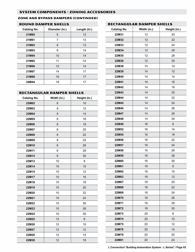
L Connection® Building Automation System - L Series® / Page 83
SYSTEM COMPONENTS - ZONING ACCESSORIES
ZONE AND BYPASS DAMPERS (CONTINUED)
ROUND DAMPER SHELLSCatalog No. Diameter (in.) Length (in.)
21M90 6 12
21M91 7 13
21M92 8 13
21M93 9 14
21M94 10 14
21M95 11 14
21M96 12 14
21M97 14 17
21M98 16 17
34M44 18 17
RECTANGULAR DAMPER SHELLSCatalog No. Width (in.) Height (in.)
22M02 8 10
22M03 8 12
22M04 8 14
22M05 8 16
22M06 8 18
22M07 8 20
22M08 8 22
22M09 8 24
22M10 8 26
22M11 8 28
22M12 8 30
22M13 10 8
22M14 10 10
22M15 10 12
22M17 10 16
22M18 10 18
22M19 10 20
22M20 10 22
22M21 10 24
22M22 10 26
22M23 10 28
22M24 10 30
22M25 12 8
22M26 12 10
22M27 12 12
22M28 12 14
22M30 12 18
RECTANGULAR DAMPER SHELLSCatalog No. Width (in.) Height (in.)
22M31 12 20
22M32 12 22
22M33 12 24
22M34 12 26
22M35 12 28
22M36 12 30
22M38 14 10
22M39 14 12
22M40 14 14
22M41 14 16
22M42 14 18
22M43 14 20
22M44 14 22
22M45 14 24
22M46 14 26
22M47 14 28
22M48 14 30
22M49 16 8
22M52 16 14
22M54 16 18
22M56 16 22
22M57 16 24
22M58 16 26
22M59 16 28
22M60 16 30
22M61 18 8
22M62 18 10
22M63 18 12
22M67 18 20
22M68 18 22
22M69 18 24
22M70 18 26
22M71 18 28
22M72 18 30
22M73 20 8
22M74 20 10
22M75 20 12
22M76 20 14
22M79 20 20
22M81 20 24

L Connection® Building Automation System - L Series® / Page 84
RECTANGULAR DAMPER SHELLSCatalog No. Width (in.) Height (in.)
22M82 20 26
22M84 20 30
22M85 22 8
22M86 22 10
22M88 22 14
22M89 22 16
22M92 24 8
22M93 24 10
22M94 24 12
22M96 24 16
22M97 24 18
22M99 26 8
23M00 26 10
23M01 26 12
23M02 26 14
23M03 26 16
23M05 26 20
23M06 28 8
23M07 28 10
23M08 28 12
23M09 28 14
23M10 28 16
23M12 28 20
23M13 30 8
23M14 30 10
23M15 30 12
23M16 30 14
23M18 30 18
23M19 30 20
30M68 32 8
30M86 32 12
30M95 32 14
31M04 32 16
RECTANGULAR DAMPER SHELLSCatalog No. Width (in.) Height (in.)
31M22 32 20
30M87 34 12
30M70 36 8
30M97 36 14
30M80 38 10
30M89 38 12
30M90 40 12
30M73 42 8
31M21 48 18
SYSTEM COMPONENTS - ZONING ACCESSORIES
ZONE AND BYPASS DAMPERS (CONTINUED)

L Connection® Building Automation System - L Series® / Page 85
SYSTEM COMPONENTS - MISCELLANEOUS ACCESSORIES
AFTER-HOURS OVERRIDE BUTTON C0SWCH20AE1- (56L16)
Momentary pushbutton used for after-hours override. Mainly used with applications that use the return air duct mount zone sensor. It can also be used with any non-communicating zone sensor for remote after-hours pushbutton applications.
Main Features of After-Hours Override Button• Single gang electrical handy box size.• Stainless steel wall mounting plate.• Simple two wire connection to any non-communicating
zone sensor. (Wires in parallel to sensor, to momentarily short sensor).
SPECIFICATIONS - AFTER-HOURS OVERRIDE BUTTONSensor Compatibility C0SNAJ01AW1- (56L80) Zone Sensor - Wall-Mount w/ Adjustment
C0SNZN07AE1- (94L60) Zone Sensor - Wall-MountC0SNDC02AE1- (56L81) Zone Sensor - Return Air Duct MountC0SNZN08AE1- (94L61) Zone Sensor - Miniature Wall-MountC0SNZN04AE1- (76M32) Zone Sensor - Flush Wall-Mount
Button Type Momentary - Normally openCover Material Stainless steelDimensions Height: 4-1/2 in.
Width: 2-3/4 in.Depth: 1/8 in.
Weight 0.2 lbs.Cable Type Two-conductor thermostat wire, 20 AWG min.
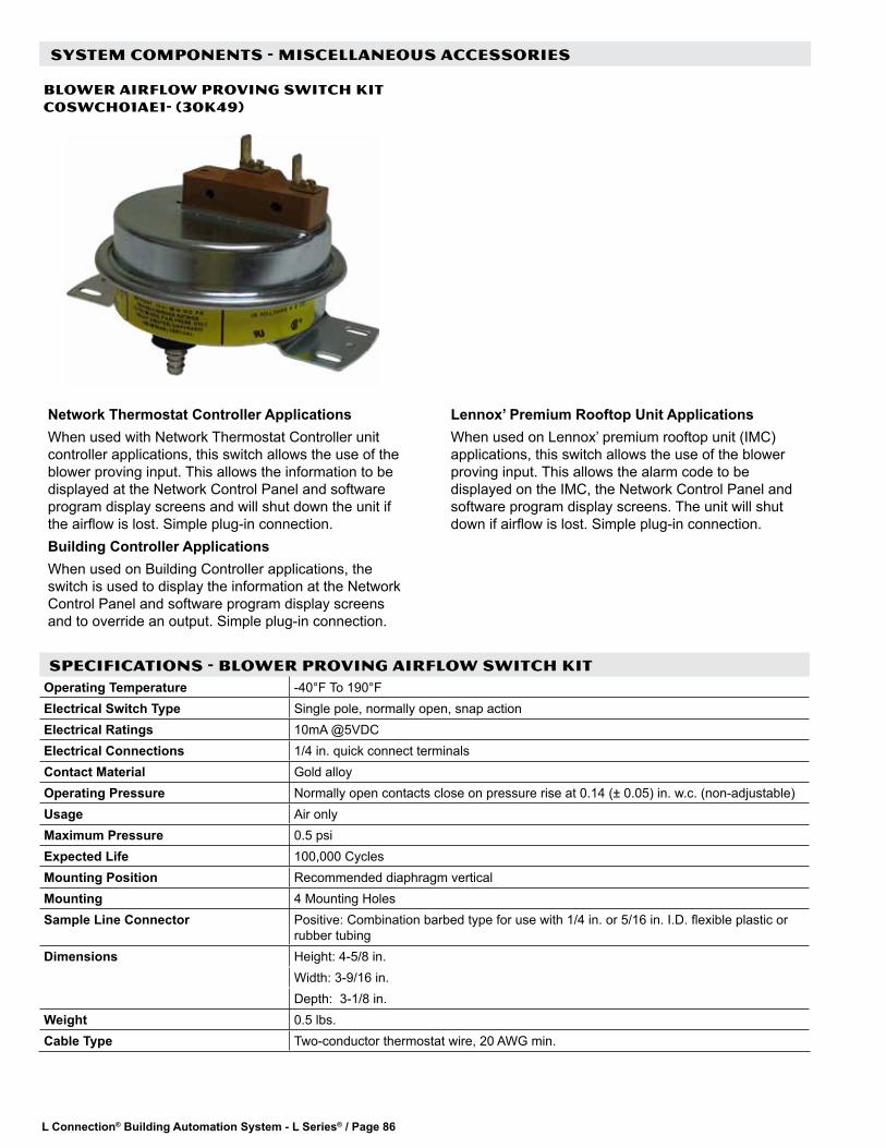
L Connection® Building Automation System - L Series® / Page 86
SYSTEM COMPONENTS - MISCELLANEOUS ACCESSORIES
BLOWER AIRFLOW PROVING SWITCH KIT C0SWCH01AE1- (30K49)
Network Thermostat Controller ApplicationsWhen used with Network Thermostat Controller unit controller applications, this switch allows the use of the blower proving input. This allows the information to be displayed at the Network Control Panel and software program display screens and will shut down the unit if the airflow is lost. Simple plug-in connection.Building Controller ApplicationsWhen used on Building Controller applications, the switch is used to display the information at the Network Control Panel and software program display screens and to override an output. Simple plug-in connection.
Lennox’ Premium Rooftop Unit ApplicationsWhen used on Lennox’ premium rooftop unit (IMC) applications, this switch allows the use of the blower proving input. This allows the alarm code to be displayed on the IMC, the Network Control Panel and software program display screens. The unit will shut down if airflow is lost. Simple plug-in connection.
SPECIFICATIONS - BLOWER PROVING AIRFLOW SWITCH KITOperating Temperature -40°F To 190°FElectrical Switch Type Single pole, normally open, snap actionElectrical Ratings 10mA @5VDC Electrical Connections 1/4 in. quick connect terminalsContact Material Gold alloyOperating Pressure Normally open contacts close on pressure rise at 0.14 (± 0.05) in. w.c. (non-adjustable) Usage Air onlyMaximum Pressure 0.5 psiExpected Life 100,000 Cycles Mounting Position Recommended diaphragm vertical Mounting 4 Mounting HolesSample Line Connector Positive: Combination barbed type for use with 1/4 in. or 5/16 in. I.D. flexible plastic or
rubber tubingDimensions Height: 4-5/8 in.
Width: 3-9/16 in. Depth: 3-1/8 in.
Weight 0.5 lbs.Cable Type Two-conductor thermostat wire, 20 AWG min.

L Connection® Building Automation System - L Series® / Page 87
SYSTEM COMPONENTS - MISCELLANEOUS ACCESSORIES
DIRTY FILTER SWITCH KIT C0SWCH00AE1- (30K48)
Network Thermostat Controller ApplicationsWhen used with Network Thermostat Controller applications, switch allows the use of the dirty filter input that will issue a dirty filter alarm. Simple plug-in connection.Building Controller ApplicationsWhen used on Building Controller applications, switch is used to display the information at the Network Control Panel and software program display screens and to override an output. Simple plug-in connection.
Lennox’ Premium Rooftop Unit ApplicationsWhen used on Lennox’ premium rooftop unit (IMC) applications, switch allows the use of the dirty filter input. This allows the alarm code to be displayed on the IMC, the Network Control Panel and software program display screens. Simple plug-in connection.
SPECIFICATIONS - DIRTY FILTER SWITCH KITOperating Temperature -40°F To 190°FElectrical Switch Type Single pole, normally open, snap actionElectrical Ratings 10mA @5VDC Electrical Connections 1/4 in. quick connect terminalsContact Material Gold alloyOperating Pressure Normally open contacts close on pressure rise at 1.0 in. w.c. (± 0.10) (non-adjustable) Usage Air onlyMaximum Pressure 0.5 psiExpected Life 100,000 cycles Mounting Position Recommended diaphragm vertical Mounting Mounting bracket furnished for installation in rooftop unitSample Line Connector Negative: Combination barbed type for use with 1/4 in. or 5/16 in. I.D. flexible plastic or
rubber tubingDimensions Height: 4-5/8 in.
Width: 3-9/16 in. Depth: 3-1/8 in.
Weight 0.5 lbs.Cable Type Two-conductor thermostat wire, 20 AWG min.

L Connection® Building Automation System - L Series® / Page 88
SYSTEM COMPONENTS - MISCELLANEOUS ACCESSORIES
DUCT PRESSURE LIMIT SWITCH C0SNSR11AE1 (79M80)
The Duct Pressure Limit Switch is used to shut down the variable frequency drive (VFD) on a variable air volume (VAV) application if the switch’s pressure setpoint is reached. A Mounting Kit C0SNSR12AE1 (79M81) is also available that includes 18 in. of vinyl tubing, tubing adapters and mounting flange with screws.
Main Features of Duct Pressure Limit Switch• Compatible with Lennox VAV units (IMC)• Adjustable setpoint
SPECIFICATIONS - DUCT PRESSURE LIMIT SWITCHOperating Temperature -30°F To 180°FElectrical Switch Type Single-pole double-throwElectrical Ratings 15 Amps @120-480VAC , derate to 10 Amps for high cycle ratesElectrical Connections Screw-type terminalsPressure Limits 45 in. w.c. continuous, 10 psig surge Setpoint Adjustment Screw-type inside conduit enclosure Deadband Approximately 0.30 in. w.c. Operating Pressure Range 1.4 to 5.5 in. w.c..Usage Air onlyMounting Position Diaphragm in vertical position Mounting Two mounting holes Sample Line Connectors Low pressure and high pressure - 1/8 in. female NPT Dimensions Height: 3-1/2 in.
Width: 3-1/2 in. Depth: 2-3/8 in.
Weight 1 lbs.Cable Type Two-conductor thermostat wire, 20 AWG min.Agency CE
ACCESSORYMounting Kit for Duct Pressure Limit Kit C0SNSR12AE1 (79M81) - Includes 18 in. of vinyl tubing, tubing adapters and
mounting flange with screws

L Connection® Building Automation System - L Series® / Page 89
SYSTEM COMPONENTS - MISCELLANEOUS ACCESSORIES
PRESSURE SWITCH C0SNSR10AE1 (79M79)
Static pressure switch used to control unit power exhaust fans on Lennox’ premium rooftop unit applications using one of the Integrated Modular Controller’s staged exhaust fan options.
SPECIFICATIONS - PRESSURE SWITCHOperating Temperature 40°F To 190°FElectrical Switch Type Single-pole single-throw, automatic resetElectrical Ratings 10mA @5VDCContact Material Gold-flashElectrical Connections Screw-type terminalsPressure Limits 13.85 in. w.c. Setpoint Range 0.05 to 12 in. w.c. Setpoint Adjustment Screw-type inside conduit enclosure Operating Pressure Range 1.4 to 5.5 in. w.c.Usage Air onlyMounting Position Diaphragm in vertical position Mounting Two mounting holesSample Line Connectors Compression fittings for 1/4 in. O.D. rigid or semi-rigid tubing,
barb fittings for 1/4 in. O.D. polyethylene tubingDimensions Height: 5-9/16 in.
Width: 6 in. Depth: 3-1/8 in.
Weight 1.3 lbs.Cable Type Two-conductor thermostat wire, 20 AWG min.Agency UL and CSA

L Connection® Building Automation System - L Series® / Page 90
SYSTEM COMPONENTS - MISCELLANEOUS ACCESSORIES
T-CLASS NTC WIRING HARNESS FOR NETWORK THERMOSTAT CONTROLLER C0MISC08BC1- (24W68)
The T-CLass NTC Wiring Harness is a complete wiring harness that plugs in to the Network Thermostat Controller and the MCC1 unit controller standard in 7.5 ton and larger T-Class rooftop units. The harness is designed to save time on installations that require adding the Network Thermostat Controller to these units.
SPECIFICATIONS - T-CLASS NTC WIRING HARNESSOverall Length 46 in. Wire Size 18 AWGConnectors (1) 24 pin edge connector J241, (1) 2 pin 5 mm pluggable J176, (1) 8 pin 5 mm
pluggable J181, (1) 9 pin 5 mm pluggable J182 and (1) spade terminal TB14-1Weight 0.38 lbs.

L Connection® Building Automation System - L Series® / Page 91
SYSTEM COMPONENTS - MISCELLANEOUS ACCESSORIES
OUTDOOR AIR WEATHER-HEAD C0SNSR22AE1- (79M21)
The Outdoor Air Weather-Head effectively reduces the fluctuation of outdoor static pressures caused by wind gusts. Eliminating this fluctuation is necessary in the control of building pressures which use outdoor static pressure as a reference.
Main Features of Outdoor Air Weather Head• Includes 50 ft. of vinyl tubing, weather-head, mounting
bracket and hardware.• Adjustable bracket for horizontal or vertical mounting.• Used with C0SNSR21AE1- (78M20) Return (Building)
Static Differential Pressure Sensor.
SPECIFICATIONS - OUTDOOR AIR WEATHER HEADTubing Length 50 ft.Tubing Size 1/8 in. IDTubing Material Vinyl

L Connection® Building Automation System - L Series® / Page 92
SYSTEM COMPONENTS - MISCELLANEOUS ACCESSORIES
PLUG-IN 24V TRANSFORMER C0MISC30AE1- (18M13)
20VA wall plug 120VAC to 24VAC transformer.
Main Features of Plug-In Transformer• 120VAC primary• 24VAC (20VA) secondary• Screw terminal 24VAC output• Black plastic enclosure
SPECIFICATIONS - PLUG-IN 24V TRANSFORMERPrimary Voltage 120VAC , 60HZSecondary Voltage 24VAC, 20VA maximum, Class 2 Secondary Terminals Two #6-32 screw terminals Overload Protection Energy limitedDimensions Height: 3 in.
Width: 2-1/2 in.Depth: 2 in.
Weight 1 lbs.Agency UL 1310 & CSA listed

L Connection® Building Automation System - L Series® / Page 93
SYSTEM COMPONENTS - MISCELLANEOUS ACCESSORIES
TRANSFORMER C0MISC32AE1- (75VA) (27W14), CoMISC33AE1- (100VA) (27W15)
75VA, 24VAC control transformer has primary taps for 120, 208, 240 and 480VAC.100VA, 24VAC control transformer has primary taps for 120, 240, 277 and 480VAC.
Main Features of Transformer• Plate or panel mounted• 9 in. leads• 1/2 in. 14 NPSM conduit connector• Circuit breaker overload protection
SPECIFICATIONS - TRANSFORMERModel No. C0MISC32AE1- (75VA) C0MISC33AE1- (100VA)Operating Temperature –20°F to 105°F –20°F to 105°FPrimary Voltage 120, 208 or 240 VAC, 60HZ 120, 240, 277 or 480 VAC, 60HZSecondary Voltage 24VAC, 75VA, Class 2 24VAC, 100VA, Class 2 Lead Wire Length 9 in. 9 in. Lead Wire Size 18AWG 18AWG Overload Protection 3.5 Amp circuit breaker , manual reset 3.5 Amp circuit breaker , manual reset Dimensions Height: 3 in. Height: 3 in.
Width: 2-1/2 in. Width: 2-1/2 in. Length: 3-15/16 in. (w/ 1/2 in. NPT hub) Length: 4-1/4 in. (w/ 1/2 in. NPT hub)
Weight 4 lbs. 4.5 lbs.Agency Meets UL standard UL 1585 for Class
2 not wet, Class 3 wet, UL listed file # E14881 guide # XOKV CSA Certified, CSA file LR95329-18 Meets NEC Class 2 requirements
Meets UL standard UL 1585 for Class 2 not wet, Class 3 wet, UL listed file # E14881 guide # XOKV CSA Certified, CSA file LR95329-18 Meets NEC Class 2 requirements
PRIMARY WIRES SECONDARY WIRESGry - 480 VAC
Org - 240 VAC
Red - 208 VAC
Wht - 120 VAC
Blk - Comm
Yel/Wht - 24 VAC
Yel - Comm
75VAPRIMARY WIRES SECONDARY WIRESGry - 480 VAC
Brn - 277 VAC
Org - 240 VAC
Wht - 120 VAC
Blk - Comm
Yel/Wht - 24 VAC
Yel - Comm
100VA
TRANSFORMER - FIELD WIRING

L Connection® Building Automation System - L Series® / Page 94
SYSTEM COMPONENTS - MISCELLANEOUS ACCESSORIES
NETWORK CONTROL PANEL SERVICE PACK 8 CoSOFT50AE1- (26W28)
Firmware upgrade for the Network Control Panel. It requires a PC with a serial port, CD-ROM disk drive and Windows® 95 to XP. Kit includes CD and cable.NOTE - This upgrade is required for use in zoning applications if an existing Network Control Panel is used.
Main Features of Network Control Panel Service Pack
• Cable plugs directly from Network Control Panel to PC serial port.
• Updates Network Control Panel to firmware version 2.01.

L Connection® Building Automation System - L Series® / Page 95
NEMA 4 HINGED ENCLOSURE C0MISC10AE1- (17M11)
NEMA 1 HINGED ENCLOSURE CoMISC14AE1 - (34M24)
NEMA 1 HINGED ENCLOSURE CoMISC13AE1 - (34M23)
The NEMA 4 Hinged Enclosure is an optional enclosure that is available for the Network Thermostat Controller, Building Controller or Zone Link.Features and Specifications• Continuous hinge, clamped cover.• Body and cover formed from 16-gauge steel.• Includes inner panel with pre-drilled holes to match the
Network Thermostat Controller mounting plate.• Three knockouts on bottom for conduit
connections.• Complies with NEMA type 3R, 4.4X, 12 and 13.• Finished with smooth ANSI/ASA 61 gray powder
coating.• Dimensions (H x W x D) - 12 x 10 x 5 in.• Weight - 15 lbs.
The NEMA 1 Hinged Enclosure is an optional enclosure that is available for the Network Thermostat Controller, Zone Link, Building Controller or the Network Modem Kit and Phone Line Auto-Router for indoor mounting.Features and Specifications• Body and cover formed from16-gauge steel.• Includes inner panel with pre-drilled holes to match the Network Thermostat Controller and Building Controller mounting plate.• Includes hook-and-loop fasteners for mounting of modem and auto-router.• Finished with smooth white paint.• Dimensions (H x W x D) - 12 x10 x 4 in.• Weight - 11.5 lbs.
SYSTEM COMPONENTS - NEMA ENCLOSURES
The NEMA 1 Hinged Enclosure is an optional enclosure that is available for the Network Control Panel and Network Modem Kit or Ethernet Converter Kit for indoor mounting.Features and Specifications• Body and cover formed from16-gauge steel.• Includes inner panel with pre-drilled holes to match the Network Control Panel mounting plate.• Includes hook-and-loop strips for mounting of modem.• Three knockouts on bottom for conduit connections.• Finished with smooth white paint.• Dimensions (H x W x D) - 14 x12 x 4 in.• Weight - 14.7 lbs.

L Connection® Building Automation System - L Series® / Page 96
SYSTEM COMPONENTS - ORDERING INFORMATION Description Model No. Order No. Page No.CONTROLLERSBuilding Controller C0CTRL80AE1L 17M12 29Network Control Panel C0CTRL10AE1L 59L21 13Network Thermostat Controller C0CTRL07AE1L 17M10 25Integrated Modular Controller - 4H/4C Module Kit C0CTRL06AE1L 86M72 23Integrated Modular Controller - I/O Module Kit C0CTRL10AE1L 86M39 21Integrated Modular Controller - VAV Module Kit C0CTRL02AE1L 86M71 19NETWORKEthernet Converter Kit C0MISC43AE1L 76M77 73Network Bus to PC Converter C0MISC47AE1- 96L78 70Network Modem Kit C0MISC46AE1- 94L62 71Network Repeater C0CTRL51AE1L 11W30 67Phone Line Auto-Router C0MISC41AE1- 34M22 72Servicew Tube Kit - - - 59W52 74Surge Protector C0MISC92AE1- 23W22 69NETWORK CABLESysBusSysBus Cable - 500 ft. Box (Yellow Jacket) C0MISC00AE1- 27M19 75SysBus Cable - 1000 ft. Box (Yellow Jacket) C0MISC04AE1- 94L63 75SysBus Cable - 2500 ft. Roll (Yellow Jacket) C0MISC01AE1- 68M25 75ZoneBusZoneBus Cable - 500 ft. Box (Purple Jacket) C0MISC05AE1- 23W99 75ZoneBus Cable - 1000 ft. Box (Purple Jacket) C0MISC06AE1- 24W00 75ZoneBus Cable - 2500 ft. Roll (Purple Jacket) C0MISC07AE1- 24W01 75SENSORSComfort Sensors - With Display and Setpoint AdjustmentTemperature, Display, Setpoint/Fan Control, After Hours Override C0SNAJ02AE1L 18W68 36Temperature, Relative Humidity, Display, Setpoint/Fan Control, After Hours Override C0SNMT10AE1L 18W66 36Temperature, CO2, Display, Setpoint/Fan Control, After Hours Override C0SNMT20AE1L 18W67 36Temperature, Relative Humidity, CO2, Display, Setpoint/Fan Control, After Hours Override C0SNMT30AE1L 18W65 36Comfort Sensors - No Display or Setpoint AdjustmentTemperature, After Hours Override C0SNZN09AE1- 18W72 36Temperature, Relative Humidity, After Hours Override C0SNMT11AE1- 18W69 36Temperature, CO2, After Hours Override C0SNMT21AE1L 18W70 36Temperature, Relative Humidity, CO2, After Hours Override C0SNMT31AE1L 18W71 36Comfort Sensors For Zoning - With Display and Setpoint AdjustmentTemperature, Display, Setpoint/Fan Control, After Hours Override, Zone Damper, Fan and Heat Control
C0SNCT01AE1L 18W58 42
Temperature, Relative Humidity, Display, Setpoint/Fan Control, After Hours Override, Zone Damper, Fan and Heat Control
C0SNCT10AE1L 18W56 42
Temperature, CO2, Display, Setpoint/Fan Control, After Hours Override, Zone Damper, Fan and Heat Control
C0SNCT20AE1L 18W57 42
Temperature, Relative Humidity, CO2, Display, Setpoint/Fan Control, After Hours Override, Zone Damper, Fan and Heat Control
C0SNCT30AE1L 18W55 42
Comfort Sensors For Zoning - No Display or Setpoint AdjustmentTemperature, After Hours Override, Zone Damper, Fan and Heat Control C0SNCT00AE1L 18W59 42Temperature, Relative Humidity, After Hours Override, Zone Damper, Fan and Heat Control
C0SNCT11AE1L 18W60 42
Temperature, CO2, After Hours Override, Zone Damper, Fan and Heat Control C0SNCT21AE1L 18W61 42Temperature, Relative Humidity, CO2, After Hours Override, Zone Damper, Fan and Heat Control C0SNCT31AE1L 18W62 42
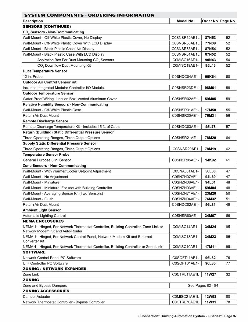
L Connection® Building Automation System - L Series® / Page 97
SYSTEM COMPONENTS - ORDERING INFORMATION Description Model No. Order No. Page No.SENSORS (CONTINUED)CO2 Sensors - Non-CommunicatingWall-Mount - Off-White Plastic Cover, No Display C0SNSR52AE1L 87N53 52Wall-Mount - Off-White Plastic Cover With LCD Display C0SNSR50AE1L 77N39 52Wall-Mount - Black Plastic Case, No Display C0SNSR53AE1L 87N54 52Wall-Mount - Black Plastic Case With LCD Display C0SNSR51AE1L 87N52 52 Aspiration Box For Duct Mounting CO2 Sensors C0MISC16AE1- 90N43 54 CO2 Downflow Duct Mounting Kit C0MISC19AE1- 85L43 52Duct Temperature Sensor12 in. Probe C0SNDC04AE1- 99K64 60Outdoor Air Control Sensor KitIncludes Integrated Modular Controller I/O Module C0SNSR23DE1- 98M61 58Outdoor Temperature SensorWater-Proof Wiring Junction Box, Vented Aluminum Cover C0SNSR02AE1- 59M05 59Relative Humidity Sensors - Non-CommunicatingWall-Mount - Off-White Plastic Case C0SNSR31AE1- 17M50 55Return Air Duct Mount C0SNSR30AE1- 76M31 56Remote Discharge SensorRemote Discharge Temperature Kit - Includes 15 ft. of Cable C0SNDC03AE1- 45L78 57Return (Building) Static Differential Pressure SensorThree Operating Ranges, Three Output Options C0SNSR21AE1- 78M20 64Supply Static Differential Pressure SensorThree Operating Ranges, Three Output Options C0SNSR20AE1 78M19 62Temperature Sensor ProbeGeneral Purpose 3 in. Sensor C0SNSR05AE1- 14K92 61Zone Sensors - Non-CommunicatingWall-Mount - With Warmer/Cooler Setpoint Adjustment C0SNAJ01AE1- 56L80 47Wall-Mount - No Adjustment C0SNZN07AE1- 94L60 47Wall-Mount - Miniature C0SNZN08AE1- 94L61 48Wall-Mount - Miniature, For use with Building Controller C0SNZN03AE1- 59M04 48Wall-Mount - Averaging Sensor Kit (Two Sensors) C0SNZN71AE1- 23M20 50Wall-Mount - Flush C0SNZN04AE1- 76M32 51Return Air Duct Mount C0SNDC02AE1- 56L81 49Ambient Light SensorAutomatic Lighting Control C0SNSR60AE1- 34M67 66NEMA ENCLOSURESNEMA 1 - Hinged, For Network Thermostat Controller, Building Controller, Zone Link or Network Modem Kit and Auto-Router
C0MISC14AE1- 34M24 95
NEMA 1 - Hinged, For Network Control Panel, Network Modem Kit and Ethernet Converter Kit
C0MISC13AE1- 34M23 95
NEMA 4 - Hinged, For Network Thermostat Controller, Building Controller or Zone Link C0MISC10AE1- 17M11 95SOFTWARENetwork Control Panel PC Software C0SOFT11AE1- 96L82 76Unit Controller PC Software C0SOFT01AE1- 96L80 77ZONING / NETWORK EXPANDERZone Link C0CTRL11AE1L 11W27 32ZONINGZone and Bypass Dampers See Pages 82 - 84ZONING ACCESSORIESDamper Actuator C0MISC21AE1L 12W98 80Network Thermostat Controller - Bypass Controller C0CTRL70AE1L 11W31 78

L Connection® Building Automation System - L Series® / Page 98
SYSTEM COMPONENTS - ORDERING INFORMATION Description Model No. Order No. Page No.MISCELLANEOUS ACCESSORIESAfter-Hours Override Button C0SWCH20AE1- 56L16 85Blower Airflow Proving Switch Kit C0SWCH01AE1- 30K49 86Dirty Filter Switch C0SWCH00AE1- 30K48 87Duct Pressure Limit Switch C0SNSR11AE1 79M80 88 Mounting Kit for Duct Pressure Limit Switch - 18 in. vinyl tubing and connectors C0SNSR12AE1 79M81 88Network Control Panel Service Pack C0SOFT50AE1- 26W28 94Outdoor Air Weather-Head C0SNSR22AE1- 79M21 91Pressure Switch C0SNSR10AE1 79M79 89T-Class Wiring Harness For Network Thermostat Controller C0MISC08BC1- 24W68 90Transformer - 120, 208, 240 and 480VAC, 60HZ Primary / 24VAC Secondary, 75VA C0MISC32AE1- 27W14 93Transformer - 120, 240, 277 and 480VAC, 60HZ Primary / 24VAC Secondary, 100VA C0MISC33AE1- 27W15 93Transformer - 24V, Plug-in C0MISC30AE1- 18M13 92


NOTE - Due to Lennox’ ongoing commitment to quality, Specifications, Ratings and Dimensions subject to change without notice and without incurring liability. Improper installation, adjustment, alteration, service or maintenance can cause property damage or personal injury. Installation and service must be performed by a qualified installer and servicing agency. ©2010 Lennox Industries, Inc.
Visit us at www.lennox.com
For the latest technical information, www.lennoxcommercial.com
Contact us at 1-800-4-LENNOX
REVISIONS
Sections Description of Change
System Components Removed discontinued dampers
System Components Removed Lennox Commercial Controls Selection Software (34M78).