L-Band Digital Aeronautical Communications System Engineering—Concepts … · ·...
161
Natalie Zelkin and Stephen Henriksen ITT Corporation Advanced Engineering & Sciences Division, Herndon, Virginia L-Band Digital Aeronautical Communications System Engineering—Concepts of Use, Systems Performance, Requirements, and Architectures NASA/CR—2010-216326 September 2010 SAA3–978–1 https://ntrs.nasa.gov/search.jsp?R=20100040566 2018-07-01T22:41:43+00:00Z
Transcript of L-Band Digital Aeronautical Communications System Engineering—Concepts … · ·...

Natalie Zelkin and Stephen HenriksenITT Corporation Advanced Engineering & Sciences Division, Herndon, Virginia
L-Band Digital Aeronautical CommunicationsSystem Engineering—Concepts of Use, SystemsPerformance, Requirements, and Architectures
NASA/CR—2010-216326
September 2010
SAA3–978–1
https://ntrs.nasa.gov/search.jsp?R=20100040566 2018-07-01T22:41:43+00:00Z

NASA STI Program . . . in Profi le
Since its founding, NASA has been dedicated to the advancement of aeronautics and space science. The NASA Scientifi c and Technical Information (STI) program plays a key part in helping NASA maintain this important role.
The NASA STI Program operates under the auspices of the Agency Chief Information Offi cer. It collects, organizes, provides for archiving, and disseminates NASA’s STI. The NASA STI program provides access to the NASA Aeronautics and Space Database and its public interface, the NASA Technical Reports Server, thus providing one of the largest collections of aeronautical and space science STI in the world. Results are published in both non-NASA channels and by NASA in the NASA STI Report Series, which includes the following report types: • TECHNICAL PUBLICATION. Reports of
completed research or a major signifi cant phase of research that present the results of NASA programs and include extensive data or theoretical analysis. Includes compilations of signifi cant scientifi c and technical data and information deemed to be of continuing reference value. NASA counterpart of peer-reviewed formal professional papers but has less stringent limitations on manuscript length and extent of graphic presentations.
• TECHNICAL MEMORANDUM. Scientifi c
and technical fi ndings that are preliminary or of specialized interest, e.g., quick release reports, working papers, and bibliographies that contain minimal annotation. Does not contain extensive analysis.
• CONTRACTOR REPORT. Scientifi c and
technical fi ndings by NASA-sponsored contractors and grantees.
• CONFERENCE PUBLICATION. Collected papers from scientifi c and technical conferences, symposia, seminars, or other meetings sponsored or cosponsored by NASA.
• SPECIAL PUBLICATION. Scientifi c,
technical, or historical information from NASA programs, projects, and missions, often concerned with subjects having substantial public interest.
• TECHNICAL TRANSLATION. English-
language translations of foreign scientifi c and technical material pertinent to NASA’s mission.
Specialized services also include creating custom thesauri, building customized databases, organizing and publishing research results.
For more information about the NASA STI program, see the following:
• Access the NASA STI program home page at http://www.sti.nasa.gov
• E-mail your question via the Internet to help@
sti.nasa.gov • Fax your question to the NASA STI Help Desk
at 443–757–5803 • Telephone the NASA STI Help Desk at 443–757–5802 • Write to:
NASA Center for AeroSpace Information (CASI) 7115 Standard Drive Hanover, MD 21076–1320
Natalie Zelkin and Stephen HenriksenITT Corporation Advanced Engineering & Sciences Division, Herndon, Virginia
L-Band Digital Aeronautical CommunicationsSystem Engineering—Concepts of Use, SystemsPerformance, Requirements, and Architectures
NASA/CR—2010-216326
September 2010
SAA3–978–1
National Aeronautics andSpace Administration
Glenn Research CenterCleveland, Ohio 44135
Prepared under Cooperative Agreement NCC05CA85C
Available from
NASA Center for Aerospace Information7115 Standard DriveHanover, MD 21076–1320
National Technical Information Service5301 Shawnee Road
Alexandria, VA 22312
Available electronically at http://gltrs.grc.nasa.gov
Trade names and trademarks are used in this report for identifi cation only. Their usage does not constitute an offi cial endorsement, either expressed or implied, by the National Aeronautics and
Space Administration.
Level of Review: This material has been technically reviewed by expert reviewer(s).
This report contains preliminary fi ndings, subject to revision as analysis proceeds.
NASA/CR—2010-216326 iii
Preface
This National Aeronautics and Space Administration (NASA) Contractor Report summarizes and documents the work performed to develop concepts of use (ConUse), System Requirements and Architecture for the proposed L-band (960 to 1164 MHz) terrestrial en route communications system.
This work was completed under a NASA project-level agreement (PLA FY09_G1M.02-02v1) for “New ATM Requirements—Future Communications” in support of a Federal Aviation Administration (FAA)/European Organisation for the Safety of Air Navigation (EUROCONTROL) Cooperative Research Agreement (Action Plan 17 (AP–17)), commonly referred to as the Future Communications Study. The work was performed with the guidance of the FAA and NASA.

NASA/CR—2010-216326 v
Executive Summary
ES.1 Introduction
This document is created under the project-level agreement (PLA) (PLA FY09_G1M.02-02v1) for “New ATM [air traffic management] Requirements—Future Communications” and addresses concepts of use (ConUse), System Requirements and Architecture for the proposed L-band (960 to 1164 MHz) terrestrial en route communications system.
The document becomes part of a hierarchy of documents capturing concepts related to the National Airspace System (NAS). NAS-level and similar level international concept of operations (ConOps) driving this ConUse and its associated requirements include the RTCA “National Airspace System Concept of Operations and Vision for the Future of Aviation” (Ref. 1), the “Joint Planning and Development Office (JPDO) Concept of Operations (ConOps) for the Next Generation Air Transportation System (NextGen)” (Ref. 2), and the “Global ATM Operational Concept Document (International Civil Aviation Organization (ICAO) 9854)” (Ref. 3). At the next lower layer, the European Organisation for the Safety of Air Navigation (EUROCONTROL) “Operating Concept of the Mobile Aviation Communication Infrastructure Supporting ATM Beyond 2015” (Ref. 4) was used with the service level ConOps, the Future Communications Study (FCS) Communications Operating Concept and Requirements (COCR) (Ref. 5) providing reference guidance for air/ground (A/G) and air/air (A/A) communications services operating concepts and requirements directly applicable to this ConUse. On a similar level to this ConUse, but with a different scope and intended for different services, are the operating concepts and requirements presented in the “Data Communications Safety and Performance Requirements (SPR)” (Ref. 6) and the Federal Aviation Administration (FAA) Final Program Requirements (FPR) for Data Communications (Ref. 7).
ES.2 ConUse
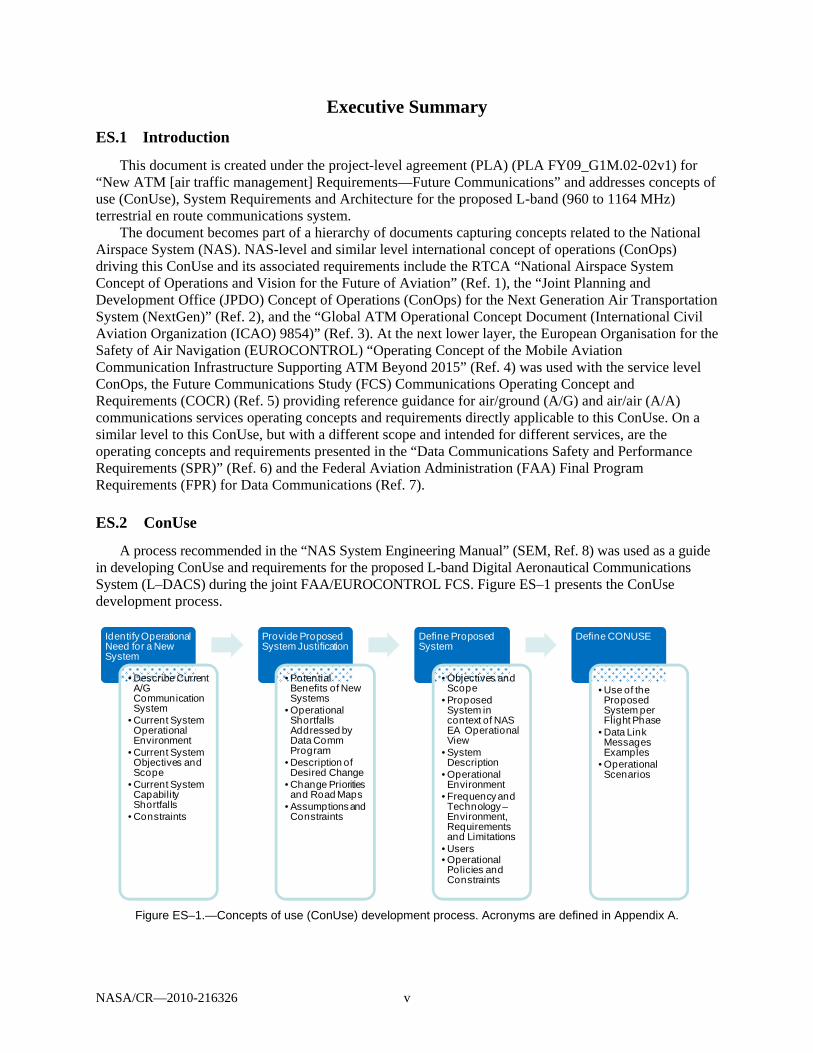
A process recommended in the “NAS System Engineering Manual” (SEM, Ref. 8) was used as a guide in developing ConUse and requirements for the proposed L-band Digital Aeronautical Communications System (L–DACS) during the joint FAA/EUROCONTROL FCS. Figure ES–1 presents the ConUse development process.
Figure ES–1.—Concepts of use (ConUse) development process. Acronyms are defined in Appendix A.
Identify Operational Need for a New System
• Describe Current A/G Communication System
• Current System Operational Environment
• Current System Objectives and Scope
• Current System Capability Shortfalls
• Constraints
Provide Proposed System Justification
• Potential Benefits of New Systems
• Operational Shortfalls Addressed by Data CommProgram
• Description of Desired Change
• Change Priorities and Road Maps
• Assumptions and Constraints
Define Proposed System
• Objectives and Scope
• Proposed System in context of NAS EA Operational View
• System Description
• Operational Environment
• Frequency and Technology –Environment, Requirements and Limitations
• Users• Operational Policies and Constraints
Define CONUSE
• Use of the Proposed System per Flight Phase
• Data Link Messages Examples
• Operational Scenarios
NASA/CR—2010-216326 vi
In summary, the following steps were taken in developing the ConUse: (1) Identify operational needs for a new system and provide proposed system justification
Operational needs for a new system are supported by describing the current system, its associated
problems, and capability shortfalls. A good description of the FAA’s current analog A/G voice communications system used for air traffic control (ATC) can be found in the Next Generation Air/Ground Communications (NEXCOM) system requirements document (Ref. 9).
The NextGen ConOps summarizes the current attributes (and associated constraints) of the voice-based A/G communications system as follows (Ref. 2):
Limited data communications for ATM and operational control Limited access to real-time weather and aeronautical data Voice communications routine for ATM Analog voice Analog weather information display systems A/G and ground/ground (G/G) communications Loss of communications due to beyond line-of-site (BLOS) aircraft position (e.g., over the ocean) Individual ground systems for each information type brought to the flight deck Point-to-point aircraft communications based on ATC sectors
There are several principal shortcomings of the current A/G voice communications system, including
lack of automation, limited or no data communications availability, aging infrastructure, technology limitations, and spectrum saturation. The resulting operational problems, if not addressed, could lead to service degradation and limit introduction of new or expanded services. These, in turn, could potentially compromise safety of operation and increase operating costs. Saturation of the very high frequency (VHF) spectrum is the problem specifically mitigated by the introduction of a new L-band system (L–DACS), while the other operational problems will likely be mitigated to a degree, dependent on the particular technology implemented with the L–DACS.
Rather than being a NAS service itself, G/G and A/G communications are enablers of NAS services. It is important to note that the FAA’s Data Communications Program (Data Comm) FPR document recognizes that “the scope of the mission shortfalls identified herein [is] broader than will be addressed solely by a data communications capability” (Ref. 7). Because of the limitations and constraints of implementing data communications using VDL Mode 2 over a congested aeronautical VHF band, the Data Comm will focus principally on implementing the most critical air traffic services. This provides opportunities for L–DACS systems to augment Data Comm by enabling communications of less critical and essential air traffic services to address the shortfalls listed. The planned Data Communications Networks Services (DCNS) A/G data communications system being developed under the Data Comm is expected to be implemented before any L–DACS is implemented and should mitigate many of the current operational problems and shortcomings, while still leaving room for additional gains in overcoming current A/G communications problems or shortcoming potentially achievable by L–DACS. Assumptions and constraints for this document are as follows:
The proposed L–DACS is assumed to provide an increase in overall A/G communications systems capacity by utilizing the new spectrum (i.e., not VHF).
The scope of this ConUse and requirements document includes A/G communications and A/A communications.
L–DACS will be designed specifically for data communication. When finalized, the technology may support voice communications, but this feature is not considered a system requirement at this time.
NASA/CR—2010-216326 vii
This report assumes that the data communications system developed as part of Data Comm will precede an L–DACS implementation and deployment.
While some critical services are proposed, the L–DACS will also target noncritical services, such as weather advisory and aeronautical information services implemented as part of an airborne System Wide Information Management (SWIM) program. It may also target one or more unmanned aircraft system (UAS) communications services.
Although the L–DACS ConUse and functional requirements developed for the document are largely technology independent, services selection and overall system requirements may change if and/ or when additional and/or different data is available from proposed L–DACS interference testing and as a result of a final selection of one of two L–DACS technologies under consideration as of the time of this report.
L–DACS is to be designed and implemented in a manner that will not disrupt other existing services operating in the L-band. Additional interference research and testing will determine if any operational constraints are to be imposed, such as limiting the number of users, time of the day, duration, and so on.
(2) Define Proposed System and ConUse L–DACS will be introduced as part of the proposed NextGen vision and will address continental en
route and terminal maneuvering area (TMA) airspace A/G communications. In addition to potentially providing an alternative link technology suitable to support the FAA’s Data
Communications Segment 3 requirements, including full four-dimensional trajectory-based operations (TBO). The L–DACS is also envisioned to support other future communications applications including mobile SWIM and UAS safety-critical data communications, UAS command and control, and monitoring of UAS onboard sense and avoid and automation capabilities.
The NextGen communications systems will enable users to play a more active role in each of the NAS service areas.
NAS management (strategic flow and resource management): SWIM capability will enable
stakeholders’ access to relevant information. Users will become key participants in the planning of traffic flow management and will utilize a comprehensive information exchange process to improve flight operations planning according to capacity and traffic conditions to minimize congestion and delays.
Flight planning and emergency alerting services: Users will have interactive flight-planning capabilities with an immediate access to real-time data. User-preferred routing will become available to properly equipped aircraft for both domestic and international flights.
Surface: Increased data exchange capabilities will provide more users at more airports with flight clearances, airports information, positions of other aircraft, taxi routes, and weather conditions (current, forecast, and hazardous). Users will have improved real-time planning with continuous update of the flight profile.
Arrival/departure and en route: A/G data exchange will enable more active flight deck participation in the decision making process. Users will utilize data, such as air traffic control clearances, current and forecast weather, notices to airmen hazardous weather warnings, updated charts, current weather, special use airspace status, and other required data.
Oceanic: A/G communication via L–DACS will not be provided in oceanic airspace.

NASA/CR—2010-216326 viii
Table ES–1provides a listing of the operational scenarios and concepts envisioned for the midterm NextGen for each of the flight phases. Though most, if not all, of these are currently envisioned for Data Comm, these are technology independent, and thus equally valid for an L–DACS implementation.
TABLE ES–1.—NEXTGEN MIDTERM OPERATIONAL CONCEPTS FOR EACH FLIGHT PHASE (REF. 10)
Phase of flight NextGen midterm communications operational concept Flight planning Access to flight planning information will be available to authorized users via a
secure network and will include a publish-and-subscribe capability so that users can receive automatic updates when conditions change along the proposed flight path.
Push back, taxi, and departure As the time for the flight approaches, the final flight path agreement will be delivered as a data message to pilots who access the agreement before beginning the flight.
Climb and cruise Data communications will increase efficiency by providing routine and strategic information to the pilot and automating certain routine tasks for both the pilot and controller.
A decreased number of voice communications also will reduce radio frequency congestion and eliminate verbal miscommunication—a great safety improvement that will reduce operational errors.
Providing changes to radio frequencies and other information, such as local barometric pressure and required weather advisories, by data communications link can also reduce errors.
When weather impacts numerous flights, clearances for data communications capable aircraft can be sent all at once, increasing controller and operator efficiency.
If potential conflicts with other aircraft or other constraints, such as weather or homeland security interventions, develop along the path, the NextGen system will identify the problem and provide recommended path trajectory or speed changes to eliminate the conflict. The controller will send the pilot the proposed change via a data communications link, if the aircraft is equipped.
When rerouting is required, the flight can be assigned precision offsets to the published route. These offsets will become a way of turning a single published route into a “multi-lane highway.” Use of offsets will increase capacity in a section of airspace. These reroutes can be tailored for each flight. Since the final agreement will be reached via data messaging, complex reroutes can be more detailed than those constrained by the limitations of voice communications and can reduce one source of error in communications.
As weather and wind conditions change above the ocean, both individual reroutes and changes to the entire route structure will be managed via a data communications link.
Descent and approach Information such as proposed arrival time, sequencing and route assignments will be exchanged with the aircraft via a data communications link to negotiate a final flight path.
Landing, taxi, and arrival Before the flight lands, both the preferred taxiway to be used for exiting the runway and the taxi path to the assigned parking will be available to the flight crew via a data communications link.

NASA/CR—2010-216326 ix
Table ES–2 illustrates the potential operational use of the proposed L-band system based on the COCR services previously identified as potential applications (Ref. 11).
TABLE ES–2.—USE OF THE PROPOSED L-BAND SYSTEM PER FLIGHT DOMAIN [Acronyms are defined in Appendix A.]
Pre-departure
APT domaina
Departure taxi APT domaina
Departure TMA
domaina
ENR ORP and AOA domains
Arrival TMA
domaina
Arrival APT domaina
Arrival taxi APT
domaina
Flight information services
D–OTISD–RVR D–SIG D–SIGMET
D–OTIS D–RVR D–SIG D–SIGMET
D–ORIS D–OTIS D–RVR D–SIG D–SIGMET
D–ORIS D–OTIS D–RVR D–SIGMET
D–OTIS D–RVR D–SIG D–SIGMET
D–OTIS D–RVR D–SIG
D–RVR D–SIG
Flight position, flight intent, and flight preferences services
PPD FLIPSYWAKE
PPD FLIPSY WAKE
PPDFLIPSY SAPb
WAKE
PPDFLIPSY SAP WAKEc
PPD FLIPSY SAP WAKE
PPD FLIPSY WAKE
PPD FLIPSY WAKE
Advisory service DYNAV Emergency information service
URCO URCO URCO URCO URCO URCO URCO
Air/air service AIRSEP Unmanned Aircraft System (UAS) aervices
Pilot/UA control links, including telecommand and telemetryPilot/UA NavAids data exchanges Relaying air traffic control (ATC) voice messages to and from UA pilots Relaying air traffic services (ATS) data messages to and from UA pilots UA-to-pilot downlinking of non-payload target track data UA-to-pilot downlinking of data from UA-borne weather radars UA-to-pilot downlinking of safety-related video data from UA to pilots UA-to-pilot downlinking of safety-related sense and avoid automated decision-making from UA to pilots
Airborne SWIM suitable services (generally weather advisory and aeronautical information services)d
Aviation Digital Data Service (ADDS)AWOS Data Acquisition Service (ADAS) Expanded Terminal and Tower Data Service General Information (GI) Message Distribution Service Information Display System (IDS) Data Service NextGen Network Enabled Weather (NNEW) Servicee Notices to Airmen (NOTAM) Distribution Service TMA Flight Data Service WARP/WINS NEXRAD Service
aWhile the L-band system is proposed to be implemented with the primary objective of supporting en route and terminal communications (i.e., ENR and TMA domains), the L-band system could be used on the ground (i.e., airport domain) as well as in the air, for example, to avoid switching the links. As such, some ATC services are included in the table for the APT domain.
bSAP is primarily used En Route and terminal areas but is available in all phases of flight. c WAKE service is not available in AOA and ORP domains dThough L–DACS could handle the technical and QoS requirements of these services, it is likely that these could more easily and
inexpensively be provided by commercial links over unprotected spectrum (Ref. 11) eIt is possible that the information provided through the NNEW service could range from the advisory for routine forecasts
through safety critical for certain hazardous weather warning messages, which might limit the extent to which this might be provided over commercial links. This requires further investigation.
A key NAS operational concepts source driving the L–DACS ConUse is the RTCA NAS ConOps.
Appendix A presents a comprehensive listing derived from the RTCA NAS ConOps of future communications concepts to enable transfer of the following NAS information types:
Surveillance Weather Flight planning Aeronautical information Resource management

NASA/CR—2010-216326 x
When discussing an impact of introducing the new L-band system, it should be emphasized that the proposed L–DACS is designed to augment current operations and is not intended to replace any of the existing services. The proposed system is expected to further increase safety and efficiency of current operations. An introduction of the proposed L-band system should require no changes to the existing L-band services operating in the same band by utilizing inlay technology and/or other interference mitigation techniques.
ES.3 Requirements
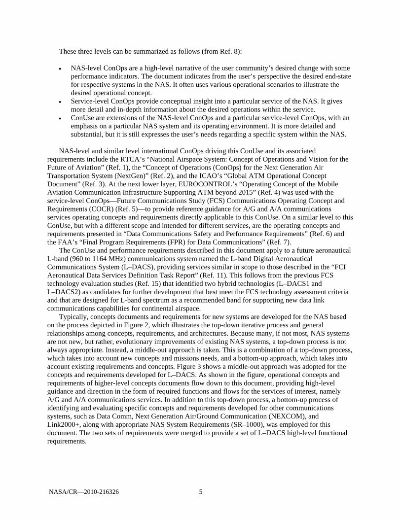
A “middle-out” approach was adopted for the concepts and requirements developed for L–DACS. Functional System Requirements were derived by merging the requirements identified in the “bottom-up” assessment with those derived as a result of the “top-down” analysis. The top-down requirements result from developing the ConUse and the associated functional requirements, including analyzing the NAS SR–1000. In parallel with that process, a bottom-up assessment of existing requirements provided in relevant documents such as the COCR, the Data Comm performance requirements, and documents associated with specific potential applications identified in Task 6 was performed.
The future communications infrastructure (FCI) aeronautical data services definition task report (Ref. 11) classifies all of the COCR ATS data services as safety critical. It further identifies services that are not planned to be implemented by the Data Comm program through Segment 3, and identifies them as possible candidates for implementation via C-band and/or L-band DACS. It must be stressed that both C-band and L-band DACS are being developed for the future communications infrastructure to accommodate safety and regularity of flight services and designed to operate over aviation protected spectrum, so any COCR ATS service could be could be implemented via one or the other of these links (as appropriate).
As described earlier, this document is focused on the non-Data Comm COCR ATS data services proposed as candidates for L–DACS as listed.
L–DACS could provide a communication link to transfer surveillance and weather information, facilitate flight and resource management, enhance collaborative decision making, and enable exchange of aeronautical information in the future NAS. Table 19 through Table 23 of Appendix A document the select RTCA NAS ConOps (Ref. 1) found applicable to the proposed L–DACS.1
Table ES–3 presents System Requirements2 associated with the identified functionality.
TABLE ES–3.—MAPPING OF SYSTEM FUNCTIONS TO SYSTEM REQUIREMENTS System Functions System Requirements
Enable ground/air (G/A) and air/ground (A/G) communication for fixed-to-mobile as well as mobile-to-mobile users.
The system shall enable G/A communication for fixed-to-mobile users. The system shall enable G/A communication for mobile-to-mobile users. The system shall enable A/G communication for fixed-to-mobile users. The system shall enable A/G communication for mobile-to-mobile users.
Enable air/air (A/A) communication The system shall enable A/A communication. Support addressed communication for delivery of information to individual and multiple users
The system shall support addressed communication for delivery of information to individual users. The system shall support addressed communication for delivery of information to multiple users.
Support broadcast communication for delivery of information to multiple users
The system shall support broadcast communication for delivery of information to multiple users.
Support delivery of real-time information in a timely manner
The system shall support delivery of real-time information in a timely manner.
1 While the RTCA document describes the NAS evolution in terms of three time periods—near (up to 2005), mid
(2005 to 2010), and far (beyond 2010). Concepts identified in the document are found applicable for the proposed L–DACS even though it is likely to be implemented beyond 2020–2025.
2 Note that all requirements presented in the document are documented as “system shall” not system “system must.”

NASA/CR—2010-216326 xi
TABLE ES–3.—MAPPING OF SYSTEM FUNCTIONS TO SYSTEM REQUIREMENTS System Functions System Requirements
Enable demand, periodic, and event communication The system shall enable demand communication. The system shall enable periodic communication. The system shall enable event communication.
Accommodate a wide range of data types (e.g., surveillance reports, weather raw data and products, flight profiles) to support common situational awareness
The system shall accommodate a wide range of data types (e.g., surveillance reports, weather raw data and products, flight profiles) to support common situational awareness
Support multiple quality-of-service (QoS) provisions The system shall support multiple QoS offerings, such as priority and preemption capabilities.
Support authentication of users and controlled access to NAS information (security)
The system shall support authentication of users (security) The system shall support controlled access to NAS information (security).
Provide support of both Federal Aviation Administration (FAA) and non-FAA ground and airborne usersa
The system shall provide support of FAA ground users. The system shall provide support of FAA airborne users. The system shall provide support of non-FAA ground users. The system shall provide support of non-FAA airborne users.
Avoid single points of failure The system shall avoid single points of failure. Provide a scalable solution The system shall provide a scalable solution. Provide standards-based solution The system shall provide standards-based solution. aTo support increasing collaboration among NAS users, the proposed system shall accommodate a wide range of NAS users by
accepting NAS data from NAS data sources, both internal and external to the FAA. Users may include aircraft, airline operation centers, service providers, FAA users, and other government agencies.
Appendix A presents hierarchical decomposition of functional requirements as diagrams and in an
outline format. The identified NAS ConOps were then traced to the desired functionality of the proposed network.
Table Es–4 below maps concepts of use identified in the ConUse activities and described in the preceding sections to specific functions necessary to enable those concepts. These functions are grouped into appropriate functional hierarchies and functional requirements are derived. The table presents the mapping of NAS ConOps to L–DACS functional requirements and proposed capabilities. This encompasses a top-down approach to the development of functional requirements. Mapping the proposed services to the desired system capabilities and functional architectures presents combined functional requirements from the top-down and bottom-up approaches.
TABLE ES–4.—TRACING L–DACS FUNCTIONALITY TO NATIONAL AIRPSACE SYSTEM (NAS) CONCEPTS OF
OPERATIONS (CONOPS) [Acronyms are defined in Appendix A.]
Desired L–DACS capabilities NAS ConOps references Functional hierarchy reference
COCR air traffic services
Enable ground/air and air/ground communication for fixed to mobile as well as mobile to mobile users.
S–1a; S–3; S–4; W–2; W–3; W–5; W–9; W–10; W–11; W–12; W–14; W–15; W–16; W–17; W–19; W–20; W–22; W–27; FM–3; FM–6; FM–9; FM–11; FM–13; FM–17; FM–21; FM–22; FM 24; FM–32; FM–41, FM–42; A–5; A–14; A–23; A–26; A–28; A–29; A–30; A–33; A–34
L.1.1.1.1 L.1.1.1.2 L.1.1.2.1 L.1.1.2.2
D–ORIS D–OTIS D–RVR DYNAV FLIPCY SAP WAKE PPD URCO
Enable air/air communication S–7; W–26
L.1.1.3.1 AIRSEP

NASA/CR—2010-216326 xii
TABLE ES–4.—TRACING L–DACS FUNCTIONALITY TO NATIONAL AIRPSACE SYSTEM (NAS) CONCEPTS OF OPERATIONS (CONOPS)
[Acronyms are defined in Appendix A.] Desired L–DACS capabilities NAS ConOps references Functional hierarchy
reference COCR air traffic
services Support addressed communication for delivery of information to individual and multiple users
S–1; W–12; FM–11; FM–13
L.1.1.1.1 L.1.1.1.2 L.1.1.2.1 L.1.1.2.2 L.1.1.3.1
D–ORIS D–OTIS D–RVR DYNAV FLIPCY SAP PPD URCO AIRSEP
Support broadcast communication for delivery of information to multiple users
S–1; S–4; W–2; W–3; W–14; W–16; W–20; W–26; FM–13; A–23
L.1.1.1.1 L.1.1.1.2 L.1.1.2.1 L.1.1.2.2 L.1.1.3.1
D–ORIS D–OTIS D–RVR WAKE URCO AIRSEP
Support delivery of real-time information in a timely manner
S–1; S–3; W–10; W–18; W–22; W–24 FM–3; FM–6; FM–14; FM–17; FM–22; FM–35; A–22; A–31; FM–4; FM–15; FM–25; FM–34; RM–3; RM–15; A–9; A–15
D–RVR DYNAV FLIPCY SAP WAKE PPD URCO AIRSEP
Enable demand, periodic, and event communication
S–1; S–8; W–14; W–19; W–20
All services
Accommodate a wide range of data types (e.g., surveillance reports, weather raw data and products, flight profiles, etc.) to support common situational awareness
S–3; W–2; W–3; A–4; A–11; A–33
All services
Support multiple quality-of-service (QoS), priority, etc.
All services
Support authentication of users and controlled access to NAS information (security)
W–1 All services
Provide support of both Federal Aviation Administration (FAA) and non-FAA ground and airborne users
S–1; FM–18; FM–21; FM–26; FM–29; A–18; A–22; A–33; A–35
Avoid single points of failure RM–14 All services Provide a scalable solution All services Provide standards-based solution All services aWhile only select NAS ConOps are presented for this L–DACS capability, most NAS ConOps could be traced to enabling
ground/air and/or air/ground communication.
ES.4 Architecture
An L–DACS physical architecture can be derived from and represents a technical solution to the functional architecture and requirements. Figure ES–2 shows a high-level notional architecture of the L–DACS system supporting A/G communication. The ground infrastructure comprises of a number of

NASA/CR—2010-216326 xiii
L–DACS ground radio stations, each providing a cell-like coverage area, and which are geographically situated to provide overlapping coverage (using different frequencies) to achieve seamless cell handovers. Each ground radio station would be connected to some G/G network through some ground network interface (number 1 in Figure ES–2).
Figure ES–2.—L–DACS architecture.
The L–DACS architecture can be further decomposed. The components would be responsible for
providing the functions identified in Appendix A and meeting L–DACS functional and performance requirements identified in Section 4 of this document.
This architecture is necessarily presented at a high level because the L–DACS ConUse so far are very broad in scope. Most of the identified high-level functional and performance requirements cannot be readily allocated to the components shown in Figure ES–2. More specifically defined ConUse and associated scenarios would make it more appropriate to further decompose the requirements and allow allocation of specific requirements to specific architecture components. This activity is recommended for Phase II.
ES.5 Conclusion
As the Data Comm is fully engaged in the development of VDL Mode 2 capabilities as of the time of this study, the FAA will follow the EUROCONTROL lead in L-band system development and plans to provide support under the pending Action Plan 30 (AP–30) FCI work plan in conducting the research and technology development for the FCI based on ICAO-endorsed findings and recommendations of the AP–17 FCS. Activities may include but will not be limited to
Supporting joint FAA/EUROCONTROL development and evaluation of the L–DACS system concepts, specifications, and prototype
Co-development of a joint interference testing program Further refinement of the upper layers of the L–DACS protocol stack
These activities will be highly dependent on cooperative planning with the European L–DACS
team(s) and their schedule.
Aircraft
ATSP Facility
End SystemInterface/Gateway
G/G Network
Ground Station
Radio System
End System
User Controls/Displays
2
3
4
5
7
Interface Description
1 GS to G/G Network
2 GS to GS Antenna
3 GS Antenna RF Interface
4 A/C Antenna RF Interface
5 A/C Radio to A/C Antenna
6 A/C Radio to A/C End System
7 A/C Radio to A/C Controls/Displays
6
1
L-DACS Physical Architecture
Ground Station
Ground Station


NASA/CR—2010-216326 xv
Contents
Preface ......................................................................................................................................................... iii Executive Summary ...................................................................................................................................... v ES.1 Introduction .......................................................................................................................................... v ES.2 ConUse ................................................................................................................................................ v ES.3 Requirements ....................................................................................................................................... x ES.4 Architecture ....................................................................................................................................... xii ES.5 Conclusion ........................................................................................................................................ xiii 1.0 Introduction .......................................................................................................................................... 1
1.1 Background ............................................................................................................................... 1 1.2 System Overview ...................................................................................................................... 2 1.3 Document Overview .................................................................................................................. 3
2.0 ConUse and Requirements Development Processes ............................................................................ 4 3.0 Concepts of Use ................................................................................................................................... 8
3.1 ConUse Development Process .................................................................................................. 8 3.2 Operational Needs ..................................................................................................................... 8
3.2.1 Current Air-to-Ground Communication System .......................................................... 8 3.2.2 Current System Operational Environment ................................................................... 9 3.2.3 Current System Users ................................................................................................. 13 3.2.4 Current System Objectives and Scope ....................................................................... 13
3.3 New Airport Surface Communications Systems Justification ................................................ 16 3.3.1 Potential Benefits of New Airport Surface Communications Systems ...................... 16 3.3.2 Operational Shortfalls Addressed by Data Comm ..................................................... 18 3.3.3 Description of Desired Changes ................................................................................. 19 3.3.4 Change Priorities and Roadmaps ............................................................................... 19 3.3.5 Assumptions and Constraints for L–DACS ............................................................... 22
3.4 Proposed L–DACS System ..................................................................................................... 22 3.4.1 Objectives and Scope ................................................................................................. 22 3.4.2 Proposed System Description ..................................................................................... 23 3.4.3 Frequency and Technology—Environment, Requirements, and Limitations ............ 27 3.4.4 User Impact ................................................................................................................ 29 3.4.5 Operational Policies and Constraints ......................................................................... 30
3.5 L–DACS Concepts of Use ...................................................................................................... 30 3.5.1 RTCA National Airspace System Concepts of Operations Guidance ........................ 30 3.5.2 Data Comm Operational Scenarios ............................................................................ 31 3.5.3 Proposed Services ...................................................................................................... 31 3.5.4 NextGen Communications Operational Concepts ...................................................... 35 3.5.5 Communications Operational Services and Concepts Based on Flight
Domain ....................................................................................................................... 36 3.5.6 L–DACS Operational Concepts Derived from the COCR ......................................... 39
4.0 L–DACS System Requirements ........................................................................................................ 41 4.1 L–DACS System Requirements Development Process .......................................................... 41 4.2 Functional Requirements for L–DACS Services—Bottom-Up Assessment ........................... 41 4.3 L–DACS Functional System Requirements—Top-Down Approach ...................................... 45
4.3.1 Prior Functional Analysis ........................................................................................... 45 4.3.2 L–DACS Concepts-of-Operations-Based Functional Analysis ................................. 46
4.4 Infrastructure Requirements—Communications ..................................................................... 51 4.5 Performance Requirements ..................................................................................................... 52 4.6 L–DACS Spectrum Requirements .......................................................................................... 55 4.7 L–DACS User Requirements .................................................................................................. 56

NASA/CR—2010-216326 xvi
4.8 Regulatory Requirements ........................................................................................................ 57 4.9 Safety and Security Requirements Applicable to L–DACS .................................................... 57
5.0 Synthesis (Physical Architecture) ...................................................................................................... 58 5.1 System Context........................................................................................................................ 58 5.2 Synthesis Process .................................................................................................................... 58 5.3 L–DACS Physical Architecture .............................................................................................. 59
6.0 Unmanned Aircraft Systems (UAS) .................................................................................................. 61 6.1 Unmanned Aircraft System Operations ................................................................................... 61 6.2 Need for Change and Impact on Existing Unmanned Aircract System Operations ................ 64 6.3 Unmanned Aircaft System ConUse and Functional Analysis ................................................. 64 6.4 Unmanned Aircraft System Applications ................................................................................ 66 6.5 Operational Scenarios .............................................................................................................. 67 6.6 Unmanned Aircraft System Requirements .............................................................................. 68
6.6.1 Spectrum Requirements ............................................................................................. 68 6.6.2 Safety and Latency Requirements .............................................................................. 68 6.6.3 Other Requirements .................................................................................................... 68
6.7 Additional Safety Considerations and Assumptions ............................................................... 69 6.8 Unmanned Aircraft System Architecture and Interfaces ......................................................... 69
7.0 Preliminary Inputs to L–DACS Design ............................................................................................. 70 7.1 Scope ....................................................................................................................................... 70 7.2 L–DACS Implementation and Transition Issues ..................................................................... 70
7.2.1 L-Band System Development Objectives (FAA Long-Term Plans) .......................... 70 7.2.2 Technology Evaluation (EUROCONTROL Long-Term Plans) ................................ 71 7.2.3 L-Band System Implementation ................................................................................. 74 7.2.4 L-Band System Transition Issues ............................................................................... 75 7.2.5 Relationship between the Proposed Systems ............................................................. 77
7.3 Summary of the Analyses ........................................................................................................ 78 7.3.1 Design Specifications Development Process ............................................................. 78 7.3.2 Spectrum Requirements and Channelization .............................................................. 79 7.3.3 Design Specifications and Prototype Development ................................................... 83
Appendix A.—Acronyms and Abbreviations ............................................................................................. 85 Appendix B.—National Airspace System Concept of Operations Applicable to the Proposed
L–DACS ............................................................................................................................................ 93 Appendix C.—Hierarchical Diagrams of Functional Requirements ........................................................ 105 Appendix D.—N2 Charts .......................................................................................................................... 119 Appendix E.—Spectrum Requirements for Unmanned Aircraft System (UAS) communications .......... 125
E.1 Single UA Throughput Needs ............................................................................................... 125 E.2 Unmanned Aircraft System (UAS) Deployment Scenario .................................................... 125 E.3 Aggregate Assessment of Unmanned Aircraft System (UAS) Spectrum Needs .................. 126 E.4 Conclusion ............................................................................................................................. 129
Appendix F.—L-Band Spectrum Applicability for Unmanned Aircraft System (UAS) Applications ..................................................................................................................................... 131
Appendix G.—References ........................................................................................................................ 133

NASA/CR—2010-216326 xvii
List of Figures
Figure ES–1.—Concepts of use (ConUse) development process. Acronyms are defined in Appendix A. ......................................................................................................................................... v
Figure ES–2.—L–DACS architecture. ....................................................................................................... xiii Figure 1.—Communications systems covered by this ConUse document (slightly altered version
of Figure 1–1 in Ref. 14). .................................................................................................................... 2 Figure 2.—National Airspace System (NAS) engineering concept document hierarchy (Ref. 8).
Acronyms are defined in Appendix A. ................................................................................................ 4 Figure 3.—Requirements management process flow (Ref. 8). Acronyms are defined in Appendix
A. ......................................................................................................................................................... 6 Figure 4.—L–DACS ConUse and system requirements development flow chart. Acronyms are
defined in Appendix A. ........................................................................................................................ 7 Figure 5.—ConUse development process. .................................................................................................... 8 Figure 6.—Current en route air-to-ground (A/G) communications system (Ref. 9). Acronyms are
defined in Appendix A. ........................................................................................................................ 9 Figure 7.—System View 2 (SV–2) command and control detailed air-to-ground communications
view for 2009 to 2010 (Ref. 17). Acronyms are defined in Appendix A. ......................................... 11 Figure 8.—Current National Airspace System air-to-ground communications operational
problems. ........................................................................................................................................... 14 Figure 9.—Operational capabilities of Data Comm (Ref. 21). Acronyms are defined in
Appendix A. ....................................................................................................................................... 19 Figure 10.—Evolution overview of aeronautical mobile communications (Ref. 20; note that this
schedule is subject to change). Acronyms are defined in Appendix A. ............................................. 20 Figure 11.—Federal Aviation Administration communications roadmap (Ref. 22). Acronyms are
defined in Appendix A. ...................................................................................................................... 21 Figure 12.—Target plan for expedited L–DACS development and deployment in Europe
(November 2007) (Ref. 20). .............................................................................................................. 21 Figure 13.—Next Generation Air Transportation System (NextGen) operational view in 2025
(Ref. 26) Acronyms are defined in Appendix A. ............................................................................... 23 Figure 14.—System view 2 (SV–2) 2025 communications description: command and control
(Ref. 27). Acronyms are defined in Appendix A. .............................................................................. 25 Figure 15.—Range of features in the NextGen system (Ref. 2). ................................................................ 26 Figure 16.—Proposed NextGen support environment. ............................................................................... 27 Figure 17.—Communication system capacity demand and user base changes. ......................................... 29 Figure 18.—Airborne System Wide Information Management (SWIM) and other Next
Generation Air Transportation System (NextGen) programs (Ref. 28). Acronyms are defined in Appendix A. ...................................................................................................................... 33
Figure 19.—Air-to-ground data link management and aircraft participation in System Wide Information Management (SWIM) (slightly modified from Ref. 30). Copyright Thales Air Systems; used with permission. Acronyms are defined in Appendix A. ........................................... 34
Figure 20.—System Wide Information Management (SWIM) execution by segments (Ref. 28). ............. 35 Figure 21.—Typical National Airspace System (NAS) flight profile and the air traffic services
(ATS) functions (Ref. 7). .................................................................................................................. 35 Figure 22.—Functional flow block diagram (from Ref. 8). ........................................................................ 46 Figure 23.—N2 diagram (from Ref. 8). ...................................................................................................... 46 Figure 24.—Example hierarchical decomposition of a National Airspace System (NAS)
architecture air traffic service (slightly modified figure from Ref. 32). ............................................ 51 Figure 25.—National Airspace System enterprise architecture airborne elements and remote
facilities (Ref. 18). Acronyms are defined in Appendix A. ............................................................... 58 Figure 26.—System requirements and architecture development synthesis loop (Ref. 8). ........................ 59

NASA/CR—2010-216326 xviii
Figure 27.—L–DACS architecture. Acronyms are defined in Appendix A. .............................................. 60 Figure 28.—L–DACS ground station components. .................................................................................... 60 Figure 29.—High-level unmanned aircraft operational functions (Ref. 36). .............................................. 64 Figure 30.—Unmanned aircraft system applications (from proposed changes to Ref. 35). ....................... 67 Figure 31.—Unmanned aircraft system (UAS) notional architecture (Ref. 36). Acronyms are
defined in Appendix A. ...................................................................................................................... 69 Figure 32.—EUROCONTROL L-band technology selection schedule (September) (Ref. 39). It
should be noted that an earlier plan for L–DACS-related activities, as documented in Ref. 40, included 2010 instead of 2011 as completion of testing and evaluation and beginning of L–DACS selection. ....................................................................................................... 72
Figure 33.—SESAR CNS systems and infrastructure roadmap (Ref. 41). Acronyms are defined in Appendix A. ....................................................................................................................................... 74
Figure 34.—Proposed L-band communications system capabilities. ......................................................... 75 Figure 35.—Relationship between the L-band system and the VDL–2 and C-band systems.
Acronyms are defined in Appendix A. .............................................................................................. 77 Figure 36.—Federal Aviation Administration (FAA) System Engineering Manual (SEM)
requirements and architecture definition process (Ref. 8). ................................................................ 78 Figure 37.—Systems operating in the 960- to 1215-MHz band (Ref. 45). Copyright Mileridge
Ltd.; used with permission. Acronyms are defined in Appendix A. .................................................. 80 Figure 38.—L-band communications system high level. ......................................................................... 105 Figure 39.—Decomposition of use L-band communications system (transmit/receive messages). ......... 105 Figure 40.—Decomposition of transceive fixed-to-mobile message. ....................................................... 106 Figure 41.—Decomposition of transceive mobile-to-fixed message. ....................................................... 107 Figure 42.—Decomposition of transceive airborne-mobile-to-airborne-mobile messages. ..................... 108 Figure 43.—Generic decomposition of transceive data message. ............................................................ 109 Figure 44.—Generic decomposition of initiate data message. ................................................................. 109 Figure 45.—Generic decomposition of process data message for sending. .............................................. 109 Figure 46.—Generic decomposition of send data message. ..................................................................... 109 Figure 47.—Generic decomposition of process received data message. .................................................. 110 Figure 48.—Generic decomposition of deliver data message. ................................................................. 110 Figure 49.—Generic decomposition of provide failure processing. ......................................................... 110 Figure 50.—Decomposition of operate L-band communications system. ................................................ 111 Figure 51.—Decomposition of monitor L-band communications system. ............................................... 111 Figure 52.—Decomposition of maintain L-band communications system. .............................................. 112 Figure 53.—Decomposition of configure L-band communications system. ............................................ 113 Figure 54.—Level 2 N2 chart, L.1 L–DACS communication system. ...................................................... 119 Figure 55.—Level 3 N2 chart, L.1.1 provide air traffic control communications over L-band
communications system. .................................................................................................................. 119 Figure 56.—Level 4 N2 chart,L.1.1.1 transceive fixed-to-mobile message. ............................................. 119 Figure 57.—Level 7 N2 chart, L.1.1.x.x.x.2 transceive data message. ..................................................... 119 Figure 58.—Level 8 N2 chart, L.1.1.x.x.x.2.1 initiate data message. ....................................................... 120 Figure 59.—Level 9 N2 chart, L.1.1.x.x.x.2.x.x. provide failure processing. ........................................... 121 Figure 60.—Level 8 N2 chart, L.1.1.x.x.x.2.2 process data message for sending. ................................... 121 Figure 61.—Level 8 N2 chart, L.1.1.x.x.x.2.3 send data message. ........................................................... 121 Figure 62.—Level 8 N2 chart, L.1.1.x.x.x.2.4 process received data message. ........................................ 121 Figure 63.—Level 8 N2 chart, L.1.1.x.x.x.2.5 deliver data message. ....................................................... 122 Figure 64.—Level 4 N2 chart, L.1.1.2 transceive mobile-to-fixed message. ............................................ 122 Figure 65.—Level 3 N2 chart, L.1.2 operate L-band communication system. ......................................... 122 Figure 66.—Level 4 N2 chart, L.1.2.1 monitor L-band communication system. ...................................... 122 Figure 67.—Level 4 N2 chart, L.1.2.2 maintain L-band communication system. .................................... 122 Figure 68.—Level 5 N2 chart, L.1.2.2.1 perform preventative maintenance. ........................................... 123

NASA/CR—2010-216326 xix
Figure 69.—Level 5 N2 chart, L.1.2.2.2 perform corrective maintenance. ............................................... 123 Figure 70.—Level 4 N2 chart, L.1.2.3 configure L-band communication system. ................................... 123 Figure 71.—Level 5 N2 chart, L.1.2.3.2 configure communication path. ................................................. 123 Figure 72.—Level 5 N2 chart, L.1.2.3.3 configure security. ..................................................................... 123 Figure 73.—Links involved for line of sight (LOS). Acronyms are defined in Appendix A. .................. 127 Figure 74.—Links involved for beyond line-of-sight (BLOS) via satellite (with onboard
processing). Acronyms are defined in Appendix A. ........................................................................ 127 Figure 75.—Links involved for beyond line-of-sight (BLOS) via satellite (without onboard
processing). Acronyms are defined in Appendix A. ........................................................................ 128


NASA/CR—2010-216326 xxi
List of Tables
TABLE ES–1.—NEXTGEN MIDTERM OPERATIONAL CONCEPTS FOR EACH FLIGHT PHASE (REF. 10) ............................................................................................................................. viii
TABLE ES–2.—USE OF THE PROPOSED L-BAND SYSTEM PER FLIGHT DOMAIN ..................... ix TABLE ES–3.—MAPPING OF SYSTEM FUNCTIONS TO SYSTEM REQUIREMENTS .................... x TABLE ES–4.—TRACING L–DACS FUNCTIONALITY TO NATIONAL AIRPSACE
SYSTEM (NAS) CONCEPTS OF OPERATIONS (ConOps) ........................................................... xi TABLE 1.—MAPPING AIR-TO-GROUND VOICE COMMUNICATIONS FUNCTIONS TO
NATIONAL AIRSPACE SERVICE (NAS) SERVICE CAPABILITIES (REF. 16). ...................... 12 TABLE 2.—CURRENT SHORTFALLS RELATED TO AIRPORT SURFACE AIR-TO-
GROUND VOICE COMMUNICATIONS ....................................................................................... 15 TABLE 3.—COMMUNICATION ALLOCATION BETWEEN VOICE AND DATA LINK
(D/L) .................................................................................................................................................. 17 TABLE 4.—L–DACS OPTIONS KEY CHARACTERISTICS (REF. 20) ............................................... 28 TABLE 5.—NEXT GENERATION AIR TRANSPORTATION SYSTEM (NextGen)
MIDTERM OPERATIONAL CONCEPTS FOR THE AIRPORT SURFACE ................................ 36 TABLE 6.—USE OF THE PROPOSED L-BAND SYSTEM IN THE AIRPORT FLIGHT
DOMAIN ........................................................................................................................................... 37 TABLE 7.—EXAMPLE L-BAND DATA LINK MESSAGES ................................................................ 38 TABLE 8.—EXAMPLE OPERATIONAL SCENARIOS ......................................................................... 39 TABLE 9.—NATIONAL AIRSPACE SYSTEM (NAS) FUNCTIONS ................................................... 41 TABLE 10.—MAPPING OF L–DACS SYSTEM FUNCTIONS TO SYSTEM
REQUIREMENTS ............................................................................................................................. 47 TABLE 11.—MAPPING L–DACS FUNCTIONALITY TO NATIONAL AIRSPACE SYSTEM
(NAS) CONCEPTS OF OPERATIONS (ConOps) ........................................................................... 48 TABLE 12.—MAPPING RELEVANT COMMUNICATIONS FUNCTIONS TO NATIONAL
AIRSPACE SYSTEM (NAS) SERVICE CAPABILITIES (REF. 16) ............................................. 50 TABLE 13.—NATIONAL AIRSPACE SYSTEM (NAS) PERFORMANCE REQUIREMENTS .......... 52 TABLE 14.—L–DACS DATA REQUIREMENTS ................................................................................... 55 TABLE 15.—NATIONAL AIRSPACE SYSTEM (NAS) SPECTRUM REQUIREMENTS
APPLICABLE TO THE PROPOSED L–DACS ............................................................................... 55 TABLE 16.—AVIATION USER REQUIREMENTS ............................................................................... 56 TABLE 17.—REGULATORY REQUIREMENTS ................................................................................... 57 TABLE 18.—UAS OPERATIONAL SCENARIOS .................................................................................. 67 TABLE 19.—THE ROLE OF SURVEILLANCE INFORMATION: RTCA NATIONAL
AIRSPACE SYSTEM (NAS) CONCEPT OF OPERATIONS (ConOps) APPLICABLE TO THE PROPOSED L–DACS .............................................................................................................. 93
TABLE 20.—THE ROLE OF SURVEILLANCE INFORMATION: RTCA NATIONAL AIRSPACE SYSTEM (NAS) CONCEPT OF OPERATIONS (ConOps) APPLICABLE TO THE PROPOSED L–DACS .............................................................................................................. 94
TABLE 21.—IDENTIFICATION OF THE ROLE OF FLIGHT MANAGEMENT INFORMATION—RTCA NATIONAL AIRPSACE SYSTEM (NAS) CONCEPT OF OPERATIONS (ConOps) .................................................................................................................. 96
TABLE 22.—IDENTIFICATION OF THE ROLE OF AERONAUTICAL INFORMATION—RTCA NATIONAL AIRPSACE (NAS) CONCEPT OF OPERATIONS (ConOps) ....................... 99
TABLE 23.—IDENTIFICATION OF THE ROLE OF RESOURCE MANAGEMENT INFORMATION—RTCA NATIONAL AIRSPACE SYSTEM (NAS) CONCEPT OF OPERATIONS (ConOps) ................................................................................................................ 102
TABLE 24.—TERRESTRIAL ESTIMATED NONPAYLOAD THROUGHPUT REQUIREMENTS OF A SINGLE UNMANNED AIRCRAFT IN BITS/S .................................. 125

NASA/CR—2010-216326 xxii
TABLE 25.—SATELLITE ESTIMATED NONPAYLOAD THROUGHPUT REQUIREMENTS OF A SINGLE UNMANNED AIRCRAFT IN BITS/S .................................................................. 125
TABLE 26.—MAXIMUM NONPAYLOAD THROUGHPUT REQUIREMENTSa OF A SINGLE UNMANNED AIRCRAFT IN BITS/S ............................................................................ 125
TABLE 27.—UNMANNED AIRCRAFTY (UA) DENSITY (60% OF UA AVAILABLE FOR OPERATION) ................................................................................................................................. 126
TABLE 28.—NUMBER OF UNMANNED AIRCRAFT PER FOOTPRINT OF THE SATELLITE .................................................................................................................................... 126
TABLE 29.—NUMBER OF UNMANNED AIRCRAFT (UA) OPERATING AT PEAK TIMESa ....... 126 TABLE 30.—AGGREGATE SPECTRUM REQUIREMENTS ............................................................. 126 TABLE 31.—METHODOLOGY 2—COMPARISON OF AGGREGATE BANDWIDTH
REQUIREMENTS ........................................................................................................................... 128
NASA/CR—2010-216326 1
1.0 Introduction
1.1 Background
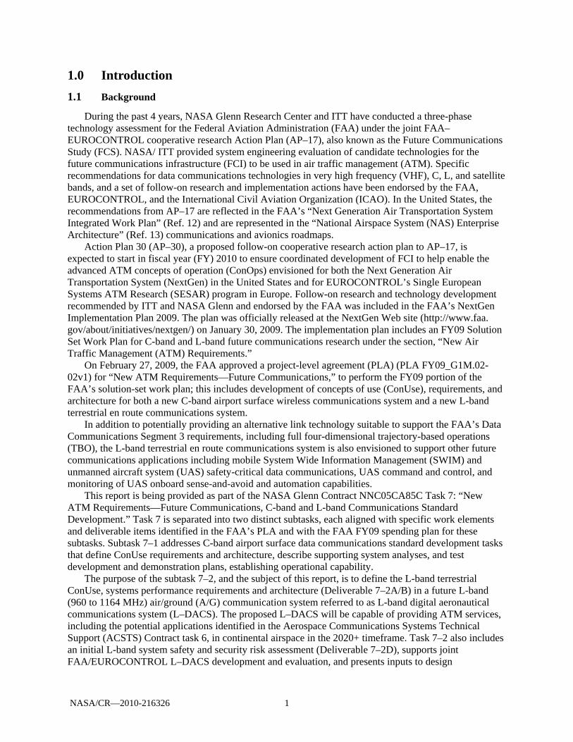
During the past 4 years, NASA Glenn Research Center and ITT have conducted a three-phase technology assessment for the Federal Aviation Administration (FAA) under the joint FAA–EUROCONTROL cooperative research Action Plan (AP–17), also known as the Future Communications Study (FCS). NASA/ ITT provided system engineering evaluation of candidate technologies for the future communications infrastructure (FCI) to be used in air traffic management (ATM). Specific recommendations for data communications technologies in very high frequency (VHF), C, L, and satellite bands, and a set of follow-on research and implementation actions have been endorsed by the FAA, EUROCONTROL, and the International Civil Aviation Organization (ICAO). In the United States, the recommendations from AP–17 are reflected in the FAA’s “Next Generation Air Transportation System Integrated Work Plan” (Ref. 12) and are represented in the “National Airspace System (NAS) Enterprise Architecture” (Ref. 13) communications and avionics roadmaps.
Action Plan 30 (AP–30), a proposed follow-on cooperative research action plan to AP–17, is expected to start in fiscal year (FY) 2010 to ensure coordinated development of FCI to help enable the advanced ATM concepts of operation (ConOps) envisioned for both the Next Generation Air Transportation System (NextGen) in the United States and for EUROCONTROL’s Single European Systems ATM Research (SESAR) program in Europe. Follow-on research and technology development recommended by ITT and NASA Glenn and endorsed by the FAA was included in the FAA’s NextGen Implementation Plan 2009. The plan was officially released at the NextGen Web site (http://www.faa. gov/about/initiatives/nextgen/) on January 30, 2009. The implementation plan includes an FY09 Solution Set Work Plan for C-band and L-band future communications research under the section, “New Air Traffic Management (ATM) Requirements.”
On February 27, 2009, the FAA approved a project-level agreement (PLA) (PLA FY09_G1M.02-02v1) for “New ATM Requirements—Future Communications,” to perform the FY09 portion of the FAA’s solution-set work plan; this includes development of concepts of use (ConUse), requirements, and architecture for both a new C-band airport surface wireless communications system and a new L-band terrestrial en route communications system.
In addition to potentially providing an alternative link technology suitable to support the FAA’s Data Communications Segment 3 requirements, including full four-dimensional trajectory-based operations (TBO), the L-band terrestrial en route communications system is also envisioned to support other future communications applications including mobile System Wide Information Management (SWIM) and unmanned aircraft system (UAS) safety-critical data communications, UAS command and control, and monitoring of UAS onboard sense-and-avoid and automation capabilities.
This report is being provided as part of the NASA Glenn Contract NNC05CA85C Task 7: “New ATM Requirements—Future Communications, C-band and L-band Communications Standard Development.” Task 7 is separated into two distinct subtasks, each aligned with specific work elements and deliverable items identified in the FAA’s PLA and with the FAA FY09 spending plan for these subtasks. Subtask 7–1 addresses C-band airport surface data communications standard development tasks that define ConUse requirements and architecture, describe supporting system analyses, and test development and demonstration plans, establishing operational capability.
The purpose of the subtask 7–2, and the subject of this report, is to define the L-band terrestrial ConUse, systems performance requirements and architecture (Deliverable 7–2A/B) in a future L-band (960 to 1164 MHz) air/ground (A/G) communication system referred to as L-band digital aeronautical communications system (L–DACS). The proposed L–DACS will be capable of providing ATM services, including the potential applications identified in the Aerospace Communications Systems Technical Support (ACSTS) Contract task 6, in continental airspace in the 2020+ timeframe. Task 7–2 also includes an initial L-band system safety and security risk assessment (Deliverable 7–2D), supports joint FAA/EUROCONTROL L–DACS development and evaluation, and presents inputs to design

NASA/CR—2010-216326 2
specifications for L-band communications systems (subtask 7–E). Subtasks associated with interference analysis and testing were postponed due to FAA’s European partners schedule change.
This report presents a combined deliverable for the subtasks 7–2 A, B, and E. The results of subtask 7–2d containing the results of the preliminary safety and security risk assessment and mitigation are reported in a separate document. Subtask 7–2C—Compatibility and Interference Analysis Study—was deleted from both Phase I and II of the subtask 7 due to lack of availability of the L–DACS prototype during the period of performance of this task.
1.2 System Overview
Systems covered by this document provide A/G communications services in support of ATM and are shown within the dashed red box shown in Figure 1. On the ground, these systems typically consist of radio ground station subsystems, including radios, antennas, cabling, power systems, environmental systems, towers, monitoring and control (M&C) functionality, and other systems to provide A/G communications services; networking subsystems to provide ground/ground (G/G) communications service connectivity to end systems and users; and usually some centralized M&C functionality to monitor and control system operations and performance. Additionally, while this document is to support definition of FAA ground-based systems; this document also covers systems providing air/air (A/A) communications services. This is also included in Figure 1.
Figure 1.—Communications systems covered by this ConUse document (slightly altered version
of Figure 1–1 in Ref. 14). It should be noted that while the figure essentially illustrates A/A and A/G communications provided
by the proposed L-band system, it includes air traffic service provider (ATSP) end-systems only. ATSP presents a subset of a broader air navigation service providers (ANSP) category that in addition to ATSP may encompass aeronautical information services providers, communication, navigation and surveillance providers, meteorological (office) service provider) and airport/aerodrome flight information service (AFIS) providers.
Aircraft System ElementOperator System Element
Air Traffic Service Provider (ATSP) System Element
Controller
Air Traffic Service Unit (ATSU)
Flight Crew
Ground – GroundCommunication
CommunicationServices
Air - GroundCommunication
Procedures(Flight Deck)
Procedures(ATSU)
Human-MachineInterface
Interface toCommunication
Services
End System(ATSU)
Aircraft System Element
End System(Aircraft)
Human-MachineInterface
Interface toCommunication
Services
Air - AirCommunication
NASA/CR—2010-216326 3
1.3 Document Overview
This document is organized as follows: Section 1.0 provides background system information and includes document scope and
organization. Section 1.0 presents the ConUse and requirements development processes. Section 3.0 is devoted to the ConUse of the proposed L–DACS. After describing the ConUse
development process, it presents the operational need for the L–DACS by describing current A/G communications systems and their associated problems and capability shortfalls. New system justification shows potential benefits of new systems and description of the desired changes. A proposed system is then described. ConUse are presented referencing the RTCA NAS ConOps guidance documents and descriptions of FAA’s Data Communications Program (Data Comm) operational scenarios, NextGen operational concepts, L–DACS operational concepts based on flight domain, as well as those derived from the communications operating concept and requirements (COCR).
Section 4.0 presents L–DACS system requirements. It describes the system requirements development process and presents the results of the middle-out approach.
Section 5.0 describes the synthesis process and introduces L–DACS physical architecture. Section 6.0 is devoted to the UAS describing their existing operations, the need for additional
communication links, and L–DACS ConUse as applicable to the UAS. Section 7.0 summarizes the preliminary inputs to L–DACS design specification. It includes an
assessment of the potential L–DACS implementation and transition issues, outlines the long-term schedule for the FAA and EUROCONTROL, and notes various factors that affect the development process. An overview of the requirements definition process and the results of previous analyses provide inputs to the design specification.
Appendix A defines acronyms and abbreviations used in this report. Appendix A summarizes RTCA NAS ConOps applicable to the proposed L–DACS. Appendix C presents hierarchical diagrams of functional requirements. Appendix D contains N2 diagrams illustrating L–DACS functional requirements. Appendix E describes spectrum requirements for UAS communications. Appendix F discusses spectrum applicability for UAS applications.
NASA/CR—2010-216326 4
2.0 ConUse and Requirements Development Processes
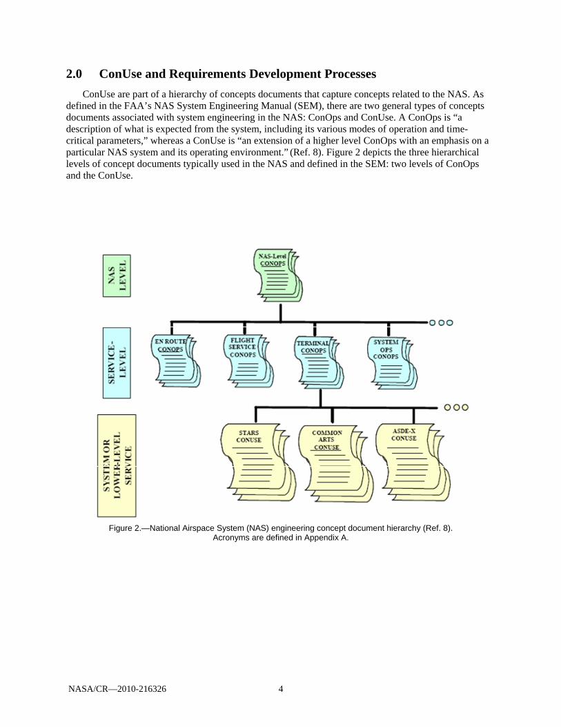
ConUse are part of a hierarchy of concepts documents that capture concepts related to the NAS. As defined in the FAA’s NAS System Engineering Manual (SEM), there are two general types of concepts documents associated with system engineering in the NAS: ConOps and ConUse. A ConOps is “a description of what is expected from the system, including its various modes of operation and time-critical parameters,” whereas a ConUse is “an extension of a higher level ConOps with an emphasis on a particular NAS system and its operating environment.” (Ref. 8). Figure 2 depicts the three hierarchical levels of concept documents typically used in the NAS and defined in the SEM: two levels of ConOps and the ConUse.
Figure 2.—National Airspace System (NAS) engineering concept document hierarchy (Ref. 8).
Acronyms are defined in Appendix A.
NASA/CR—2010-216326 5
These three levels can be summarized as follows (from Ref. 8): NAS-level ConOps are a high-level narrative of the user community’s desired change with some
performance indicators. The document indicates from the user’s perspective the desired end-state for respective systems in the NAS. It often uses various operational scenarios to illustrate the desired operational concept.
Service-level ConOps provide conceptual insight into a particular service of the NAS. It gives more detail and in-depth information about the desired operations within the service.
ConUse are extensions of the NAS-level ConOps and a particular service-level ConOps, with an emphasis on a particular NAS system and its operating environment. It is more detailed and substantial, but it is still expresses the user’s needs regarding a specific system within the NAS.
NAS-level and similar level international ConOps driving this ConUse and its associated
requirements include the RTCA’s “National Airspace System: Concept of Operations and Vision for the Future of Aviation” (Ref. 1), the “Concept of Operations (ConOps) for the Next Generation Air Transportation System (NextGen)” (Ref. 2), and the ICAO’s “Global ATM Operational Concept Document” (Ref. 3). At the next lower layer, EUROCONTROL’s “Operating Concept of the Mobile Aviation Communication Infrastructure Supporting ATM beyond 2015” (Ref. 4) was used with the service-level ConOps—Future Communications Study (FCS) Communications Operating Concept and Requirements (COCR) (Ref. 5)—to provide reference guidance for A/G and A/A communications services operating concepts and requirements directly applicable to this ConUse. On a similar level to this ConUse, but with a different scope and intended for different services, are the operating concepts and requirements presented in “Data Communications Safety and Performance Requirements” (Ref. 6) and the FAA’s “Final Program Requirements (FPR) for Data Communications” (Ref. 7).
The ConUse and performance requirements described in this document apply to a future aeronautical L-band (960 to 1164 MHz) communications system named the L-band Digital Aeronautical Communications System (L–DACS), providing services similar in scope to those described in the “FCI Aeronautical Data Services Definition Task Report” (Ref. 11). This follows from the previous FCS technology evaluation studies (Ref. 15) that identified two hybrid technologies (L–DACS1 and L–DACS2) as candidates for further development that best meet the FCS technology assessment criteria and that are designed for L-band spectrum as a recommended band for supporting new data link communications capabilities for continental airspace.
Typically, concepts documents and requirements for new systems are developed for the NAS based on the process depicted in Figure 2, which illustrates the top-down iterative process and general relationships among concepts, requirements, and architectures. Because many, if not most, NAS systems are not new, but rather, evolutionary improvements of existing NAS systems, a top-down process is not always appropriate. Instead, a middle-out approach is taken. This is a combination of a top-down process, which takes into account new concepts and missions needs, and a bottom-up approach, which takes into account existing requirements and concepts. Figure 3 shows a middle-out approach was adopted for the concepts and requirements developed for L–DACS. As shown in the figure, operational concepts and requirements of higher-level concepts documents flow down to this document, providing high-level guidance and direction in the form of required functions and flows for the services of interest, namely A/G and A/A communications services. In addition to this top-down process, a bottom-up process of identifying and evaluating specific concepts and requirements developed for other communications systems, such as Data Comm, Next Generation Air/Ground Communication (NEXCOM), and Link2000+, along with appropriate NAS System Requirements (SR–1000), was employed for this document. The two sets of requirements were merged to provide a set of L–DACS high-level functional requirements.

NASA/CR—2010-216326 6
Figure 3.—Requirements management process flow (Ref. 8). Acronyms are defined in Appendix A.
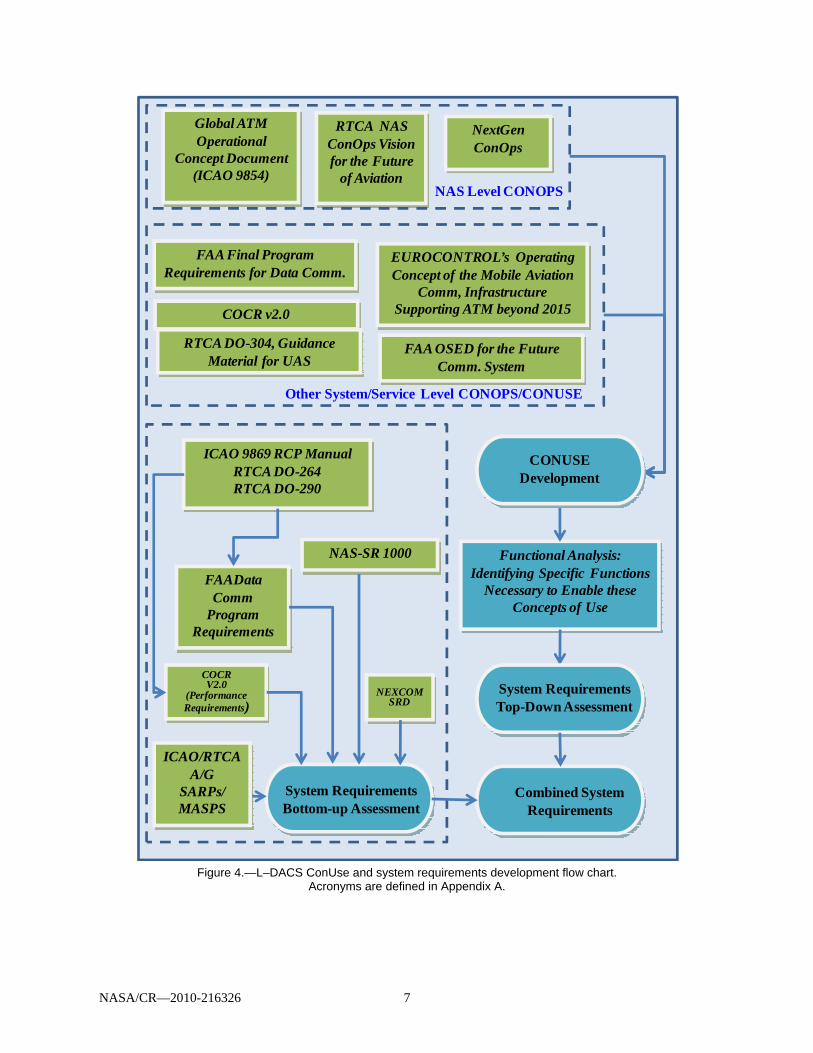
NASA/CR—2010-216326 7
Figure 4.—L–DACS ConUse and system requirements development flow chart.
Acronyms are defined in Appendix A.
FAA OSED for the Future Comm. System
NextGenConOps
EUROCONTROL’s Operating Concept of the Mobile Aviation
Comm, Infrastructure Supporting ATM beyond 2015
FAA Final Program Requirements for Data Comm.
RTCA NAS ConOps Vision for the Future
of Aviation
COCR v2.0
Global ATM Operational
Concept Document (ICAO 9854)
FAADataComm
Program Requirements
Functional Analysis: Identifying Specific Functions
Necessary to Enable these Concepts of Use
COCRV2.0
(PerformanceRequirements)
ICAO 9869 RCP ManualRTCA DO-264RTCA DO-290
Other System/Service Level CONOPS/CONUSE
RTCA DO-304, Guidance Material for UAS
NAS Level CONOPS
NAS-SR 1000
System Requirements Bottom-up Assessment
Combined System Requirements
System Requirements Top-Down Assessment
ICAO/RTCAA/G
SARPs/MASPS
NEXCOMSRD
CONUSE Development

NASA/CR—2010-216326 8
3.0 Concepts of Use
3.1 ConUse Development Process
A process recommended in the NAS system engineering manual (SEM, Ref. 8) was used as a guide in developing ConUse for the proposed L–DACS. Figure 5 summarizes the steps. The following sections describe the findings for each of the steps shown in the figure.
Figure 5.—ConUse development process.
3.2 Operational Needs
This section defines the operational needs for the L–DACS by describing current and planned A/G communications systems and their associated problems and capability shortfalls. Though not a current system at this time, the planned data communications networks services (DCNS) A/G data communications system being developed under the FAA’s Data Comm Program is discussed here because it is expected to be implemented before any L–DACS is implemented and should mitigate many of the current operational problems and shortcomings, while still leaving room for L–DACS to provide additional gains in overcoming current A/G communications problems and shortcomings.
3.2.1 Current Air-to-Ground Communication System
A good description of the FAA’s current analog A/G voice communications system used for air traffic control (ATC) can be found in the NEXCOM system requirement document (Ref. 9).
The current A/G Communications System for ATC consists of voice-based networks that use DSB–AM radios and operate in the 117.975 to 137 Megahertz (MHz) VHF band for civil aircraft and the 225 to 400 MHz UHF band for military aircraft. The radios operate with the same frequency used for controller-to-pilot (uplink) and pilot-to-controller (downlink) transmissions in a simplex “push-to-talk” mode. There is a dedicated, non-interconnected radio network for each operational environment (En Route, Terminal, airport surface, and flight service). In the event of a control facility power loss,
Identify Operational Need for a New System
• Describe Current A/G Communication System
• Current System Operational Environment
• Current System Objectives and Scope
• Current System Capability Shortfalls
• Constraints
Provide Proposed System Justification
• Potential Benefits of New Systems
• Operational Shortfalls Addressed by Data CommProgram
• Description of Desired Change
• Change Priorities and Road Maps
• Assumptions and Constraints
Define Proposed System
• Objectives and Scope
• Proposed System in context of NAS EA Operational View
• System Description
• Operational Environment
• Frequency and Technology –Environment, Requirements and Limitations
• Users• Operational Policies and Constraints
Define CONUSE
• Use of the Proposed System per Flight Phase
• Data Link Messages Examples
• Operational Scenarios
NASA/CR—2010-216326 9
engine generators provide back-up power. In the event of equipment failure, A/G communications are provided by Backup Emergency Communications (BUEC) in the Enroute, Emergency Communications System (ECS) in the large TRACONS and portable transceivers in the smaller TRACONS and Air Traffic Control Towers (ATCT).
The current A/G communications system architecture is roughly the same for all operational environments. The specific equipment used in the A/G communications string can differ among the various facilities. Different control facility types have different voice switches, with each type of switch having a unique interface.
Figure 6 shows this system for en route A/G communications. Similar architectures are in place for terminal area and airport surface area A/G communications. A very good description of the current A/G voice communications architecture and facilities is provided in Appendix A of the NEXCOM system requirements document (Ref. 9).
Figure 6.—Current en route air-to-ground (A/G) communications system (Ref. 9). Acronyms are defined in
Appendix A.
3.2.2 Current System Operational Environment
According to the SEM (Ref. 8), the operational environment of a system consists of
the conditions in which the mission or function is planned and carried out. Operational conditions are human-created conditions involving operations such as air traffic density, communication congestion, and workload. Part of the operational environment may be described by the type of operation (air traffic control, air carrier, general aviation); phase
Stnby
Stnby
Stnby
Stnby
VHF Radio DSB AM
CockpitDisplay
Management Unit
F light Data Recorder
VoiceRecorder
AIRCRAF T
VHF R adioDSB AM
Host Computer
VSCS Voice Switch
DSR (Controller’s
Console)
Microphone Speaker
Keyboard Trackball
Display Dem
arc
Dem
arc
TelcomNetwork
Vo ice Control Combined Vo ice & Control
RCAG VHF R xDSB AM
Stnby
VHF TxDSB AM
StnbyUHF RxDSB AM
Stnby
UH F TxDSB AM
Stnby
BU EC VHF Rx DSB AM VHF Tx DSB AM
UHF RxDSB AM
U HF TxDSB AM
RCE
RC E
RCE
RCE
AR TCC
Modem
VHF RadioDSB AM
CockpitAudi o
CockpitRadio Control
VHF Rx DSB AM
Local R ad ios
VHF Tx DSB AM
Analog VoiceDSB AM
U HF Rx DSB AM
UHF DSB AM
Tx
RCE
RCE
Stnby
Stnby
Stnby
Stnby
VHF Radio DSB AM
CockpitDisplay
Management Unit
F light Data Recorder
VoiceRecorder
AIRCRAF T
VHF R adioDSB AM
Host Computer
VSCS Voice Switch
DSR (Controller’s
Console)
Microphone Speaker
Keyboard Trackball
Display Dem
arc
Dem
arc
TelcomNetwork
Vo ice Control Combined Vo ice & Control
RCAG VHF R xDSB AM
Stnby
VHF TxDSB AM
StnbyUHF RxDSB AM
Stnby
UH F TxDSB AM
Stnby
BU EC VHF Rx DSB AM VHF Tx DSB AM
UHF RxDSB AM
U HF TxDSB AM
RCE
RC E
RCE
RCE
AR TCC
Modem
VHF RadioDSB AM
CockpitAudi o
CockpitRadio Control
VHF Rx DSB AM
Local R ad ios
VHF Tx DSB AM
Analog VoiceDSB AM
U HF Rx DSB AM
UHF DSB AM
Tx
RCE
RCE

NASA/CR—2010-216326 10
[of flight] (ground taxiing, takeoff, approach, en route, transoceanic, landing); or rules governing the operation (Instrument Flight Rules versus Visual Flight Rules).
Rather than being a NAS service itself, G/G and A/G communications are enablers of NAS services and provides the following functionality (Ref. 16):
Communications enables the NAS to exchange information with users, specialists, ATC facilities, and other Government agencies. Communications enables air traffic control operations within the NAS by employing appropriate technologies to exchange voice and data. This information is transported over land lines and wireless connectivity utilizing government and commercial assets. Communications defines how data is moved across the NAS to accomplish flight planning, control functions and navigation services for ground and space based systems. This enabler provides end-to-end service to pilots to include disseminating and coordinating the flight plan and defines how controllers provide service throughout the flight while coordinating with other facilities and government agencies. The communications enabler supports collaboration between users and specialists for traffic synchronization and flow services. Communications support the exchange of navigation and surveillance information across the NAS. Information includes electronic signals emanating from ILS, VOR and space based systems and aircraft transmitted beacon code data.
Reference 17, which gives an as-is system view 2 (SV–2) of the NAS, describes how NAS interfaces, as identified in the NAS system view 1 (SV–1) (Ref. 18), are supported by physical media.
Pertinent information about communications systems, communications links, and communications networks is presented as a pictorial view of system interactions and telecommunications service characteristics along with implementation technologies. Six as-is SV–2 views were developed depicting an overall telecommunications infrastructure and providing separate views for five information flow areas:
Surveillance Weather Command and control Flight data Aeronautical information An overview chart depicting an SV–2 telecommunications view and associated data for the command
and control functional flow area is presented in Figure 7. Specifically, A/G communications is mainly used for communications between air traffic controllers
or specialists on the ground and manned aircraft pilots to enable the following required NAS functions (Ref. 16):3
Manage flight plans (plan flights) Monitor aircraft status (monitor flights) Control aircraft (control traffic) Manage weather information (support flight operations) Maintain NAS infrastructure (monitor NAS operations) Plan traffic flow (plan NAS usage) Assess traffic flow performance (plan NAS usage)
3In the listing the subfunction is shown, followed by the parent function in parentheses.
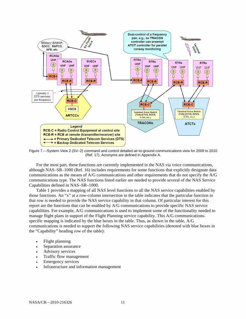
NASA/CR—2010-216326 11
Figure 7.—System View 2 (SV–2) command and control detailed air-to-ground communications view for 2009 to 2010
(Ref. 17). Acronyms are defined in Appendix A. For the most part, these functions are currently implemented in the NAS via voice communications,
although NAS–SR–1000 (Ref. 16) includes requirements for some functions that explicitly designate data communications as the means of A/G communications and other requirements that do not specify the A/G communications type. The NAS functions listed earlier are needed to provide several of the NAS Service Capabilities defined in NAS–SR–1000.
Table 1 provides a mapping of all NAS level functions to all the NAS service capabilities enabled by those functions. An “x” at a row-column intersection in the table indicates that the particular function in that row is needed to provide the NAS service capability in that column. Of particular interest for this report are the functions that can be enabled by A/G communications to provide specific NAS service capabilities. For example, A/G communications is used to implement some of the functionality needed to manage flight plans in support of the Flight Planning service capability. This A/G communications-specific mapping is indicated by the blue boxes in the table. Thus, as shown in the table, A/G communications is needed to support the following NAS service capabilities (denoted with blue boxes in the “Capability” heading row of the table):
Flight planning Separation assurance Advisory services Traffic flow management Emergency services Infrastructure and information management
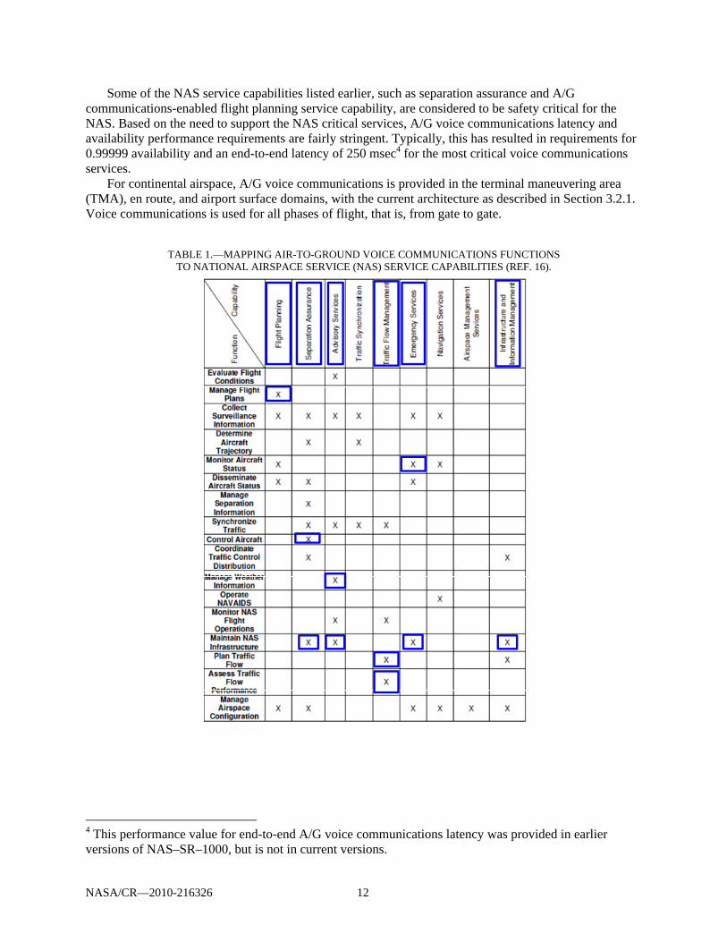
NASA/CR—2010-216326 12
Some of the NAS service capabilities listed earlier, such as separation assurance and A/G communications-enabled flight planning service capability, are considered to be safety critical for the NAS. Based on the need to support the NAS critical services, A/G voice communications latency and availability performance requirements are fairly stringent. Typically, this has resulted in requirements for 0.99999 availability and an end-to-end latency of 250 msec4 for the most critical voice communications services.
For continental airspace, A/G voice communications is provided in the terminal maneuvering area (TMA), en route, and airport surface domains, with the current architecture as described in Section 3.2.1. Voice communications is used for all phases of flight, that is, from gate to gate.
TABLE 1.—MAPPING AIR-TO-GROUND VOICE COMMUNICATIONS FUNCTIONS TO NATIONAL AIRSPACE SERVICE (NAS) SERVICE CAPABILITIES (REF. 16).
4 This performance value for end-to-end A/G voice communications latency was provided in earlier versions of NAS–SR–1000, but is not in current versions.
NASA/CR—2010-216326 13
3.2.3 Current System Users
The users of the current VHF A/G communications system include the following (Ref. 19): (1) Scheduled air transport carriers (including international, trunk, regional, commuter, and air
freight carriers) (2) Nonscheduled air carriers (3) General aviation (GA) (including operators of turbine-powered and reciprocating-engine
aircraft) (4) Operators of unpowered aircraft (including gliders and lighter-than-air aircraft) (5) Operators of various military aircraft (6) Operators of certain ground and maritime vehicles (e.g., airport service vehicles, those vehicles
coordinating in a search-and-rescue mission) (7) ATS providers (8) Aeronautical operational control (AOC) service providers
3.2.4 Current System Objectives and Scope
The objectives of the current A/G communications system are consistent with the provisions of the NAS service capabilities and performance requirements listed in Section 3.2.2. Currently, they are characterized by “high availability, low end-to-end latencies, the ability to convey human feelings, flexibility of dialogue, provision of a party-line, and use for non-routine, time critical, or emergency situations” (Ref. 5).
Some of these characteristics actually offer an advantage to voice communications as compared to data communications; however, there are several disadvantages of voice communications that motivate the need for data communications for many applications.
The NextGen ConOps has summarized the current attributes (and associated constraints) of the voice based A/G communications system as follows (Ref. 2):
Limited data communications for ATM and operational control Limited access to real-time weather and aeronautical data Voice communications routine for ATM Analog voice Analog weather information display systems A/G and G/G communications Loss of communications due to beyond line-of-site (BLOS) aircraft position (e.g., over the ocean) Individual ground systems for each information type brought to the flight deck Point-to-point aircraft communications based on ATC sectors Currently continental A/G voice communications systems operate over the VHF and UHF
aeronautical mobile (route) service (AM(R)S) frequency bands; the scope of operation is constrained to be radio line of sight, which dictates the need for networks of ground radio stations to provide radiofrequency (RF) coverage for the entire airspace volume for which the NAS service is to be provided. This is usually not a problem for A/G communications with manned aircraft. However, this offers a constraint to the routine operation in the NAS of UAS, which, when operating under a Certificate of Authorization providing it a special waiver for conducting a flight in the NAS, often operate in beyond line of sight conditions using non protected frequency bands (i.e., not AM(R)S or aeronautical mobile satellite (route) service (AMS(R)S frequency bands). Other operational constraints for UAS are described in Section 6.0.
Figure 8 summarizes several principal shortcomings of the current A/G voice communications system, including lack of automation, limited or no data communications availability, aging infrastructure, technology limitations, and spectrum saturation. The resulting operational problems, if not
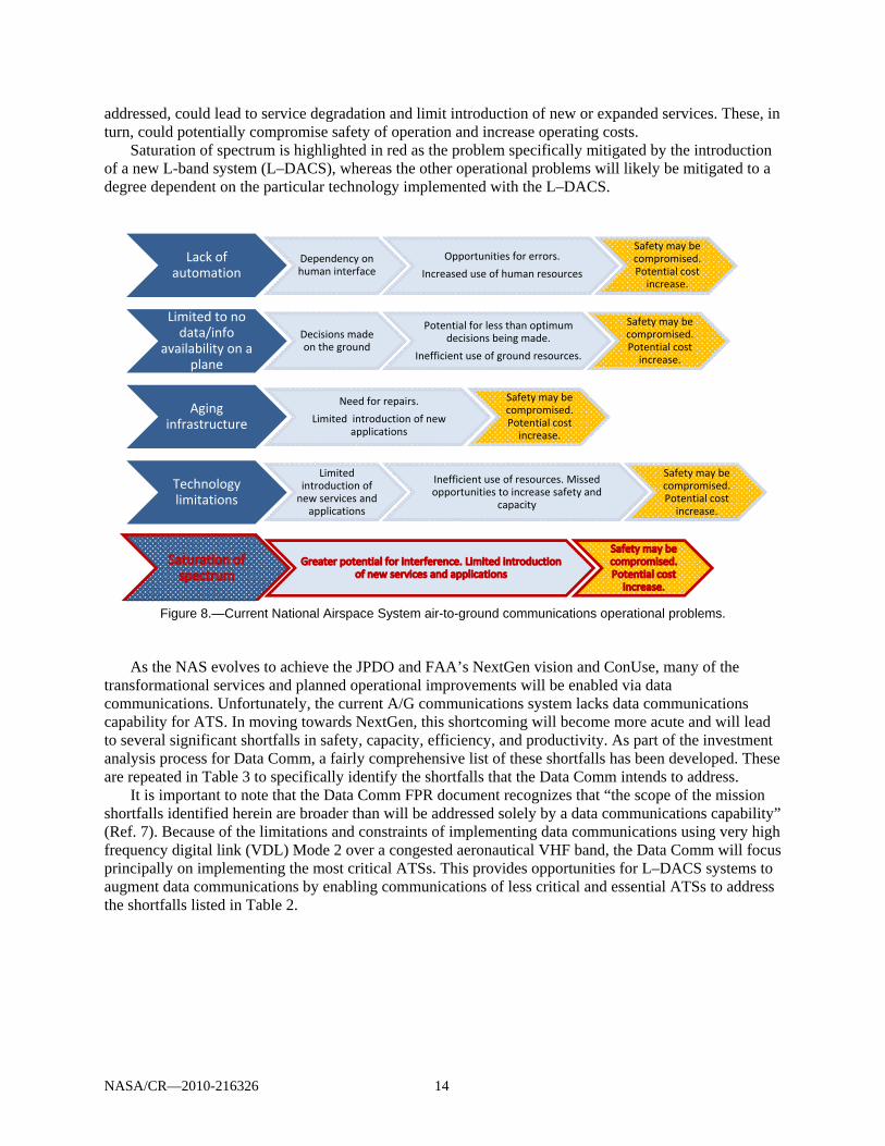
NASA/CR—2010-216326 14
addressed, could lead to service degradation and limit introduction of new or expanded services. These, in turn, could potentially compromise safety of operation and increase operating costs.
Saturation of spectrum is highlighted in red as the problem specifically mitigated by the introduction of a new L-band system (L–DACS), whereas the other operational problems will likely be mitigated to a degree dependent on the particular technology implemented with the L–DACS.
Figure 8.—Current National Airspace System air-to-ground communications operational problems.
As the NAS evolves to achieve the JPDO and FAA’s NextGen vision and ConUse, many of the
transformational services and planned operational improvements will be enabled via data communications. Unfortunately, the current A/G communications system lacks data communications capability for ATS. In moving towards NextGen, this shortcoming will become more acute and will lead to several significant shortfalls in safety, capacity, efficiency, and productivity. As part of the investment analysis process for Data Comm, a fairly comprehensive list of these shortfalls has been developed. These are repeated in Table 3 to specifically identify the shortfalls that the Data Comm intends to address.
It is important to note that the Data Comm FPR document recognizes that “the scope of the mission shortfalls identified herein are broader than will be addressed solely by a data communications capability” (Ref. 7). Because of the limitations and constraints of implementing data communications using very high frequency digital link (VDL) Mode 2 over a congested aeronautical VHF band, the Data Comm will focus principally on implementing the most critical ATSs. This provides opportunities for L–DACS systems to augment data communications by enabling communications of less critical and essential ATSs to address the shortfalls listed in Table 2.
Lack of automation
Dependency on human interface
Opportunities for errors.
Increased use of human resources
Safety may be compromised. Potential cost increase.
Limited to no data/info
availability on a plane
Decisions made on the ground
Potential for less than optimum decisions being made.
Inefficient use of ground resources.
Safety may be compromised. Potential cost increase.
Aging infrastructure
Need for repairs.
Limited introduction of new applications
Safety may be compromised. Potential cost increase.
Technology limitations
Limited introduction of new services and
applications
Inefficient use of resources. Missed opportunities to increase safety and
capacity
Safety may be compromised. Potential cost increase.
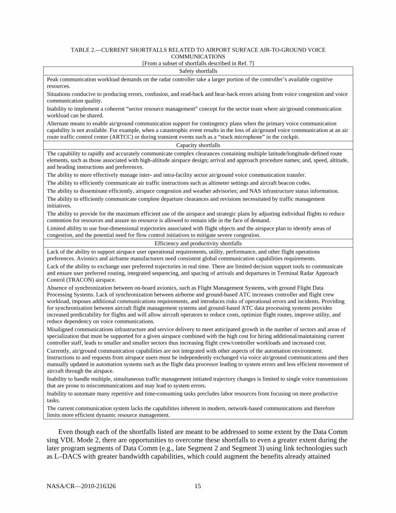
NASA/CR—2010-216326 15
TABLE 2.—CURRENT SHORTFALLS RELATED TO AIRPORT SURFACE AIR-TO-GROUND VOICE COMMUNICATIONS
[From a subset of shortfalls described in Ref. 7] Safety shortfalls
Peak communication workload demands on the radar controller take a larger portion of the controller’s available cognitive resources. Situations conducive to producing errors, confusion, and read-back and hear-back errors arising from voice congestion and voice communication quality. Inability to implement a coherent “sector resource management” concept for the sector team where air/ground communication workload can be shared. Alternate means to enable air/ground communication support for contingency plans when the primary voice communication capability is not available. For example, when a catastrophic event results in the loss of air/ground voice communication at an air route traffic control center (ARTCC) or during transient events such as a “stuck microphone” in the cockpit.
Capacity shortfalls The capability to rapidly and accurately communicate complex clearances containing multiple latitude/longitude-defined route elements, such as those associated with high-altitude airspace design; arrival and approach procedure names; and, speed, altitude, and heading instructions and preferences. The ability to more effectively manage inter- and intra-facility sector air/ground voice communication transfer. The ability to efficiently communicate air traffic instructions such as altimeter settings and aircraft beacon codes. The ability to disseminate efficiently, airspace congestion and weather advisories; and NAS infrastructure status information. The ability to efficiently communicate complete departure clearances and revisions necessitated by traffic management initiatives. The ability to provide for the maximum efficient use of the airspace and strategic plans by adjusting individual flights to reduce contention for resources and assure no resource is allowed to remain idle in the face of demand. Limited ability to use four-dimensional trajectories associated with flight objects and the airspace plan to identify areas of congestion, and the potential need for flow control initiatives to mitigate severe congestion.
Efficiency and productivity shortfalls Lack of the ability to support airspace user operational requirements, utility, performance, and other flight operations preferences. Avionics and airframe manufacturers need consistent global communication capabilities requirements. Lack of the ability to exchange user preferred trajectories in real time. There are limited decision support tools to communicate and ensure user preferred routing, integrated sequencing, and spacing of arrivals and departures in Terminal Radar Approach Control (TRACON) airspace. Absence of synchronization between on-board avionics, such as Flight Management Systems, with ground Flight Data Processing Systems. Lack of synchronization between airborne and ground-based ATC increases controller and flight crew workload, imposes additional communications requirements, and introduces risks of operational errors and incidents. Providing for synchronization between aircraft flight management systems and ground-based ATC data processing systems provides increased predictability for flights and will allow aircraft operators to reduce costs, optimize flight routes, improve utility, and reduce dependency on voice communications. Misaligned communications infrastructure and service delivery to meet anticipated growth in the number of sectors and areas of specialization that must be supported for a given airspace combined with the high cost for hiring additional/maintaining current controller staff, leads to smaller and smaller sectors thus increasing flight crew/controller workloads and increased cost. Currently, air/ground communication capabilities are not integrated with other aspects of the automation environment. Instructions to and requests from airspace users must be independently exchanged via voice air/ground communications and then manually updated in automation systems such as the flight data processor leading to system errors and less efficient movement of aircraft through the airspace. Inability to handle multiple, simultaneous traffic management initiated trajectory changes is limited to single voice transmissions that are prone to miscommunications and may lead to system errors. Inability to automate many repetitive and time-consuming tasks precludes labor resources from focusing on more productive tasks. The current communication system lacks the capabilities inherent in modern, network-based communications and therefore limits more efficient dynamic resource management.
Even though each of the shortfalls listed are meant to be addressed to some extent by the Data Comm sing VDL Mode 2, there are opportunities to overcome these shortfalls to even a greater extent during the later program segments of Data Comm (e.g., late Segment 2 and Segment 3) using link technologies such as L–DACS with greater bandwidth capabilities, which could augment the benefits already attained
NASA/CR—2010-216326 16
through the earlier VDL Mode 2 Data Comm program segment implementations (i.e., Segments 1 and 2) by providing a broader scope of services.
In addition to the shortfalls described in Table 3, there are significant operational and technical shortfalls in the ability of the current A/G communications system to meet the needs of UAS operating in the NAS. Further discussion of shortfalls related to UAS operations in the NAS is provided in Section 6.
3.3 New Airport Surface Communications Systems Justification
3.3.1 Potential Benefits of New Airport Surface Communications Systems
The NextGen ConOps states that “[t]ransformation of the ATM system in NextGen is necessary because of the inherent limitations of today’s system, including limits driven by human cognitive processes and verbal communications” (Ref. 2). Likewise, the joint EUROCONTROL/FAA FCS conducted for AP–17 concluded that “in the longer term, a paradigm shift will occur in the operating concept and the prime mode of communication exchanges will be based in data exchanges rather than voice communications as it is today” (Ref. 20).
The following excerpts (Ref. 2) from JDPO’s NextGen ConOps comprehensively describe the NextGen A/G network services. They are repeated here because they effectively communicate the full envisioned scope, benefits, and advantages of these services and the importance of data communications in enabling them:
With the transformed role of the flight crew and flight deck in NextGen, data communications are critical to ensuring that data is available for flight deck automation (i.e., avionics to support flight crew decision making). … Data communications are also needed to provide real-time data to the ANSP on the operational aspects of flights. In certain defined airspace, data communications are the primary means of communicating clearances, routine communications, and 4DT agreements between the ANSP and flight deck. … Voice communications are used to supplement data communications for tactical situations and for emergencies to augment procedural responses or risk mitigations. Voice communications are used to communicate with lesser-equipped aircraft in appropriate airspace. …
One of the key transformations is that air-ground voice communications are no longer limited by the assigned frequency-to-airspace sector mapping. This allows greater flexibility for developing and using airspace/traffic assignments in all airspace. Communications paths, including both voice and data, are controlled by an intelligent network. Communications between the ANSP and the flight deck are established when the flight is activated and are maintained continuously and seamlessly. This capability is linked to the flight data management function so that the system automatically manages who has authority to interact with the flight deck based on the type of agreement being negotiated or information being exchanged. Labor-intensive transfers of control and communication are automated. Data and voice communications are automatically transferred in the flight deck as the aircraft moves between ANSPs.
Data communications are central to TBO [(trajectory based operations)], including the use of 4DTs (pushback and taxi inclusive) for planning and execution on the surface, automated trajectory analysis and separation assurance, and aircraft separation assurance applications that require flight crew situational awareness of the 4DTs and short-term intent of surrounding aircraft.
In addition, as indicated above, there is increased sharing of improved common data between the flight deck, operator, and ANSP. In classic airspace where data communications will be available but not required, information exchange can take place

NASA/CR—2010-216326 17
with data communications for participating aircraft to provide an operational advantage. Common data includes ATC clearances, current and forecast weather, hazardous weather warnings, notices to airmen (NOTAMs), updated charts, current charting, special aircraft data, and other required data. Data communications also include weather observations made by the aircraft that are automatically provided to ANSPs, weather service providers, and flight operators for inclusion in weather analysis and forecasts. Each of these data communications functions are managed by required communications performance (RCP) standards.
The trend toward 2015 and beyond features a decreasing use of voice, with data becoming the primary communication link. This is shown in Table 3, which illustrates a projected allocation between voice and data communications during this period. As suggested by the table, for the en route domain, data link would become the primary means for most of the exchanges, with voice communication used for emergency messages and tactical clearances. In the TMA domain and on the airport surface, voice would remain the primary mode of communications for low delay and high availability pilot-ATC exchanges, with a data link used as a primary service for other messages and data-intensive services such as graphical weather. In all domains, voice communication would remain a backup for any data service.
TABLE 3.—COMMUNICATION ALLOCATION BETWEEN VOICE AND DATA LINK (D/L)
[Information from Ref. 4.] Pilot-controller dialog Pilot-
pilot dialog
Flight information exchange
ATM exchange
Information broadcast
Air-air surveillanceEmergency
messages Tactical
clearances Strategic
clearances Information messages
En route Voice D/L
Voice D/La
Voice D/L
Voice D/L
Voiceb D/L
Voice D/L
Voice D/L
Voice D/L D/L
TMAs Voice D/L
Voice D/L
Voice D/L
Voice D/L
Voice b D/L
Voice D/L
Voice D/L
Voice D/L D/L
Airport surface
Voice D/L
Voice Some D/L
Voice &D/L
Voice D/L
Voice D/L
Voice* D/L
Voice D/L
Voice D/L
Voice D/L D/L
Legend: Red – Primary Blue – Backup
aIn 2015, en route operational concept is purely strategic. Then, tactical data exchanges are to be used as backup either to voice or to strategic data clearance service. bNo specific requirements identified except current Traffic Information Broadcast by Aircraft (TBA) procedure.
Although a gradual introduction of data communications to the existing VHF systems should accommodate capacity requirements in the near term to midterm, additional spectrum is required to provide enough capacity to satisfy a growing demand for data communications in the far term. An L–DACS built to augment VHF voice and data communications systems already in place, including those implemented as part of the Data Comm, would increase overall communications system capacity, thus relieving congestion and allowing for introduction of additional services. Because of spectrum constraints in the aeronautical L-band, L–DACS should be built as a broadband system, potentially accommodating a wide array of applications and services that would otherwise be difficult, inefficient, or even impossible to implement.
The congestion in a heavily utilized VHF band is more prevalent in Europe, where the 8.33-kHz channelization has already been introduced. Thus, an L–DACS rollout is expected in Europe prior to the United States. In the United States, frequency management options, such as the use of 8.33-kHz channel spacing, may be considered prior to the introduction of an L-band system.
NASA/CR—2010-216326 18
3.3.2 Operational Shortfalls Addressed by Data Comm
The FAA intends for Data Comm to significantly mitigate the safety, capacity, efficiency, and productivity shortfalls described in Table 2. It is anticipated that Data Comm will support the following improvements in airspace use and capacity (Ref. 7):
Improved airspace use and capacity A more efficient A/G information and clearances exchange mechanism An additional means of communication between flight crews and controllers Reduced congestion on the voice channels Reduced operational errors and flight crew deviations resulting from misunderstood clearances
and read-back errors Trajectory-based operations Reduced controller and flight crew workload.
Data Comm is planned to be implemented in three segments (Ref. 7, see Figure 9): The first segment will facilitate data communications deployment and introduce initial four
dimensional (4–D); latitude, longitude, altitude, and time) routes. The second segment will introduce conformance management and initial 4–D agreements. The third segment will expand 4–D agreements and provide an operational environment that
allows the transfer of some separation assurance tasks from the ground to the air. An L–DACS implementation in the United States might follow or overlap Segment 2 (VDL Mode 2
implementation) and enable additional services and operational capabilities not covered by VDL Mode 2 for Data Comm.5 Figure 9 depicts the planned capabilities for Data Comm, and for comparison also includes the European planned deployment of data communications capabilities. Those operational capabilities and the associated services shown in the figure for Segment 3, for example, the services needed to provide widespread 4–D agreements and widespread delegated separation, might benefit from a higher performance technology implementation like L–DACS. In addition to potentially augmenting the critical data communications services provided by VDL Mode 2 for Data Comm, L–DACS also could enable new noncritical services and UAS communications services.
5 An L–DACS could be a candidate communications technology for Segment 3 of Data Comm if capacity limits in the VHF band are exceeded earlier than currently anticipated in that program.
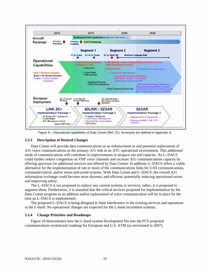
NASA/CR—2010-216326 19
Figure 9.—Operational capabilities of Data Comm (Ref. 21). Acronyms are defined in Appendix A.
3.3.3 Description of Desired Changes
Data Comm will provide data communications as an enhancement to and potential replacement of A/G voice communications as the primary A/G link in an ATC operational environment. This additional mode of communications will contribute to improvements in airspace use and capacity. An L–DACS could further reduce congestion on VHF voice channels and increase A/G communications capacity by offering spectrum for additional services not offered by Data Comm. In addition, L–DACS offers a viable alternative for the implementation of one or more of the communications links for UAS communications, command/control, and/or sense-and-avoid systems. With Data Comm and L–DACS, the overall A/G information exchange could become more dynamic and efficient, potentially reducing operational errors and improving safety.
The L–DACS is not proposed to replace any current systems or services; rather, it is proposed to augment them. Furthermore, it is assumed that the critical services proposed for implementation by the Data Comm program as an addition and/or replacement of voice communication will be in place by the time an L–DACS is implemented.
The proposed L–DACS is being designed to limit interference to the existing services and operations in the L-band. No operational changes are expected for the L-band incumbent systems.
3.3.4 Change Priorities and Roadmaps
Figure 10 demonstrates how the L-band system development fits into the FCS proposed communications evolutional roadmap for European and U.S. ATM (as envisioned in 2007).
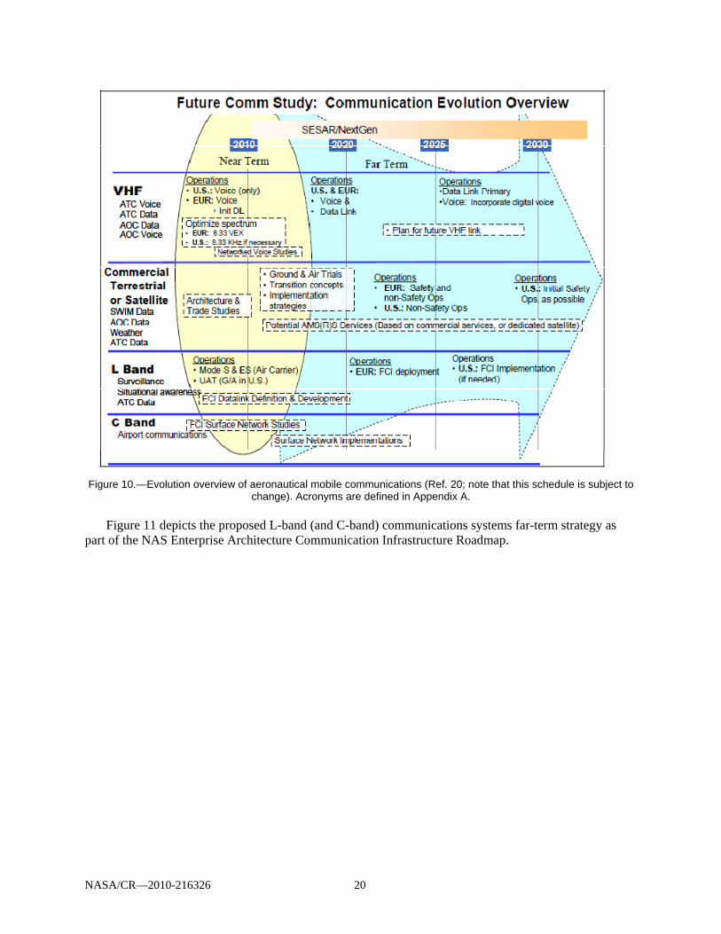
NASA/CR—2010-216326 20
Figure 10.—Evolution overview of aeronautical mobile communications (Ref. 20; note that this schedule is subject to
change). Acronyms are defined in Appendix A. Figure 11 depicts the proposed L-band (and C-band) communications systems far-term strategy as
part of the NAS Enterprise Architecture Communication Infrastructure Roadmap.
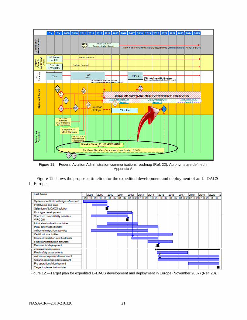
NASA/CR—2010-216326 21
Figure 11.—Federal Aviation Administration communications roadmap (Ref. 22). Acronyms are defined in
Appendix A. Figure 12 shows the proposed timeline for the expedited development and deployment of an L–DACS
in Europe.
Figure 12.—Target plan for expedited L–DACS development and deployment in Europe (November 2007) (Ref. 20).
NASA/CR—2010-216326 22
3.3.5 Assumptions and Constraints for L–DACS
Assumptions and constraints for this document follow:
The proposed L–DACS is assumed to provide an increase in overall A/G communications systems capacity by utilizing the new spectrum (i.e., not VHF).
As noted earlier, the scope of this ConUse and requirements document includes A/G and A/A communications.
L–DACS will be designed specifically for data communication. When finalized, the technology may support voice communications, but this feature is not considered a system requirement at this time.
As noted earlier, this document assumes that the data communications system developed as part of Data Comm will precede an L–DACS implementation and deployment.
Although some critical services are proposed, the L–DACS will also target noncritical services, such as weather advisory and aeronautical information services implemented as part of an airborne SWIM program. It will also target one or more UAS communications services.
Although the L–DACS ConUse and functional requirements developed for the document are largely technology independent, services selection and overall system requirements may change if and when additional or different data is available from proposed L–DACS interference testing and as a result of a final selection of one of the two L–DACS technologies under consideration as of the time of this report.
L–DACS is to be designed and implemented in a manner that will not disrupt other existing services operating in the L-band. Additional interference research and testing will determine if any operational constraints are to be imposed, such as limiting the number of users, the time of the day, duration, and other parameters.
Economic feasibility of an L–DACS, from the perspective of the ground infrastructure provider, was
evaluated at a top level during the FCS Phase II project (Ref. 23) based on the results of the earlier technology prescreening (FCS Phase I). The initial economic analysis that was conducted showed that a positive business case for an L-band system implementation could be achieved with a payback period of 4 years (Ref. 4). However, while the first order of magnitude cost estimate yielded positive results, the assumptions made during the analysis should be revisited at a later stage, when more details of a planned implementation are known. The analysis assumptions included consideration of coverage, system requirements, research and development, and operations and maintenance costs.
3.4 Proposed L–DACS System
3.4.1 Objectives and Scope
Consistent with the need to overcome the specific current communications systems problems and shortfalls discussed earlier, two additional primary drivers for a future radio system (FRS) are (1) to provide an appropriate communications infrastructure to support future air traffic growth and (2) to provide a consistent global solution to support the goal of seamless air traffic management (Ref. 5).
Accordingly, the proposed L–DACS component of the FRS aims to expand data communications capacity while being developed as a collaborative effort of the U.S. and European partners.
The proposed system will be designed and implemented to meet FAA objectives defined in the FAA NextGen solution sets. For example, the collaborative air traffic management (CATM) solution set focuses on delivering services to accommodate flight operator preferences to the maximum extent possible. One of the required capabilities of this set is providing real on-demand NAS information—time access to NAS status (operational improvement (OI) 103305).
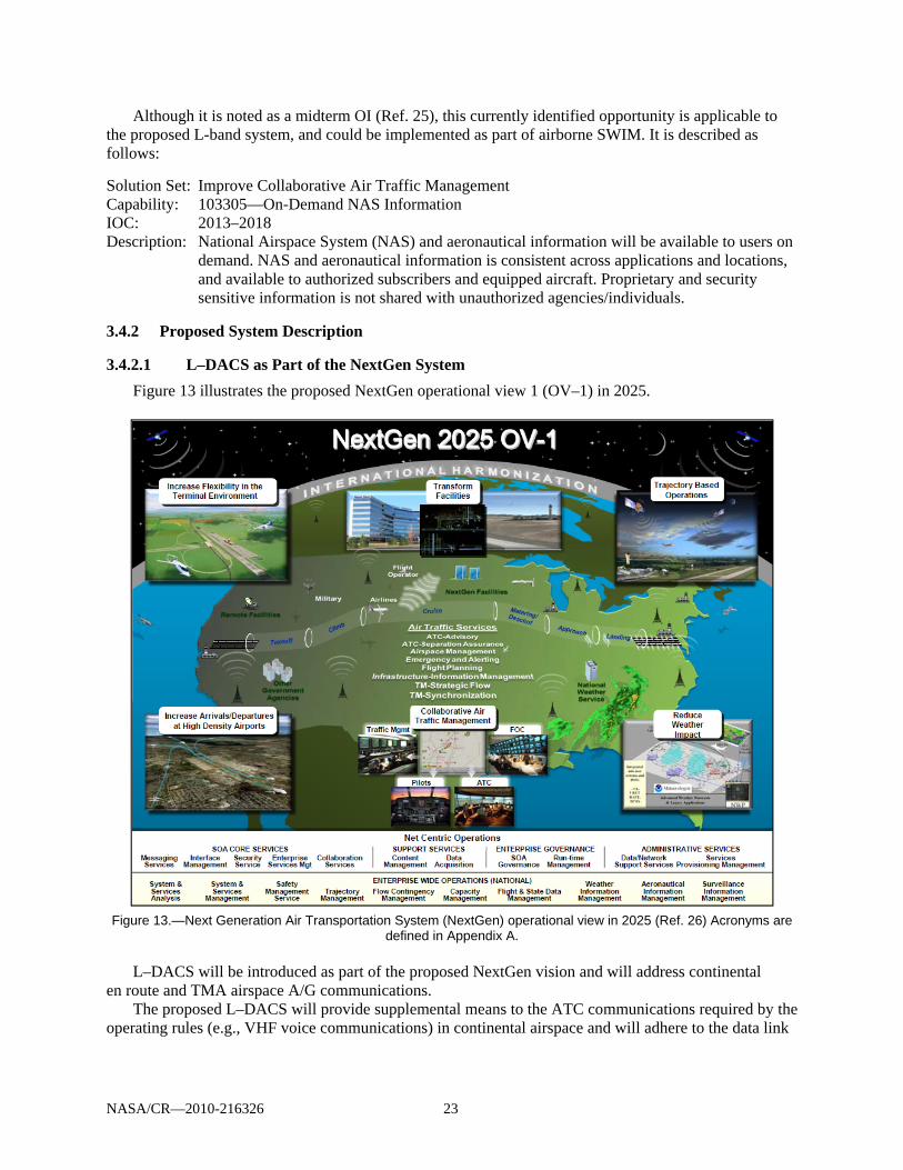
NASA/CR—2010-216326 23
Although it is noted as a midterm OI (Ref. 25), this currently identified opportunity is applicable to the proposed L-band system, and could be implemented as part of airborne SWIM. It is described as follows:
Solution Set: Improve Collaborative Air Traffic Management Capability: 103305—On-Demand NAS Information IOC: 2013–2018 Description: National Airspace System (NAS) and aeronautical information will be available to users on
demand. NAS and aeronautical information is consistent across applications and locations, and available to authorized subscribers and equipped aircraft. Proprietary and security sensitive information is not shared with unauthorized agencies/individuals.
3.4.2 Proposed System Description
3.4.2.1 L–DACS as Part of the NextGen System
Figure 13 illustrates the proposed NextGen operational view 1 (OV–1) in 2025.
Figure 13.—Next Generation Air Transportation System (NextGen) operational view in 2025 (Ref. 26) Acronyms are
defined in Appendix A. L–DACS will be introduced as part of the proposed NextGen vision and will address continental
en route and TMA airspace A/G communications. The proposed L–DACS will provide supplemental means to the ATC communications required by the
operating rules (e.g., VHF voice communications) in continental airspace and will adhere to the data link

NASA/CR—2010-216326 24
characteristics noted in “Safety and Performance Requirements Standard for Air Traffic Data Link Services in Continental Airspace (Continental SPR Standard)” (Ref. 14).
3.4.2.2 Proposed Operational Environment
Along with the “as-is” SV–2 views of the NAS developed by the FAA Air Traffic Organization (ATO) planning organization, were a series of different “to be” views providing separate views for the five information flow areas for the 2025 timeframe. Figure 14 presents a 2025 service view for the command-and-control function for the proposed NAS.
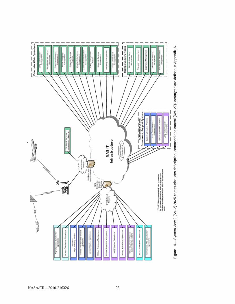
F
igur
e 1
4.—
Sys
tem
vie
w 2
(S
V–2
) 20
25 c
omm
unic
atio
ns d
esc
riptio
n: c
omm
and
and
co
ntro
l (R
ef. 2
7). A
cron
yms
are
def
ine
d in
Ap
pend
ix A
.
NASA/CR—2010-216326 25

NASA/CR—2010-216326 26
As noted in the NextGen ConOps (Ref. 2):
In the NextGen timeframe, demand for air transportation and other airspace services is expected to grow significantly from today’s levels in terms of passenger volume, amount of cargo shipped, and overall number of flights. With respect to air traffic, changes will occur not only in the number of flights but also in the characteristics of those flights. Figure 15 illustrates some of the potential variations in demand characteristics.
Figure 15.—Range of features in the NextGen system (Ref. 2).
In NextGen, aircraft are expected to have a wider range of capabilities than today and support varying levels of total system performance via onboard capabilities and associated crew training. Many aircraft will have the ability to perform airborne self-separation, spacing, and merging tasks and precisely navigate and execute 4DTs. Along with navigation accuracy, aircraft will have varying levels of cooperative surveillance performance via transmission and receipt of cooperative surveillance information, as well as the ability to observe and share weather information. In terms of flight operational performance, a wider range of capabilities regarding cruise speed, cruise altitudes, turn rates, climb and descent rates, stall speeds, noise, and emissions will exist. Aircraft without a resident pilot (e.g., UASs) will operate among traditional manned, piloted aircraft, and domestic supersonic cruise operations will also be more prevalent.
Aircraft operators are also expected to have a diverse range of capabilities and operating modes. Many operators will have sophisticated flight planning and fleet planning capabilities to manage their operations. Operating modes include all of today’s modes, such as traditional hub/spoke operations, point-to-point flights, military/civil training, and recreational flying. Operational demand may vary among highly structured flights
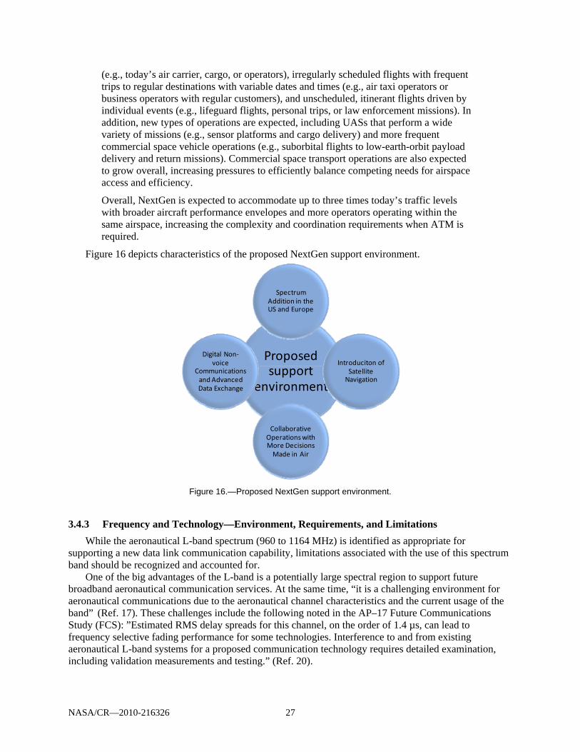
NASA/CR—2010-216326 27
(e.g., today’s air carrier, cargo, or operators), irregularly scheduled flights with frequent trips to regular destinations with variable dates and times (e.g., air taxi operators or business operators with regular customers), and unscheduled, itinerant flights driven by individual events (e.g., lifeguard flights, personal trips, or law enforcement missions). In addition, new types of operations are expected, including UASs that perform a wide variety of missions (e.g., sensor platforms and cargo delivery) and more frequent commercial space vehicle operations (e.g., suborbital flights to low-earth-orbit payload delivery and return missions). Commercial space transport operations are also expected to grow overall, increasing pressures to efficiently balance competing needs for airspace access and efficiency.
Overall, NextGen is expected to accommodate up to three times today’s traffic levels with broader aircraft performance envelopes and more operators operating within the same airspace, increasing the complexity and coordination requirements when ATM is required.
Figure 16 depicts characteristics of the proposed NextGen support environment.
Figure 16.—Proposed NextGen support environment.
3.4.3 Frequency and Technology—Environment, Requirements, and Limitations
While the aeronautical L-band spectrum (960 to 1164 MHz) is identified as appropriate for supporting a new data link communication capability, limitations associated with the use of this spectrum band should be recognized and accounted for.
One of the big advantages of the L-band is a potentially large spectral region to support future broadband aeronautical communication services. At the same time, “it is a challenging environment for aeronautical communications due to the aeronautical channel characteristics and the current usage of the band” (Ref. 17). These challenges include the following noted in the AP–17 Future Communications Study (FCS): ”Estimated RMS delay spreads for this channel, on the order of 1.4 µs, can lead to frequency selective fading performance for some technologies. Interference to and from existing aeronautical L-band systems for a proposed communication technology requires detailed examination, including validation measurements and testing.” (Ref. 20).
Proposed support
environment
Spectrum Addition in the US and Europe
Introduciton of Satellite Navigation
Collaborative Operations with More Decisions Made in Air
Digital Non‐voice
Communications and Advanced Data Exchange
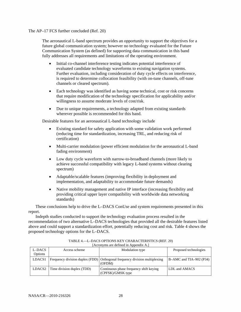
NASA/CR—2010-216326 28
The AP–17 FCS further concluded (Ref. 20)
The aeronautical L-band spectrum provides an opportunity to support the objectives for a future global communication system; however no technology evaluated for the Future Communication System (as defined) for supporting data communication in this band fully addresses all requirements and limitations of the operating environment.
Initial co-channel interference testing indicates potential interference of evaluated candidate technology waveforms to existing navigation systems. Further evaluation, including consideration of duty cycle effects on interference, is required to determine collocation feasibility (with on-tune channels, off-tune channels or cleared spectrum).
Each technology was identified as having some technical, cost or risk concerns that require modification of the technology specification for applicability and/or willingness to assume moderate levels of cost/risk.
Due to unique requirements, a technology adapted from existing standards wherever possible is recommended for this band.
Desirable features for an aeronautical L-band technology include
Existing standard for safety application with some validation work performed (reducing time for standardization, increasing TRL, and reducing risk of certification)
Multi-carrier modulation (power efficient modulation for the aeronautical L-band fading environment)
Low duty cycle waveform with narrow-to-broadband channels (more likely to achieve successful compatibility with legacy L-band systems without clearing spectrum)
Adaptable/scalable features (improving flexibility in deployment and implementation, and adaptability to accommodate future demands)
Native mobility management and native IP interface (increasing flexibility and providing critical upper layer compatibility with worldwide data networking standards)
These conclusions help to drive the L–DACS ConUse and system requirements presented in this report.
Indepth studies conducted to support the technology evaluation process resulted in the recommendation of two alternative L–DACS technologies that provided all the desirable features listed above and could support a standardization effort, potentially reducing cost and risk. Table 4 shows the proposed technology options for the L–DACS.
TABLE 4.—L–DACS OPTIONS KEY CHARACTERISTICS (REF. 20)
[Acronyms are defined in Appendix A.] L–DACS Options
Access scheme Modulation type Proposed technologies
LDACS1 Frequency division duplex (FDD) Orthogonal frequency division multiplexing (OFDM)
B–AMC and TIA–902 (P34)
LDACS2 Time division duplex (TDD) Continuous phase frequency shift keying (CPFSK)/GMSK type
LDL and AMACS

NASA/CR—2010-216326 29
Follow-on FCS activities will further characterize and evaluate the proposed technology solutions, validate performance, and lead to a single L–DACS technology recommendation.
3.4.4 User Impact
Users of the system will include service providers and airspace users of A/G communications: Safety and regularity of flight component
o Air traffic controllers on the ground and flight crews in the air o UASs
Commercial data transfer related to airline operations and provisions of services to passengers—addressed by service providers on the ground and flight crews and passengers in the air
Both civil and military users will utilize the system as related to the services offered. Growing requirements to use UAS in civilian airspace using AM(R)S and AMS(R)S frequency allocations adds a new layer of requirements and adds different type of users to an aeronautical system.
The introduction of an L-band system is expected to increase communications system capacity, thus allowing the addition of new services and expanding the user base. Figure 17 illustrates the effect of new system addition on the user base.
It should be noted that the relationship between the capacity demand and changes in the user base are viewed as a cycle of events. The proposed introduction of an L-band system will increase the overall capacity of the system and open up opportunities for addition of data services not provided under the Data Comm. Many of those, most notably services associated with the Airborne SWIM program, will provide for the wider system use. Not only more users would be expected to take advantage of the new data communications capabilities, the types of users allowed to participate will change as well.
Figure 17.—Communication system capacity demand and user base changes.
As more data services are introduced and become part of day-to-day operations, the demand for
additional services, and therefore capacity, is expected to grow. An introduction of a new frequency band, such as an L-band, in addition to the VHF frequencies supporting the existing voice and data communications services, will alleviate long-term capacity problems. The expanded use of advanced technologies in general and L–DACS in particular, along with increased capacity, is expected to improve aviation safety and enhance operational efficiency for NAS users. The continued migration from a NAS based on a ground infrastructure and voice communication to a system that encompasses both ground and airborne components and utilizes the exchange of digital data as the primary type of communication, will “support the human in doing what they do best—choosing alternatives and making decisions, while the technology accomplishes what it can do best—the acquisition, compilation, evaluation and exchange of information” (Ref. 2).
Introduction of new services
Wider user base
Change in type and number of
users
Need for more data services
Increased system capacity

NASA/CR—2010-216326 30
NextGen communications systems will enable users to play a more active role in each of the NAS service areas:
NAS management (strategic flow and resource management): SWIM capability will enable
stakeholders’ access to relevant information. Users will become key participants in the planning of traffic flow management and will utilize a comprehensive information exchange process to improve flight operations planning according to capacity and traffic conditions to minimize congestion and delays.
Flight planning and emergency alerting services: Users will have interactive flight planning capabilities with an immediate access to real-time data. User-preferred routing will become available to properly equipped aircraft for both domestic and international flights.
Surface operations: Increased data-exchange capabilities will provide more users at more airports with flight clearances, airports information, positions of other aircraft, taxi routes, and weather conditions (current, forecast, hazardous). Users will have improved real-time planning with continuous update of the flight profile.
Arrival/departure and en route: A/G data exchange will enable more active flight deck participation in the decisionmaking process. Users will utilize data, such as ATC clearances, current and forecast weather, notices to airmen and hazardous weather warnings, updated charts, current weather, special use airspace status, and other required data.
Oceanic: A/G communication via L–DACS will not be provided in oceanic airspace.
3.4.5 Operational Policies and Constraints
Operational aspects of aeronautical communications are changing with an increased emphasis on safety and cost reduction achieved via increased automation, efficiency, delays reduction, and other improvements.
General issues such as cost, spectrum availability, technology choice, and standards development, as well as logistics of system rollout will all influence operational policies and constraints.
The NextGen ConOps document details operational policy issues that would affect the NextGen system. To support the proposed L–DACS development and implementation, policies need to be developed in the following areas:
International and domestic regulations Safety management standards Processes to streamline certification and reduce costs for aircraft and ground equipment Privacy and liability legal concerns related to information sharing Communications priority and congestion relief (e.g., market-driven vs. aircraft type) Government role versus private sector role Financing and maintenance responsibilities
3.5 L–DACS Concepts of Use
3.5.1 RTCA National Airspace System Concepts of Operations Guidance
As noted in Section 2, the L–DACS ConUse were defined based on guidance and information provided by several higher order ConOps. A key NAS ConOps source driving the L–DACS ConUse is the RTCA NAS ConOps (Ref. 1). Appendix A presents a comprehensive listing derived from the RTCA NAS ConOps of future communications concepts to enable transfer of the following NAS information types:
Surveillance Weather

NASA/CR—2010-216326 31
Flight planning Aeronautical information Resource management
3.5.2 Data Comm Operational Scenarios
Operational scenarios can illustrate how proposed system capabilities could be used in an operational environment. The scenarios can demonstrate how the services offered by the new communications system could help to
Minimize operational errors, including those resulting from misunderstood instructions and read-
back errors Improve efficiency Provide further automation of traffic control Enable more decisions made off the ground The Data Comm FPR provides an extensive listing of operational scenarios envisioned to be enabled
by the data communications system. These scenarios also would be generally applicable to an L–DACS, implementation.
3.5.3 Proposed Services
3.5.3.1 Air Traffic Services
Reference 11 classifies all of the COCR ATS data services as safety critical. It further identifies services that are not planned to be implemented by Data Comm through Segment 3, and identifies them as possible candidates for implementation via C-band and/or L-DACS. It must be stressed that both C-band and L–DACS are being developed for the future communications infrastructure to accommodate safety and regularity of flight services. These are designed to operate over aviation protected spectrum, so any COCR ATS service could be allowed to be implemented via one or the other of these links (as appropriate).
As described earlier, this document focuses on the COCR ATS data services that are not expected to be provided by Data Comm through Segment 3, proposed as candidates for L–DACS as listed below.
Flight information services
– Data link operational route information service (D–ORIS) – Data link operational terminal information service (D–OTIS) – Data link surface information and guidance (D–SIG) – Data link runway visual range (D–RVR) while airborne – Wake vortex (WAKE) – Flight plan consistency (FLIPCY) – System access parameter (SAP) – Pilot preferences downlink (PPD)
Weather advisory service – Data link significant meteorological information (D–SIGMET)
Advisory service – Dynamic route availability (DYNAV)
Emergency information service – Urgent contact (URCO), if in conjunction with other more routine services
A/A service – Air-to-air self separation (AIRSEP)

NASA/CR—2010-216326 32
COCR (Ref. 2) contains the description of the above services. Additional data services that may be provided via L–DACS could be identified as NextGen and SESAR progress.
3.5.3.2 Unmanned Aircraft System (UAS) Suitable Services
Services specific to the operation of UAS in the NAS and potentially suitable for implementation via an L–DACS would include the following:
Pilot/UA control links, including telecommand and telemetry Pilot/UA NavAids data exchanges Relaying ATC voice messages to and from UA pilots Relaying ATS data messages to and from UA pilots6 UA-to-pilot downlinking of nonpayload target-track data UA-to-pilot downlinking of data from UA-borne weather radars UA-to-pilot downlinking of safety-related video data from UA to pilots UA-to-pilot downlinking of safety-related sense and avoid automated decisionmaking from UA
to pilots Section 6.0 contains more detail on UAS-related services.
3.5.3.3 Airborne System Wide Information Management (SWIM) Suitable Services
SWIM, an FAA technology program designed to facilitate sharing of ATM system information (airport operational status, weather information, flight data, status of special-use airspace, and NAS restrictions), can be implemented via G/G, A/G, and A/A communications infrastructure components. Each of these components would enable efficient data exchange between authorized users in the respective domain. An L–DACS could provide means for the A/A and A/G data transfer.
An implementation of the proposed L-band system would facilitate meeting the primary objective of the SWIM program: that is, to improve the FAA’s ability to manage the efficient flow of information through the NAS. When used to enable Airborne SWIM capabilities, an L-band system could be designed to assure that its use provides the following desired SWIM features:
Reduced costs for NAS users to acquire NAS data and exchange information Increased shared situational awareness among the NAS user community FAA-compliant secure data exchange among the NAS user community Figure 18 shows how Airborne SWIM (with the communication links potentially provided over the
L-band) fits in the overall FAA A/G communications plan and illustrates interactions of SWIM elements with the other NextGen programs, such as automatic dependence surveillance–broadcast (ADS–B) and Data Comm.
6 Such as the services presented in the COCR, including those listed above in Section 4.2.
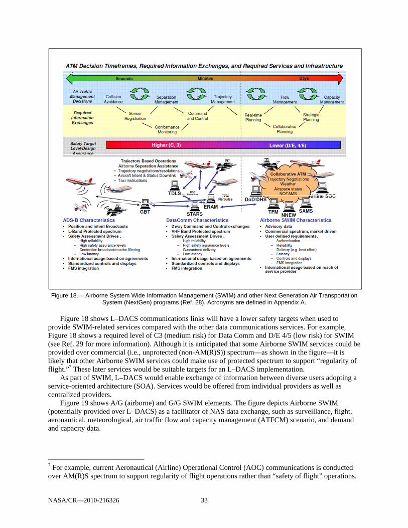
NASA/CR—2010-216326 33
Figure 18.— Airborne System Wide Information Management (SWIM) and other Next Generation Air Transportation
System (NextGen) programs (Ref. 28). Acronyms are defined in Appendix A.
Figure 18 shows L–DACS communications links will have a lower safety targets when used to provide SWIM-related services compared with the other data communications services. For example, Figure 18 shows a required level of C3 (medium risk) for Data Comm and D/E 4/5 (low risk) for SWIM (see Ref. 29 for more information). Although it is anticipated that some Airborne SWIM services could be provided over commercial (i.e., unprotected (non-AM(R)S)) spectrum—as shown in the figure—it is likely that other Airborne SWIM services could make use of protected spectrum to support “regularity of flight.”7 These later services would be suitable targets for an L–DACS implementation.
As part of SWIM, L–DACS would enable exchange of information between diverse users adopting a service-oriented architecture (SOA). Services would be offered from individual providers as well as centralized providers.
Figure 19 shows A/G (airborne) and G/G SWIM elements. The figure depicts Airborne SWIM (potentially provided over L–DACS) as a facilitator of NAS data exchange, such as surveillance, flight, aeronautical, meteorological, air traffic flow and capacity management (ATFCM) scenario, and demand and capacity data.
7 For example, current Aeronautical (Airline) Operational Control (AOC) communications is conducted over AM(R)S spectrum to support regularity of flight operations rather than “safety of flight” operations.
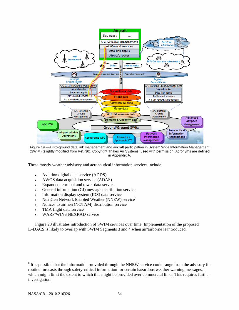
NASA/CR—2010-216326 34
Figure 19.—Air-to-ground data link management and aircraft participation in System Wide Information Management (SWIM) (slightly modified from Ref. 30). Copyright Thales Air Systems; used with permission. Acronyms are defined
in Appendix A. These mostly weather advisory and aeronautical information services include
Aviation digital data service (ADDS) AWOS data acquisition service (ADAS) Expanded terminal and tower data service General information (GI) message distribution service Information display system (IDS) data service NextGen Network Enabled Weather (NNEW) service8 Notices to airmen (NOTAM) distribution service TMA flight data service WARP/WINS NEXRAD service
Figure 20 illustrates introduction of SWIM services over time. Implementation of the proposed
L–DACS is likely to overlap with SWIM Segments 3 and 4 when air/airborne is introduced.
8 It is possible that the information provided through the NNEW service could range from the advisory for routine forecasts through safety-critical information for certain hazardous weather warning messages, which might limit the extent to which this might be provided over commercial links. This requires further investigation.
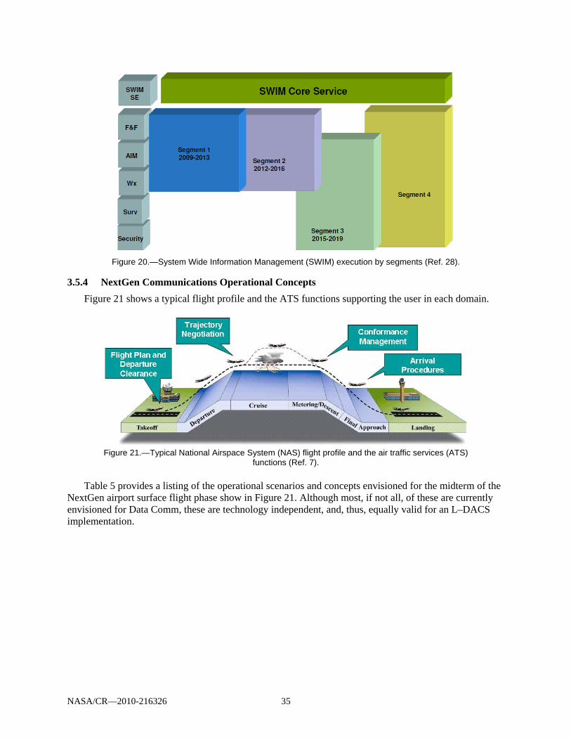
NASA/CR—2010-216326 35
Figure 20.—System Wide Information Management (SWIM) execution by segments (Ref. 28).
3.5.4 NextGen Communications Operational Concepts
Figure 21 shows a typical flight profile and the ATS functions supporting the user in each domain.
Figure 21.—Typical National Airspace System (NAS) flight profile and the air traffic services (ATS) functions (Ref. 7).
Table 5 provides a listing of the operational scenarios and concepts envisioned for the midterm of the
NextGen airport surface flight phase show in Figure 21. Although most, if not all, of these are currently envisioned for Data Comm, these are technology independent, and, thus, equally valid for an L–DACS implementation.

NASA/CR—2010-216326 36
TABLE 5.—NEXT GENERATION AIR TRANSPORTATION SYSTEM (NextGen) MIDTERM OPERATIONAL
CONCEPTS FOR THE AIRPORT SURFACE Phase of flight NextGen midterm communications operational concept (from Ref. 10)
Flight planning Access to flight planning information will be available to authorized users via a secure network and will include a publish/subscribe capability so that users can receive automatic updates when conditions change along the proposed flight path.
Push back, taxi, and departure
As the time for the flight approaches, the final flight path agreement will be delivered as a data message to pilots who access the agreement before beginning the flight.
Climb and cruise Data communications will increase efficiency by providing routine and strategic information to the pilot and automating certain routine tasks for both the pilot and controller.
A decreased number of voice communications also will reduce radio frequency congestion and eliminate verbal miscommunication—a great safety improvement that will reduce operational errors.
Providing changes to radio frequencies and other information, such as local barometric pressure and required weather advisories, by data communications link can also reduce errors.
When weather impacts numerous flights, clearances for data communications capable aircraft can be sent all at once, increasing controller and operator efficiency.
If potential conflicts with other aircraft or other constraints, such as weather or homeland security interventions, develop along the path, the NextGen system will identify the problem and provide recommended path trajectory or speed changes to eliminate the conflict. The controller will send the pilot the proposed change via a data communications link, if the aircraft is equipped.
When re-routing is required, the flight can be assigned precision offsets to the published route. These offsets will become a way of turning a single published route into a “multi-lane highway.” Use of offsets will increase capacity in a section of airspace. These reroutes can be tailored for each flight. Since the final agreement will be reached via data messaging, complex reroutes can be more detailed than those constrained by the limitations of voice communications and can reduce one source of error in communications.
As weather and wind conditions change above the ocean, both individual reroutes and changes to the entire route structure will be managed via a data communications link.
Descent and approach Information such as proposed arrival time, sequencing and route assignments will be exchanged with the aircraft via a data communications link to negotiate a final flight path.
Landing, taxi, arrival Before the flight lands, both the preferred taxiway to be used for exiting the runway and the taxi path to the assigned parking will be available to the flight crew via a data communications link.
3.5.5 Communications Operational Services and Concepts Based on Flight Domain
Operational concepts can also be defined according to the different geographic flight domains, defined as follows (from Ref. 31):
Airport (APT): airport surface/immediate vicinity of the airport. Terminal maneuvering area (TMA): airspace surrounding an airport to about 50 nautical miles
from the center of an airport. En route (ENR): airspace that surrounds the TMA domain. This is the continental or domestic
airspace used by ATC for the cruise portion of a flight. Oceanic, remote, polar (ORP): same as the ENR domain, but in geographical areas generally
outside of domestic airspace. Autonomous operations area (AOA): airspace associated with autonomous operations where
aircraft self-separate.
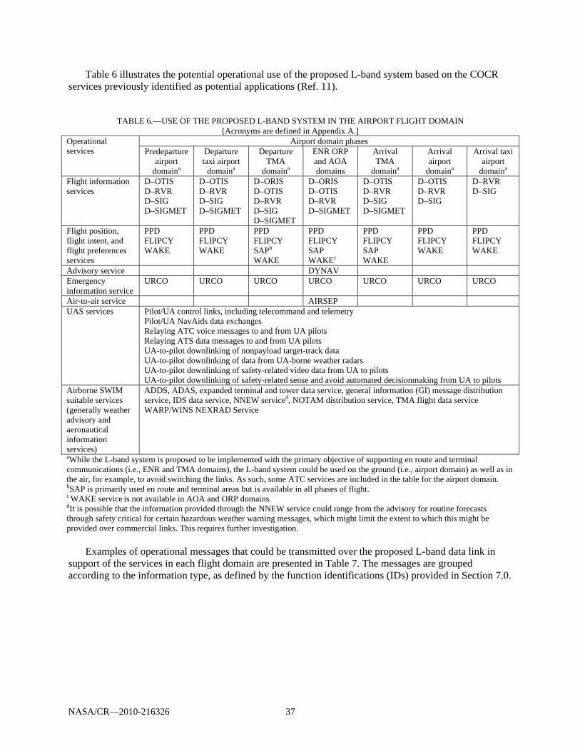
NASA/CR—2010-216326 37
Table 6 illustrates the potential operational use of the proposed L-band system based on the COCR services previously identified as potential applications (Ref. 11).
TABLE 6.—USE OF THE PROPOSED L-BAND SYSTEM IN THE AIRPORT FLIGHT DOMAIN [Acronyms are defined in Appendix A.]
Operational services
Airport domain phases Predeparture
airport domaina
Departure taxi airport
domaina
Departure TMA
domaina
ENR ORP and AOA domains
Arrival TMA
domaina
Arrival airport
domaina
Arrival taxi airport
domaina Flight information services
D–OTIS D–RVR D–SIG D–SIGMET
D–OTIS D–RVR D–SIG D–SIGMET
D–ORIS D–OTIS D–RVR D–SIG D–SIGMET
D–ORIS D–OTIS D–RVR D–SIGMET
D–OTIS D–RVR D–SIG D–SIGMET
D–OTIS D–RVR D–SIG
D–RVR D–SIG
Flight position, flight intent, and flight preferences services
PPD FLIPCY WAKE
PPD FLIPCY WAKE
PPD FLIPCY SAPb
WAKE
PPD FLIPCY SAP WAKEc
PPD FLIPCY SAP WAKE
PPD FLIPCY WAKE
PPD FLIPCY WAKE
Advisory service DYNAV Emergency information service
URCO URCO URCO URCO URCO URCO URCO
Air-to-air service AIRSEP UAS services Pilot/UA control links, including telecommand and telemetry
Pilot/UA NavAids data exchanges Relaying ATC voice messages to and from UA pilots Relaying ATS data messages to and from UA pilots UA-to-pilot downlinking of nonpayload target-track data UA-to-pilot downlinking of data from UA-borne weather radars UA-to-pilot downlinking of safety-related video data from UA to pilots UA-to-pilot downlinking of safety-related sense and avoid automated decisionmaking from UA to pilots
Airborne SWIM suitable services (generally weather advisory and aeronautical information services)
ADDS, ADAS, expanded terminal and tower data service, general information (GI) message distribution service, IDS data service, NNEW serviced, NOTAM distribution service, TMA flight data service WARP/WINS NEXRAD Service
aWhile the L-band system is proposed to be implemented with the primary objective of supporting en route and terminal communications (i.e., ENR and TMA domains), the L-band system could be used on the ground (i.e., airport domain) as well as in the air, for example, to avoid switching the links. As such, some ATC services are included in the table for the airport domain. bSAP is primarily used en route and terminal areas but is available in all phases of flight. c WAKE service is not available in AOA and ORP domains. dIt is possible that the information provided through the NNEW service could range from the advisory for routine forecasts through safety critical for certain hazardous weather warning messages, which might limit the extent to which this might be provided over commercial links. This requires further investigation.
Examples of operational messages that could be transmitted over the proposed L-band data link in support of the services in each flight domain are presented in Table 7. The messages are grouped according to the information type, as defined by the function identifications (IDs) provided in Section 7.0.

NASA/CR—2010-216326 38
TABLE 7.—EXAMPLE L-BAND DATA LINK MESSAGES
Information type (including corresponding function ID)
Message examples
Transceive air traffic services (ATS) to airborne aircraft message L.1.1.1.1
Contract requesting data Contract acknowledgements Operational terminal information service (OTIS) reports, addressed or broadcast communications Operational en route information service (ORIS) reports, addressed or broadcast communications Significant meteorological information (SIGMET) reports, addressed or broadcast communications, event basis only Airport data to be displayed on board (data link surface information and guidance, D–SIG) Runway visual range (RVR) information, addressed or broadcast communications Available alternative routes (dynamic route availability, DYNAV), addressed communication Urgent contact message (URCO), addressed and/or broadcast communications
Transceive airborne aircraft to ATS message L.1.1.2.1
Requests (i.e., demand, periodic, or event contract) for reports Contract acknowledgements Current and periodic position (flight plan consistency, FLIPCY), addressed communications Meteorological data (FLIPCY), addressed communications Ground speed (FLIPCY), addressed communications Indicated heading, indicated air speed or mach, vertical rate, selected level, and wind vector (system access parameters, SAP), addressed communications Broadcast of aircraft wake turbulence (WAKE) characteristics (e.g., aircraft type, weight, and flap and speed settings) Flight limitations (e.g., maximum acceptable flight level) (pilot preferences downlink, PPD), addressed communications Pilot flight preferences (PPD), addressed communications Flight plan modification requests (e.g., desired route or speed limitations) (PPD), addressed communications URCO, addressed and/or broadcast communications
Transceive ATS to on-ground aircraft message L.1.1.1.2
Contract requesting data Contract acknowledgements OTIS reports, addressed or broadcast communications ORIS reports, addressed or broadcast communications SIGMET reports, addressed or broadcast communications, event basis only Airport data to be displayed on board (D–SIG) RVR information, addressed or broadcast communications Available alternative routes (DYNAV), addressed communication URCO, addressed and/or broadcast communications

NASA/CR—2010-216326 39
TABLE 7.—EXAMPLE L-BAND DATA LINK MESSAGES Information type (including
corresponding function ID)
Message examples
Transceive on-ground aircraft to ATS message L.1.1.2.2
Requests (i.e., demand, periodic, or event contract) for reports Contract acknowledgements Current and periodic position (FLIPCY), addressed communications Meteorological data (FLIPCY), addressed communications Ground speed (FLIPCY), addressed communications Indicated heading, indicated air speed or match, vertical rate, selected level, and wind vector (SAP), addressed communications Broadcast of WAKE characteristics (e.g., aircraft type, weight, and flap and speed settings) Flight limitations (e.g., maximum acceptable flight level) (PPD), addressed communications Pilot flight preferences (PPD), addressed communications Flight plan modification requests (e.g., desired route or speed limitations) (PPD), addressed communications URCO, addressed and/or broadcast communications
Transceive airborne aircraft to airborne aircraft message L.1.1.3.1
Trajectory intent exchange (air-to-air self-separation, AIRSEP), addressed and/or broadcast communications. Conflict negotiation (AIRSEP), addressed and/or broadcast communications. Resolution accept/confirmation
3.5.6 L–DACS Operational Concepts Derived from the COCR
Table 8 shows examples of operational scenarios for the proposed L-band system according to specific services identified earlier (Ref. 11) as proposed L–DACS applications (services that are not planned to be implemented by Data Comm through Segment 3). The scenarios are a subset of those provided in COCR Version 2.0 (Ref. 5).
Refer to Section 6 for ConUse and operational scenarios applicable to UAS.
TABLE 8.—EXAMPLE OPERATIONAL SCENARIOS
Flight domain Communication scenarios
Pre-departure airport domain
• The flight crew initiates a request for a data link operational terminal information service (D–OTIS) contract for the departure airfield. The flight information service (FIS) system response provides all relevant information for the weather, Automatic Terminal Information Service (ATIS), and field conditions, plus the local Notices to Airmen (NOTAMs).
• In low-visibility conditions, the flight crew may also use the data link runway visual range (D–RVR) service to request RVR information for the departure and the destination airports. For data-link-equipped aircraft preparing to taxi, the current graphical picture of the ground operational environment is uplinked and loaded using the data link surface information guidance (D–SIG) service.
• The flight crew specifies preferences that should be considered by the controllers using the pilot preferences downlink (PPD) service.
Departure terminal maneuvering area (TMA) domain
• The system access parameters (SAP) service is initiated by the air traffic service unit (ATSU) automation system, and the downlinked information is provided to the various ground components (e.g., for smoothing of trackers) or on request for display of parameters to controllers. The ATSU automation system monitors the aircraft behavior in accordance with the given clearances. The tracking system issues warnings to the executive controller in case of noncompliance. The executive controller intervenes if the situation requires action. The tracking system uses the automatic dependent surveillance (ADS) and radar data to monitor whether the aircraft performance is in accordance with the ground-predicted trajectory and updates the trajectory where necessary.

NASA/CR—2010-216326 40
TABLE 8.—EXAMPLE OPERATIONAL SCENARIOS
Flight domain Communication scenarios
En route, ocean, remote, polar (ORP) and autonomous operations area (AOA) domains
• The ATSU automation system confirms/sets the exit/entry conditions with the sectors in the en route phase. At each entry into a subsequent ATSU, FLIPCY is performed to verify the flight management system route against what is held in the ATSU flight data processing system.
• Planning controller indicating that moderate to severe turbulence may be expected over this portion of the flight. This information is sent to the aircraft via the data link significant meteorological information (D–SIGMET) service. A new network connection is established between the aircraft and the oceanic/remote domain ground system before the connection with the en route domain ground system is released.
• The planning controller analyses interactions with other aircraft that are reported to him/her by the conflict probe system. The planning controller probes “what-if” solutions for interactions. The conflict probe system may offer alternatives to the existing route, the planning controller assesses these alternatives, and the alternatives are provided via the dynamic route availability (DYNAV) service for flight crew assessment. The planning controller enters the flight-crew-selected alternative and updates the flight trajectory in the ATSU automation system. The flight crew flies the aircraft according to the instructions given. The ATSU automation system recognizes the aircraft’s position relative to exiting the ATSU, compiles a data link operational en route information service (D–ORIS) report specific to the remaining portion of the area to be over-flown, and sends it to the aircraft.
Arrival TMA domain
• The system updates arrival manager (AMAN) with changes to the arrival sequence. AMAN calculates constraints by taking into account the actual traffic situation and makes the information (time to lose, gain, or hold) available to the concerned planning controller and executive controllers in upstream sectors/ATSUs. If required, the conflict probe system calculates a conflict-free alternative trajectory for the flight to comply with the AMAN constraints. The planning controller of the receiving sector checks the PPD service information to see if the conflict probe system-provided trajectory could be improved with these preferences. The planning controller accepts the proposal and coordinates the sending of the ACL instruction with the Executive Controller. Based on the equipage and flight crew qualification information contained in the flight plan and data obtained via SAP and PPD, the Executive Controller determines which aircraft may execute a spacing application and issues merging and spacing clearances to those aircraft via ACL. (ACL is not proposed to be supported by L–DACS)
• The ATSU automation generates a D–SIG of the arrival airport surface. The D–SIG surface map is communicated in advance o the landing clearance so that the Flight Crew can determine any impacts to its configuration.
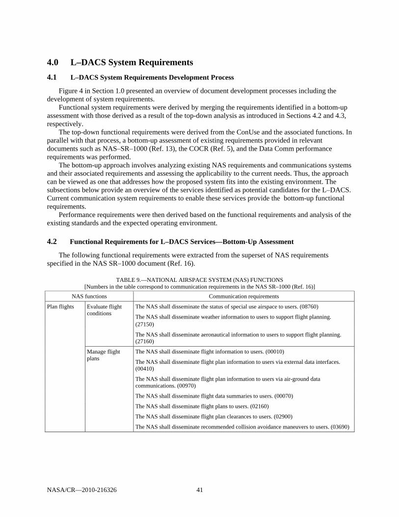
NASA/CR—2010-216326 41
4.0 L–DACS System Requirements
4.1 L–DACS System Requirements Development Process
Figure 4 in Section 1.0 presented an overview of document development processes including the development of system requirements.
Functional system requirements were derived by merging the requirements identified in a bottom-up assessment with those derived as a result of the top-down analysis as introduced in Sections 4.2 and 4.3, respectively.
The top-down functional requirements were derived from the ConUse and the associated functions. In parallel with that process, a bottom-up assessment of existing requirements provided in relevant documents such as NAS–SR–1000 (Ref. 13), the COCR (Ref. 5), and the Data Comm performance requirements was performed.
The bottom-up approach involves analyzing existing NAS requirements and communications systems and their associated requirements and assessing the applicability to the current needs. Thus, the approach can be viewed as one that addresses how the proposed system fits into the existing environment. The subsections below provide an overview of the services identified as potential candidates for the L–DACS. Current communication system requirements to enable these services provide the bottom-up functional requirements.
Performance requirements were then derived based on the functional requirements and analysis of the existing standards and the expected operating environment.
4.2 Functional Requirements for L–DACS Services—Bottom-Up Assessment
The following functional requirements were extracted from the superset of NAS requirements specified in the NAS SR–1000 document (Ref. 16).
TABLE 9.—NATIONAL AIRSPACE SYSTEM (NAS) FUNCTIONS
[Numbers in the table correspond to communication requirements in the NAS SR–1000 (Ref. 16)] NAS functions Communication requirements
Plan flights Evaluate flight conditions
The NAS shall disseminate the status of special use airspace to users. (08760)
The NAS shall disseminate weather information to users to support flight planning. (27150)
The NAS shall disseminate aeronautical information to users to support flight planning. (27160)
Manage flight plans
The NAS shall disseminate flight information to users. (00010)
The NAS shall disseminate flight plan information to users via external data interfaces. (00410)
The NAS shall disseminate flight plan information to users via air-ground data communications. (00970)
The NAS shall disseminate flight data summaries to users. (00070)
The NAS shall disseminate flight plans to users. (02160)
The NAS shall disseminate flight plan clearances to users. (02900)
The NAS shall disseminate recommended collision avoidance maneuvers to users. (03690)
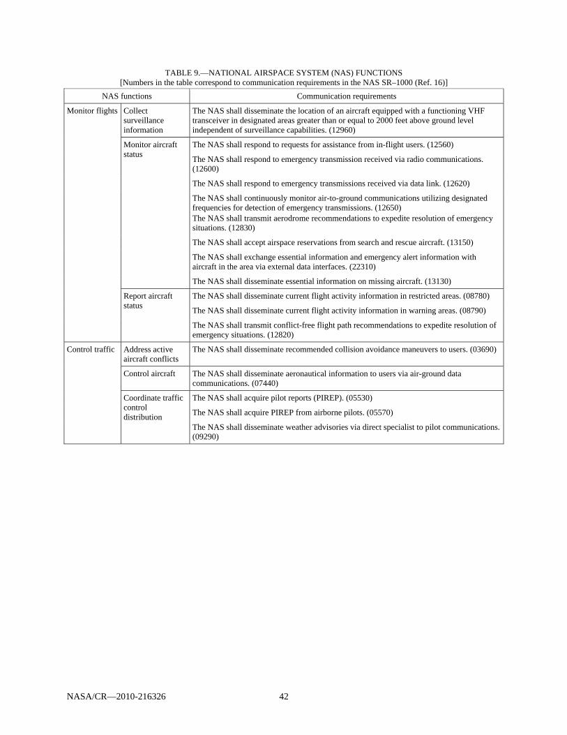
NASA/CR—2010-216326 42
TABLE 9.—NATIONAL AIRSPACE SYSTEM (NAS) FUNCTIONS [Numbers in the table correspond to communication requirements in the NAS SR–1000 (Ref. 16)]
NAS functions Communication requirements
Monitor flights Collect surveillance information
The NAS shall disseminate the location of an aircraft equipped with a functioning VHF transceiver in designated areas greater than or equal to 2000 feet above ground level independent of surveillance capabilities. (12960)
Monitor aircraft status
The NAS shall respond to requests for assistance from in-flight users. (12560)
The NAS shall respond to emergency transmission received via radio communications. (12600)
The NAS shall respond to emergency transmissions received via data link. (12620)
The NAS shall continuously monitor air-to-ground communications utilizing designated frequencies for detection of emergency transmissions. (12650) The NAS shall transmit aerodrome recommendations to expedite resolution of emergency situations. (12830)
The NAS shall accept airspace reservations from search and rescue aircraft. (13150)
The NAS shall exchange essential information and emergency alert information with aircraft in the area via external data interfaces. (22310)
The NAS shall disseminate essential information on missing aircraft. (13130)
Report aircraft status
The NAS shall disseminate current flight activity information in restricted areas. (08780)
The NAS shall disseminate current flight activity information in warning areas. (08790)
The NAS shall transmit conflict-free flight path recommendations to expedite resolution of emergency situations. (12820)
Control traffic Address active aircraft conflicts
The NAS shall disseminate recommended collision avoidance maneuvers to users. (03690)
Control aircraft The NAS shall disseminate aeronautical information to users via air-ground data communications. (07440)
Coordinate traffic control distribution
The NAS shall acquire pilot reports (PIREP). (05530)
The NAS shall acquire PIREP from airborne pilots. (05570)
The NAS shall disseminate weather advisories via direct specialist to pilot communications. (09290)
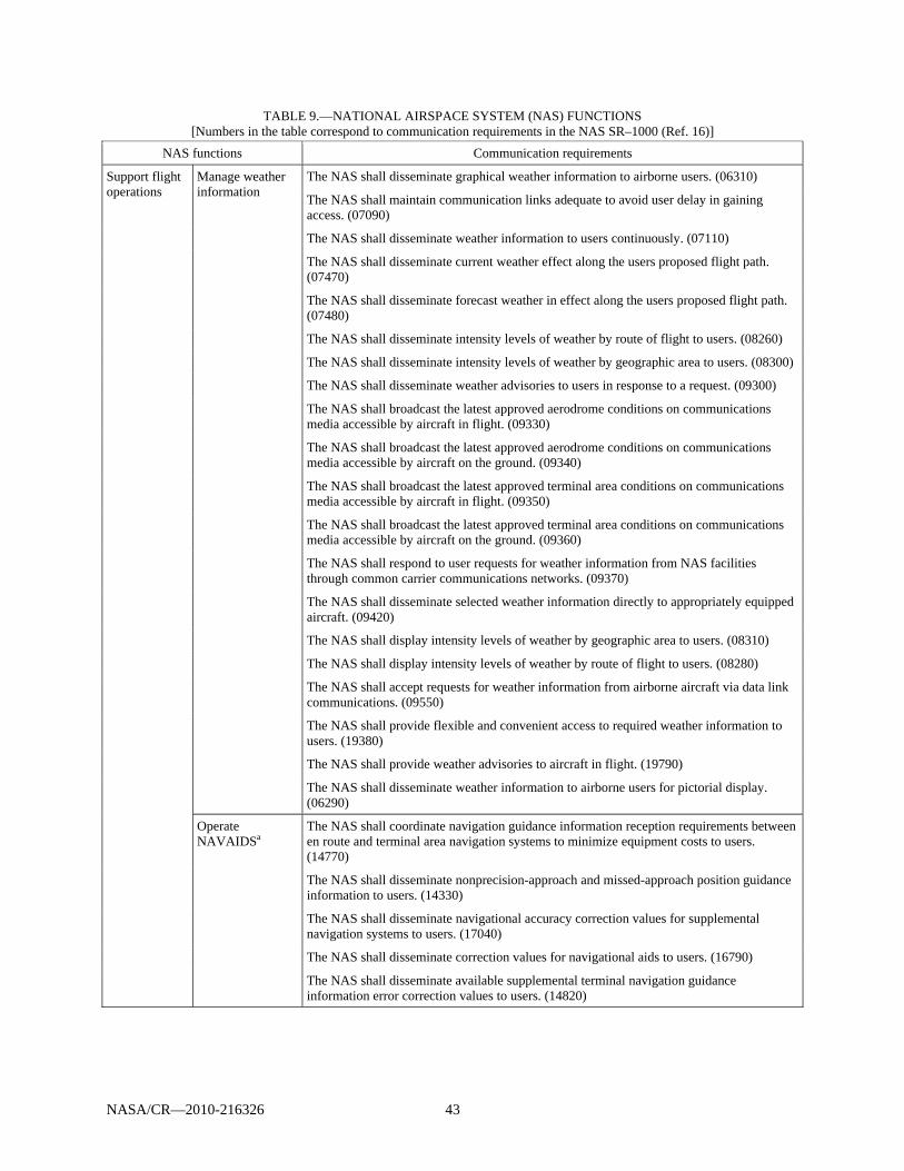
NASA/CR—2010-216326 43
TABLE 9.—NATIONAL AIRSPACE SYSTEM (NAS) FUNCTIONS [Numbers in the table correspond to communication requirements in the NAS SR–1000 (Ref. 16)]
NAS functions Communication requirements
Support flight operations
Manage weather information
The NAS shall disseminate graphical weather information to airborne users. (06310)
The NAS shall maintain communication links adequate to avoid user delay in gaining access. (07090)
The NAS shall disseminate weather information to users continuously. (07110)
The NAS shall disseminate current weather effect along the users proposed flight path. (07470)
The NAS shall disseminate forecast weather in effect along the users proposed flight path. (07480)
The NAS shall disseminate intensity levels of weather by route of flight to users. (08260)
The NAS shall disseminate intensity levels of weather by geographic area to users. (08300)
The NAS shall disseminate weather advisories to users in response to a request. (09300)
The NAS shall broadcast the latest approved aerodrome conditions on communications media accessible by aircraft in flight. (09330)
The NAS shall broadcast the latest approved aerodrome conditions on communications media accessible by aircraft on the ground. (09340)
The NAS shall broadcast the latest approved terminal area conditions on communications media accessible by aircraft in flight. (09350)
The NAS shall broadcast the latest approved terminal area conditions on communications media accessible by aircraft on the ground. (09360)
The NAS shall respond to user requests for weather information from NAS facilities through common carrier communications networks. (09370)
The NAS shall disseminate selected weather information directly to appropriately equipped aircraft. (09420)
The NAS shall display intensity levels of weather by geographic area to users. (08310)
The NAS shall display intensity levels of weather by route of flight to users. (08280)
The NAS shall accept requests for weather information from airborne aircraft via data link communications. (09550)
The NAS shall provide flexible and convenient access to required weather information to users. (19380)
The NAS shall provide weather advisories to aircraft in flight. (19790)
The NAS shall disseminate weather information to airborne users for pictorial display. (06290)
Operate NAVAIDSa
The NAS shall coordinate navigation guidance information reception requirements between en route and terminal area navigation systems to minimize equipment costs to users. (14770)
The NAS shall disseminate nonprecision-approach and missed-approach position guidance information to users. (14330)
The NAS shall disseminate navigational accuracy correction values for supplemental navigation systems to users. (17040)
The NAS shall disseminate correction values for navigational aids to users. (16790)
The NAS shall disseminate available supplemental terminal navigation guidance information error correction values to users. (14820)

NASA/CR—2010-216326 44
TABLE 9.—NATIONAL AIRSPACE SYSTEM (NAS) FUNCTIONS [Numbers in the table correspond to communication requirements in the NAS SR–1000 (Ref. 16)]
NAS functions Communication requirements
Monitor NAS operations
Monitor NAS flight operations
The NAS shall disseminate future delay advisories in effect along the users proposed flight path. (07500)
The NAS shall disseminate traffic advisories upon user request. (09120)
The NAS shall disseminate advisories to aircraft approaching special use airspace. (09210)
The NAS shall disseminate traffic advisories to pilots when applying VFR separation services. (19780)
The NAS shall provide traffic alerts to participating aircraft within 5 NMI, 500 feet below and 500 above special use airspace. (04350)
The NAS shall provide traffic advisories to aircraft on the surface. (30270)
Maintain NAS infrastructure
The NAS shall disseminate airway usage information to users. (00030
The NAS shall disseminate route usage information to users. (00050)
The NAS shall disseminate aeronautical information to users via external data interfaces. (07430)
The NAS shall disseminate aeronautical information per user request. (07130)
The NAS shall disseminate aeronautical information upon user request continuously. (07340)
The NAS shall disseminate aeronautical data for a maximum of 8 specified locations per request. (07400)
The NAS shall disseminate the status of supplemental navigation systems to users. (17010)
The NAS shall disseminate status of supplemental navigation systems to users. (16770)
The NAS shall disseminate flow control information to users via external data interfaces. (07920)
The NAS shall disseminate derived restrictions to the user. (11700)
The NAS shall disseminate alternate courses of action relative to flight restrictions to users. (11790)
The NAS shall disseminate terrain information compliant with terrain, ground and obstacle information accuracy requirements, to users upon request. (03900)
The NAS shall disseminate manmade obstacle information compliant with terrain, ground and obstacle information accuracy requirements, to users upon request. (03940)
The NAS shall disseminate ground information compliant with terrain, ground and obstacle information accuracy requirements, to users upon request. (25520)
The NAS shall disseminate filtered terrain information to users. (25560)
The NAS shall disseminate filtered ground information to users. (25570)
The NAS shall disseminate filtered manmade obstacle information to users. (25580)
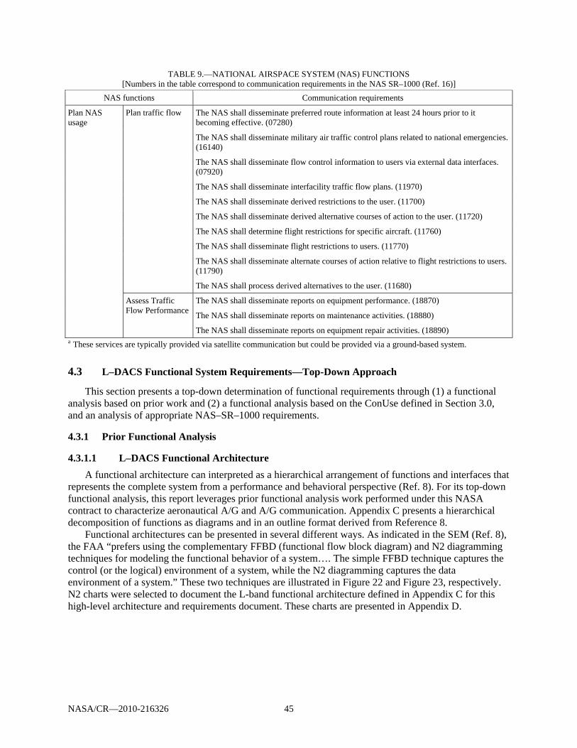
NASA/CR—2010-216326 45
TABLE 9.—NATIONAL AIRSPACE SYSTEM (NAS) FUNCTIONS [Numbers in the table correspond to communication requirements in the NAS SR–1000 (Ref. 16)]
NAS functions Communication requirements
Plan NAS usage
Plan traffic flow The NAS shall disseminate preferred route information at least 24 hours prior to it becoming effective. (07280)
The NAS shall disseminate military air traffic control plans related to national emergencies. (16140)
The NAS shall disseminate flow control information to users via external data interfaces. (07920)
The NAS shall disseminate interfacility traffic flow plans. (11970)
The NAS shall disseminate derived restrictions to the user. (11700)
The NAS shall disseminate derived alternative courses of action to the user. (11720)
The NAS shall determine flight restrictions for specific aircraft. (11760)
The NAS shall disseminate flight restrictions to users. (11770)
The NAS shall disseminate alternate courses of action relative to flight restrictions to users. (11790)
The NAS shall process derived alternatives to the user. (11680)
Assess Traffic Flow Performance
The NAS shall disseminate reports on equipment performance. (18870)
The NAS shall disseminate reports on maintenance activities. (18880)
The NAS shall disseminate reports on equipment repair activities. (18890) a These services are typically provided via satellite communication but could be provided via a ground-based system.
4.3 L–DACS Functional System Requirements—Top-Down Approach
This section presents a top-down determination of functional requirements through (1) a functional analysis based on prior work and (2) a functional analysis based on the ConUse defined in Section 3.0, and an analysis of appropriate NAS–SR–1000 requirements.
4.3.1 Prior Functional Analysis
4.3.1.1 L–DACS Functional Architecture
A functional architecture can interpreted as a hierarchical arrangement of functions and interfaces that represents the complete system from a performance and behavioral perspective (Ref. 8). For its top-down functional analysis, this report leverages prior functional analysis work performed under this NASA contract to characterize aeronautical A/G and A/G communication. Appendix C presents a hierarchical decomposition of functions as diagrams and in an outline format derived from Reference 8.
Functional architectures can be presented in several different ways. As indicated in the SEM (Ref. 8), the FAA “prefers using the complementary FFBD (functional flow block diagram) and N2 diagramming techniques for modeling the functional behavior of a system…. The simple FFBD technique captures the control (or the logical) environment of a system, while the N2 diagramming captures the data environment of a system.” These two techniques are illustrated in Figure 22 and Figure 23, respectively. N2 charts were selected to document the L-band functional architecture defined in Appendix C for this high-level architecture and requirements document. These charts are presented in Appendix D.
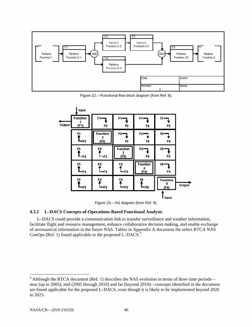
NASA/CR—2010-216326 46
Figure 22.—Functional flow block diagram (from Ref. 8).
Figure 23.—N2 diagram (from Ref. 8).
4.3.2 L–DACS Concepts-of-Operations-Based Functional Analysis
L–DACS could provide a communication link to transfer surveillance and weather information, facilitate flight and resource management, enhance collaborative decision making, and enable exchange of aeronautical information in the future NAS. Tables in Appendix A document the select RTCA NAS ConOps (Ref. 1) found applicable to the proposed L–DACS.9
9 Although the RTCA document (Ref. 1) describes the NAS evolution in terms of three time periods—near (up to 2005), mid (2005 through 2010) and far (beyond 2010)—concepts identified in the document are found applicable for the proposed L–DACS, even though it is likely to be implemented beyond 2020 to 2025.

NASA/CR—2010-216326 47
L–DACS should enable a reliable and consistent data exchange by providing the following functionality:
Enable G/A and A/G communication for fixed-to-mobile as well as mobile-to-mobile users Enable A/A communication Support addressed communication for delivery of information to individual and multiple users Support broadcast communication for delivery of information to multiple users Support delivery of real-time information in a timely manner Enable demand, periodic, and event communication Accommodate a wide range of data types (e.g., surveillance reports, weather raw data and
products, flight profiles) to support common situational awareness Support multiple QoS, priority, and preemption Support authentication of users and controlled access to NAS information (security) Provide support of both FAA and non-FAA ground and airborne users Avoid single points of failure Provide a scalable solution Provide standards-based solution Table 10 presents system requirements associated with the above functionality.
TABLE 10.—MAPPING OF L–DACS SYSTEM FUNCTIONS TO SYSTEM REQUIREMENTS
System functions System requirementsa
Enable ground-to-air (G/A) and air-to-ground (A/G) communication for fixed-to- mobile as well as mobile- to-mobile users
The system shall enable G/A communication for fixed-to-mobile users.
The system shall enable G/A communication for mobile-to-mobile users.
The system shall enable A/G communication for fixed-to-mobile users.
The system shall enable A/G communication for mobile-to-mobile users.
Enable air-to-air (A/A) communication The system shall enable A/A communication
Support addressed communication for delivery of information to individual and multiple users
The system shall support addressed communication for delivery of information to individual users
The system shall support addressed communication for delivery of information to multiple users
Support broadcast communication for delivery of information to multiple users
The system shall support broadcast communication for delivery of information to multiple users
Support delivery of real-time information in a timely manner
The system shall support delivery of real-time information in a timely manner
Enable demand, periodic, and event communication The system shall enable demand communication The system shall enable periodic communication The system shall enable event communication
Accommodate a wide range of data types (e.g., surveillance reports, weather raw data and products, flight profiles, etc.) to support common situational awareness
The system shall accommodate a wide range of data types (e.g., surveillance reports, weather raw data and products, flight profiles, etc.) to support common situational awareness
Support multiple quality of service (QoS) provisions The system shall support multiple QoS offerings, such as priority and preemption capabilities, and so on
Support authentication of users and controlled access to National Airspace System (NAS) information (security)
The system shall support authentication of users (security)
The system shall support controlled access to NAS information (security)

NASA/CR—2010-216326 48
TABLE 10.—MAPPING OF L–DACS SYSTEM FUNCTIONS TO SYSTEM REQUIREMENTS
System functions System requirementsa
Provide support of both Federal Aviation Administration (FAA) and non-FAA ground and airborne usersb
The system shall provide support of FAA ground users
The system shall provide support of FAA airborne users
The system shall provide support of non-FAA ground users
The system shall provide support of non-FAA airborne users
Avoid single points of failure The system shall avoid single points of failure
Provide a scalable solution The system shall provide a scalable solution
Provide standards-based solution The system shall provide standards-based solution aAll the requirements presented in the document are documented as “system shall” not “system must.” The verbiage is consistent with that used in the NAS SR–1000 as opposed to some of the newer requirements documents, for example Data Comm FPR. bTo support increasing collaboration among NAS users, the proposed system shall accommodate a wide range of NAS users by accepting NAS data from NAS data sources, both internal and external to the FAA. Users may include aircraft, airline operation centers, service providers, FAA users, and other government agencies.
The identified NAS ConOps can then be traced to the desired functionality of the proposed network. Table 11 maps capabilities identified in the ConUse activities and described in the preceding sections to specific functions necessary to enable those concepts. These functions are grouped into appropriate functional hierarchies and functional requirements are derived. This encompasses a top-down approach to the development of functional requirements. Mapping the proposed services to the desired system capabilities and functional architectures presents combined functional requirements from the top-down and bottom-up approaches.
TABLE 11.—MAPPING L–DACS FUNCTIONALITY TO NATIONAL AIRSPACE SYSTEM (NAS) CONCEPTS OF OPERATIONS (ConOps)
[Acronyms are defined in Appendix A.] Desired L–DACS capabilities 4.3.3 NAS ConOps referencesa Functional
hierarchy reference
Communications operating concept and requirements (COCR) air traffic
services (ATS)
Enable ground-to-air (G/A) and air-to-ground (A/G) communication for fixed to mobile as well as mobile to mobile users.
S–1; S–3; S–4; W–2; W–3; W–5; W–9; W–10; W–11; W–12; W–14; W–15; W–16; W–17; W–19; W–20; W–22; W–27; FM–3; FM–6; FM–9; FM–11; FM–13; FM–17; FM–21; FM–22; FM 24; FM–32; FM–41, FM–42; A–5; A–14; A–23; A–26; A–28; A–29; A–30; A–33; A–34
L.1.1.1.1 L.1.1.1.2 L.1.1.2.1 L.1.1.2.2
D–ORIS D–OTIS D–RVR DYNAV FLYPCY SAP WAKE PPD URCO
Enable air-to-air (A/A) communication S–7; W–26
L.1.1.3.1 AIRSEP
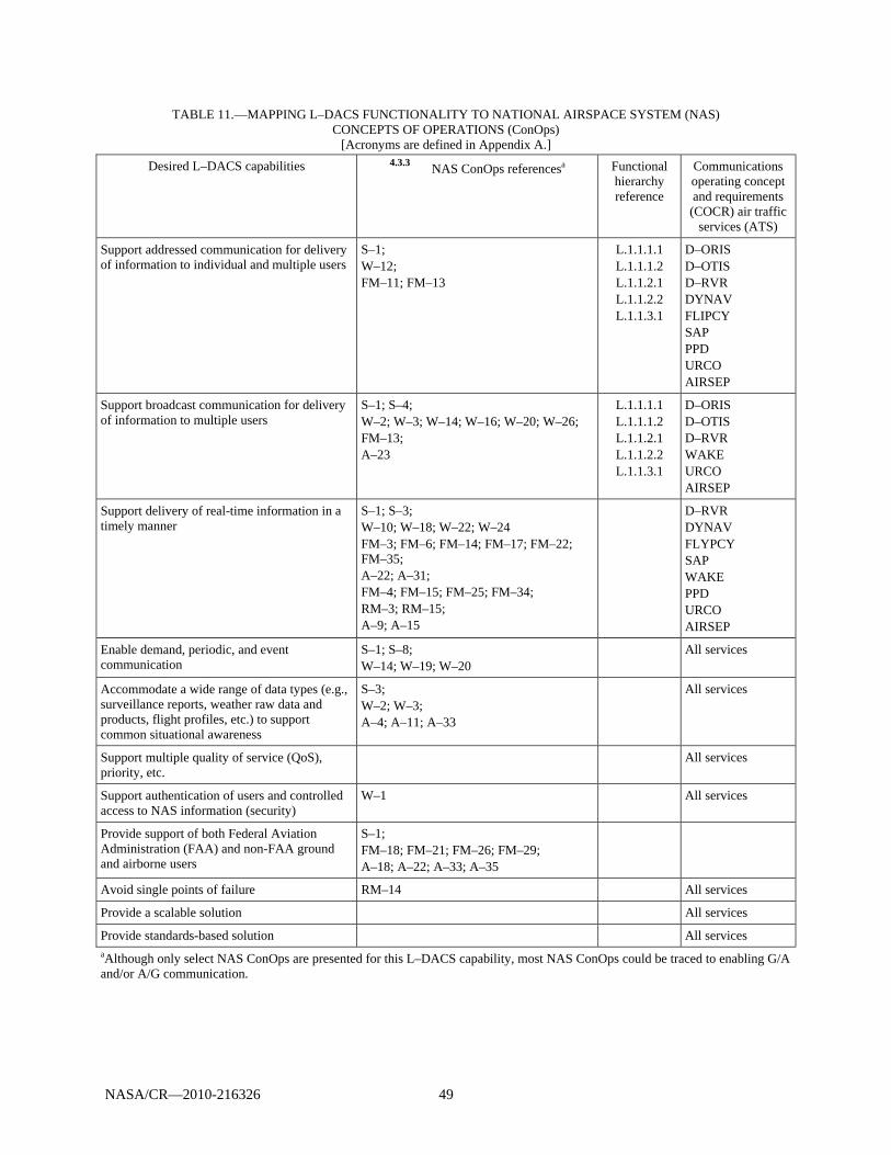
NASA/CR—2010-216326 49
TABLE 11.—MAPPING L–DACS FUNCTIONALITY TO NATIONAL AIRSPACE SYSTEM (NAS) CONCEPTS OF OPERATIONS (ConOps)
[Acronyms are defined in Appendix A.] Desired L–DACS capabilities 4.3.3 NAS ConOps referencesa Functional
hierarchy reference
Communications operating concept and requirements (COCR) air traffic
services (ATS)
Support addressed communication for delivery of information to individual and multiple users
S–1; W–12; FM–11; FM–13
L.1.1.1.1 L.1.1.1.2 L.1.1.2.1 L.1.1.2.2 L.1.1.3.1
D–ORIS D–OTIS D–RVR DYNAV FLIPCY SAP PPD URCO AIRSEP
Support broadcast communication for delivery of information to multiple users
S–1; S–4; W–2; W–3; W–14; W–16; W–20; W–26; FM–13; A–23
L.1.1.1.1 L.1.1.1.2 L.1.1.2.1 L.1.1.2.2 L.1.1.3.1
D–ORIS D–OTIS D–RVR WAKE URCO AIRSEP
Support delivery of real-time information in a timely manner
S–1; S–3; W–10; W–18; W–22; W–24 FM–3; FM–6; FM–14; FM–17; FM–22; FM–35; A–22; A–31; FM–4; FM–15; FM–25; FM–34; RM–3; RM–15; A–9; A–15
D–RVR DYNAV FLYPCY SAP WAKE PPD URCO AIRSEP
Enable demand, periodic, and event communication
S–1; S–8; W–14; W–19; W–20
All services
Accommodate a wide range of data types (e.g., surveillance reports, weather raw data and products, flight profiles, etc.) to support common situational awareness
S–3; W–2; W–3; A–4; A–11; A–33
All services
Support multiple quality of service (QoS), priority, etc.
All services
Support authentication of users and controlled access to NAS information (security)
W–1 All services
Provide support of both Federal Aviation Administration (FAA) and non-FAA ground and airborne users
S–1; FM–18; FM–21; FM–26; FM–29; A–18; A–22; A–33; A–35
Avoid single points of failure RM–14 All services
Provide a scalable solution All services
Provide standards-based solution All services aAlthough only select NAS ConOps are presented for this L–DACS capability, most NAS ConOps could be traced to enabling G/A and/or A/G communication.
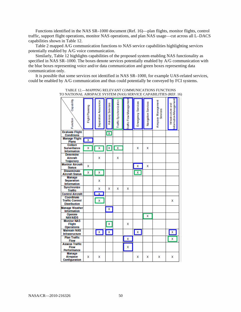
NASA/CR—2010-216326 50
Functions identified in the NAS SR–1000 document (Ref. 16)—plan flights, monitor flights, control traffic, support flight operations, monitor NAS operations, and plan NAS usage—cut across all L–DACS capabilities shown in Table 12.
Table 2 mapped A/G communication functions to NAS service capabilities highlighting services potentially enabled by A/G voice communication.
Similarly, Table 12 highlights capabilities of the proposed system enabling NAS functionality as specified in NAS SR–1000. The boxes denote services potentially enabled by A/G communication with the blue boxes representing voice and/or data communication and green boxes representing data communication only.
It is possible that some services not identified in NAS SR–1000, for example UAS-related services, could be enabled by A/G communication and thus could potentially be conveyed by FCI systems.
TABLE 12.—MAPPING RELEVANT COMMUNICATIONS FUNCTIONS TO NATIONAL AIRSPACE SYSTEM (NAS) SERVICE CAPABILITIES (REF. 16)
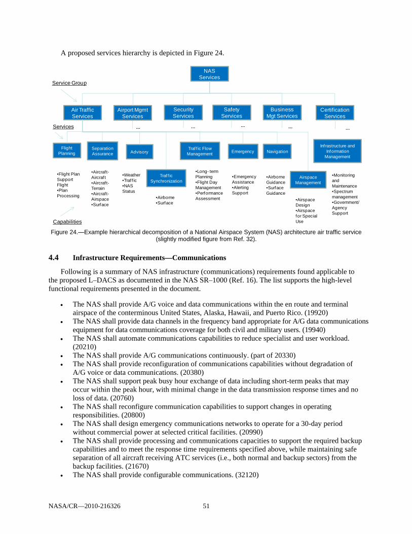
NASA/CR—2010-216326 51
A proposed services hierarchy is depicted in Figure 24.
Figure 24.—Example hierarchical decomposition of a National Airspace System (NAS) architecture air traffic service
(slightly modified figure from Ref. 32).
4.4 Infrastructure Requirements—Communications
Following is a summary of NAS infrastructure (communications) requirements found applicable to the proposed L–DACS as documented in the NAS SR–1000 (Ref. 16). The list supports the high-level functional requirements presented in the document.
The NAS shall provide A/G voice and data communications within the en route and terminal airspace of the conterminous United States, Alaska, Hawaii, and Puerto Rico. (19920)
The NAS shall provide data channels in the frequency band appropriate for A/G data communications equipment for data communications coverage for both civil and military users. (19940)
The NAS shall automate communications capabilities to reduce specialist and user workload. (20210)
The NAS shall provide A/G communications continuously. (part of 20330) The NAS shall provide reconfiguration of communications capabilities without degradation of
A/G voice or data communications. (20380) The NAS shall support peak busy hour exchange of data including short-term peaks that may
occur within the peak hour, with minimal change in the data transmission response times and no loss of data. (20760)
The NAS shall reconfigure communication capabilities to support changes in operating responsibilities. (20800)
The NAS shall design emergency communications networks to operate for a 30-day period without commercial power at selected critical facilities. (20990)
The NAS shall provide processing and communications capacities to support the required backup capabilities and to meet the response time requirements specified above, while maintaining safe separation of all aircraft receiving ATC services (i.e., both normal and backup sectors) from the backup facilities. (21670)
The NAS shall provide configurable communications. (32120)
NAS Services
Air Traffic Services
Airport Mgmt Services
Security Services
Safety Services
Business Mgt Services
Certification Services
Flight Planning
Separation Assurance Advisory
Traf f ic Synchronization
Traf f ic Flow Management Emergency Navigation
Airspace Management
Inf rastructure and Information
Management
•Flight Plan Support Flight •Plan Processing
•Aircraf t-Aircraf t•Aircraf t-Terrain•Aircraf t-Airspace•Surface
•Weather•Traf f ic•NAS Status
…
•Airborne•Surface
•Long- term Planning•Flight Day Management•Performance Assessment
•Emergency Assistance•Alerting Support
… …
•Airborne Guidance•Surface Guidance
… …
•Airspace Design•Airspace for Special Use
•Monitoring and Maintenance•Spectrum management•Government/ Agency Support
Service Group
Services
Capabilities
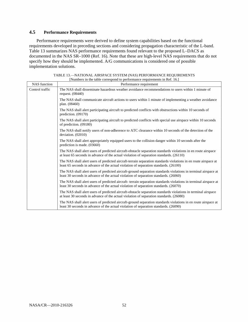
NASA/CR—2010-216326 52
4.5 Performance Requirements
Performance requirements were derived to define system capabilities based on the functional requirements developed in preceding sections and considering propagation characteristic of the L-band. Table 13 summarizes NAS performance requirements found relevant to the proposed L–DACS as documented in the NAS SR–1000 (Ref. 16). Note that these are high-level NAS requirements that do not specify how they should be implemented. A/G communications is considered one of possible implementation solutions.
TABLE 13.—NATIONAL AIRSPACE SYSTEM (NAS) PERFORMANCE REQUIREMENTS
[Numbers in the table correspond to performance requirements in Ref. 16.] NAS function Performance requirement
Control traffic The NAS shall disseminate hazardous weather avoidance recommendations to users within 1 minute of request. (08440)
The NAS shall communicate aircraft actions to users within 1 minute of implementing a weather avoidance plan. (08460)
The NAS shall alert participating aircraft to predicted conflicts with obstructions within 10 seconds of prediction. (09170)
The NAS shall alert participating aircraft to predicted conflicts with special use airspace within 10 seconds of prediction. (09180)
The NAS shall notify users of non-adherence to ATC clearance within 10 seconds of the detection of the deviation. (02010)
The NAS shall alert appropriately equipped users to the collision danger within 10 seconds after the prediction is made. (03660)
The NAS shall alert users of predicted aircraft-obstacle separation standards violations in en route airspace at least 65 seconds in advance of the actual violation of separation standards. (26110)
The NAS shall alert users of predicted aircraft-terrain separation standards violations in en route airspace at least 65 seconds in advance of the actual violation of separation standards. (26100)
The NAS shall alert users of predicted aircraft-ground separation standards violations in terminal airspace at least 30 seconds in advance of the actual violation of separation standards. (26060)
The NAS shall alert users of predicted aircraft- terrain separation standards violations in terminal airspace at least 30 seconds in advance of the actual violation of separation standards. (26070)
The NAS shall alert users of predicted aircraft-obstacle separation standards violations in terminal airspace at least 30 seconds in advance of the actual violation of separation standards. (26080)
The NAS shall alert users of predicted aircraft-ground separation standards violations in en route airspace at least 30 seconds in advance of the actual violation of separation standards. (26090)
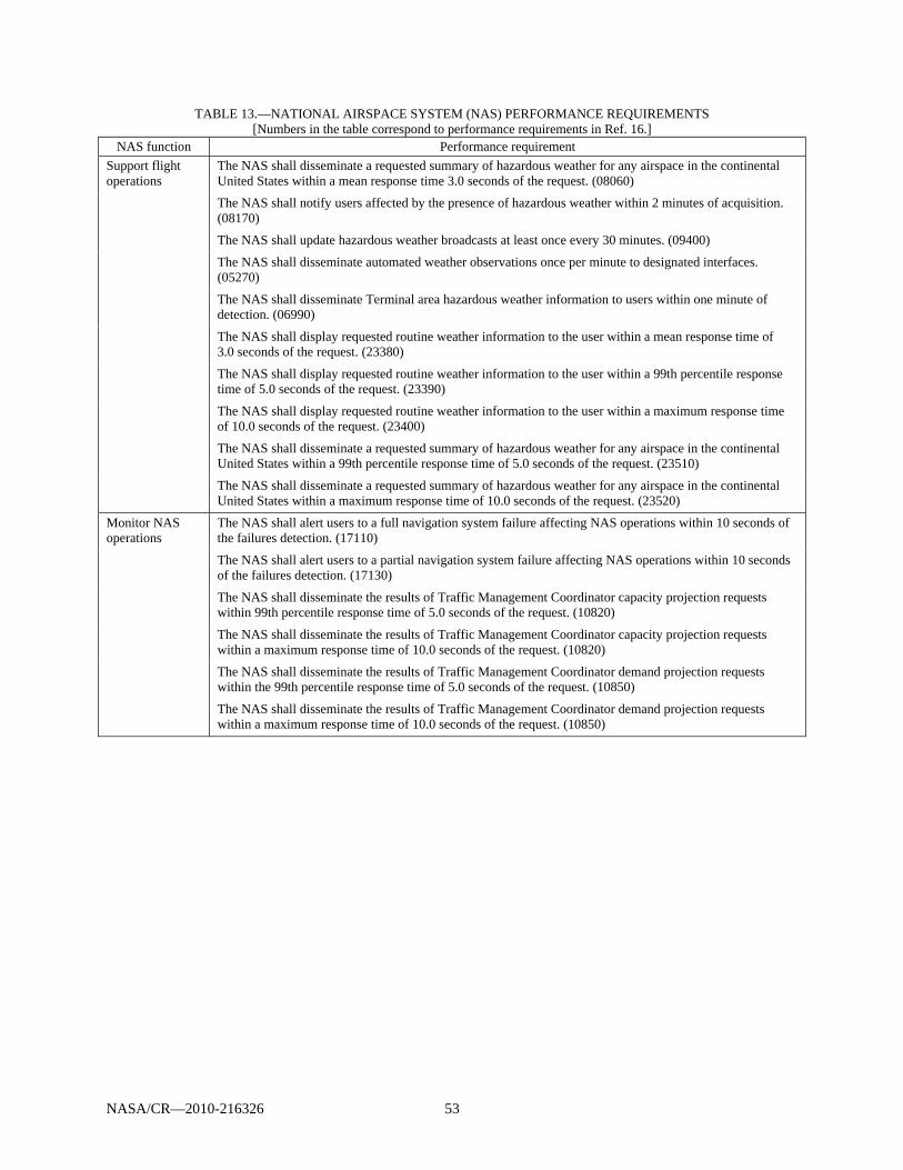
NASA/CR—2010-216326 53
TABLE 13.—NATIONAL AIRSPACE SYSTEM (NAS) PERFORMANCE REQUIREMENTS [Numbers in the table correspond to performance requirements in Ref. 16.]
NAS function Performance requirement Support flight operations
The NAS shall disseminate a requested summary of hazardous weather for any airspace in the continental United States within a mean response time 3.0 seconds of the request. (08060)
The NAS shall notify users affected by the presence of hazardous weather within 2 minutes of acquisition. (08170)
The NAS shall update hazardous weather broadcasts at least once every 30 minutes. (09400)
The NAS shall disseminate automated weather observations once per minute to designated interfaces. (05270)
The NAS shall disseminate Terminal area hazardous weather information to users within one minute of detection. (06990)
The NAS shall display requested routine weather information to the user within a mean response time of 3.0 seconds of the request. (23380)
The NAS shall display requested routine weather information to the user within a 99th percentile response time of 5.0 seconds of the request. (23390)
The NAS shall display requested routine weather information to the user within a maximum response time of 10.0 seconds of the request. (23400)
The NAS shall disseminate a requested summary of hazardous weather for any airspace in the continental United States within a 99th percentile response time of 5.0 seconds of the request. (23510)
The NAS shall disseminate a requested summary of hazardous weather for any airspace in the continental United States within a maximum response time of 10.0 seconds of the request. (23520)
Monitor NAS operations
The NAS shall alert users to a full navigation system failure affecting NAS operations within 10 seconds of the failures detection. (17110)
The NAS shall alert users to a partial navigation system failure affecting NAS operations within 10 seconds of the failures detection. (17130)
The NAS shall disseminate the results of Traffic Management Coordinator capacity projection requests within 99th percentile response time of 5.0 seconds of the request. (10820)
The NAS shall disseminate the results of Traffic Management Coordinator capacity projection requests within a maximum response time of 10.0 seconds of the request. (10820)
The NAS shall disseminate the results of Traffic Management Coordinator demand projection requests within the 99th percentile response time of 5.0 seconds of the request. (10850)
The NAS shall disseminate the results of Traffic Management Coordinator demand projection requests within a maximum response time of 10.0 seconds of the request. (10850)
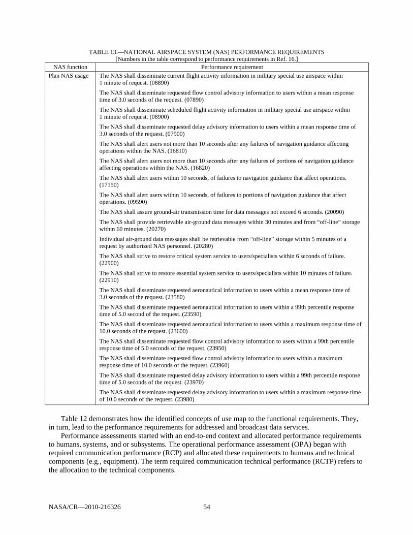
NASA/CR—2010-216326 54
TABLE 13.—NATIONAL AIRSPACE SYSTEM (NAS) PERFORMANCE REQUIREMENTS [Numbers in the table correspond to performance requirements in Ref. 16.]
NAS function Performance requirement Plan NAS usage The NAS shall disseminate current flight activity information in military special use airspace within
1 minute of request. (08890)
The NAS shall disseminate requested flow control advisory information to users within a mean response time of 3.0 seconds of the request. (07890)
The NAS shall disseminate scheduled flight activity information in military special use airspace within 1 minute of request. (08900)
The NAS shall disseminate requested delay advisory information to users within a mean response time of 3.0 seconds of the request. (07900)
The NAS shall alert users not more than 10 seconds after any failures of navigation guidance affecting operations within the NAS. (16810)
The NAS shall alert users not more than 10 seconds after any failures of portions of navigation guidance affecting operations within the NAS. (16820)
The NAS shall alert users within 10 seconds, of failures to navigation guidance that affect operations. (17150)
The NAS shall alert users within 10 seconds, of failures to portions of navigation guidance that affect operations. (09590)
The NAS shall assure ground-air transmission time for data messages not exceed 6 seconds. (20090)
The NAS shall provide retrievable air-ground data messages within 30 minutes and from “off-line” storage within 60 minutes. (20270)
Individual air-ground data messages shall be retrievable from “off-line” storage within 5 minutes of a request by authorized NAS personnel. (20280)
The NAS shall strive to restore critical system service to users/specialists within 6 seconds of failure. (22900)
The NAS shall strive to restore essential system service to users/specialists within 10 minutes of failure. (22910)
The NAS shall disseminate requested aeronautical information to users within a mean response time of 3.0 seconds of the request. (23580)
The NAS shall disseminate requested aeronautical information to users within a 99th percentile response time of 5.0 second of the request. (23590)
The NAS shall disseminate requested aeronautical information to users within a maximum response time of 10.0 seconds of the request. (23600)
The NAS shall disseminate requested flow control advisory information to users within a 99th percentile response time of 5.0 seconds of the request. (23950)
The NAS shall disseminate requested flow control advisory information to users within a maximum response time of 10.0 seconds of the request. (23960)
The NAS shall disseminate requested delay advisory information to users within a 99th percentile response time of 5.0 seconds of the request. (23970)
The NAS shall disseminate requested delay advisory information to users within a maximum response time of 10.0 seconds of the request. (23980)
Table 12 demonstrates how the identified concepts of use map to the functional requirements. They,
in turn, lead to the performance requirements for addressed and broadcast data services. Performance assessments started with an end-to-end context and allocated performance requirements
to humans, systems, and or subsystems. The operational performance assessment (OPA) began with required communication performance (RCP) and allocated these requirements to humans and technical components (e.g., equipment). The term required communication technical performance (RCTP) refers to the allocation to the technical components.
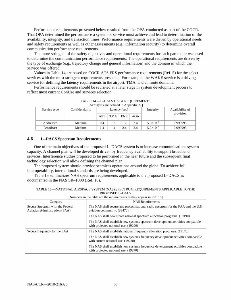
NASA/CR—2010-216326 55
Performance requirements presented below resulted from the OPA conducted as part of the COCR. That OPA determined the performance a system or service must achieve and lead to determination of the availability, integrity, and transaction times. Performance requirements were driven by operational needs and safety requirements as well as other assessments (e.g., information security) to determine overall communication performance requirements.
The more stringent of the safety objectives and operational requirements for each parameter was used to determine the communication performance requirements. The operational requirements are driven by the type of exchange (e.g., trajectory change and general information) and the domain in which the service was offered.
Values in Table 14 are based on COCR ATS FRS performance requirements (Ref. 5) for the select services with the most stringent requirements presented. For example, the WAKE service is a driving service for defining the latency requirements in the airport, TMA, and en route domains.
Performance requirements should be revisited at a later stage in system development process to reflect most current ConUse and services selection.
TABLE 14.—L–DACS DATA REQUIREMENTS [Acronyms are defined in Appendix A.]
Service type Confidentiality Latency (sec) Integrity Availability of provision
APT TMA ENR AOA
Addressed Medium 0.4 1.2 1.2 2.4 5.0×10⁻⁸ 0.999995 Broadcast Medium 1.4 1.4 2.4 2.4 5.0×10⁻⁸ 0.999995
4.6 L–DACS Spectrum Requirements
One of the main objectives of the proposed L–DACS system is to increase communications system capacity. A channel plan will be developed driven by frequency availability to support broadband services. Interference studies proposed to be performed in the near future and the subsequent final technology selection will allow defining the channel plan.
The proposed system should provide seamless operations around the globe. To achieve full interoperability, international standards are being developed.
Table 15 summarizes NAS spectrum requirements applicable to the proposed L–DACS as documented in the NAS SR–1000 (Ref. 16).
TABLE 15.—NATIONAL AIRSPACE SYSTEM (NAS) SPECTRUM REQUIREMENTS APPLICABLE TO THE
PROPOSED L–DACS [Numbers in the table are the requirements as they appear in Ref. 16]
Category NAS Requirements Secure Spectrum with the Federal Aviation Administration (FAA)
The NAS shall secure and protect national radio spectrum for the FAA and the U.S. aviation community. (32470)
The NAS shall coordinate national spectrum allocation programs. (19190)
The NAS shall establish new systems spectrum development activities compatible with projected national use. (19290)
Secure frequency for the FAA The NAS shall establish national frequency allocation programs. (19170)
The NAS shall establish new systems frequency development activities compatible with current national use. (19230)
The NAS shall establish new systems frequency development activities compatible with projected national use. (19270)
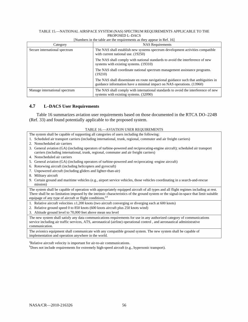
NASA/CR—2010-216326 56
TABLE 15.—NATIONAL AIRSPACE SYSTEM (NAS) SPECTRUM REQUIREMENTS APPLICABLE TO THE PROPOSED L–DACS
[Numbers in the table are the requirements as they appear in Ref. 16] Category NAS Requirements
Secure international spectrum The NAS shall establish new systems spectrum development activities compatible with current national use. (19250) The NAS shall comply with national standards to avoid the interference of new systems with existing systems. (19310) The NAS shall coordinate national spectrum management assistance programs. (19210) The NAS shall disseminate en route navigational guidance such that ambiguities in guidance information have a minimal impact on NAS operations. (13960)
Manage international spectrum The NAS shall comply with international standards to avoid the interference of new systems with existing systems. (32090)
4.7 L–DACS User Requirements
Table 16 summarizes aviation user requirements based on those documented in the RTCA DO–224B (Ref. 33) and found potentially applicable to the proposed system.
TABLE 16.—AVIATION USER REQUIREMENTS
The system shall be capable of supporting all categories of users including the following: 1. Scheduled air transport carriers (including international, trunk, regional, commuter and air freight carriers) 2. Nonscheduled air carriers 3. General aviation (GA) (including operators of turbine-powered and reciprocating-engine aircraft); scheduled air transport
carriers (including international, trunk, regional, commuter and air freight carriers) 4. Nonscheduled air carriers 5. General aviation (GA) (including operators of turbine-powered and reciprocating -engine aircraft) 6. Rotorwing aircraft (including helicopters and gyrocraft) 7. Unpowered aircraft (including gliders and lighter-than-air) 8. Military aircraft 9. Certain ground and maritime vehicles (e.g., airport service vehicles, those vehicles coordinating in a search-and-rescue
mission) The system shall be capable of operation with appropriately equipped aircraft of all types and all flight regimes including at rest. There shall be no limitation imposed by the intrinsic characteristics of the ground system or the signal-in-space that limit suitable equipage of any type of aircraft or flight conditions,a,b 1. Relative aircraft velocities ±1,200 knots (two aircraft converging or diverging each at 600 knots) 2. Relative ground speed 0 to 850 knots (600 knots aircraft plus 250 knots wind) 3. Altitude ground level to 70,000 feet above mean sea level The new system shall satisfy any data communications requirements for use in any authorized category of communications service including air traffic services, ATS, aeronautical (airline) operational control , and aeronautical administrative communication. The avionics equipment shall communicate with any compatible ground system. The new system shall be capable of implementation and operation anywhere in the world. aRelative aircraft velocity is important for air-to-air communications. bDoes not include requirements for extremely high-speed aircraft (e.g., hypersonic transport).
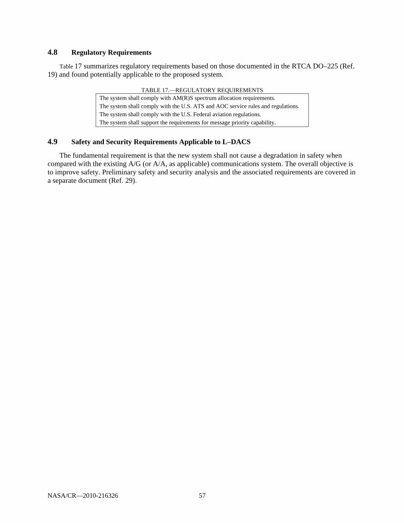
NASA/CR—2010-216326 57
4.8 Regulatory Requirements
Table 17 summarizes regulatory requirements based on those documented in the RTCA DO–225 (Ref. 19) and found potentially applicable to the proposed system.
TABLE 17.—REGULATORY REQUIREMENTS
The system shall comply with AM(R)S spectrum allocation requirements. The system shall comply with the U.S. ATS and AOC service rules and regulations. The system shall comply with the U.S. Federal aviation regulations. The system shall support the requirements for message priority capability.
4.9 Safety and Security Requirements Applicable to L–DACS
The fundamental requirement is that the new system shall not cause a degradation in safety when compared with the existing A/G (or A/A, as applicable) communications system. The overall objective is to improve safety. Preliminary safety and security analysis and the associated requirements are covered in a separate document (Ref. 29).
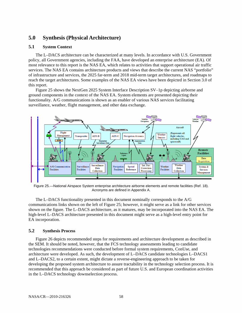
NASA/CR—2010-216326 58
5.0 Synthesis (Physical Architecture)
5.1 System Context
The L–DACS architecture can be characterized at many levels. In accordance with U.S. Government policy, all Government agencies, including the FAA, have developed an enterprise architecture (EA). Of most relevance to this report is the NAS EA, which relates to activities that support operational air traffic services. The NAS EA contains architecture products and views that describe the current NAS “portfolio” of infrastructure and services, the 2025 far-term and 2018 mid-term target architectures, and roadmaps to reach the target architectures. Some examples of the NAS EA views have been depicted in Section 3.0 of this report.
Figure 25 shows the NextGen 2025 System Interface Description SV–1p depicting airborne and ground components in the context of the NAS EA. System elements are presented depicting their functionality. A/G communications is shown as an enabler of various NAS services facilitating surveillance, weather, flight management, and other data exchange.
Figure 25.—National Airspace System enterprise architecture airborne elements and remote facilities (Ref. 18).
Acronyms are defined in Appendix A.
The L–DACS functionality presented in this document nominally corresponds to the A/G communications links shown on the left of Figure 25; however, it might serve as a link for other services shown on the figure. The L–DACS architecture, as it matures, may be incorporated into the NAS EA. The high-level L–DACS architecture presented in this document might serve as a high-level entry point for EA incorporation.
5.2 Synthesis Process
Figure 26 depicts recommended steps for requirements and architecture development as described in the SEM. It should be noted, however, that the FCS technology assessments leading to candidate technologies recommendations were conducted before formal system requirements, ConUse, and architecture were developed. As such, the development of L–DACS candidate technologies L–DACS1 and L–DACS2, to a certain extent, might dictate a reverse-engineering approach to be taken for developing the proposed system architecture to assure tractability in the technology selection process. It is recommended that this approach be considered as part of future U.S. and European coordination activities in the L–DACS technology downselection process.
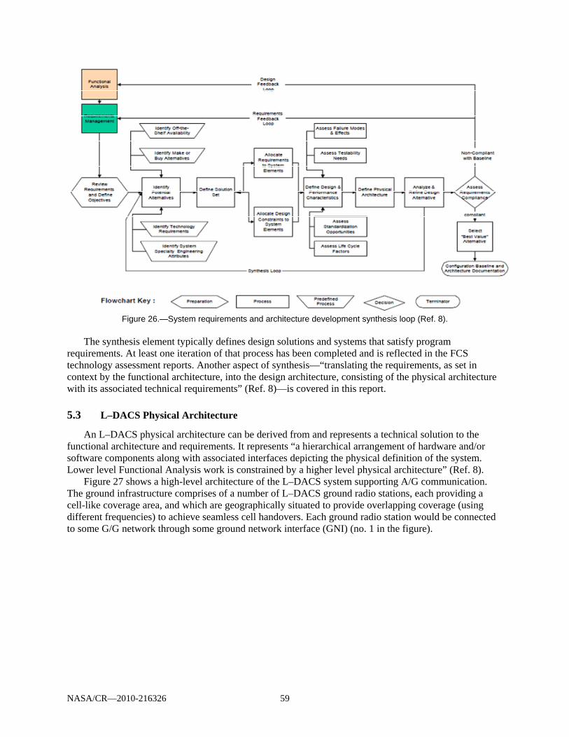
NASA/CR—2010-216326 59
Figure 26.—System requirements and architecture development synthesis loop (Ref. 8).
The synthesis element typically defines design solutions and systems that satisfy program
requirements. At least one iteration of that process has been completed and is reflected in the FCS technology assessment reports. Another aspect of synthesis—“translating the requirements, as set in context by the functional architecture, into the design architecture, consisting of the physical architecture with its associated technical requirements” (Ref. 8)—is covered in this report.
5.3 L–DACS Physical Architecture
An L–DACS physical architecture can be derived from and represents a technical solution to the functional architecture and requirements. It represents “a hierarchical arrangement of hardware and/or software components along with associated interfaces depicting the physical definition of the system. Lower level Functional Analysis work is constrained by a higher level physical architecture” (Ref. 8).
Figure 27 shows a high-level architecture of the L–DACS system supporting A/G communication. The ground infrastructure comprises of a number of L–DACS ground radio stations, each providing a cell-like coverage area, and which are geographically situated to provide overlapping coverage (using different frequencies) to achieve seamless cell handovers. Each ground radio station would be connected to some G/G network through some ground network interface (GNI) (no. 1 in the figure).
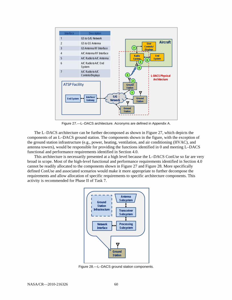
NASA/CR—2010-216326 60
Figure 27.—L–DACS architecture. Acronyms are defined in Appendix A.
The L–DACS architecture can be further decomposed as shown in Figure 27, which depicts the
components of an L–DACS ground station. The components shown in the figure, with the exception of the ground station infrastructure (e.g., power, heating, ventilation, and air conditioning (HVAC), and antenna towers), would be responsible for providing the functions identified in 0 and meeting L–DACS functional and performance requirements identified in Section 4.0.
This architecture is necessarily presented at a high level because the L–DACS ConUse so far are very broad in scope. Most of the high-level functional and performance requirements identified in Section 4.0 cannot be readily allocated to the components shown in Figure 27 and Figure 28. More specifically defined ConUse and associated scenarios would make it more appropriate to further decompose the requirements and allow allocation of specific requirements to specific architecture components. This activity is recommended for Phase II of Task 7.
Figure 28.—L–DACS ground station components.
Aircraft
ATSP Facility
End SystemInterface/Gateway
G/G Network
Ground Station
Radio System
End System
User Controls/Displays
2
3
4
5
7
Interface Description
1 GS to G/G Network
2 GS to GS Antenna
3 GS Antenna RF Interface
4 A/C Antenna RF Interface
5 A/C Radio to A/C Antenna
6 A/C Radio to A/C End System
7 A/C Radio to A/C Controls/Displays
6
1
L-DACS Physical Architecture
Ground Station
Ground Station
Ground Station
TransceiverSubsystem
ProcessingSubsystem
AntennaSubsystem
NetworkInterface
Ground Station
Infrastructure

NASA/CR—2010-216326 61
6.0 Unmanned Aircraft Systems (UAS)
6.1 Unmanned Aircraft System Operations
The RTCA Issue Paper SC203-CC01110 describes the characteristics of the current UAS control and communications (CC) data links. The main attributes of the current UAS would apply to the proposed system as well when services are provided over the L–DACS and as such are detailed below.
Most current UAS are equipped with line-of-site (LOS) control data links. UA with more
autonomy (e.g., automatic takeoff and landing) rely less on the LOS system for takeoff and landing, since the pilot is not “in-the-loop” (actively flying the aircraft) but “on-the-loop” (monitoring the flight of the aircraft with the capability to override preprogrammed maneuvers if needed). However, such systems will still require LOS control data links. The level of reliance on the LOS system is reflected in the level of control data link redundancy and low latency adopted by different UAS. Most pilot in-the-loop takeoff and landing UAS use dual redundant data links and have low pilot-control-input-to-pilot-observable-response latencies since the pilot is actively maneuvering the aircraft in real time. Conversely, pilot on-the-loop systems often only have single-thread LOS data links and higher latencies because the pilot is not in real-time control of the takeoff or landing maneuvers. Dual redundant LOS control data links offer the advantage of having two sets of data link equipment significantly improving the overall mean time between failures (MTBF) of the data link. The two links can also offer improved data link availability. For example, if one of the links is temporarily suffering degradation, due to interference or propagation-related effects, then the other link in a different frequency band could take over the delivery of telecommands and telemetry, since interference and propagation effects are not correlated for the two links. Both links could be provided over the L–DACS.
Some current UAS are equipped with BLOS UA control systems. Most are satellite-based, offering wide geographical coverage and allowing the aircraft to be controlled thousands of miles away from its takeoff and landing location. While most takeoff and landing activity is controlled using the LOS systems, at a manufacturer-specific altitude or range, the UAS is switched from LOS to BLOS control and is usually flown this way for the bulk of the distant flight activity. The pilot using the LOS system to control the aircraft does not necessarily have to be the same pilot controlling the aircraft using the BLOS system. A LOS system will again be used for landing, but not necessarily the same one that was used for takeoff. This allows the UA to make landings at distant locations and also allows for pilot relief. To enhance link availability when using satellite communications, current UAS that fly BLOS missions often utilize two or three different satellite communications systems, all operating in parallel. Typically, the flight computer on the aircraft and the computer in the control station simultaneously monitor all links and choose, on a real-time basis, the best link as appropriate. This link choice can also be manually controlled by the pilot. The proposed L–DACS will not offer BLOS communication; these links will remain satellite-based.
Not all current UA carry voice communication equipment. However, all UAS have the ability for their pilot to have voice communication with air traffic controllers and pilots of other aircraft.
10 This section is adopted from Ref. 34.

NASA/CR—2010-216326 62
Current UA that are equipped only for LOS flights often have their VHF voice transceivers located in their control stations. This is adequate when the control-station based VHF transceiver can maintain voice communication with the controlling ATC entity; however, for BLOS operation this is unacceptable. For present-day BLOS missions, the VHF voice communication equipment must be carried on the aircraft so the pilot can communicate with various ATC centers or pilots as the aircraft transits different regions. In current BLOS UAS the voice traffic is carried (along with the telecommands and telemetry) as part of the overall data link between the control station and the aircraft. Most of the VHF voice equipment currently used for both LOS and BLOS systems is standard equipment covered by current technical standard orders (TSOs). However, the method for monitoring the voice traffic between the pilot and the VHF equipment, when it is carried by the aircraft flying a BLOS mission, is not specifically covered by current regulations. It should be noted that while the proposed L–DACS could support voice communication, only data communication was planned over the L-band for manned aircraft.
As all mobile radio communication systems, those used on UA, are designed to achieve a specific level of performance and under certain conditions could become temporarily unavailable. Typically, given the statistical nature of the situation, the data links will return to full functionality. The amount of time a particular UA can operate without its data links is dependent on its design and level of autonomy, but after a certain amount of time without a data link all systems must declare that the link is lost. The vast majority of UA have built in procedures to accommodate lost link situations. Again, the level of autonomy plays a major part in what the UA does after losing its link, but in most cases the aircraft will fly a preplanned maneuver trying to reestablish any data link that might be available while making its way to a precoordinated location where it can be picked up again by the LOS system located at that facility. Transponder-equipped UA may set their transponders to squawk certain codes as part of their lost link procedure. Lost link procedures will need to be developed for the proposed L-band system.
Although the Department of Defense (DoD) uses a variety of frequencies for its UAS CC data links (operating in predominantly restricted airspace), no frequency bands are currently allocated specifically for unmanned aircraft use in the NAS. Current UAS Spectrum Usage includes a wide range of frequency bands for control of the UA. Systems operate on frequencies ranging from VHF (72 MHz) up to Ka-band (27 to 40 GHz). The factors driving the choice of frequency are related to limiting the size, weight and power of the airborne data link equipment—particularly antennas and power amplifiers—as well as data rates required. Many BLOS systems share the control link and the payload return link on one common carrier so the wide bandwidth needs of the payload return link may drive this choice more than the lower data-rate needs of the control link.
Spectrum provision for CC is essential for the safe operation of UA and their integration in the NAS. Appendix E discusses UAS spectrum requirements for the proposed L–DACS. Appendix F contains the details of the L–DACS applicability to UAS applications.
Various messages are carried on the CC links to deliver information exchanges that ensure safe, reliable, and effective UA flight operation. The functions of the data link can be related to the following types of information that are exchanged: – Telecommand messages: These messages are used for flight control and task execution and
usually have higher priority than other message types. They include aerodynamic control messages, power plant control messages, and messages associated with changing the status of

NASA/CR—2010-216326 63
the avionics (e.g., frequency of the VHF ATC radio) or aircraft (e.g., raise and lower the landing gear).
– Nonpayload telemetry data: Telemetry data is sent from the UA to the control station and can include a broad range of information. The first type of information relates to the flight characteristics of the UA. This data includes items such as position, flight trajectory, altimeter setting, altitude, heading, speed, route clearance, and arrival time. The pilot uses this data to maintain full awareness of the flight of the UA and to determine the changes needed to ensure safe flight. The second type of information relates to the health and status of UA. Health and status data provides critical information about the condition of the subsystems, sensors, and hardware of the UA. The pilot at the control station uses this information to maintain full awareness of the ability of the UA to function and to diagnose problems. The pilot can then handle potential or actual problems by taking preventive measures or corrective actions to ensure continued functioning and thus safe flight. The third type of information relates to situation awareness data. This type of data describes the operational environment of a UA. Examples of this data are weather conditions and terrain information.
– Navigation aids: Pilot-to-UA uplink that enables the pilot to control the settings of the UA’s navigation receivers, and the UA-to-pilot downlink that carries data from those receivers to the pilot’s display.
– ATC voice relay: Spectrum is required for relaying (via the UA) voice message traffic between air traffic controllers and the pilot.
– ATS data relay: A nationwide system providing ATS data services of various kinds is expected to be in place by the 2020s. It seems likely that the messages associated with those services will need to be relayed to and from the pilot via the UA.
– Target-track data: Essential sources of target-track data will include: The sense-and-avoid (S&A) system (whose architecture is still undefined) traffic information services, broadcast (TIS–B) Automatic dependent surveillance (ADS)–broadcast (ADS–B) ADS–rebroadcast (ADS–R) ADS–contract (ADS–C)
– Nonpayload video downlink data: This data erves to enhance the pilot’s situational awareness, especially during takeoff and landing.
The types of messages discussed above apply to the proposed L-band system. As noted earlier, voice communication is not currently considered for the manned aircraft applications and therefore was not the focus of prior FCSs.
The capacity of the CC links used on current UAS is proprietary to the link manufacturer. However, a survey of publicly available literature indicates that data rates ranging from 1200 bps to 200 kbps are successfully used today to control UA.
To date, UA operations have been limited to segregated airspace.11 Studies are being conducted to
determine the implications of operating UAS in nonsegregated airspace. Currently, UAS use in the NAS 11 As noted in the proposed changes to Annex 16 of 5B/296-E in Ref. 35, the following definitions of types of airspaces were adopted in this document: ATC separation assurance—Air traffic control is responsible for safe separation of all aircraft. This
comprises Classes A, B, and, if the UAS is operated in accordance with instrument flight rules (IFR), Class C.
Limited or no ATC separation assurance—Air traffic control is not responsible for safe separation of all airspace users. This comprises Classes D, E, F, and G.
Segregated—A defined volume of airspace reserved for exclusive use of a particular user.
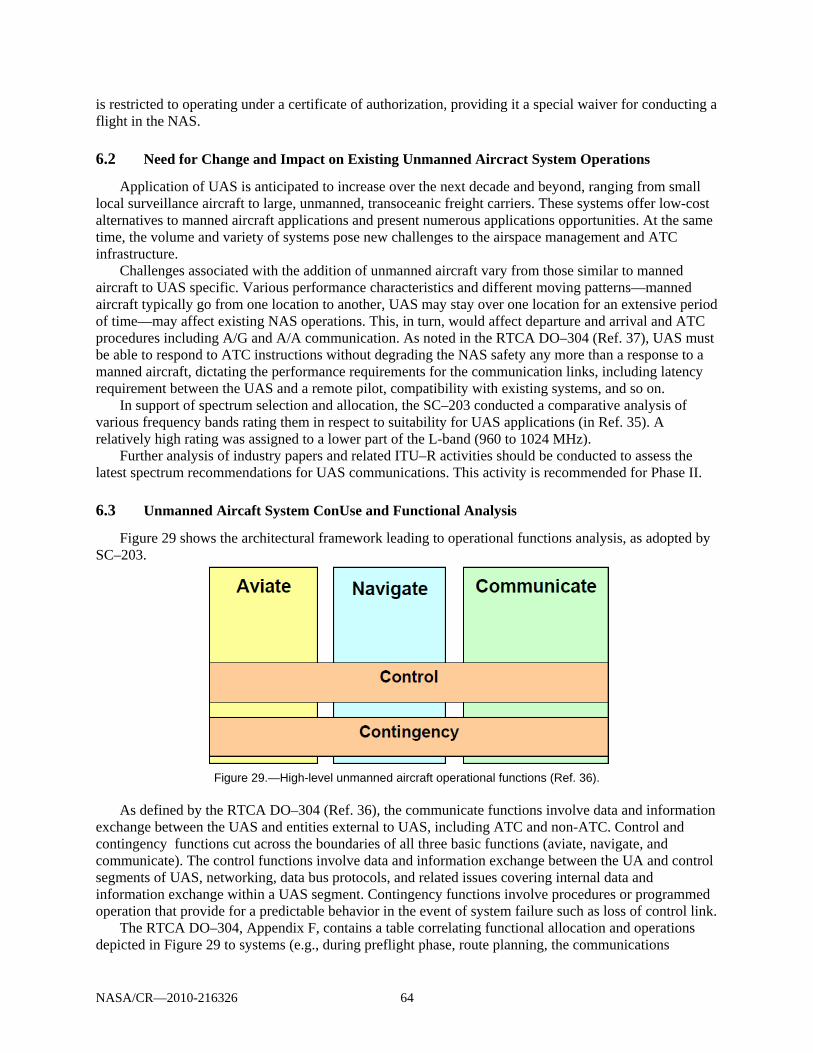
NASA/CR—2010-216326 64
is restricted to operating under a certificate of authorization, providing it a special waiver for conducting a flight in the NAS.
6.2 Need for Change and Impact on Existing Unmanned Aircract System Operations
Application of UAS is anticipated to increase over the next decade and beyond, ranging from small local surveillance aircraft to large, unmanned, transoceanic freight carriers. These systems offer low-cost alternatives to manned aircraft applications and present numerous applications opportunities. At the same time, the volume and variety of systems pose new challenges to the airspace management and ATC infrastructure.
Challenges associated with the addition of unmanned aircraft vary from those similar to manned aircraft to UAS specific. Various performance characteristics and different moving patterns—manned aircraft typically go from one location to another, UAS may stay over one location for an extensive period of time—may affect existing NAS operations. This, in turn, would affect departure and arrival and ATC procedures including A/G and A/A communication. As noted in the RTCA DO–304 (Ref. 37), UAS must be able to respond to ATC instructions without degrading the NAS safety any more than a response to a manned aircraft, dictating the performance requirements for the communication links, including latency requirement between the UAS and a remote pilot, compatibility with existing systems, and so on.
In support of spectrum selection and allocation, the SC–203 conducted a comparative analysis of various frequency bands rating them in respect to suitability for UAS applications (in Ref. 35). A relatively high rating was assigned to a lower part of the L-band (960 to 1024 MHz).
Further analysis of industry papers and related ITU–R activities should be conducted to assess the latest spectrum recommendations for UAS communications. This activity is recommended for Phase II.
6.3 Unmanned Aircaft System ConUse and Functional Analysis
Figure 29 shows the architectural framework leading to operational functions analysis, as adopted by SC–203.
Figure 29.—High-level unmanned aircraft operational functions (Ref. 36).
As defined by the RTCA DO–304 (Ref. 36), the communicate functions involve data and information
exchange between the UAS and entities external to UAS, including ATC and non-ATC. Control and contingency functions cut across the boundaries of all three basic functions (aviate, navigate, and communicate). The control functions involve data and information exchange between the UA and control segments of UAS, networking, data bus protocols, and related issues covering internal data and information exchange within a UAS segment. Contingency functions involve procedures or programmed operation that provide for a predictable behavior in the event of system failure such as loss of control link.
The RTCA DO–304, Appendix F, contains a table correlating functional allocation and operations depicted in Figure 29 to systems (e.g., during preflight phase, route planning, the communications
NASA/CR—2010-216326 65
function would be used to check spectrum availability and coverage for intended flight and for all alternate locations.) (Ref. 36).
In an ongoing effort to find an RF spectrum to support the CC12 links of UAS, UAS L-band is being considered as one of the possible systems to support UAS operations.
The proposed communication system should be designed and implemented to support a seamless integration of UAS operations into current ATC procedures while maintaining the required safety-of-flight levels.
For safe operations of UA under LOS and BLOS conditions, three functions of radio communications between UA and the control station (CS) are to be supported:13
ATC Relay The link (the downlink bringing the ATC information to the CS and the uplink allowing the remote pilot to communicate with ATC) between air traffic control and the CS via the UA will relay all ATC and A/A communications received and transmitted by the UA in nonsegregated airspace. For communicating with ATC, the UA will use the same equipment as a manned aircraft.
Command and Control The link will provide a two-way communication between the CS and the UA. The uplink will be used to send commands to the aircraft for navigation purposes. This is the command link that would probably necessitate low data rates. The downlink will be used to send the flight status of the UA to the remote pilot. It is anticipated that in some flight conditions or in specific airspaces it could be necessary to downlink video streams. Such a requirement could lead to data rates of several hundreds of kbps per UA.
In areas under the responsibility of the aeronautical authorities, it is expected that the Command and Control communications will have to be compliant with ICAO standards to be further specified on this function. Nevertheless, in the periods where the UA will follow a full autonomous flight, the up and down C2 [Command and Control] links could have very weak rates or be temporarily disrupted.14
Sense and Avoid This function is analogues with the piloting principle “see-and-avoid” used in all air space volumes where a pilot is responsible for ensuring separation from nearby aircraft, terrain and obstacles (e.g., weather). The system will support a two-way communication between the remote pilot and the UA. The uplink will allow the remote pilot to control the operation of this function according to the conditions of the flight likely requiring high bit rates. The downlink from the UAV to the CS or remote pilot will provide an indication that the function operates as desired. The necessity to send
12 The RTCA UAS Spectrum document limits the term “CC” to nonpayload links intended primarily to ensure the safety and regularity of UA flight. Payload applications such as the downlinking of surveillance data for non-safety purposes were excluded from the scope and not considered in estimating nationwide CC bandwidth requirements or evaluating candidate spectral bands. 13 Based on the research documented in the proposed changes to Ref. 35. 14 Based on the research documented in the proposed changes to Ref. 35.

NASA/CR—2010-216326 66
video streams must be considered avoiding duplication between command and control and sense-and-avoid video downlinks.
Similarly to the command and control considerations, it is expected that the “S&A data” [Sense and Avoid data] RF communication requirements will have to be compliant with future ICAO standards for the safe flight of the UA in areas under the responsibility of the aviation authorities.15
Thus, the three functions above can be further decomposed to show the following classes of LOS communications traffic to be supported by the proposed L-band system:
Pilot/UA control links, including telecommand and telemetry Pilot/UA NavAids data exchanges Relaying ATC voice messages to and from UA pilots Relaying ATS data messages to and from UA pilots UA-to-pilot downlinking of non-payload target track data UA-to-pilot downlinking of data from UA-borne weather radars UA-to-pilot downlinking of safety-related video data from UA to pilots UA-to-pilot downlinking of safety-related sense and avoid automated decisionmaking from UA
to pilots
The proposed system is to support a handover to transfer. A direct (LOS) RF communication to one dedicated CS16 to another (LOS) dedicated CS A direct (LOS) to an indirect (BLOS) RF communication link or vice versa
6.4 Unmanned Aircraft System Applications
Both commercial and Government applications could be provided over the L-band system. As defined by the ITU17 and illustrated in Figure 30, commercial applications would provide services that are sold by contractors in the course of carrying out normal business operations, while Governmental applications ensure public safety by addressing different emergencies and involve issues of public interest and include scientific matters.
15 Based on the research documented in the proposed changes to Ref. 35. 16 CS (Control Station)—One or more facilities or devices from which a UA is controlled remotely as defined in Proposed changes to Annex 16 of 5B/296-E in Ref. 35. 17 Based on the research documented in the proposed changes to Ref. 35.

NASA/CR—2010-216326 67
Figure 30.—Unmanned aircraft system applications (from proposed changes to Ref. 35).
6.5 Operational Scenarios
Example operational scenarios for each type of application are presented in Table 18. Additional scenarios and detail can be found in Reference 37.
TABLE 18.—UAS OPERATIONAL SCENARIOS [From proposed changes to Ref. 35.]
Mission type Scenario description
Movie making, sports games, popular events like concerts
Cargo planes with reduced manning (one-man-cockpit)
Inspections for industries (e.g., oil fields, oil platforms, oil pipelines, power line, rail line)
Provision of airborne relays for cell phones in the future
Commercial agricultural services like crop dusting
Earth science and geographic missions (e.g., mapping and surveying or aerial photography) and biological and environmental missions (e.g., animal monitoring, crop spraying, volcano monitoring, biomass surveys, livestock monitoring, or tree fertilization)
Coastline inspection, preventive border surveillance, drug control, anti-terrorism operations, strike events, search-and-rescue of people in distress, public interest missions (e.g.,remote weather monitoring, avalanche prediction and control, hurricane monitoring, forest fires prevention surveillance, insurance claims during disasters, and traffic surveillance)
Famine relief, medical support, aid delivery. Search and Rescue activities.
NASA/CR—2010-216326 68
6.6 Unmanned Aircraft System Requirements
6.6.1 Spectrum Requirements
Based on the research conducted by the ITU,18 a terrestrial LOS UAS system would require 34 MHz of spectrum.19 (Refer to Appendix E that presents Sections 5.0 and 6.0 (Spectrum requirements for UAS communications and Conclusions) of Ref. 35 for details.)
6.6.2 Safety and Latency Requirements
RTCA DO–304 (Ref. 36) notes the additional operational complexity associated with the UA. Unlike in manned aircraft operation, a pilot is remote from the aircraft with different people at potentially dispersed locations engaged in subsets of operation adding latency to aircraft operation.
Safe operations of future UAs in non-segregated airspace could need independent back-up communications.
A UA designed to fly in controlled airspace must be able to operate in both high and low density airspace. The air traffic control system would not necessarily be able to restrict it to low density airspace only. Hence
It is recommended that larger UAs be equipped with a terrestrial link capability wherever possible.
A UA may use a GEO satellite link in low density sectors and probably in high density sectors where the total number of UAs in that sector is low.
The impact of latency on UAS command and control systems is a prime factor when considering the safety of operations. Latency will be of the utmost importance when establishing a safety case for the operation of UAs, particularly in non-segregated airspace. Current air traffic management relies heavily on voice communications although information via data links is being progressively implemented. Hence new operational requirements for the future data link environment will also need to be developed (Ref. 35).
6.6.3 Other Requirements
The COCR Version 2.0 (Ref. 5) does not specifically address the requirements to support UAS command and control links (i.e., telecommand and telemetry). It does note that (Ref. 5):
[a]ll other communications services with UASs are considered to be the same as those with manned aircraft, i.e., UAS operation is transparent for the ATM system. In the future, in some parts of the world, the number of these vehicles may represent a large portion of an Air Traffic Service Unit’s (ATSU’s) traffic load. When providing ATS to a UAS, this may involve the relay of communication and execution instructions to and from a remote pilot; however, operational performance requirements between an ATSU and an UAS remain the same as those between an ATSU and any manned aircraft.
It should also be noted that UAS vary widely in their design and capabilities. This, in turn, would affect communication system requirements.
18 Assumptions and results presented in proposed changes to Annex 16 of 5B/296-E in Ref. 35. 19 The total UAS spectrum requirements are: 34 MHz for a terrestrial LOS system; 49 MHz for a spot-beam satellite system; 169 MHz for a regional-beam satellite system, which can be shared between several satellites, thereby reducing the overall spectrum requirement.
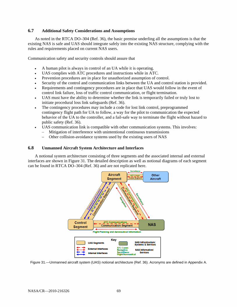
NASA/CR—2010-216326 69
6.7 Additional Safety Considerations and Assumptions
As noted in the RTCA DO–304 (Ref. 36), the basic premise underling all the assumptions is that the existing NAS is safe and UAS should integrate safely into the existing NAS structure, complying with the rules and requirements placed on current NAS users.
Communication safety and security controls should assure that
A human pilot is always in control of an UA while it is operating. UAS complies with ATC procedures and instructions while in ATC. Prevention procedures are in place for unauthorized assumption of control. Security of the control and communication links between the UA and control station is provided. Requirements and contingency procedures are in place that UAS would follow in the event of
control link failure, loss of traffic control communication, or flight termination. UAS must have the ability to determine whether the link is temporarily failed or truly lost to
initiate procedural loss link safeguards (Ref. 36). The contingency procedures may include a code for lost link control, preprogrammed
contingency flight path for UA to follow, a way for the pilot to communication the expected behavior of the UA to the controller, and a fail-safe way to terminate the flight without hazard to public safety (Ref. 36).
UAS communication link is compatible with other communication systems. This involves: – Mitigation of interference with unintentional continuous transmissions – Other collision-avoidance systems used by the existing users of NAS
6.8 Unmanned Aircraft System Architecture and Interfaces
A notional system architecture consisting of three segments and the associated internal and external interfaces are shown in Figure 31. The detailed description as well as notional diagrams of each segment can be found in RTCA DO–304 (Ref. 36) and are not replicated here.
Figure 31.—Unmanned aircraft system (UAS) notional architecture (Ref. 36). Acronyms are defined in Appendix A.
NASA/CR—2010-216326 70
7.0 Preliminary Inputs to L–DACS Design
7.1 Scope
Section 6.0 presents a Task 7–2E deliverable. This subtask was intended as a set of support activities conducted in cooperation with the FAA’s European partners leading the L-band Future Communications System development.
Subsections 7.2.1 and 7.2.2 below outline current EUROCONTROL and FAA long-term plans regarding the L-band communications system research and development. Due to changes in the proposed European partners’ schedule, some of the activities planned to be completed and detailed in this document were not included in this task. Specifically, an interference analysis and the development of a joint interference testing program have been postponed until corresponding European L-band activities resume. Additionally, further refinement of the upper layers of the L–DACS1 protocol stack has been postponed.
Both of the originally proposed technologies: L–DACS1 and L–DACS2 are still being considered for L-band system application; findings presented here are technology independent.
Based on discussions and guidance/direction received from the FAA and NASA, Task 7–2E deliverable provides an assessment of L–DACS implementation/transition issues noting various factors that may affect the development process and is combined with the 7–2A and 7–2B deliverables.
Inputs to design specifications are limited to the outputs from the previous analyses presented in the ConUse, System Performance Requirements and Architecture sections of this document and the L-band System Engineering Preliminary Safety and Security Risk Assessment and Mitigation (deliverable 7–2D) as well as those completed prior to Task 7.
EUROCONTROL/FAA Telecons were held on a regular basis as part of the subtask 7–2E scope. Updates to the L-band system research and development schedule, as appropriate, are included in this document.
7.2 L–DACS Implementation and Transition Issues
7.2.1 L-Band System Development Objectives (FAA Long-Term Plans)
The 2007 World Radio Communications Conference (WRC-07) approved adding an AM(R)S allocation for 960 to 1164 MHz to the International Table of Frequency Allocations. The proposed band is to be used for an L–DACS for terrestrial en route communications as part of the FCI. This assignment assumes a co-allocation on a noninterfering basis with Aeronautical Radio Navigation Systems (ARNS) in the same band, primarily distance measuring equipment (DME). Consequently, further interference studies and technology analysis are required to assure compliance with this requirement.
The joint FAA/EUROCONTROL AP–17 completed in 2007 resulted in the following
recommendations to complete investigations for selection of L-band datalink (Ref. 20): Refine and agree on the interference environment and assumptions for the L-band compatibility
investigations Complete the investigation of compatibility of prototyped L–DACS components with existing
systems in the L-band particularly with regard to the onboard cosite interference and agree on the overall design characteristics
Evaluate and validate the performance of the proposed solution in the relevant environments through trials and test bed development
Considering the design tradeoffs, propose the appropriate L–DACS solution for input to a global aeronautical standardization activity
Accordingly, the FAA NextGen plan for 2009 (Ref. 10) included the following milestone activities:

NASA/CR—2010-216326 71
Developing ConUse, preliminary requirements, and architecture for L-band terrestrial communication system
Developing an L-band communications system prototype to enable validation of proposed standard
Due to fewer spectrum constraints in the United States than in Europe for A/G communications, the L-band work in the United States was determined to be a lower priority compared with the other future communications components, with the L-band technology likely supporting far-term applications. Because system capacity and spectrum saturation appears to be a more pressing issue in Europe, the need for an L-band system is more prevalent in that region. As such, FAA has assumed a support role to the EUROCONTROL efforts in respect to the L-band activities.
The first FY2009 NextGen milestone activity noted above will be met with the deliverables provided under Task 7, including this document, by developing L–DACS ConUse, requirements, and architecture for potential domestic en route applications in the NextGen timeframes. This document will serve as part of the second milestone activity. Its full execution will be postponed and will depend on the EUROCONTROL L-band system development plan and schedule.
Figure 11 depicts the FAA Communications roadmap with the proposed L-band system currently identified as a long-term research and development project.
As Data Comm is fully engaged in the development of VDL Mode 2 capabilities s of the time of this study, the FAA will follow the EUROCONTROL lead in L-band system development and provide support under the pending AP–30 FCI work plan in conducting the research and technology development for the FCI based on the ICAO endorsed findings and recommendations of the AP–17 FCS. Activities may include, but will not be limited to
Supporting joint FAA/EUROCONTROL development and evaluation of the L–DACS system
concepts, specifications, and prototype Co-developing a joint interference testing program Refining the upper layers of the L–DACS protocol stack These activities will be highly dependent on cooperative planning with the European L-DACS
team(s) and their schedule.
7.2.2 Technology Evaluation (EUROCONTROL Long-Term Plans)
Various candidate technologies were considered and evaluated for their support of the future aeronautical requirements under EUROCONTROL/FAA AP–17. Several L-band technologies were identified as candidates to support future en route communication due to favorable propagation characteristics and because of spectrum congestion in the VHF band.
Technology selection remains one of the primary goals in L-band system development. Various technologies for continental systems were analyzed during the AP–17 activities. None of the considered technologies were fully recommended primarily due to concerns about the operational compatibility (spectrum interference) with existing systems in the L-band and/or because of lack of sufficient technical maturity. The assessment of the candidate technologies did lead to the identification of desirable technology features to be used as a basis for the development of a spectrally compatible L-band data link solution. The resulting best candidates are described as follows:
Considering these features and the most promising candidates, two options for the L-band Digital Aeronautical Communication System (L–DACS) were identified. These options need further consideration before final selection of a single data link technology. The first option for LDACS is a frequency division duplex (FDD) configuration utilizing OFDM modulation techniques, reservation based access control and advanced network protocols. This solution is a derivative of the B–AMC and TIA–902 (P34) technologies.
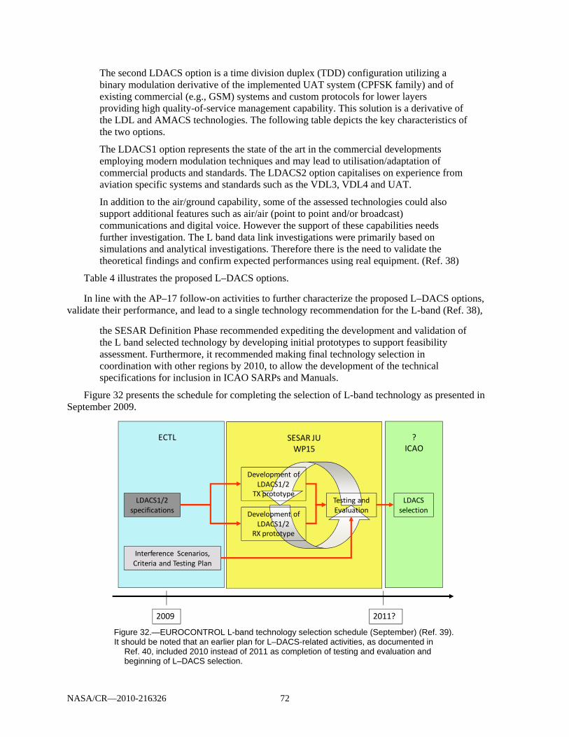
NASA/CR—2010-216326 72
The second LDACS option is a time division duplex (TDD) configuration utilizing a binary modulation derivative of the implemented UAT system (CPFSK family) and of existing commercial (e.g., GSM) systems and custom protocols for lower layers providing high quality-of-service management capability. This solution is a derivative of the LDL and AMACS technologies. The following table depicts the key characteristics of the two options.
The LDACS1 option represents the state of the art in the commercial developments employing modern modulation techniques and may lead to utilisation/adaptation of commercial products and standards. The LDACS2 option capitalises on experience from aviation specific systems and standards such as the VDL3, VDL4 and UAT.
In addition to the air/ground capability, some of the assessed technologies could also support additional features such as air/air (point to point and/or broadcast) communications and digital voice. However the support of these capabilities needs further investigation. The L band data link investigations were primarily based on simulations and analytical investigations. Therefore there is the need to validate the theoretical findings and confirm expected performances using real equipment. (Ref. 38)
Table 4 illustrates the proposed L–DACS options. In line with the AP–17 follow-on activities to further characterize the proposed L–DACS options,
validate their performance, and lead to a single technology recommendation for the L-band (Ref. 38),
the SESAR Definition Phase recommended expediting the development and validation of the L band selected technology by developing initial prototypes to support feasibility assessment. Furthermore, it recommended making final technology selection in coordination with other regions by 2010, to allow the development of the technical specifications for inclusion in ICAO SARPs and Manuals.
Figure 32 presents the schedule for completing the selection of L-band technology as presented in September 2009.
Figure 32.—EUROCONTROL L-band technology selection schedule (September) (Ref. 39). It should be noted that an earlier plan for L–DACS-related activities, as documented in
Ref. 40, included 2010 instead of 2011 as completion of testing and evaluation and beginning of L–DACS selection.
SESAR JUWP15
?ICAO
ECTL
LDACS1/2specifications
Interference Scenarios,Criteria and Testing Plan
Development ofLDACS1/2
TX prototype
Development ofLDACS1/2
RX prototype
Testing andEvaluation
LDACSselection
2009 2011?

NASA/CR—2010-216326 73
To complete the selection of the L–DACS, the detailed specifications for L–DACS1 and L–DACS2 were to be developed in 2009 along with interference scenarios, compatibility criteria, and a testing plan. These activities were proposed to be followed by SESAR joint undertaking (JU) prototype development, testing, and evaluation in to assess the overall performance of L–DACS1 and L–DACS2 systems. The selection of the most appropriate system could then be considered in a global framework involving ICAO.
Figure 12 in Section 3.0 shows the target schedule for expedited L–DACS development as presented in the AP–17 final report in November 2007 (Ref. 20).
This schedule was initially used by the FAA to plan its support activities, especially those related to interference assessment and testing.
At this time, one or more prototypes for L–DACS systems are still being developed. While the activities proposed earlier are still planned, their execution is delayed. As noted above, due to current inactivity of European partners, FAA schedule and activities have been adjusted accordingly.
Figure 33 depicts a communication navigation surveillance/air traffic management (CNS/ATM) roadmap as presented in European Air Traffic Management Master Plan (Ref. 41).
The L-band system is identified as providing capability level 4 to complement VDL–2, in support of more demanding services. It is proposed to allow moving from airspace to trajectory-based operations. The required research and development tasks include
Developing and validating A/G architecture for the new L-band link Assessing and supporting consolidation of European-wide spectrum requirements Developing and validating the selection of the technology for the future terrestrial L-band
datalink by developing initial prototypes to support feasibility assessment By 2010, in coordination with other regions (e.g., United States), making final technology
selection to allow the development of the technical specifications to be included in ICAO SARPS and manual
It should be noted that while system implementation is not proposed to start until 2016 with the R&D
shown beginning 2013, technology selection is still planned to be completed by 2010.

NASA/CR—2010-216326 74
Figure 33.—SESAR CNS systems and infrastructure roadmap (Ref. 41). Acronyms are defined in Appendix A.
7.2.3 L-Band System Implementation
The COCR identifies two phases of implementation of operational service capabilities. The first phase is based on existing or emerging data communications services and is scheduled to be completed around 2020. Initial steps under this phase are currently being implemented. During the second phase data communications is to become the primary means of A/G communication supporting increased automation in the aircraft and on the ground.
The L-band system is proposed to be introduced during the second phase of FRS implementation. It should support A/G as well as A/A communications. A/A communications would be considered a second stage following the A/G communications implementation.
While data communication is a primary objective for the proposed system, digital voice may be considered in the future set of capabilities.
Figure 34 shows the communications links included for the planned L-band system.
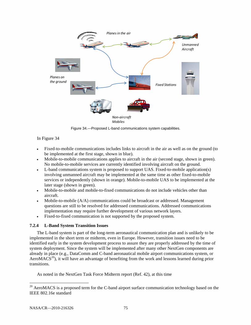
NASA/CR—2010-216326 75
Figure 34.—Proposed L-band communications system capabilities.
In Figure 34 Fixed-to-mobile communications includes links to aircraft in the air as well as on the ground (to
be implemented at the first stage, shown in blue). Mobile-to-mobile communications applies to aircraft in the air (second stage, shown in green).
No mobile-to-mobile services are currently identified involving aircraft on the ground. L-band communications system is proposed to support UAS. Fixed-to-mobile application(s)
involving unmanned aircraft may be implemented at the same time as other fixed-to-mobile services or independently (shown in orange). Mobile-to-mobile UAS to be implemented at the later stage (shown in green).
Mobile-to-mobile and mobile-to-fixed communications do not include vehicles other than aircraft.
Mobile-to-mobile (A/A) communications could be broadcast or addressed. Management questions are still to be resolved for addressed communications. Addressed communications implementation may require further development of various network layers.
Fixed-to-fixed communication is not supported by the proposed system.
7.2.4 L-Band System Transition Issues
The L-band system is part of the long-term aeronautical communication plan and is unlikely to be implemented in the short term or midterm, even in Europe. However, transition issues need to be identified early in the system development process to assure they are properly addressed by the time of system deployment. Since the system will be implemented after many other NextGen components are already in place (e.g., DataComm and C-band aeronautical mobile airport communications system, or AeroMACS20), it will have an advantage of benefiting from the work and lessons learned during prior transitions.
As noted in the NextGen Task Force Midterm report (Ref. 42), at this time
20 AeroMACS is a proposed term for the C-band airport surface communication technology based on the IEEE 802.16e standard
Planes in the air
Planes on the ground
Unmanned Aircraft
Non‐aircraft Mobiles
Fixed Stations
NASA/CR—2010-216326 76
the NextGen Task Force is focusing on the difficult transition issues that must be addressed to achieve the goals of improving the performance of the NAS while transitioning to NextGen. This will require us to address policies, procedures, operational approval processes, certification, regulatory guidance, training, criteria and standards—along with technology. Most importantly, we must put ourselves in a position to clearly demonstrate improvements in capacity, efficiency and access in the next 3 to 5 years so the operator community will have the confidence and the commitment to make the business case for the technology investments needed for beyond 2015. We have a plan; now it is time to begin the really difficult work of execution, which is much more difficult than planning because it requires commitment to action.
A similar task force or entity focusing on operational transition for the long-term communication systems, including the L-band, should address the same operational capabilities elements considered for the mid-term transition (Ref. 42):
Change in roles (e.g., pilot, controller) Required technology and equipage Available technology and equipage Required decision support tools Required policy change (DOT general, FAA general, FAA air traffic, FAA–AVS (advisory
services), DoD) Required new procedures Implementation bandwidth Required airspace changes Required standards Required operational approval Required certification Political risk Links to planning documents Required training Other challenges Environmental considerations Although a NextGen task force is not intended to produce technical guidance and requirements
recommendations, its focus on government-to-industry consensus to resolve critical integration and implementation issues maximizes benefits of NextGen operational capabilities and aids in resolving business- and investment-related issues associated with implementing those capabilities.
Technical details are still being developed and operational capabilities are not yet fully defined for the L-band system. A final selection of services chosen as applications for the new system will greatly influence transition time and process. When implemented, the system will provide a long-term capacity solution and will allow the introduction of new communications services. A gradual transition to the new band and services will lead to mixed equipage aircrafts cooperating for extensive period of time. A special consideration is given to the transition of UAS operations. As noted by the RTCA SC–203 (Ref. 34),
One aspect of the way ahead is to consider that not all UAS CC links need to operate in the same frequency bands or use the same technologies. All that is required is sufficient connectivity to allow individual UAs to operate in their desired airspace. Thus an evolutionary process is possible without mandating migration of existing UAS operations to the new bands and transmission systems as they become available. If an evolutionary

NASA/CR—2010-216326 77
process is chosen, some communications technologies could be made available for UAS operations quickly while others are being developed. It is important to note that with an evolutionary process, the short-term solutions will possibly have limited capacity so expansion of UAS operations beyond a limited capacity will require the introduction of the next solution.
7.2.5 Relationship between the Proposed Systems
Figure 35 illustrates how the proposed L-band system may relate to the VDL–2 and/or the AeroMACS systems.
Figure 35.—Relationship between the L-band system and the VDL–2 and C-band systems.
Acronyms are defined in Appendix A.
In Figure 35 An aircraft on the ground may receive some services over an AeroMACS system and other
services over a VDL–2 and/or L-band An aircraft in the air may be on VDL–2 only, both VDL–2 and L-band or L-band-only systems
depending on services and transition stage A/A communications is shown as being provided on L-band only UAS- related services are assumed and shown as provided on L-band L-band and C-band systems are “connected” through the ground network only. L-band systems
will not access C-band sensors or otherwise communicate with the C-band fixed assets directly
As it may take 10 years or more to equip all aircraft with the new FRS equipment, operation on different data links should be expected for many years and planed for accordingly. Transition issues will include but not limited to the controllers adjusting communications procedures from voice to a mixed voice/data to potentially data-only communications for some information transfers. With respect to voice vs. data communications, it should be noted, that voice communications are likely to remain as a backup in case of data communications failures and “voice-based procedures will remain as an alternative form of
ANSP Info Servers
C‐Band SystemAeroMACSNetwork
VDL‐2 System
L‐Band System
Fixed Assets/Sensors
Ground Network
Plane on the ground
Planes in the airUnmanned Aircraft
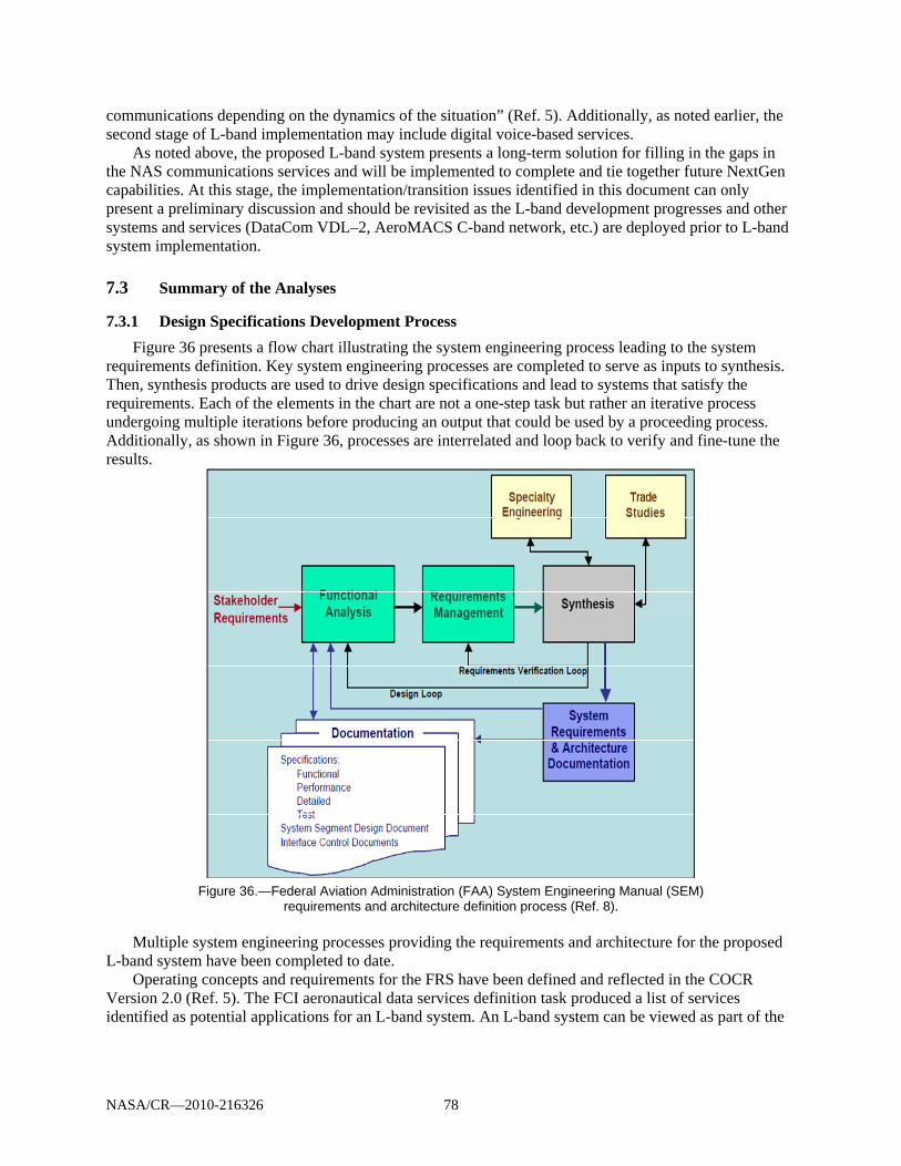
NASA/CR—2010-216326 78
communications depending on the dynamics of the situation” (Ref. 5). Additionally, as noted earlier, the second stage of L-band implementation may include digital voice-based services.
As noted above, the proposed L-band system presents a long-term solution for filling in the gaps in the NAS communications services and will be implemented to complete and tie together future NextGen capabilities. At this stage, the implementation/transition issues identified in this document can only present a preliminary discussion and should be revisited as the L-band development progresses and other systems and services (DataCom VDL–2, AeroMACS C-band network, etc.) are deployed prior to L-band system implementation.
7.3 Summary of the Analyses
7.3.1 Design Specifications Development Process
Figure 36 presents a flow chart illustrating the system engineering process leading to the system requirements definition. Key system engineering processes are completed to serve as inputs to synthesis. Then, synthesis products are used to drive design specifications and lead to systems that satisfy the requirements. Each of the elements in the chart are not a one-step task but rather an iterative process undergoing multiple iterations before producing an output that could be used by a proceeding process. Additionally, as shown in Figure 36, processes are interrelated and loop back to verify and fine-tune the results.
Figure 36.—Federal Aviation Administration (FAA) System Engineering Manual (SEM)
requirements and architecture definition process (Ref. 8).
Multiple system engineering processes providing the requirements and architecture for the proposed L-band system have been completed to date.
Operating concepts and requirements for the FRS have been defined and reflected in the COCR Version 2.0 (Ref. 5). The FCI aeronautical data services definition task produced a list of services identified as potential applications for an L-band system. An L-band system can be viewed as part of the
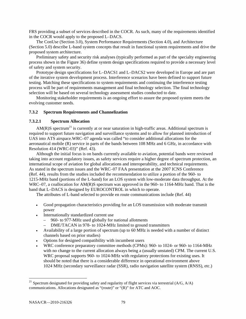
NASA/CR—2010-216326 79
FRS providing a subset of services described in the COCR. As such, many of the requirements identified in the COCR would apply to the proposed L–DACS.
The ConUse (Section 3.0), System Performance Requirements (Section 4.0), and Architecture (Section 5.0) describe L-band system concepts that result in functional system requirements and drive the proposed system architecture.
Preliminary safety and security risk analyses (typically performed as part of the specialty engineering process shown in the Figure 36) define system design specifications required to provide a necessary level of safety and system security.
Prototype design specifications for L–DACS1 and L–DACS2 were developed in Europe and are part of the iterative system development process. Interference scenarios have been defined to support future testing. Matching these specifications to system requirements and continuing the interference testing process will be part of requirements management and final technology selection. The final technology selection will be based on several technology assessment studies conducted to date.
Monitoring stakeholder requirements is an ongoing effort to assure the proposed system meets the evolving customer needs.
7.3.2 Spectrum Requirements and Channelization
7.3.2.1 Spectrum Allocation
AM(R)S spectrum21 is currently at or near saturation in high-traffic areas. Additional spectrum is required to support future navigation and surveillance systems and to allow for planned introduction of UAS into ATS airspace.WRC–07 agenda was called “to consider additional allocations for the aeronautical mobile (R) service in parts of the bands between 108 MHz and 6 GHz, in accordance with Resolution 414 (WRC-03)” (Ref. 43).
Although the initial focus is on bands currently available to aviation, potential bands were reviewed taking into account regulatory issues, as safety services require a higher degree of spectrum protection, an international scope of aviation for global allocations and interoperability, and technical requirements. As stated in the spectrum issues and the WRC–07 FAA presentation at the 2007 ICNS Conference (Ref. 44), results from the studies included the recommendation to utilize a portion of the 960- to 1215-MHz band (portions of the L-band) for an LOS system with low-moderate data throughput. At the WRC–07, a coallocation for AM(R)S spectrum was approved in the 960- to 1164-MHz band. That is the band that L–DACS is designed by EUROCONTROL in which to operate.
The attributes of L-band selected to provide en route communications include (Ref. 44) Good propagation characteristics providing for an LOS transmission with moderate transmit
power Internationally standardized current use
– 960- to 977-MHz used globally for national allotments – DME/TACAN in 978- to 1024-MHz limited to ground transmitters
Availability of a large portion of spectrum (up to 60 MHz is needed with a number of distinct channels based on prior studies)
Options for designed compatibility with incumbent users WRC conference preparatory committee methods (CPMs): 960- to 1024- or 960- to 1164-MHz
with no change to the current allocation always being a (usually unstated) CPM. The current U.S. WRC proposal supports 960- to 1024-MHz with regulatory protections for existing uses. It should be noted that there is a considerable difference in operational environment above 1024 MHz (secondary surveillance radar (SSR), radio navigation satellite system (RNSS), etc.)
21 Spectrum designated for providing safety and regularity of flight services via terrestrial (A/G, A/A) communications. Allocations designated as “(route)” or “(R)” for ATC and AOC.
NASA/CR—2010-216326 80
Further analysis of industry papers and ITU-R-related activities should be conducted to assess the latest spectrum recommendations. This activity is recommended for Phase II.
7.3.2.2 Interference Studies
Several civil and military systems operate, or will operate, in parts of the 960- to 1215-MHz band, as shown in Figure 37. Detailed compatibility analyses are required between the proposed L-band system and the incumbents.
Figure 37.—Systems operating in the 960- to 1215-MHz band (Ref. 45). Copyright Mileridge Ltd.; used with
permission. Acronyms are defined in Appendix A.
Several studies have been conducted in Europe to characterize L-band frequency environment and identify potential interference problems.
The B–AMC22 Project Deliverable D1 (Ref. 45)—Spectrum Characterization—identifies and analyzes three spectrum sharing options offering the following conclusions:
Option 1: B–AMC utilizing spectrum between successive DME channels deploying the proposed
system as an inlay in the L-band (960 to 1164 MHz). B–AMC frequency planning is required to implement the system utilizing channels between successive DME channels.
Option 2: assigning frequencies to B–AMC channels in areas where they are not used locally by DME. A combination of selecting B–AMC channels with a certain frequency offset from nearby DME systems, and ensuring that a minimum separation distance is maintained to allow avoiding causing interference to DME, SSR, and UAT.
Option 3: utilizing the lower part of the band (960 to 978 MHz) for B–AMC considering interference with the Global System for Mobile Communications (GSM), which is operated in the lower adjacent band. The report notes insufficient information available to determine whether it is technically feasible to implement this option.
The subsequent systematic interference investigations report documents the impact of DME
interference onto the performance of the B–AMC system to determine the level of tolerable interference power. It concludes that (Ref. 46)
22 As noted in Figure 37, B–AMC and TIA–902 (P34) provide the basis for L–DACS1 technology.
NASA/CR—2010-216326 81
When selecting appropriate centre frequencies for the B–AMC system, all interferers with the power level below –100 dBm can be neglected. Moreover, the interference situation in each channel can be simplified to one representative interferer with representative power and duty cycle, hence facilitating the ranking of different candidate centre frequencies with respect to interference condition. The conducted studies highlighted the need for interference testing. Proposed L-band interference
scenarios (Ref. 47) were developed by DLR to define the procedures for generating interference scenarios that model interference from the incumbents to the proposed L-band system. Though interference depends on many factors including a particular frequency, the document defines general procedures that should apply to any L-band frequency range.
As the DME systems present the main source of interference in the aeronautical L-band, strong emphasis is put on modeling interference with these systems. The document describes creating a DME interference simulator, discusses the methodology for generating interference scenarios taking into account DME ground stations, and investigates interference originating from aircraft interrogating these stations. Examples of interference scenarios for B–AMC reverse and/or forward links are given as appropriate. Interference from other L-band systems is addressed by modeling JTIDS, UAT, and SSR pulses.
An additional study has been conducted by Roke Manor to investigate coexistence issues between DME and a B–AMC system providing a future A/G communication service in the L-band while assessing relevant system design issues. The DME and B–AMC coexistence study report draws the following conclusions and makes recommendations to EUROCONTROL (Ref. 48. Copyright Roke Manor Research; used with permission):
As it is not clear whether benefits of OFDM on the reverse link overweight the need for a highly
linear airborne power amplifier, it is recommended to examine methods to reduce peak-to-mean ratio of OFDM in the reverse link (e.g., by using a single carrier FDMA or a similar technique).
Interference link budgets indicate that coexistence of B–AMC and DME systems is possible with a guard band of one DME channel between them. It is recommended to investigate whether key FCS system parameters could be selected in line with a commercial OFDM standard (e.g., WiMAX) to an extent that would facilitate partial reuse of COTS solutions.
Without a guard band, and disregarding the effects of terrain, existing DME stations in Europe could cause up to –75 dBm peak and –87 dBm mean interference into a B–AMC receiver at a 9000-m altitude, assuming optimal frequency planning. It is recommended to assess whether it is possible to have the required guard band between DME and B–AMC through frequency coordination, taking into account the DME deployment in Europe and the effects of terrain.
The draft B–AMC frequency plan is the latest in the series of deliverables that address interference
and compatibility issues (Ref. 49).
The draft frequency planning approach described in this report is restricted to the scenarios involving only B–AMC and DME systems. Moreover, as with current DME/TACAN planning, only ground-air scenarios with airborne victim DME and B–AMC receivers have been investigated. As the En-Route coverage is the most demanding case with respect to the usage of spectral resources, this case has been investigated in detail—TMA and airport planning have been delegated to the future work.
The document specifies basic frequency planning rules according to B–AMC Deployment Option 2—inlay deployment with a 0.5-MHz frequency offset between B–AMC and existing DME channels and presents an initial draft frequency plan for the deployment of B–AMC within Europe (Ref. 49. Copyright University of Salzburg; used with permission.)
NASA/CR—2010-216326 82
Within the initial planning exercise, large 120 nm En-Route B–AMC cells have been considered, with ground B–AMC TX power of +38 dBm. As expected, simultaneously considering the interference from the B–AMC GS [ground station] towards airborne DME receivers and the interference from DME GSs towards airborne B–AMC receivers have imposed strong restrictions upon the pool of available B–AMC frequencies. In the consequence, for some B–AMC cells an appropriate B–AMC inlay frequency could not be found (at least not without re-arranging DME allocations). In order to further increase the percentage of assignable B–AMC cells, the following supplementary conceptual refinements have been discussed:
Extension of the FL/RL B–AMC frequency range (985.5- to 1008.5-MHz to 979.5- to 1018.5-MHz)
Reduction of B–AMC cell radius for some B–AMC cells (from 120 nm to 60 nm), with the corresponding reduction of the B–AMC TX power (from 38 dBm to 32 dBm)
Placement of B–AMC en route ground stations at sufficient distance from DME stations (fine adjustment of B–AMC ground station positions)
Investigation of an alternative B–AMC “overlay” concept with 0-MHz frequency offset to existing DME frequencies.
The set of scenarios for several combinations of proposed improvements has been developed and investigated. The following general conclusions apply to that case:
The B–AMC en route system can be operated as a cellular system with different cell sizes, e.g., by using 120 nm B–AMC cells (T–cells) and 60 nm cells (S–cells).
For a large number of B–AMC cells in Europe, appropriate B–AMC candidate frequencies can be determined, which do not violate the stringent interference requirements (–106.6-dBm threshold with 12-dB margin) towards the DME system.
Taking into account the dense distribution of DME and TACAN stations in Europe, as an overall conclusion the obtained preliminary results are quite positive. However, detailed evaluation of the B–AMC interference situation is required, covering all interference scenarios mentioned in subchapter 3.1.3 [of Draft B–AMC Frequency Plan report] and considering appropriate reuse distances.
Recommendations
Investigating other interference cases that could not be considered in this report (A/A and A/G) and their impact upon frequency planning should be included as a topic for future work.
Common agreement about the acceptable interference threshold for DME/B–AMC receivers should be achieved in the environment with multiple interferers.
The draft criteria for frequency planning used in this work should be refined, dependent on the outcome of the above activities.
All the studies described in this section were conducted for B–AMC/L–DACS1 systems. While
general spectrum constraints will apply to any L-band system regardless of the technology, studies for L–DACS2 need to be conducted should this technology be considered for a proposed L-band system. Common assumptions, metrics, and interference criteria for both candidate technologies should be established and followed to enable an objective comparison between them.
NASA/CR—2010-216326 83
7.3.3 Design Specifications and Prototype Development
EUROCONTROL has funded these studies to provide the specifications for the L–DACS. The following reports were created for L–DACS1 and L–DACS2 candidate systems identified in ICAO and in the SESAR definition phase to support the FCI in the continental en route and TMA environments:
L–DACS1 System Definition Proposal: Deliverable D3–Design Specifications for L–DACS1
Prototype, Edition 1.0, April 27 2009, Frequentis, DLR, University of Salzburg, and Selex (Ref. 50)
LDACS1 D2 Final Deliverable Edition: 1.0, Frequentis, DLR, University of Salzburg, and Selex, February 13, 2009 (Ref. 51)
L–DACS2 System Definition Proposal: Deliverable D1 Edition 0.34, EGIS AVIA, March 11, 2009 (Ref. 52)
L–DACS2 Transmitter and Receiver Prototype Equipment Specifications: Deliverable D3 Edition 1.2, EGIS AVIA, June 18, 2009 (Ref. 53)
System specification studies capture the parameters relevant for the prototype development. The
prototypes are (Ref. 50)
aiming at demonstrating that the L–DACS system does not introduce unacceptable interference towards receiver of other L-band systems, as well that the L–DACS system itself satisfactory operates under presence of L-band interference coming from such external systems.
Prototype development and subsequent system testing will facilitate final L-band system technology selection. Both, ground and airborne, as well as cosite23 scenarios will be investigated. Criteria and scenarios study key deliverable will include
Compatibility criteria Testing plan Interference scenarios Interference scenarios and use of suppression bus for a co-site case
Deliverables are to be finalized in September 2009 (Ref. 39). Continued research, development and testing activities closely coordinated between
EUROCONTROL and FAA will allow realization of desired system capabilities while adhering to the strictest safety and security requirements.
23 DME receiver and FRS transmitter on board an aircraft

NASA/CR—2010-216326 85
Appendix A.—Acronyms and Abbreviations
The following list identifies acronyms and abbreviations used throughout this document.
A/A air to air
A/G air to ground
ACARS Aircraft Communications Addressing and Reporting System
ACL air traffic control clearance
ACSTS Aerospace Communications Systems Technical Support
ADAS AWOS Data Acquisition Service
ADDS Aviation Digital Data Service
ADS automatic dependent surveillance
ADS–B automatic dependent surveillance—broadcast
ADS–C automatic dependent surveillance—contract
ADS–R automatic dependent surveillance—rebroadcast
AEEC Airlines Electronic Engineering Committee
AeroMACS Aeronautical Mobile Airport Communications System
AFB Air Force Base
AFIS airport/aerodrome flight information service
AGDLGMS Air Ground Data Link Ground Management System
AIRSEP air-to-air self separation
AMHS air traffic services message handling system
AM(R)S aeronautical mobile (route) service
AMS(R)S aeronautical mobile satellite (route) service
AMACS all-purpose multichannel aviation communication system
ANSP air navigation service provider
AOA autonomous operations area
AOC aeronautical (airline) operational control
AP–17 Action Plan 17
APT Airport
ARINC Aeronautical Radio Incorporated
ARNS Aeronautical Radio Navigation Services
ARTCC air route traffic control center
ASDE–X airport surface detection equipment, model X

NASA/CR—2010-216326 86
ATC air traffic control
ATCRBS air traffic control radar beacon system
ATCSCC air traffic control system command center
ATCT air traffic control tower(s)
ATFCM air traffic flow and capacity management
ATIS Automatic Terminal Information Service
ATM air traffic management
ATO Air Traffic Organization
ATS air traffic services
ATSP air traffic service provider
ATSU air traffic service unit
AVS advisory services
AWOS Automated Weather Observing System
B–AMC Broadband Aeronautical Multicarrier Communication System
BASOP base operations
BLOS beyond line of sight
BUEC backup emergency communications
C&P crossing and passing
CATM collaborative air traffic management
CC control and communications
CDA continuous descent arrivals or continuous descent approach
CDM collaborative decision making
CDTI cockpit display of traffic information
CMU communications management unit
CNS communication, navigation, surveillance
COCR communications operating concepts and requirements
ConOps concepts of operations
ConUse concepts of use
CPFSK continuous phase frequency shift keying
CPM conference preparatory committee method
CS control station
CTA controlled times of arrival
Data Comm Federal Aviation Administration Data Communications Program

NASA/CR—2010-216326 87
DC data communications
DCL departure clearance
DCNS data communications networks services
DME distance measuring equipment
DoD Department of Defense
D–ATIS digital automatic terminal information service
D–ORIS data link operational route information service
D–OTIS data link operational terminal information service
D–RVR data link runway visual range
D–SIG data link surface information and guidance
D–SIGMET Data Link Significant Meteorological Information
DSC downstream clearance
DSS decision support system
D–TAXI data link taxi clearance
DTS Dedicated Telecom Services
DYNAV dynamic route availability
EA enterprise architecture
ECS emergency communications system
EIS emergency information services
ENR en route
ERAM en route automation modernization
ETVS enhanced terminal voice switch
EUROCONTROL European Organisation for the Safety of Air Navigation
FAA Federal Aviation Administration
FANS Future Air Navigation System
FCI future communications infrastructure
FCS Future Communications Study
FDD frequency-division duplex
FDPS flight data processing system
FFBD functional flow block diagram
FIS flight information service
FLIPCY flight plan consistency
FMS flight management system

NASA/CR—2010-216326 88
FOC Flight Operations Center
FPR final program requirements
FRS future radio system
FY fiscal year
GA general aviation
G/A ground-to-air
G/G ground-to-ground
GBAS ground-based augmentation system
GBT ground-based transceiver
GI general information
GIS geographical information system
GMSK Gaussian minimum shift keying
GNI ground network interface
GSM Global System for Mobile Communications
HVAC heating, ventilation, and air conditioning
ICAO International Civil Aviation Organization
IDS information display system
IEEE Institute of Electrical and Electronics Engineers, Inc
IFR instrument flight rules
ILS instrument landing system
IM infrastructure management
IOC initial operating capability
IP internet protocol
ISE information security engineering
ITP in-trail procedures
ITU International Telecommunication Union
IWP integrated work plan
JPDO Joint Planning and Development Office
JTIDS Joint Tactical Information Distribution System
L–DACS L-Band Digital Aeronautical Communications System
LDL L-Band digital link
LOS line of sight
M&C monitoring and control
NASA/CR—2010-216326 89
M&S merging and spacing
MAC Media Access Control
MTBF mean time between failures
NAS National Airspace System
NASA National Aeronautics and Space Administration
NASCR NAS common reference
NAVAIDS navigation aids
NEXRAD Next Generation Radar
NEXCOM Next Generation Air/Ground Communications
NextGen Next Generation Air Transportation System
NNEW NextGen Network Enabled Weather
NOCC National Operations Control Center
NOTAM Notice to Airmen
OFDM orthogonal frequency division multiplexing
OI operational improvement
OPA operational performance assessment
ORP oceanic, remote, polar
OSED operational services and environment description
OV operational view
PAIRAPP paired approaches
PIREP pilot report
PLA project-level agreement
PPD pilot preferences downlink
QoS quality of service
RAPCO radar approach control
RCAG remote communications air/ground facility
RCE–C remote control equipment at control site
RCE–R remote control equipment at remote (transmitter/receiver) site
RCP required communication performance
RCTP required communication technical performance
RDVS rapid deployment voice switch
RE&D research, engineering and development
RF radiofrequency

NASA/CR—2010-216326 90
RFI radiofrequency interference
RJ regional jet
RMS remote-monitoring subsystem
RNAV area navigation
RNP required navigation performance
RNSS Radio Navigation Satellite System
RTCA RTCA, Inc. (founded as Radio Technical Commission for Aeronautics)
RTR remote transmitter/receiver
RVR runway visual range
S&A sense and avoid
SAMS special use airspace management system
SARPs standards and recommended practices
SAP system access parameter
SATCOM satellite communication
SBAS satellite-based augmentation system
SE system engineering
SEM System Engineering Manual
SESAR Single European Sky ATM Research
SITA Société Internationale de Télécommunications Aéronautiques
SOA service-oriented architecture
SOC Service Operations Center
SOCC Security Operations Control Center
SPR safety and performance requirements
SR system requirement
SSE system safety engineering
SSR secondary surveillance radar
SUA special use airspace
SV system view
SWIM System Wide Information Management
SYSCO system-supported coordination
TACAN tactical air navigation
TAP tailored arrival procedure
TBA traffic information broadcast by aircraft
NASA/CR—2010-216326 91
TBO trajectory-based operations
TCAS Traffic Collision Avoidance System
TDD time-division duplex
TDLS Terminal Data Link System
TFM traffic flow management
TFR temporary flight restrictions
TIA Telecommunications Industry Association
TIS–B traffic information services, broadcast
TM traffic management
TMA terminal maneuvering area
TRACON Terminal Radar Approach Control Facility
TRL technical readiness level
TSOs technical standard orders
TVS terminal voice switch
UA unmanned aircraft
UAS unmanned aircraft system
UAT universal access transceiver
UHF ultra high frequency
URCO urgent contact
VDL very high frequency digital link
VHF very high frequency
VoIP digital voice over internet protocol
VOR very high frequency omnidirectional radio range
WAKE wake vortex
WARP Weather and Radar Processor
WINS Weather Information Network Server
WRC World Radio Communications Conference
Wx Weather
4–D four-dimensional
4DT four-dimensional trajectory

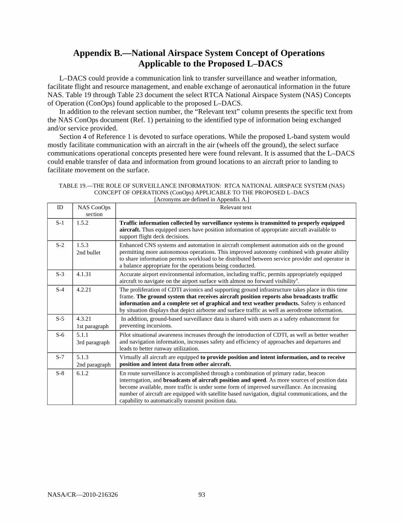
NASA/CR—2010-216326 93
Appendix B.—National Airspace System Concept of Operations Applicable to the Proposed L–DACS
L–DACS could provide a communication link to transfer surveillance and weather information, facilitate flight and resource management, and enable exchange of aeronautical information in the future NAS. Table 19 through Table 23 document the select RTCA National Airspace System (NAS) Concepts of Operation (ConOps) found applicable to the proposed L–DACS.
In addition to the relevant section number, the “Relevant text” column presents the specific text from the NAS ConOps document (Ref. 1) pertaining to the identified type of information being exchanged and/or service provided.
Section 4 of Reference 1 is devoted to surface operations. While the proposed L-band system would mostly facilitate communication with an aircraft in the air (wheels off the ground), the select surface communications operational concepts presented here were found relevant. It is assumed that the L–DACS could enable transfer of data and information from ground locations to an aircraft prior to landing to facilitate movement on the surface.
TABLE 19.—THE ROLE OF SURVEILLANCE INFORMATION: RTCA NATIONAL AIRSPACE SYSTEM (NAS)
CONCEPT OF OPERATIONS (ConOps) APPLICABLE TO THE PROPOSED L–DACS [Acronyms are defined in Appendix A.]
ID NAS ConOps section
Relevant text
S-1 1.5.2 Traffic information collected by surveillance systems is transmitted to properly equipped aircraft. Thus equipped users have position information of appropriate aircraft available to support flight deck decisions.
S-2 1.5.3 2nd bullet
Enhanced CNS systems and automation in aircraft complement automation aids on the ground permitting more autonomous operations. This improved autonomy combined with greater ability to share information permits workload to be distributed between service provider and operator in a balance appropriate for the operations being conducted.
S-3 4.1.31 Accurate airport environmental information, including traffic, permits appropriately equipped aircraft to navigate on the airport surface with almost no forward visibilitya.
S-4 4.2.21 The proliferation of CDTI avionics and supporting ground infrastructure takes place in this time frame. The ground system that receives aircraft position reports also broadcasts traffic information and a complete set of graphical and text weather products. Safety is enhanced by situation displays that depict airborne and surface traffic as well as aerodrome information.
S-5 4.3.21 1st paragraph
In addition, ground-based surveillance data is shared with users as a safety enhancement for preventing incursions.
S-6 5.1.1 3rd paragraph
Pilot situational awareness increases through the introduction of CDTI, as well as better weather and navigation information, increases safety and efficiency of approaches and departures and leads to better runway utilization.
S-7 5.1.3 2nd paragraph
Virtually all aircraft are equipped to provide position and intent information, and to receive position and intent data from other aircraft.
S-8 6.1.2 En route surveillance is accomplished through a combination of primary radar, beacon interrogation, and broadcasts of aircraft position and speed. As more sources of position data become available, more traffic is under some form of improved surveillance. An increasing number of aircraft are equipped with satellite based navigation, digital communications, and the capability to automatically transmit position data.
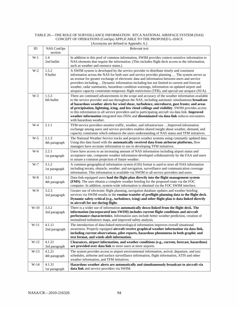
NASA/CR—2010-216326 94
TABLE 20.—THE ROLE OF SURVEILLANCE INFORMATION: RTCA NATIONAL AIRSPACE SYSTEM (NAS)
CONCEPT OF OPERATIONS (ConOps) APPLICABLE TO THE PROPOSED L–DACS [Acronyms are defined in Appendix A.]
ID NAS ConOps section
Relevant text
W-1 1.4 2nd bullet
In addition to this pool of common information, SWIM provides context-sensitive information to NAS elements that require the information. (This includes flight deck access to the information, such as weather and resource status.)
W-2 1.5.2 9 bullet
A SWIM system is developed by the service provider to distribute timely and consistent information across the NAS for both user and service provider planning … The system serves as an avenue for greater exchange of electronic data and information between users and service providers including… Dynamic information including but not limited to current and forecast weather, radar summaries, hazardous condition warnings, information on updated airport and airspace capacity constraints temporary flight restrictions (TFR), and special use airspace (SUA).
W-3 1.5.3 6th bullet
There are continued advancements in the scope and accuracy of the weather information available to the service provider and use throughout the NAS, including automatic simultaneous broadcast of hazardous weather alerts for wind shear, turbulence, microburst, gust fronts; and areas of precipitation, lightning, icing, and low cloud ceilings and visibility. SWIM provides access to this information to all service providers and to participating aircraft via data link. Improved weather information integrated into DSSs and disseminated via data link reduces encounters with hazardous weather.
W-4 2.1.1 TFM service providers monitor traffic, weather, and infrastructure …Improved information exchange among users and service providers enables shared insight about weather, demand, and capacity constraints which enhances the users understanding of NAS status and TFM initiatives.
W-5 2.1.3 4th paragraph
The National Weather Service tracks and projects weather systems using constantly updated data. Using this data fused with the automatically received data from airborne platforms, flow managers have accurate information to use in developing TFM initiatives.
W-6 2.2.1 1st paragraph
Users have access to an increasing amount of NAS information including airport status and acceptance rate, composite weather information developed collaboratively by the FAA and users to assure a common projection of future weather.
W-7 3.1.2 1st paragraph
A common geographical information system (GIS) format is used to store all NAS information including terrain, obstacle, weather, and navigation, surveillance and communication coverage information. This information is available via SWIM to all service providers and users.
W-8 3.2.1 4th paragraph
Data-link-equipped users load the flight plan directly into the flight management system (FMS). The user obtains a complete weather briefing for the proposed route via the FOC computer. In addition, system-wide information is obtained via the FOC SWIM interface.
W-9 3.2.3 3rd paragraph
Greater use of electronic flight planning, navigation database updates and weather briefing services via SWIM results in the routine transfer of preflight planning data to the flight deck. Dynamic safety-critical (e.g., turbulence, icing) and other flight plan is data linked directly to aircraft for use during flight.
W-10 3.3.2 3rd paragraph
There is a wider use of information automatically down-linked from the flight deck. The information (incorporated into SWIM) includes current flight conditions and aircraft performance characteristics. Information uses include better weather prediction, creation of normalized turbulence maps, and improved safety analysis.
W-11 4.1.11 2nd paragraph
The introduction of data-linked meteorological information improves overall situational awareness. Properly equipped aircraft receive graphical weather information via data link, including current observations, pilot reports, hazardous phenomena in both graphic and text format, and winds aloft information.
W-12 4.1.21 3rd paragraph
Clearances, airport information, and weather conditions (e.g., current, forecast, hazardous) are provided over data link to more users at more airports.
W-13 4.1.21 4th paragraph
The system provides access to airport environmental information, arrival, departure, and taxi schedules, airborne and surface surveillance information, flight information, ATIS and other weather information, and TFM initiatives.
W-14 4.1.31 1st paragraph
Hazardous weather alerts are automatically and simultaneously broadcast to aircraft via data link and service providers via SWIM.
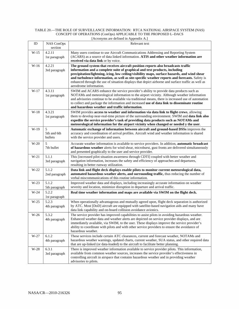
NASA/CR—2010-216326 95
TABLE 20.—THE ROLE OF SURVEILLANCE INFORMATION: RTCA NATIONAL AIRSPACE SYSTEM (NAS) CONCEPT OF OPERATIONS (ConOps) APPLICABLE TO THE PROPOSED L–DACS
[Acronyms are defined in Appendix A.] ID NAS ConOps
section Relevant text
W-15 4.2.11 1st paragraph
Many users continue to use Aircraft Communications Addressing and Reporting System (ACARS) as a source of data linked information. ATIS and other weather information are received via data link or by voice.
W-16 4.2.21 3rd paragraph
The ground system that receives aircraft position reports also broadcasts traffic information and a complete suite of graphical and text products, including precipitation/lightning, icing, low ceiling/visibility maps, surface hazards, and wind shear and turbulence information, as well as site-specific weather reports and forecasts. Safety is enhanced through the use of situation displays that depict airborne and surface traffic as well as aerodrome information.
W-17 4.3.11 1st paragraph
SWIM and ACARS enhance the service provider’s ability to provide data products such as NOTAMs and meteorological information to the airport vicinity. Although weather information and advisories continue to be available via traditional means, there is increased use of automation to collect and package the information and increased use of data link to disseminate routine and hazardous weather and traffic information.
W-18 4.3.21 1st paragraph
SWIM provides access to weather and information via data link to flight crews, allowing them to develop near-real-time picture of the surrounding environment. SWIM and data link also expedite the service provider’s task of providing data products such as NOTAMs and meteorological information for the airport vicinity when changed or needed y the user.
W-19 5 5th and 6th bullets
Automatic exchange of information between aircraft and ground-based DSSs improves the accuracy and coordination of arrival profiles. Aircraft wind and weather information is shared with the service provider and users.
W-20 5 7th bullet
Accurate weather information is available to service providers. In addition, automatic broadcast of hazardous weather alerts for wind shear, microburst, gust fronts are delivered simultaneously and presented graphically to the user and service provider.
W-21 5.1.1 3rd paragraph
This [increased pilot situation awareness through CDTI] coupled with better weather and navigation information, increases the safety and efficiency of approaches and departures, resulting in better runway utilization.
W-22 5.1.2 2nd paragraph
Data link and flight deck displays enable pilots to monitor current meteorological data, automated hazardous weather alerts, and surrounding traffic, thus reducing the number of verbal miscommunications of this routine information.
W-23 5.1.2 5th paragraph
Improved weather data and displays, including increasingly accurate information on weather severity and location, minimize disruption in departure and arrival traffic.
W-24 5.2.2 1st paragraph
Real time weather information and maps are available via SWIM on the flight deck.
W-25 5.2.3 4th paragraph
When operationally advantageous and mutually agreed upon, flight deck separation is authorized by ATC. Most [DoD] aircraft are equipped with satellite-based navigation aids and many have data link capability and on-board collision avoidance avionics.
W-26 5.3.2 4th paragraph
The service provider has improved capabilities to assist pilots in avoiding hazardous weather. Enhanced weather data and weather alerts are depicted on service provider displays, and are immediately available, via SWIM, to the user. These displays improve the service provider’s ability to coordinate with pilots and with other service providers to ensure the avoidance of hazardous weather.
W-27 6.1.2 4th paragraph
These services include certain ATC clearances, current and forecast weather, NOTAMs and hazardous weather warnings, updated charts, current weather, SUA status, and other required data that are up-linked (or data-loaded) to the aircraft to facilitate better planning.
W-28 6.3.1 3rd paragraph
There is improved weather information available to service provider pilots. This information, available from common weather sources, increases the service provider’s effectiveness in controlling aircraft in airspace that contains hazardous weather and in providing weather advisories to pilots.

NASA/CR—2010-216326 96
TABLE 21.—IDENTIFICATION OF THE ROLE OF FLIGHT MANAGEMENT INFORMATION—RTCA NATIONAL
AIRPSACE SYSTEM (NAS) CONCEPT OF OPERATIONS (ConOps) [Acronyms are defined in Appendix A.]
ID NAS ConOps section
Relevant text
FM-1 1.5.1 8th bullet
The high-altitude airspace permits aircraft operations along user-preferred profiles from entry through cruise to final exit. Entry to and exit from the airspace are based on preferred profiles for climb and descent. Within that airspace, aircraft operate closer to their optimum altitudes by increasing the available flight levels using 1000-ft rather than 2000-ft separation.
FM-2 1.5.2 8th bullet
Terminal-area procedures are expanded to provide increased efficiency, flexibility, predictability, and airspace accessibility. When the projected demand for volumes of airspace is at or near capacity and after collaboration between users and TFM, there are temporary route structures with transition points for moving to and from user trajectories
FM-3 1.5.2 9th bullet
A SWIM system is developed to distribute timely and consistent information….[Including]: - Flight information on each flight, including the filed flight profile and all amendments, first movement of the aircraft, wheels-up, position data in flight, touchdown time, gate or parking assignment, and engine shutdown.
FM-4 1.5.2 13th bullet
The flight planning system accommodates all uses of the airspace as the flight profile evolves to include real time SUA operations scheduling information.
FM-5 1.5.2 14th bullet
By integrating all airspace management systems, the NAS achieves the technical goal of providing in a timely manner the airspace necessary to execute the flight profile. The ATM system manages airspace based on each user's needs, including proximity to the user’s base of operations. As a result, more airspace, including special use, is made available to more users with increased efficiency.
FM-6 2.1.2. 1st paragraph
Collaboration via DSSs and intelligent agents supports negotiation of revised flight trajectories in real time.
FM-7 2.1.3
Flow-constrained areas are managed by allocating access, collaborative rerouting, and realigning sectors and associated resources.
FM-8 2.2.1 1st paragraph
Users have access to an increasing amount of NAS information, including airport status and acceptance rate and composite weather information developed collaboratively by the FAA and users to ensure a common projection of future weather. Improved individual support capabilities use investigative operations and develop individual strategies to mitigate demand-capacity imbalances and their effect on the individual user fleets. Sharing strategies with the ATCSCC allows service providers to evaluate conditions based on user intention rather than published schedules.
FM-9 2.2.1 2nd paragraph
Working with the service providers, users better manage en route congestion by collaboratively evaluating the situation, developing re-routes around the area, and providing a more refined allocation of flights to the reroutes.
FM-10 2.2.2 1st paragraph
With the increasing ability to maintain common situation awareness, users plan flight profiles that consider known constraints and provide the best advantage to their operations.
FM-11 2.2.2 2nd paragraph
… In addition, the flight planning system expands to offer users the opportunity to provide alternative profiles for flights. These alternative profiles are tested on a continuing basis as trial plans that are selected if conditions do not develop as foreseen. The users and service providers collaborate by modifying/exchanging these alternatives throughout the course of the flight.
FM-12 2.2.3 1st paragraph
…Within that constraint and allocation, the NAS has the ability to conduct a system-supported coordination (SYSCO)8 auto-negotiation of the flight profile to best meet the user's need within that user’s NAS resource allocation. The systems interactively re-plan each flight against both current constraints and any ancillary problems that arise through the execution of the initiative. For airborne flights, new profiles that do not require a tactical change to trajectory are provided to the flight deck for approval and execution and are included into the NAS as profile updates. For flights that have nearer-term tactical changes, the new profile is provided to the flight deck and service provider as trial plans and are implemented when appropriate.
FM-13 3 1st bullet
Elements of SWIM are used to obtain and distribute flight-specific data and aeronautical information, including international coordination of planned flight trajectory.
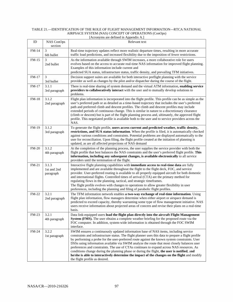
NASA/CR—2010-216326 97
TABLE 21.—IDENTIFICATION OF THE ROLE OF FLIGHT MANAGEMENT INFORMATION—RTCA NATIONAL AIRPSACE SYSTEM (NAS) CONCEPT OF OPERATIONS (ConOps)
[Acronyms are defined in Appendix A.] ID NAS ConOps
section Relevant text
FM-14 3 6th bullet
Real-time trajectory updates reflect more realistic departure times, resulting in more accurate traffic load predictions, and increased flexibility due to the imposition of fewer restrictions.
FM-15 3 2nd bullet
As the information available through SWIM increases, a more collaborative role for users evolves based on the access to accurate real-time NAS information for improved flight planning. Examples of this information include current and predicted SUA status, infrastructure status, traffic density, and prevailing TFM initiatives.
FM-17 3 3rd bullet
Decision support suites are available for both interactive preflight planning with the service provider as well as changes by the pilot and/or dispatcher during the course of the flight.
FM-17 3.1.1 3rd paragraph
There is real-time sharing of system demand and the virtual ATM information, enabling service providers to collaboratively interact with the user and to mutually develop solutions to problems.
FM-18 3.1.2 2nd paragraph
Flight plan information is incorporated into the flight profile. This profile can be as simple as the user’s preferred path or as detailed as a time-based trajectory that includes the user’s preferred path and preferred climb and descent profiles. The climb and descent profiles may include extended periods of continuous change. This is similar in nature to a discretionary clearance (climb or descent) but is part of the flight planning process and, ultimately, the approved flight profile. This negotiated profile is available both to the user and to service providers across the NAS.
FM-19 3.1.2 3rd paragraph
To generate the flight profile, users access current and predicted weather, traffic density, restrictions, and SUA status information. When the profile is filed, it is automatically checked against various conditions and constraints. Potential problems are displayed automatically to the user for reconciliation. Upon filing, the flight profile created at the initiation of planning is updated, as are all affected projections of NAS demand
FM-20 3.1.2 4th paragraph
At the completion of the planning process, the user supplies the service provider with both the flight profile that best balances the NAS constraints and the user’s preferred flight profile. This information, including any subsequent changes, is available electronically to all service providers until the termination of the flight.
FM-21 3.1.3 1st and 2nd paragraph
Interactive flight planning capabilities with immediate access to real-time data are fully implemented and are available throughout the flight to the flight deck, FOC, and service provider. User-preferred routing is available to all properly equipped aircraft for both domestic and international flights. Controlled times of arrival (CTA) are the primary method for regulating flows in the planning, tactical, and strategic timeframes. The flight profile evolves with changes to operations to allow greater flexibility in user preferences, including the planning and filing of parabolic flight profiles.
FM-22 3.2.1 2nd paragraph
The TFM information network enables a two-way exchange of real-time information. Using flight plan information, flow managers determine when either airport or airspace demand is predicted to exceed capacity, thereby warranting some type of flow management initiative. NAS users receive information about projected areas of concern and revise their plans on a real-time basis.
FM-23 3.2.1 4th paragraph
Data link-equipped users load the flight plan directly into the aircraft Flight Management System (FMS). The user obtains a complete weather briefing for the proposed route via the FOC computer. In addition, system-wide information is obtained through the FOC SWIM interface.
FM-24 3.2.2 1st paragraph
SWIM ensures a continuously updated information base of NAS items, including service constraints and infrastructure status. The flight planner uses this data to prepare a flight profile by performing a probe for the user-preferred route against the known system constraints. User DSSs using information available via SWIM analyze the route that most closely balances user preferences and constraints. The use of CTAs continues to expand across NAS resources. As conditions change during the planning phase or during the flight, the user is notified, and he/she is able to interactively determine the impact of the changes on the flight and modify the flight profile as desired.
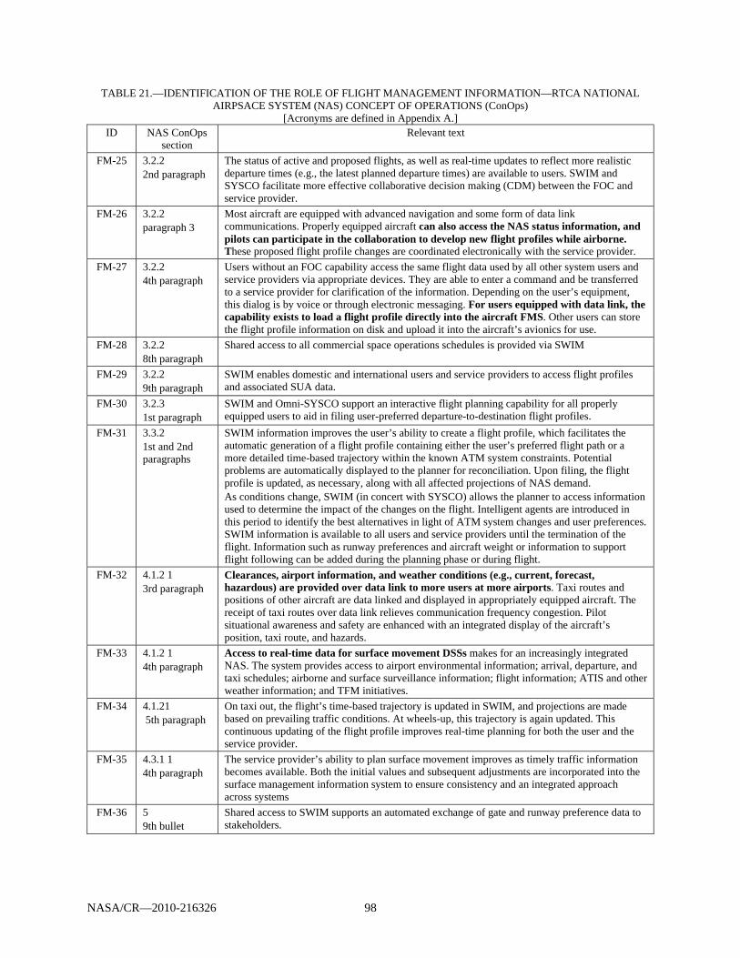
NASA/CR—2010-216326 98
TABLE 21.—IDENTIFICATION OF THE ROLE OF FLIGHT MANAGEMENT INFORMATION—RTCA NATIONAL AIRPSACE SYSTEM (NAS) CONCEPT OF OPERATIONS (ConOps)
[Acronyms are defined in Appendix A.] ID NAS ConOps
section Relevant text
FM-25 3.2.2 2nd paragraph
The status of active and proposed flights, as well as real-time updates to reflect more realistic departure times (e.g., the latest planned departure times) are available to users. SWIM and SYSCO facilitate more effective collaborative decision making (CDM) between the FOC and service provider.
FM-26 3.2.2 paragraph 3
Most aircraft are equipped with advanced navigation and some form of data link communications. Properly equipped aircraft can also access the NAS status information, and pilots can participate in the collaboration to develop new flight profiles while airborne. These proposed flight profile changes are coordinated electronically with the service provider.
FM-27 3.2.2 4th paragraph
Users without an FOC capability access the same flight data used by all other system users and service providers via appropriate devices. They are able to enter a command and be transferred to a service provider for clarification of the information. Depending on the user’s equipment, this dialog is by voice or through electronic messaging. For users equipped with data link, the capability exists to load a flight profile directly into the aircraft FMS. Other users can store the flight profile information on disk and upload it into the aircraft’s avionics for use.
FM-28 3.2.2 8th paragraph
Shared access to all commercial space operations schedules is provided via SWIM
FM-29 3.2.2 9th paragraph
SWIM enables domestic and international users and service providers to access flight profiles and associated SUA data.
FM-30 3.2.3 1st paragraph
SWIM and Omni-SYSCO support an interactive flight planning capability for all properly equipped users to aid in filing user-preferred departure-to-destination flight profiles.
FM-31 3.3.2 1st and 2nd paragraphs
SWIM information improves the user’s ability to create a flight profile, which facilitates the automatic generation of a flight profile containing either the user’s preferred flight path or a more detailed time-based trajectory within the known ATM system constraints. Potential problems are automatically displayed to the planner for reconciliation. Upon filing, the flight profile is updated, as necessary, along with all affected projections of NAS demand. As conditions change, SWIM (in concert with SYSCO) allows the planner to access information used to determine the impact of the changes on the flight. Intelligent agents are introduced in this period to identify the best alternatives in light of ATM system changes and user preferences. SWIM information is available to all users and service providers until the termination of the flight. Information such as runway preferences and aircraft weight or information to support flight following can be added during the planning phase or during flight.
FM-32 4.1.2 1 3rd paragraph
Clearances, airport information, and weather conditions (e.g., current, forecast, hazardous) are provided over data link to more users at more airports. Taxi routes and positions of other aircraft are data linked and displayed in appropriately equipped aircraft. The receipt of taxi routes over data link relieves communication frequency congestion. Pilot situational awareness and safety are enhanced with an integrated display of the aircraft’s position, taxi route, and hazards.
FM-33 4.1.2 1 4th paragraph
Access to real-time data for surface movement DSSs makes for an increasingly integrated NAS. The system provides access to airport environmental information; arrival, departure, and taxi schedules; airborne and surface surveillance information; flight information; ATIS and other weather information; and TFM initiatives.
FM-34 4.1.21 5th paragraph
On taxi out, the flight’s time-based trajectory is updated in SWIM, and projections are made based on prevailing traffic conditions. At wheels-up, this trajectory is again updated. This continuous updating of the flight profile improves real-time planning for both the user and the service provider.
FM-35 4.3.1 1 4th paragraph
The service provider’s ability to plan surface movement improves as timely traffic information becomes available. Both the initial values and subsequent adjustments are incorporated into the surface management information system to ensure consistency and an integrated approach across systems
FM-36 5 9th bullet
Shared access to SWIM supports an automated exchange of gate and runway preference data to stakeholders.

NASA/CR—2010-216326 99
TABLE 21.—IDENTIFICATION OF THE ROLE OF FLIGHT MANAGEMENT INFORMATION—RTCA NATIONAL AIRPSACE SYSTEM (NAS) CONCEPT OF OPERATIONS (ConOps)
[Acronyms are defined in Appendix A.] ID NAS ConOps
section Relevant text
FM-37 5.3.2 6th paragraph
The user’s runway assignment preference is available within SWIM, and is used in conjunction with departure and arrival DSSs and integrated surface management capabilities to coordinate an optimal assignment and sequence.
FM-38 5.3.2 6th paragraph
Data from SWIM allows service providers to monitor traffic demand, NAS infrastructure status, and other conditions in order to allocate resources, including changes in staffing. Service providers also update the NAS about the available capacity of airport and surrounding airspace resources and the current status of SUA. This facilitates more effective collaboration with FOCs and improved formulation of TFM agreements.
FM-39 6.1.2 3rd paragraph
Flights routinely operate on user-preferred trajectories with fewer aircraft constrained to a fixed route structure. The requirement to operate on structured routes only exists in high density areas to avoid terrain and active SUA and to facilitate the transition between areas with differing separation standards. Demand and capacity imbalances are resolved, in collaboration with the users, via voluntary changes in trajectories or through the establishment of temporary routes and transition points. User-preferred trajectories are accommodated earlier in the flight and continue closer to the destination.
FM-40 6.1.2 5th paragraph
The status of active and proposed flights and NAS infrastructure is available to NAS users and service providers. This allows users to collaborate with ATM in deciding TFM initiatives
FM-41 6.2.1 1st paragraph
The FOC monitors the status of the NAS and relays status information to pilots. FOC and aircraft provide preference information, which the service provider considers when making in-flight route changes.
FM-42 6.2.2 1st paragraph
There is increased collaboration between the FOC and ATM as the FOC interactively probes proposed route changes. Modified routes are developed collaboratively between the FOC and the service provider and then data linked to the aircraft and downstream ATC facilities. In addition, working with TFM specialists, the FOC helps to define and implement TFM initiatives to relieve airspace congestion.
TABLE 22.—IDENTIFICATION OF THE ROLE OF AERONAUTICAL INFORMATION—RTCA NATIONAL AIRPSACE
(NAS) CONCEPT OF OPERATIONS (ConOps) ID NAS ConOps
section Relevant text
A-1 1.5.1 1st bullet
Collaboration supports determining when, where, and how transitional route structures are established in the airspace to meet a short-term problem.
A-2 1.5.2 7th bullet
While Required Navigation Performance (RNP)/RNAV capabilities increase, the low-altitude airspace structure remains largely unchanged. Widespread area navigation equipage and expanded surveillance coverage with new technology provide increased access to airports and airspace in all weather conditions.
A-3 1.5.2 8th bullet
There are temporary route structures with transition points for moving to and from user trajectories
A-4 1.5.2 9th bullet
A SWIM system is developed by the service provider to distribute timely and consistent information across the NAS including Static data, such as electronic navigation data, maps, charts, airport facility guides, and published Notices to airmen (NOTAMs) is available directly from the Internet as well as various intranets… Dynamic information, including, but not limited to, current and forecast weather, radar summaries, hazardous condition warnings, information on updated airport and airspace capacity constraints, temporary flight restrictions (TFR), and Special use airspace (SUA) schedules. Flight information Schedule information
A-5 1.5.2 12th bullet
Traffic information collected by surveillance systems is transmitted to properly equipped aircraft to support flight deck decisions.

NASA/CR—2010-216326 100
TABLE 22.—IDENTIFICATION OF THE ROLE OF AERONAUTICAL INFORMATION—RTCA NATIONAL AIRPSACE (NAS) CONCEPT OF OPERATIONS (ConOps)
ID NAS ConOps section
Relevant text
A-6 1.5.2 14th bullet
The ATM system manages airspace based on each user's needs, including proximity to the user’s base of operations.
A-7 1.5.2 17th bullet
Tools and procedures are in place for frequent evaluation (up to several times a day) of the airspace structure and anticipated traffic flows, with adjustments made accordingly.
A-8 1.5.3 2nd bullet
Enhanced CNS systems and automation in aircraft complement automation aids on the ground, permitting more autonomous operations. This improved autonomy, combined with greater ability to share information, permits the workload to be distributed between the service provider and user in a balance appropriate for the operations being conducted.
A-9 1.5.3 4th bullet
Seamless communications and coordination, coupled with information accessible through SWIM, allow real-time reassignment of airspace between facilities to meet contingencies such as equipment outages.
A-10 2.1.3 2nd paragraph
Flow-constrained areas are managed by allocating access, collaborative rerouting, and realigning sectors and associated resources.
A-11 2.2.1 1st paragraph
Users have access to an increasing amount of NAS information including airport status and acceptance rate, …
A-12 2.2.1 3rd paragraph
Working with the service providers, users better manage en route congestion by collaboratively evaluating the situations, developing re-routes around the flow constrained areas, and providing a more refined allocation of flights to the reroutes.
A-13 2.3.2 3rd paragraph
Information about arrival capacity allocations, reroute programs and other restrictions is automatically recorded, as is information from local facilities….
A-14 3 1st bullet
Elements of SWM are used to obtain and distribute flight-specific data and aeronautical information, including international coordination of flight trajectory.
A-15 3.1.1 3rd paragraph
There is real time sharing of system demand and the virtual ATM information… User flight planning systems account for system constraints such as flow restrictions, hazardous weather, SUA and infrastructure outages.
A-16 3.1.2 1st paragraph
A National Airspace System common reference (NASCR) and index that incorporates a common Geographical Information System (GIS) format is used to store all NAS information including terrain, obstacle, weather, and navigation, surveillance and communication coverage information. This information is available via SWIM to all service providers and users.
A-17 3.1.2 3rd paragraph
To generate the flight profile, users access current and predicted weather, traffic density, restrictions, and SUA status information.
A-18 3.2.2 7th paragraph
DoD and FAA service providers maintain and have access to a continuously updated database of airspace and flow restrictions. Using this data, the DoD flight planner prepares a proposed flight profile, performing a probe for active or scheduled SUAs, weather, and airspace and flow restrictions.
A-19 3.2.2 9th paragraph
Space vehicle flight profiles describe user needs and take into account flow conditions and constraints. SWIM enables domestic and international users and service providers to access flight profiles and associated SUA data.
A-20 41 6th bullet
Airport layouts on moving maps and corresponding standardized airport signage provide flight crews with increased situation awareness and reduce runway incursions.
A-21 4.1.21 1st paragraph
Moving map displays enhance pilot familiarity with the airport, leading to better planning and increased safety.
A-22 4.1.21 4th paragraph
Access to real-time data for surface movement DSSs makes for an increasingly integrated NAS. The surface management information system facilitates coordination between decision makers at all levels of the airport operation—service provider, flight crews, FOC, ramp, airport operator, and airport emergency centers. The system provides access to airport environmental information; arrival, departure, and taxi schedules; airborne and surface surveillance information; flight information; ATIS and other weather information; and TFM initiatives. This data sharing allows service providers to coordinate local operations with airline ramp and airport operators, thus improving overall airport operations.
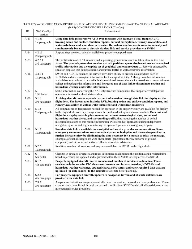
NASA/CR—2010-216326 101
TABLE 22.—IDENTIFICATION OF THE ROLE OF AERONAUTICAL INFORMATION—RTCA NATIONAL AIRPSACE (NAS) CONCEPT OF OPERATIONS (ConOps)
ID NAS ConOps section
Relevant text
A-23 4.1.31 1st paragraph
Using data link, pilots receive ATIS-type messages with Runway Visual Range (RVR), braking action and surface condition reports, current precipitation, runway availability, and wake turbulence and wind shear advisories. Hazardous weather alerts are automatically and simultaneously broadcast to aircraft via data link and service providers via SWIM.
A-24 4.2.11 2nd paragraph
Airport maps are electronically available to properly equipped users
A-25 4.2.2 1 3rd paragraph
The proliferation of CDTI avionics and supporting ground infrastructure takes place in this time frame. The ground system that receives aircraft position reports also broadcasts radar-derived traffic information and a complete set of graphical and text products … Safety is enhanced by situation displays that depict airborne and surface traffic as well aerodrome information.
A-26 4.3.1 1 1st paragraph
SWIM and ACARS enhance the service provider’s ability to provide data products such as NOTAMs and meteorological information for the airport vicinity. Although weather information and advisories continue to be available via traditional means, there is increased use of automation to collect and package the information and increased use of data link to disseminate routine and hazardous weather and traffic information.
A-27 5 10th bullet
Status information concerning the NAS infrastructure components that support arrival/departure operations is shared with all stakeholders.
A-28 5.1.1 3rd paragraph
Arriving aircraft receive expanded airport information through data link for display on the flight deck. The information includes RVR, braking action and surface condition reports, and runway availability as well as wake turbulence and wind shear advisories
A-29 5.1.2 2nd paragraph
All communication frequencies needed for operation in the airport vicinity are available for display to the flight deck, with any changes from the published list uplinked over data link. Data link and flight deck displays enable pilots to monitor current meteorological data, automated hazardous weather alerts, and surrounding traffic, thus reducing the number of verbal miscommunications of this routine information. Pilots conduct approaches using independent navigation systems and begin monitoring the approach path on a moving map display.
A-30 5.1.3 1st paragraph
Seamless data link is available for most pilot and service provider communications. Some emergency communications are automatically sent to both pilot and the service provider to further increase safety by eliminating the time necessary for a human to relay the message. Examples of such messages are wind shear alerts (generated either by airborne or ground equipment) and airborne and surface collision resolution advisories.
A-31 5.2.2 1st paragraph
Real time weather information and maps are available via SWIM on the flight deck.
A-32 6 5th bullet
Changes in airspace structures and route definitions in addition to the positions and predicted time-based trajectories are updated and registered within the NASCR for easy access via SWIM.
A-33 6.1.2 4th paragraph
Properly equipped aircraft receive an increased number of services via data link. These services includes certain ATC clearances, current and forecast weather, NOTAMs and hazardous weather warnings, updated charts, SUA status, and other required data that are up-linked (or data-loaded) to the aircraft to facilitate better planning.
A-34 6.2.2 4th paragraph
For properly-equipped aircraft, updates to navigation terrain and obstacle databases are provided over data link.
A-35 7.3.3 3rd paragraph
Airspace sectorization changes dynamically based on weather, demand, and user preferences. These changes are accomplished through automated coordination (SYSCO) with all affected domestic and international service providers.
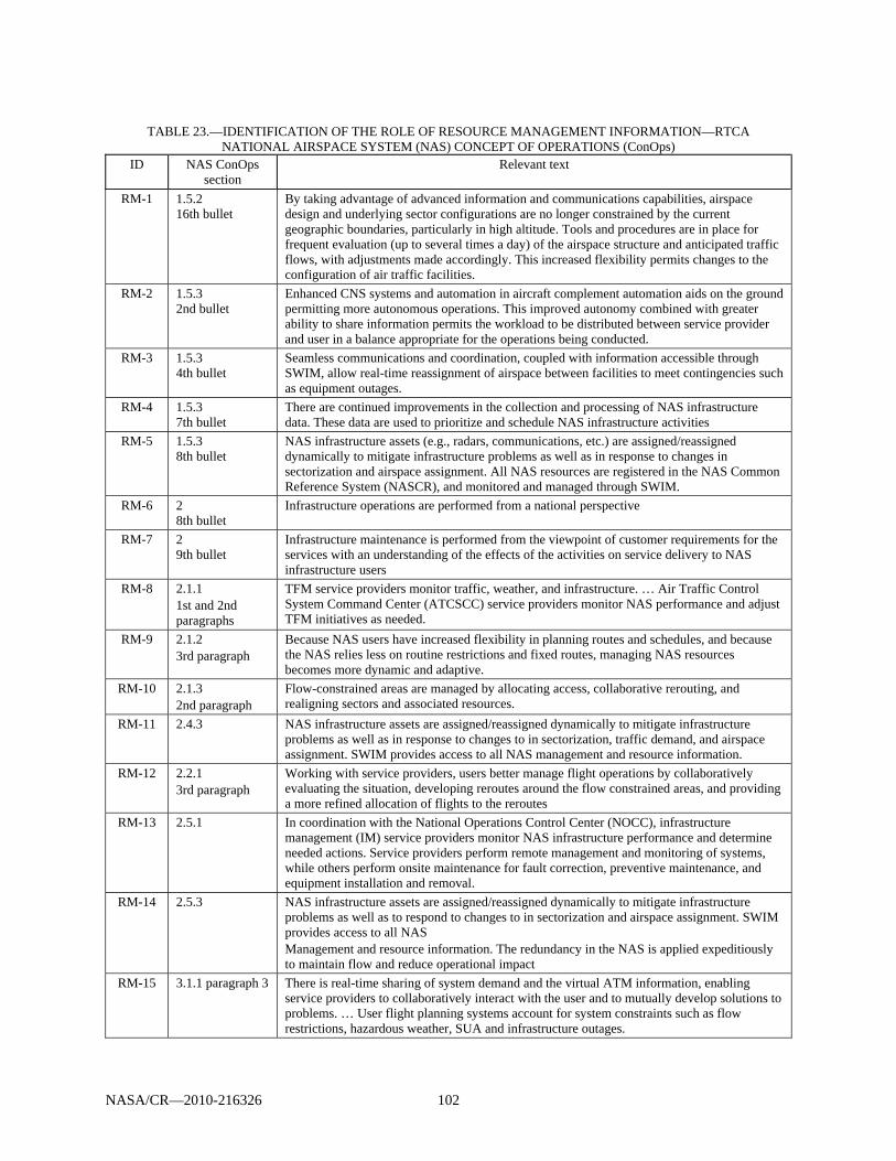
NASA/CR—2010-216326 102
TABLE 23.—IDENTIFICATION OF THE ROLE OF RESOURCE MANAGEMENT INFORMATION—RTCA
NATIONAL AIRSPACE SYSTEM (NAS) CONCEPT OF OPERATIONS (ConOps) ID NAS ConOps
section Relevant text
RM-1 1.5.2 16th bullet
By taking advantage of advanced information and communications capabilities, airspace design and underlying sector configurations are no longer constrained by the current geographic boundaries, particularly in high altitude. Tools and procedures are in place for frequent evaluation (up to several times a day) of the airspace structure and anticipated traffic flows, with adjustments made accordingly. This increased flexibility permits changes to the configuration of air traffic facilities.
RM-2 1.5.3 2nd bullet
Enhanced CNS systems and automation in aircraft complement automation aids on the ground permitting more autonomous operations. This improved autonomy combined with greater ability to share information permits the workload to be distributed between service provider and user in a balance appropriate for the operations being conducted.
RM-3 1.5.3 4th bullet
Seamless communications and coordination, coupled with information accessible through SWIM, allow real-time reassignment of airspace between facilities to meet contingencies such as equipment outages.
RM-4 1.5.3 7th bullet
There are continued improvements in the collection and processing of NAS infrastructure data. These data are used to prioritize and schedule NAS infrastructure activities
RM-5 1.5.3 8th bullet
NAS infrastructure assets (e.g., radars, communications, etc.) are assigned/reassigned dynamically to mitigate infrastructure problems as well as in response to changes in sectorization and airspace assignment. All NAS resources are registered in the NAS Common Reference System (NASCR), and monitored and managed through SWIM.
RM-6 2 8th bullet
Infrastructure operations are performed from a national perspective
RM-7 2 9th bullet
Infrastructure maintenance is performed from the viewpoint of customer requirements for the services with an understanding of the effects of the activities on service delivery to NAS infrastructure users
RM-8 2.1.1 1st and 2nd paragraphs
TFM service providers monitor traffic, weather, and infrastructure. … Air Traffic Control System Command Center (ATCSCC) service providers monitor NAS performance and adjust TFM initiatives as needed.
RM-9 2.1.2 3rd paragraph
Because NAS users have increased flexibility in planning routes and schedules, and because the NAS relies less on routine restrictions and fixed routes, managing NAS resources becomes more dynamic and adaptive.
RM-10 2.1.3 2nd paragraph
Flow-constrained areas are managed by allocating access, collaborative rerouting, and realigning sectors and associated resources.
RM-11 2.4.3 NAS infrastructure assets are assigned/reassigned dynamically to mitigate infrastructure problems as well as in response to changes to in sectorization, traffic demand, and airspace assignment. SWIM provides access to all NAS management and resource information.
RM-12 2.2.1 3rd paragraph
Working with service providers, users better manage flight operations by collaboratively evaluating the situation, developing reroutes around the flow constrained areas, and providing a more refined allocation of flights to the reroutes
RM-13 2.5.1 In coordination with the National Operations Control Center (NOCC), infrastructure management (IM) service providers monitor NAS infrastructure performance and determine needed actions. Service providers perform remote management and monitoring of systems, while others perform onsite maintenance for fault correction, preventive maintenance, and equipment installation and removal.
RM-14 2.5.3 NAS infrastructure assets are assigned/reassigned dynamically to mitigate infrastructure problems as well as to respond to changes to in sectorization and airspace assignment. SWIM provides access to all NAS Management and resource information. The redundancy in the NAS is applied expeditiously to maintain flow and reduce operational impact
RM-15 3.1.1 paragraph 3 There is real-time sharing of system demand and the virtual ATM information, enabling service providers to collaboratively interact with the user and to mutually develop solutions to problems. … User flight planning systems account for system constraints such as flow restrictions, hazardous weather, SUA and infrastructure outages.
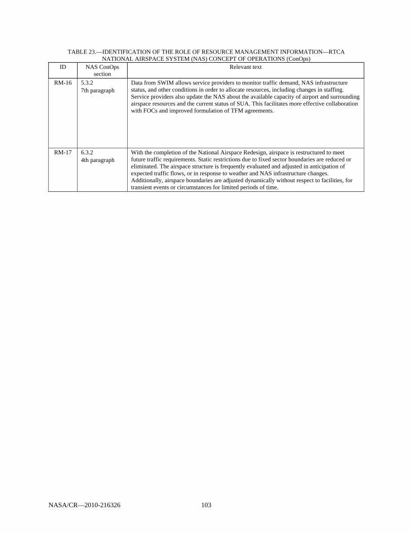
NASA/CR—2010-216326 103
TABLE 23.—IDENTIFICATION OF THE ROLE OF RESOURCE MANAGEMENT INFORMATION—RTCA NATIONAL AIRSPACE SYSTEM (NAS) CONCEPT OF OPERATIONS (ConOps)
ID NAS ConOps section
Relevant text
RM-16 5.3.2 7th paragraph
Data from SWIM allows service providers to monitor traffic demand, NAS infrastructure status, and other conditions in order to allocate resources, including changes in staffing. Service providers also update the NAS about the available capacity of airport and surrounding airspace resources and the current status of SUA. This facilitates more effective collaboration with FOCs and improved formulation of TFM agreements.
RM-17 6.3.2 4th paragraph
With the completion of the National Airspace Redesign, airspace is restructured to meet future traffic requirements. Static restrictions due to fixed sector boundaries are reduced or eliminated. The airspace structure is frequently evaluated and adjusted in anticipation of expected traffic flows, or in response to weather and NAS infrastructure changes. Additionally, airspace boundaries are adjusted dynamically without respect to facilities, for transient events or circumstances for limited periods of time.


NASA/CR—2010-216326 105
Appendix C.—Hierarchical Diagrams of Functional Requirements
This appendix contains the functional analysis of the L-band communication system presented as a series of hierarchical diagrams. The “L” preceding all of the numerical functional levels is used to represent L-band.”
The analysis and diagrams are adopted from the National Airspace System (NAS) Communications System Safety Hazard Analysis and Security Threat Analysis document (Ref. 54).
Solid blocks in the diagrams represent system functions that are part of the L-band system scope assumptions; background blocks show NAS functions that are currently not part of the L-band functionality.
Figure 38.—L-band communications system high level.
Figure 39.—Decomposition of use L-band communications system (transmit/receive messages).
L.1.1.4Transceive
Fixed to Fixed Message
L.1.1 Use L‐Band Communications System
L.1 Provide ATC Communications over L‐Band Communications System
L.1.2 Operate L‐Band Communications System
L.1.1.1 Transceive Fixed to Mobile Message
L.1.1.3Transceive
Mobile to MobileMessage
L. 1.2.2 Maintain L‐Band Communications
System
L. 1.2.3 Configure L‐Band Communications
System
L. 1.2.1 Monitor L‐Band Communications
System
L.1.1.2Transceive Mobile to Fixed
Message
L.1.1 Use L‐Band Communications System
(Transmit/Receive Messages)
L.1.1.1.1 Transceive Fixed to Airborne Mobile Message
L.1.1.2.1Transceive Airborne Mobile to Fixed
Message
L.1.1.1.2 Transceive Fixed to
On‐ground Mobile Message
L.1.1.1 Transceive Fixed to Mobile Message
L.1.1.3Transceive
Mobile to MobileMessage
L.1.1.2Transceive Mobile to Fixed
Message
L.1.1.4Transceive
Fixed to Fixed Message
L.1.1.2.2Transceive On‐ground Mobile to Fixed
Message
L.1.1.3.1 Transceive Airborne Mobile to Airborne Mobile Message
L.1.1.3.3Transceive On‐ground Mobile to Airborne Mobile Message
L.1.1.3.2 Transceive Airborne Mobile to On‐ground Mobile Message
L.1.1.3.4Transceive On‐ground Mobile to On‐ground Mobile Message

NASA/CR—2010-216326 106
Figure 40.—Decomposition of transceive fixed-to-mobile message.
L.1.1.1.1.1 Transceive
Fixed to Airborne Aircraft Message
L.1.1.1.1.1.1Transceive Fixed to Airborne
Aircraft Voice Message
L.1.1.1.1.1.2Transceive Fixed to Airborne
Aircraft Data Message
L.1.1.1.2 .1Transceive
Fixed to On‐ground Aircraft Message
L.1.1.1.2 .2Transceive
Fixed to On‐ground Vehicles Message
L.1.1.1.1 Transceive Fixed to Airborne Mobile Message
L.1.1.1.2 Transceive Fixed to
On‐ground Mobile Message
L.1.1.1.2.1.1Transceive Fixed to On‐
ground Aircraft Voice Message
L.1.1.1.2.1.2Transceive Fixed to On‐
ground Aircraft Data Message
L.1.1.1 Transceive Fixed to Mobile Message

NASA/CR—2010-216326 107
Figure 41.—Decomposition of transceive mobile-to-fixed message.
L.1.1.2.1.1 Transceive Airborne Aircraft to
Fixed Message
L.1.1.2.1.1 .1 Transceive Airborne Aircraft to Fixed Voice Message
L.1.1.2.1.1.2 Transceive Airborne Aircraft to Fixed Data Message
L.1.1.2.2 .1Transceive On‐ground Aircraft to Fixed
Message
L.1.1.1.2 .2Transceive
On‐ground Vehicle to Fixed Message
L.1.1.2.2 .1.1Transceive On‐ground Aircraft to Fixed Voice Message
L.1.1.2.2 .1.2Transceive On‐ground Aircraft to Fixed Data Message
L.1.1.2Transceive Mobile to Fixed
Message
L.1.1.2.1Transceive Airborne Mobile to Fixed
Message
L.1.1.2.2Transceive On‐ground Mobile to Fixed
Message
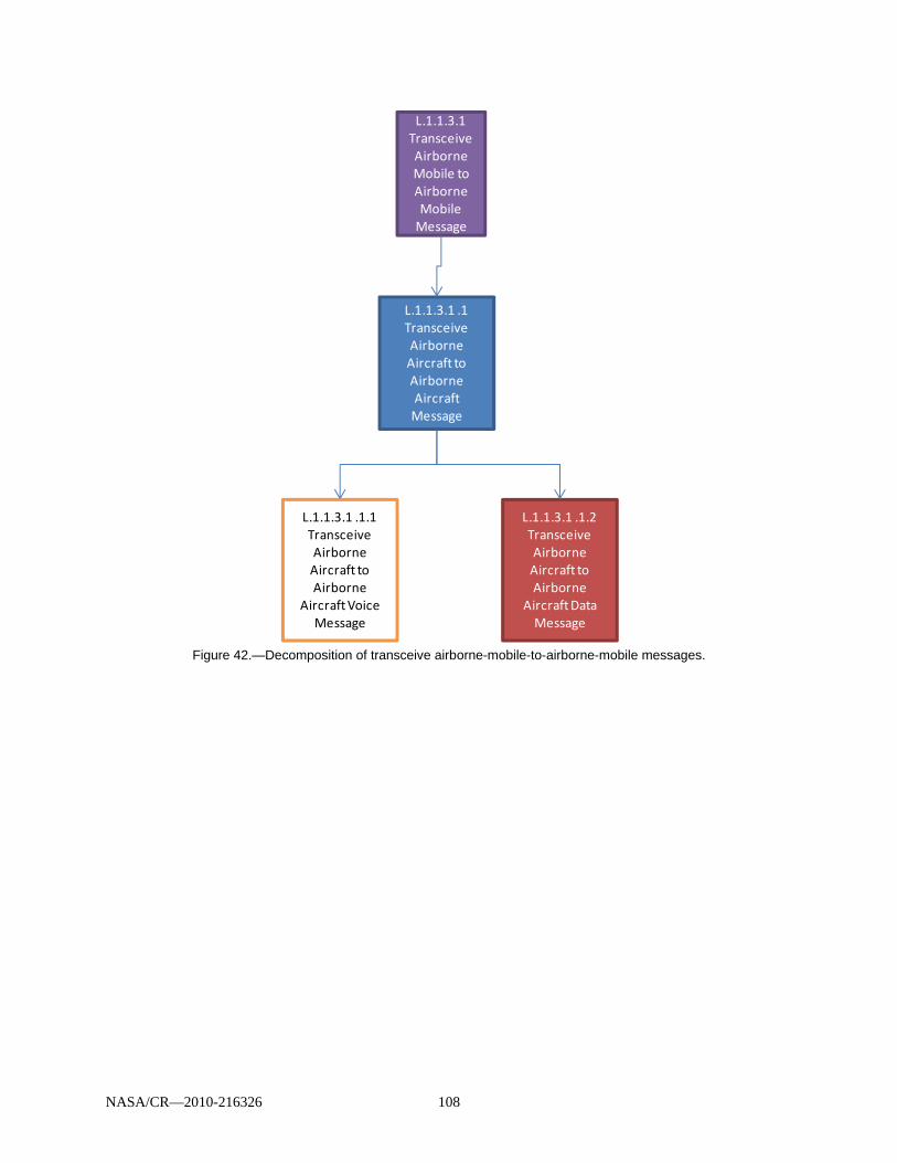
NASA/CR—2010-216326 108
Figure 42.—Decomposition of transceive airborne-mobile-to-airborne-mobile messages.
L.1.1.3.1 Transceive Airborne Mobile to Airborne Mobile Message
L.1.1.3.1 .1 Transceive Airborne Aircraft to Airborne Aircraft Message
L.1.1.3.1 .1.1 Transceive Airborne Aircraft to Airborne
Aircraft Voice Message
L.1.1.3.1 .1.2 Transceive Airborne Aircraft to Airborne
Aircraft Data Message
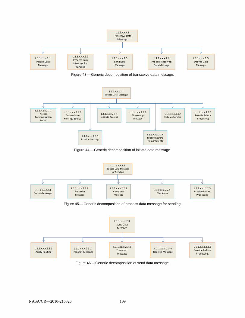
NASA/CR—2010-216326 109
Figure 43.—Generic decomposition of transceive data message.
Figure 44.—Generic decomposition of initiate data message.
Figure 45.—Generic decomposition of process data message for sending.
Figure 46.—Generic decomposition of send data message.
L.1.1.x.x.x.2.1Initiate Data Message
L.1.1.x.x.x.2.2Process Data Message for Sending
L.1.1.x.x.x.2.3Send Data Message
L.1.1.x.x.x.2Transceive Data
Message
L.1.1.x.x.x.2.5Deliver Data Message
L.1.1.x.x.x.2.4Process Received Data Message
L.1.1.x.x.x.2.1Initiate Data Message
L.1.1.x.x.x.2.1.1Access
Communication System
L.1.1.x.x.x.2.1.2Authenticate
Message Source
L.1.1.x.x.x.2.1.3Provide Message
L.1.1.x.x.x.2.1.4Indicate Receipt
L.1.1.x.x.x.2.1.5Timestamp Message
L.1.1.x.x.x.2.1.6Specify Routing Requirements
L.1.1.x.x.x.2.1.7Indicate Sender
L.1.1.x.x.x.2.1.8Provide Failure Processing
L.1.1.x.x.x.2.2Process Data Message
for Sending
L.1.1.x.x.x.2.2.1Encode Message
L.1.1. x.x.x.2.2.2Packetize Message
L.1.1.x.x.x.2.2.3Compress Message
L.1.1.x.x.x.2.2.4Checksum
L.1.1.x.x.x.2.2.5Provide Failure Processing
L.1.1.x.x.x.2.3.1Apply Routing
L.1.1.x.x.x.2.3.2Transmit Message
L.1.1.x.x.x.2.3.5Provide FailureProcessing
L.1.1.x.x.x.2.3Send Data Message
L.1.1.x.x.x.2.3.4Receive Message
L.1.1.x.x.x.2.3.3Transport Message
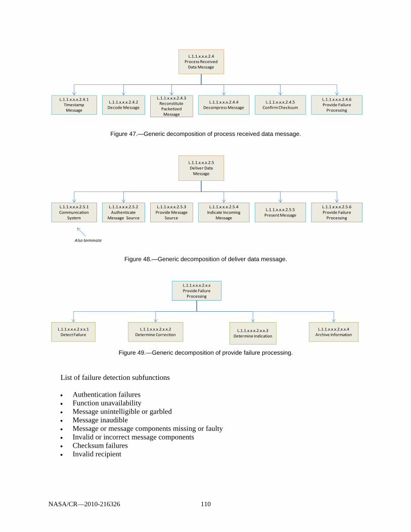
NASA/CR—2010-216326 110
Figure 47.—Generic decomposition of process received data message.
Figure 48.—Generic decomposition of deliver data message.
Figure 49.—Generic decomposition of provide failure processing.
List of failure detection subfunctions Authentication failures Function unavailability Message unintelligible or garbled Message inaudible Message or message components missing or faulty Invalid or incorrect message components Checksum failures Invalid recipient
L.1.1.x.x.x.2.4.1Timestamp Message
L.1.1.x.x.x.2.4.2Decode Message
L.1.1.x.x.x.2.4.3Reconstitute Packetized Message
L.1.1.x.x.x.2.4.4Decompress Message
L.1.1.x.x.x.2.4.5Confirm Checksum
L.1.1.x.x.x.2.4.6Provide Failure Processing
L.1.1.x.x.x.2.4Process Received Data Message
L.1.1.x.x.x.2.5.1Communication
System
L.1.1.x.x.x.2.5.2Authenticate
Message Source
L.1.1.x.x.x.2.5.4Indicate Incoming
Message
L.1.1.x.x.x.2.5.5Present Message
L.1.1.x.x.x.2.5.6Provide Failure Processing
L.1.1.x.x.x.2.5.3Provide Message
Source
Also terminate
L.1.1.x.x.x.2.5Deliver Data Message
L.1.1.x.x.x.2.x.xProvide Failure Processing
L.1.1.x.x.x.2.x.x.1Detect Failure
L.1.1.x.x.x.2.x.x.2Determine Correction
L.1.1.x.x.x.2.x.x.3Determine Indication
L.1.1.x.x.x.2.x.x.4Archive Information

NASA/CR—2010-216326 111
Figure 50.—Decomposition of operate L-band communications system.
Figure 51.—Decomposition of monitor L-band communications system.
L.1.2 Operate L‐Band Communications System
L. 1.2.2 Maintain L‐Band Communications
System
L. 1.2.3 Configure L‐Band Communications
System
L. 1.2.1 Monitor L‐Band Communications
System
L. 1.2.1 Monitor L‐Band Communications
System
L. 1.2.1.2 Indicate Status
L. 1.2.1.3 Verify
Performance
L. 1.2.1 .1Determine Status
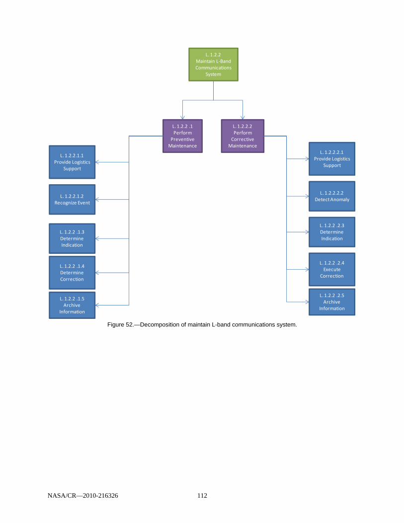
NASA/CR—2010-216326 112
Figure 52.—Decomposition of maintain L-band communications system.
L. 1.2.2 Maintain L‐Band Communications
System
L. 1.2.2.2 Perform Corrective
Maintenance
L. 1.2.2 .1Perform
Preventive Maintenance
L. 1.2.2 .1.4Determine Correction
L. 1.2.2 .1.3Determine Indication
L. 1.2.2.1.2 Recognize Event
L. 1.2.2.1.1Provide Logistics
Support
L. 1.2.2 .1.5Archive
Information
L. 1.2.2 .2.4Execute
Correction
L. 1.2.2 .2.3Determine Indication
L. 1.2.2.2.2 Detect Anomaly
L. 1.2.2.2.1Provide Logistics
Support
L. 1.2.2 .2.5Archive
Information
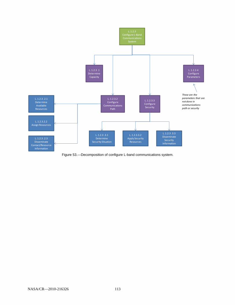
NASA/CR—2010-216326 113
Figure 53.—Decomposition of configure L-band communications system.
L. 1.2.3 .1Determine Capacity
L. 1.2.3 Configure L‐Band Communications
System
L. 1.2.3.2 Configure
Communications Path
L. 1.2.3.3 Configure Security
L. 1.2.3 4Configure Parameters
These are the parameters that are not done in communications path or security
L. 1.2.3 .2.3Disseminate
Contact/Resource Information
L. 1.2.3.2.2 Assign Resources
L. 1.2.3 .2.1Determine Available Resources
L. 1.2.3 .3.3Disseminate Security
Information
L. 1.2.3.3.2 Apply Security Resources
L. 1.2.3 .3.1Determine
Security Situation
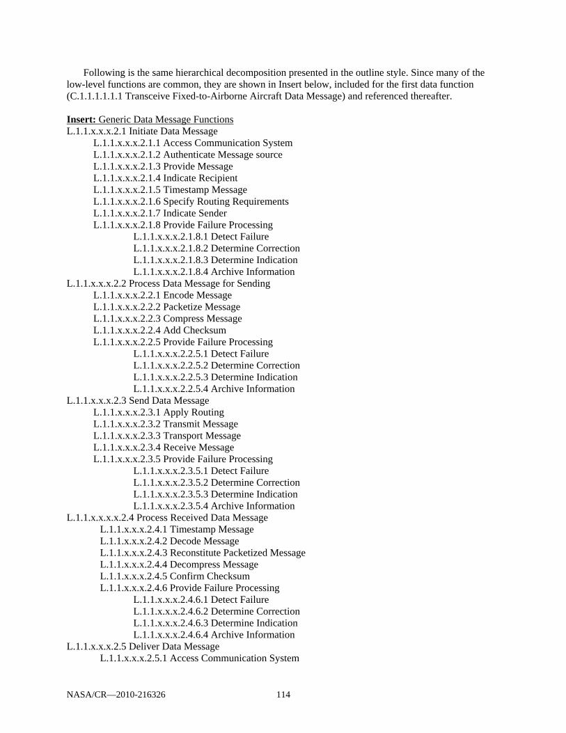
NASA/CR—2010-216326 114
Following is the same hierarchical decomposition presented in the outline style. Since many of the low-level functions are common, they are shown in Insert below, included for the first data function (C.1.1.1.1.1.1 Transceive Fixed-to-Airborne Aircraft Data Message) and referenced thereafter. Insert: Generic Data Message Functions L.1.1.x.x.x.2.1 Initiate Data Message
L.1.1.x.x.x.2.1.1 Access Communication System L.1.1.x.x.x.2.1.2 Authenticate Message source L.1.1.x.x.x.2.1.3 Provide Message L.1.1.x.x.x.2.1.4 Indicate Recipient L.1.1.x.x.x.2.1.5 Timestamp Message L.1.1.x.x.x.2.1.6 Specify Routing Requirements L.1.1.x.x.x.2.1.7 Indicate Sender L.1.1.x.x.x.2.1.8 Provide Failure Processing
L.1.1.x.x.x.2.1.8.1 Detect Failure L.1.1.x.x.x.2.1.8.2 Determine Correction L.1.1.x.x.x.2.1.8.3 Determine Indication L.1.1.x.x.x.2.1.8.4 Archive Information
L.1.1.x.x.x.2.2 Process Data Message for Sending L.1.1.x.x.x.2.2.1 Encode Message L.1.1.x.x.x.2.2.2 Packetize Message L.1.1.x.x.x.2.2.3 Compress Message L.1.1.x.x.x.2.2.4 Add Checksum L.1.1.x.x.x.2.2.5 Provide Failure Processing
L.1.1.x.x.x.2.2.5.1 Detect Failure L.1.1.x.x.x.2.2.5.2 Determine Correction L.1.1.x.x.x.2.2.5.3 Determine Indication L.1.1.x.x.x.2.2.5.4 Archive Information
L.1.1.x.x.x.2.3 Send Data Message L.1.1.x.x.x.2.3.1 Apply Routing L.1.1.x.x.x.2.3.2 Transmit Message L.1.1.x.x.x.2.3.3 Transport Message L.1.1.x.x.x.2.3.4 Receive Message L.1.1.x.x.x.2.3.5 Provide Failure Processing
L.1.1.x.x.x.2.3.5.1 Detect Failure L.1.1.x.x.x.2.3.5.2 Determine Correction L.1.1.x.x.x.2.3.5.3 Determine Indication L.1.1.x.x.x.2.3.5.4 Archive Information
L.1.1.x.x.x.x.2.4 Process Received Data Message L.1.1.x.x.x.2.4.1 Timestamp Message L.1.1.x.x.x.2.4.2 Decode Message L.1.1.x.x.x.2.4.3 Reconstitute Packetized Message L.1.1.x.x.x.2.4.4 Decompress Message L.1.1.x.x.x.2.4.5 Confirm Checksum L.1.1.x.x.x.2.4.6 Provide Failure Processing
L.1.1.x.x.x.2.4.6.1 Detect Failure L.1.1.x.x.x.2.4.6.2 Determine Correction L.1.1.x.x.x.2.4.6.3 Determine Indication L.1.1.x.x.x.2.4.6.4 Archive Information
L.1.1.x.x.x.2.5 Deliver Data Message L.1.1.x.x.x.2.5.1 Access Communication System
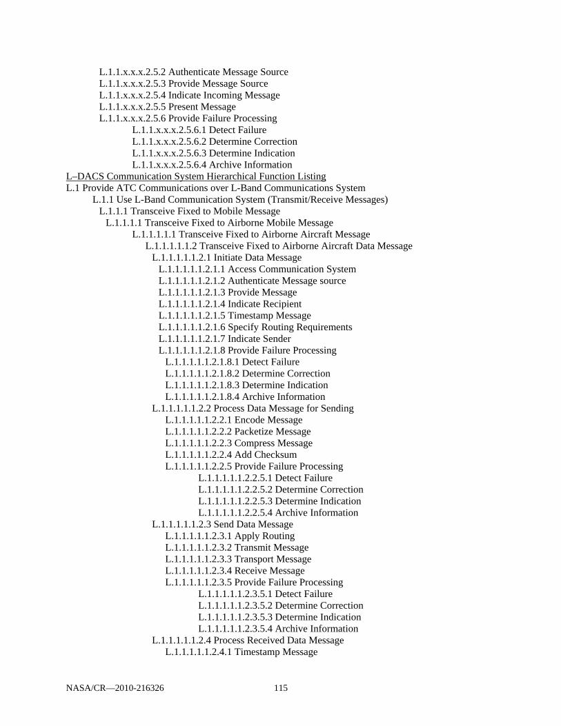
NASA/CR—2010-216326 115
L.1.1.x.x.x.2.5.2 Authenticate Message Source L.1.1.x.x.x.2.5.3 Provide Message Source L.1.1.x.x.x.2.5.4 Indicate Incoming Message L.1.1.x.x.x.2.5.5 Present Message L.1.1.x.x.x.2.5.6 Provide Failure Processing
L.1.1.x.x.x.2.5.6.1 Detect Failure L.1.1.x.x.x.2.5.6.2 Determine Correction L.1.1.x.x.x.2.5.6.3 Determine Indication L.1.1.x.x.x.2.5.6.4 Archive Information
L–DACS Communication System Hierarchical Function Listing L.1 Provide ATC Communications over L-Band Communications System
L.1.1 Use L-Band Communication System (Transmit/Receive Messages) L.1.1.1 Transceive Fixed to Mobile Message
L.1.1.1.1 Transceive Fixed to Airborne Mobile Message L.1.1.1.1.1 Transceive Fixed to Airborne Aircraft Message L.1.1.1.1.1.2 Transceive Fixed to Airborne Aircraft Data Message
L.1.1.1.1.1.2.1 Initiate Data Message L.1.1.1.1.1.2.1.1 Access Communication System L.1.1.1.1.1.2.1.2 Authenticate Message source L.1.1.1.1.1.2.1.3 Provide Message L.1.1.1.1.1.2.1.4 Indicate Recipient L.1.1.1.1.1.2.1.5 Timestamp Message L.1.1.1.1.1.2.1.6 Specify Routing Requirements L.1.1.1.1.1.2.1.7 Indicate Sender L.1.1.1.1.1.2.1.8 Provide Failure Processing
L.1.1.1.1.1.2.1.8.1 Detect Failure L.1.1.1.1.1.2.1.8.2 Determine Correction L.1.1.1.1.1.2.1.8.3 Determine Indication L.1.1.1.1.1.2.1.8.4 Archive Information
L.1.1.1.1.1.2.2 Process Data Message for Sending L.1.1.1.1.1.2.2.1 Encode Message L.1.1.1.1.1.2.2.2 Packetize Message L.1.1.1.1.1.2.2.3 Compress Message L.1.1.1.1.1.2.2.4 Add Checksum L.1.1.1.1.1.2.2.5 Provide Failure Processing
L.1.1.1.1.1.2.2.5.1 Detect Failure L.1.1.1.1.1.2.2.5.2 Determine Correction L.1.1.1.1.1.2.2.5.3 Determine Indication L.1.1.1.1.1.2.2.5.4 Archive Information
L.1.1.1.1.1.2.3 Send Data Message L.1.1.1.1.1.2.3.1 Apply Routing L.1.1.1.1.1.2.3.2 Transmit Message L.1.1.1.1.1.2.3.3 Transport Message L.1.1.1.1.1.2.3.4 Receive Message L.1.1.1.1.1.2.3.5 Provide Failure Processing
L.1.1.1.1.1.2.3.5.1 Detect Failure L.1.1.1.1.1.2.3.5.2 Determine Correction L.1.1.1.1.1.2.3.5.3 Determine Indication L.1.1.1.1.1.2.3.5.4 Archive Information
L.1.1.1.1.1.2.4 Process Received Data Message L.1.1.1.1.1.2.4.1 Timestamp Message
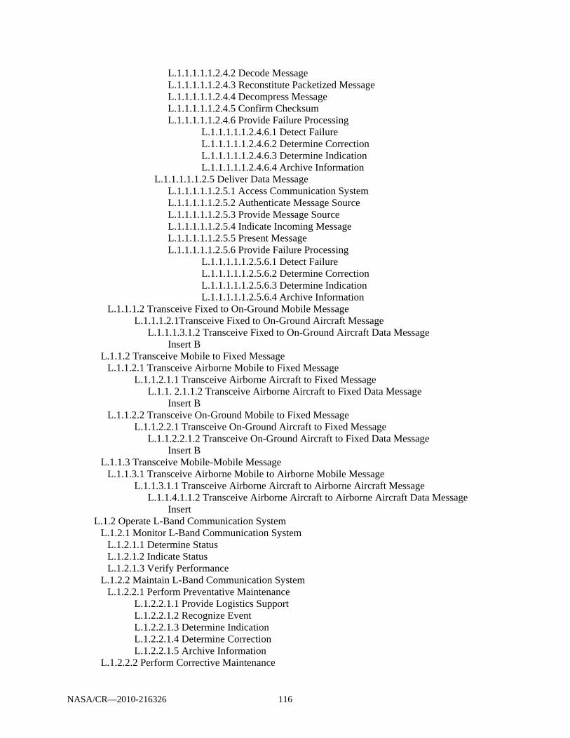
NASA/CR—2010-216326 116
L.1.1.1.1.1.2.4.2 Decode Message L.1.1.1.1.1.2.4.3 Reconstitute Packetized Message L.1.1.1.1.1.2.4.4 Decompress Message L.1.1.1.1.1.2.4.5 Confirm Checksum L.1.1.1.1.1.2.4.6 Provide Failure Processing
L.1.1.1.1.1.2.4.6.1 Detect Failure L.1.1.1.1.1.2.4.6.2 Determine Correction L.1.1.1.1.1.2.4.6.3 Determine Indication L.1.1.1.1.1.2.4.6.4 Archive Information
L.1.1.1.1.1.2.5 Deliver Data Message L.1.1.1.1.1.2.5.1 Access Communication System L.1.1.1.1.1.2.5.2 Authenticate Message Source L.1.1.1.1.1.2.5.3 Provide Message Source L.1.1.1.1.1.2.5.4 Indicate Incoming Message L.1.1.1.1.1.2.5.5 Present Message L.1.1.1.1.1.2.5.6 Provide Failure Processing
L.1.1.1.1.1.2.5.6.1 Detect Failure L.1.1.1.1.1.2.5.6.2 Determine Correction L.1.1.1.1.1.2.5.6.3 Determine Indication L.1.1.1.1.1.2.5.6.4 Archive Information
L.1.1.1.2 Transceive Fixed to On-Ground Mobile Message L.1.1.1.2.1Transceive Fixed to On-Ground Aircraft Message L.1.1.1.3.1.2 Transceive Fixed to On-Ground Aircraft Data Message Insert B
L.1.1.2 Transceive Mobile to Fixed Message L.1.1.2.1 Transceive Airborne Mobile to Fixed Message L.1.1.2.1.1 Transceive Airborne Aircraft to Fixed Message L.1.1. 2.1.1.2 Transceive Airborne Aircraft to Fixed Data Message
Insert B L.1.1.2.2 Transceive On-Ground Mobile to Fixed Message L.1.1.2.2.1 Transceive On-Ground Aircraft to Fixed Message L.1.1.2.2.1.2 Transceive On-Ground Aircraft to Fixed Data Message Insert B
L.1.1.3 Transceive Mobile-Mobile Message L.1.1.3.1 Transceive Airborne Mobile to Airborne Mobile Message L.1.1.3.1.1 Transceive Airborne Aircraft to Airborne Aircraft Message L.1.1.4.1.1.2 Transceive Airborne Aircraft to Airborne Aircraft Data Message Insert
L.1.2 Operate L-Band Communication System L.1.2.1 Monitor L-Band Communication System
L.1.2.1.1 Determine Status L.1.2.1.2 Indicate Status L.1.2.1.3 Verify Performance
L.1.2.2 Maintain L-Band Communication System L.1.2.2.1 Perform Preventative Maintenance
L.1.2.2.1.1 Provide Logistics Support L.1.2.2.1.2 Recognize Event L.1.2.2.1.3 Determine Indication L.1.2.2.1.4 Determine Correction L.1.2.2.1.5 Archive Information
L.1.2.2.2 Perform Corrective Maintenance

NASA/CR—2010-216326 117
L.1.2.2.2.1 Provide Logistics Support L.1.2.2.2.2 Detect Anomaly L.1.2.2.2.3 Determine Indication L.1.2.2.2.4 Execute Correction L.1.2.2.2.5 Archive Information
L.1.2.3 Configure L-Band Communication System L.1.2.3.1 Determine Capacity L.1.2.3.2 Configure Communication Path
L.1.2.3.2.1 Determine Available Resources L.1.2.3.2.2 Assign Resources L.1.2.3.2.3 Disseminate Contact/Resource Information
L.1.2.3.3 Configure Security L.1.2.3.3.1 Determine Security Situation L.1.2.3.3.2 Apply Security Resources L.1.2.3.3.3 Disseminate Security Information
L.1.2.3.4 Configure Parameters

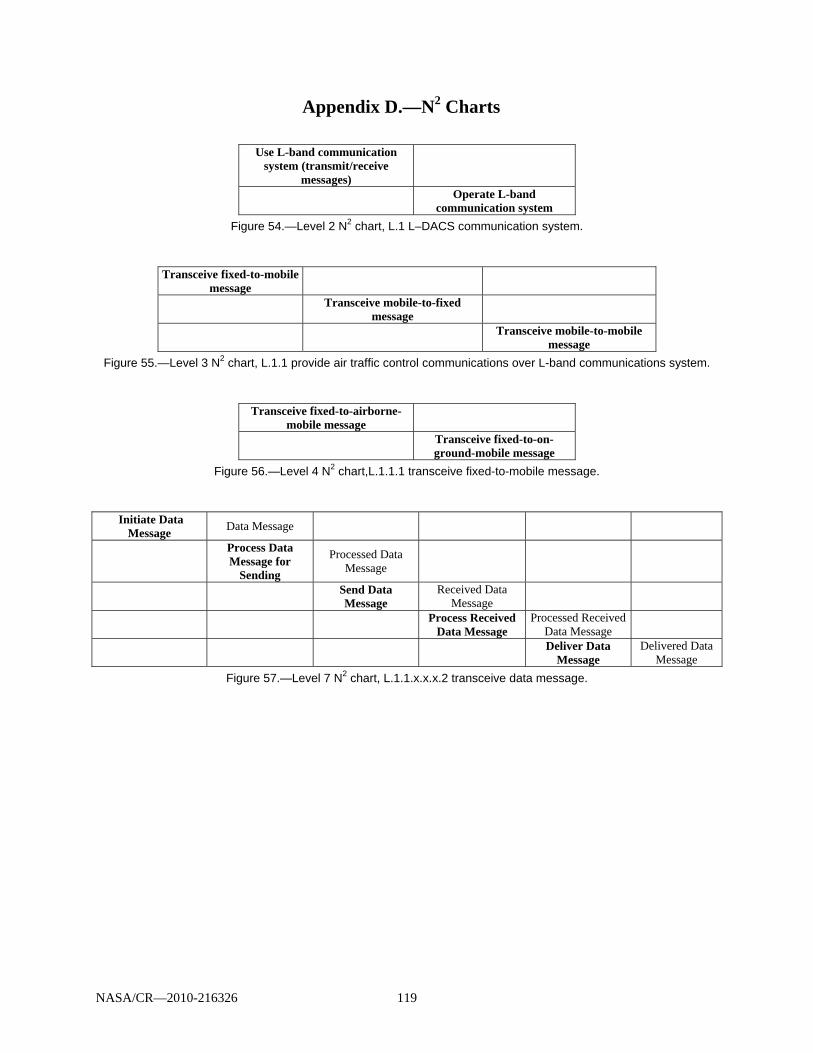
NASA/CR—2010-216326 119
Appendix D.—N2 Charts
Use L-band communication
system (transmit/receive messages)
Operate L-band communication system
Figure 54.—Level 2 N2 chart, L.1 L–DACS communication system.
Transceive fixed-to-mobile message
Transceive mobile-to-fixed message
Transceive mobile-to-mobile message
Figure 55.—Level 3 N2 chart, L.1.1 provide air traffic control communications over L-band communications system.
Transceive fixed-to-airborne-mobile message
Transceive fixed-to-on-ground-mobile message
Figure 56.—Level 4 N2 chart,L.1.1.1 transceive fixed-to-mobile message.
Initiate Data Message
Data Message
Process Data Message for
Sending
Processed Data Message
Send Data Message
Received Data Message
Process Received
Data Message Processed Received
Data Message
Deliver Data
Message Delivered Data
Message Figure 57.—Level 7 N2 chart, L.1.1.x.x.x.2 transceive data message.
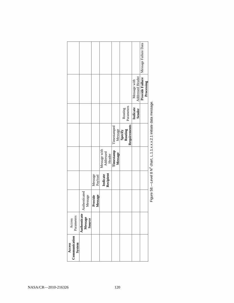
Acc
ess
Com
mu
nic
atio
n
Sys
tem
Acc
ess
Para
met
ers
A
uth
enti
cate
M
essa
ge
Sour
ce
Aut
hent
icat
ed
Mes
sage
Pro
vid
e M
essa
ge
Mes
sage
Pa
yloa
d
In
dic
ate
Rec
ipie
nt
Mes
sage
with
A
ddre
ssed
H
eade
r
Tim
esta
mp
M
essa
ge
Tim
esta
mpe
d M
essa
ge
Sp
ecif
y R
outi
ng
Req
uire
men
ts
Rou
ting
Para
met
ers
Ind
icat
e Se
nder
M
essa
ge w
ith
Add
ress
ed H
eade
r
P
rovi
de F
ailu
re
Pro
cess
ing
Mes
sage
Fai
lure
Dat
a
Fig
ure
58.
—Le
vel 8
N2 c
hart
, L.1
.1.x
.x.x
.2.1
initi
ate
dat
a m
ess
age.
NASA/CR—2010-216326 120

NASA/CR—2010-216326 121
Detect Failure Message Failure
Information
Determine Correction Message Correction
Parameters
Determine Indication Message Status
Information
Archive Information Archived Messages Figure 59.—Level 9 N2 chart, L.1.1.x.x.x.2.x.x. provide failure processing.
Encode Message
Encoded Message
Packetize Message Packetized, Encoded
Message
Compress MessageCompressed,
Packetized, Encoded Message
Add Checksum
Compressed, Packetized, Encoded
Message with Checksum
Provide Failure
Processing Message Failure
Data Figure 60.—Level 8 N2 chart, L.1.1.x.x.x.2.2 process data message for sending.
Apply Routing Packetized Message
Transmit Message Modulated and
Transmitted Packets
Transport MessageNetworked Messages
Receive Message Received and Demodulated
Packets
Provide Failure
Processing Message Failure
Information Figure 61.—Level 8 N2 chart, L.1.1.x.x.x.2.3 send data message.
Timestamp Message
Timestamped Messages
Decode Message Decoded Messages
Reconstitute Packetized Message
Message Packets
Decompress Message
Uncompressed Messages
Confirm
Checksum Message Payloads
Provide Failure
Processing
Failure Indication
Figure 62.—Level 8 N2 chart, L.1.1.x.x.x.2.4 process received data message.

NASA/CR—2010-216326 122
Access Communication
System
Authenticate Message Source
Message Source Authentication
Provide Message Source
Message Source
Indicate
Incoming Message
Indicated Incoming Message
Present Message Message Presented
Provide Failure
Processing
Failure Indication
Figure 63.—Level 8 N2 chart, L.1.1.x.x.x.2.5 deliver data message.
Transceive Airborne Mobile to Fixed Message
Transceive On-Ground Mobile to Fixed Message
Figure 64.—Level 4 N2 chart, L.1.1.2 transceive mobile-to-fixed message.
Monitor L-Band Communication System
Maintain L-Band Communication System
Configure L-Band Communication System
Figure 65.—Level 3 N2 chart, L.1.2 operate L-band communication system.
Determine Status Status Information Indicate Status Status Information
Verify Performance
Performance Information
Figure 66.—Level 4 N2 chart, L.1.2.1 monitor L-band communication system.
Perform Preventative Maintenance
Perform Corrective Maintenance
Figure 67.—Level 4 N2 chart, L.1.2.2 maintain L-band communication system.
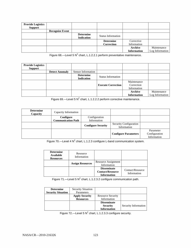
NASA/CR—2010-216326 123
Provide Logistics Support
Recognize Event
Determine Indication
Status Information
Determine Correction
Corrective Information
Archive
Information Maintenance
Log InformationFigure 68.—Level 5 N2 chart, L.1.2.2.1 perform preventative maintenance.
Provide Logistics
Support
Detect Anomaly Sensor Information
Determine Indication
Status Information
Execute CorrectionMaintenance Correction Information
Archive
Information Maintenance
Log InformationFigure 69.—Level 5 N2 chart, L.1.2.2.2 perform corrective maintenance.
Determine Capacity
Capacity Information
Configure Communication Path
Configuration Information
Configure Security Security Configuration
Information
Configure Parameters Parameter
Configuration Information
Figure 70.—Level 4 N2 chart, L.1.2.3 configure L-band communication system.
Determine Available Resources
Resource Information
Assign Resources Resource Assignment
Information
Disseminate
Contact/Resource Information
Contact/Resource Information
Figure 71.—Level 5 N2 chart, L.1.2.3.2 configure communication path.
Determine Security Situation
Security Situation Parameters
Apply Security Resources
Resource Security Information
Disseminate
Security Information
Security Information
Figure 72.—Level 5 N2 chart, L.1.2.3.3 configure security.


NASA/CR—2010-216326 125
Appendix E.—Spectrum Requirements for Unmanned Aircraft System (UAS) communications
This appendix presents Section 5 (Spectrum Requirements for UAS Communications) and Section 6 (Conclusions) of the proposed changes to Annex 16 of 5B/296-E in Reference 35.
E.1 Single UA Throughput Needs
E.1.1 Methodology 1
The two tables below are based on the results of the Annex 1 (of Ref. 35).
TABLE 24.—TERRESTRIAL ESTIMATED NONPAYLOAD THROUGHPUT REQUIREMENTS OF A SINGLE UNMANNED AIRCRAFT IN BITS/S
Proposal Command and control Air traffic control relay Sense-and-avoid Video/weather radar Airport surface 12 167 2×4855 9 120 270 000
30 997 Low altitude 12 167 2×4855 9 120 270 000a
30 997 Medium altitude 5 062 2×4855 9 120 27 000
23 892 High altitude 5 062 2×4855 9 120 27 000
23 892 aA factor representing a percentage value of video and weather radar data rate used at the low altitude could apply and is taken into account in Annex 3 of the Ref. 35.
TABLE 25.—SATELLITE ESTIMATED NONPAYLOAD THROUGHPUT REQUIREMENTS OF A SINGLE UNMANNED AIRCRAFT IN BITS/S
Proposal Command and control Air traffic control relay Sense-and-avoid Video/weather radarMedium altitude 5 062 2×4855 9 120 27 000
23 892 High altitude 5 062 2×4855 9 120 27 000
23 892
E.1.2 Methodology 2
TABLE 26.—MAXIMUM NONPAYLOAD THROUGHPUT REQUIREMENTSa OF A SINGLE UNMANNED AIRCRAFT IN BITS/S
Unmanned aircraft type
Control and Navaids
Air traffic control relay
Nonpayload surveillance datab
Large 2 437 4 855 287 849 Medium 2 437 4 855 279 120
Small 1 862 0 0 aAveraged over all operational phases. bIncludes video, weather radar, sense–and-avoid, etc.
E.2 Unmanned Aircraft System (UAS) Deployment Scenario
E.2.3 Methodology 1
Table 27 and Table 28 are based on the results of the Annex 2 [of the source document].
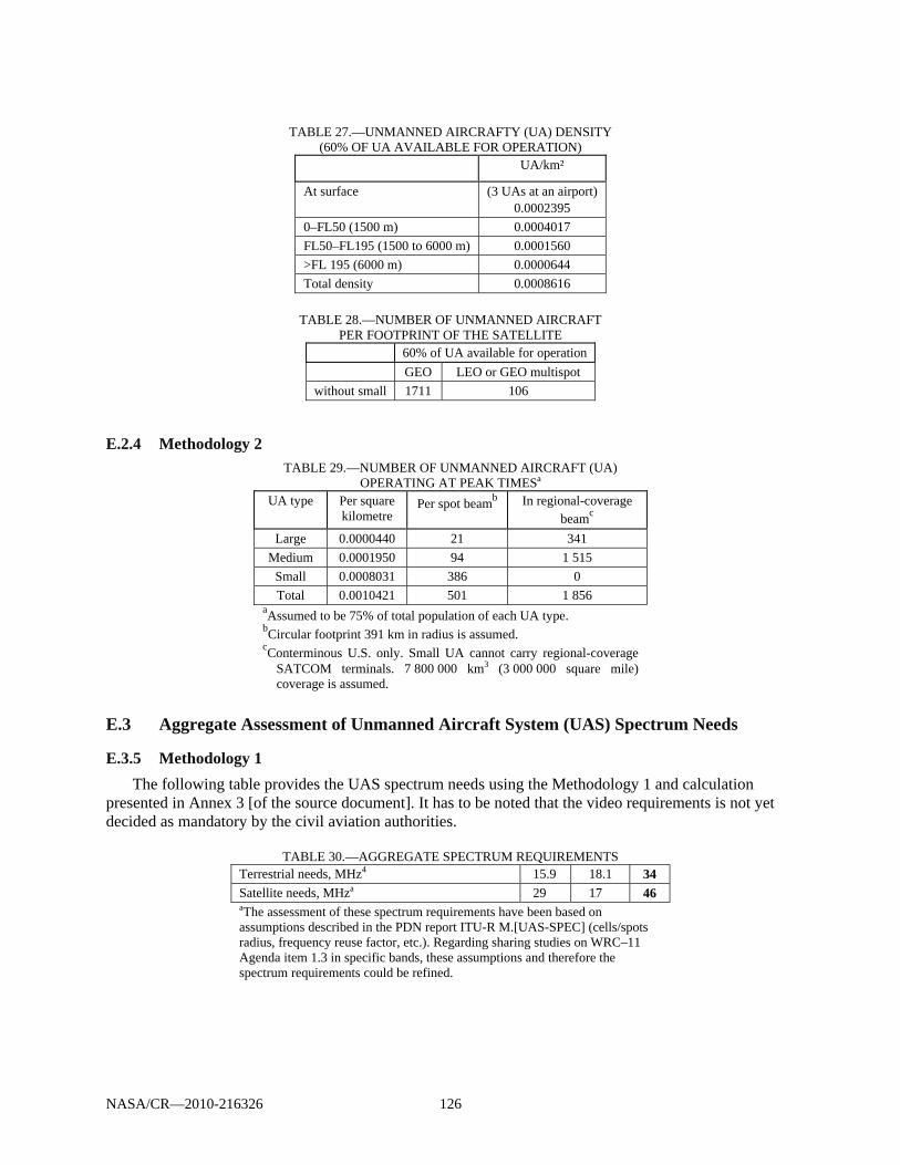
NASA/CR—2010-216326 126
TABLE 27.—UNMANNED AIRCRAFTY (UA) DENSITY
(60% OF UA AVAILABLE FOR OPERATION) UA/km²
At surface (3 UAs at an airport) 0.0002395
0–FL50 (1500 m) 0.0004017 FL50–FL195 (1500 to 6000 m) 0.0001560 >FL 195 (6000 m) 0.0000644 Total density 0.0008616
TABLE 28.—NUMBER OF UNMANNED AIRCRAFT
PER FOOTPRINT OF THE SATELLITE 60% of UA available for operation GEO LEO or GEO multispot
without small 1711 106
E.2.4 Methodology 2
TABLE 29.—NUMBER OF UNMANNED AIRCRAFT (UA) OPERATING AT PEAK TIMESa
UA type Per square kilometre
Per spot beamb In regional-coverage beamc
Large 0.0000440 21 341 Medium 0.0001950 94 1 515
Small 0.0008031 386 0 Total 0.0010421 501 1 856
aAssumed to be 75% of total population of each UA type. bCircular footprint 391 km in radius is assumed. cConterminous U.S. only. Small UA cannot carry regional-coverage
SATCOM terminals. 7 800 000 km3 (3 000 000 square mile) coverage is assumed.
E.3 Aggregate Assessment of Unmanned Aircraft System (UAS) Spectrum Needs
E.3.5 Methodology 1
The following table provides the UAS spectrum needs using the Methodology 1 and calculation presented in Annex 3 [of the source document]. It has to be noted that the video requirements is not yet decided as mandatory by the civil aviation authorities.
TABLE 30.—AGGREGATE SPECTRUM REQUIREMENTS
Terrestrial needs, MHz4 15.9 18.1 34
Satellite needs, MHza 29 17 46 aThe assessment of these spectrum requirements have been based on assumptions described in the PDN report ITU-R M.[UAS-SPEC] (cells/spots radius, frequency reuse factor, etc.). Regarding sharing studies on WRC–11 Agenda item 1.3 in specific bands, these assumptions and therefore the spectrum requirements could be refined.

NASA/CR—2010-216326 127
The detail of those requirements is shown in the figures below.
Figure 73.—Links involved for line of sight (LOS). Acronyms are defined in Appendix A.
Figure 74.—Links involved for beyond line-of-sight (BLOS) via satellite (with onboard processing).
Acronyms are defined in Appendix A.
ATC
UA
Remote PILOT
1
4
3
2
SatelliteSpectrum requirement
PILOT/SAT (UL+DL) = 1 + 4 = 24,5 MHz+
SAT/UAV (UL+DL) = 2 + 3 = 24,5 MHz
TOTAL BLOS = 2 x 24,5 MHz = 49 MHz
Forward link : 1. Uplink : Remote PILOT to satellite 2. Downlink : satellite to UA Return link : 3. Uplink : UA to satellite 4. Downlink : satellite to Remote PILOT
ATC
UAV
Control Station
Uplink : CS to UAV
1. CS to UAV
Downlink : UAV to CS 2. UAV to CS
Spectrum requirement
LOS = 1 +2 = 34 MHz
12
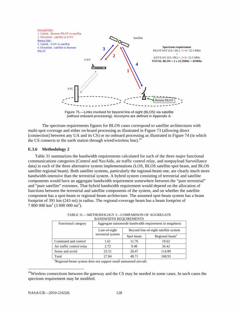
NASA/CR—2010-216326 128
Figure 75.—Links involved for beyond line-of-sight (BLOS) via satellite
(without onboard processing). Acronyms are defined in Appendix A.
The spectrum requirements figures for BLOS cases correspond to satellite architectures with multi-spot coverage and either on-board processing as illustrated in Figure 73 (allowing direct [connection] between any UA and its CS) or no onboard processing as illustrated in Figure 74 (in which the CS connects to the earth station through wired/wireless line).24
E.3.6 Methodology 2
Table 31 summarizes the bandwidth requirements calculated for each of the three major functional communications categories (Control and NavAids, air traffic control relay, and nonpayload Surveillance data) in each of the three alternative system implementations (LOS, BLOS satellite spot beam, and BLOS satellite regional beam). Both satellite systems, particularly the regional-beam one, are clearly much more bandwidth-intensive than the terrestrial system. A hybrid system consisting of terrestrial and satellite components would have an aggregate bandwidth requirement somewhere between the “pure terrestrial” and “pure satellite” extremes. That hybrid bandwidth requirement would depend on the allocation of functions between the terrestrial and satellite components of the system, and on whether the satellite component has a spot-beam or regional-beam architecture. The assumed spot-beam system has a beam footprint of 391 km (243 mi) in radius. The regional-coverage beam has a beam footprint of 7 800 000 km2 (3 000 000 mi2).
TABLE 31.—METHODOLOGY 2—COMPARISON OF AGGREGATE
BANDWIDTH REQUIREMENTS Functional category Aggregate nationwide bandwidth requirement in megahertz
Line-of-sight terrestrial system
Beyond line-of-sight satellite system
Spot beam Regional beama Command and control 1.61 11.76 19.62 Air traffic control relay 2.72 8.48 34.42 Sense and avoid 23.51 28.47 114.89 Total 27.84 48.71 168.93 aRegional-beam system does not support small unmanned aircraft.
24Wireless connections between the gateway and the CS may be needed in some cases. In such cases the spectrum requirement may be modifed.
ATC
UAV
Remote PILOT
1
4
3
2
Satellite
Spectrum requirementPILOT/SAT (UL+DL) =1+4= 22.5 MHz
+SAT/UAV (UL+DL) = 2+3= 22.5 MHz
TOTAL BLOS = 2 x 22.5MHz = 45MHz
Forward link : 1. Uplink : Remote PILOT to satellite2. Downlink : satellite to UAVReturn link : 3. Uplink : UAV to satellite4. Downlink : satellite to Remote PILOT

NASA/CR—2010-216326 129
E.4 Conclusion
Based on the assumptions and results of Methodology 1 and Methodology 2 above, the total UAS spectrum requirements are
34 MHz for a terrestrial LOS system 49 MHz for a spot-beam satellite system 169 MHz for a regional-beam satellite system, which can be shared between several satellites,
thereby reducing the overall spectrum requirement

NASA/CR—2010-216326 131
Appendix F.—L-Band Spectrum Applicability for Unmanned Aircraft System (UAS) Applications
This section is adopted from Reference 34. In support of spectrum selection and allocation the SC–203 conducted a comparative analysis of various frequency bands rating them in respect to suitability for unmanned aircraft system (UAS) applications. A relatively high rating was assigned to a lower part of the L-band (960 to 1024 MHz). The rationale for this relatively high rating is as follows:
The band is highly attractive for future UAS control use from a regulatory standpoint. It consists entirely of controlled-access aeronautical spectrum with an AM(R)S allocation. Its current worldwide spectrum allocation is internationally standardized and consistent from region to region.
Opportunities for finding bandwidth for AM(R)S in the 960 to 1024 MHz band depend primarily on exploiting certain characteristics of the DME and TACAN transmitters that are its principal current users. First, in the 979 to 1024 MHz part of the band all of those transmitters are at fixed ground locations. This would facilitate geographical frequency coordination between those DME/TACAN assignments and a future AM(R)S communications system. Second, a transmitted DME signal occupies a bandwidth narrower than its nominal 1-MHz channel width. If DME receivers are sufficiently selective, there may exist between adjacent DME channels a gap that could be utilized for AM(R)S (or UAS CC). Even if that is not the case for all DME receivers, many geographical areas have numerous unused DME channels that might be usable in their entirety by AM(R)S or UAS CC without RFI to or from DME. Consequently the band has been awarded a neutral rating in the “Potentially Available Bandwidth” category.
The band scores relatively well for link range, capacity, latency, and availability. Its LOS limitation and its relatively high free-space propagation loss (in comparison with 108 to 137 MHz) result in neutral ratings for range and capacity, but its terrestrial usage and its freedom from significant atmospheric loss earn it favorable ratings for latency and availability.
Co-site compatibility on aircraft is a major concern in this band. A 960 to 1024 MHz UA-borne communications transmitter would pose an interference risk to a collocated DME or UAT receiver and, most notably, to any collocated air traffic control radar beacon system (ATCRBS) or Mode S receiver operating at 1030 MHz. Present-day manned aircraft typically protect their onboard L-band (960 to 1215 MHz) devices from mutual co-site interference by means of a suppression bus that blanks the receivers each time a collocated in-band transmitter emits a pulse. If the transmitter has too high a duty cycle, this pulse-blanking method could unacceptably degrade receiver performance. If future airborne UA Control transmitters operate in the 960 to 1024 MHz band, they may have to employ some combination of power control, RF filtering, and/or low-duty-cycle operation to avoid interfering with collocated DME, UAT, and 1030-MHz receivers. The problem is likely to be more severe when the UA Control transmitter operates near the upper end of the 960 to 1024 MHz band, where RF filtering would afford the least protection to the 1030-MHz receivers. This co-site criterion is the only one for which the 960 to 1024 MHz band has received an unfavorable rating during the evaluation. However, it should be noted that the need for airborne transmissions in this band could be “finessed”, possibly at the cost of an additional airborne antenna, if a split-band UAS CC system is developed. For example, if uplink transmissions are situated in band 960 to 1024 MHz, but downlink transmissions are situated at C-band, the airborne cosite interference problem in this band would be eliminated.25
Because compact airborne antennas are feasible in the 960 to 1024 MHz band, it has received a favorable SWAP rating. New 960 to 1024 MHz ground radios would have to be installed, but they could 25 This would shift the airborne cosite problem to a higher band, but this might be desirable from an overall systems engineering perspective. C-band, for example, might offer the opportunity for greater downlink bandwidth (thereby matching the projected asymmetry in uplink and downlink data rates), and the UAS community might willingly forgo MLS. Furthermore, a C-band downlink could more easily support ground-based sectorized, multi-beam, or “smart” antennas designed to achieve high gain on the downlink, thereby allowing lower airborne transmit power and an overall reduction in background noise level for other users of the spectrum.

NASA/CR—2010-216326 132
cover most of the NAS from the existing ground sites used by VHF/UHF ATC A/G radios, so the band has been given a neutral rating under both of the “cost” criteria in the matrix. The band’s inherent security is deemed to be no worse than average for terrestrial A/G radio links, so a neutral rating has been given for that criterion as well.

NASA/CR—2010-216326 133
Appendix G.—References
1. National Airspace System: Concept of Operations and Vision for the Future of Aviation. First ed., RTCA, Washington, DC, 2002.
2. Concept of Operations for the Next Generation Air Transportation System. Version 2.0, Joint Planning and Development Office, June 13, 2007
3. Global Air Traffic Management Operational Concept. ICAO Document 9854, 2005. 4. Operating Concept of the Mobile Aviation Communication Infrastructure Supporting ATM Beyond
2015, EUROCONTROL, 30 April 2002. 5. Communications Operating Concept and Requirement for the Future Radio System (COCR Version
2.0), EUROCONTROL/FAA Future Communications Study Operational Concepts and Requirements Team, ACP/1-IP/5, May 2007.
6. Data Communications Safety and Performance Requirements (SPR) Draft E (FAA Evaluation Release) 30 April 2009.
7. Final Program Requirements for Data Communications, FAA, May 13, 2009. 8. National Airspace System: System Engineering Manual. Version 3.1, Federal Aviation
Administration ATO Operations Planning, June 6, 2006. 9. System Requirements Document, Next Generation Air/Ground Communications (NEXCOM)
Version 2.0. FAA–E–2958, FAA, Oct. 22, 2003. 10. FAA’s NextGen Implementation Plan 2009. NextGen Integration and Implementation Office,
Washington, DC, Revised Feb. 10, 2009. 11. FCI Aeronautical Data Services Definition Task Report. 2043–0001, ITT Corp., Mar. 31, 2009. 12. Next Generation Air Transportation (NextGen) System Integrated Work Plan (IWP)
http://www.jpdo.gov/iwp/IWP_V1.0_No_Appendices.pdf 13. National Airspace System (NAS) Enterprise Architecture https://nasea.faa.gov/ 14. Safety and Performance Requirements Standard for Air Traffic Data Link Services in Continental
Airspace (Continental SPR Standard). RTCA DO–290, 2004. 15. Gilbert, Tricia, et al.: Future Aeronautical Communication Infrastructure Technology Investigation.
NASA/CR—2008-215144, 2008. 16. National Airspace System, System Requirements Specifications. NAS SR–1000, Revision B
(Functional View), NAS Architecture 6, FAA/DOT, June 2008. 17. AS–IS System View (SV–2)—Existing and Near-Term (2009–2010) Telecommunications
Infrastructure. Presented by ATO–W, Telecommunications Services Group (TSG), NAS Enterprise Architecture Conference. June 24, 2009.
18. Stratoti, Stephen D.: NAS Enterprise Architecture, NextGen 2025 System Interface Description SV–1p, System Context, FAA, June 24, 2009.
19. VHF Air-Ground Communications System Improvements Alternatives Study and Selection of Proposals for Future Action, RTCA DO–225, 1994.
20. Fistas, Nikos; Phillips, Brent; and Budinger, James: Future Communications Study—Action Plan 17. Final Conclusions and Recommendations Report, DASC2007–4B6.
21. Anderson, Gregg: Data Communications, How We Want to Fly! Data Link Users Forum, FAA, Feb. 3, 2010.
22. Phillips, Brent; and Budinger, James: NextGen Air/Ground Communications Research, An Overview for FAA/John Marksteiner. FAA and NASA Glenn Research Center, Aug. 26, 2009.
23. Gilbert, Tricia, et al.: Identification of Technologies for Provision of Future Aeronautical Communications. NASA/CR—2006-214451 (TR06027), 2006.
24. Gilbert, Tricia, et. al.: Additional Technologies and Investigations for Provision of Future Aeronautical Communications, NASA/CR—2008-214987, 2008.
25. Delivering NextGen. FAA Collaborative Air Traffic Management, Jan. 29, 2009. 26. NAS EA 2025 OV–1 & OV–2: Operational Context. MITRE/CAASD, FAA NAS EA Conference,
June 24, 2009.

NASA/CR—2010-216326 134
27. Zakrzewski, Ed. ITT, “2025 System View (SV-2), NAS Enterprise Architecture Conference, June 24, 2009.
28. Hritz, Mike: System Wide Information Management (SWIM). SWIM TIM on Infrastructure and Technology, FAA, May 14, 2008.
29. Zelkin, Natalie; and Henriksen, Stephen: L-Band System Engineering—Preliminary Safety and Security Risk Assessment and Mitigation. NASA/CR–2010-216327, 2010.
30. Delille, Francois: Flight Object, Interoperability and SWIM. Air Traffic Alliance—a New Way of Thinking. Thales Air Systems, ICNS 2007 Conference, Herndon, May 1–3, 2007.
31. ICAO Aeronautical Communications Panel 18th meeting of the Working Group F, Montreal, Canada, 24 March – 3 April 2009.
32. NAS-Wide Information Services (NWIS) Architecture Development, CNS–ATM TASK 15, TR03010, ITT Industries, Advanced Engineering and Sciences, Feb. 22, 2003.
33. Signal-in-Space Minimum Aviation System Performance Standards (MASPS) for Advanced VHF Digital Data Communications Including Compatibility With Digital Voice Techniques, RTCA DO–224B, 2005,
34. Control and Communications Product Team: SC–203 Unmanned Aircraft Systems. Issue Paper SC203-CC011_UAS Spectrum_vO_15May09, UAS Spectrum, RTCA, Inc.
35. Preliminary Draft New Report ITU–R M [UAS–SPEC], Characteristics of unmanned aircraft systems (UAS) and Spectrum requirements to support their safe operation in non-segregated airspaces, Document No. USWP5B09–25, ITU, Aug. 4, 2009
36. RTCA DO–304. Guidance Material and Considerations for Unmanned Aircraft Systems. Washington, DC, USA: RTCA. 2007.
37. DeGarmo, Matt: Operational Services and Environmental Definition (OSED) for Unmanned Aircraft Systems (UAS), Draft, 224–09/SC203–036, RTCA, Inc., Oct. 23, 2009.
38. http://www.eurocontrol.int/communications/public/standard_page/LDACS.html 39. Pouzet, Jacky (Head of CoE/CN/COM Unit): Future Aeronautical Communication System—FCI:
Update on European Activities. DLK Users Forum, Brussels, Belgium, Sept. 2009. 40. Fistas, Nikos: Future Aeronautical Communication System—FCI. 9th ICNS Conference, Arlington,
VA, 2009. 41. European Air Traffic Management Master Plan. Ed. 1, 2009. 42. NextGen Mid-Term Implementation Task Force Interim Report. RTCA, Washington, DC, 2009. 43. World Radiocommunication Conference (WRC-07), Geneva, 22 October - 16 November 2007,
Agenda of the Conference 44. Biggs, Michael: Spectrum Issues and WRC–07 Preparation. Presented at the 2007 ICNS Conference,
Session J: Aviation Spectrum, Herndon, VA, 2007. 45. Roberts, Darren. B-AMC Project Deliverable D1 Draft 1.0, Mileridge, August 14, 2007. 46. Systematic Interference Investigations, DLR and USG, January 31, 2008. 47. Proposed L-Band Interference Scenarios, v.1.0, DLR, February 2008. 48. Dobrosavljevic, Zoran. Roke Manor Research, Ltd. DME and B-AMC Co-Existence Study Report
Edition: 2.0, Roke Manor, February 28, 2008. 49. University of Salzburg. Draft B-AMC Frequency Plan, March 27, 2008. 50. Sajatovic, Miodrag, et al.: L-DACS1 System Definition Proposal: Deliverable D3 –Design
Specifications for L-DACS1 Prototype, Edition 1.0, Frequentis, DLR, University of Salzburg, and Selex, April 27 2009, p.13.
51. LDACS1 D2 Final Deliverable Edition: 1.0, Frequentis, DLR, University of Salzburg, and Selex, February 13, 2009
52. L–DACS2 System Definition Proposal: Deliverable D1 Edition 0.34, EGIS AVIA, March 11, 2009 53. L–DACS2 Transmitter and Receiver Prototype Equipment Specifications: Deliverable D3 Edition
1.2, EGIS AVIA, June 18, 2009 54. National Airspace System Communications System Safety Hazard Analysis and Security Threat
Analysis. Version 1.0, FAA, Feb. 21, 2006.

REPORT DOCUMENTATION PAGE Form Approved
OMB No. 0704-0188 The public reporting burden for this collection of information is estimated to average 1 hour per response, including the time for reviewing instructions, searching existing data sources, gathering and maintaining the data needed, and completing and reviewing the collection of information. Send comments regarding this burden estimate or any other aspect of this collection of information, including suggestions for reducing this burden, to Department of Defense, Washington Headquarters Services, Directorate for Information Operations and Reports (0704-0188), 1215 Jefferson Davis Highway, Suite 1204, Arlington, VA 22202-4302. Respondents should be aware that notwithstanding any other provision of law, no person shall be subject to any penalty for failing to comply with a collection of information if it does not display a currently valid OMB control number. PLEASE DO NOT RETURN YOUR FORM TO THE ABOVE ADDRESS.
1. REPORT DATE (DD-MM-YYYY) 01-09-2010
2. REPORT TYPE Final Contractor Report
3. DATES COVERED (From - To)
4. TITLE AND SUBTITLE L-Band Digitial Aeronautical Communications System Engineering--Concepts of Use, Systems Performance, Requirements, and Architectures
5a. CONTRACT NUMBER
5b. GRANT NUMBER
5c. PROGRAM ELEMENT NUMBER
6. AUTHOR(S) Zelkin, Natalie; Henriksen, Stephen
5d. PROJECT NUMBER NCC05CA85C 5e. TASK NUMBER
5f. WORK UNIT NUMBER WBS 031102.02.03.02.0677.09
7. PERFORMING ORGANIZATION NAME(S) AND ADDRESS(ES) ITT Corporation Advanced Engineering & Sciences Division 12975 Worldgate Drive Herndon, Virginia 20170
8. PERFORMING ORGANIZATION REPORT NUMBER E-17260
9. SPONSORING/MONITORING AGENCY NAME(S) AND ADDRESS(ES) National Aeronautics and Space Administration Washington, DC 20546-0001
10. SPONSORING/MONITOR'S ACRONYM(S) NASA
11. SPONSORING/MONITORING REPORT NUMBER NASA/CR-2010-216326
12. DISTRIBUTION/AVAILABILITY STATEMENT Unclassified-Unlimited Subject Category: 04 Available electronically at http://gltrs.grc.nasa.gov This publication is available from the NASA Center for AeroSpace Information, 443-757-5802
13. SUPPLEMENTARY NOTES
14. ABSTRACT This NASA Contractor Report summarizes and documents the work performed to develop concepts of use (ConUse) and high-level system requirements and architecture for the proposed L-band (960 to 1164 MHz) terrestrial en route communications system. This work was completed as a follow-on to the technology assessment conducted by NASA Glenn Research Center and ITT for the Future Communications Study (FCS). ITT assessed air-to-ground (A/G) communications concepts of use and operations presented in relevant NAS-level, international, and NAS-system-level documents to derive the appropriate ConUse relevant to potential A/G communications applications and services for domestic continental airspace. ITT also leveraged prior concepts of use developed during the earlier phases of the FCS. A “middle-out” functional architecture was adopted by merging the functional system requirements identified in the “bottom-up” assessment of existing requirements with those derived as a result of the “top-down” analysis of ConUse and higher level functional requirements. Initial end-to-end system performance requirements were derived to define system capabilities based on the functional requirements and on NAS-SR-1000 and the Operational Performance Assessment conducted as part of the COCR. A high-level notional architecture of the L-DACS supporting A/G communication was derived from the functional architecture and requirements.15. SUBJECT TERMS Aircraft communication; Wireless communications; Air traffic control
16. SECURITY CLASSIFICATION OF: 17. LIMITATION OF ABSTRACT UU
18. NUMBER OF PAGES
151
19a. NAME OF RESPONSIBLE PERSON STI Help Desk (email:[email protected])
a. REPORT U
b. ABSTRACT U
c. THIS PAGE U
19b. TELEPHONE NUMBER (include area code) 443-757-5802
Standard Form 298 (Rev. 8-98)Prescribed by ANSI Std. Z39-18