L A U INSTALLATION, M OPERATION & R … P D / S D M A G I T A T O R M A N U A L INSTALLATION,...
43
APD / SDM AGITATOR MANUAL INSTALLATION, OPERATION & MAINTENANCE Instructions for CLEVELAND MIXER APD Agitator Series Models: APD, APDO - Open Tank, APDS/M - Sealed or Closed Tank, SDM - Side Entry www.clevelandmixer.com Toll Free: 1-800-243-1188 Fax: 860-669-1199
Transcript of L A U INSTALLATION, M OPERATION & R … P D / S D M A G I T A T O R M A N U A L INSTALLATION,...

AP
D/
SD
MA
GIT
ATO
RM
AN
UA
L
INSTALLATION,OPERATION &MAINTENANCEInstructions forCLEVELAND MIXERAPD Agitator SeriesModels: APD, APDO - Open Tank,APDS/M - Sealed or Closed Tank,SDM - Side Entry
www.clevelandmixer.comToll Free: 1-800-243-1188Fax: 860-669-1199

Introduction
How to use this Manual
Uncrating & Inspection
Lifting & Moving
Pre Installation Checklist
Mixer Assembly
Fixing Element
Torque Charts
Shafts, Impellers, Couplings
Expansion Chamber
Auto Lubricator
Lubrication
Mixer Positioning
Seals
Parts Breakdown (general)
Deactivation, Storage, Maint.
Trouble Shooting
Installation, O&M
1
2-6
2-6, 3-13
6
10-12, 16, 24-24.1
8-9
13
14
13-15,26-28
15.2-15.3
17-19
20-21
22-23
25
TABLE OF CONTENTS
2-6, 5-7
2-6
Cleveland Mixer 2012 11/13/12 rev. 3 - JMN

This Owner's Manual provides information and instructions on the installation, operation andmaintenance of Cleveland Mixer Model APD Mixers. The Table of Contents will help you findany information you might need. To obtain maximum performance and trouble free servicefrom this Cleveland equipment, follow all instructions carefully.
HOW TO USE MANUAL
INTRODUCTION
UNIT RATINGS & APPLICATIONSOperate mixer reducers only at the horsepower and speed indicated on the nameplate.Consult Cleveland Mixer before making any changes in operating conditions of APD units,differing from "as built".
Cleveland Mixer warrants that, for a period of one year from the date of shipment, theproduct described herein will successfully deliver its rated output as indicated in thequotation, provided it is properly installed, maintained, correctly lubricated and operated inthe environment within the limits of speed, torque or other load conditions for which it wasdesigned. Unapproved modifications to the equipment and/or running the equipment in anyother way than what it was originally designed for voids the warranty.
WARRANTY
HOW TO CONTACT USFor questions, tech support or parts & service:
Phone: 860-669-1199 or toll free 800-243-1188Fax: 860-669-7461Email: [email protected]
1
The Cleveland Mixer warrantee applies to only items furnished by Cleveland Mixer. All otherequipment (tanks, mounting structures, power sources, process equipment) & designs arethe responsibility of others. Cleveland Mixer does not warrant, guarantee or assume anyresponsibility for the design or construction of the mounting structure for the mixer.

2
INSTALLATION
Uncrating & InspectionBe sure to use care when uncrating andhandling the mixer. Certain parts suchas turbine hubs, turbine blades,couplings, steady bearings, seals,hardware, spare parts and accessoriesmay be packed in boxes or inside of thecrate.
Make sure all components areaccounted for before discarding thepackaging materials or crates. It iscommon for parts to be missed oroverlooked.
The mixer should be carefully checkedfor possible shipping damage at time ofdelivery. Any damage should bereported immediately to theTRANSPORTATION COMPANY ANDCLEVELAND MIXER.
Improper handling may cause damageto the mixer and seriously reduce theservice life. The shaft has beenstraightened to within .003" per foot.Extra care should be taken to see that itis not damaged in the process ofuncrating.
Lifting & Moving
Always use a crane, hoist or othermechanical assistance to move APDunits. Exercise care to prevent damagewhen moving. Lift only at designed liftpoints. Insure that adequate safetymeasures are taken to protectpersonnel during transportation. Protectthe mounting surface from damage.
Most mixer operational problems can beavoided by following proper installation andoperation instructions. The following is a list ofsuggestions to help insure proper installationand therefore satisfactory mixer service.
Pre Installation Check List
Before permanently wiring the motor,check for the correct rotation of theshaft. Standard rotation is clockwise.Gear reducers reverse rotation, takethat into account when wiring the motor.Do the initial test run before theimpellers are installed. If the outputshaft is turning the in the wrongdirection, you will have to reverse themotor leads to change the direction. Allwiring should be done by a qualifiedelectrician.
1.
2. Read and follow the instructions of alltags and nameplates before operating.
Check the operating full load motoramperage and voltage before operatingthe mixer.
3.
4. The mixers are designed to run againsta design specific gravity. DO NOT RUNMIXER DRY. Always test run in fluidless than or equal to design specificgravity and viscosity unless otherwisestated.
When starting the mixer, make surethat the impeller(s) can spin freely.Check to make sure the rotating bladeswon't hit baffles, tank walls, people,equipment, etc. During service, do notstart the mixer if the impeller(s) areburied in solids.
5.

Open tank models are typicallymounted to a pair of beams or bridgework that traverses the tank. Thissuperstructure can be eitherindependent from the vessel or anintegral part of the tank itself.
Closed or sealed tank units are typicallymounted on ASA schedule nozzles andincorporate some style of sealingmechanism to contain pressure orrogue emissions.
In either case it is critical that themounting has a solid foundation whichis rigid enough to withstand the torqueof the mixing and the horsepower of themotor. Excess vibration and movementcan cause critical damage to the mixerand tank.
The mixer should be mounted to sitlevel 90° for vertical units and 0°/180°for horizontal side mounted units.
We suggest laser aligning the shaftfrom the hollow output of the reducer tothe bottom of the tank. Shaft alignmentwill help to assure the shaft will run true.You do not want the shaft sitting oneven the slightest angle. An angled ormisaligned shaft can cause excessvibration and speed wobble which cancause critical damage to the mixer andthe tank.
Be sure that the turbine blades canfreely rotate a full 360°. Be sure that theblades will not come in contact with:baffles, dip tubes, tank walls, etc. Referto approval drawings for clearanceinformation.
3
As previously mentioned; to ensure a longservice life and dependable performance, themixer must be rigidly supported and theshaft(s) accurately aligned. The shaftshould not move more than 1/32" per foot ofshaft due to deflection of the structure. It isimportant that the gear reducer sits level
(unless it was specifically designed forangle mounting) for its lubrication system towork properly. Be sure to take into accountwhere the oil drain plug is before mounting.The following describes the minimumprecautions required to accomplish this end.
FoundationThe responsibility for the design andconstruction of the foundation lies with theuser. The foundation must be adequate towithstand normal operating loads andpossible overloads while maintainingalignment to attached system componentsunder such loads.
Concrete FoundationIf a concrete foundation is used, steelmounting pads and bolts of sufficient size todistribute the stress into the concrete shouldbe grouted into the foundation.
If a structural steel foundation is used (i.e.wide flange beams or channels), a baseplate of suitable thickness should be usedand should extend under the entire unit.
Steel Foundation
MIXER ASSEMBLY

Mixer Assembly
Incorrect mounting is often a cause ofmechanical difficulty with a mixer.Unless specified on the mixer assemblydrawing, the mixer shaft is designed torun in a true vertical position. Shimsshould be used in installations wherethe mounting surface isn't level.
For flange mounted unit; if a structuralsteel foundation is used, a base plateor sole plate of suitable thicknessshould be used and should extendunder the entire unit. If a bulk headplate is used, it should be of properstrength to minimize bucklingdistortions. Make sure that the plate sitsflat and level before installing the mixer.An uneven mounting plate can causeserious problems with shaft andimpeller runout.
Both the hollow shaft and the driven shaft shouldbe liberally lubricated before assembly. Thereducer must slide freely onto the driven shaft. Donot hammer or force the unit into place.The lower mixer shaft extension consists of oneor more rigid shaft sections and will accommodateone or more impeller assemblies.This shaft will either mount directly to the gearreducer as one piece shaft or it will be assembledfrom sections of shaft that are joined by boltedflanged connections.
SHAFT & IMPELLER INSTALLATION - VERTICAL MOUNT
4
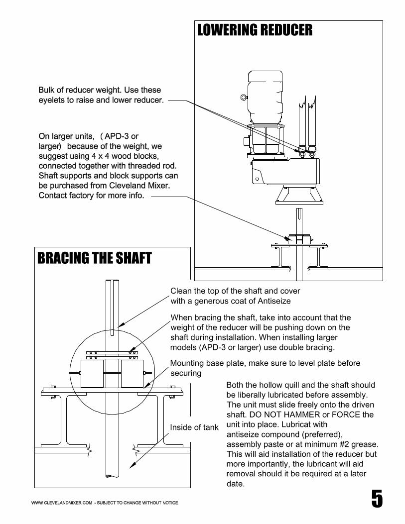
BRACING THE SHAFT
Clean the top of the shaft and coverwith a generous coat of Antiseize
When bracing the shaft, take into account that theweight of the reducer will be pushing down on theshaft during installation. When installing largermodels (APD-3 or larger) use double bracing.
Mounting base plate, make sure to level plate beforesecuring
Inside of tank
Both the hollow quill and the shaft shouldbe liberally lubricated before assembly.The unit must slide freely onto the drivenshaft. DO NOT HAMMER or FORCE theunit into place. Lubricat withantiseize compound (preferred),assembly paste or at minimum #2 grease.This will aid installation of the reducer butmore importantly, the lubricant will aidremoval should it be required at a laterdate.
LOWERING REDUCER
5

6
FIXING ELEMENT - STRAIGHT SHAFT
FIXING ELEMENT - SHOULDERED SHAFT
1. Insert shaft key through the top of thehollow output shaft. Push key down until it'slevel with the top of the shaft keyway.
2. Insert snap ring into the snap ring groove inthe hollow output shaft. The snap ring will sitabove the shaft to prevent the shaft frompushing upward. The groove is typically 1-2"down into the quill.
3. Insert fixing element cap plate, lock washerand cap plate bolt. We suggest using a fewdrops of thread locker on the cap plate bolt andthen torqueing the bolt.
1. Follow steps 1 & 3 from the instructionsabove. The procedure for installing the fixingelement to a shouldered shaft is the sameaccept that the shouldered shaft does notrequire a snap ring. The shoulder will preventthe shaft from pushing upwards. The fixingelement cap plate can be torqued right to thetop of the shaft.
SNAP RING

MOUNTING - LIFTING
7
LIFTING POINTS - VERTICAL MOUNT
LIFTING POINTS - HORIZONTAL MOUNT
Use eye bolts to lift the mixerfrom the center of the reducer.The bulk of the weight shouldbe supported by these twobolts. Use a third strap underthe reducer to prevent themixer from flipping upside downor sideways. Never support theweight of the mixer by themotor or motor adapter. Heavyoddly shaped equipment shouldalways be moved by aprofessional.
Use eye bolts to lift the mixer fromthe center of the reducer. The bulkof the weight should be supported bythese two bolts. Use a third strapunder the motor to prevent the mixerfrom flipping upside down orsideways. Never support the weightof the mixer by the motor or motoradapter. Heavy oddly shapedequipment should always be movedby a professional.

7.1
REDUCER AND MOUNTING PLATE BOLTS
MOUNTING
These bolts are also subject to high loads and should be properly torqued toprevent bolt stretch and reducer wobble.For situations where the reducer is on the larger side, the shafting is on thelonger side and/or the unit is equipped with large turbines; use additional careto make sure that the bolts are installed and torqued properly.
If set screws are used for axial retention, they should be tightened evenly. Itis a good idea to use a drop of "Lock-Tite" or some form of thread locker onthe set screws before installing them. This will help in the prevention of setscrew back off. Flats or dimples may be used on the drive shafts to give setscrews something to grab onto.
SET SCREWS
SNAP RING
Snap rings are used to retainthe shaft from sliding upwardin cases where the shaftdoesn't have a shoulder. Thesnap ring should be insertedinto the grove inside of thehollow output shaft. The snapring will sit just above the topof the drive shaft. There maybe a space between the capplate and the top of the shaft.Cleveland Mixer suggests theuse of a thread lockingadhesive on the cap platebolt; the cap plate bolt shouldscrew down into the driveshaft at least the samediameter of the bolt if not allthe way to the end of theshaft thread. This bolt shouldbe torqued in accordancewith the torque chart in thismanual.

8
IMPELLERS & SHAFTS
BOLT SIZEALL MATERIALS
FOOT POUNDS NUMBER1/2 - 13 50 68
5/8 - 11 90 122
3/4 - 10 160 217
7/8 - 9 140 190
1 - 8 220 2981 - 1/8 - 7 300 407
1 - 1/4 - 7 420 570
1 - 3/8 - 6 556 754
10037401 - 1/2 - 6
1 - 3/4 - 5 825 1118
2 - 4 - 1/2 1125 1525
2 - 1/4 - 4 - 1/2 1725 2338
2 - 1/2 - 4 2300 3117
* Lubricate bolt before installation. Torque each bolt tothe appropriate value as shown above.
NOTE: The bolt torques shown here will develop a fastener pre load of 80 % of the fastener'sminimum yield.
COUPLING BOLTS - LOW SPEED SHAFT: At least Grade 5. The torque required may befound using the Grade 5 chart and reading across from the bolt diameter to be used. Ifstainless bolts are used, proceed with the proper stainless steel chart. Any looseness inthese bolts causes the coupling to apply a shear load on the bolt and a high impact tensileload or shock load.This shock load and shear load can cause the bolts to snap, the holes to elongate or thecoupling to fail to keep the shaft running straight which can have numerous disastrouseffects on the mixer.
TORQUE VALUES FOR THRUST BOLTS
1. Tighten all fasteners to the values shown unless specifically instructed to do otherwise.2. Lubricate all fasteners at assembly with grease, oil or anti-seize material.3. If fasteners cannot be lubricated, multiply table values by 1.334. Loose bolts can cause severe damage. It is very important to check all fasteners on aregular basis to make sure they haven't come loose. ****5. If your process material is corrosive or sanitary, check the wetted hardware to make sureit is the correct grade before assembly.

9
1 - 1/2 - 6
1 - 3/8 - 6
1 - 1/4 - 7
1 - 1/8 - 71 - 8
7/8 - 9
3/4 - 10
5/8 - 11
1/2 - 13
NmFT-LB
BOLTSIZE
CARBON STEEL
IMPELLERS & SHAFTS
3/8 - 16
9/16 - 12
Grade 2
FT-LB Nm
Grade 5
FOOT-LBS NUMBER
Stainless Steel, Alloy 20,Monel, Hastelloy C
15 20 23 30 2115
38 51 56 77 37 50
7254112836850
68 92 113 152 74 101
178131271200163120
105 143 296 401 212 287
165 224 443 601 318 432
225 305 596 808 450 610
315 428 840 1139 636 862
417 566 1003 1495 834 1130
555 752 1463 1983 1470 1500
TORQUE VALUES FOR RIGID SHAFT COUPLINGS
1. Tighten all fasteners to the values shown unless specifically instructed to do otherwise.2. Lubricate all fasteners at assembly with grease, oil or anti-seize material.3. If fasteners cannot be lubricated, multiply table values by 1.334. Loose bolts can cause severe damage. It is very important to check all fasteners on aregular basis to make sure they haven't come loose. ****5. If your process material is corrosive or sanitary, check the wetted hardware to make sureit is the correct grade before assembly.
NOTE: The bolt torques shown here will develop a fastener pre load of 80% of the fastener'sminimum yield.
COUPLING BOLTS - LOW SPEED SHAFT: At least Grade 5. The torque required may befound using the Grade 5 chart and reading across from the bolt diameter to be used. Ifstainless bolts are used, proceed with the proper stainless steel chart. Any looseness inthese bolts causes the coupling to apply a shear load on the bolt and a high impact tensileload or shock load.This shock load and shear load can cause the bolts to snap, the holes to elongate or thecoupling to fail to keep the shaft running straight which can have numerous disastrouseffects on the mixer.
* Lubricate bolt before installation. Torque each bolt tothe appropriate value as shown above.

10
IMPELLERS & SHAFTS
SINGLE IMPELLER INSTALLATION
Both the hollow shaft andthe driven shaft shouldbe liberally lubricatedbefore assembly. Thereducer must slide freelyonto the driven shaft. Donot hammer or force theunit into place.The lower mixer shaftextension consists of oneor more rigid shaftsections and willaccommodate one ormore impellerassemblies.This shaft will eithermount directly to thegear reducer as onepiece shaft or it will beassembled from sectionsof shaft that are joined bybolted flangedconnections.
Impellers andturbines can havedifferent numbers ofblades. There shouldbe a blade for everyhub ear. Bladestypically mount tothe bottom of theear. Check approvaldrawing or callfactory forconfirmation.
Hook end of Gibkey sits under hubto prevent the hubfrom sliding down.
Blades bolt to bottom of hunears.
Torque hardware
Hub marked "TOP" up
Set screw torqued
Clockwise Rotation
Lock washer, Nut
Bolt

IMPELLERS & SHAFTS
11
Now that the impeller hub is on the shaft, firmly bolt the impeller hardware (blades, discs,stabilizers) into place. All in-tank fasteners involving the couplings and turbine hubs do notuse lock washers. All in-tank fasteners should be rechecked for tightness after 1500 hours ofoperation. It is also recommended to check at scheduled shut down periods. All shaft andimpeller bolts should be torqued to the values shown in the torque value table in this manual.
The upper shaft or shaft section, if it is a multi-piece shaft assembly, will have either awelded coupling or a removable tapered bore coupling that will mate with the low speedshaft on the reducer.The welded coupling is used on upper shaft sections for open tank mixers that do not haveany impellers mounted to it that would need to be removed. With a taper bore coupling, theupper shaft is assembled to the taper coupling and held in place by the internal cap platebolted to the top of the shaft.The rigid coupling is the welded flange type that requires no installation and would normallybe found attached to the upper shaft assembly, either in or out of the process. There may beseveral of these connections between shaft sections in the assembly.
IMPELLER INSTALLATION1. XTF-3R Impeller blades and hubs are shipped disassembled.2. Slide the hub to the desired location over the key (the hub should be marked with "TOP"make sure that side is up). Tighten the set screw over the key. Impellers over 50 inches indiameter are provided with Gib keys. Lower the hub slowly until it rests on the Gib, thentighten the set screw.3. Assemble the blades to the underside of the hub using four hex head cap screws and nutsper blade. Torque all bolts to the required specifications.4. Retighten all bolted connections using proper torque settings before starting the mixer.
TAPER BORE COUPLING
RIGID COUPLING
KEYLESS RIGID COUPLING
**Follow B-Loc instructions providedw/ B-Loc coupling.

12
IMPELLERS & SHAFTS
STEADY BEARING
Steady Bearings: When specified, mixers are suppliedwith an optional in-tank steady bearing. A steadybearing is an in-tank; process lubricated bearing usedto support and restrain the lower end of the mixer.Steady bearings permit the safe use of smallerdiameter, longer shafts, operating at higher rotationalspeeds. For proper steady bearing performance, themixer shaft must be straight and steady bearingcentered on the shaft. For pad type steady bearings,be sure that the vessel top and bottom flanges areparallel and concentric within .003" per foot ofseparation. Shim bracket mounted steady bearingsbetween the bracket and bearing housing, so theystay centered on the shaft.
Even though a shaft may bestraight and properly machined, itmay appear to wobble a bittoward the bottom. For longershafts(20-30') 1/2 the shaftdiameter may be acceptable.However, for shorter shafts, thewobble should not exceed 1".
For best results, thesteady bearing should belaser aligned with thereducer quill and weldeddown. Steady bearingbushing should beinspected for wear andtear during every shutdown period. If thebushings are worn downto the metal of the bushinghousing, they should bereplaced. Call ClevelandMixer with your mixer'sserial number forreplacement bushings.
STANDARD - Impellersshould rotate clockwisewhen looking down fromthe top. When wiring,take into account thatgear reducers reverserotation. Follow themotor wiring guide forwiring instructions. Linesmay need to be switchedin order to reverse rotation.Always check rotationbefore putting your mixerinto operation.
STEADY BEARING - Bushing andbushing housing should be checkedperiodically for excessive wear. If yourinstallment alignment is precise, youwill experience less bushing wear.

IMPELLERS & SHAFTS
KEYLESS RIGID COUPLINGKeyless Rigid Couplings eliminate the need for shaft keys and keyways. Keyless rigidcouplings will come with their own set of installation instructions specific to the size andstyle of coupling required for your mixer's design.

13
Vertical mounted APD mixers will be supplied with an oil expansion chamber. The oilexpansion chamber should be mounted to the reducer with the tank above the oil fill line.The oil expansion chamber offers pressure relief without allowing moisture to contaminatethe gear case.
1. After the mixer is securely mounted and the shaft is installed: Remove the vent plug fromthe gear reducer on the NEMA face above the gear case Make sure that the Oil ExpansionChamber is mounted above the oil fill line.2. Screw the adapter fitting into the reducer housing port. Make sure to use all gasketsprovided.3. Mount the chamber support leg of the overflow tank to one of the NEMA mounting boltsjust above the gear case4. Attach vent hose assembly to adapter fitting.5. Do a final check to make sure that the breathers are open and above the oil fill line, theexpansion chamber is mounted and connected and the auto lubricator is operating properly.
INSTALLATION INSTRUCTIONS
4321
INSTALLING THE OIL EXPANSION CHAMBER
Expansion chambermust be mounted abovethe oil fill line.
The lower end of the line mustbe connected into the gear case.
Autovent Plug
***REMOVE rubber stripfrom autovent plug beforeoperating mixer.

14
STANDARD LUBRICANT - KLUBER PETAMO GHY 133 (synthetic)LUBRICANT VOLUME - 120mL (4oz)OPERATING TEMP RANGE - (-22°F - 302°F) (-30°C - 150°C)DISCHARGE TIME - 12 months at 25°C (77°F)OPERATING POSITION - Independent of mounting position operates even under water.MALE CONNECTING THREAD - 1/4" NPT
CLEVELAND MIXER AUTO LUBRICATOR SPECS
INSTALLATION INSTRUCTIONS
1. Remove the plug from the male connecting thread.2. Screw male fitting into bearing housing within Adapter.3. Insert activating screw into end of canister. Tighten until ring-eyelet breaks off.4. Replace every twelve months.
For the bearings used in Cleveland Mixer products, a 12-month lubrication period isstandard, indicated by a gray activating screw, this applies for an average operating time of8 hours per day. For longer operating times, the replacement interval decreases to 6 months.Lubrication canisters are also available for cold temperature applications. Contact factory formore information.
After tightening the plastic activating screw, theZinc-Molybdenum pellet drops into the citric acidelectrolyte. The chemical reaction builds uppressure that causes the piston to move forward.The lubricant is continuously injected into thelubrication point. At the end of the lubricationperiod, the discharge indicator cap becomes fullyvisible indicating that the lubricant has been fullydischarged. The lubrication period is determinedand defined by the color of the activation screw. Automatic Lubricator
With all APD-7 and larger mixers, Cleveland Mixer supplies the larger C-face motor adapterswith an Automatic Lubricator. This will provide additional grease lubrication to the outboardbearing. As the pressure from the lubricator canister pushes the new grease into the bearing,the old grease will flow into the cavity towards the gearbox. When the cavity is filled with"used" grease, the pressure from the new grease pushes the used grease into the gearboxthru the input seal. The old grease mixes with oil but will not cause harm to the gearing orbearings. Regular oil changes with the gearbox will remove the old grease which has beenpushed into the gearbox.
AUTOMATIC LUBRICATOR

15
GREASE FITTINGSAdd grease to high speed and slow speed bearings throughgrease fittings. APD reducers will come with grease fittingspre-installed in the appropriate locations. Bearing greases mustbe compatible with the type of gear lubricant being used (i.e.mineral, synthetic, food grade, etc.)For mineral oils, use synthetic bearing grease such as MobilSynthetic Universal grease, Mobilith SHC 100 or suitableequivalent. Add grease as needed to keep bearings properlylubricated. Do not over pump grease into the grease fittings.
All Cleveland Mixer APD reducers are shipped from the factoryproperly filled with lubricant and all plugs are installedaccording to the mounting position given on the reducernametag. Acceptable oil fill level is within 1/2" of the bottom ofthe fill plug threads. The APD reducer will be marked with ayellow sticker on the side of the gear case which will indicatethe brand and grade of oil inside the gearbox. Our standardlubricant is a synthetic lubricant, designed to extend the servicelife of the gear box. The brand and grade of the lubricant will beindicated on the yellow lubrication sticker on the side of thegear case.
LUBRICANT
Grease Fitting
Fill Level Plug
Drain Plug
Autovent Plug
FILL LEVEL & DRAIN PLUGSThe drain plugs are metric socket head cap screws. They willbe located at the lowest part of the gearbox for ease ofdraining. The fill level plug is a hex head cap screw. It will belocated between the Autovent and drain plug. Both types ofplugs will have gaskets included to prevent oil from leaking.
The autovent plug is brass in color and will be located at the highest point on the gearbox. Itoperates like a check-valve to allow the reducer to relieve internal pressure while preventinglubricant contamination during cooling. A spring releases a ball or plunger against amachines orifice until pressure exceeds 2 PSI. Above 2 PSI the air is allowed to escapedepressurizing the gear case. When internal pressure drops below 2 PSI, the autoventre-seals closing the unit to the outside environment. After shutdown, the reducer cools alongwith the air inside the reducer. The unit will temporarily maintain a slight vacuum untilnormalization occurs. Cleveland Mixer supplies an autovent as a standard feature.
LUBRICATION & PLUGS

PLUG & VENT LOCATIONS
VERTICAL MOUTED APD sizes 2-5
HORIZONTAL MOUNTED SAPD sizes 2-5Side entry units do not use an expansion chamber
Auto Lubricator
Autovent
Oil Fill Line
Expansion Chamber Input
Drain
15.1
Drain
Expansion Chamber Input
Oil Fill Line
Autovent
Auto Lubricator
Side entry units do not use an expansion chamber
HORIZONTAL MOUNTED SAPD sizes 6-8
VERTICAL MOUTED APD sizes 6-8

MIXER POSITIONING - TOP ENTRY
VERTICAL CYLINDRICAL TANKCENTER MOUNTED W/ BAFFLES
4 EQUALLYSPACED BAFFLES
VERTICAL CYLINDRICAL TANKOFFSET ANGLE MOUNTED - NO BAFFLES
VERTICAL SQUARE TANKCUBICAL - ( L = W )
OFFSET IS 1/4 W
RECTANGULARHORIZONTAL or CYLINDRICAL
MIXING ZONE 2nd MIXER
OFFSET
T-Tank Diameter, D-Impeller Diameter. Dual impeller units- space upper 2D above lower or 2D min below surface ofliquid level. Units that were not factory designed for anglemounting should not be angel mounted

MIXER POSITIONING - SIDE ENTRY
15.3
CONE BOTTOM TANK
SEALED, PRESURIZED TANK
ADDITIONAL OPTIONS SIDE ENTRY - ANGLE MOUNTED
TOP VIEW
SIDE VIEW
SQUARE TANK - OFFSET ROUND TANK - OFFSET ROUND TANK - ANGLED

16
IMPELLERS1. Before sliding the hub(s) onto theshaft, check for burs andimperfections that may have beencaused in shipping.2. Slide the hub up over the keywayand then insert key into keyway.3. Slide hub down over key until theset screw lines up with the set screwdimple in the key.4. Hand tighten the set screw until itlocks into place.5. Bolt the blades to the underside ofthe hub ears with the curved ends andstabilizers (if supplied) angleddown. Torque the bolts to the requiredspecifications with the nut against theblade.
XTF-3R IMPELLER
AXF-4 IMPELLER
1. Before sliding the hub(s) onto theshaft, check for burs andimperfections that may have beencaused in shipping.2. Slide the hub up over the keywayand then insert key into keyway.3. Slide hub down over key until theset screw lines up with the set screwdimple in the key.4. Hand tighten the set screw until itlocks into place.5. Bolt the blades to the underside ofthe hub ears with the curved ends andstabilizers (if supplied) angleddown. Torque the bolts to the requiredspecifications with the nut against theblade.

STUFFING BOX/MECHANICAL SEAL - INSTALLATION
17
THREADED ROD
BOLT & LOCK WASHER
SPLIT FOLLOWER
3 PIECES OF PACKING
4 PIECES OF PACKING
LANTERN RING
FLANGE W/ H.P.SB
GREASE FITTINGS
SHAFT
HIGH PRESSURE STUFFING BOX
LOW PRESSURE STUFFING BOX
Packing should always beinserted as individual rings,never wound in a spiral.Lubricate each ring generouslywith grease on the top andbottom surfaces: this will helpminimize run-in time. Typicallythe set up for a high pressurestuffing box is 3 packing ringson the bottom then the lanternring, 4 packing rings on top andthen the split follower. For a lowpressure stuffing box - 2 piecesof packing with the splitfollower on top.
It is important to keep the Stuffing Box properlylubricated in order for it to work properly. If thelantern ring and packing dry out, friction from thespinning shaft will burn up the packing anddamage the shaft. The sealing properties of thepacking will also not work if they are running dry.Lubricate the stuffing box through the greasefittings with a grease gun. Once the rings areproperly greased, tighten down the followerfinger tight only. Turn the mixer on and run atatmospheric pressure for 5-10 minutes. Thenturn the mixer off and tighten down on thefollower 1/2 turn of the follower bolts. Thefollower should always be pulled down uniformlyand never more than 1/2 turn on the bolts at onetime.
With the mixer running, slowlypressurize the vessel to its mostextreme operating pressure. At thesame time, tighten slowly on thefollower bolts to hold pressure as itrises. Never tighten more than 1/2 turnat one time, and let the mixer run atleast five minutes between eachtightening.

18
STUFFING BOX/MECHANICAL SEAL - INSTALLATIONThe total amount of tightening will vary, depending on the degree of tamping, the operatingpressure and the density of the packing. Hard packing should seal in about one full turn ofthe bolts. Softer packing may take two or more turns. If the stuffing box is not sealed afterone or two turns on the bolts, back off until they are loose and add a stroke of greasethrough the fitting slowly. Draw down the bolts until they are again just finger tight. allowthe mixer to run for a few minutes, then resume the tightening process.Do not tighten the packing beyond the point required to seal the box. Check the box two orthree times the first 24 hours of operation. If it starts to leak, an additional 1/4 turn shouldbe sufficient to stop the leak in a minute or two.
After it has been installed and run in, the stuffing box should be periodically lubricated andinspected for leaks. Do not wait for a leak to start before lubricating the box. Longerpacking life will be realized by preventing leaks through frequent lubrication1-2 ounces of grease for a 2" diameter or larger shaft;1 stroke or .5-1 ounce of grease for asmaller shaft. After some experience with the amount of grease required, the lubricationinterval can be shortened or lengthened. The unit can be lubricated while the unit isrunning or off. It is a good practice to lubricate after a prolonged shutdown.
When a leak does occur, the first impulse should be to lubricate the packing, not tighteningthe follower. The packing does not provide the seal, the lubrication does. Make sure thelantern ring has adequate lubricant. Adding lubricant will often stop the leak within aminute or so. If the box is still leaking after five minutes, the follower should be evenlytightened a quarter turn until the leak stops.
In some closed tank or sealedapplications, use of a mechanical sealmay be necessary. If your mixer wassupplied with a mechanical seal, theseal was packaged with a manualspecific to that seal. Be sure to keepthis manual and carefully follow all ofthe seal manufactures instructions forinstallation, operation andmaintenance. It is common for splitmechanical seals to drip. Do not use asplit mechanical seal in applicationswhere leakage is not permitted.Mechanical seals should be installedand maintained by a professional. Inmost cases, it is necessary to drainthe tank or depressurize the sealbefore performing maintenance on theseal.
MECHANICAL SEALS

STUFFING BOX/MECHANICAL SEAL - INSTALLATION
19
OPEN/RUNNINGPOSITION
CLOSED/MAINTENANCEPOSITION
SIDE ENTRY SHUT OFF DEVICEThe side entry shut off device is located inside the tank and is intended to assistthe maintenance personnel when performing maintenance on the packing gland.It consists of a piece of UHMW-PE (ultra high molecular weight polyethylene)or PTFE (Teflon) with a clamp collar backer and should be set slightly off theface (about 1/4") of the mounting flange. When it comes time to engage theshut-off device, you must release the fixing element bolt at the top of the shaft.Once the bolt is out, remove the fixing element. You will then have to remove thesnap ring from its groove at the top of the hollow quill. Pull the shaft outward untilyou can feel the shut-off press against the tank flange. You will need to clamp theshaft in place to prevent it from sliding back out. This is shut-off device is to aidfor emergency packing gland maintenance it should not be used as an air tightseal. When possible, always drain the tank before disengaging any fasteners onthe mixer.
SHUT OFF SEAL
SHAFT COLLAR
TANK WALL
It is important that the wide end of theTeflon seal faces the tank flange. Set theTeflon seal about 1/4" away from the flangeface. Far enough away so that it won't makecontact when the shaft is rotating but closeenough so you can activate the seal whennecessary.

Installation Operation & Maintenance
SXTM Cartridge Seal Maintenance Single Inside Seal, No Flush
Standard: Page: Date: Revision: By: Category:
P6010.10 1 of 5
7/13/2012 0
RSH Instructions
SXTM_SI_Cartridge_Seal_Change_Instructions 7-13-12 Rev0 RSH [Subject to change without notice.]
CAUTION: This procedure for replacing a Single Inside Cartridge Mechanical Seal is for a seal arrangement that does NOT utilize an external flush liquid flow or any other pressurized lubrication fluid or flow! All external pressures and fluid flows must be turned OFF, leaving only the tank pressure resulting from the fluid HEAD elevation, prior to starting any Seal Maintenance Procedure!
Your Cleveland Mixer ‘Side Entering Mixer’ identifying Serial Number(s) and generalized 3D Assembly View is shown below in Figure 1. SXTM Side Entering Mixer Assembly. Verify that the mixer that you are about to perform this maintenance procedure on matches this Serial Number and general arrangement.
Refer to Figure 2. Model SXTM Mixer Parts Identification Guide on page 2 to locate parts by Item Number used in this maintenance procedure that starts on page 3.
Serial Number 30082-5,6,7 Model SXTM-4 Ship Year 2012
Figure 1. SXTM Side Entering Mixer Assembly
C-Face Motor
Right Angle Mixer Driver
Mixer Quill Shaft
Mixer Floor Support Shaft Seal Cartridge
Pedestal Guard/Covers
Mixer Pedestal
Mounting Flange
Tank Shut Off Bushing
Mixer Shaft XTF3-R Impeller
Quill Shaft Coupling Half
Mixer Shaft Keyless Rigid Coupling Half

Installation Operation & Maintenance
SXTM Cartridge Seal Maintenance Single Inside Seal, No Flush
Standard: Page: Date: Revision: By: Category:
P6010.10 2 of 5
7/13/2012 0
RSH Instructions
SXTM_SI_Cartridge_Seal_Change_Instructions 7-13-12 Rev0 RSH [Subject to change without notice.]
116
158
155
154
102
101
145
143
104
105
103
109
108
131
130
106
107
110
111
112
114
115
113
TO
SA
FE D
RA
INO
R C
OLL
EC
TO
R
144
117
118
122
123
124
125
119
120
121
127
128
126
129
132
135
133
136
134
139
137
141
138
140
156
157
142
147
146
148
151
150
152
149
153
159
160
Figure 2. Model SXTM Mixer Parts Identification Guide

Installation Operation & Maintenance
SXTM Cartridge Seal Maintenance Single Inside Seal, No Flush
Standard: Page: Date: Revision: By: Category:
P6010.10 3 of 5
7/13/2012 0
RSH Instructions
SXTM_SI_Cartridge_Seal_Change_Instructions 7-13-12 Rev0 RSH [Subject to change without notice.]
Reference Layout Steps
1. Turn OFF and LOCK OUT the mixer power before starting this maintenance procedure.
2. Remove or shut OFF all external pressure sources to the tank and seal assembly before starting this maintenance procedure.
3. Remove one or both Pedestal Guard Halves(148) by removing the twelve (12) Pedestal Guard Bolts(147).
4. Install the four (4) Seal Setting Clips(160) into the original location to secure the seal by tightening the four (4) Seal Clip Hex Head Cap Screws(159) into the front face of the Seal Cartridge.
TO SAFE DRAINOR COLLECTOR
5. Loosen or remove the three (3) Seal
Sleeve Set Screws(141) so that the mixer shaft may be retracted without damaging the Shaft Seal Cartridge(137).
6. Remove the Quill Shaft Cap Plate(105) by loosening and removing the Quill Shaft Cap Bolt(104).
7. Loosen or remove the two (2) Quill Shaft Set-Screws(103) to allow the Quill Drive Shaft(107) to be retracted by sliding through the Quill.
8. Insert Shaft Retraction Bolt(156) with one Shaft Retraction Hex Nut(155) securely into end of Quill Shaft as shown. Jam the Hex Nut to lock into place.
9. Position the Shaft Retraction Cup(154) into position over the Shaft Retraction Bolt(156) as shown and install remaining Shaft Retraction Hex Nut(155) until the assembly is tight.
4
5 6
7
8-9

Installation Operation & Maintenance
SXTM Cartridge Seal Maintenance Single Inside Seal, No Flush
Standard: Page: Date: Revision: By: Category:
P6010.10 4 of 5
7/13/2012 0
RSH Instructions
SXTM_SI_Cartridge_Seal_Change_Instructions 7-13-12 Rev0 RSH [Subject to change without notice.]
TO SAFE DRAINOR COLLECTOR
10. Slowly start tightening Shaft Retraction
Hex Nut(155) one turn at a time until the shaft retracts approximately ½”.
11. After verifying that the Tank Shut Off (TSO) Relief Valve(145) has it’s discharge line safely pointed at drain or some other safe container, PULL the Red Manual Actuator Button on the valve to vent the compressing fluid inside the seal stuffing box area.
12. Repeat Steps 10 & 11 until the Tank Shut-Off Bushing(126) bottoms out in the mounting flange bore. Verify that there is no longer any loss of Tank Fluid through the TSO Relief Valve(145).
13. Remove TSO Relief Valve(145) and Seal Flush Tubing(144), Do Not Discard.
14. Remove the four (4) Shaft Seal Bolts(139) and slide the Shaft Seal Cartridge(137) forward towards the drive. Use a puller if required.
15. Remove the ORM Snap-Ring(132) and the O-Ring Mounted Bearing(130) and slide them forward.
16. With the Shaft Seal Cartridge(137) and
ORM(130) & ORM Snap Ring(132) pulled as close to the flange as possible, mount the Split Shaft Clamp(157) to the Mixer Shaft(142) and position it up against the Mixer Mounting Flange(134). Snug the Split Shaft Clamp Bolts(158) but do not tighten yet.
17. Using the four (4) Shaft Seal Bolts(139) and Washers(140), rotate the Split Shaft Clamp(157) until the bolts line up with the mating holes on the Mounting Flange(134) and snug those bolts up but do not tighten all the way.
18. Now finish tightening the Split Shaft Clamp(157) to the Mixer Shaft(142) and then finish tightening the Shaft Seal Bolts(139) to complete the full clamping of the Mixer Shaft.
10
11
12
13
14-15
16-17
18

Installation Operation & Maintenance
SXTM Cartridge Seal Maintenance Single Inside Seal, No Flush
Standard: Page: Date: Revision: By: Category:
P6010.10 5 of 5
7/13/2012 0
RSH Instructions
SXTM_SI_Cartridge_Seal_Change_Instructions 7-13-12 Rev0 RSH [Subject to change without notice.]
Special Note: When new and/or rebuilt parts are ready, please reassemble the model SXTM Side Entering Mixer by reversing this maintenance procedure. Please refer to the Installation & Operation Manual for the required bolt torqueing values and specific instructions for the Keyless Shaft Bushing(113) re-tightening.
19. Remove the six (6) Mixer Coupling
Bolts(110), Washers(114) and Hex Nuts(115) so that the Quill Drive Shaft(107) can be fully retracted.
20. Simply pull back manually on the Shaft Retraction Cup to complete the retraction leaving enough space inside the Pedestal to remove the Mixer Shaft Coupling Half(112), Shaft Seal Cartridge(137) and ORM(130) and ORM Snap Ring(132).
21. Using a Hex Key Wrench, loosen all of the stainless socket head cap screws located in the Keyless Shaft Bushing(113) mounted in the Mixer Shaft Coupling(112). After loosening, remove several of these screws and place them in adjacent tapped holes to loosen the Keyless Shaft Bushing so that the Mixer Shaft Coupling(112) can be removed.
22. Once the Coupling is out of the way, the Shaft Seal Cartridge(137) and ORM(130) and ORM Snap Ring(132) can be removed for return to Cleveland Mixer for replacement or repair.
23. The mixer is safe to remain in this position until a new or rebuilt Shaft Seal Cartridge and ORM are ready to be installed.
24. Note: At the time of a seal maintenance, it is important to also replace the Shaft Seal Gasket(138) with a new one.
19
20
21
22

20
PARTS & ASSEMBLY DRAWING

GENERAL PARTS LIST
21
1. INSPECTION COVER2. DRAIN PLUG W/ SEAL3. MAIN GEAR4. LOWER SLOW SPEED SEAL5. OIL SLINGER6. LOWER FLANGE MOUNT7. DRAIN PLUG W/ SEAL8. BORE PLUG9. HALLOW (OR SOLID) OUTPUT SHAFT10. SLOW SPEED BEARING (UPPER)11. INPUT GEAR12. INPUT SHAFT 213. INPUT SHAFT BEARING 2 (UPPER)14. INPUT SEAL 1 (HIGH SPEED)15. HIGH SPEED BEARING 1 (LOWER)16. HIGH SPEED BEARING 1 (UPPER)17. SNAP RING18. INPUT SHAFT 119. INPUT COUPLING (HIGH SPEED LOWER)20. NEMA FACE (MOTOR MOUNT)21. VENT22. INPUT PINION23. GEARBOX HOUSING24. INPUT SHAFT SEAL 2 (LOWER)25. INPUT SHAFT SEAL 2 (LOWER)26. BORE PLUG (INPUT)27.28. GREASE NIPPLE29. OUTPUT BEARING (LOWER)30. OUTPUT SEAL (SEAL)31. BLADES32. HUB33. HUB KEY34. SHAFT35. COVER ASSY36. FIXING ELEMENT ASSY37. SNAP RING (SAME AS 17)38. UPPER SHAFT KEY39. MOTOR40. MOTOR OUTPUT SHAFT KEY41. HIGH SPEED COUPLING (MOTOR SIDE)
Each APD style gear reducer isdesigned and built custom toeach job. Being that there aresingle, double and triple reductionAPD reducers, each with adifferent gear ratio and withdifferent input and output shaftsizes. We recommend that youconsider stocking spare partssuch as: input and outputbearings and seals for yourreducer. Keeping a regularmaintenance schedule andkeeping your reducer properlylubricated will extend its life but ifyou are running yourreducer (s) 18 hours per day ormore and you are in a situationwhere you cannot shut thereducer down for an extendedperiod of time, it is a good idea tokeep spare parts in-stock. It cansometimes take up to a week ormore to get replacement parts forcertain APD reducers.Replacement gearing can takeseveral weeks to replace. Toobtain spare parts for your APDreducer please contact thefactory 1-800-243-1188 and haveyour serial number (located onthe serial number tag which youwill find attached to the side of the
gear case on your APD reducer).The serial number will benecessary in order to identify yourspecific unit.
PARTS LIST FOR APD REDUCER

DEACTIVATION
22
DEACTIVATION & STORAGE
SHORT TERM SHUTDOWN - Units may be deactivated and left on line for up to fourmonths without special precautions.
LONG TERM SHUTDOWN - If the unit is to be deactivated or stored for more than fourmonths after any period of operation:
1. Indoor dry storage is recommended for all inactive units. Deactivated units storedoutdoors should be protected from the weather. It is most important to keep the unit dryand in a temperature controlled area.
2. Drain the oil from the unit and spray the inside of the gear case with a long term storagelubricant such as "Motorstor" or a suitable vapor phase rust inhibitor at the rate of oneounce per cubic foot. Make sure to mark the gearbox appropriately so that the storagelubricant is drained and the gear case is refilled with the proper lubricant before restarting.
3. Mixer shafts should be removed and coated with Cosmoline or suitable preservative(even stainless steel shafts should be coated where they come into contact with steel orbanding straps). Make sure the shafts are properly supported to prevent bending. It isgood to rotate the shafts periodically to keep them from settling in one position which cancause them to bend. When storing carbon steel parts outdoors, apply suitable grease orrust preventative to all parts. Turbine parts should also be coated with preservative,especially the bore of the turbine hub.
4. Motors should be stored in a cool, dry environment: the motor shaft should be rotatedonce each month.
5. Inspect stored or inactive units at 90 day intervals. Re-spray with rust preventative oradd rust inhibitor at least once every six months as required.
MAINTENANCE
23
After the first week after startup / restart: Check all external fasteners and plugs fortightness.Gears and internal bearings have been factory set and require no adjustments. Drivenshaft bearings require no maintenance other than periodic re-greasing.
PREVENTATIVE MAINTENANCE
After the first month: Start the unit. When the sump oil reaches normal operatingtemperature, shut the drive down and immediately drain the oil. The magnetic plug shouldbe cleaned at this time.Flush the unit immediately with warm oil (100°F) of the same type and viscosity used inthe original fill (APD gearboxes are marked with the oil used to fill them on the side of thegearcase).
Pour or pump oil equivalent in volume to 25% of the original fill through the unit, ifnecessary repeat the procedure until clean oil appears at the drain.Close the drain and refill the unit to the correct level with fresh oil. periodically check oillevel and condition with unit stopped. Be sure that oil is normal operating temperature. Addoil if needed but be careful NOT TO OVERFILL.
NOTE: If the oil level has risen since the previous check, have the oil analyzed for watercontent. Moisture in the oil may indicate seal leakage or condensation. Drain the oil,correct the defect and refill the unit with fresh oil.
For synthetic oils, the lube should be changed every 8,000 service hours.
In cases of extreme operating conditions (e.g. high humidity, aggressiveenvironment or large temperature variations) shorter intervals between changes arerecommended.
OPERATION & MAINTENANCE CHECKLIST1. Operate the equipment as it was intended to be operated.2. Do not overload3. Run at correct speed4. Maintain lubricant in good condition and at proper level.5. Apply proper maintenance to attached equipment at prescribed intervals recommendedby Cleveland Mixer.6. Perform periodic maintenance of the gear drive as recommended by Cleveland Mixer.

24.1
Rotex CouplingsThe cast iron jaw stylecouplings have anintegral urethane "spider"that provides smoothtransmission of themotor torque. A setscrew on the couplingprohibits axial movementalong the motor shaft.
ROTEX STYLE COUPLING
COUPLINGS
JAW STYLE COUPLING INSTALLATION INSTRUCTIONS
1. Measure the distance from the face of the input adapter to the face of the coupling.
2. Subtract the "X" dimension from the measured distance.
3. Use the measurement to locate the coupling from the face onto the shaft of the motor.
4. The metal portion of the coupling of the coupling should be heated up prior to assembly (this will aid in opening up the inside dimension of the shaft bore, this procedure is onlynecessary in cases where the coupling won't slide onto the motor shaft), generally 250° to300°F. DO NOT HEAT THE URETHANE SPIDER.
5. Once in place, tighten the set screw to lock the coupling in place. Let the coupling cooldown before placing the spider into the jaws. It is recommended that the key is staked orbonded in place to prohibit the key from vibrating out.
6. Mount the motor onto the input adapter with customer supplied bolts. Make sure that thecoupling from the adapter and the motor engage securely. Use lock washers or Loctite toprohibit the bolts from becoming loose from vibration.
R65
NEMA 250T, 280T
310/620nm2740/5485"lb
42,48mm1-5/8, 1-7/8"
Input
Cont. peak torque
Avail. bore size
R90R38Coupling Type
"R" STYLE COUPLING
60mm2-1/8, 2-3/8"
625/1250nm5530/11060"lb
NEMA 320T,360T
65,75,80mm2-1/8,2-3/8"
2400/4800nm21240/42480"lb
NEMA 360T, 400/440TS

"M" STYLE COUPLING
Depending on the size of the input adapter to the gearbox, Cleveland Mixer suppliesdifferent styles of couplings. BoWex (gear tooth) and Rotex (jaw) couplings.
BoWex Couplings - Cleveland Mixer C-face adapter input shafts have a machines spline onthe end. Cleveland Mixer incorporates two styles of BoWex Couplings; the "J" and "M"styles. The "J" style is a one-piece coupling with a metal hub and nylon spline. The "M" styleis a two-piece coupling - the metal hub and nylon sleeve. Nylon and steel components allowthem to operate in high ambient temperatures without lubrication or maintenance.
COUPLINGS
"J" STYLE COUPLING
24
"M" STYLE COUPLING
"J" STYLE COUPLING
Coupling Type M38 M48
Coupling Type J14 J24 J28
Avail. bore size
Cont. peak torque
Input
Avail. bore size
Cont. peak torque
Input
38mm, 1-1/8", 1-3/8"
80/160nm, 708/1416"lb
NEMA 180TC, 210TC
M42
NEMA 250TC
100/200nm, 885/1770"lb
42mm, 1-5/8" 48mm, 1-7/8"
140/280nm, 1240/2478"lb
NEMA 280TC
11,14mm, 5/8"
10/20nm, 89/177"lb
NEMA 56C
19,24mm, 5/8-7/8"
20/40nm, 177/354"lb
NEMA 56C, 140TC NEMA 180TC
45/90nm, 399/797"lb
28mm, 1-1/8"

PROBLEM WITH THE REDUCER POSSIBLE CAUSES SUGGESTED REMEDY
25
TROUBLE SHOOTINGO
ILLE
AK
AG
EO
UTP
UT
SH
AFT
DO
ESN
'TTU
RN
RU
NS
NO
ISY
RU
NS
HO
T
Overloading
High Amp Draw
Improper Lubrication Foaming, Steaming
Loose Foundation BoltsVibrating or Shaking
Bearing Failure
Insufficient Lubrication
Internal Partsare Broken
Worn Seals
Load exceeds thecapacity of the reducer
Insufficient Lubrication
Excessive Lubrication
Wrong Lubrication
Weak MountingStructure
Loose hold down bolts
Overload
May be due tolack of lubricant
Level of lubricantinside the reducer notproperly maintained
Overloading ofa reducercan cause damage
Key missing or shearedoff in input shaft
Coupling loose ordisconnected
Caused by dirt orgrit entering seal
Overfilled reducer
Autovent clogged
Improper mountingposition, such wall orceiling mounthorizontal reducer
Check approval drawingfor design capacity
Check lubrication level andadjust to recommended levelCheck lubrication level andadjust down to recommended level
Flush out and refill with correctlubricant as recommendedInspect mounting of reducer.Tighten loose bolts.Reinforce mounting structure
Tighten bolts
Replace bearing. Clean and flushreducer and fill with recommendedlubricant.
Check rated capacity of reducer
Check lubrication level andadjust down to recommended level
Replace broken parts. Check ratedcapacity of reducer.
Replace key
Properly align reducer andcoupling. Tighten coupling.
Replace seals. Autovent maybe clogged. Replace or clean.
Check lubricant level and adjust torecommended level.Clean or replace, being sure toprevent any dirt from falling intothe reducer.
Check mounting position toapproval drawings

26
LUBRICANT CHARTS
VISCOSITYISO NLGI FORMULATION
SERVICE TEMP-ERATURE RANGE
VG 460
VG 320
VG 220
VG 150 &VG 100
VG 68
VG 32
CONVENTIONALMINERAL
SYNTHETIC PAO
SYNTHETIC PAO
CONVENTIONALMINERAL
CONVENTIONALMINERAL
SYNTHETIC PAO
SYNTHETIC PAO
CONVENTIONALMINERAL
CONVENTIONALMINERAL
SYNTHETIC PAO
SYNTHETIC PAO
-
68°F TO +122°F
20°C TO +50°C
-30°C TO +80°C
22°F TO +176°F
31°F TO +176°F
-35°C TO +80°C
-35°C TO +80°C
31°F TO +176°F
35°F TO +50°F
-35°C TO +10°C
-35°C TO +10°C
35°F TO +50°F
-
-40°C TO +10°C40°F TO +50°F
MOBIL SHELL CASTROL KLUBER BP TRIBOL
Tribol1510/460
N/AKlubersynth EG4-460
Isolube EP460
Omala 460HD
Mobil SHC634
Tribol1510/320
N/AKlubersynth EG4-320
Isolube EP460
Omala 320HD
Mobil SHC632
Mobil SHC630
Omala 220HD
Isolube EP220
Klubersynth EG4-220
N/A Tribol1510/220
N/AN/AKlubersynth EG4-150
Isolube EP150
Omala 150HD
Mobil SHC629
Mobil SHC626
N/A Isolube EP68
N/A N/A N/A
N/A N/A N/A N/A N/A N/A
Mobil SHC624
Kluber-SummitHySyn FG-32
N/A N/AN/A N/A
* PAO - Poly Alpha Olefin
SPECIAL PURPOSE LUBRICANTS
AMBIENT TEMPERATURE FORMULATION MANUFACTURER OIL BRAND NAME
20°F TO +104°F ( -5 TO 40°C)
20°F TO +104°F ( -5 TO 40°C)
5°F TO +125°F ( -20 TO 50°C)
-30°F TO +140°F ( -35 TO 60°C)
-30°F TO +140°F ( -35 TO 60°C)
FOOD GRADE OIL - SYNTHETIC
FOOD GRADE OIL - SYNTHETIC
FLUID GREASE
FLUID GREASE - SYNTHETIC
FLUID GREASE - SYNTHETIC
CHEVRON
OILJAX
MOBILE
MOBILE
SHELL
FM ISO 220
MAGNAPLATE 85W 140FG
MOBILUX EP023
MOBILUX SHC 007
ALBIDA LC
AMBIENT TEMPERATURE FORMULATION
-20°F TO +140°F ( -30 TO 60°C) NLGI Grade 2
STANDARD BEARING GREASE
SFL1
AEROSHELL 6
LUBRIPLATE
SHELL
FOOD GRADE OIL - SYNTHETIC
SYNTHETIC-40 to 230°F ( -40 - 110°C)
OIL BRAND NAMEMANUFACTURERFORMULATIONAMBIENT TEMPERATURE
OPTIONAL BEARING GREASES
-40 to 230°F ( -40 - 110°C)
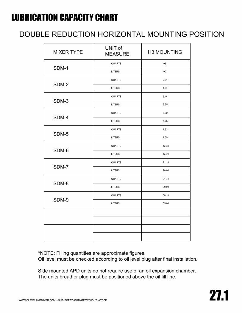
*NOTE: Filling quantities are approximate figures.Oil level must be checked according to oil level plug after final installation.
Side mounted APD units do not require use of an oil expansion chamber.The units breather plug must be positioned above the oil fill line.
55.00
58.14
LITERS
QUARTS
SDM-9
SDM-8QUARTS
LITERS
31.71
30.00
20.00
21.14
LITERS
QUARTS
SDM-7
SDM-6QUARTS
LITERS
12.68
12.00
7.50
7.93
LITERS
QUARTS
SDM-5
SDM-4QUARTS
LITERS
5.02
4.75
3.25
3.44
LITERS
QUARTS
SDM-3
SDM-2QUARTS
LITERS
2.01
1.90
H3 MOUNTINGUNIT ofMEASUREMIXER TYPE
DOUBLE REDUCTION HORIZONTAL MOUNTING POSITION
27.1
LUBRICATION CAPACITY CHART
SDM-1QUARTS
LITERS
.95
.90

LUBRICATION CAPACITY CHART
27
DOUBLE REDUCTION VERTICAL MOUNTING POSITION
MIXER TYPEUNIT ofMEASURE H5 MOUNTING
APD-1QUARTS
LITERS
1.27
1.20
2.00
2.11
LITERS
QUARTS
APD-2
APD-3QUARTS
LITERS
4.33
4.10
5.40
5.71
LITERS
QUARTS
APD-4
APD-5QUARTS
LITERS
9.30
8.80
17.50
18.50
LITERS
QUARTS
APD-6
APD-7QUARTS
LITERS
28.50
27.00
41.00
43.30
LITERS
QUARTS
APD-8
APD-9QUARTS
LITERS
76.10
72.00
90.00
95.00
LITERS
QUARTS
APD-10
APD-11QUARTS
LITERS
206.00
195.00
*NOTE: Filling quantities are approximate figures.Oil level must be checked according to oil level plug after final installation.
Vertical mounted units require use of an oil expansion chamber.The expansion chamber must be mounted to the mixer above the oil fill line.

Acceptable oil fill level is within 1/2" of the bottom of the fill plug threads.For mounting angles not shown, consult factory.
*NOTE: Filling quantities are approximate figures.Oil level must be checked according to oil level plug after final installation.
210.00
222.00
LITERS
QUARTS
APD-11
APD-10QUARTS
LITERS
93.00
88.00
74.00
78.20
LITERS
QUARTS
APD-9
APD-8QUARTS
LITERS
40.20
38.00
25.00
26.40
LITERS
QUARTS
APD-7
APD-6QUARTS
LITERS
19.00
18.00
14.00
14.80
LITERS
QUARTS
APD-5
APD-4QUARTS
LITERS
8.77
8.30
5.60
5.92
LITERS
QUARTS
APD-3
APD-2QUARTS
LITERS
3.28
3.10
-
-
LITERS
QUARTS
N/A
H5 MOUNTINGUNIT ofMEASUREMIXER TYPE
TRIPLE REDUCTION VERTICAL MOUNTING POSITION
28
LUBRICATION CAPACITY CHART
APD-12QUARTS
LITERS
222.00
210.00

SERVICE RECORDS
DATES NOTES
29