
Kyle Installation and Operation Instructions S280-79-10 · 2021. 3. 12. · Introduction Service...
56
Printed in USA Safety Information . . . . . . . . . . . . . . . . . . . . . . . . . 2 Product Information . . . . . . . . . . . . . . . . . . . . . . . . 3 Introduction . . . . . . . . . . . . . . . . . . . . . . . . . . . . . . . 3 ANSI Standards . . . . . . . . . . . . . . . . . . . . . . . . . . . 3 Quality Standards . . . . . . . . . . . . . . . . . . . . . . . . . . 3 Acceptance and Initial Inspection . . . . . . . . . . . . . . 3 Handling and Storage . . . . . . . . . . . . . . . . . . . . . . . 3 Battery Replacement . . . . . . . . . . . . . . . . . . . . . . . 3 Control Power . . . . . . . . . . . . . . . . . . . . . . . . . . . . . 3 Initializing the Control . . . . . . . . . . . . . . . . . . . . . . . 4 Form 5 Control Description . . . . . . . . . . . . . . . . . . 5 Recloser Interface (RIF) Module . . . . . . . . . . . . . . 6 Central Processing Unit (CPU) Module . . . . . . . . . 6 Discrete Interface (DIF) Module . . . . . . . . . . . . . . . 6 Power Supply Module . . . . . . . . . . . . . . . . . . . . . . . 6 Form 5 Control Operator Panel . . . . . . . . . . . . . . . 7 Battery Test Procedure . . . . . . . . . . . . . . . . . . . . . . 14 Control Features . . . . . . . . . . . . . . . . . . . . . . . . . . . 14 Communications . . . . . . . . . . . . . . . . . . . . . . . . . . . 19 Auxiliary Power for Accessories . . . . . . . . . . . . . . 20 Recloser Interface (RIF) Module Configuration . . 20 Form 5 Universal Device Protection (UDP) Control . . . . . . . . . . . . . . . . . . . . . . . . . . . . . . . . . . . 21 Form 5 DC NOVA Control . . . . . . . . . . . . . . . . . . . 22 Discrete Interface (DIF) Accessory . . . . . . . . . . . . 23 Customer Connection Information . . . . . . . . . . . . . 23 Standard and UDP DIF Module 1 Inputs . . . . . . . . 26 Standard and UDP DIF Module 1 Outputs . . . . . . . 28 Standard and UDP Module 2 Inputs . . . . . . . . . . . . 29 Standard and UDP Module 2 Outputs . . . . . . . . . . 30 Input Accuracy . . . . . . . . . . . . . . . . . . . . . . . . . . . . 31 Installation Procedure . . . . . . . . . . . . . . . . . . . . . . 32 Initial Programming Prior to Installation . . . . . . . . . 32 Control / Recloser Compatibility . . . . . . . . . . . . . . . 32 Control Cable . . . . . . . . . . . . . . . . . . . . . . . . . . . . . 32 Mounting the Control . . . . . . . . . . . . . . . . . . . . . . . 33 Grounding the Control . . . . . . . . . . . . . . . . . . . . . . 34 Customer Connections for AC Power . . . . . . . . . . . 38 Customer Connections for Metering . . . . . . . . . . . . 38 Before Placing Control and Recloser into Service . 42 Testing and Troubleshooting . . . . . . . . . . . . . . . . 43 Testing an Installed Control . . . . . . . . . . . . . . . . . . 43 Testing with Type MET Tester . . . . . . . . . . . . . . . . 43 Closing the Recloser During Testing . . . . . . . . . . . 44 Form 5 Control Default Test Procedure . . . . . . . . 47 Remove the Control from Service . . . . . . . . . . . . . 55 Return the Control to Service . . . . . . . . . . . . . . . . 55 Additional Information . . . . . . . . . . . . . . . . . . . . . . 56 1 Service Information Reclosers Kyle ® Form 5, Form 5 UDP, Form 5 DC NOVA Microprocessor-Based Recloser Controls Installation and Operation Instructions S280-79-10 November 2001 • Supersedes 1/01 Figure 1. Kyle ® Form 5/UDP microprocessor-based recloser control. 99001KM Contents Applicable to serial numbers above 3000 or beginning with CP57.
Transcript of Kyle Installation and Operation Instructions S280-79-10 · 2021. 3. 12. · Introduction Service...

Printed in USA
Safety Information . . . . . . . . . . . . . . . . . . . . . . . . . 2Product Information . . . . . . . . . . . . . . . . . . . . . . . . 3
Introduction . . . . . . . . . . . . . . . . . . . . . . . . . . . . . . . 3ANSI Standards . . . . . . . . . . . . . . . . . . . . . . . . . . . 3Quality Standards . . . . . . . . . . . . . . . . . . . . . . . . . . 3Acceptance and Initial Inspection . . . . . . . . . . . . . . 3Handling and Storage . . . . . . . . . . . . . . . . . . . . . . . 3Battery Replacement . . . . . . . . . . . . . . . . . . . . . . . 3Control Power . . . . . . . . . . . . . . . . . . . . . . . . . . . . . 3Initializing the Control . . . . . . . . . . . . . . . . . . . . . . . 4
Form 5 Control Description . . . . . . . . . . . . . . . . . . 5Recloser Interface (RIF) Module . . . . . . . . . . . . . . 6Central Processing Unit (CPU) Module . . . . . . . . . 6Discrete Interface (DIF) Module . . . . . . . . . . . . . . . 6Power Supply Module . . . . . . . . . . . . . . . . . . . . . . . 6Form 5 Control Operator Panel . . . . . . . . . . . . . . . 7Battery Test Procedure . . . . . . . . . . . . . . . . . . . . . . 14Control Features . . . . . . . . . . . . . . . . . . . . . . . . . . . 14Communications . . . . . . . . . . . . . . . . . . . . . . . . . . . 19
Auxiliary Power for Accessories . . . . . . . . . . . . . . 20Recloser Interface (RIF) Module Configuration . . 20Form 5 Universal Device Protection (UDP)Control . . . . . . . . . . . . . . . . . . . . . . . . . . . . . . . . . . . 21Form 5 DC NOVA Control . . . . . . . . . . . . . . . . . . . 22
Discrete Interface (DIF) Accessory . . . . . . . . . . . . 23Customer Connection Information . . . . . . . . . . . . . 23Standard and UDP DIF Module 1 Inputs . . . . . . . . 26Standard and UDP DIF Module 1 Outputs . . . . . . . 28Standard and UDP Module 2 Inputs . . . . . . . . . . . . 29Standard and UDP Module 2 Outputs . . . . . . . . . . 30
Input Accuracy . . . . . . . . . . . . . . . . . . . . . . . . . . . . 31Installation Procedure . . . . . . . . . . . . . . . . . . . . . . 32
Initial Programming Prior to Installation . . . . . . . . . 32Control / Recloser Compatibility . . . . . . . . . . . . . . . 32Control Cable . . . . . . . . . . . . . . . . . . . . . . . . . . . . . 32Mounting the Control . . . . . . . . . . . . . . . . . . . . . . . 33Grounding the Control . . . . . . . . . . . . . . . . . . . . . . 34Customer Connections for AC Power . . . . . . . . . . . 38Customer Connections for Metering . . . . . . . . . . . . 38Before Placing Control and Recloser into Service . 42
Testing and Troubleshooting . . . . . . . . . . . . . . . . 43Testing an Installed Control . . . . . . . . . . . . . . . . . . 43Testing with Type MET Tester . . . . . . . . . . . . . . . . 43Closing the Recloser During Testing . . . . . . . . . . . 44
Form 5 Control Default Test Procedure . . . . . . . . 47Remove the Control from Service . . . . . . . . . . . . . 55Return the Control to Service . . . . . . . . . . . . . . . . 55Additional Information . . . . . . . . . . . . . . . . . . . . . . 56
1
Service Information
ReclosersKyle® Form 5, Form 5 UDP, Form 5 DC NOVAMicroprocessor-Based Recloser ControlsInstallation and Operation Instructions S280-79-10
November 2001 • Supersedes 1/01
Figure 1.Kyle® Form 5/UDP microprocessor-based recloser control.
99001KM
Contents
Applicable to serial numbers above 3000 or beginning with CP57.

Kyle Form 5, Form 5 UDP, Form 5 DC NOVA Recloser Control Installation and Operation Instructions
2
The instructions in this manual are not intended as a sub-stitute for proper training or adequate experience in thesafe operation of the equipment described. Only compe-tent technicians who are familiar with this equipmentshould install, operate, and service it.
A competent technician has these qualifications:
• Is thoroughly familiar with these instructions.
• Is trained in industry-accepted high- and low-voltagesafe operating practices and procedures.
• Is trained and authorized to energize, de-energize,clear, and ground power distribution equipment.
• Is trained in the care and use of protective equipmentsuch as flash clothing, safety glasses, face shield,hard hat, rubber gloves, hotstick, etc.
Following is important safety information. For safe instal-lation and operation of this equipment, be sure to readand understand all cautions and warnings.
Safety InstructionsFollowing are general caution and warning statementsthat apply to this equipment. Additional statements,related to specific tasks and procedures, are locatedthroughout the manual.
SAFETY INFORMATION
SAFETY FOR LIFECooper Power Systems products meet or exceed all applicable industry standards relating to product safety. We activelypromote safe practices in the use and maintenance of our products through our service literature, instructional trainingprograms, and the continuous efforts of all Cooper Power Systems employees involved in product design, manufacture,marketing, and service.
We strongly urge that you always follow all locally approved safety procedures and safety instructions when workingaround high voltage lines and equipment and support our “Safety For Life” mission.
!SAFETYFOR LIFE
!SAFETYFOR LIFE
WARNING: This equipment is not intended toprotect human life. Follow all locally approved pro-
cedures and safety practices when installing or operat-ing this equipment. Failure to comply can result in death,severe personal injury and equipment damage.
G102.1
!
DANGER: Hazardous voltage. Contact with haz-ardous voltage will cause death or severe per-
sonal injury. Follow all locally approved safetyprocedures when working around high and low voltagelines and equipment. G103.3
!
WARNING: Before installing, operating, main-taining, or testing this equipment, carefully read
and understand the contents of this manual. Improperoperation, handling or maintenance can result in death,severe personal injury, and equipment damage. G101.0
!
This manual may contain four types of hazardstatements:
DANGER: Indicates an imminently haz-ardous situation which, if not avoided, will
result in death or serious injury.
WARNING: Indicates a potentially hazardoussituation which, if not avoided, could result in
death or serious injury.
CAUTION: Indicates a potentially hazardoussituation which, if not avoided, may result in
minor or moderate injury.
CAUTION: Indicates a potentially hazardous situ-ation which, if not avoided, may result in equip-ment damage only.
!
!
Hazard Statement Definitions
!
WARNING: Power distribution equipment mustbe properly selected for the intended application. It
must be installed and serviced by competent personnelwho have been trained and understand proper safetyprocedures. These instructions are written for such per-sonnel and are not a substitute for adequate trainingand experience in safety procedures. Failure to properlyselect, install, or maintain power distribution equipmentcan result in death, severe personal injury, and equip-ment damage. G122.2
!

IntroductionService Information S280-79-10 provides installation andoperation instructions for the Kyle Form 5 and Form 5UDP microprocessor-based electronic recloser controls.
Read This Manual FirstRead and understand the contents of this manual and fol-low all locally approved procedures and safety practicesbefore installing or operating this equipment.
Additional InformationThese instructions cannot cover all details or variations inthe equipment, procedures, or process described, norprovide directions for meeting every possible contingencyduring installation, operation, or maintenance. Whenadditional information is desired to satisfy a problem notcovered sufficiently for the user's purpose, please contactyour Cooper Power Systems sales representative.
ANSI StandardsKyle reclosers are designed and tested in accordancewith the following ANSI standards: C37.60 and C37.85and ANSI Guide C37.61.
Quality StandardsISO 9001:2000-Certified Quality Management System
Acceptance andInitial InspectionEach Form 5 control is completely assembled, tested, andinspected at the factory. It is carefully calibrated, adjustedand in good condition when accepted by the carrier forshipment.
Upon receipt, inspect the carton for signs of damage.Unpack the control and inspect it thoroughly for damageincurred during shipment. If damage is discovered, file aclaim with the carrier immediately.
Handling and StorageBe careful during handling and storage of the control to min-imize the possibility of damage. If the control is to be storedfor any length of time prior to installation, provide a clean,dry storage area. If storage is in a humid atmosphere, makeprovisions to keep the control circuitry energized.
Note: To energize the control, apply AC power to the AC sup-ply input connector block TB1 located left of theRecloser Interface (RIF) module within the control.Refer to the Customer Connection for AC power sec-tion in this manual.
Control Battery Storage and ChargingThe 24 Vdc control battery in the Form 5 control is fullycharged prior to shipment and is ready for use. In order tomaintain sufficient charge to operate the control, thesealed lead acid battery should be charged after no morethan three months of storage.
Note: Two 12 Vdc, 13 amp-hour batteries are available foruse with the Form 5 Distribution Automation upgradeaccessory.
Temperature has an effect on battery life. Sealed leadacid batteries should be stored, fully charged, at roomtemperature. Never store lead acid batteries at tempera-ture exceeding 47°C (117°F), as damage can result inapproximately one month.
To keep the battery charged, energize the control’s built-in charger with AC power applied to the user AC supplyinput connector block TB1, located left of the RIF modulewithin the control cabinet.
Note: When shipped from the factory, the battery source isdisconnected and its output plugs are taped to the cab-inet. Connect the battery plugs into the mating connec-tors to complete the battery circuit.
Battery ReplacementThe 24 Vdc control battery has a life expectancy of 4 to 6years. It is recommended that the battery be replacedafter 4 years.
Control PowerThe primary source of power is factory configured for 120 Vacor 240 Vac. The 240 Vac version is available as an optionat time of order entry. Primary power is rectified to chargethe power capacitor and to power the dc/dc converter thatprovides power to the control. A minimum of 500 mA of accurrent is required for heater operation, battery chargingcurrent, and to keep all modules energized.
S280-79-10
3
!SAFETYFOR LIFE
PRODUCT INFORMATION
IMPORTANT: Connect the control battery when ACpower is connected to the control’s AC supply Input Ter-minal Block. The battery must be disconnected prior toshipping or storing the control.
IMPORTANT: To maintain sufficient charge to oper-ate the control and prevent battery cell damage, thesealed lead-acid batteries should be charged after nomore than three months of storage.
AC ReclosersPower to operate the tripping and closing solenoids in therecloser is provided by the power capacitor locatedbehind the operator panel of the control. A sealed, 24-volt,lead acid battery is located in the lower portion of the con-trol cabinet and is utilized to provide operating and trip-ping energy when AC power is temporarily lost. Thecontrol is equipped with an ac-powered, temperature-compensated battery charger.
Operation Upon Loss Of AC PowerIf the control is equipped with the standard 24 Vdc lead-acid battery, the control maintains full operation from thebattery power supply for a minimum of 32 hours at 20°C(24 hours at -40°C). To prevent battery damage, the con-trol shuts down automatically upon detection of low bat-tery voltage below 22.7 Vdc.
Control programming settings and parameters—includingevent recorder, duty monitor, and data profile meteringparameters—are stored in non-volatile memory andretained upon loss of control power. The time/date clockresets to 0:00:00, 1970 upon loss of control power.
The AC power LED indicator on the operator panel of thecontrol will turn off after 15 seconds upon loss of ACpower. The indicator will illuminate immediately uponreturn of ac power.
Initializing the ControlTwo methods are available to initialize the Form 5 control.
Method 1: Connect AC power to the input connector ter-minal TB-1. Refer to the Customer Connec-tions for AC Power section of this manual.
Method 2: Connect the battery terminal on the controland press the MANUAL BATTERY RECON-NECT button located on the Form 5 powersupply. See Figure 4.
Note: Method 2 powers the control off the batteryand is not intended for long term operation.
In both methods, after initialization, set the control clockvia the interface software.
Kyle Form 5, Form 5 UDP, Form 5 DC NOVA Recloser Control Installation and Operation Instructions
4
CONTROL OK
AC POWER
ABOVE MIN TRIP
REVERSE POWER FLOW
RECLOSER MALFUNCTION
CHECK BATTERY
BUSHINGS 1-2 FAULT TARGET
BUSHINGS 3-4 FAULT TARGET
BUSHINGS 5-6 FAULT TARGET
GROUND FAULT TARGET
SENSITIVE-GROUND FAULT TARGET
BUSHINGS 1-2 VOLTAGE
BUSHINGS 3-4 VOLTAGE
BUSHINGS 5-6 VOLTAGE
RECLOSER CLOSED
RECLOSER OPEN
CONTROL LOCKOUT
BACK NEXT
LAMPTEST
CHANGERESET
TARGETS
RESETMAX CURRENT
GND TRIPBLOCKED
NONRECLOSING
SUPERVISORYBLOCKED
COLD LOADPICK UP
BLOCKED
BATTERYTEST
FASTTRIPS
DISABLED
ALTERNATEPROFILE
NO. 1
ALTERNATEPROFILE
NO. 2
ALTERNATEPROFILE
NO. 3
HOT LINETAG
ON
OFF
TX 3
RX 3
CLOSETRIP(LOCKOUT) KYLE®
FORM 5RECLOSER CONTROL
RS232
TX 2
RX 2
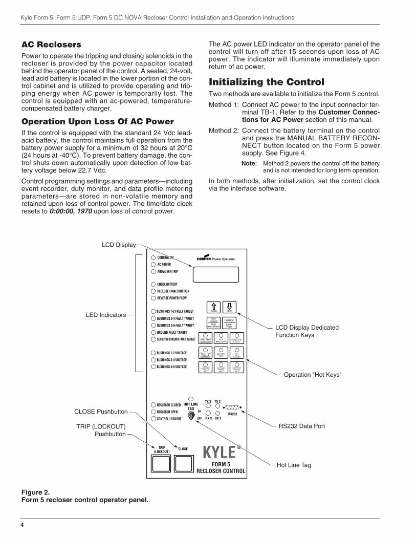
LED Indicators
LCD Display
TRIP (LOCKOUT)Pushbutton
CLOSE Pushbutton
LCD Display DedicatedFunction Keys
Operation "Hot Keys"
RS232 Data Port
Hot Line Tag
Figure 2. 99005KM
Form 5 recloser control operator panel.

Current sensing is provided by three current transformerslocated in the recloser and interfaced to the Form 5 controlvia the control cable. This cable also supplies Trip, Close,and Recloser status, and connects to the Recloser Inter-face (RIF) module to provide isolation for reliable opera-tion. Voltages for metering are also connected to the RIFmodule via the connector terminal block, TB-1 (Figure 3).
A functional block diagram of the Form 5 control is shownin Figure 3. Line current flowing through the recloser isconverted by the CPU module to a digital signal suitablefor metering and fault current calculations. Data samplingoccurs at a rate 32 times per cycle. The CPU contains adata acquisition section that uses the acquired samples tocompute the fundamental currents and voltage for use inovercurrent, under/over voltage and under/over frequencyprotection, as well as currents and voltages for meteringfunctions. The current for overcurrent protection is calcu-lated on a sub-cycle basis; it includes only the fundamen-tal and DC component. For metering, the fundamental andharmonic current and voltages are determined.
When the phase or ground current exceeds its pro-grammed minimum-trip value and associated time-cur-rent curve (TCC) t iming, the control init iates theprogrammed sequence of recloser tripping and reclosingoperations via the CPU and RIF modules. If the fault istemporary, the control ceases to command recloser oper-ations after a successful reclose, and the control resets tothe start of its operating sequence after a preset timedelay. If the fault is permanent, the control performs itscomplete programmed sequence of reclose commandsand locks out with the recloser open. Once locked out, thecontrol must be closed via the operator panel or SCADAcommunications. This resets the control to the start of theoperating sequence.
The following chain of events occurs for an operatingsequence of two trips to lockout:
1. The overcurrent signal is integrated with time on theselected curve for the first trip operation (TCC1) toproduce the signal which energizes the trip circuit.
2. Energizing the trip circuit connects the battery andcapacitor to the trip solenoid to open the recloser.
3. Upon opening, the control starts timing on the firstreclosing interval-delay time.
4. Upon expiration of this reclosing interval-delay, a clos-ing signal is issued from the control, closing therecloser and selecting the time-current characteristicsfor the second trip operation (TCC2).
5. If current remains above the minimum-trip level, thetripping and reclosing sequence is repeated.
6. The control begins the reset-delay timer if the over-current is cleared before the operating sequencereaches lockout indicated by a closed recloser andcurrent below minimum trip.
7. When the reset-delay times out, the control is reset tothe home state and is ready for another programmedoperating sequence. If current rises above minimumtrip prior to the reset-delay timing out, the timer ishalted and the control resumes the operatingsequence while the accumulated reset-delay timing isrestarted.
S280-79-10
5
!SAFETYFOR LIFE
Figure 3.Form 5 control operational flow diagram.
FORM 5 CONTROL DESCRIPTION
BATTERY
TRIP SOLENOID
CLOSE SOLENOID
A Ø CT
B Ø CT
C Ø CT
OPEN / CLOSESWITCHES
CT COMMON
RECLOSER RIF
OPTICALISOLATION
OPTICALISOLATIONOPTICAL
ISOLATION
OPTICALISOLATION
MATCHINGTRANSFORMERS
AND SIGNALCONDITIONING
TB1 TERMINAL BLOCK
CUSTOMER P.T. INPUTS POWER SUPPLY
CPU
RS232Or
FIBER-OPTICPORT
RS232Or
FIBER-OPTICPCB
OPTIONS
OPERATOR'SPANEL
KEYBOARDLED'sLCD
RS232 PORT
DIF#1(OPTIONAL)
DIF#2(OPTIONAL)
USERCONNECTIONS
6 unlatched outputs6 latched outputs
12 inputs
1212
USERCONNECTIONS
6 unlatched outputs6 latched outputs
12 inputs
1212
The Form 5 control is constructed in a modular fashion tosimplify service and the addition of accessories (Figure4). The standard configuration incorporates a CentralProcessing Unit (CPU) module, power supply module,Recloser Interface (RIF) module, and an operator panel.
Discrete Interface (DIF) module(s), the fiber-optic boardand the RS-232 communication interface cards may beordered as accessories. Mounting provisions can beprovided to add customer-supplied radio and modemmodules.
Recloser Interface (RIF) ModuleThe Recloser Interface (RIF) Module provides the inter-face between the recloser and the CPU module, as wellas the interface between the voltage sensors and theCPU module. The RIF is designed to interface with the fol-lowing reclosers: WE/WVE group, NOVA group,VSA/VSO group, and KFME/KFVME (50Hz) group.
The recloser connector includes three current-trans-former inputs, Open and Closed status sensing, and Tripand Close controls. The voltage sensor connectoraccepts six voltage inputs; three for source-side, andthree for load-side voltage. Two sets of dip switches,located on the RIF front panel, utilize different switch posi-tions to configure the desired voltage. See Figure 17.
The RIF board accepts either 12, 120, or 240 Vac voltageinputs for metering. The factory configuration is outlinedon the module label and can be customized to user spec-ification. See RECLOSER INTERFACE (RIF) MODULECONFIGURATION section of this manual.
Central Processing Unit (CPU)ModuleThe CPU module is the center of the Form 5 control. TheCPU contains a 32-bit micro-controller, a Digital SignalProcessor, RAM and EEPROM memory, and a 16-bitanalog-to-digital converter. The CPU module accepts 16analog inputs which it routes through the digital signalprocessor, which samples 32 times per cycle, to computeharmonic analysis to the 15th harmonic.
Discrete Interface (DIF) ModuleThe Discrete Interface (DIF) module allows users withexisting RTUs the ability to interface with the Form 5 con-trol. The DIF module contains 12 inputs and 12 outputscan be customized for a remote or supervisory function.One Form 5 control can accommodate two DIF modules.See DISCRETE INTERFACE (DIF) ACCESSORY sec-tion of this manual.
Power Supply ModuleThe Power Supply module is designed to accept 100 to134 Vac or 200 to 268 Vac user-supplied input power ateither 50 or 60 Hz.
The Power supply module (connection P9) provides aux-iliary power to radio communications units, RTUs andother accessories. The auxiliary output provides 24 Vdc(12 Vdc is available) for user loads. The auxiliary powersupply has the capability to provide a load of up to 40 Wpeak (1 second) and 3 W average. The auxiliary power isfused and current-limited to prevent user loads from dis-abling the control.
Kyle Form 5, Form 5 UDP, Form 5 DC NOVA Recloser Control Installation and Operation Instructions
6
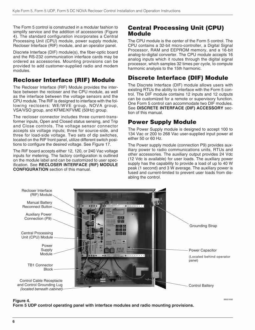
Figure 4.Form 5 UDP control operating panel with interface modules and radio mounting provisions.
99001KM
Control Cable Receptacleand Control Grounding Lug
(located beneath cabinet)Control Battery
Central ProcessingUnit (CPU) Module
Recloser Interface(RIF) Module
TB1 ConnectorBlock
PowerSupplyModule
Power Capacitor
(Located behind operatorpanel)
Grounding Strap
Manual BatteryReconnect Button
Auxiliary PowerConnection (P9)
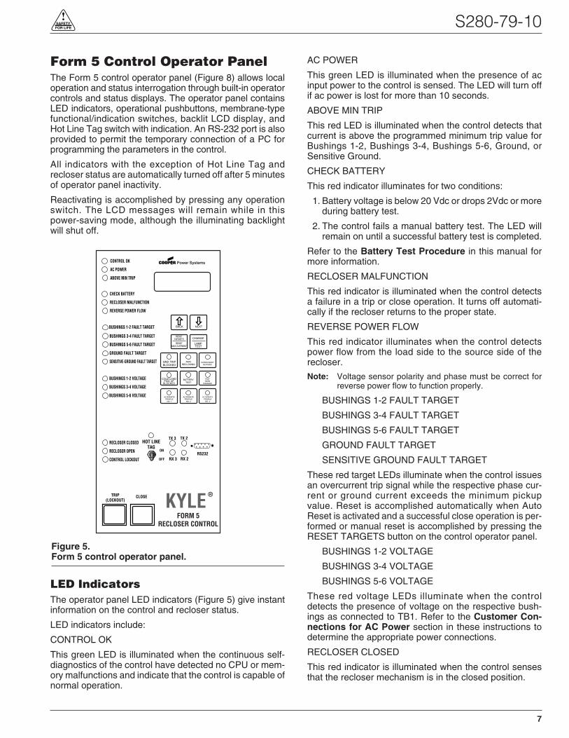
Form 5 Control Operator PanelThe Form 5 control operator panel (Figure 8) allows localoperation and status interrogation through built-in operatorcontrols and status displays. The operator panel containsLED indicators, operational pushbuttons, membrane-typefunctional/indication switches, backlit LCD display, andHot Line Tag switch with indication. An RS-232 port is alsoprovided to permit the temporary connection of a PC forprogramming the parameters in the control.
All indicators with the exception of Hot Line Tag andrecloser status are automatically turned off after 5 minutesof operator panel inactivity.
Reactivating is accomplished by pressing any operationswitch. The LCD messages will remain while in thispower-saving mode, although the illuminating backlightwill shut off.
LED IndicatorsThe operator panel LED indicators (Figure 5) give instantinformation on the control and recloser status.
LED indicators include:
CONTROL OK
This green LED is illuminated when the continuous self-diagnostics of the control have detected no CPU or mem-ory malfunctions and indicate that the control is capable ofnormal operation.
AC POWER
This green LED is illuminated when the presence of acinput power to the control is sensed. The LED will turn offif ac power is lost for more than 10 seconds.
ABOVE MIN TRIP
This red LED is illuminated when the control detects thatcurrent is above the programmed minimum trip value forBushings 1-2, Bushings 3-4, Bushings 5-6, Ground, orSensitive Ground.
CHECK BATTERY
This red indicator illuminates for two conditions:
1. Battery voltage is below 20 Vdc or drops 2Vdc or moreduring battery test.
2. The control fails a manual battery test. The LED willremain on until a successful battery test is completed.
Refer to the Battery Test Procedure in this manual formore information.
RECLOSER MALFUNCTION
This red indicator is illuminated when the control detectsa failure in a trip or close operation. It turns off automati-cally if the recloser returns to the proper state.
REVERSE POWER FLOW
This red indicator illuminates when the control detectspower flow from the load side to the source side of therecloser.
Note: Voltage sensor polarity and phase must be correct forreverse power flow to function properly.
BUSHINGS 1-2 FAULT TARGET
BUSHINGS 3-4 FAULT TARGET
BUSHINGS 5-6 FAULT TARGET
GROUND FAULT TARGET
SENSITIVE GROUND FAULT TARGET
These red target LEDs illuminate when the control issuesan overcurrent trip signal while the respective phase cur-rent or ground current exceeds the minimum pickupvalue. Reset is accomplished automatically when AutoReset is activated and a successful close operation is per-formed or manual reset is accomplished by pressing theRESET TARGETS button on the control operator panel.
BUSHINGS 1-2 VOLTAGE
BUSHINGS 3-4 VOLTAGE
BUSHINGS 5-6 VOLTAGE
These red voltage LEDs illuminate when the controldetects the presence of voltage on the respective bush-ings as connected to TB1. Refer to the Customer Con-nections for AC Power section in these instructions todetermine the appropriate power connections.
RECLOSER CLOSED
This red indicator is illuminated when the control sensesthat the recloser mechanism is in the closed position.
S280-79-10
7
!SAFETYFOR LIFE
Figure 5.Form 5 control operator panel.
CONTROL OK
AC POWER
ABOVE MIN TRIP
REVERSE POWER FLOW
RECLOSER MALFUNCTION
CHECK BATTERY
BUSHINGS 1-2 FAULT TARGET
BUSHINGS 3-4 FAULT TARGET
BUSHINGS 5-6 FAULT TARGET
GROUND FAULT TARGET
SENSITIVE-GROUND FAULT TARGET
BUSHINGS 1-2 VOLTAGE
BUSHINGS 3-4 VOLTAGE
BUSHINGS 5-6 VOLTAGE
RECLOSER CLOSED
RECLOSER OPEN
CONTROL LOCKOUT
BACK NEXT
LAMPTEST
CHANGERESET
TARGETS
RESETMAX CURRENT
GND TRIPBLOCKED
NONRECLOSING
SUPERVISORYBLOCKED
COLD LOADPICK UP
BLOCKED
BATTERYTEST
FASTTRIPS
DISABLED
ALTERNATEPROFILE
NO. 1
ALTERNATEPROFILE
NO. 2
ALTERNATEPROFILE
NO. 3
HOT LINETAG
ON
OFF
TX 3
RX 3
CLOSETRIP(LOCKOUT) KYLE®
FORM 5RECLOSER CONTROL
RS232
TX 2
RX 2

RECLOSER OPEN
This green indicator is illuminated when the control sensesthat the recloser mechanism is in the open position.
CONTROL LOCKOUT
This green indicator is illuminated when the recloser isopen and a reclosing sequence is not in progress or whenthe lockout handle on the recloser mechanism is in thedown position; i.e., trip and close circuits are open.
Note: The RECLOSER MALFUNCTION, RECLOSER OPEN,RECLOSER CLOSED, and RECLOSER LOCKOUTLEDs will flash upon detection of a trip failure. See theControl Features section of this manual.
TRIP (Lockout) PushbuttonThe TRIP pushbutton (Figure 2) provides front-panelaccess to trip (lockout) the recloser. When pressed, theTRIP push-button opens the recloser and locks out thecontrol.
CLOSE PushbuttonWhen pressed, the CLOSE pushbutton (Figure 2) returnsthe control to the initial or home position, closing therecloser. The control is ready for the start of a newtrip/close sequence.
Note: Pressing the CLOSE pushbutton from the Lockout posi-tion, will initiate Cold Load Pickup (CLPU) protection, ifthe feature is first enabled from the interface softwareProtection Profile screen, and the COLD LOAD PICKUPBLOCKED LED on the operator panel is not lit.
If the recloser is closed, pushing the CLOSE pushbuttonhas no effect on the control. Depressing and holding theCLOSE pushbutton does not activate the Cold LoadPickup feature. See Cold Load Pickup in the ControlFeatures section of this manual.
The Form 5 control has a Manual Close Delay feature thatprovides an interval of time from when the CLOSE push-button is depressed to the time when manual close oper-ation is performed. See Manual Close Delay in theControl Features section of this manual.
LCD DisplayThe control operator panel has a large, backlit LCD dis-play (Figure 6) used for viewing control parameters andmonitoring system conditions. Data is organized intoscreens of information, with each display containing fourlines of information, with up to 20 characters per line.Access to the screens is obtained through navigationalkeys which permit the user to scroll through the menu in atimely and efficient manner.
When an overcurrent trip occurs, the control automaticallydisplays the fault current values as shown on the LCD dis-play as Screen 1. Refer to LCD Display Screens sectionof this manual.
NEXT KeyPressing the NEXT key causes the LCD display to scroll tothe next screen of available information. Pressing and hold-ing the NEXT key causes the control to scroll to subsequentscreens at the rate of about two screens per second.
BACK KeyPressing the BACK key causes the LCD display to scrollto the previous screen of available information. Pressingand holding the BACK key causes the control to scroll toprevious screen.
RESET TARGETS/RESET MAXCURRENT KeyPressing the RESET TARGETS/RESET MAX CURRENTkey resets the fault target indicators on the control opera-tor panel. The fault current values shown on Screen 2 ofthe LCD display will reset to values of zero.
Pressing and holding the RESET TARGETS/RESETMAX CURRENT key for three seconds will reset the min-imum and maximum current and histogram values in LCDDisplay screens 34 through 37. This key will also reset theTrip Failure Detection feature. See the Control Featuressection of this manual.
CHANGE/LAMP TEST KeyPressing this key for less than three seconds places thecontrol into a CHANGE mode for 10 seconds as indicatedby the LCD display. CHANGE mode permits the user tochange the state of the nine function/indicator switches onthe operator panel. Security is enhanced by permitting aonly one selection for each CHANGE mode period.
Pressing and holding the CHANGE/LAMP TEST key forthree seconds will cause the control to perform a front-panel lamp test. In the Lamp Test Mode, the status indi-cators flash three times (one second on, one second off).All status indicators then return to their previous state.While in the Lamp Test Mode, the control response tooperator panel keys is disabled, except for the TRIP(LOCKOUT), CLOSE, and HOT LINE TAG switches.
Kyle Form 5, Form 5 UDP, Form 5 DC NOVA Recloser Control Installation and Operation Instructions
8
Figure 6.LCD display and dedicated function keys.
NEXT BACK
RESETTARGETS
CHANGE
LAMPTEST
RESETMAX CURRENT

LCD Display ScreensEvery LCD display screen contains a parameter name,parameter value, and parameter units. If the controldetects that a parameter value is invalid, the LCD displayshows five dash characters (- - - - -) in the value field of thescreen. Demand metered values are indicated by (D) andinstantaneous values by (I).
S280-79-10
9
!SAFETYFOR LIFE
1 Gnd ____________ A
Ph1-2 ____________ A
Ph3-4 ____________ A
Ph5-6 ____________ A
2 Gnd Fault ____________ A
Ph1-2 Fault ____________ A
Ph3-4 Fault ____________ A
Ph5-6 Fault ____________ A
3 Freq Trip____________ Hz
Time Date
Present Freq ____________ Hz
4 Ph1-N VTrip ____________ V
Ph3-N VTrip ____________ V
Ph5-N VTrip ____________ V
Time Date
5 Tot ____________ kWh
Ph1-2 ____________ kWh
Ph3-4 ____________ kWh
Ph5-6 ____________ kWh
6 Instant S1 Ph-N
Ph1-N ____________ V
Ph3-N ____________ V
Ph5-N ____________ V
7 Instant S1 Ph-Ph
Ph1-3 ____________ V
Ph3-5 ____________ V
Ph5-1 ____________ V
8 Instant S2 Ph-N
Ph2-N ____________ V
Ph4-N ____________ V
Ph6-N ____________ V
9 Instant S2 Ph-Ph
Ph2-4 ____________ V
Ph4-6 ____________ V
Ph6-2 ____________ V
Screen 1 – Instantaneous Load Current
Screen 1 displays line current values present for the lastovercurrent trip operation. Values are reset to zero whenthe fault targets are reset.
Screen 2 – Fault Targets
Screen 3 – Frequency Trip
Screen 4 – Voltage Trip
Screen 8 – S2 Phase-to-Neutral, Instant. Voltage
Screen 5 – Power kWh
Screen 6 – S1 Phase-to-Neutral, Instant. Voltage
Screen 9 – S2 Phase-to-Phase, Instant. Voltage
Screen 7 – S1 Phase-to-Phase, Instant. Voltage
11 Tot ____________ kW
Ph1-2 ____________ kW
Ph3-4 ____________ kW
Ph5-6 ____________ kW
Screen 11 – Real Power
10 Instant S1-S2
Ph1-2 Dif ____________ V
Ph3-4 Dif ____________ V
Ph5-6 Dif ____________ V
Screen 10 – Instantaneous Voltage
12 Tot ____________ kVA
Ph1-2 ____________ kVA
Ph3-4 ____________ kVA
Ph5-6 ____________ kVA
Screen 12 – Instantaneous kVA

Kyle Form 5, Form 5 UDP, Form 5 DC NOVA Recloser Control Installation and Operation Instructions
10
14 Tot ____________ PF
Ph1-2 ____________ PF
Ph3-4 ____________ PF
Ph5-6 ____________ PF
15 Gnd ____________ %THDI
Ph1-2 ____________ %THDI
Ph3-4 ____________ %THDI
Ph5-6 ____________ %THDI
16 Instant S1 Ph-N
Ph1-N ____________ %THDV
Ph3-N ____________ %THDV
Ph5-N ____________ %THDV
17 Demand S1 Ph-N
Ph1-N(d) ____________ V
Ph3-N(d) ____________ V
Ph5-N(d) ____________ V
19 Demand S2 Ph-N
Ph2-N(d) ____________ V
Ph4-N(d) ____________ V
Ph6-N(d) ____________ V
20 Demand S2 Ph-Ph
Ph2-4(d) ____________ V
Ph4-6(d) ____________ V
Ph6-2(d) ____________ V
13 Tot ____________ kVAr
Ph1-2 ____________ kVAr
Ph3-4 ____________ kVAr
Ph5-6 ____________ kVAr
Screen 17 – Demand Phase to Neutral Voltage
Screen 18 – Demand Phase-to-Phase Voltage
Screen 19 – Demand Phase-to-Neutral VoltageScreen 13 – Instantaneous kVAR
Screen 20 – Demand Phase-to-Phase VoltageScreen 14 – Instantaneous Power Factor
Screen 15 – Instantaneous Total Harmonic DistortionCurrent
Screen 16 – Instantaneous Total Harmonic DistortionVoltage
21 Demand S1-S2
Ph1-2(d) ____________ V
Ph3-4(d) ____________ V
Ph5-6(d) ____________ V
Screen 21 – Demand Voltage
18 Demand S1 Ph-Ph
Ph1-3 (d) ____________ V
Ph3-5(d) ____________ V
Ph5-1(d) ____________ V
22 Gnd ____________ A
Ph1-2 (d) ____________ A
Ph3-4 (d) ____________ A
Ph5-6 (d) ____________ A
23 Tot (d) ____________ kW
Ph1-2(d) ____________ kW
Ph3-4 (d) ____________ kW
Ph5-6 (d) ____________ kW
24 Tot ____________ kVA
Ph1-2(d) ____________ kVA
Ph3-4(d) ____________ kVA
Ph5-6(d) ____________ kVA
Screen 22 – Demand Current
Screen 23 – Demand kW
Screen 24 – Demand kVA
S280-79-10
11
!SAFETYFOR LIFE
25 Tot ____________ kVAr
Ph1-2(d) ____________ kVAr
Ph3-4(d) ____________ kVAr
Ph5-6(d) ____________ kVAr
26 Tot ____________ PF
Ph1-2(d) ____________ PF
Ph3-4(d) ____________ PF
Ph5-6(d) ____________ PF
27 Gnd ____________ %THDI
Ph1-2(d) ____________ %THDI
Ph3-4(d) ____________ %THDI
Ph5-6(d) ____________ %THDI
28 Demand S1 Ph-N
Ph1-N(d) ____________ %THDV
Ph3-N(d) ____________ %THDV
Ph5-N(d) ____________ %THDV
29 Gnd OC Trip ____________
Ph1-2 OC Trip ____________
Ph3-4 OCTrip ____________
Ph5-6 OC Trip ____________
30 SGF OC Trip ______
Operations ______
31 Battery Monitor
Normal _______ V
Normal _____ mA
Test _______ V
32 – Phase MT ______ A
ALT1 MT ______ A
ALT2 MT ______ A
ALT3 MT ______ A
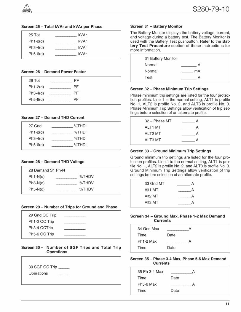
Screen 25 – Total kVAr and kVAr per Phase
Screen 26 – Demand Power Factor
Screen 27 – Demand THD Current
Screen 28 – Demand THD Voltage
Screen 29 – Number of Trips for Ground and Phase
Screen 30 – Number of SGF Trips and Total TripOperations
Screen 31 – Battery Monitor
The Battery Monitor displays the battery voltage, current,and voltage during a battery test. The Battery Monitor isused with the Battery Test pushbutton. Refer to the Bat-tery Test Procedure section of these instructions formore information.
Screen 32 – Phase Minimum Trip Settings
Phase minimum trip settings are listed for the four protec-tion profiles. Line 1 is the normal setting, ALT1 is profileNo. 1, ALT2 is profile No. 2, and ALT3 is profile No. 3.Phase Minimum Trip Settings allow verification of trip set-tings before selection of an alternate profile.
33 Gnd MT ______ A
Alt1 MT _______ A
Alt2 MT ______ A
Alt3 MT _______ A
Screen 33 – Ground Minimum Trip Settings
Ground minimum trip settings are listed for the four pro-tection profiles. Line 1 is the normal setting, ALT1 is pro-file No. 1, ALT2 is profile No. 2, and ALT3 is profile No. 3.Ground Minimum Trip Settings allow verification of tripsettings before selection of an alternate profile.
34 Gnd Max ____________A
Time Date
Ph1-2 Max ____________A
Time Date
Screen 34 – Ground Max, Phase 1-2 Max DemandCurrents
35 Ph 3-4 Max ____________A
Time Date
Ph5-6 Max ____________A
Time Date
Screen 35 – Phase 3-4 Max, Phase 5-6 Max DemandCurrents

Operation/Indication PushbuttonsNine frequently used features are provided on the controloperator panel (Figure 7).
Note: These features are activated from the keypad, controlinterface software or SCADA signal.
To initiate an operation from the operator panel, press theCHANGE/LAMP TEST key to enter the CHANGE mode.The operator has 10 seconds to select an operation andmodify settings. If no changes are made, the control willreturn to its operational state prior to entering theCHANGE mode. This prevents accidental changing ofsettings.
Red LEDs located on each switch indicate the status ofthe function, regardless of local or remote activation. Forexample, if Cold Load Pickup was activated from aSCADA signal, the red indicator would illuminate eventhough it was not activated from the operator panel.
Note: Operation LEDs activated from local or remote sourcesdo not illuminate when the front panel is in the power-save mode.
GND TRIP BLOCKED
Ground Trip Blocked is activated by pressing theCHANGE/LAMP TEST key, then pressing the GND TRIPBLOCKED key. The red indicator illuminates.
Kyle Form 5, Form 5 UDP, Form 5 DC NOVA Recloser Control Installation and Operation Instructions
12
GND TRIPBLOCKED
NONRECLOSING
SUPERVISORYBLOCKED
COLD LOADPICKUP
BLOCKED
BATTERYTEST
FASTTRIPS
DISABLED
ALTERNATEPROFILE
NO. 1
ALTERNATEPROFILE
NO. 2
ALTERNATEPROFILE
NO. 3
Figure 7.Operation/indication pushbuttons.
37 Ph3-4 Min ____________A
Time Date
Ph5-6 Min ____________A
Time Date
40 – Comm Port 2 ______
Protocol _______
Speed _______
Address _______
41 – Comm Port 3 ______
Protocol _______
Speed _______
Address _______
38 Fault Location
Distance ____________miles
<Control Identification>
Time Date
39 CPU Firmware X.XX
Firmware FW Database X
<Control Identification>
Time Date
Screen 38 – Fault Location
Screen 39 – Control Information
Screen 40 – Communication Port 2 Settings
This message displays the protocol settings (2179 orDNP3.0), baud rate, and address for Serial Port #2.Baud rate and address are set using the interface soft-ware, while protocol is set at the factory based on user’sspecifications.
Screen 37 – Phase 3-4 Min, Phase 5-6 Min Currents
Screen 41 – Communication Port 3 Settings
This message displays the protocol settings (2179 orDNP3.0), baud rate, and address for Serial Port #3.Baud rate and address are set using the interface soft-ware, while protocol is set at the factory based on user’sspecifications.
Note: Pressing and holding the RESET TARGETS/RESETMAX CURRENT key for three seconds will reset theminimum and maximum Demand values.
36 Gnd Min ____________A
Time Date
Ph1-2 Min ____________A
Time Date
Screen 36 – Ground Min, Phase 1-2 Min DemandCurrents
Note: Demand currents are a time integrated value and do notreflect minimum or maximum instantaneous currents.The demand integration time constant is set via the inter-face software demand metering screen. These are thesame values displayed in the histogram screen.
NON RECLOSING
Non-reclosing mode disables any automatic reclosingoperations. Non-reclosing does not alter the active TCC.The feature is activated by pressing the CHANGE/LAMPTEST key, then pressing the NON RECLOSING key. Thered indicator illuminates.
SUPERVISORY BLOCKED
Supervisory Blocked disables supervisory SCADA and theinterface software; remote SCADA remains active. Opera-tional data and metering information are available whilethe control is in the SUPERVISORY BLOCKED position.The TRIP and CLOSE pushbuttons are active indepen-dently of the SUPERVISORY BLOCKED function.
Activation of the feature is restricted to the operator panelkeypad by pressing the CHANGE/LAMP TEST key, thenpressing the SUPERVISORY BLOCKED key.
COLD LOAD PICKUP BLOCKED
The Cold Load Pickup feature is blocked while the COLDLOAD PICKUP BLOCKED is active. When CLPU is notblocked, the control utilizes the Cold Load Pickup TCC,reclose interval, operations to lockout and minimum trip set-tings in lieu of the normal first operation protection settings.
Note: The Cold Load Pickup Blocked key is replaced by the SEN-SITIVE GROUND FAULT key on international controls.
BATTERY TEST
Depressing the BATTERY TEST key performs a controlbattery test. The red indicator illuminates and turns offautomatically when the control has finished performing thetest. Refer to the Battery Test Procedure section of theseinstructions for further details on testing the control battery.
FAST TRIPS DISABLED
Fast Trips Disabled commands the control to use the pro-grammed Fast Trips Disabled time-current curve for alltripping operations.
ALTERNATE PROFILE Indicator/Key
The control has four separate protection profiles; a normalprofile, and Alternate Profiles 1, 2, and 3. Each profilechanges all protection parameters for the control. Except forthe normal profile, each has an indication and selection key.During control operation, if the three alternate profile indica-tor lights are not illuminated, the normal profile is active.
To select an alternate profile, press the CHANGE/LAMPTEST key, then press the desired alternate profile. Toreturn to the normal profile, simply turn off the active alter-nate profile. These functions can also be operatedremotely via communications interfaces.Note: Program all protection profiles. Program unused alter-
nate profiles should be programmed with the same set-ting as one of the applicable profiles. Default settings onunused alternate profiles can cause unnecessary out-ages if they are below normal system requirements.
Note: The minimum trip values for each protection profile areshown on Screens 32 and 33 of the LCD display. Checkthese minimum trip values prior to changing an alternateprofile to avoid misoperation of the control under loadconditions.
Note: On Form 5 UDP controls, Alternate Profile 3 is replacedwith SWITCH MODE.
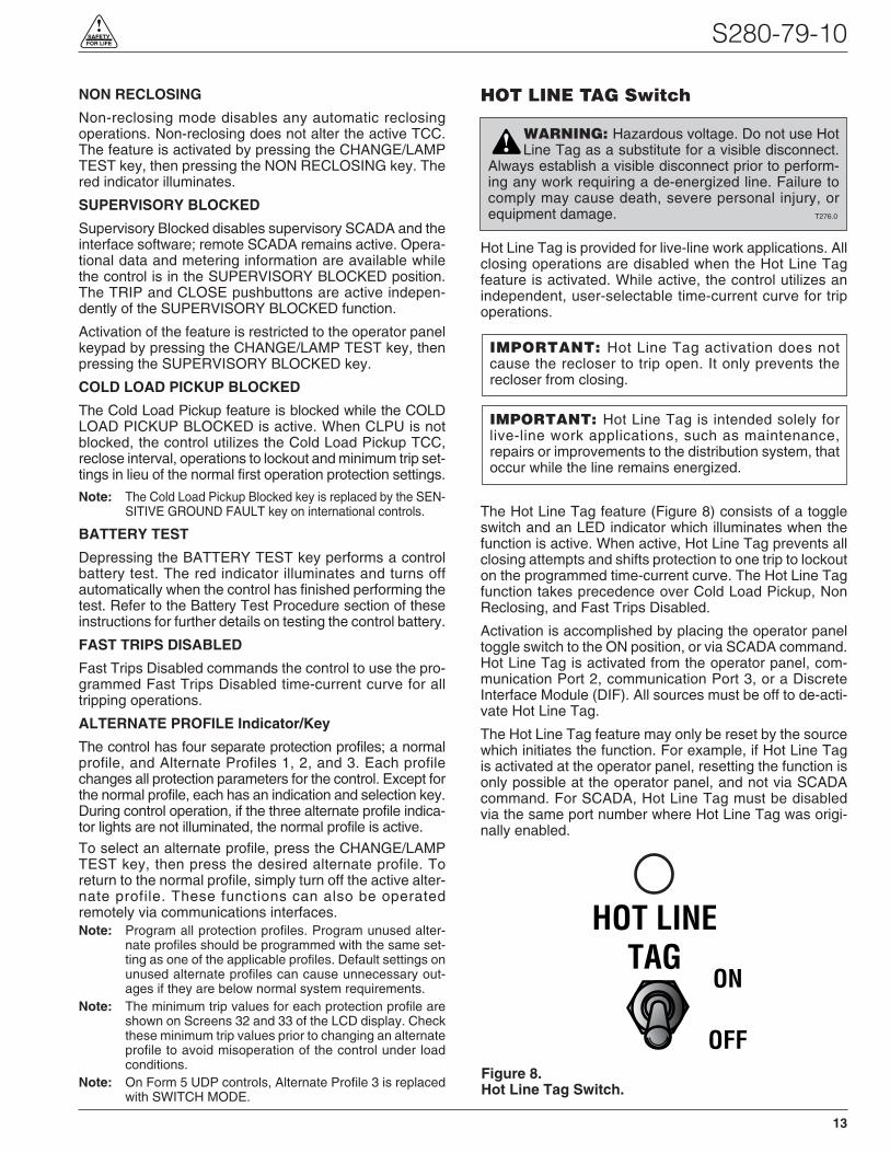
HOT LINE TAG Switch
Hot Line Tag is provided for live-line work applications. Allclosing operations are disabled when the Hot Line Tagfeature is activated. While active, the control utilizes anindependent, user-selectable time-current curve for tripoperations.
The Hot Line Tag feature (Figure 8) consists of a toggleswitch and an LED indicator which illuminates when thefunction is active. When active, Hot Line Tag prevents allclosing attempts and shifts protection to one trip to lockouton the programmed time-current curve. The Hot Line Tagfunction takes precedence over Cold Load Pickup, NonReclosing, and Fast Trips Disabled.
Activation is accomplished by placing the operator paneltoggle switch to the ON position, or via SCADA command.Hot Line Tag is activated from the operator panel, com-munication Port 2, communication Port 3, or a DiscreteInterface Module (DIF). All sources must be off to de-acti-vate Hot Line Tag.
The Hot Line Tag feature may only be reset by the sourcewhich initiates the function. For example, if Hot Line Tagis activated at the operator panel, resetting the function isonly possible at the operator panel, and not via SCADAcommand. For SCADA, Hot Line Tag must be disabledvia the same port number where Hot Line Tag was origi-nally enabled.
S280-79-10
13
!SAFETYFOR LIFE
HOT LINETAG
ON
OFFFigure 8.Hot Line Tag Switch.
WARNING: Hazardous voltage. Do not use HotLine Tag as a substitute for a visible disconnect.
Always establish a visible disconnect prior to perform-ing any work requiring a de-energized line. Failure tocomply may cause death, severe personal injury, orequipment damage. T276.0
!
IMPORTANT: Hot Line Tag is intended solely forlive-line work applications, such as maintenance,repairs or improvements to the distribution system, thatoccur while the line remains energized.
IMPORTANT: Hot Line Tag activation does notcause the recloser to trip open. It only prevents therecloser from closing.

RS-232 Communication PortThe standard Form 5 control is equipped with a operatorpanel RS-232 port for interface with a personal computerrunning the Form 5 interface software program. This nine-pin female data communication equipment (DCE) Port 1permits the uploading of all programming informationstored in the control, including protection profiles, eventrecorder, data profiles, alarms, counters, and meteringinformation. Port 1 provides a simple means to downloadoperating parameters from a personal computer to thecontrol.The protocol, baud rate and address for Port 1 areidentified from the LCD display.
If a fiber-optic or RS-232 accessory board is connected toPort 2 (located on the back of the operator panel) anyexternal electrical connection from the operator panel willdisable the accessory board.
Note: The operator panel RS-232 port is intended only fortemporary connection of a personal computer. Perma-nent serial communications must be made via the RS-232 or fiber-optic accessory board.
Battery Test ProcedureThe condition of the control battery is tested by depress-ing the BATTERY TEST hot key on the operator panel. Noexternal current/voltage meter is necessary for testing.
The control performs a self-test every 12 hours or wheninitiated by an external command. When a battery test isinitiated, the spurious charge is first drained to allow thebattery voltage to equalize. A 10-ohm, 55-watt resistor isthen placed across the battery terminals and a voltagedrop is calculated. If the drop from the equalized voltageto the test voltage exceeds 2 volts, then the CHECK BAT-TERY LED is illuminated.
To perform a battery test:
1. Using the Next and BACK keys, scroll through theLCD display to Screen 31, the Battery Monitor screen.
2. Record the NORMAL VOLTS and NORMAL CUR-RENT readings from the screen.
Note: Voltage should be between 25 to 31 volts withhigher readings at colder temperatures. Under nor-mal conditions with ac connected and the batterytrickle charging, the current should read less than20 mA. With ac connected and in bulk chargingmode, current will range from 12 to 600 mA. With acdisconnected and the battery supplying the load,current will read -180 mA to -600mA depending onaccessories connected.
3. Momentarily, press the CHANGE/LAMP TEST key,then BATTERY TEST key.
Note: AC power can be either connected or disconnectedfor Step 3.
4. Record the TEST VOLTS reading from the LCD andthe status of the CHECK BATTERY LED. Service thebattery if the CHECK BATTERY LED is illuminated.
Control FeaturesThe Form 5 recloser control offers numerous standardfeatures and accessories that allow the user the utmostflexibility in designing a control suitable for their applica-tion requirements.
Under/Over Frequency LoadsheddingThe Form 5 control includes provisions for frequencyloadshedding that trips the recloser for conditions of underor over system frequency. Access to this feature isthrough frequency threshold, trip time, and allowable volt-age threshold.
With the auto-restoration feature, the Form 5 can be set toclose the recloser after the system frequency and voltagehave recovered. Parameters available for setting includefrequency and voltage thresholds and time delay.
A frequency alarm is available and can be configured fornotification.
Voltage Protection (120 Vac-based)Voltage protection functionality is included as standard onall Form 5 controls. A recloser trip will be issued for underand over voltage conditions when the monitored voltagefalls outside user-specified limits for a selectable time.Response mode includes any single-phase, all threephases, and single-phase with three-phase inhibit.Response mode facilitates protecting against a singlephase condition common when a high side fuse operateson a distribution transformer. Parameters are also avail-able to provide auto restoration after a trip. A voltagealarm is available and can be configured for notification.
Protection ProfilesFour separate protection profiles are included to allow theuser to adapt overcurrent settings for varying system con-ditions such as load, live line work or weather. The activeprofile is selected from the operator panel or with the inter-face software or SCADA (Figure 9). Each profile has 14TCC specifications plus reclose intervals, sequence coor-dination and reset times to maintain independent protec-tion parameters.
Kyle Form 5, Form 5 UDP, Form 5 DC NOVA Recloser Control Installation and Operation Instructions
14
Figure 9.Interface software sample protection profile.

Power MeteringPower metering includes single- and three-phase Watts,VARS, KVARS, KWH measurements, and the per phaseand total system Power Factor (PF).
Power Factor Sign MeteringThis feature allows a user to configure the sign that isapplied to the power factor. The user may select betweenthe standard definition of power factor (cosine of anglebetween current and voltage) or the Cooper Power Sys-tems default of the power factor sign following power flow.
Voltage MeteringSix voltages (3-source and 3-load) are metered as stan-dard on the Form 5 control. The user selects either phase-to-phase or phase-to-ground values from the controloperator panel, interface software, or serial communica-tions. This reference is changed by selecting the voltagesensor correction in the “Hardware” setup portion of theinterface software.
Fast Trips DisabledFast Trips Disabled provides the user a quick and effi-cient method for reducing momentary interruptions or“blinks”. When activated from the front keypad, pro-grammed trips to lockout will time according to theselected time-current curve for Fast Trips Disabled. Thiscurve is programmable for both phase and ground oneach protection profile. A separate trips-to-lockout settingis also provided. See Figure 9.
Trip Failure DetectionThe Trip Failure Detection feature is an internal diagnos-tic alarm for verifying the proper operation of circuit trip-ping and fault clearing of the recloser. Trip Failuredetection indicates the recloser has failed to trip allphases following a trip signal from the control. Failure totrip is assumed if a current of at least 10 Amps is detectedapproximately 2 seconds after the trip signal is initiated.
Upon activation of the feature, these four LEDs flash 1second on, 1 second off (Figure 10):
• RECLOSER MALFUNCTION
• RECLOSER CLOSED
• RECLOSER OPEN
• CONTROL LOCKOUT
The Trip Failure Detection alarm may be triggered frommany potential sources including mechanical, electrical,control, or interrupter failure. Interrupter failure mayinclude loss of vacuum in a vacuum interrupter.
To clear Trip Failure Alarm, depress and hold the RESETTARGETS/RESET MAX CURRENTS keypad for 3 sec-onds. This also resets targets and demand currents.
Note: There is no remote reset available with the trip failuredetection feature. It cannot be remotely turned off.
When the trip failure alarm is activated, an event isrecorded and a status alarm activated (if enabled) andpreserved during system resets.
To test the Trip Failure Detection feature, see TestingWith Type MET Tester in the TESTING AND TROU-BLESHOOTING section of this manual.
S280-79-10
15
!SAFETYFOR LIFE
AC POWER
ABOVE MIN TRIP
REVERSE POWER FLOW
RECLOSER MALFUNCTION
CHECK BATTERY
BUSHINGS 1-2 FAULT TARGET
BUSHINGS 3-4 FAULT TARGET
BUSHINGS 5-6 FAULT TARGET
GROUND FAULT TARGET
SENSITIVE-GROUND FAULT TARGET
BUSHINGS 1-2 VOLTAGE
BUSHINGS 3-4 VOLTAGE
BUSHINGS 5-6 VOLTAGE
RECLOSER CLOSED
RECLOSER OPEN
CONTROL LOCKOUT
Figure 10.RECLOSER MALFUNCTION, RECLOSER CLOSED,RECLOSER OPEN and CONTROL LOCKOUT LEDswill blink for the affected phase as indication of TripFailure.
DANGER: Explosion. Stay clear of a recloserthat is in a trip failure mode. A recloser in trip fail-
ure mode may explode resulting in death or severe per-sonal injury. T271.0
!
IMPORTANT: The recloser must be isolated and de-energized immediately upon detection of trip failure.Follow proper procedures and safety practices to iso-late and de-energize the recloser.
WARNING: Hazardous voltage. This device isnot a substitute for a visible disconnect. Follow all
locally approved safety practices. Failure to followproper safety practices can result in contact with highvoltage, which will cause death or severe personalinjury. G112.1
!

Manual Close DelayManual Close Delay provides a delay from the time thatthe manual CLOSE button is pushed to the time the man-ual close operation is performed.
The delay is programmable from 0 to 60 seconds in 1 sec-ond increments. A programmed delay value can be over-ridden for immediate closing by pressing the CLOSEbutton a second time.
An active Manual Close Delay can be canceled by press-ing the TRIP/LOCKOUT button.
The default setting has the feature disabled (0 seconds).The RECLOSER CLOSED LED indicates the status of thefeature. See Figure 11.
Harmonic AnalysisExtensive harmonic analysis is performed by the Form 5control for both currents and voltages. Analysis is per-formed on-line (updates every 30 seconds) or demandintegrated to user-specified time values. The Total Har-monic Distortion (THD) for current and voltage is availablefrom the operator panel display (Figure 12) while com-plete analysis, including graphing capabilities, is providedfrom the Form 5 interface software.
Reverse Power FlowFeeder load monitoring is enhanced with the inclusion ofthe power flow monitoring feature. When power flow fromthe load to the source side of the recloser is detected, thecontrol illuminates an operator-panel indicator. Responsetime to a reverse power condition is one second. An alarmis also available for remote interrogation.
Note: Voltage sensor polarity must be correct for reversepower flow to function properly.
Event RecorderThe Event Recorder maintains a log of operating eventsfor later readout and analysis by the user. Approximately500 events can be stored in non-volatile memory. Foreach event type, time of occurrence, and other relevantinformation is stored. When the event recorder hasreached is capacity, the oldest event is deleted as a newevent is added.
HistogramsDemand metered voltages and currents can be reportedusing the histogram tool. It displays the number of occur-rences of a variable versus its value in between user-defined minimum and maximum limits. Date and time arerecorded for the maximum and minimum demand values.
Data ProfilerA fully configurable data profiler is available which allowsthe user to collect information by sampling demand dataat selectable intervals. These time-stamped values canthen be plotted to determine weekly load profiles, dailyharmonic disturbances or hourly voltage fluctuations. Thedata profiler can provide more than 200 days of informa-tion, depending upon configuration parameters.
Cold Load PickupCold Load Pickup (CLPU) must be enabled through theinterface software (Figure 13) before it can be activatedremotely or from the CLOSE pushbutton on the operatorpanel. The CLPU feature provides the user with the abil-ity to alter protection for abnormal system conditions. It isactive for a programmable time interval which begins witheach manual close. Once this time elapses, protectionreverts back to the programmed sequence. Use the Form5 control interface software to program the activation timeand time-current characteristics applicable to Cold-LoadPickup.
Note: When CLPU is active, the control utilizes the Cold LoadPickup TCC, reclose interval, operations to lockout, andminimum trip settings in lieu of the normal protectionsettings.
Kyle Form 5, Form 5 UDP, Form 5 DC NOVA Recloser Control Installation and Operation Instructions
16
Figure 13.Interface software Cold Load Pickup settings.
Figure 12.Form 5 operator panel harmonic readout.
NEXT BACK
RESETTARGETS CHANGE
Pg14 Gnd %THDIPh1-2 %THDIPh3-4 %THDIPh5-6 %THDI
RESETMAX CURRENT
LAMPTEST
RECLOSER CLOSED
RECLOSER OPEN
CONTROL LOCKOUT
Figure 11.The blinking of the RECLOSER CLOSED LED indi-cates Manual Close Delay is active.
AlarmsStatus and data alarms are available for many controlparameters such as voltage, currents, thresholds. Dataalarm function compares metered data to user-pro-grammed alarm high and low limits and issues an alarm ofuser-specified priority if limits are exceeded. The statusalarm function monitors status and issues an alarm ofuser-defined priority when the user programmed alarmconditions are met. The alarms are reported via commu-nication ports and can be configured to trigger a data pro-file and event record. Alarms do not affect the protectionfunctions of the control.
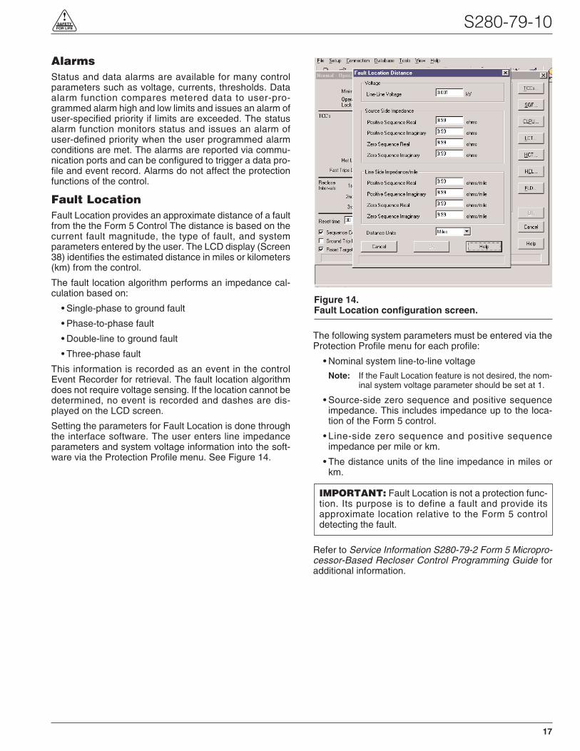
Fault LocationFault Location provides an approximate distance of a faultfrom the the Form 5 Control The distance is based on thecurrent fault magnitude, the type of fault, and systemparameters entered by the user. The LCD display (Screen38) identifies the estimated distance in miles or kilometers(km) from the control.
The fault location algorithm performs an impedance cal-culation based on:
• Single-phase to ground fault
• Phase-to-phase fault
• Double-line to ground fault
• Three-phase fault
This information is recorded as an event in the controlEvent Recorder for retrieval. The fault location algorithmdoes not require voltage sensing. If the location cannot bedetermined, no event is recorded and dashes are dis-played on the LCD screen.
Setting the parameters for Fault Location is done throughthe interface software. The user enters line impedanceparameters and system voltage information into the soft-ware via the Protection Profile menu. See Figure 14.
The following system parameters must be entered via theProtection Profile menu for each profile:
• Nominal system line-to-line voltage
Note: If the Fault Location feature is not desired, the nom-inal system voltage parameter should be set at 1.
• Source-side zero sequence and positive sequenceimpedance. This includes impedance up to the loca-tion of the Form 5 control.
• Line-side zero sequence and positive sequenceimpedance per mile or km.
• The distance units of the line impedance in miles orkm.
Refer to Service Information S280-79-2 Form 5 Micropro-cessor-Based Recloser Control Programming Guide foradditional information.
S280-79-10
17
!SAFETYFOR LIFE
IMPORTANT: Fault Location is not a protection func-tion. Its purpose is to define a fault and provide itsapproximate location relative to the Form 5 controldetecting the fault.
Figure 14.Fault Location configuration screen.

Directional Sensitive Ground/Earth(SGF/SEF) FaultThe Directional SGF/SEF Fault feature adds directionalcapabilities to the SGF/SEF protection features. It pro-vides a sensitive ground/earth trip if the fault is downlineof the recloser on a radial distribution system. DirectionalSGF/SEF is used on ungrounded Delta systems for sup-pression of ground trips for faults occurring on other circuitbranches.
The user sets the parameters for Direction SGF/SEFthrough the interface software via the Protection Profilemenu. See Figure 15. In addition to the normal (non-direc-tional) SGF/SEF settings, the user enters the followingdirectional SGF/SEF parameters:
• Direction Enable
Note: If Direction Enable is not selected, SGF/SEF trippingoccurs through normal (non-directional) settings.
• Maximum Torque Angle (-180° to 180°, in 1° increments)
• Torque Angle Width (10° to 90°, in 1° increments)
• Zero Sequence Voltage (V0) Threshold (4 to 130 V)
The Maximum Torque Angle parameter determines theangle of maximum tripping sensitivity between the phaseangle of the zero sequence voltage and current at the timeof fault. The setting of this value depends on knowledgeof the power system. Typically, a resistive fault has avalue of 0°, and a capacitive fault has a value of 90°.
Torque Angle Width parameter restricts the tripping to anangle of plus or minus the specified width about theTorque angle setting. For example, if the MaximumTorque Angle is 45°, and the Torque Angle Width is set for10°, then the control will trip at angles between 35° and55°.
The Zero Sequence Voltage Threshold is used to set thethreshold voltage below the disabled directional SGF/SEFtripping voltage.
Note: In most cases, a default value of 4 is adequate.
Directional SGF/SEF Fault is recorded as an event in thecontrol Event Recorder for retrieval. Refer to Service Infor-mation S280-79-2 Form 5 Microprocessor-Based RecloserControl Programming Guide for additional information.
Kyle Form 5, Form 5 UDP, Form 5 DC NOVA Recloser Control Installation and Operation Instructions
18
Figure 15.Directional SGF/SEF configuration screen.

CommunicationsCommunication PortsThe Form 5 control has three communication ports fromthe CPU module. Two of the three ports are user-acces-sible. Communication Port 1 is the operator panel LCDdisplay where data is exchanged between the CPU andthe operator panel. Though not user-configurable, Port 1allows for flexible modifications to the front panel for cus-tom applications.
The operator panel RS-232 communication Port 2 pro-vides temporary local personal computer (PC) accesswhen connected with a standard 9-pin cable. Port 2 pro-vides a dual communication interface for the user. Theport includes a software switch for two external connec-tions; the operator panel RS-232 DB-9 connector, or thefiber-optic/RS-232 communication accessories. Localconnection to the operator panel RS-232 connectiontakes precedence over the communication accessory.Disconnecting the operator panel RS-232 communicationautomatically reconnects the communication accessoryto Port 2.
Accessory Ports 2 and 3 are resident on the back of theoperator panel and can be configured to either 2179 orDNP3.0 protocols. Port 3 provides uninterrupted commu-nication to the RS-232 or Fiber-Optic accessory, and isnot affected by any other port or physical connection.
Figure 16 illustrates the communication configuration forserial ports1, 2, and 3.
Fiber-Optic/RS-232 AccessoryTwo sets of receive and transmit LEDs (Figure 17) areprovided on the operator panel for fiber-optic and RS-232communications. The TX2 and RX2 LEDs illuminate whencommunicating with the operator panel RS-232 port. TheTX3 and RX3 LEDs illuminate when communicating witheither the fiber-optic or RS-232 interface accessoryboards on communication Port 3.
The RS-232 accessory board and the fiber-optic acces-sory boards are located behind the operator panel. Eachaccessory board can be connected to either Port 2 or Port3; no two boards can use the same port. The operatorpanel LEDs indicate the status of communication on theaccessory boards. Temporary connections to the operatorpanel RS-232 port disables fiber-optic or RS-232 commu-nication at Port 2.
Port 3 provides uninterrupted communication to aremote terminal unit (RTU). Refer to S280-79-4 Form 5Serial communications Accessory Operation Instruc-tions for additional information.
ProtocolsThree protocols are available for the Form 5 control andare factory-configurable to communication Ports 2 and 3.
The protocols are:
• Cooper Power Systems 2179
• DNP3.0, Level 3
• S-Comm Protocol accessory
Protocol DNP3.0 includes “Unsolicited Report by Excep-tion” functionality and Protocol 2179 includes 2-bit statusfunctionality.
Complete documentation for Cooper Power Systems pro-tocols are:
• Reference Data R280-90-12, Serial CommunicationProtocol 2179
• Reference Data R280-90-13, Communication PointDatabase for Protocol 2179
• Reference Date R280-90-14, Communication PointDatabase for Protocol DNP3.0
Control InformationControl information, including firmware version anddatabase version, is factory installed and can not bealtered by the user. This information is accessible fromthe LCD display, Screen 39.
Communication Ports 2 and 3 settings can be referencedfrom the LCD display, Screens 40 and 41 respectively.(Port 1 shares the same settings as Port 2.)
S280-79-10
19
!SAFETYFOR LIFE
COMMUNICATIONSPORT 1
(Internal Use Only)
COMMUNICATIONSPORT 2(Shared)
(Metering, HistogramsProfiles, Alarms, Targets)
CPU
TEMPORARYENGINEERING
(Local PC)
OPERATOR PANELDISPLAY AND
KEYPAD
OPERATIONS
OPERATORPANELRS-232
ENGINEERING(Radio, Fiber-Optic, Modem)
RS-232 orFIBER-OPTIC
ACCY
RS-232 orFIBER-OPTIC
ACCY
SCADA SYSYEM(Radio, Fiber-Optic, Modem)
COMMUNICATIONS PORT 3
(Dedicated)
AUTO TRANSFERSWITCH(Operator PanelConnection DisablesAccessory)
Figure 16.Control communication port configuration.
TX 2
RX 2
TX 3
RX 3 RS232
Figure 17.Fiber-Optic/RS-232 receive and transmit LEDs anddata port on the operator panel. The TX2 and RX2LEDs illuminate during communication with theoperator panel RS-232 port.

AUXILIARY POWER FORACCESSORIES
Connection P9 (Figure 18) on the Power Supply moduleprovides 24Vdc (12Vdc is available) to power radio com-munication units, RTUs and other accessories. The auxil-iary power provides 40W peak load capability. Auxiliarypower is fused and current-limited to prevent user loadsfrom disabling the control.
Customer 28V connections for auxiliary power are madeto terminals 3 and 1 and are continually energized. Ter-minal 2 and 4 are not used at this time.
RECLOSER INTERFACE (RIF)MODULE CONFIGURATION
The Recloser Interface (RIF) Module is factory-configuredat 120Vac. For operating voltages other than 120Vac, theRIF module must be removed from the control cabinet forconfiguration.
To remove the RIF Module for configuration:
1. Disconnect the control battery.
2. Remove the four connectors from the front of the RIFModule.
3. Remove the nut and disconnect the grounding strap tothe operator panel. See Figure 4.
4. Disconnect the wiring harness connectors from thebottom of the RIF Module.
Note: Press the locking tabs to release the harness con-nectors.
5. Remove the four 11mm (.437 in) screws securing theboard to the mounting bracket.
6. Pull the module out of the cabinet.
The dip switches are located on the side of the module.
7. Configure the RIF board as shown in Figure 19.
8. After configuration, place the module back into posi-tion in the control cabinet and secure to the mountingbracket with screws previously removed.
9. Replace nut securing the RIF Module grounding strap
10. Replace all connectors on the front and bottom of theRIF Module.
Kyle Form 5, Form 5 UDP, Form 5 DC NOVA Recloser Control Installation and Operation Instructions
20
CAUTION: Equipment damage. Always wear a ground-ing wrist strap to control static electricity before handlingcircuit boards. Failure to use this strap may result in cir-cuit board damage. T253.1
INPUT VOLTAGESELECTION
INPUT VOLTAGESELECTION
POLE 2POLE 1POLE 2
POLE 1
S7
S8
POLE 1
POLE 2
POLE 2POLE 1POLE 2
POLE 1
POLE 1
POLE 2
S7
BUSHING 2 (XØ)
BUSHING 4 (YØ)
BUSHING 6 (ZØ)
BUSHING 1 (AØ)
BUSHING 3 (BØ)
BUSHING 5 (CØ)
OFF ON
OFF ON
SENSORVOLTAGE POLE1 POLE2
12Vac OFF OFF120Vac* OFF ON240Vac ON ON
Example shown for 120Vac operation:
*120Vac is factory-set configuration
Figure 19.Recloser Interface (RIF) Module indicates the fac-tory-configured metering voltage (120Vac).
POWER
SUPPLY
P9
AUX
F1GDC-1A
P8
CPU
SW (-) 428V (-) 3
SW (+) 228V (+) 1
Figure 18.Power Supply Module Connection P9 provides24Vdc power to radio communication units.
IMPORTANT: The Form 5 control must be com-pletely de-energized prior to removing and configuringthe RIF board.

The UDP function allows the Form 5 control to become aswitch control to provide indication of overcurrent trip con-ditions without issuing an overcurrent trip signal. The con-trol is in the recloser mode when the feature is in the OFFposition, and in the switch mode when the feature isACTIVE.
While in the switch mode, all automatic open and closeoperations of the recloser (including overcurrent voltageand frequency) are blocked. Fault targeting, metering,alarms, and event recording functions are active.
This non-tripping fault indication state is initiated via aoperator panel pushbutton (labeled SWITCH MODE), dig-ital SCADA, or discrete SCADA. The UDP feature haslocal indication at the operator panel (LED), digital indica-tion, and remote indication via status contacts on the Dis-crete Interface (DIF) module 1.
S280-79-10
21
!SAFETYFOR LIFE
Figure 21.Interface software Switch Mode settings.
GND TRIPBLOCKED
NONRECLOSING
SUPERVISORYBLOCKED
COLD LOADPICKUP
BLOCKED
BATTERYTEST
FASTTRIPS
DISABLED
ALTERNATEPROFILE
NO. 1
ALTERNATEPROFILE
NO. 2
SWITCHMODE
Figure 20.Function/Indication pushbuttons for the Form 5equipped with the UDP accessory.
FORM 5 UNIVERSAL DEVICE PROTECTION (UDP) CONTROL
CONTROL OK
AC POWER
ABOVE MIN TRIP
REVERSE POWER FLOW
RECLOSER MALFUNCTION
CHECK BATTERY
BUSHINGS 1-2 FAULT TARGET
BUSHINGS 3-4 FAULT TARGET
BUSHINGS 5-6 FAULT TARGET
GROUND FAULT TARGET
SENSITIVE-GROUND FAULT TARGET
AØ
BØ
CØ
RECLOSER CLOSED
RECLOSER OPEN
CONTROL LOCKOUT
BACK NEXT
LAMPTEST
CHANGERESET
TARGETS
RESETMAX CURRENT
GND TRIPBLOCKED
NONRECLOSING
SUPERVISORYBLOCKED
COLD LOADPICK UP
BLOCKED
BATTERYTEST
FASTTRIPS
DISABLED
ALTERNATEPROFILE
NO. 1
ALTERNATEPROFILE
NO. 2
SWITCHMODE
HOT LINETAG
ON
OFF
TX 3
RX 3
CLOSETRIP(LOCKOUT) KYLE®
FORM 5/UDPRECLOSER CONTROL
RS232
TX 2
RX 2
SOURCEVOLTAGE
XØ
YØ
ZØ
LOADVOLTAGE
Figure 22.Form 5/UDP Operator Panel.

The Kyle Form 5 recloser control can be equipped with adc-to-dc converter, interface circuit, and a fully shielded19-pin cable for use with a Type DC NOVA recloser. SeeFigure 23.
The dc-to-dc converter board (Figure 24) converts the con-trol’s 24 Vdc battery supply voltage to 53 Vdc to drive thetrip/close capacitors in the NOVA mechanism. The outputof the board is separately fused for operator indication.
The dc-to-dc converter houses voltage monitoring andconditioning circuits which protect the battery from failureand provides trip/close operations without AC power. The19-pin control cable interfaces the NOVA dc recloser tothe Form 5 control through the interface circuit. The cablealso provides AC power from the control to the reclosermechanism heater.
Kyle Form 5, Form 5 UDP, Form 5 DC NOVA Recloser Control Installation and Operation Instructions
22
FORM 5 DC NOVA CONTROL
Form 5Control
PotentialTransformer (120/240Vac)
120Vac/240VacPower Cable
19 Pin Control Cable
OP
EN
dc NOVA
Figure 23.Connections of a Form 5 control with dc NOVAaccessory to a dc NOVA recloser.
Figure 24. 99007KM
Dc-to-dc converter located behind Form 5 operatorpanel (removed).

S280-79-10
23
!SAFETYFOR LIFE
DISCRETE INTERFACE (DIF)ACCESSORY
The Discrete Interface (DIF) module accessory (Figure25) permits connection of contact-type input devices(switches, relays) and discrete indicating devices (relays,LEDs, lamps) to the Form 5 control to effect local discreteinput/output (I/O). The DIF module accessory is used forsupplementing normal local controls and status indicatorsfor discrete SCADA functions. All DIF inputs and outputshave been factory-set and are shown in Figure 27.
The DIF module contains 12 factory-set inputs and out-puts for discrete SCADA functions. Each Form 5 controlcan accommodate two DIF modules.
Whetting voltage for the DIF inputs can be supplied by theDIF module or by the customer as shown in Figure 26.
Note: 28 Vdc (nominal) is provided from the DIF module viaconnector P5 for use as whetting voltage for inputs toP4. As an alternative, the user can supply whetting volt-age from an auxiliary source, such as a RTU.
The input voltage range is 12 to 120 Vac or Vdc. The 12outputs are Form C relay contacts. Six of the module out-puts are latching and the other six are non-latching.
Note: Latching is defined as an output that retains its statuswhen control power is removed.
Non-latching is defined as an output that changes itsstatus when control power is removed.
Note: A remote function is not controlled by the SUPERVI-SORY BLOCKED switch.
Customer ConnectionInformation
Figure 25 shows the customer-supplied wiring of whettingvoltage for DIF module inputs. Connection is made fromterminal P5 on the DIF module to the respective connec-tions on P4 inputs 1 through 12.
Figure 27 shows customer connections to the DIF outputsat P2 and P3.
4
3
2
1
4321
8765
1211109
6
5
4
3
2
1
4321
8765
1211109
12
11
10
9
8
7
4321
8765
1211109
INPUT COMMON
28V (–)28V (+)
OUTPUT COMMON
P5
P3
P2
P4
DISCRETEINTERFACE
MODULEACCESSORY
WHETTINGVOLTAGE
UNLATCHEDOUTPUTS
LATCHEDOUTPUTS
INPUTS(12 TO 120VAC OR VDC)WHETTINGVOLTAGE
4321
8765
1211109
Figure 25.Discrete Interface (DIF) Module.
4
3
2
1
INPUT COMMON
28V (-)28V (+)
OUTPUT COMMON
To P4Inputs 1 thru 12
P5
Customer-SuppliedWiring for Whetting Voltage
REMOTECONTACTSNote: Wiring to P5-2 and P5-3 can be
reversed if necessary.
Figure 26.Customer connections for supplying whetting volt-age to DIF inputs.
CAUTION: Equipment damage; misoperation.External leads must be shielded and the shield
must be grounded at both ends. Terminate each leadwith a 320 Vac, 160 Joules metal oxide varistor (MOV),or equivalent, at the remote end. Attach MOVs betweenthe leads and ground. Failure to properly shield andprotect leads can result in equipment damage and/orunintentional operation. G117.3
!
CAUTION: Equipment damage. Do not drill con-nection holes into the top of the cabinet. Connec-
tion holes in the top of the cabinet will allow moisture toseep into the control and damage the components orcause control misoperation. Failure to comply will voidthe control’s factory warranty. T249.0
!
IMPORTANT: Do not use DIF module for overcurrentprotection. Digital SCADA can be used for this applica-tion. The control gives priority to TCC timing and issu-ing a trip signal rather than changing the status of a DIFoutput or responding to a DIF input.

Kyle Form 5, Form 5 UDP, Form 5 DC NOVA Recloser Control Installation and Operation Instructions
24
R
R
FORM 5 CONTROL
Remote Terminal Unit (RTU)
NORMAL PROFILE
NON-RECLOSING
COLD LOAD PICKUP BLOCKED
INPUT COMMON
SUPV. CLOSE
SUPV. TRIP & L.O.
Not All RemoteConnections
Shown
INPUTVOLTAGE
COMMON
67
85
12
43
910
1112
Discrete InterfaceModule (DIF)
REMOTE HOT LINE TAG
SUPERVISORY GROUND TRIP BLOCKED
SUPERVISORY ALTERNATE PROFILE 1
SUPERVISORY ALTERNATE PROFILE 2
SUPERVISORY ALTERNATE PROFILE 3*(*SWITCH MODE ON FORM 5 UDP)
SUPERVISORY NORMAL PROFILE
SUPERVISORY NON-RECLOSING
SUPERVISORY COLD LOAD PICKUP BLOCKED
REMOTE TRIP AND RECLOSE
REMOTE TRIP AND LOCKOUT
SUPERVISORY BLOCKED
AC POWER
CONTROL OK
RECLOSER OPEN
HOT LINE TAG
GROUND TRIP BLOCKED
ALTERNATE PROFILE 1
ALTERNATE PROFILE 2
ALTERNATE PROFILE 3
P5
P3
P4
P2
G
*28V (–)
*28V (+)
OUTPUT COMMON
67
85
12
43
910
1112
67
85
12
43
910
1112
*28 Vdc (nominal)supplied by
DIF module forwhetting voltage.
Figure 27.Customer connections to DIF module outputs with shielding and surge protection.

S280-79-10
25
!SAFETYFOR LIFE
Standard and UDP ControlsStandard and UDP Form 5 control DIF inputs and outputsare described in the following pages.
Maximum Switching Voltage: . . . . . 135 Vac 110 Vdc
Maximum Switching Loading: . . . . . 600 mA
Maximum Pickup-Release Time: . . 3 msec (does not count control response time)
Input Protection: . . . . . . . . . . . . . . . Shunting type using MOVs and capacitors
Minimum Detection Level: . . . . . . . . . . . . . . . . . . . . . . . . 8 Vac (50 or 60Hz) 10 Vdc
Maximum Operating Voltage: . . . . . . . . . . . . . . . . . . . . . 135 Vac (50 or 60Hz) 175 Vdc
Input Impedance: . . . . . . . . . . . . . . . . . . . . . . . . . . . . . . . 10 k minimum (inputs are current limited)
Maximum Input Loading: . . . . . . . . . . . . . . . . . . . . . . . . . 2 mA per input
Maximum Leakage Rejection: . . . . . . . . . . . . . . . . . . . . . 1 mA
Maximum Pickup Time: . . . . . . . . . . . . . . . . . . . . . . . . . . 10 msec (does not count control response time)
Minimum Input Pulse Time: . . . . . . . . . . . . . . . . . . . . . . . 100 msec
Minimum Transition Time between Pulse Inputs: . . . . . . 200 msec
Input Protection: . . . . . . . . . . . . . . . . . . . . . . . . . . . . . . . Shunting type using MOVs and capacitors.Opto Isolation from input to system.
Voltage Level: . . . . . 28 Vdc (nominal)
Output Current: . . . . 30 mA maximum
TABLE 1DIF Input Ratings
TABLE 2Whetting Voltage Source(Supplied by Internal Voltage Source of DIF Module)
TABLE 3DIF Output Ratings
IMPORTANT: Each DIF contains a small, isolatedcurrent source for use with external dry contacts. Thissupply is intended for use with the DIF inputs only andmust not be used for powering external circuits. This isconsidered a dry contact input for customer connection.

Kyle Form 5, Form 5 UDP, Form 5 DC NOVA Recloser Control Installation and Operation Instructions
26
Note: Supervisory Alternate Profile 3 replaced by SwitchMode on UDP controls.
Standard and UDP Control DIF Module 1Inputs
The DIF inputs are factory-configured as momentary (0.25 sec. duration) or maintained functions. Supervisory signalsdo not have any effect when supervisory blocked is active. Remote inputs function when supervisory is blocked.
Input Connector Function Description
1 P4-1 Supervisory Trip and Lockout Supervisory Trip and Lockout trips the recloser open and locks outthe control. The control remains locked out until closed manually orby the supervisory close feature. A momentary signal is required.
2 P4-2 Supervisory Close Supervisory Close initiates a closing signal to the recloser. Amomentary signal is required for proper operation.
3 P4-3 Remote Hot Line Tag Remote Hot Line Tag performs the same functions as the HOTLINE TAG switch on the operator panel. Remote Hot line Tag isactivated by a maintained SCADA command, a serial command,or locally via a operator panel switch. This input is active regardlessof the state of the supervisory function.
4 P4-4 Supervisory Ground Trip Block Supervisory Ground Trip Block provides supervisory operation ofground trip block by a remote momentary signal.
This input performs the same function as the GND TRIP BLOCKEDkey on the operator panel. This input is inactive if the Supervisoryfunction is disabled.
5 P4-5 Supervisory Alternate Profile 16 P4-6 Supervisory Alternate Profile 27 P4-7 Supervisory Alternate Profile 3*
8 P4-8 Supervisory Normal Profile Supervisory Normal Profile requires a momentary signal for properoperation.
This input is active with a whetting voltage and causes the controlto select Normal Protection Profile. This input is inactive if theSupervisory function is disabled.
Supervisory Alternate Profiles provides selection of alternate pro-grammed values for phase and ground. This feature is activated bya remote momentary signal.
These inputs are active with a momentary whetting voltage andcause the control to select the respective Supervisory Alternate Pro-file. The inputs are inactive if the Supervisory function is disabled.

S280-79-10
27
!SAFETYFOR LIFE
Standard and UDP Control DIF Module 1Inputs (cont’d)
Input Connector Function Description
9 P4-9 Supervisory Non-Reclosing Supervisory Non-Reclosing provides supervisory non-reclosinginput by a remote momentary signal.
This input performs the same function as the NON-RECLOSINGkey on the operator panel. This input is inactive if the Supervisoryfunction is disabled.
10 P4-10 Suprv Cold-Load Pickup Blocked This input performs the same function as the COLD LOADPICKUP BLOCKED key on the operator panel. This input is inac-tive if the Supervisory function is disabled. A momentary signal isrequired for proper operation.
11 P4-11 Remote Trip and Reclose Remote Trip and Reclose initiates a trip operation followed by areclose operation. A momentary signal is required for properoperation.
This input is active with a whetting voltage and causes the controlto perform a trip operation followed by a reclose operation. Thisinput is active regardless of the state of the Supervisory function.
12 P4-12 Remote Trip and Lockout Remote Trip and Lockout trips the recloser open and locks out thecontrol. It can be used for tripping from external relays and alarms.
A momentary signal is required for proper operation.
This input performs the same function as the TRIP (LOCKOUT)switch on the operator panel and is active regardless of the stateof the Supervisory function.

*Note: Supervisory Alternate Profile 3 replaced by SwitchMode on UDP controls.
Kyle Form 5, Form 5 UDP, Form 5 DC NOVA Recloser Control Installation and Operation Instructions
28
Standard and UDP Control DIF Module 1Outputs
The 12 outputs of the DIF Module are Form C relay contacts. Six of the outputs are latching and six are non-latching.
Note: Contacts shown in inactive mode.
Output Connector Function Type Description
1 P3-1 NC Normal Profile Non-LatchedP3-2 NO
2 P3-3 NC Non-Reclosing Non-LatchedP3-4 NO
3 P3-5 NC Cold-Load Pickup Blocked Non-LatchedP3-6 NO
4 P3-7 NC Supervisory Blocked Non-LatchedP3-8 NO
5 P3-9 NC AC power Non-LatchedP3-10 NO
6 P3-11 NC Control OK Non-LatchedP3-12 NO
7 P2-1 NO Recloser Open LatchedP2-2 NC
8 P2-3 NO Hot Line Tag LatchedP2-4 NC
9 P2-5 NO Ground Trip Blocked LatchedP2-6 NC
10 P2-7 NO Alternate Profile 1 LatchedP2-8 NC
11 P2-9 NO Alternate Profile 2 LatchedP2-10 NC
12 P2-11 NO Alternate Profile 3* LatchedP2-12 NC
Normal Profile is active only when Alternate Profiles areinactive. Normal reclosing operations will follow.
This output is active when the NON-RECLOSING indicatorin the operator panel is illuminated.
This output is active when the COLD LOAD PICKUPBLOCKED indicator on the operator panel is illuminated.
Supervisory Blocked prevents operation from supervisorycontrol. Programming is accessible from the operator panel.This output is active when the SUPERVISORY BLOCKEDindicator on the operator panel is illuminated.
AC power indicator is active when the control detects thepresence of AC power. This output is active when the ACpower indicator on the operator panel is illuminated.
Control OK indicator is active when the control is able to per-form protection operations. This output is active when theCONTROL OK indicator on the operator panel is illuminated.
Recloser Open indicator is active when the recloser signalsthe control that the recloser contacts are open. This output isactive when the RECLOSER OPEN indicator is illuminated.
These outputs are active when the respective ALTERNATEPROFILE indicators on the operator panel is illuminated.
With Hot Line Tag active, close circuit is disabled and theHOT LINE TAG indicator is illuminated. With Hot Line Taginactive, the control switched back to the previous time cur-rent curve for the active profile, close circuit is enabled andthe HOT LINE TAG indicator is off. This output is activewhen the operator panel indicator is illuminated.
Ground Trip Blocked causes the control to block ground trip-ping operations. This output is active when the GND TRIPBLOCKED INDICATOR on the operator panel is illuminated.

S280-79-10
29
!SAFETYFOR LIFE
Standard and UDP Control DIF Module 2Inputs
The DIF inputs are factory-configured as momentary or maintained functions. Whetting voltage for the DIF inputs issupplied by the DIF module or by the user. The input voltage range is 12 to 120 VAC or VDC.
Input Connector Function Description
1 P4-1 Supervisory Fast Trips Disabled This input performs the same function as the FAST TRIPS DIS-ABLED key on the operator panel and is inactive if the Supervisoryfunction is disabled. This is a momentary function.
2 P4-2 Supervisory Reset Targets This input performs the same function as the RESETTARGETS/RESET MAX CURRENT key on the operator panel.This input is inactive if the Supervisory function is disabled. This isa momentary function.
3 P4-3 Supervisory Operation Counter OFF The operation counter is disabled when this input is active with amaintained whetting voltage. This input is inactive if the Supervi-sory function is disabled.
4 P4-4 Supervisory Battery Test This input performs the same function as the BATTERY TEST keyon the operator panel. This input is inactive if the Supervisory func-tion is disabled. This is a momentary function.
5 P4-5 Supervisory SGF Blocked This input is active with a momentary whetting voltage and causesthe control to block, or unblock sensitive ground fault operations.The input is inactive if the Supervisory function is disabled.
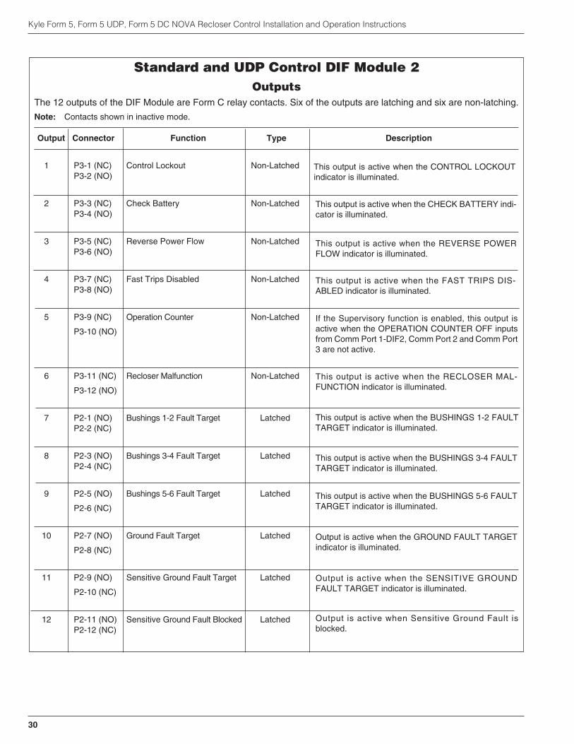
Kyle Form 5, Form 5 UDP, Form 5 DC NOVA Recloser Control Installation and Operation Instructions
30
Standard and UDP Control DIF Module 2Outputs
The 12 outputs of the DIF Module are Form C relay contacts. Six of the outputs are latching and six are non-latching.
Note: Contacts shown in inactive mode.
Output Connector Function Type Description
1 P3-1 (NC) Control Lockout Non-LatchedP3-2 (NO)
2 P3-3 (NC) Check Battery Non-LatchedP3-4 (NO)
3 P3-5 (NC) Reverse Power Flow Non-LatchedP3-6 (NO)
4 P3-7 (NC) Fast Trips Disabled Non-LatchedP3-8 (NO)
5 P3-9 (NC) Operation Counter Non-Latched
P3-10 (NO)
6 P3-11 (NC) Recloser Malfunction Non-Latched
P3-12 (NO)
7 P2-1 (NO) Bushings 1-2 Fault Target LatchedP2-2 (NC)
8 P2-3 (NO) Bushings 3-4 Fault Target LatchedP2-4 (NC)
9 P2-5 (NO) Bushings 5-6 Fault Target Latched
P2-6 (NC)
10 P2-7 (NO) Ground Fault Target Latched
P2-8 (NC)
11 P2-9 (NO) Sensitive Ground Fault Target Latched
P2-10 (NC)
12 P2-11 (NO) Sensitive Ground Fault Blocked LatchedP2-12 (NC)
This output is active when the CONTROL LOCKOUTindicator is illuminated.
This output is active when the CHECK BATTERY indi-cator is illuminated.
This output is active when the REVERSE POWERFLOW indicator is illuminated.
This output is active when the FAST TRIPS DIS-ABLED indicator is illuminated.
If the Supervisory function is enabled, this output isactive when the OPERATION COUNTER OFF inputsfrom Comm Port 1-DIF2, Comm Port 2 and Comm Port3 are not active.
This output is active when the RECLOSER MAL-FUNCTION indicator is illuminated.
This output is active when the BUSHINGS 1-2 FAULTTARGET indicator is illuminated.
This output is active when the BUSHINGS 3-4 FAULTTARGET indicator is illuminated.
This output is active when the BUSHINGS 5-6 FAULTTARGET indicator is illuminated.
Output is active when the GROUND FAULT TARGETindicator is illuminated.
Output is active when the SENSITIVE GROUNDFAULT TARGET indicator is illuminated.
Output is active when Sensitive Ground Fault isblocked.

Sensed CurrentsNote: Control only, does not include sensor tolerance, but
does include the phase current summing process.
Phase Current—Individual Phase Currents:
Range: 1 A to 10,000 A for 500:1 CTs
2 A to 20,000 A for 1000:1 CTs
4 A to 40,000 A for 2000:1 CTs
Accuracy:± 1 mA from 10 mA to 125 mA
0.8% from 125 mA to 1600 mA
(Control only, does not include sensortolerance.)
Ground Current—Vector Sum of Three-Phase Currents:
Range: 1 A to 5,000 A for 500:1 CTs
2 A to 10,000 A for 1000:1 CTs
4 A to 20,000 A for 2000:1 CTs
Accuracy: ± 3 mA from 10 mA to 125 mA
2.4% from 125 mA to 1600 mA
Sensed Source VoltagesThree-phase voltages used in voltage, power and power-factor related calculations:
Voltage measurement accuracy:
± 0.4V from 5V to 80V
0.5% from 80V to 135V
S280-79-10
31
!SAFETYFOR LIFE
INPUT ACCURACY

Initial ProgrammingPrior to Installation
The control must be programmed with all necessary oper-ating settings, all alternate profiles, and parameters priorto operation with an energized recloser.
Note: Program all protection profiles. Unused alternate pro-files should be programmed with the same settings asone of the applicable profiles. Default settings onunused alternate profiles can cause unnecessary out-ages if they are below normal system requirements.
Initial programming of the control is the responsibility of aqualified technician or engineer familiar with control func-tions and programming parameters required for the spe-cific recloser installation.
The control must be programmed with the Form 5 inter-face software.
Control / Recloser CompatibilityReclosers manufactured prior to June 1989 are equippedwith Type A bushing current transformers. Thesereclosers were designed for use with Form 2, Form 3, andForm 3A controls. Because the Form 5 control is designedfor use with reclosers equipped with Type B current-sens-ing Transformers, reclosers retrofitted with Form 5 con-trols should be retrofitted with Type B currenttransformers. All reclosers manufactured since 1989 areequipped with Type B (1000:1, 1000/500:1, or 2000:1)sensing CTs.
Reclosers equipped with Type B sensing CTs are com-patible with all Kyle recloser controls (Form 2, Form 3,Form 3A, Form 4A, Form 4C, FXA, FXB and Form 5, Form5 LS/UDP controls), and are identified with the followinglabel prominently displayed on the recloser sleet hood orthe front of the operator cabinet:
The Form 5 control can be used with the old-style Type ACTs; however, the event recorder, data profiler and dutycycle monitor will have limited accuracy for currentsabove 5000 Amps.
Retrofit kits with the new Type B sensing CTs are avail-able to upgrade existing families of reclosers for operationwith Form 5 controls. For additional information, contactyour Cooper Power Systems representative.
For identification, Table 4 lists the serial number breaksbetween old-style Type A and the new-style Type B sens-ing CTs. Below this serial number, the recloser isequipped with the Type A CTs.
Note: For reclosers shipped prior to June 1989 and not listedbelow, please contact your Cooper Power Systems rep-resentative with the recloser type and serial number forverification of Type A or B bushing current transformers.
Control Cable
The control cable is fabricated with connectors whichmate with the female receptacle of the recloser on oneend and the male receptacle of the control on the otherend.
Note: The control cable must be supported along its length toprevent repeated movement due to wind or other out-side forces which can damage the cable.
Kyle Form 5, Form 5 UDP, Form 5 DC NOVA Recloser Control Installation and Operation Instructions
32
TABLE 4Serial Number Break for Reclosers with Type ASensing CTs
Recloser Below Serial Number
RXE 5831
RVE 5894
WE 11199
WVE 3695
VWE 7199
VWVE27 7208
VWVE38 1204
NOTICERECLOSER IS EQUIPPED WITHTYPE B SENSING CTs.RECLOSER DOES NOT HAVE ABATTERY CHARGER.
INSTALLATION PROCEDURE
CAUTION: Equipment Misoperation. Do notconnect this control to an energized recloser until
all control settings have been properly programmedand verified. Refer to the programming information forthis control. Failure to comply can result in control andrecloser misoperation, equipment damage, and per-sonal injury. G110.3
!
WARNING: Hazardous voltage. Recloser andcontrol must be solidly grounded. Follow all locally
approved procedures and safety practices whengrounding this equipment. Improper grounding canresult in contact with high voltage, which will causedeath or severe personal injury. G115.1
!
IMPORTANT: All external inputs to the Form 5 con-trol must be routed within 8 inches of their correspond-ing ground. During a surge, a potential ofapproximately 1.5 kV per foot can develop in the con-ductors. Differences between conductor and groundpath lengths can add additional stress to the controlcomponents in the event of a power surge.

Mounting the ControlMount the Form 5 recloser control in a convenient, acces-sible location. Mounting dimensions are provided in Fig-ure 28.
• For pole-mounted installation, a hole and keyway inthe control mounting bracket accommodates a 5/8”bolt.
• For substation installation, brackets are available asan accessory for mounting the control to a substationframe.
Limits on control cable length are determined by the max-imum distance between the control and recloser:
• Up to 410 m (125* ft) for solenoid-operated reclosers(VWE, VWVE27, VWVE38X, WE, WVE27, WVE38X,and NOVA).
• Up to 10,7 m (35* ft) for motor-operated reclosers(VSA12, VSA12B, VSA16, VSA20, VSA20A, VSO12,VSO16).
Up to 41 m (135* ft) for NOVA DC.
* These lengths are based on standard control cables.Consult your Cooper Power Systems representative iflonger cable lengths are required.
S280-79-10
33
!SAFETYFOR LIFE
CONTROL WEIGHT 52 kg (115 LBS)
350mm(13-13/16")
30mm(1-1/8")
Male ReceptacleFor Control Cable
685mm(27")
Grounding TerminalOne Internal andOne ExternalUse No. 14 To No. 4Stranded Wire
110mm(4-3/8")165mm(6-1/2")
580m
m (
23")
640m
m (
25-1
/4")
40mm (1-1/2")
380mm(15")
30mm (1-1/8") HoleIn Lifting Lug 240mm
(9-1/2")76mm (3")
480mm(19")
Mtg Hole For15mm (5/8") MaxBolt Dia.*
Die-cast-zinc latchableHandle For User-Provided Utility-GradePadlock
130mm(5-1/8")
190mm(7-3/8")
120mm (4-3/4")
45mm (1-3/4") Dia. HoleFor Automation Accessory (Cap-Plug Installed)
Vent
Female ReceptacleFor Control
Cable
* USER-PROVIDED HARDWARE
CL
CL
110mm(4-1/4")
40mm(1-1/2")
200mm(7-7/8")
35mm (1-7/16") Dia. HoleFor User 120VacInput Connection
(Cap-Plug Installed)
160mm(6-3/8")
Figure 28.Control cabinet mounting dimensions.

Grounding the Control
The control cabinet must be grounded. A grounding con-nector on the underside of the cabinet will accommodateNo. 14 solid through No. 4 stranded conductors.
Suggested methods for grounding the control andrecloser are shown in Figures 29, 30, and 31.
Figure 29 illustrates grounding methods for 3-wireungrounded and 4-wire multi-grounded systems with localsupply voltage transformer.
Figure 30 illustrates grounding methods for 3-wireungrounded and 4-wire multi-grounded systems withremote supply voltage transformer.
Figure 31 illustrates grounding on a 3-wire uni-groundedsystem.
For effective surge protection all control and power con-ductors for the Form 5 must be routed parallel to a corre-sponding ground path. For example, the AC power supplyfor the control should be parallel to and equal in length tothe transformer ground path. The control cable should beparallel to and routed close to the recloser ground path.
Kyle Form 5, Form 5 UDP, Form 5 DC NOVA Recloser Control Installation and Operation Instructions
34
WARNING: Hazardous Voltage. The recloserand control must be solidly grounded. Follow all
locally approved procedures and safety practices whengrounding this equipment. Improper grounding canresult in contact with high voltage, which will causedeath, severe personal injury. G115.1
!

Installation of a Form 5 control with a local supply voltagetransformer must include the following:
• Protection of the recloser bushings and the supplyingtransformer with lightning arresters.
• Grounding of the recloser head and tank.
• Grounding of the transformer tank.
• Grounding of the control cabinet.
• Grounding of the SCADA equipment.
4-Wire Multi-Grounded Systems
3-Wire Ungrounded and Impedance Grounded Systems
The use of a grounding mat may be required dependingupon the local safety regulations defining the permissiblestep and touch potential levels. Consult local regulationsfor proper grounding procedures.
S280-79-10
35
!SAFETYFOR LIFE
SurgeArrester
RecloserHead Ground
SurgeArresterTransformer
SurgeArrester
Arrester Ground
Recloser
Pole
SupplyVoltage
PoleGround
Form 5 LSControl
Customer Ground ConnectionAt External Lug
NE
UA
C
GNDNEUAC
InputTerminalBlock
ControlCable
AC
NEUTRAL
Form 5 LS ControlSupply Voltage
Transformer
ELECTRICAL CONNECTIONS Line to Neutral connected transformer
Form 5 LS Control
AC
NEUTRAL
Input TerminalBlock
Supply Voltage
Transformer
ELECTRICAL CONNECTIONSLine to Line connected transformer
LinetoLineVoltage
External Ground Lug
Input TerminalBlock External
Ground Lug
Figure 29.Recommended grounding method for the Form 5 Control installed on 4-wire multi-grounded, 3-wireungrounded, or impedance-grounded systems with local supply voltage transformer.
IMPORTANT: In pole-mounted applications, aground connection must be made between therecloser, transformer, recloser control, and SCADAequipment for proper protection of the equipment. Thepole ground must be sized per local utility practices tominimize the impedance between the recloser and thecontrol.
IMPORTANT: All external inputs to the Form 5 con-trol must be routed within 8 inches of their correspond-ing ground. During a surge, a potential of approximately1.5 kV per foot can develop in the conductors. Differ-ences between conductor and ground path lengths canadd additional stress to the control components in theevent of a power surge.
Grounding with a Local Supply Voltage Transformer; 4-Wire Multi-Grounded,3-Wire Ungrounded, or Impedance-Grounded

Installation of a Form 5 control with a remote supply volt-age transformer must include the following:
• Protection of the recloser bushings and the supplyingtransformer with lightning arresters.
• Grounding of the recloser head and tank.
• Grounding of the transformer tank.
• Grounding of the control cabinet.
• Grounding of the SCADA equipment
Kyle Form 5, Form 5 UDP, Form 5 DC NOVA Recloser Control Installation and Operation Instructions
36
SurgeArrester
RecloserHeadGround
SupplyVoltage
PoleGround
Pole
Recloser
Pole
SurgeArrester
Transformer
ArresterGround
Form 5 LS Control
HOTNEUGND
NE
UA
C
Input Terminal Block
Control Cable
SurgeArrester
ArresterGround
Customer Ground Connectionat External Lug
AC
NEUTRAL
Form 5 LS ControlSupply Voltage
Transformer
ELECTRICAL CONNECTIONS - Remote dedicated supply transformer
Form 5 LS Control
AC
NEUTRAL
InputTerminalBlock
115 VacSupply Voltage
Local IsolationTransformer
ELECTRICAL CONNECTIONS - using isolation transformer
CustomerSuppliedLow Voltage
ExternalGround Lug
Low VoltageArrester
Note: Distance between transformer and recloser should be one pole span or less
System
Neutral
ExternalGround Lug
InputTerminal
Block
Low Voltage Distribution Network
Figure 30.Recommended grounding method for the Form 5 Control installed on 4-wire multi-grounded, 3-wireungrounded, or impedance-grounded systems with remote supply voltage transformer.
IMPORTANT: All external inputs to the Form 5 con-trol must be routed within 8 inches of their correspond-ing ground. During a surge, a potential ofapproximately 1.5kV per foot can develop in the con-ductors. Differences between conductor and groundpath lengths can add additional stress to the controlcomponents in the event of a power surge.
IMPORTANT: In pole-mounted applications, aground connection must be made between therecloser, transformer, recloser control, and SCADAequipment for proper protection of the equipment. Thepole ground must be sized per local utility practices tominimize the impedance between the recloser and thecontrol.
Grounding with a Remote Supply Voltage Transformer; 4-Wire Multi-Grounded,3-Wire Ungrounded, or Impedance-Grounded
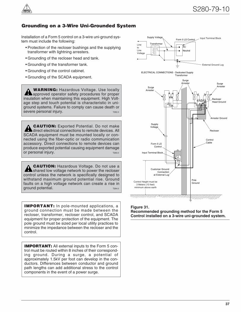
Installation of a Form 5 control on a 3-wire uni-ground sys-tem must include the following:
• Protection of the recloser bushings and the supplyingtransformer with lightning arresters.
• Grounding of the recloser head and tank.
• Grounding of the transformer tank.
• Grounding of the control cabinet.
• Grounding of the SCADA equipment.
S280-79-10
37
!SAFETYFOR LIFE
SurgeArrester
RecloserHead Ground
SurgeArrester
SurgeArrester
Arrester Ground
Recloser
SupplyVoltage
PoleGround
Form 5 LSControl
Customer GroundConnection
at External Lug
GNDNEUHOT
Input Terminal Block
ControlCable
AC
Neutral
Form 5 LS ControlInput Terminal BlockSupply Voltage
Transformer
ELECTRICAL CONNECTIONS - Dedicated Supply Transformer
LinetoLineVoltage
External Ground Lug
NE
UA
C
Control Height must be3 Meters (10 feet)
minimum above earth
Figure 31.Recommended grounding method for the Form 5Control installed on a 3-wire uni-grounded system.
IMPORTANT: All external inputs to the Form 5 con-trol must be routed within 8 inches of their correspond-ing ground. During a surge, a potential ofapproximately 1.5kV per foot can develop in the con-ductors. Differences between conductor and groundpath lengths can add additional stress to the controlcomponents in the event of a power surge.
IMPORTANT: In pole-mounted applications, aground connection must be made between therecloser, transformer, recloser control, and SCADAequipment for proper protection of the equipment. Thepole ground must be sized per local utility practices tominimize the impedance between the recloser and thecontrol.
WARNING: Hazardous Voltage. Use locallyapproved operator safety procedures for proper
insulation when maintaining this equipment. High Volt-age step and touch potential is characteristic in uni-ground systems. Failure to comply can cause death orsevere personal injury. T262.0
!
CAUTION: Exported Potential. Do not makedirect electrical connections to remote devices. All
SCADA equipment must be mounted locally or con-nected using the fiber-optic or radio communicationaccessory. Direct connections to remote devices canproduce exported potential causing equipment damageor personal injury. T263.0
!
CAUTION: Hazardous Voltage. Do not use ashared low voltage network to power the recloser
control unless the network is specifically designed towithstand maximum ground potential rise. Groundfaults on a high voltage network can create a rise inground potential. T264.0
!
Grounding on a 3-Wire Uni-Grounded System
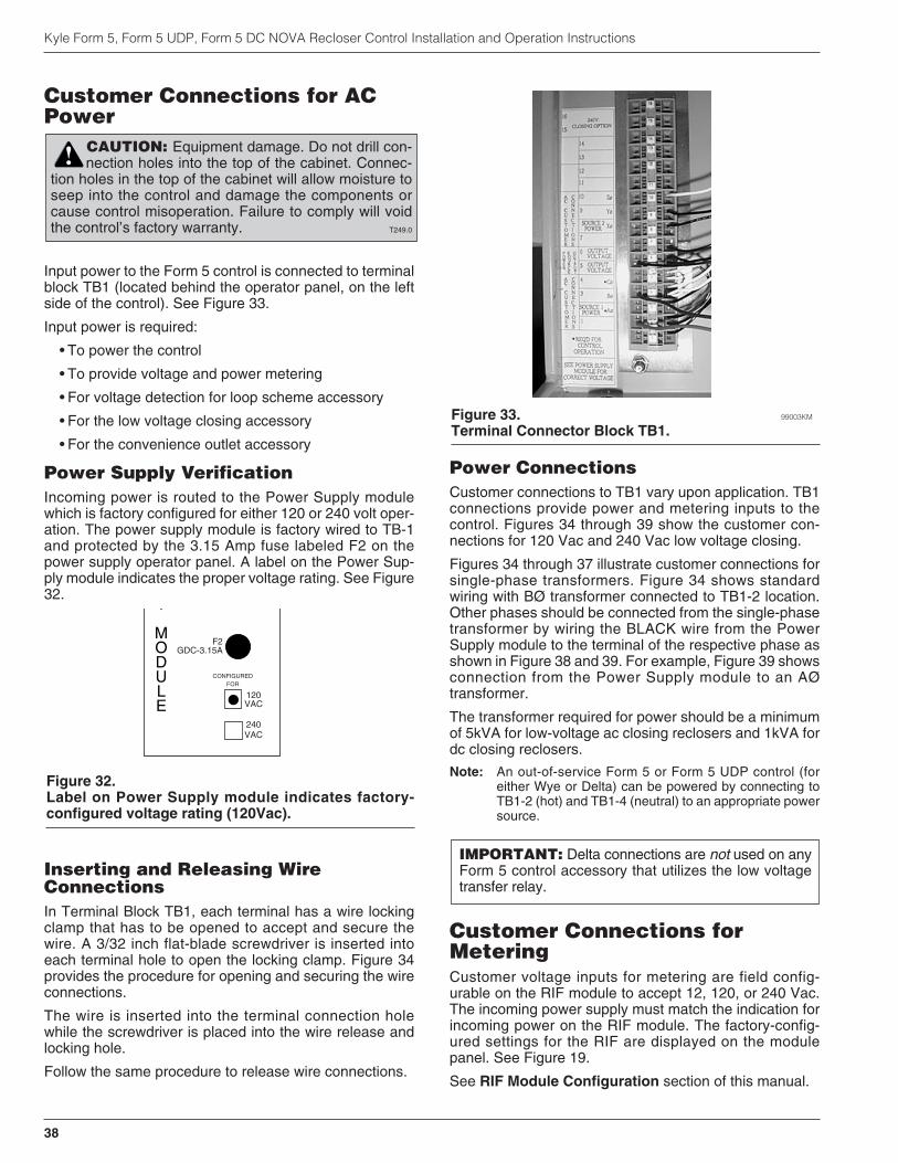
Customer Connections for ACPower
Input power to the Form 5 control is connected to terminalblock TB1 (located behind the operator panel, on the leftside of the control). See Figure 33.
Input power is required:
• To power the control
• To provide voltage and power metering
• For voltage detection for loop scheme accessory
• For the low voltage closing accessory
• For the convenience outlet accessory
Power Supply VerificationIncoming power is routed to the Power Supply modulewhich is factory configured for either 120 or 240 volt oper-ation. The power supply module is factory wired to TB-1and protected by the 3.15 Amp fuse labeled F2 on thepower supply operator panel. A label on the Power Sup-ply module indicates the proper voltage rating. See Figure32.
Inserting and Releasing WireConnectionsIn Terminal Block TB1, each terminal has a wire lockingclamp that has to be opened to accept and secure thewire. A 3/32 inch flat-blade screwdriver is inserted intoeach terminal hole to open the locking clamp. Figure 34provides the procedure for opening and securing the wireconnections.
The wire is inserted into the terminal connection holewhile the screwdriver is placed into the wire release andlocking hole.
Follow the same procedure to release wire connections.
Power ConnectionsCustomer connections to TB1 vary upon application. TB1connections provide power and metering inputs to thecontrol. Figures 34 through 39 show the customer con-nections for 120 Vac and 240 Vac low voltage closing.
Figures 34 through 37 illustrate customer connections forsingle-phase transformers. Figure 34 shows standardwiring with BØ transformer connected to TB1-2 location.Other phases should be connected from the single-phasetransformer by wiring the BLACK wire from the PowerSupply module to the terminal of the respective phase asshown in Figure 38 and 39. For example, Figure 39 showsconnection from the Power Supply module to an AØtransformer.
The transformer required for power should be a minimumof 5kVA for low-voltage ac closing reclosers and 1kVA fordc closing reclosers.
Note: An out-of-service Form 5 or Form 5 UDP control (foreither Wye or Delta) can be powered by connecting toTB1-2 (hot) and TB1-4 (neutral) to an appropriate powersource.
Customer Connections forMeteringCustomer voltage inputs for metering are field config-urable on the RIF module to accept 12, 120, or 240 Vac.The incoming power supply must match the indication forincoming power on the RIF module. The factory-config-ured settings for the RIF are displayed on the modulepanel. See Figure 19.
See RIF Module Configuration section of this manual.
Kyle Form 5, Form 5 UDP, Form 5 DC NOVA Recloser Control Installation and Operation Instructions
38
CAUTION: Equipment damage. Do not drill con-nection holes into the top of the cabinet. Connec-
tion holes in the top of the cabinet will allow moisture toseep into the control and damage the components orcause control misoperation. Failure to comply will voidthe control’s factory warranty. T249.0
!
Figure 33. 99003KM
Terminal Connector Block TB1.
IMPORTANT: Delta connections are not used on anyForm 5 control accessory that utilizes the low voltagetransfer relay.
Y
MODULE
CONFIGUREDFOR
120VAC
240VAC
F2GDC-3.15A
Figure 32.Label on Power Supply module indicates factory-configured voltage rating (120Vac).
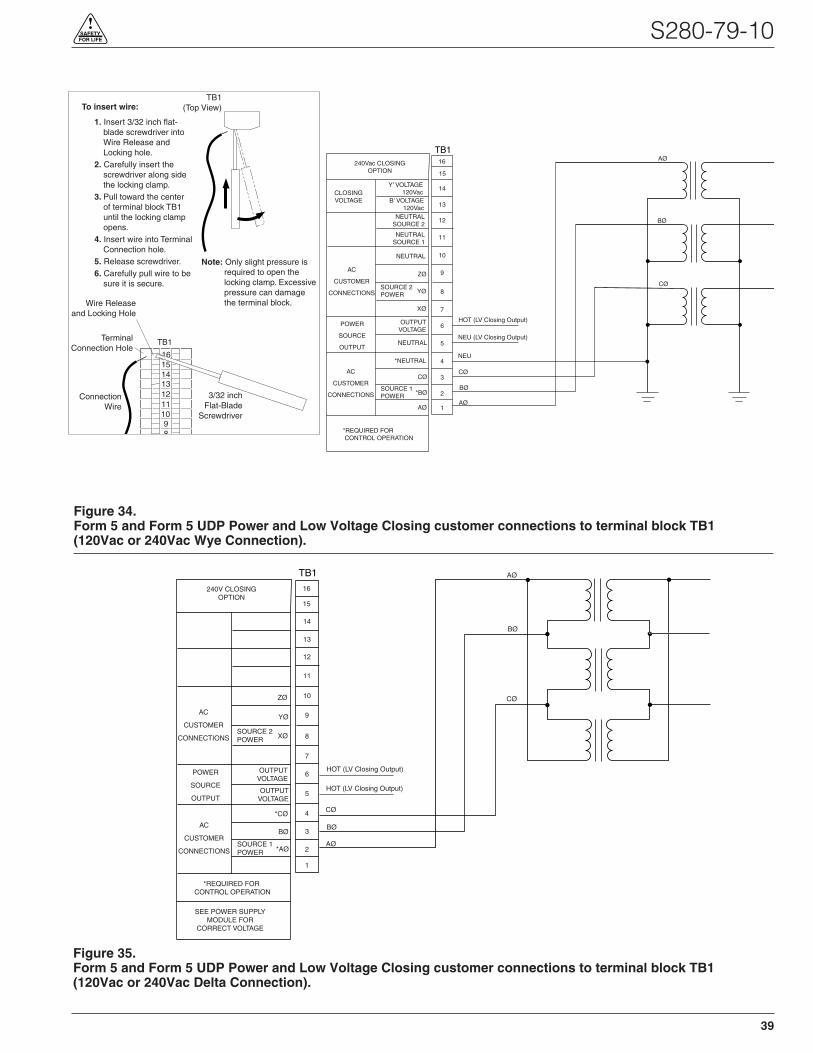
S280-79-10
39
!SAFETYFOR LIFE
TB1
Y' VOLTAGE120Vac
B' VOLTAGE120Vac
CLOSINGVOLTAGE
NEUTRALSOURCE 2
NEUTRALSOURCE 1
AC
CUSTOMER
CONNECTIONS
NEUTRAL
ZØ
YØSOURCE 2POWER
XØ
OUTPUTVOLTAGE
NEUTRAL
*NEUTRAL
POWER
SOURCE
OUTPUT
CØ
*BØ
AØ
AC
CUSTOMER
CONNECTIONSSOURCE 1POWER
*REQUIRED FOR CONTROL OPERATION
1
2
3
4
5
6
7
8
9
10
11
12
13
14
240Vac CLOSINGOPTION
NEU
CØ
BØ
AØ
15
16 AØ
BØ
CØ
NEU (LV Closing Output)
HOT (LV Closing Output)
Figure 34.Form 5 and Form 5 UDP Power and Low Voltage Closing customer connections to terminal block TB1(120Vac or 240Vac Wye Connection).
AC
CUSTOMER
CONNECTIONS
ZØ
YØ
XØSOURCE 2POWER
OUTPUTVOLTAGE
OUTPUTVOLTAGE
*CØ
POWER
SOURCE
OUTPUT
BØ
*AØ
AC
CUSTOMER
CONNECTIONSSOURCE 1POWER
*REQUIRED FOR CONTROL OPERATION
SEE POWER SUPPLYMODULE FOR
CORRECT VOLTAGE
TB1
1
2
3
4
5
6
7
8
9
10
11
12
13
14
CØ
BØ
AØ
240V CLOSINGOPTION
15
16
AØ
BØ
CØ
HOT (LV Closing Output)
HOT (LV Closing Output)
Figure 35.Form 5 and Form 5 UDP Power and Low Voltage Closing customer connections to terminal block TB1(120Vac or 240Vac Delta Connection).
TB1
1615141312111098
1. Insert 3/32 inch flat-blade screwdriver into Wire Release and Locking hole.
2. Carefully insert the screwdriver along side the locking clamp.
3. Pull toward the center of terminal block TB1 until the locking clamp opens.
4. Insert wire into Terminal Connection hole.
5. Release screwdriver.6. Carefully pull wire to be
sure it is secure.
To insert wire:
TerminalConnection Hole
3/32 inchFlat-Blade
Screwdriver
TB1(Top View)
ConnectionWire
Wire Releaseand Locking Hole
Note: Only slight pressure is required to open the locking clamp. Excessive pressure can damage the terminal block.

Kyle Form 5, Form 5 UDP, Form 5 DC NOVA Recloser Control Installation and Operation Instructions
40
AC
CUSTOMER
CONNECTIONS
ZØ
YØ
XØSOURCE 2POWER
OUTPUTVOLTAGE
OUTPUTVOLTAGE
*CØ
POWER
SOURCE
OUTPUT
BØ
*AØ
AC
CUSTOMER
CONNECTIONSSOURCE 1POWER
*REQUIRED FOR CONTROL OPERATION
SEE POWER SUPPLYMODULE FOR
CORRECT VOLTAGE
TB1
1
2
3
4
5
6
7
8
9
10
11
12
13
14
CØ
BØ
AØ
240V CLOSINGOPTION
15
16
AØ
BØ
CØ
HOT (LV Closing Output)
HOT (LV Closing Output)
Figure 36.Form 5 and Form 5 UDP Power and Low Voltage Closing customer connections to terminal block TB1(120Vac or 240Vac Open-Delta Connection).
AC
CUSTOMER
CONNECTIONS
ZØ
YØ
XØSOURCE 2POWER
OUTPUTVOLTAGE
OUTPUTVOLTAGE
CØ
POWER
SOURCE
OUTPUT
*BØ
AØ
AC
CUSTOMER
CONNECTIONSSOURCE 1POWER
*REQUIRED FOR CONTROL OPERATION
TB1
1
2
3
4
5
6
7
8
9
10
11
12
13
14
240V CLOSINGOPTION
15
16
120Vac
Neutral
120Vac
NEU (120Vac LV Closing Output)
HOT (120Vac LV Closing Output)
HOT (240Vac LV Closing Output)†
HOT (240Vac LV Closing Output)†
Y' VOLTAGE120Vac
B' VOLTAGE120Vac
NEUTRALSOURCE 2
NEUTRALSOURCE 1
NEUTRAL
*NEUTRAL
CLOSING
VOLTAGE
† For use with accessories:3-Wire Low-Voltage Closing with receptacle
or3-Wire Low-Voltage Closing with inlet hole for hardwiring
Figure 37.Form 5 and Form 5 UDP Power and Low Voltage Closing customer connections to terminal block TB1(3-wire, 240Vac Connection).

S280-79-10
41
!SAFETYFOR LIFE
TB1
YØ VOLTAGE120Vac
BØ VOLTAGE120Vac
CLOSINGVOLTAGE
NEUTRALSOURCE 2
NEUTRALSOURCE 1
AC
CUSTOMER
CONNECTIONS
NEUTRAL
ZØ
YØSOURCE 2POWER
XØ
OUTPUTVOLTAGE
NEUTRAL
*NEUTRAL
POWER
SOURCE
OUTPUT
CØ
*BØ
AØ
AC
CUSTOMER
CONNECTIONSSOURCE 1POWER
*REQUIRED FOR CONTROL OPERATION
1
2
3
4
5
6
7
8
9
10
11
12
13
14
240Vac CLOSINGOPTION
NEU
BØ
15
16
BØ
NEU (LV Closing Output)
HOT (LV Closing Output)
POWER
SUPPLY
MODULE
CONFIGUREDFOR
120VAC
240VAC
P9
AUX
F2GDC-3.15A
BLK
WHT
**Jumper necessary for use with Low-Voltage Closing Accessory
Jumper**
Figure 38.Form 5 and Form 5 UDP Power and Low Voltage Closing customer connections to terminal block TB1 (Single-Phase Connection, Standard BØ Input).
TB1
Y' VOLTAGE120Vac
B' VOLTAGE120Vac
CLOSINGVOLTAGE
NEUTRALSOURCE 2
NEUTRALSOURCE 1
AC
CUSTOMER
CONNECTIONS
NEUTRAL
ZØ
YØSOURCE 2POWER
XØ
OUTPUTVOLTAGE
NEUTRAL
*NEUTRAL
POWER
SOURCE
OUTPUT
CØ
*BØ
AØ
AC
CUSTOMER
CONNECTIONSSOURCE 1POWER
*REQUIRED FOR CONTROL OPERATION
1
2
3
4
5
6
7
8
9
10
11
12
13
14
240Vac CLOSINGOPTION
NEU
15
16
AØ
NEU (LV Closing Output)
HOT (LV Closing Output)
POWER
SUPPLY
MODULE
CONFIGUREDFOR
120VAC
240VAC
P9
AUX
F2GDC-3.15A
BLK
WHT
AØ
**Jumper necessary for use with Low-Voltage Closing Accessory
Jumper**
Figure 39.Form 5 and Form 5 UDP Power and Low Voltage Closing customer connections to terminal block TB1 (Single-Phase Connection, AØ Input).
Before Placing the Control andthe Recloser into Service
Prior to placing the control and recloser into service, thefollowing installation procedures must be properly com-pleted and verified:
1. Control properly mounted for the installation.
2. Recloser installed according to all locally approvedstandards and practices.
3. Control and recloser properly grounded in accordancewith guidelines in this manual.
4. AC power connected to the control. (AC power LEDindicator is illuminated.)
5. Control battery connected and tested for properoperation.
6. All control programming entered and verified byappropriate personnel.
7. Control clock set to the correct time.
8. Customer connections for remote and supervisoryoperation checked and completed in accordance withproper shielding and surge protection.
9. Control cable properly connected and supported.
Kyle Form 5, Form 5 UDP, Form 5 DC NOVA Recloser Control Installation and Operation Instructions
42
CAUTION: Equipment misoperation. Do notconnect this control to an energized recloser
until all control settings have been properly pro-grammed and verified. Refer to the programminginformation for this control. Failure to comply canresult in control and recloser misoperation, equip-ment damage and personal injury. G110.3
!
WARNING: Hazardous voltage. Recloser andcontrol must be solidly grounded. Follow all
locally approved procedures and safety practices whengrounding this equipment. Improper grounding canresult in contact with high voltage, which will causedeath or severe personal injury. G115.1
!

Testing an Installed ControlThe following tests to determine initial operation of theForm 5 control can be performed while connected to anoperating recloser. These are the only tests performed onan installed, operating control. All other tests described inthis Testing and Troubleshooting section require theForm 5 control to be removed from service, connected toa bypassed recloser, or tested at a location where theproper testing equipment is available.
1. Wake-up the operator panel display by pressing theCHANGE/LAMP TEST button on the control operatorpanel.
2. Scroll through the LCD display messages asdescribed in the LCD Display Messages section ofthese instructions. Refer to Form 5 Control operatorpanel section of this manual.
Check the operational values for currents, voltages,and other metering information.
3. Check that the LED for AC power is illuminated on thecontrol operator panel. This indicates the presence ofAC power.
4. Test battery operation, using the proceduresdescribed in the Battery Test Procedure section ofthese instructions.
Check CPU StatusCheck the operating status of the CPU module. Open thecabinet door and locate the LED indicator (Figure 40).
The LED indicator on the CPU module should flash at arate of one flash per second for normal 60 Hz operation(slightly faster for 50Hz).
Testing With Type MET TesterThe Kyle Type MET Electronic Recloser Control Tester(Figure 41) is used for testing the Form 5 control.
The MET Tester is completely self-contained, includes allnecessary metering and interconnecting cables, and iscapable of performing all required checks and tests froma simple verification of operation to a complete verification
of all operating parameters. Refer to Service InformationS280-76-1 Type MET Electronic Recloser Control TesterOperator Instructions for proper setup and use of the METtester. Refer to Form 5 Control Default Test Proceduresection of this manual for specific tests requiring theKMET Tester.
S280-79-10
43
!SAFETYFOR LIFE
IMPORTANT: The Form 5 recloser control can betaken out of service for testing and placed back intoservice without de-energizing its recloser and interrupt-ing the system. However, during the time the control isout of service, the recloser is inoperative.
CAUTION: Equipment misoperation. Do notconnect this control to an energized recloser
until all control settings have been properly pro-grammed and verified. Refer to the programminginformation for this control. Failure to comply canresult in control and recloser misoperation, equip-ment damage and personal injury. G110.3
!
Figure 40.Form 5 control CPU module.
99002KM
CPU Module(Central Processing Unit)
CPU Module LED Indicator
Figure 41.Kyle Type MET electronic recloser control tester.
010028KM
IMPORTANT: The Form 5 DC NOVA control cannotbe tested with the standard Kyle MET Tester. A junc-tion box accessory for the MET tester is available fortesting the Form 5 DC NOVA control.
TESTING AND TROUBLESHOOTING
IMPORTANT: When the control is open and currentis present, the Trip Fail detection circuit in the Form 5control will activate when the Kyle Type MET testerCALIBRATE switch is ON. Depress and hold theRESET TARGET keypad on the control for 3 secondsto reset the condition.

Closing the Recloser DuringTesting
Electrical Closing—Solenoid-OperatedReclosersLine voltage is required for automatic recloser operationduring testing of reclosers equipped with a closingsolenoid (except for reclosers equipped with the low volt-age closing accessory).
For on-line testing, bypass the recloser, open the load-side disconnects and keep the source-side disconnectsclosed. This will remove the recloser from service, but willkeep line voltage supplied to the closing solenoid (Figure44).
For shop testing, the closing solenoid voltage is suppliedby back-feeding a transformer with a low-side rating equalto the voltage rating of an available power source, and ahigh-side rating equal to the voltage rating of the recloser(Figure 45). A 75kVA transformer of the proper voltagerating with an impedance drop of approximately 3% is sat-isfactory. The ac source must have a comparableimpedance drop.
The closing coil requirement is approximately 200kVAduring the two-to-three cycle closing operation. Thesolenoid coil operating voltage must be maintained at therecloser bushings during the cycle interval the closing coilis energized. This procedure is not used on reclosersequipped with the low-voltage closing accessory.
Electrical Closing—Motor-OperatedReclosers
High-voltage is not required for reclosers utilizing a motor-operated closing mechanism energized from a 230VACpower source. For information on energizing the recloser,refer to the appropriate motor-operated recloser installa-tion manual.
Figure 43 shows a test circuit for motor-operated andsolenoid-closing reclosers with low-voltage closing. Sincethese reclosers require only a 240 Vac source for closing,high-voltage transformer T3 and its protective cage iseliminated. All other equipment is the same as the testequipment shown in Figure 42.
Electrical Closing—NOVA ReclosersType NOVA 3-phase reclosers utilize an interface circuitlocated in the mechanism housing. The electronic inter-face circuit controls the opening and closing signals to themagnetic actuator.
The Dc NOVA Recloser is tested with the dc-to-dc con-verter and 19-pin cable connected to the dc power supply.
Kyle Form 5, Form 5 UDP, Form 5 DC NOVA Recloser Control Installation and Operation Instructions
44
WARNING: Hazardous voltage. Solidly groundall equipment. Failure to comply can result in
death, severe personal injury, and equipment damage.T223.2
!
Figure 43.Suggested test circuit for motor-operated, solenoid-closing reclosers with low-voltage closing.
65
43
21
ElectronicControl
J
G K
H
X W
240 VacPowerSupply
ClosingMotor
T1 T2
240 Vac
VariableAutotransformer240 Vac-20 A
120 Vac
To Ammeterand Relayto operatecycle counter orother timingdevice
Sensing CTs (3)
WARNING: Hazardous voltage. Interconnectsource leads X and Y and ground solidly to the
recloser tank (Figure 45). Do not connect lead Z to anyother phase or mechanical ground. Dangerous voltagesto ground exist on the phase connected to lead Z. Solidlyground all equipment. Failure to comply can result insevere personal injury and/or equipment damage. T224.1
!
Figure 42.Alternate method of producing variable line current(substitute for T2 and W-X circuit in Figures 43 and45).
600:5RecloserBCT ON 600:5 Tap
Note: This test circuit can apply over 800 Amps to the recloser.
Note: Use at least 2/0 cable between bushings.
21
115Vac VariableAutotransformer (10 Amp)
Clamp-OnAmmeter
WARNING: Hazardous voltage. The switchgearand high voltage transformer must be in a test
cage or similar protective device to prevent accidentalcontact with the high voltage parts. Solidly ground allequipment. Failure to comply can result in death,severe personal injury, and equipment damage. T221.3
!

S280-79-10
45
!SAFETYFOR LIFE
3
6
4
T3Y
H
X
Z
VOLTAGE RATING OFRECLOSER CLOSINGSOLENOID COIL
SENSING CTs (3) CLOSINGSOLENOIDCONTACTOR
ROTARYSOLENOID
MAINCONTACTS (S)
G K
A B
E F
TO240 OR480 VACSOURCE
TO240 VACSOURCE
CLOSINGSOLENOIDCOIL
TRIPSOLENOID
CONTROLCABLE RECEPTACLE
W
ELECTRONICCONTROL
TOAMMETER AND RELAY TOOPERATE CYCLE COUNTEROR OTHER TIMING DEVICE
120 VACVARIABLEAUTOTRANSFORMER240 VAC20 AMPS
T2
1 2
5
J
Figure 45.Suggested test circuit for “shop-testing” solenoid-closing reclosers.
5 6
3 4
1 2
C
B
A
BYPASS SWITCHES(CLOSED)
SOURCE SIDEDISCONNECT SWITCHES(CLOSED)
LOAD SIDEDISCONNECT SWITCHES(OPEN)
CLO
SIN
GC
OIL
LOA
D
SO
UR
CES
OU
RC
E
LOA
D
Figure 44.Closing source-side switches of a bypassed “on-line” recloser provides closing solenoid power for automaticoperation during testing.
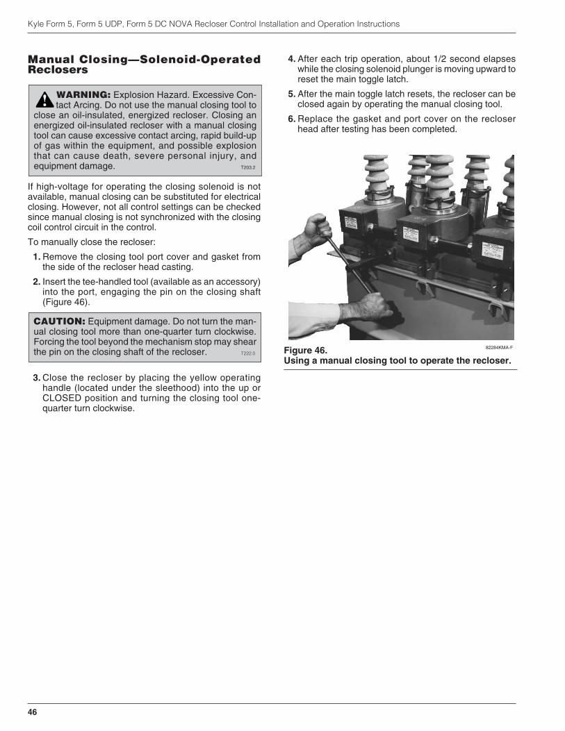
Manual Closing—Solenoid-OperatedReclosers
If high-voltage for operating the closing solenoid is notavailable, manual closing can be substituted for electricalclosing. However, not all control settings can be checkedsince manual closing is not synchronized with the closingcoil control circuit in the control.
To manually close the recloser:
1. Remove the closing tool port cover and gasket fromthe side of the recloser head casting.
2. Insert the tee-handled tool (available as an accessory)into the port, engaging the pin on the closing shaft(Figure 46).
3. Close the recloser by placing the yellow operatinghandle (located under the sleethood) into the up orCLOSED position and turning the closing tool one-quarter turn clockwise.
4. After each trip operation, about 1/2 second elapseswhile the closing solenoid plunger is moving upward toreset the main toggle latch.
5. After the main toggle latch resets, the recloser can beclosed again by operating the manual closing tool.
6. Replace the gasket and port cover on the recloserhead after testing has been completed.
Kyle Form 5, Form 5 UDP, Form 5 DC NOVA Recloser Control Installation and Operation Instructions
46
WARNING: Explosion Hazard. Excessive Con-tact Arcing. Do not use the manual closing tool to
close an oil-insulated, energized recloser. Closing anenergized oil-insulated recloser with a manual closingtool can cause excessive contact arcing, rapid build-upof gas within the equipment, and possible explosionthat can cause death, severe personal injury, andequipment damage. T203.2
!
CAUTION: Equipment damage. Do not turn the man-ual closing tool more than one-quarter turn clockwise.Forcing the tool beyond the mechanism stop may shearthe pin on the closing shaft of the recloser. T222.0 Figure 46.
Using a manual closing tool to operate the recloser.
82284KMA-F

Use this procedure to test the Form 5 control with factorydefault control settings. Follow all cautions and warningsin these service instructions.
Before installation on an active feeder, the Form 5 con-trol’s final control settings must be fully tested using anappropriate test procedure. The Form 5 Control DefaultTest Sheet follows these instructions. The Form 5 ControlDefault Test Sheet Optimal Values gives the optimal val-ues for the test results.
When performing these tests, change the Form 5 panelsettings by first pressing the CHANGE button and thenpressing the button of the function to be changed.
Initial Settings1. Apply 120 (240) Vac to the control phase B and neu-
tral for standard controls.
2. Plug in battery.
3. Verify control is programmed for all default settings.
• Phase Minimum Trip is set to 100 amps.
• Ground Minimum Trip is set to 50 amps.
4. Disable Sequence Coordination in normal profileusing personal computer (PC).
5. Activate COLD LOAD PICKUP BLOCKED (LED is on)on Form 5 display panel.
6. Activate GROUND TRIP BLOCK (LED is on) on Form5 display panel.
Test Battery Circuitry
1. Press BACK button on display panel until Battery TestScreen 31 appears.
2. Record values for all settings.
3. Press CHANGE button on the display panel.
4. Press BATTERY TEST button on display panel.
5. Record values for all readings.
Test Phase Minimum Trip Values1. Verify Ground Trip Block LED is on.
2. Set KMET Phase Selector S5 to A.
3. Set KMET switch S4 to 300 milliampere range.
4. Set KMET Variac TR1 to zero.
5. Set KMET switch S2 to test fault current position.
6. Press the TRIP button on the display panel.
7. Press the CLOSE button on the display panel.
8. Slowly raise TR1 until Above Minimum Trip LED is on,on display panel. Control should trip out quickly forload currents above 105 milliamperes. Record value.
9. Repeat steps 4 – 8 for phases B and C (move KMETS5 to B, then C).
10. Change Form 5 control from Normal Profile to Alter-nate Profile 1.
11. Verify Cold Load Pickup Blocked (LED is on) on thedisplay panel.
12. Repeat steps 2 – 9 for Form 5 Alternate Profiles 1, 2,and 3. The control is programmed to trip out at 200milliamperes on the Alternate 1, 2, and 3 Profiles.
Note: If Cold Load Pickup LED is off, the control will trip on atime delayed Time Current Curve with two trips to lock-out for 30 seconds after closing in the control, per thedefault Cold Load Pickup control settings.
Note: If Alternate Profiles 1, 2, and 3 have the sequence coor-dination function enabled while testing the Form 5 con-trol minimum trip values, it may result in the controlskipping past the fast TCC curves during the test forminimum trip. The control will then lock out on thedelayed TCC curves.
Note: If the Form 5 control has Switch Mode rather than Pro-file 3, the control will indicate current Above MinimumTrip, but will not trip out.
S280-79-10
47
!SAFETYFOR LIFE
CAUTION: Equipment misoperation. Do not con-nect this control to an energized recloser until all
control settings have been properly programmed andverified. Refer to the programming information for thiscontrol. Failure to comply can result in control andrecloser misoperation, equipment damage, and per-sonal injury. G110.3
!
IMPORTANT: The Form 5 recloser control can betaken out of service for testing and placed back intoservice without de-energizing its recloser and interrupt-ing the system. However, during the time the control isout of service, the recloser is inoperative.
IMPORTANT: The Form 5 DC NOVA control can notbe tested with the standard Kyle MET Tester. A junctionbox accessory for the MET tester is availble for testingthe Form 5 DC NOVA control.
FORM 5 CONTROL DEFAULT TEST PROCEDURE
IMPORTANT: The Battery Test procedure requireslarge current drain. Overuse of this procedure will drainthe battery.
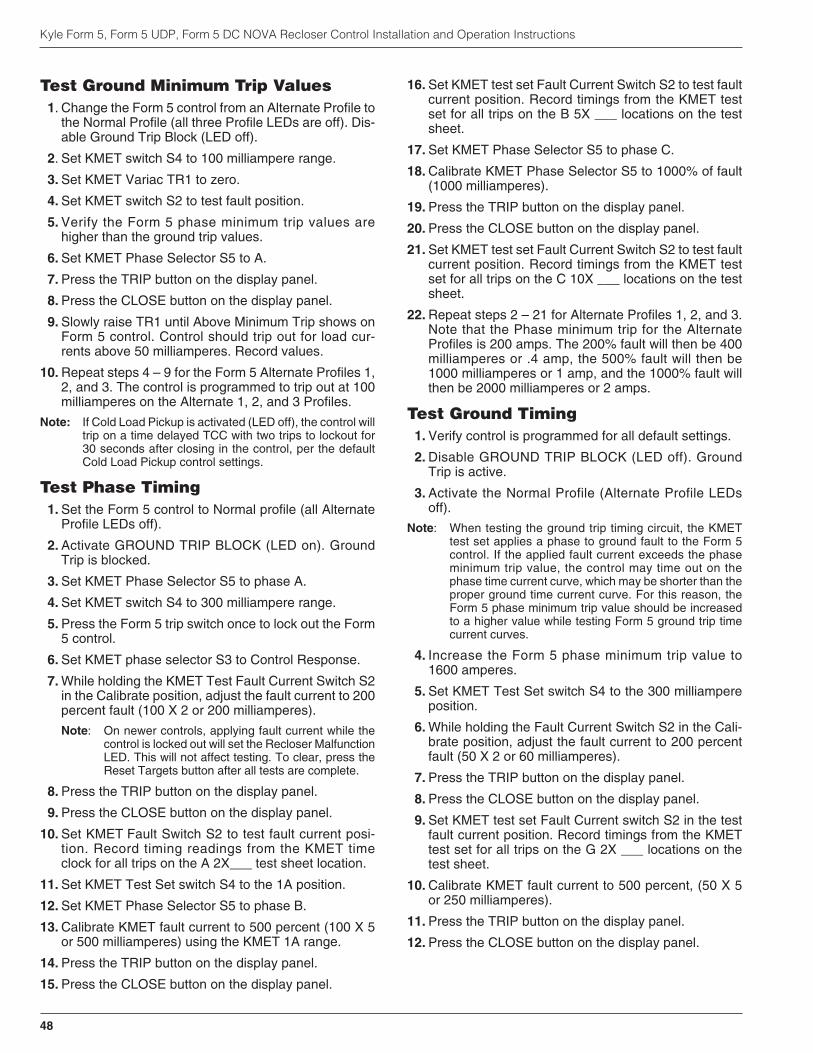
Test Ground Minimum Trip Values1. Change the Form 5 control from an Alternate Profile to
the Normal Profile (all three Profile LEDs are off). Dis-able Ground Trip Block (LED off).
2. Set KMET switch S4 to 100 milliampere range.
3. Set KMET Variac TR1 to zero.
4. Set KMET switch S2 to test fault position.
5. Verify the Form 5 phase minimum trip values arehigher than the ground trip values.
6. Set KMET Phase Selector S5 to A.
7. Press the TRIP button on the display panel.
8. Press the CLOSE button on the display panel.
9. Slowly raise TR1 until Above Minimum Trip shows onForm 5 control. Control should trip out for load cur-rents above 50 milliamperes. Record values.
10. Repeat steps 4 – 9 for the Form 5 Alternate Profiles 1,2, and 3. The control is programmed to trip out at 100milliamperes on the Alternate 1, 2, and 3 Profiles.
Note: If Cold Load Pickup is activated (LED off), the control willtrip on a time delayed TCC with two trips to lockout for30 seconds after closing in the control, per the defaultCold Load Pickup control settings.
Test Phase Timing1. Set the Form 5 control to Normal profile (all Alternate
Profile LEDs off).
2. Activate GROUND TRIP BLOCK (LED on). GroundTrip is blocked.
3. Set KMET Phase Selector S5 to phase A.
4. Set KMET switch S4 to 300 milliampere range.
5. Press the Form 5 trip switch once to lock out the Form5 control.
6. Set KMET phase selector S3 to Control Response.
7. While holding the KMET Test Fault Current Switch S2in the Calibrate position, adjust the fault current to 200percent fault (100 X 2 or 200 milliamperes).
Note: On newer controls, applying fault current while thecontrol is locked out will set the Recloser MalfunctionLED. This will not affect testing. To clear, press theReset Targets button after all tests are complete.
8. Press the TRIP button on the display panel.
9. Press the CLOSE button on the display panel.
10. Set KMET Fault Switch S2 to test fault current posi-tion. Record timing readings from the KMET timeclock for all trips on the A 2X___ test sheet location.
11. Set KMET Test Set switch S4 to the 1A position.
12. Set KMET Phase Selector S5 to phase B.
13. Calibrate KMET fault current to 500 percent (100 X 5or 500 milliamperes) using the KMET 1A range.
14. Press the TRIP button on the display panel.
15. Press the CLOSE button on the display panel.
16. Set KMET test set Fault Current Switch S2 to test faultcurrent position. Record timings from the KMET testset for all trips on the B 5X ___ locations on the testsheet.
17. Set KMET Phase Selector S5 to phase C.
18. Calibrate KMET Phase Selector S5 to 1000% of fault(1000 milliamperes).
19. Press the TRIP button on the display panel.
20. Press the CLOSE button on the display panel.
21. Set KMET test set Fault Current Switch S2 to test faultcurrent position. Record timings from the KMET testset for all trips on the C 10X ___ locations on the testsheet.
22. Repeat steps 2 – 21 for Alternate Profiles 1, 2, and 3.Note that the Phase minimum trip for the AlternateProfiles is 200 amps. The 200% fault will then be 400milliamperes or .4 amp, the 500% fault will then be1000 milliamperes or 1 amp, and the 1000% fault willthen be 2000 milliamperes or 2 amps.
Test Ground Timing1. Verify control is programmed for all default settings.
2. Disable GROUND TRIP BLOCK (LED off). GroundTrip is active.
3. Activate the Normal Profile (Alternate Profile LEDsoff).
Note: When testing the ground trip timing circuit, the KMETtest set applies a phase to ground fault to the Form 5control. If the applied fault current exceeds the phaseminimum trip value, the control may time out on thephase time current curve, which may be shorter than theproper ground time current curve. For this reason, theForm 5 phase minimum trip value should be increasedto a higher value while testing Form 5 ground trip timecurrent curves.
4. Increase the Form 5 phase minimum trip value to1600 amperes.
5. Set KMET Test Set switch S4 to the 300 milliampereposition.
6. While holding the Fault Current Switch S2 in the Cali-brate position, adjust the fault current to 200 percentfault (50 X 2 or 60 milliamperes).
7. Press the TRIP button on the display panel.
8. Press the CLOSE button on the display panel.
9. Set KMET test set Fault Current switch S2 in the testfault current position. Record timings from the KMETtest set for all trips on the G 2X ___ locations on thetest sheet.
10. Calibrate KMET fault current to 500 percent, (50 X 5or 250 milliamperes).
11. Press the TRIP button on the display panel.
12. Press the CLOSE button on the display panel.
Kyle Form 5, Form 5 UDP, Form 5 DC NOVA Recloser Control Installation and Operation Instructions
48

13. Set KMET test set Fault Current switch S2 in the testfault current position. Record timings from the KMETtest set for all trips on the G 5X ___ locations on thetest sheet.
14. Set KMET Test Set switch S4 to the 1A position.
15. Calibrate KMET fault current to 1000 percent, (50 X 10or 500 milliamperes).
16. Press the TRIP button on the display panel.
17. Press the CLOSE button on the display panel.
18. Set KMET test set Fault Current switch S2 in the testfault current position. Record timings from the KMETtest set for all trips on the G 10X ___ locations on thetest sheet.
19. Repeat steps 4 – 18 for Alternate Profiles 1, 2, and 3.Note that the ground minimum trip for the AlternateProfiles is 100 amps. The 200% fault will then be 200milliamperes, the 500% fault will then be 500 mil-liamperes, and the 1000% fault will then be 1000 mil-liamperes or 1 amps.
20. Return the Normal Profile Phase Minimum Trip Valueto the pretest value, 100 amps.
Test Non-Reclose1. Activate NON-RECLOSING (LED on).
2. Activate GROUND TRIP BLOCK (LED on).
3. Set KMET Phase Selector switch S5 to phase A.
4. Set Form 5 control to Normal Profile (all Alternate Pro-file LEDs off).
5. Adjust fault current to 200 percent or 200 mil-liamperes.
6. Press the TRIP button on the display panel.
7. Press the CLOSE button on the display panel.
8. Set KMET test set Fault Current Switch S2 to faultposition.
9. Control should trip once, then indicate open and lock-out. Record time value.
10. Disable NON-RECLOSE (LED off).
11. Repeat steps 5 – 8, to lockout. Record time value.
Test Cold Load Pickup Blocked1. Disable COLD LOAD PICKUP BLOCKED (LED off).
2. CLOSE the Form 5 control.
3. Adjust fault current to 200 percent or 200 mil-liamperes.
4. Within 30 seconds of Step 3, set KMET test set FaultCurrent Switch S2 to fault position.
5. Control should trip twice on slow TCC curve, then indi-cate open and lockout. Record timing value.
6. Activate COLD LOAD PICKUP BLOCKED (LED on).
7. Repeat steps 2 – 4. Record value.
Test Fast Trips Disabled1. Activate FAST TRIPS DISABLED (LED on).
2. CLOSE the Form 5 control.
3. Adjust fault current to 200 percent or 200 mil-liamperes.
4. Set KMET test set Fault Current Switch S2 to faultposition.
5. Control should trip two times to lockout, on all slowTCCs, then indicate OPEN and lockout. Record value.
6. Deactivate Fast Trips Disabled (LED off).
7. Repeat steps 2 -4. Control should trip on two fast, twoslow TCCs. Record values.
Test Hot Line Tag1. CLOSE the Form 5 control.
2. Activate HOT LINE TAG (LED on).
3. Adjust fault current to 200 percent or 200 mil-liamperes.
4. Set KMET test set Fault Current Switch S2 to faultposition.
5. Control should trip out once on the 101 TCC curve,then indicate open and lockout. Record value.
6. Verify that it is not possible to close the Form 5 control.
7. Deactivate HOT LINE TAG (LED off).
8. Verify that you can CLOSE the Form 5 control.
Test Reclose1. Set KMET selector switch S3 to Control Reclose
Reset.
2. Reset the KMET Time Clock if required.
3. Adjust fault current to 200 percent or 200 mil-liamperes.
4. Set KMET test set Fault Current Switch S2 to faultposition.
5. After trip, turn fault switch S2 off.
6. Record reclose time.
7. Repeat steps 2 – 6 until control locks out.
S280-79-10
49
!SAFETYFOR LIFE

Test Close Circuit Disable FuseThis test is only applicable to Form 5 LS controls and stan-dard Form 5 controls below Serial Number 3000.
1. Set KMET Fault Switch S2 to OFF.
2. CLOSE the Form 5 control.
3. Remove Close Circuit Disable fuse.
4. Adjust fault current to 200 percent or 200 mil-liamperes.
5. Set KMET test set Fault Current Switch S2 to faultposition. The control will trip once.
6. Verify that it is not possible to close the Form 5 control.
7. Replace Close Circuit Disable fuse.
8. Verify it is now possible to CLOSE the Form 5 control.
Verify Instantaneous DemandMetering
1. Enable GROUND TRIP BLOCK (LED on).
2. Set KMET switch S2 to OFF.
3. Set KMET Phase Selector S5 to A.
4. Set KMET Variac to zero.
5. Set KMET switch S4 to the 100 milliampere range.
6. CLOSE Form 5 control.
7. Set KMET switch S2 to ON.
8. Set KMET Variac to read 80 milliamperes.
9. Scroll the Form 5 LCD screen to screen 1.
10. Verify Instantaneous metering on Phase A andGround reads 80 milliamperes.
11. Set KMET Phase Selector S5 to B.
12. Verify Instantaneous metering on Phase B andGround reads 80 milliamperes.
13. Set KMET Phase Selector S5 to C.
14. Verify Instantaneous metering on Phase C andGround reads 80 milliamperes.
Kyle Form 5, Form 5 UDP, Form 5 DC NOVA Recloser Control Installation and Operation Instructions
50

S280-79-10
51
!SAFETYFOR LIFE
Form 5 Control Default Test Optimal Values
2. Volts 28.0 2.6 Volts 28.0
Battery Circuitry MA 35 2.6 MA 550
Volts 27.0 2.6 volts 24.2
3. Normal Profile Phase A Amps Phase B Amps Phase C Amps
100.5 100.3 100.7
Phase Profile #1 Phase A Amps Phase B Amps Phase C Amps
Minimum Trip 200.9 200.2 200.5
Profile #2 Phase A Amps Phase B Amps Phase C Amps
200.9 200.2 200.5
Profile #3 Phase A Amps Phase B Amps Phase C Amps
200.9 200.2 200.5
4. Normal Ground Amps 50.1
Ground Profile #1 Ground Amps 100.3
Minimum Trip Profile #2 Ground Amps 100.3
Profile #3 Ground Amps 100.3
5. Trip to Lockout Sequence 1st 2nd 3rd 4th
Phase Timing Normal Phase A 2X 0.161 0.164 1.416 1.421
Phase B 5X 0.018 0.017 0.278 0.280
Phase C 10X 0.016 0.014 0.088 0.086
Profile #1 Phase A 2X 0.153 0.154 1.443 1.441
Phase B 5X 0.015 0.014 0.273 0.275
Phase C 10X 0.011 0.009 0.087 0.087
Profile #2 Phase A 2X 0.153 0.154 1.443 1.441
Phase B 5X 0.015 0.014 0.273 0.275
Phase C 10X 0.011 0.009 0.087 0.087
Profile #3 Phase A 2X 0.153 0.154 1.443 1.441
Phase B 5X 0.015 0.014 0.273 0.275
Phase C 10X 0.011 0.009 0.087 0.087

Kyle Form 5, Form 5 UDP, Form 5 DC NOVA Recloser Control Installation and Operation Instructions
52
Form 5 Control Default Test Optimal Values
6. Trip Sequence 1st 2nd 3rd 4th
Ground Timing Normal Ground 2X 0.214 0.212 3.894 3.896
Ground 5X 0.012 0.016 1.097 1.099
Ground 10X 0.008 0.014 0.652 0.653
Profile #1 Ground 2X 0.214 0.212 3.894 3.896
Ground 5X 0.012 0.016 0.952* 0.954*
Ground 10X 0.008 0.014 0.280* 0.276*
Profile #2 Ground 2X 0.214 0.212 3.984 3.896
Ground 5X 0.012 0.016 0.952* 0.954*
Ground 10X 0.008 0.014 0.280* 0.276*
Profile #3 Ground 2X 0.214 0.212 3.894 3.896
Ground 5X 0.012 0.016 0.952* 0.954*
Ground 10X 0.008 0.014 0.280* 0.276*
7. Enabled Phase 2X 0.153 lockout lockout lockout
Non-Reclose Disabled Phase 2X 0.152 0.153 1.420 1.433
8. Cold Load Block Off Phase 2X 1.420 1.433 lockout lockout
PickUp Blocked Block On 0.158 0.154 1.420 1.433
9. Fast Trips Enabled Phase 2X 1.419 1.422 lockout lockout
Disabled Phase 2X 0.155 0.156 1.418 1.424
10. No Reclose Phase 2X 0.014 lockout lockout lockout
Hot Line Tag Enabled Phase 2X 0.155 0.156 1.148 1.424
11. Reclose Sequence 1st 2nd 3rd 4th
Test Reclose Reclose Times 1.975 1.974 4.968 lockout
12. Fuse Out Can’t Close? Yes No
Close Circuit XXX
Disable Fuse Fuse In Can Close? Yes No
XXX
13. Instantaneous Phase A Phase B Phase C
Demand Metering Amps 80 Amps 81 Amps 80
*Refer to the Test Ground Timing section of this manual.

S280-79-10
53
!SAFETYFOR LIFE
Form 5 Control Default Test SheetDate: Serial No:
2. Volts 2.6 Volts
Battery Circuitry MA 2.6 MA
Volts 2.6 volts
3. Normal Profile Phase A Amps Phase B Amps Phase C Amps
Phase Profile #1 Phase A Amps Phase B Amps Phase C Amps
Minimum Trip
Profile #2 Phase A Amps Phase B Amps Phase C Amps
Profile #3 Phase A Amps Phase B Amps Phase C Amps
4. Normal Ground Amps
Ground Profile #1 Ground Amps
Minimum Trip Profile #2 Ground Amps
Profile #3 Ground Amps
5. Trip to Lockout Sequence 1st 2nd 3rd 4th
Phase Timing Normal Phase A 2X
Phase B 5X
Phase C 10X
Profile #1 Phase A 2X
Phase B 5X
Phase C 10X
Profile #2 Phase A 2X
Phase B 5X
Phase C 10X
Profile #3 Phase A 2X
Phase B 5X
Phase C 10X

Kyle Form 5, Form 5 UDP, Form 5 DC NOVA Recloser Control Installation and Operation Instructions
54
Form 5 Control Default Test Sheet
6. Trip Sequence 1st 2nd 3rd 4th
Ground Timing Normal Ground 2X
Ground 5X
Ground 10X
Profile #1 Ground 2X
Ground 5X
Ground 10X
Profile #2 Ground 2X
Ground 5X
Ground 10X
Profile #3 Ground 2X
Ground 5X
Ground 10X
7. Enabled Phase 2X lockout lockout lockout
Non-Reclose Disabled Phase 2X
8. Cold Load Block Off Phase 2X lockout lockout
PickUp Blocked Block On
9. Fast Trips Enabled Phase 2X lockout lockout
Disabled Phase 2X
10. No Reclose Phase 2X
Hot Line Tag Enabled Phase 2X
11. Reclose Sequence 1st 2nd 3rd 4th
Test Reclose Reclose Times
12. Fuse Out Can’t Close? Yes No
Close Circuit
Disable Fuse Fuse In Can Close? Yes No
13.Instantaneous Phase A Phase B Phase C
Demand Metering Amps Amps Amps
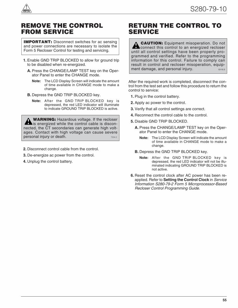
REMOVE THE CONTROLFROM SERVICE
1. Enable GND TRIP BLOCKED to allow for ground tripto be disabled when re-energized.
A. Press the CHANGE/LAMP TEST key on the Oper-ator Panel to enter the CHANGE mode.
Note: The LCD Display Screen will indicate the amountof time available in CHANGE mode to make achange.
B. Depress the GND TRIP BLOCKED key.
Note: After the GND TRIP BLOCKED key isdepressed, the red LED indicator will illuminateto indicate GROUND TRIP BLOCKED is active.
2. Disconnect control cable from the control.
3. De-energize ac power from the control.
4. Unplug the control battery.
RETURN THE CONTROL TOSERVICE
After the required work is completed, disconnect the con-trol from the test set and follow this procedure to return thecontrol to service:
1. Plug in the control battery.
2. Apply ac power to the control.
3. Verify that all control settings are correct.
4. Reconnect the control cable to the control.
5. Disable GND TRIP BLOCKED.
A. Press the CHANGE/LAMP TEST key on the Oper-ator Panel to enter the CHANGE mode.
Note: The LCD Display Screen will indicate the amountof time available in CHANGE mode to make achange.
B. Depress the GND TRIP BLOCKED key.
Note: After the GND TRIP BLOCKED key isdepressed, the red LED indicator will not be illu-minated indicating GROUND TRIP BLOCKED isnot active.
6. Reset the control clock after AC power has been re-applied. Refer to Setting the Control Clock in ServiceInformation S280-79-2 Form 5 Microprocessor-BasedRecloser Control Programming Guide.
S280-79-10
55
!SAFETYFOR LIFE
IMPORTANT: Disconnect switches for ac sensingand power connections are necessary to isolate theForm 5 Recloser Control for testing and servicing.
WARNING: Hazardous voltage. If the recloseris energized while the control cable is discon-
nected, the CT secondaries can generate high volt-ages. Contact with high voltage can cause severepersonal injury or death. T204.2
!
CAUTION: Equipment misoperation. Do notconnect this control to an energized recloser
until all control settings have been properly pro-grammed and verified. Refer to the programminginformation for this control. Failure to comply canresult in control and recloser misoperation, equip-ment damage, and personal injury. G110.3
!
Replacement KitsReplacement kits for the Kyle Form 5 Control are avail-able through the factory Service Department. To orderthese kits, refer to the Replacement Parts price list for cat-alog numbers and pricing. Contact your Cooper PowerSystems representative for additional information andordering procedures.
Factory-Authorized ServiceCentersFactory-authorized service centers are located through-out the continental United States to provide maintenance,repair and testing services for Kyle controls and reclosers.For further information, contact your Cooper Power Sys-tems representative.
Factory Maintenance ClassesThe factory service department offers a basic testing andtroubleshooting course for the Form 5 Microprocessor-Based Electronic Recloser Control and Reclosers. Thiscourse, taught by experienced service technicians, isheld at the factory‘s in-house training facility. For addi-tional information, contact your Cooper Power Systemsrepresentative.
Type MET Recloser Control TesterA 30-minute video cassette program, KSPV7 Kyle® TypeMET Electronic Recloser Control Tester Operation andTesting Procedures is available as a supplemental train-ing aid for service personnel.
Kyle Form 5, Form 5 UDP, Form 5 DC NOVA Recloser Control Installation and Operation Instructions
56 KDL5/05
1045 Hickory StreetPewaukee, WI 53072www.cooperpower.com
©2005 Cooper Power Systems or its affiliates.Kyle® is a registered trademark of Cooper Power Systems or its affiliates.
KA2048-476 Rev: 02
!SAFETYFOR LIFE
ADDITIONAL INFORMATION
CAUTION: This equipment requires routineinspection and maintenance to ensure proper
operation. If it is not maintained, it can fail to operateproperly. Improper operation can cause equipmentdamage and possible personal injury. G105.1
!


![Finale 2006 - [S280 Glory to God Brass BEV]cuthbertpraise.com/files/S280_SCORE.pdfGlory to God (Brass Ensemble Version) S280 Canticle 20 ©2006 CuthbertPraise! #S280 Episcopal Hymnal](https://static.fdocuments.us/doc/165x107/60056d6ed54e1c4229237c69/finale-2006-s280-glory-to-god-brass-bev-glory-to-god-brass-ensemble-version.jpg)