KW960 DIGITAL TO SYNCHRO OR RESOLVER INTERFACEamimarine.net/site/pdfs/15_tech_manual.pdf · DIGITAL...
20
KW960 DIGITAL TO SYNCHRO OR RESOLVER INTERFACE AMI MARINE (UK) LTD Manual KW960 Iss01 Rev10.doc © This Manual and the information contained therein is the property of AMI Marine (UK) Ltd. It must not be reproduced or otherwise disclosed without prior consent in writing from AMI Marine (UK) Ltd
Transcript of KW960 DIGITAL TO SYNCHRO OR RESOLVER INTERFACEamimarine.net/site/pdfs/15_tech_manual.pdf · DIGITAL...
KW960
DIGITAL TO SYNCHRO OR RESOLVER INTERFACE
AMI MARINE (UK) LTD
Manual KW960 Iss01 Rev10.doc
© This Manual and the information contained therein is the property of AMI Marine (UK) Ltd. It must not be reproduced or otherwise disclosed without prior consent in writing from AMI Marine (UK) Ltd

Page 2 of 20
This page intentionally blank

Page 3 of 20
Document
Issue Date Modification Number (where applicable)
Brief Record of Change and Reason for Change Iss01 Rev01 15.08.02 Original Issue
Rev02 02.03.05 Version C
Rev03 04.05.06 Version D
Rev04 16.05.08 Change of address
Rev05 03.09.10 Insert 400Hz information
Rev06 14.12.10 Insert High Voltage 400Hz information
Rev07 17.03.11 Addition of the new high accuracy option and the updated TF960 400Hz option
Rev08 26.04.11 Corrected errors in text for the TF960 400Hz option
Rev09 08.12.11 Added new option for Ground Speed VTG
Rev10 02.08.13 Added new option for High Speed
Rev11 07.03.14 Change of address
NOTE: All alterations must be verified by re-authorisation and approval of the
complete document.

Page 4 of 20
This page intentionally blank
Page 5 of 20
TECHNICAL MANUAL CONTENTS Introduction. .............................................................................................................. 7 Specifications: ........................................................................................................... 7
Setting to work: ...................................................................................................... 8 AD400 Low Voltage 400 Hz Adaptor. ................................................................... 10 PS400 400 Hz Power Inverter. ............................................................................. 11 TF960 Step Up Transformer Adaptor. .................................................................. 12 TF960 using External 115V 400Hz as the main AC supply. ................................. 13
Testing the KW960: .......................................................................................... 15 Board Layout. ...................................................................................................... 17
AMI MARINE (UK) LTD Unit 9, Crosshouse Centre Crosshouse Road Southampton SO14 5GZ United Kingdom Tel No: +44 (0) 23 8048 0450 Fax No: +44 (0) 23 8065 1126 Email: [email protected] Web: www.amimarine.net

Page 6 of 20
This page intentionally blank
Page 7 of 20
Introduction. The interface receives data by NMEA 0183 and generates a low power synchro, resolver (or sine-cosine) output. The interface will drive typically one or two synchro motors, or numerous electronic interfaces. Applications are to generate gyro compass or wind instrument synchro signals. Log speed and GPS speed to synchro etc is possible. Applications include the retro-fitting of a gyro without a synchro output. The KW960 has a number of different ratios from 1:1 to 360:1. Two KW960s can be used for a coarse and fine servo system as found on military vessels, and with certain gyro compass transmission systems. The adjustable voltage output is about 40 volts maximum, so it can be used for an Anschutz repeater and others directly. For driving known coarse/fine servo systems the KW960’s standard 50v reference output is found sufficient. The synchro frequency is that of the main power input, so for 400 Hz you need a 400 Hz power source or a converter such as the AMI Marine AD400. For obtaining 115volt ref, 90 volt signals you a step up transformer adaptor. This is an optional; extra, don’t forget to order it. AMI also make the KW903-SX which is a high power version of the 960 for gyro transmission at 50/60 Hz. Specifications: Input: NMEA 0183 heading $HEHDT or $GPHDT. or wind sentence $WIMWV. Other options possible with EPROM change. Version for longitudinal bow water speed from $VMVBW,x.x,,A, etc sentence. Version for pitch or roll. $IIXDR,A,x.x,D,A,x.x,D, etc sentence. Version for Ground Speed VTG 0 to 96Knots for 1 revolution. Power: 115/230v 50 to 400 Hz at 10 VA approx. (Transformer secondary 2x25 volts) Output: Synchro. Nominal 10 to 40 volts line to line maximum, adjustable by potentiometer. 5VA total. Virtual centre of 3-phase synchro output is at ground. Reference. Nominal 25 or 50 volts, jumper selected.
(An additional transformer adapter is needed for 115v reference, 90v signals.) Reference frequency is that of the power input. Reference output is that of the transformer secondary.
Resolver. Nominal 20 volts max. (EPROM specific version.)
Accuracy: +/- 0.2 with the DSCP1 (Gyro only) or +/- 1 degree of synchro position.
This accuracy applies to all ratios. High accuracy DSCP1 IC12, 13 & 14 fitted. Standard IC4, 5 & 6 fitted.
Ratio Options: Jumper J2 = 1 = 1:1 ratio. J2 = 0 = the ratio as set in EPROM location.
Available ratios 9:1, 10:1, 30:1, 36:1, 90:1, 180:1, 360:1 Dual Log Speed: J2 = 1 = 200 kts/rev. J2 = 0 = 5 knots/rev or 100 knots/rev. Enclosures: Standard system 300 x 200 x 155.
For a dual (coarse & fine)(pitch & roll) system 400 x 300 x 155.

Page 8 of 20
Principles of generating the output: The input angle is read from the data input. The program rotates the synchro output to any new position, going through all digital states towards it, not just jumping there. This is to attempt to move a synchro smoothly, reducing the jerk caused by any sudden jump of the input. The rotation rate is adjustable by a screwdriver switch from about 2 to 10 degrees per second.
There are 360 “steps” per revolution in the 1:1 mode. The graph shows the relationship of the three voltages. At 60 degree intervals two phases become equal and opposite with the third phase being zero. Measured from ground to the S1, S2, S3 outputs, add 30 degrees to the angle first.
Setting to work: Power SK6: Set the power switch 115/230v as required. (230v Default) The KW960 will suffer a massive burn out if you apply the wrong voltage. This is not covered by warranty. The KW960 will operate from 115 or 220v 50/60 Hz and has been used on 400 Hz. On 400 Hz it gives 400 Hz synchro reference and phases output. NMEA 0183 Input SK2: For heading J3 = 0, For Wind J3 = 1. For the log speed version a different EPROM is used. J3 is not used. For pitch and roll another EPROM version is used. J3 is not used. Synchro or Resolver Sine/Cosine output SK1: The EPROM must be configured for the output. Location 5C = 00 Hex = resolver or sin-cosine. If 5C is non zero the output is synchro. Synchro Output Ratio: J2 = 1 = 1:1 ratio J2 = 0 = ratio set by location 54 Hex. Values are Hex. 00 = 360:1, 1 rev per degree, the commonest synchro transmission ratio. FF = 180:1. 90 = 90:1. 36 = 36:1. 30 = 30:1. 10 = 10:1. 09 = 9:1 Resolver Sine/Cosine output: Ground E is common, S1 = Sine, S2 = Cosine, S3 = Ref.

Page 9 of 20
Speed Log: Program DSC100 provide a 0 to 100 knots for 1 revolution of synchro output. Program DSC205 provides 1 of 2 scales for a coarse-fine system. J2 = 1 = 0 to 200 knots for 1 revolution of synchro output. J2 = 0 = 0 to 5 knots for 1 revolution. Multiples of 5 knots act similarly; 5-10, 10-15 etc. Pitch and Roll: Program DSCROLL provides 1:1 ratio either a pitch or a roll synchro output. J2 selects the first or second data field in the $IIXDR data input as the source. $IIXDR,A,x.x,D,A,x.x,D, <CR><LF> J2 = 0 = use first data field J2 = 1 = use second data field
There is no official NMEA 0183 sentence defined for pitch and roll. VTG Ground Speed: Program DSC96 provides 0 to 96 Knots for 1 revolution synchro output. $GPVTG,,T,,M,x.x,N,,K,a*hh<CR><LF> High Speed Output: This option requires the KW960 to be modified. Program HSRA in conjunction with the KW910 RATB is to fed to the modified KW960 for high speed operation. The KW960 gives a rotating output going through each 0.1 degree step at 100 degrees per second to interpolate between the data input values. Synchro Phase Output: Zero degrees is the synchro natural zero position where two phases are equal and one phase is zero volts. It will doubtless be necessary to change the phase wires to find the right combination for the receiving equipment. Synchro Reference Output: J6 = 50V for Full reference voltage a nominal 50 volts. J6 = 25V for Half reference voltage a nominal 25 volts External Reference Input SK3: This is used to input a LOW VOLTAGE “excitation” voltage, example 2.5 volts RMS 400 Hz.” The 3 phase output signals S1, S2, S3 are then at the external reference frequency. This facility is used in instances when an autopilot provides the excitation voltage for a real synchro transmitter. The reference output R1-R2 are not affected, it remains at the main AC input frequency. Adjusting for an External Excitation Voltage Input. Remove R19 (and R20 if fitted) from its 8 pin socket. R19 = 4 x 1K5 is used for internal reference derived from the main AC supply. To Calculate a value for R20 each R in the network = approx. 300 ohms for 10 volts RMS AC input. So, for a 15 volt input use a network of 4 resistors 470 ohms each. This is approximate and at 400 Hz you should try double that value. Plug in R20. It is essential to follow the guidance over the adjustment of R16 or you risk causing damage. Do not attempt to connect an external reference supply source to SK1, R1-R2. It is essential to follow the guidance over the adjustment of R16 or you risk causing damage. Do not attempt to connect an external reference supply source to SK1, R1-R2.
Page 10 of 20
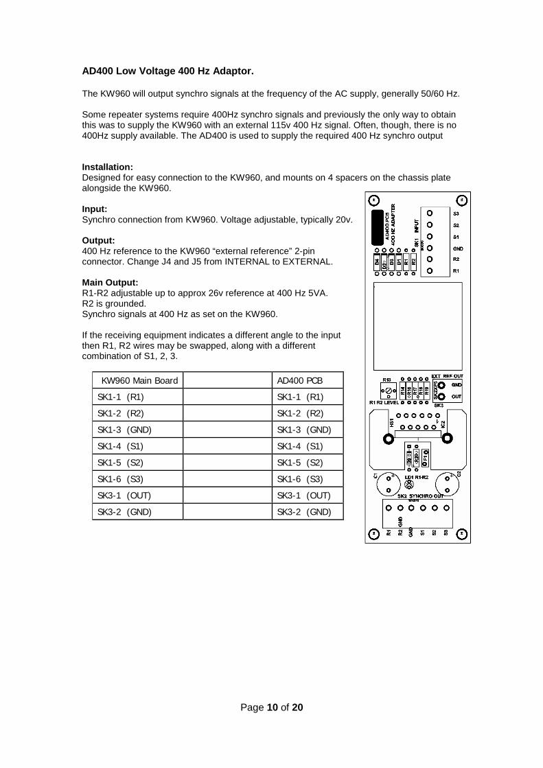
AD400 Low Voltage 400 Hz Adaptor. The KW960 will output synchro signals at the frequency of the AC supply, generally 50/60 Hz. Some repeater systems require 400Hz synchro signals and previously the only way to obtain this was to supply the KW960 with an external 115v 400 Hz signal. Often, though, there is no 400Hz supply available. The AD400 is used to supply the required 400 Hz synchro output Installation: Designed for easy connection to the KW960, and mounts on 4 spacers on the chassis plate alongside the KW960. Input: Synchro connection from KW960. Voltage adjustable, typically 20v. Output: 400 Hz reference to the KW960 “external reference” 2-pin connector. Change J4 and J5 from INTERNAL to EXTERNAL. Main Output: R1-R2 adjustable up to approx 26v reference at 400 Hz 5VA. R2 is grounded. Synchro signals at 400 Hz as set on the KW960. If the receiving equipment indicates a different angle to the input then R1, R2 wires may be swapped, along with a different combination of S1, 2, 3.
KW960 Main Board AD400 PCB
SK1-1 (R1) SK1-1 (R1)
SK1-2 (R2) SK1-2 (R2)
SK1-3 (GND) SK1-3 (GND)
SK1-4 (S1) SK1-4 (S1)
SK1-5 (S2) SK1-5 (S2)
SK1-6 (S3) SK1-6 (S3)
SK3-1 (OUT) SK3-1 (OUT)
SK3-2 (GND) SK3-2 (GND)
Page 11 of 20
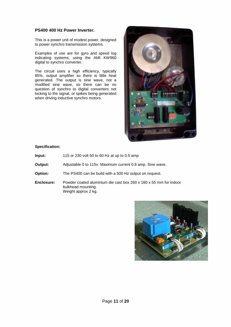
PS400 400 Hz Power Inverter. This is a power unit of modest power, designed to power synchro transmission systems. Examples of use are for gyro and speed log indicating systems, using the AMI KW960 digital to synchro converter. The circuit uses a high efficiency, typically 85%, output amplifier so there is little heat generated. The output is sine wave, not a modified sine wave, so there can be no question of synchro to digital converters not locking to the signal, or spikes being generated when driving inductive synchro motors. Specification: Input: 115 or 230 volt 50 to 60 Hz at up to 0.5 amp Output: Adjustable 0 to 115v. Maximum current 0.8 amp. Sine wave. Option: The PS400 can be build with a 500 Hz output on request. Enclosure: Powder coated aluminium die cast box 260 x 160 x 55 mm for indoor bulkhead mounting. Weight approx 2 kg.

Page 12 of 20
TF960 Step Up Transformer Adaptor.
• Remove the KW960 PCB. • Fit the transformer TF960 in its place. • Use M3 25/30mm spacers to mount the KW960 above the TF960. Wire across from
the Main Board synchro output SK1 to the TF960 SK2. • The TF960 synchro output SK3 will give out about 120 volts reference off load.

Page 13 of 20
TF960 using External 115V 400Hz as the main AC supply. Remove TF1 and solder two wire links in place of as shown below.
Connect as follows: 115V 400Hz supply direct to SK6 - AC INPUT.
Output is on SK3 on the TF960 PCB. Note! TF960C adaptors do not have the TF2 available.
KW960 Main Board TF960
SK1-1 (R1) Not connected SK2-1 (R1)
SK1-2 (R2) Not connected SK2-2 (R2)
SK1-3 (GND) SK2-3 (GND)
SK1-4 (S1) SK2-4 (S1)
SK1-5 (S2) SK2-5 (S2)
SK1-6 (S3) SK2-6 (S3)

Page 14 of 20
Data out LED LD3, Data test point J1: LD3 flashes 1 per second in time with the data output. Regular flashing means that the microprocessor circuit is running correctly. Use J1 to monitor the microprocessor operation. A proprietary NMEA 0183 sentence contains in the first field the angle the KW960 is outputting. STATUS LED LD4:
1. OFF = no power 2. STEADY RED = microprocessor not running correctly 3. FLASH RED/GREEN = Processor OK. Data input is NOT CORRECT FORMAT 4. GREEN = Processor OK. Data input is valid and being used
Rotation Speed SW1: Adjust this hex switch for an output rotation speed. 0 is the slowest at about 2 degrees per second and 9 the fastest at about 10 degrees per second. The exception is the 1:1 mode where rotation is fixed at about 60 degrees per second. The KW960 can not lose synchronisation with the input. If the output turns too rapidly some repeaters may not keep up, and in any ratio other than 1:1 could slip out of synchronisation. Adjusting for Correct Phase Connections:
ALWAYS SWITCH OFF BEFORE DISCONNECTING ANY SYNCHRO WIRE. Disconnection can cause a high voltage spike which might damage the output drivers.
• AT SWITCH-ON in the 1:1 RATIO MODE. This is ideal for setting up the voltage • S1-S2 = 0 volts • S2-S3 = S3-S1 = 0.86 of max phase to phase voltage. • The output waveform is not a pure sine wave. • The S1, S2, S3, frequency is either:
a. the frequency of the main supply (J4 and J5 = INT) or b. the frequency of an external reference.
On first testing you may find the repeater turns in the wrong direction, and/or is many degrees out of alignment. Change R1-R2 and S1, S2, S3 wires logically until the repeater indicates and turns correctly. There are 12 possible combinations. Write them down and eventually you should find the correct combination. If you do not, then the repeater itself needs alignment. The natural synchro zero position with one phase measurement = 0v is always assumed to be zero degree, see the graph on the data sheet.

Page 15 of 20
Testing the KW960: If you have any doubt the first thing to do is to read the data output at J1. It will tell you the settings and show the system is alive and reading the data you input. The data is an NMEA 0183 proprietary sentence, with the angle as the first data field. Testing the synchro output:
• Disconnect the load, and make sure the jumpers are set for 1:1 option. • (On a different ratio you must make due allowance. A 360:1 ratio means a 1 degree
input change will rotate the synchro 1 revolution back to the same position!) • Switch on and measure the synchro output voltages. Adjust R16 to the voltage as
required. • The absolute voltage does not matter, but the ratios do. • To prove each amplifier observe LD5 LD6 LD7, the output LEDS.
Also measure volts from ground (E) to S1, S2 and S3. Each should be active. • Refer to the graph and the following tables. At 60 degree intervals one LED will go out. Angle S1-GND S2-GND S3-GND LD5 LD6 LD7 030 1 0 1 090 1 1 0 150 0 1 1 210 1 0 1 270 1 1 0 330 0 1 1 Table of angle on 1:1 ratio and voltage on scale of 10 volts. ANGLE S1-GND S2-GND S3-GND ANGLE 0 to 10v 0 to 10v 0 to 10v 000 4.8 4.8 10.0 180 010 6.2 3.1 9.8 190 020 7.5 1.5 9.3 200 030 8.5 0.0 8.5 210 040 9.3 1.5 7.5 220 050 9.8 3.1 6.2 230 060 10.0 4.8 4.8 240 070 9.8 6.2 3.1 250 080 9.3 7.5 1.5 260 090 8.5 8.5 0.0 270 100 7.5 9.3 1.5 280 110 6.2 9.8 3.1 290 120 4.8 10.0 4.8 300 130 3.1 9.8 6.2 310 140 1.5 9.3 7.5 320 150 0.0 8.5 8.5 330 160 1.5 7.5 9.3 340 170 3.1 6.2 9.8 350
Testing with the Load directly connected (no transformer adaptor fitted): • Switch off, connect the load, switch on • Output voltages should remain much the same. Adjust R16 slightly if necessary • Check that the heat sinks do not get very hot. • Synchro repeaters can act as a transformer and feed voltage INTO the KW960,
which it will try to sink, resulting in increased dissipation, which is not wanted. • Rotate the input again, you already KNOW the output rotates correctly. • The synchro repeater should turn.

Page 16 of 20
Testing with a Transformer Adaptor: • Measure the voltages at the adapter input, and output, and you will see them
double, OFF LOAD. • The transformer has internal resistance so the output voltage must drop when on
load, just like a signal generator which has its internal source impedance. You will therefore have to turn the voltage output higher using R16.
• Connect the load and measure the output. • The voltages output may be reduced if the receiver takes power or increased if
the receiver is feeding voltage back into the transformer adapter. • Rotate the input. The synchro repeater should turn in synchronisation.
Notes on driving a Control Transformer: CT loads are highly inductive and it is an advantage to tune it by connecting three capacitors across the phases, for they then need less power to drive. I do know an easy method of calculating the capacitors, but values of about 0.1 to 1 microfarad are expected at 60 Hz. The voltage will rise at resonance. Control transformers may be used in a servo loop system, where a feedback circuit searches for a null. Often there is a coarse (1:1) and a fine CT of maybe 36:1. The fine control transformer produces a much more accurate null than the 1:1. Dual KW960’s have been supplied for this application. CT systems will probably work well without the transformer adapter; indeed maybe they will work better for the low impedance source of the KW960 would be applied directly to the high impedance load. Testing the Sine/Cosine output: Connect as follows: Ground = Common S1 = Sine S2 = Cosine S3 = Ref
• Do not connect to the repeater yet. • Input heading at various values & Measure the S1 and S2 voltages • Measure the voltages at the adapter input, and output. • Sine 000.0 deg = 0 v. Sine 090.0 deg = max volts. • Cosine 000.0 deg = max volts. Cosine 090.0 deg = 0v. • Sine and Cosine 045.0 deg = 0.7 of max value volts.
Ventilation: The amplifiers will run warm. It is a good idea to leave off the gland plate to allow the circulation of air. This is commonly left off to ease the passing of cables. Another idea is to remove the gasket material at the top and bottom of the door. Do not install the KW960 in a very hot compartment.

Page 17 of 20
Board Layout.

Page 18 of 20
This page intentionally blank
Page 19 of 20
AMI Marine (UK) Warranty; (abbreviated, full version on request) The Warranty Period is 12 months return to base, parts and labour from date of purchase unless an alternative period has been otherwise agreed in writing. This warranty shall only apply where the REGISTRATION CARD supplied with the goods has been properly completed and returned to AMI Marine (UK) within the period of 21 days from installation. The registration form can also be downloaded from the AMI Marine (UK) website www.amimarine.net Returns Procedure; Send an email RE: REQUEST FOR RETURN AUTHORISATION to [email protected] Please do NOT send items back to AMI Marine (UK) until after you have received a Return Authorisation Response Email instructing you to do so. Documents to be included; A copy of the original INSTALLATION REPORT and a print out of your RETURN MATERIAL AUTHORISATION INFORMATION EMAIL, and enclose both in the return package. Be sure to pack the returning product securely and according to carrier instructions. Damage incurred during return shipping due to inadequate protection will render the item ineligible for return, repair, or exchange under the Warranty Terms. Items not received by AMI Marine, will not be credited. MOST authorised returns should be returned to the address below - however there are some exceptions, so DO NOT ship to this address without first reviewing your RETURN AUTHORISATION INFORMATION EMAIL for applicable return instructions: AMI Marine (UK) Ltd Unit 9, Crosshouse Centre Crosshouse Road Southampton SO14 5GZ United Kingdom A full explanation of AMI Marine (UK) Ltd warranty conditions can be found on our web site or requested via email. * Terms of Service and Policies are subject to change without notice.
------------------------------------------------------------------------------------------------------------------------------------------------------------------------------------------
Please complete and return to AMI Marine (UK) either by post to the above address or by email to [email protected]
Warranty Registration Form
Model Number
Serial Number
Date of Purchase
Installation Company
Vessel Name
IMO Number

Page 20 of 20
This page intentionally blank