Kushal Singh 1, a B. Hari Prasad 1, b and Dr. P ... of Computed Tomography and Coordinate Metrology...
6
Integration of Computed Tomography and Coordinate Metrology in Reverse Engineering of Typical Ceramic Radome Kushal Singh 1, a , B. Hari Prasad 1, b and Dr. P. Bhattacharjee 1, c 1 Defence Research and Development Laboratory, Kanchanbagh, Hyderabad, India a [email protected], b [email protected], c [email protected] Keywords: Computed Tomography, Coordinate Metrology, CMM, Reverse Engineering Abstract: Geometrical information of external surface of an object containing freeform surfaces can be accurately measured using CNC Coordinate Measuring Machine (CMM). Limitations of CMM for measurement of inaccessible and internal geometrical details are overcome by Computed Tomography (CT) technique. Computed tomography is a Nondestructive Evaluation (NDE) technique for producing 2-D and 3-D cross-sectional images of an object from flat X-ray images. Characteristics of the internal structure of an object such as dimensions, shape, internal defects, and density are determined from CT images. The paper presents the methods adopted to obtain complete geometrical information through Reverse Engineering (RE) process of a typical ceramic radome which is used in aerospace applications. Radome consists of two parts a ceramic radome and a metallic bulkhead, which are assembled together. External geometrical details are measured using CMM and the coordinate data generated by CMM are imported in CAD design software to develop a 3D CAD model. Computed tomography is used for evaluation of inaccessible and internal geometrical features and to find out joint structure between Radome and Bulkhead. The data of Coordinate Measuring Machine (CMM), Computed Tomography (CT) and Radiography are used together to generate a parametric 3D CAD model using SolidWorks design CAD software. 1. Introduction The radome is a non-metallic part of the typical aerospace vehicle to act as an electromagnetic (EM) "window" for radar or heat-seeking EM devices located inside the aerospace vehicle. Radar (Radio Detection and Ranging) transmits EM pulses that bounce off the target and return to the radar to provide target location, direction and speed. Figure 1: Radome Typically a Radome is foremost section of an aerospace vehicle and the geometry of radome is largely determined by aerospace vehicle aerodynamics [1]. Radome is a thermo-structural member that protects the antenna of the aerospace vehicle. It is subjected to severe thermal as well Ceramic Radome Metallic bulk head More Info at Open Access Database www.ndt.net/?id=15050
-
Upload
nguyentram -
Category
Documents
-
view
214 -
download
0
Transcript of Kushal Singh 1, a B. Hari Prasad 1, b and Dr. P ... of Computed Tomography and Coordinate Metrology...

Integration of Computed Tomography and Coordinate Metrology in Reverse Engineering of Typical Ceramic Radome
Kushal Singh 1, a , B. Hari Prasad 1, b and Dr. P. Bhattacharjee 1, c 1Defence Research and Development Laboratory, Kanchanbagh, Hyderabad, India
a [email protected], b [email protected], c [email protected]
Keywords: Computed Tomography, Coordinate Metrology, CMM, Reverse Engineering
Abstract: Geometrical information of external surface of an object containing freeform surfaces
can be accurately measured using CNC Coordinate Measuring Machine (CMM). Limitations of
CMM for measurement of inaccessible and internal geometrical details are overcome by Computed
Tomography (CT) technique. Computed tomography is a Nondestructive Evaluation (NDE)
technique for producing 2-D and 3-D cross-sectional images of an object from flat X-ray images.
Characteristics of the internal structure of an object such as dimensions, shape, internal defects, and
density are determined from CT images.
The paper presents the methods adopted to obtain complete geometrical information through
Reverse Engineering (RE) process of a typical ceramic radome which is used in aerospace
applications. Radome consists of two parts a ceramic radome and a metallic bulkhead, which are
assembled together. External geometrical details are measured using CMM and the coordinate data
generated by CMM are imported in CAD design software to develop a 3D CAD model.
Computed tomography is used for evaluation of inaccessible and internal geometrical features and
to find out joint structure between Radome and Bulkhead.
The data of Coordinate Measuring Machine (CMM), Computed Tomography (CT) and
Radiography are used together to generate a parametric 3D CAD model using SolidWorks design
CAD software.
1. Introduction
The radome is a non-metallic part of the typical aerospace vehicle to act as
an electromagnetic (EM) "window" for radar or heat-seeking EM devices located inside the
aerospace vehicle. Radar (Radio Detection and Ranging) transmits EM pulses that bounce off the
target and return to the radar to provide target location, direction and speed.
Figure 1: Radome
Typically a Radome is foremost section of an aerospace vehicle and the geometry of radome
is largely determined by aerospace vehicle aerodynamics [1]. Radome is a thermo-structural
member that protects the antenna of the aerospace vehicle. It is subjected to severe thermal as well
Ceramic Radome
Metallic bulk head
Mor
e In
fo a
t Ope
n A
cces
s D
atab
ase
ww
w.n
dt.n
et/?
id=
1505
0

as structural loads during the flight. The ceramic radome is attached to the metallic bulkhead as
shown in Fig. 1. The ceramic radome is typically made of gel cast process and the bulk head is
made of INVAR. The radome assembly is attached to the airframe through studs.
Reverse Engineering techniques are used to evaluate geometry of radome and the details of
Bulkhead and radome joint. Reverse Engineering is a term used to describe the creation of a digital
dataset based on a physical representation, inverting the regular process of going from an idea
through CAD construction to a product [2]. Inclusion of the design intent of product is must in a
reverse engineering process for product development and accordingly reverse engineering methods
are selected.
2. Acquisition of data for the Surface Geometry of Radome using CMM
CMM is used to obtain coordinates of points (Cartesian system - X, Y, Z coordinates) on the
external and internal surface of Radome. Measurement is carried out in four generatrics (0°, 90°,
180° and 270°) of Radome transverse cross-section as shown in Fig. 2. Average values of the
coordinates are taken to minimise the errors of measurement.
Figure 2: Measurement set up for evaluation of radome surface profile on CMM
Radome
Profile
CMM probe
Transverse
Cross section
Longitudinal
Cross section
Sta
tion 2
70⁰
Station180⁰
Sta
tion 9
0⁰
Station 0⁰ + X
+ Y
Radome

3. Acquisition of Internal geometry of radome using NDE methods
Measurement techniques using a tactile CMM or an optical device like a Laser scanner can
only measure the exterior surface of the hardware but not the internal geometry and features.
Computed Tomography (CT) and Radiography are used to assess the internal geometrical details of
the Radome.
The measurement by CT typically results in a large series of 2D grey-value images, where
each image contains all geometrical information of one planar slice through the measured object.
Various slices are taken as shown in Fig. 3 to find out the Bulkhead and Ceramic Radome joint
details. Technical specifications of CT system used for evaluation of internal geometry of radome
are given below.
Figure 3: Computed Tomography set up
Technical Specifications of CT System
a) Mechanical manipulator
Axis : 6
b) Accuracy
Linear : 40 micron
Rotary : 0.01 arc sec
c) X-ray source
Voltage, current : 450kV, 10mA
Focal spot sizes : 1.2, 3.0mm
d) Detector
Type : Scintillator
Channels : 256
Pitch : 1.3mm
Aperture : 0.8mm
Dynamic range : 18 bit
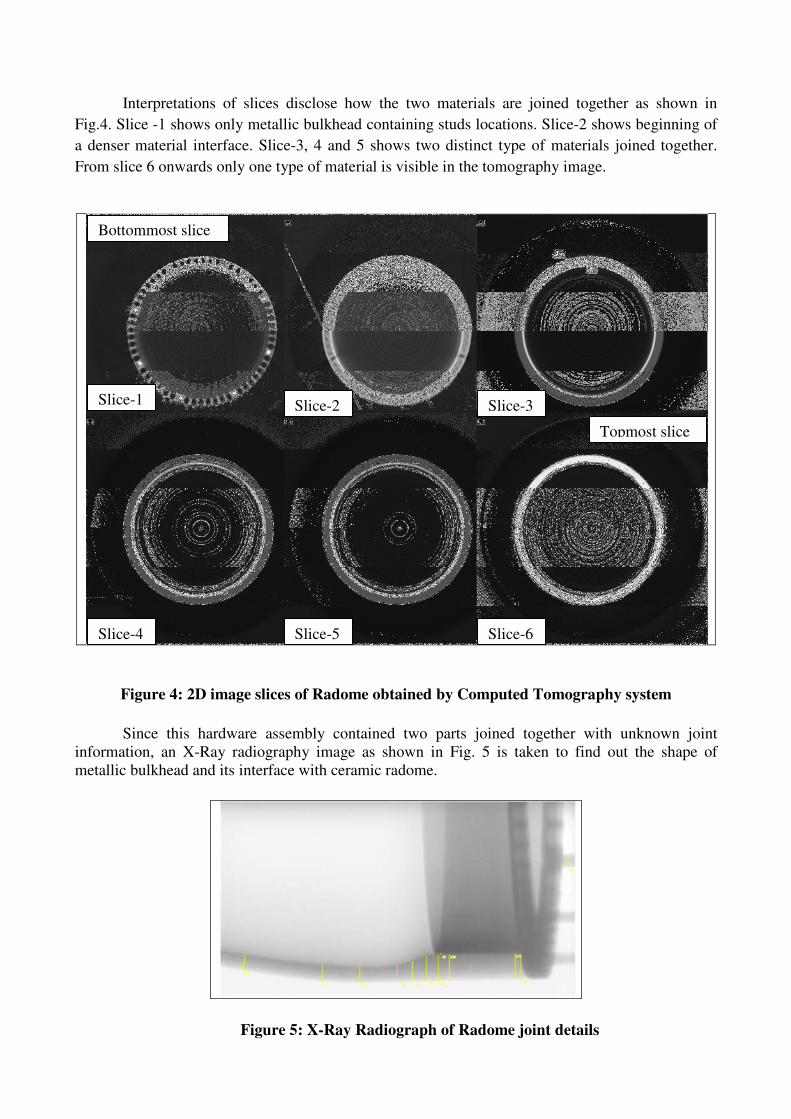
Interpretations of slices disclose how the two materials are joined together as shown in
Fig.4. Slice -1 shows only metallic bulkhead containing studs locations. Slice-2 shows beginning of
a denser material interface. Slice-3, 4 and 5 shows two distinct type of materials joined together.
From slice 6 onwards only one type of material is visible in the tomography image.
Figure 4: 2D image slices of Radome obtained by Computed Tomography system
Since this hardware assembly contained two parts joined together with unknown joint
information, an X-Ray radiography image as shown in Fig. 5 is taken to find out the shape of
metallic bulkhead and its interface with ceramic radome.
Figure 5: X-Ray Radiograph of Radome joint details
Bottommost slice
Topmost slice
Slice-1 Slice-2 Slice-3
Slice-4 Slice-5 Slice-6

4. Reverse Engineering Methodology for CAD data generation
Reference axis system as per CMM measurement and Planes are taken in SolidWoks CAD
modeling software. Coordinates (x, y, and z) of CMM measured points are imported as per
measurement plane. Curves are generated by joining coordinate points. Since the hardware is axis -
symmetric CAD model is generated as a feature of revolution as shown in Fig. 6.
Figure 6: Radome CAD model generated as feature of revolution
The shape and dimensions of the bulkhead as obtained by CT data and Radiography is used
to generate 3D CAD model.
Thus geometrical information about the hardware, captured by Coordinate Measuring
Machine (CMM), Computed Tomography (CT) and Radiography are used together to generate a
parametric 3D CAD model.
Figure 7: CAD model Assembly
The generated CAD model as shown in Fig.7 being an editable version made in a
SolidWorks CAD modeling software can be used to further modify the existing design of the
radome.

5. Future Scope of work : Three-dimensional reconstruction using CT
Because CT scanners offer isotropic or near isotropic, resolution, display of images does not
need to be restricted to the conventional axial images. Instead, it is possible for a software program
to build a volume by "stacking" the individual slices one on top of the other. The program may then
display the volume in an alternative manner. Different methods for reconstruction are Multiplanar
reconstruction (MPR), Surface rendering, Volume rendering, Image segmentation etc. In future with
the improved CT data processing capability complete 3D model would be generated for the
hardware in CT system itself.
6. Conclusions
A methodology is developed to evaluate external geometrical information of the radome
using CNC Coordinate Measuring Machine and internal geometrical details are captured by NDE
techniques i.e. Computed Tomography and Radiography.
3D CAD model of radome is generated by using SolidWorks CAD design software with
external and internal geometrical information obtained from CMM, CT and Radiography. The
generated 3D CAD model can be altered for further design modifications and improvements.
Finally we can conclude that integration of CMM, CT and Radiography data along with
design CAD software can be effectively used for Reverse Engineering of hardware.
7. Acknowledgement
The authors express their sincere thanks to Director DRDL for his continuous support and
encouragement to carry out the work. The authors thank all the colleagues of NDE division of
DRDL for providing vital information and carrying out CT and Radiography for the hardware. The
authors would also thank to all the colleagues of Advanced Metrology Division of DRDL who
helped in CMM scanning, data processing, and metrology related activities.
References
[1] Wei-Jiang Zhao, Le-Wei Li, Fellow and Yeow-Beng Gan; Efficient Analysis of Antenna
Radiation in the Presence of Airborne Dielectric Radomes of Arbitrary Shape; IEEE
Transactions on Antennas and Propagation, VOL. 53, NO. 1, JANUARY 2005
[2] Flisch et al, EMPA Switzerland; Industrial Computed Tomography in Reverse Engineering
Applications; International Symposium on Computerized Tomography for Industrial
Applications and Image Processing in Radiology March, 15 - 17, 1999 Berlin, Germany
Proceedings BB 67-CD published by DGZfP.