KUBOTA ENGINE AMERICA Service Training Kubota Engine Training: WG1605, spark ignited.

Kubota
B2910, B7800 BoxerParts List & Mounting Instructions
Jodale • Perry
Printed: 2004/12

Standard Parts List
Qty Description Photo
L&R Rear Brackets
L&R Front Brackets
2 Front Bracket Spacers (No-Loader)
1 Underseat Shield (Upholstered)
1 Valve Control Cover Shield
1 SMV Bracket
2 Cab Lift Brackets (1” Tube)
2 3/8” Black Snap Caps
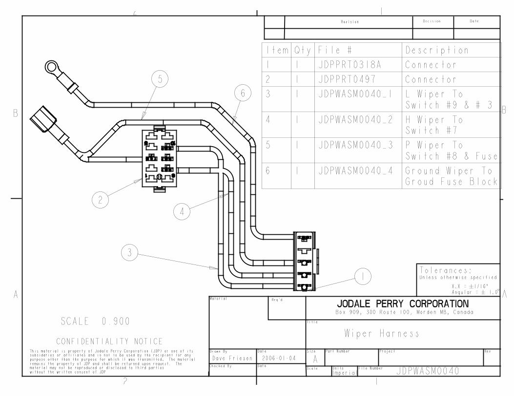
1 Flasher Light Power Extension Harness and Grounding Harness
14 LF 180° O-rubber
11.5 LF 90° O-rubber
L&R Shield Extension Floormat Pieces
1 Centre Platform Floormat
4 Cap, Snap, #245-049
NOTE: All references to left and right are taken from the operator’s point of view when he/she issitting in the driver’s seat.
Kubota B2910 Mounting Instructions

Standard Bolts List
Qty Description
4 Isolator, Rubber, 9/16” x 2 ½”, Black
2 Washer, Flat, Rubber, 9/16” x 2 ½”, Black
2 Washer, Flat, Steel, 9/16” x 2 ½”, Yellow Dichrome
2 Washer, Flat, Rubber, 9/16” x 2 ½”, Black, Trimmed One Side
2 Washer, Flat, Steel, 9/16” x 2 ½”, Yellow Dichrome, Trimmed One Side
4 Nut, Hex, ½”, Gr. 8, Yellow Dichrome
4 Bolt, Hex, ½” x 3”, Gr. 8, Yellow Dichrome
4 Washer, Lock, ½”
6 Bolt, Hex, M12x1.75x60MM, Gr. 10.9, Yellow Dichrome
2 Bolt, Flange, 3/8” x ¾”, Yellow Dichrome
Electrical Connectors List
Qty Description
2 Connectors, Loop, 10GA, ¼”
1 Connectors, Loop, 10GA, ½”
1 Connectors, Loop, 10GA, 3/8”
1 Splicer, Wire, Blue
NOTE: All references to left and right are taken from the operator’s point of view when he/she issitting in the driver’s seat.
Kubota B2910 Mounting Instructions
Optional Parts ListsHeater Option (if equipped)
Qty Description Photo
1 Fitting, 3/8NPT - 3/8” Barb, 90d
1 Fitting, 3/8NPT - 3/8” Barb, 180d
1 Splicer, Rad-Hose, 1 1/8”
2 Clamp, Hose, HS-6
2 Clamp, Hose, HS-20
NOTE: All references to left and right are taken from the operator’s point of view when he/she issitting in the driver’s seat.
Kubota B2910 Mounting Instructions

NOTE: Use the following torquespecifications for all hardware: ½”hardware 73 ft-lbs, 3/8” hardware 42ft-lbs, 5/8” hardware 177 ft-lbs.
1. Remove the upper 2-Post ROPS guard (save fasteners to re-use later), rearflasher lights, grab handles, seat & seattrack assembly. If tractor is equippedwith front end loader, de-tach quik-tachloader and then unbolt hyrdaulic valvemounting plate from loader mast support column. If tractor is equipped with fronthydraulics, then unbolt the hydraulicvalve mounting plate. Remove thetoolbox, and SMV sign and bracket.
2. Take the left rear mounting bracketand slide it over the lower 2-Post ROPSmount socket in the fender. The bracketcan only fit one way, and then take thefactory hardware and loosely fasten the
bracket into place. See Figure 1.
3. Repeat for the right rear mountingbracket. See Figure 2.
4. Take the left front mounting bracket. If there is no loader, you will require the
no-loader spacer (if there is a midmower, you will not need the spacer). Carefully slide the bracket into placeunderneath the steering control rod. Take the provided M12x1.75x60 hexbolts and ½” lock washers, and looselyattached the bracket to the bell housing. If the tractor is equipped with loader,then it will be neseccary to remove thethree bolts prior to installation. SeeFigure 3.
NOTE: All references to left and right are taken from the operator’s point of view when he/she issitting in the driver’s seat.
Kubota B2910 Mounting Instructions
Figure 1
Figure 2
Figure 3

5. Repeat for the right front bracket. See Figure 4.
6. Take the underseat shield. Position it around the seat track mount area andaround the controls. Ensure that theshield will not interfere with theoperation of any of the controls. Slit thecentre area to provide access to the seattrack mounting bolts. Bolt into placeunder the seat track. See Figure 5. Re-install the seat. Glue the upholsteryonto the back fender crossmember
behind the seat area. Remove thediptsick and hydraulic speed controlknob. Slide the upholstery past thecontrol lever and ensure there is accessfor the dipstick. Glue the upholstery into place. Re-install the toolbox and the seat when you are done.
7. Now you are ready to install the cabO-rubber. Remove the left door, rightescape window and lower right sidewindow. Also, remover the two rearplastic panels for access to mounthardware. Take the two cab lift brackets and bolt bracket onto the upper A-Ccrossmember through the hole providedright beside the B-post. Attach a chainor lifting strap to the lift brackets andprepare to hoist cab off of shippingpallet. Unbolt the shipping bracket andlift cab off of pallet.
8. Install the cab weatherstripping asshown in the following figures, 6-9.
9. Take the SMV sign bracket and bolt it onto the mount block located underneath the lower C-C crossmember with theprovided 3/8” x ¾” flange bolts.
NOTE: All references to left and right are taken from the operator’s point of view when he/she issitting in the driver’s seat.
Kubota B2910 Mounting Instructions
Figure 4
Figure 5
Figure 6
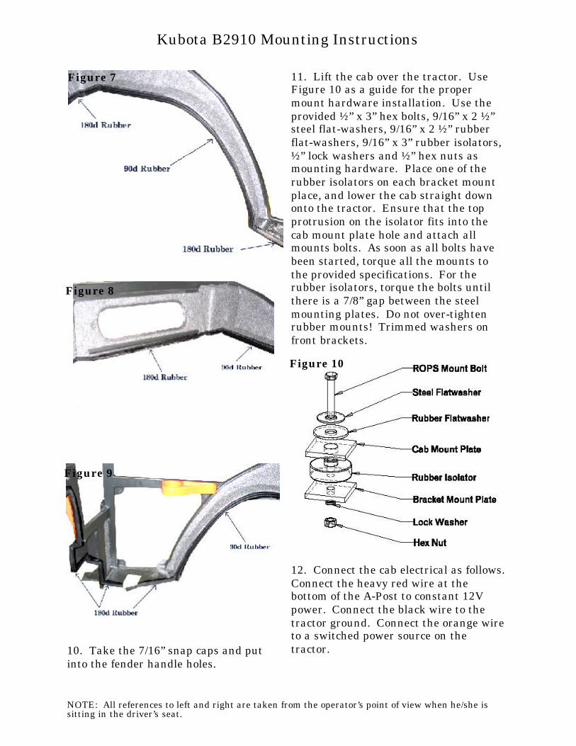
10. Take the 7/16” snap caps and putinto the fender handle holes.
11. Lift the cab over the tractor. UseFigure 10 as a guide for the propermount hardware installation. Use theprovided ½” x 3” hex bolts, 9/16” x 2 ½”steel flat-washers, 9/16” x 2 ½” rubberflat-washers, 9/16” x 3” rubber isolators,½” lock washers and ½” hex nuts asmounting hardware. Place one of therubber isolators on each bracket mountplace, and lower the cab straight downonto the tractor. Ensure that the topprotrusion on the isolator fits into thecab mount plate hole and attach allmounts bolts. As soon as all bolts havebeen started, torque all the mounts tothe provided specifications. For therubber isolators, torque the bolts untilthere is a 7/8” gap between the steel mounting plates. Do not over-tightenrubber mounts! Trimmed washers onfront brackets.
12. Connect the cab electrical as follows. Connect the heavy red wire at thebottom of the A-Post to constant 12Vpower. Connect the black wire to thetractor ground. Connect the orange wireto a switched power source on thetractor.
NOTE: All references to left and right are taken from the operator’s point of view when he/she issitting in the driver’s seat.
Kubota B2910 Mounting Instructions
Figure 10
Figure 7
Figure 8
Figure 9

13. If the tractor has front hydraulics,take the valve control cover shield andinstall 180d O-rubber around the cut-out inside of the panel. Install 90d O-rubber around the outside of the shield, with the bulb facing the inside of the radius, seeFigure 12. Remove the safety stop coverplate on the hydraulic plate as well andinstall 90d O-rubber onto the edge of theplate as shown in Figure 13. Take theshield and slide it onto the valve andthen reinstall the valve mounting plateonto the loader at the loader subframe,and then install the safety stop mountcover plate onto the hydraulic valve, andthen the shield onto the cab frame withthe same fasteners that the lower frontright window uses. The fit is VERY tight and may take a little way to get all thecomponents fit properly. See Figure 14.
14. To provide better access, unbolt therear tractor tailights before proceeding. Take the two sets of tractor flasher lightharnesses and the 3/8” x ¾” flange bolts,and 3/8” flange nuts. Attach the groundharness loop on the chassis hole wherethe light used to be mounted and
attached with the hardware mentionedabove for the left light. Take the largeround light and insert the light throughthe hole in the left side panel, then takethe other end of the harness and bolt theloop to the light bolt. Take the powerharness extension and connect both ends of the harness to the light and the bulletconnector. Repeat for the right rearlight. See Figures 15 and 16.
NOTE: All references to left and right are taken from the operator’s point of view when he/she issitting in the driver’s seat.
Kubota B2910 Mounting Instructions
Figure 14
Figure 13
Figure 12
Figure 15

15. Take the smaller triangular lightand insert through the hole provided inthe left rear plastic panel. Route thewiring through the rubber boot wherethe rear bracket is located and reconnectthe harness. Repeat for the right rearlight. Verify that the lights are workingproperly, and then reinstall the rearpanels onto the cab.
Proceed with the steps 16-18 only if thecab is equipped with the heater option.
16. Drain the antifreeze from the tractor before proceeding. Locate the plug onthe thermostat housing, and unscrew. Take the 3/8NPT-3/8” barb 180d fittingand screw into place (pressure side),REMEMBER to use a silicone sealant onthe threads of the fitting! See Figure 17. Locate the the lower radiator hoselocated beside the filter. Cut out a shortsection and install the hose splicer asshown in Figure 18 with the providedHS-20 hose clamps. Install the 3/8NPT x 3/8” barb 90d fitting (suction) into the
splicer. REMEMBER to use a siliconesealant on the threads of the fitting!
17. Locate the heater hose coming out ofthe cab frame at the bottom of theA-post. Route the hoses into the enginecompartment, being careful that they donot interfere with any moving parts, tiedown as necessary. Using the labels onthe hose, route hose to pressure andsuction sides, ensure that there isadequate hose to each fitting, and thencut the hose. Attach the hoses to thefittings using the HS-6 hose clamps
NOTE: All references to left and right are taken from the operator’s point of view when he/she issitting in the driver’s seat.
Kubota B2910 Mounting Instructions
Figure 17
Figure 18
Figure 16

provided. Ensure ALL connections aretight, and then refill engine antifreeze.
18. Make sure there are no leaks, thenstart the engine, open cab heater valve,and turn on fan, and run at PTO RPM to build up engine heat, engine coolantmust become hot to produce hot air. Keep the radiator cap off to purge thesystem of trapped air, and continue to fill antifreeze as required. Continue to runthe engine and add antifreeze untilheater produces HOT AIR!
19. Take the three floormat pieces. Position the left cab frame piece over theshield extension and glue into place. Position the right part over the shieldextension on the right side and glue intoplace. Take the large centre floormatand place over floormat on platform. Ensure that all pedal controls haveadequate clearance, and then glue intoplace. See Figure 19.
20. To ensure maximum protectionagainst moisture penetration, use ablack urethane sealant on all cracks andsmall openings between floormats andfront shields.
21. Take the SMV sign bracket on theback of the sign and bolt it to the bracket mounted onto the cab frame earlier withthe factory hardware. See Figure 20.
NOTE: All references to left and right are taken from the operator’s point of view when he/she issitting in the driver’s seat.
Kubota B2910 Mounting Instructions
Figure 20
Figure 19