KTM 512 - Microsoft · DN 15-50: 10 mm DN 65-125: 20 mm Actuators: ... IMI TA / Control valves /...
12
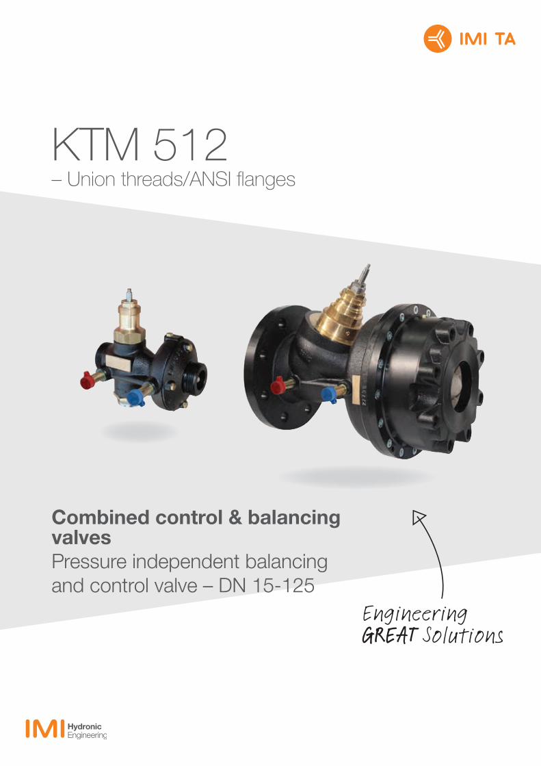
KTM 512 – Union threads/ANSI flanges Combined control & balancing valves Pressure independent balancing and control valve – DN 15-125
Transcript of KTM 512 - Microsoft · DN 15-50: 10 mm DN 65-125: 20 mm Actuators: ... IMI TA / Control valves /...
KTM 512 – Union threads/ANSI flanges
Combined control & balancing valvesPressure independent balancing and control valve – DN 15-125

IMI TA / Control valves / KTM 512 – Union threads/ANSI flanges
2
KTM 512 – Union threads/ANSI flanges
High-performing and compact, these pressure-independent control valves for variable flow heating and cooling systems are particularly effective in situations requiring high temperatures and/or pressure drops. They are also suitable for use on the secondary side in district heating and comfort cooling systems. Rust protection is assured due to the electrophoretically painted ductile iron body, while the plug delivers valve characteristic, suitable for modulating control.
Key features
> Inline designInline flow allows high pressure drops without noise.
> Adjustable flowEnsures the design flow.
> AdaptersFor use with most available actuators.
Technical description
Application:Heating and cooling systems.
Functions: Differential pressure control over the built-in control valve and flow control.
Dimensions:DN 15-125
Pressure class:DN 15-50: PN 25DN 65-125: Class 150
Differential pressure (ΔpV):Max. differential pressure: 1600 kPa = 16 bar (ΔHmax)Min. differential pressure:Low flow (LF): 24 kPa (ΔHmin)Normal flow (NF): 40 kPa (ΔHmin)High flow (HF): 80 kPa (ΔHmin)(Valid for max. position, fully open. Other positions will require lower differential pressure, check with the software HySelect.)
Temperature:Max. working temperature:- with measuring points: 120°C - without measuring points: 150°CMin. working temperature: -10°C
Media:Water or neutral fluids, water-glycol mixtures.
Material:Valve body: Ductile iron EN-GJS-400Diaphragms and gaskets: EPDMValve plug: EPDM/Stainless steel
Surface treatment:Electrophoretic painting.
Marking:IMI TA, DN, PN, Kvs, material and flow direction arrow.
Connection:DN 15-50: Male threads according to ISO 228. (Separate connections with ANSI flanges and UNC threads.)DN 65-125: Flanges according to ASME/ANSI B16.42 Class 150.
Max. lift of the control valve:DN 15-50: 10 mmDN 65-125: 20 mm
Actuators:DN 15-50: TA-Slider 500DN 65-125: TA-Slider 750DN 80-125 HF: TA-Slider 1250For more details on actuators, see separate technical leaflets.KTM 512 can be equipped with adapters for the most common actuators - see “Adapters for actuators”. The max. lift of the actuator must be checked. In the case of a shorter lift the maximum achieved flow will be decreased. Consult your local sales office for details.

3
Operating function
DN 15-50The throttle (2) for flow adjustment, the control valve (9) and the diaphragm operated inline the differential pressure controller (6) are built in series in a common valve body. Pressure upstream of the throttle acts through an internal impulse pipe (V+) to the inlet side of the diaphragm (8). Pressure downstream the control valve acts to the outlet side of the diaphragm together with a spring force. The differential pressure controller pressure relieves the control valve, and at the same time limits the flow to the preset value. As the control valve is pressure relieved, it is possible to use low force actuators.
1. Fixing nut2. Throttle3. Holes for plombing (throttle)4. Holes for plombing (valve body)5. Venting screws6. Inline differential pressure controller7. Valve body8. Diaphragm9. Control valve
DN 65-125The control valve (8) and the diaphragm operated inline differential pressure controller (4) are built in series in a common valve body. Pressure upstream of the control valve acts through an internal impulse pipe (V+) to the inlet side of the diaphragm (2). Pressure downstream of the control valve acts to the outlet side of the diaphragm together with a spring force. The differential pressure controller pressure relieves the control valve, and at the same time limits the flow to the preset value. As the control valve is equipped with lift limitation device, stepless adjustment of maximum flow is possible. As the control valve is pressure relieved, it is possible to use low force actuators.
1. Venting screws2. Diaphragm3. Spring4. Inline differential pressure controller5. Valve body6. Flow adjustment screw7. Fixing nut8. Control valve
V+ 1 2 3 4 5 6
789
11 2 V+ 3 4
8 6 7
5

IMI TA / Control valves / KTM 512 – Union threads/ANSI flanges
4
Sizing
The valve is capable of achieving a maximum flow according to the product tables.Min. differential pressure:Low flow (LF): 24 kPa (ΔHmin)Normal flow (NF): 40 kPa (ΔHmin)High flow (HF): 80 kPa (ΔHmin)
(Valid for max. position, fully open. Other positions will require lower differential pressure, check with the software HySelect.)
Installation
Install the valve in the return pipe, downstream the consumer, or in the inlet pipe, upstream the consumer. Flow direction is shown by the arrow on the valve body. Install the valve so that venting is possible and the flow adjustment scale is visible. Check allowed positions of the actuator. Installation of a strainer upstream of the valve is recommended.When filling, vent the body by using the venting screws.
Normal pipe fittingsTry to avoid mounting taps and pumps immediately before the valve.Installation recommendation for accurate measurement due to distortion of fully developed turbulent flow profile.
Application example
KTM 512

5
Setting
DN 15-50Release the fixing nut (1). Turn the flow setting screw (2) clockwise to the position of 0,0 turns. Turn the flow setting screw anticlockwise corresponding to the number of turns on the flow chart. Tighten the fixing nut. The flow setting can be sealed by using the holes (3a and 3b) on the flow setting screw and the valve body.
DN 65-125Release the fixing nut (7). Turn the flow setting screw (6) clockwise to the position of 0,0 turns. Turn the flow setting screw anticlockwise corresponding to the number of turns on the flow chart. Tighten the fixing nut.
Detailed instructions are delivered with the valves.
Table - Example:Valid table is delivered with each valve.
Measuring accuracy
Kv deviation at different settings (LF/NF/HF)
*) Setting (%) of fully open valve.
67
IMI TA / Control valves / KTM 512 – Union threads/ANSI flanges
6
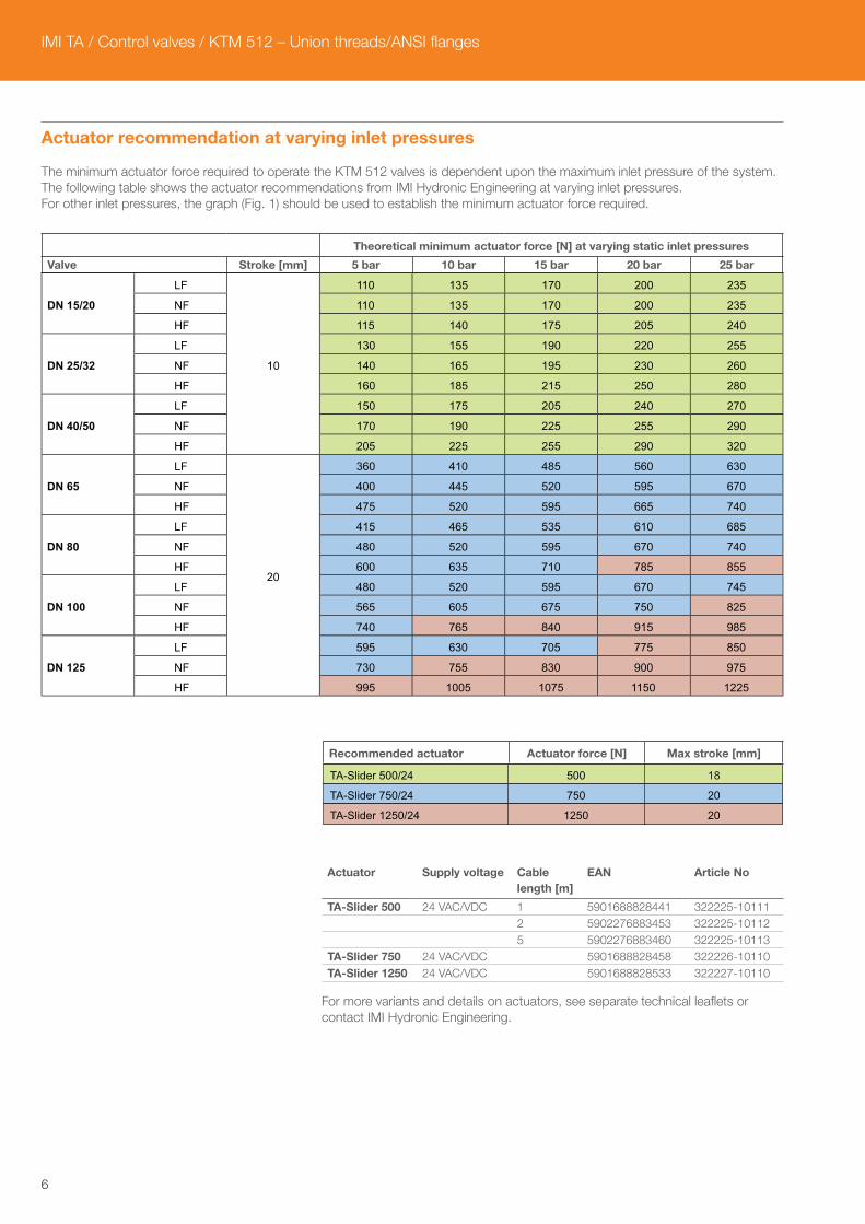
Actuator recommendation at varying inlet pressures
The minimum actuator force required to operate the KTM 512 valves is dependent upon the maximum inlet pressure of the system. The following table shows the actuator recommendations from IMI Hydronic Engineering at varying inlet pressures.For other inlet pressures, the graph (Fig. 1) should be used to establish the minimum actuator force required.
Theoretical minimum actuator force [N] at varying static inlet pressures
Valve Stroke [mm] 5 bar 10 bar 15 bar 20 bar 25 bar
Recommended actuator Actuator force [N] Max stroke [mm]
Actuator Supply voltage Cable length [m]
EAN Article No
TA-Slider 500 24 VAC/VDC 1 5901688828441 322225-10111 2 5902276883453 322225-10112 5 5902276883460 322225-10113TA-Slider 750 24 VAC/VDC 5901688828458 322226-10110TA-Slider 1250 24 VAC/VDC 5901688828533 322227-10110
For more variants and details on actuators, see separate technical leaflets or contact IMI Hydronic Engineering.
DN 15/20
LF
LF
LF
LF
LF
LF
LF
10
110 135 170 200 235
NF
NF
NF
NF
NF
NF
NF
110 135 170 200 235
HF
HF
HF
HF
HF
HF
HF
115 140 175 205 240
DN 25/32
130 155 190 220 255
140 165 195 230 260
160 185 215 250 280
DN 40/50
150 175 205 240 270
170 190 225 255 290
205 225 255 290 320
DN 65
20
360 410 485 560 630
400 445 520 595 670
475 520 595 665 740
DN 80
415 465 535 610 685
480 520 595 670 740
600 635 710 785 855
DN 100
480 520 595 670 745
565 605 675 750 825
740 765 840 915 985
DN 125
595 630 705 775 850
730 755 830 900 975
995 1005 1075 1150 1225
TA-Slider 500/24
TA-Slider 750/24
TA-Slider 1250/24
18500
750
1250
20
20

7
Fig. 1
Force
Inlet pressure
TA-Slider 500
TA-Slider 750
TA-Slider 1250
IMI TA / Control valves / KTM 512 – Union threads/ANSI flanges
8
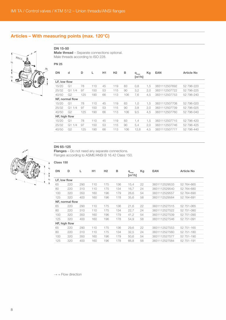
Articles – With measuring points (max. 120°C)
DN 15-50Male thread – Separate connections optional. Male threads according to ISO 228.
PN 25
DN d D L H1 H2 B qmax
[m3/h]Kg EAN Article No
LF, low flow 15/20 G1 78 110 45 119 83 0,8 1,5 3831112507692 52 796-22025/32 G1 1/4 97 150 53 115 90 3,2 2,0 3831112507722 52 796-22540/50 G2 125 190 66 113 106 7,6 4,5 3831112507753 52 796-240NF, normal flow 15/20 G1 78 110 45 119 83 1,0 1,5 3831112507708 52 796-02025/32 G1 1/4 97 150 53 115 90 3,8 2,0 3831112507739 52 796-02540/50 G2 125 190 66 113 106 9,5 4,5 3831112507760 52 796-040HF, high flow 15/20 G1 78 110 45 119 83 1,4 1,5 3831112507715 52 796-42025/32 G1 1/4 97 150 53 115 90 5,4 2,0 3831112507746 52 796-42540/50 G2 125 190 66 113 106 12,6 4,5 3831112507777 52 796-440
DN 65-125Flanges – Do not need any separate connections. Flanges according to ASME/ANSI B 16.42 Class 150.
Class 150
DN D L H1 H2 B qmax
[m3/h]Kg EAN Article No
LF, low flow 65 220 290 110 175 136 15,4 22 3831112529533 52 764-66580 220 310 110 175 134 16,7 24 3831112529540 52 764-680100 320 350 160 196 179 26,6 54 3831112529557 52 764-690125 320 400 160 196 178 35,6 58 3831112529564 52 764-691NF, normal flow 65 220 290 110 175 136 21,6 22 3831112527515 52 751-06580 220 310 110 175 134 22,7 24 3831112527522 52 751-080100 320 350 160 196 179 41,2 54 3831112527539 52 751-090125 320 400 160 196 178 54,9 58 3831112527546 52 751-091HF, high flow 65 220 290 110 175 136 29,6 22 3831112527553 52 751-16580 220 310 110 175 134 32,5 24 3831112527560 52 751-180100 320 350 160 196 179 50,6 54 3831112527577 52 751-190125 320 400 160 196 178 66,8 58 3831112527584 52 751-191
→ = Flow direction
ØD
d
L
H1
H2
B
9
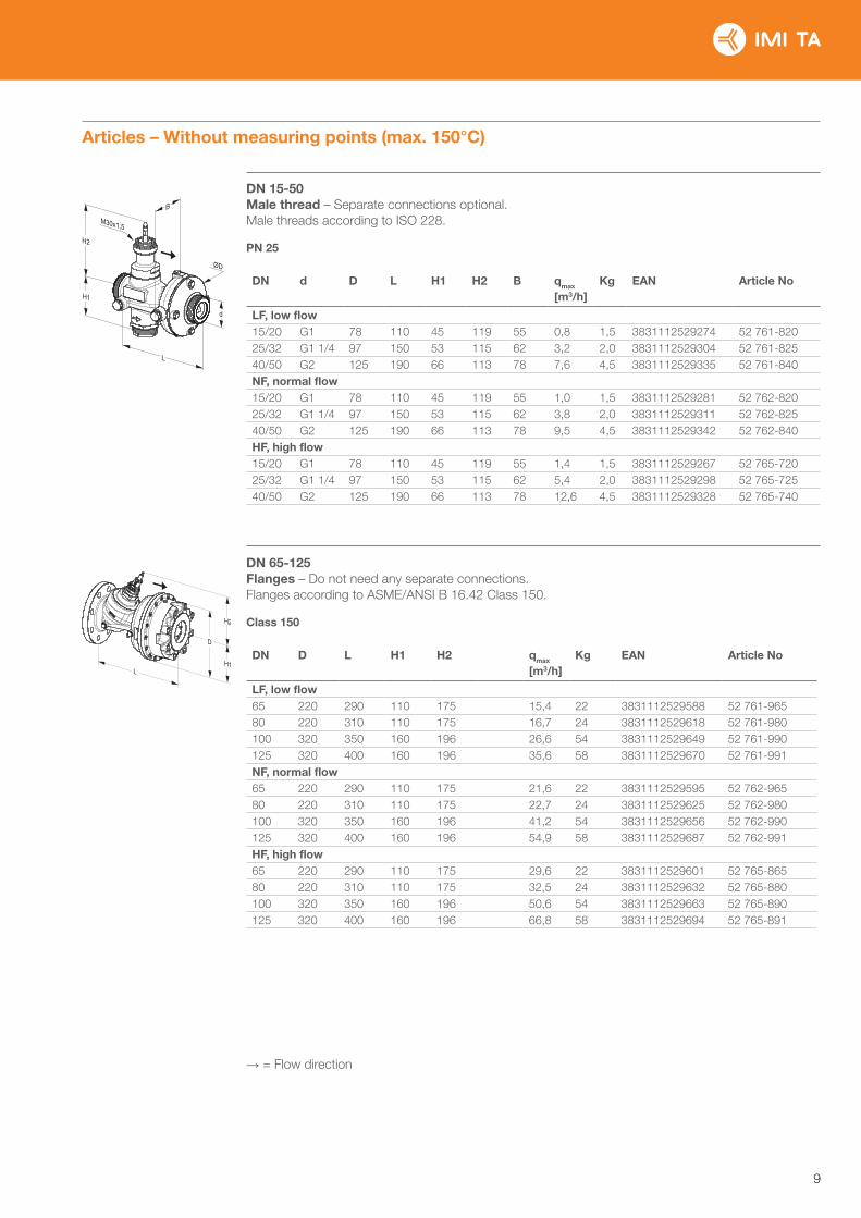
Articles – Without measuring points (max. 150°C)
DN 15-50Male thread – Separate connections optional. Male threads according to ISO 228.
PN 25
DN d D L H1 H2 B qmax
[m3/h]Kg EAN Article No
LF, low flow 15/20 G1 78 110 45 119 55 0,8 1,5 3831112529274 52 761-82025/32 G1 1/4 97 150 53 115 62 3,2 2,0 3831112529304 52 761-82540/50 G2 125 190 66 113 78 7,6 4,5 3831112529335 52 761-840NF, normal flow 15/20 G1 78 110 45 119 55 1,0 1,5 3831112529281 52 762-82025/32 G1 1/4 97 150 53 115 62 3,8 2,0 3831112529311 52 762-82540/50 G2 125 190 66 113 78 9,5 4,5 3831112529342 52 762-840HF, high flow 15/20 G1 78 110 45 119 55 1,4 1,5 3831112529267 52 765-72025/32 G1 1/4 97 150 53 115 62 5,4 2,0 3831112529298 52 765-72540/50 G2 125 190 66 113 78 12,6 4,5 3831112529328 52 765-740
DN 65-125Flanges – Do not need any separate connections. Flanges according to ASME/ANSI B 16.42 Class 150.
Class 150
DN D L H1 H2 qmax
[m3/h]Kg EAN Article No
LF, low flow 65 220 290 110 175 15,4 22 3831112529588 52 761-96580 220 310 110 175 16,7 24 3831112529618 52 761-980100 320 350 160 196 26,6 54 3831112529649 52 761-990125 320 400 160 196 35,6 58 3831112529670 52 761-991NF, normal flow 65 220 290 110 175 21,6 22 3831112529595 52 762-96580 220 310 110 175 22,7 24 3831112529625 52 762-980100 320 350 160 196 41,2 54 3831112529656 52 762-990125 320 400 160 196 54,9 58 3831112529687 52 762-991HF, high flow 65 220 290 110 175 29,6 22 3831112529601 52 765-86580 220 310 110 175 32,5 24 3831112529632 52 765-880100 320 350 160 196 50,6 54 3831112529663 52 765-890125 320 400 160 196 66,8 58 3831112529694 52 765-891
→ = Flow direction
ØD
d
L
H1
H2
B

IMI TA / Control valves / KTM 512 – Union threads/ANSI flanges
10
Adapters for actuators
For DN 15-50
For recommended actuators
For actuator EAN Article No
TA-Slider 750, TA-Slider 1250 3831112512023 52 757-035
For other actuators
For actuator EAN Article No
Belimo NRDVX-3-T-SI 3831112503595 52 757-001Belimo NRDVX-SR-T-CA 3831112512047 52 757-037Belimo UNV 002 3831112511972 52 757-029Belimo UNV 003 3831112512061 52 757-041Clorius V2.05, V4.10 3831112500167 52 757-016Danfoss AMV 10, 13, 20, 23 3831112503465 52 757-008JCI VA-745x 3831112505490 52 757-002JCI VA-715x, VA-720x, VA-774x 3831112512009 52 757-033K&P MD200 3831112512030 52 757-036Honeywell ML 3831112512078 52 757-042HORA MC25 3831112504950 52 757-024HORA MC45 3831112511965 52 757-028Lineg NL 3831112505339 52 757-007Samson 5825 3831112500259 52 757-011Schneider Electric FORTA M400, M800 3831112503007 52 757-019Siemens SQX, SKD, SKB 3831112505360 52 757-022Siemens SAX 3831112531703 52 757-045Sauter AVM 104/114 3831112511989 52 757-030Sauter AVM115SF901 (TA-R25) 3831112511996 52 757-031Sauter AVM115SF901 (TA-R25 plastic) 3831112512054 52 757-038TA-MC55, TA-MC55Y, TA-MC100 3831112512023 52 757-035TA-MC100 FSE/FSR 3831112511538 52 757-026
For DN 65-125
For recommended actuators
For actuator EAN Article No
TA-Slider 750, TA-Slider 1250 3831112512085 52 757-907
For other actuators
For actuator EAN Article No
Belimo UNV 003 3831112512283 52 757-901Belimo NV24 (TA-NV24) 3831112512283 52 757-901Danfoss AMV 55 3831112533905 52 757-924Sauter AVN 224, AVF 234, AVM 234 3831112504486 52 757-904Schneider Electric Forta 3831112512092 52 757-906Siemens SQX, SKD, SAX 3831112510661 52 757-903TA-MC55, TA-MC55Y 3831112509269 52 757-905TA-MC100 3831112512085 52 757-907TA-MC100 FSE/FSR 3831112511781 52 757-912TA-MC160 3831112511910 52 757-913

11
Connections
With female threadThreads according to ISO 228.Swivelling nut
d1 d2 L1* EAN Article No
G1 G1/2 26 3831112501027 52 759-015G1 G3/4 32 3831112501034 52 759-020G1 1/4 G1 47 3831112501041 52 759-025G1 1/4 G1 1/4 52 3831112501058 52 759-032G2 G1 1/2 52 3831112503489 52 759-040G2 G2 64,5 3831112503205 52 759-050
With female thread RcThreads according to ISO 7-1Swivelling nut
d1 d2 L1* EAN Article No
G1 Rc1/2 26 3831112527454 52 751-301G1 Rc3/4 32 3831112527461 52 751-302G1 1/4 Rc1 47 3831112527478 52 751-303G1 1/4 Rc1 1/4 52 3831112527485 52 751-304G2 Rc1 1/2 52 3831112527492 52 751-305G2 Rc2 64,5 3831112527508 52 751-306
With female thread NPTThreads according to ANSI/ASME B1.20.1-1983.Swivelling nut
d1 d2 L1* EAN Article No
G1 1/4 1 NPT 73 3831112533394 52 751-307G1 1/4 1 1/4
NPT80 3831112533400 52 751-308
G2 1 1/2 NPT
82 3831112533417 52 751-309
G2 2 NPT 93 3831112533424 52 751-310
With male threadThreads according to ISO 7Swivelling nut
d1 d2 L1* EAN Article No
G1 R1/2 34 3831112500983 52 759-115G1 R3/4 40 3831112500990 52 759-120G1 1/4 R1 40 3831112501003 52 759-125G1 1/4 R1 1/4 45 3831112501010 52 759-132G2 R1 1/2 45 3831112503342 52 759-140G2 R2 50 3831112503472 52 759-150
For weldingSwivelling nut
d1 D L1* EAN Article No
G1 20,8 37 3831112500945 52 759-315G1 26,3 42 3831112500952 52 759-320G1 1/4 33,2 47 3831112500969 52 759-325G1 1/4 40,9 47 3831112500976 52 759-332G2 48,0 47 3831112501140 52 759-340G2 60,0 52 3831112501294 52 759-350
With ANSI flangeAccording to ASME/ANSI B 16.42 Class 150
d1 d2 D L1* EAN Article No
G1 1/2”-13 UNC 89 10 3831112511811 52 759-815G1 1/2”-13 UNC 98,5 20 3831112511835 52 759-820G1 1/4 1/2”-13 UNC 108 5 3831112511866 52 759-825G1 1/4 1/2”-13 UNC 117,3 15 3831112511873 52 759-832G2 1/2”-13 UNC 127 5 3831112511897 52 759-840G2 5/8”-11 UNC 152,4 20 3831112511491 52 759-850
*) Fitting length (from the gasket surface to the end of the connection).
L1
d2 d1
L1
d2 d1
L1
d2 d1
L1
d2 d1
L1
ØD d1
ØD
L1
d1
d2

IMI TA / Control valves / KTM 512 – Union threads/ANSI flanges
Accessories
Measuring pointAMETAL®/EPDM
L EAN Article No
44 7318792813207 52 179-014103 7318793858108 52 179-015
Measuring point, extension 60 mmCan be installed without draining of the system.AMETAL®/Stainless steel/EPDM
L EAN Article No
60 7318792812804 52 179-006
Venting extensionSuitable when insulation is used.Stainless steel/EPDM/Brass.
d D L EAN Article No
M6 12 70 3831112531727 52 759-220
Venting screwBrass/EPDM
d EAN Article No
M6 3831112527980 52 759-211
The products, texts, photographs, graphics and diagrams in this document may be subject to alteration by IMI Hydronic Engineering without prior notice or reasons being given. For the most up
to date information about our products and specifications, please visit www.imi-hydronic.com.
6-10-25 KTM 512 – Union threads/ANSI flanges ed.3 11.2017
d
ØD
L
d