KTA3 Motor Circuit Controller - Apache2 Ubuntu Default...
15
Motor Circuit Controllers F F84 KTA3 The new KTA3-100 is rated to 90A and has a 2000A group installation rating, one of the highest in the industry. In one small package, Sprecher + Schuh's KTA3 Motor Circuit Con- troller combines the functions of: • Short circuit protection, • Thermal overload protection, • Switching, and • Signaling Ideal for group motor installations… The KTA3 can eliminate the need for larger and more expensive fuse blocks and fused disconnects, or circuit breakers. The potential cost savings in group motor installations can be as much as 35% over conventional methods of branch circuit protection. And, because so many features are combined into one small unit, panel space can be slashed by as much as 60%. In addition, the KTA3 line offers a wide application range from 0.1 to 90 FLA in installations up to 600V. For group motor applications, the KTA3 series has up to a 2000A group installation rating, one of the highest in the industry. Or as a manual starter The KTA3 is also an excellent manual motor starter that employs all of the same motor protection features in one compact unit. The KTA3 is available in a variety of enclosures including general purpose, watertight and explosion proof (the most compact on the market today). Excellent short circuit and thermal overload protection In the event of a short-circuit, the contacts are opened by magnetic, non- adjusting tripping elements in times approaching 1/1000 of a second. This results in the extremely rapid build-up of an arc voltage which limits the cur- rent of the short-circuit to a very low level. Because of this superb current limiting capability, the KTA3 has a KTA3 Motor Circuit Controller Reduces panel space and saves money in group motor applications short-circuit capacity of up to 42kA at 600V. Because each KTA3 is individually calibrated at the factory for the smallest and largest current, very accurate thermal overload protection is also obtained. In addition, the KTA3 is a Class 10 device ... it trips within 10 seconds under a locked rotor condition (6 x FLA). Other protection features Single-phase protection is provided by the KTA3-25 at a maximum of 1.25 x FLA, thus accurate adjustment of the overload trip ensures effective motor protection even with a phase loss. The KTA3-100 provides accelerated trip- ping under single-phase conditions through the use of a differential trip- ping mechanism (see Section A in this catalog for a full explanation of differ- ential tripping). Every KTA3 Motor Circuit Controller is also equipped with automatic ambient temperature compensation, which continually adjusts to surround- ing temperatures. As a result, trip times remain constant. Accessories add versatility Whether in group motor installations or as a manual motor starter, numer- ous accessories are available to enhance the KTA3’s performance. R
Transcript of KTA3 Motor Circuit Controller - Apache2 Ubuntu Default...

Mot
or C
ircui
tCo
ntro
llers
F
F84
KTA3
The new KTA3-100 is rated to 90A and has a2000A group installation rating, one of the
highest in the industry.
In one small package, Sprecher +Schuh's KTA3 Motor Circuit Con-troller combines the functions of:
• Short circuit protection,• Thermal overload protection,• Switching, and• Signaling
Ideal for group motorinstallations…The KTA3 can eliminate the need forlarger and more expensive fuse blocksand fused disconnects, or circuitbreakers. The potential cost savings ingroup motor installations can be asmuch as 35% over conventionalmethods of branch circuit protection.And, because so many features arecombined into one small unit, panelspace can be slashed by as much as60%.
In addition, the KTA3 line offers awide application range from 0.1 to 90FLA in installations up to 600V. Forgroup motor applications, the KTA3series has up to a 2000A groupinstallation rating, one of the highestin the industry.
Or as a manual starterThe KTA3 is also an excellent manualmotor starter that employs all of thesame motor protection features in onecompact unit. The KTA3 is availablein a variety of enclosures includinggeneral purpose, watertight andexplosion proof (the most compact onthe market today).
Excellent short circuit andthermal overload protectionIn the event of a short-circuit, thecontacts are opened by magnetic, non-adjusting tripping elements in timesapproaching 1/1000 of a second. Thisresults in the extremely rapid build-upof an arc voltage which limits the cur-rent of the short-circuit to a very lowlevel. Because of this superb currentlimiting capability, the KTA3 has a
KTA3Motor CircuitController
Reduces panel spaceand saves money ingroup motor applications
short-circuit capacity of up to 42kA at600V.
Because each KTA3 is individuallycalibrated at the factory for thesmallest and largest current, veryaccurate thermal overload protection isalso obtained. In addition, the KTA3is a Class 10 device ... it trips within10 seconds under a locked rotorcondition (6 x FLA).
Other protection featuresSingle-phase protection is provided bythe KTA3-25 at a maximum of 1.25 xFLA, thus accurate adjustment of theoverload trip ensures effective motorprotection even with a phase loss. TheKTA3-100 provides accelerated trip-ping under single-phase conditionsthrough the use of a differential trip-ping mechanism (see Section A in thiscatalog for a full explanation of differ-ential tripping).
Every KTA3 Motor Circuit Controlleris also equipped with automaticambient temperature compensation,which continually adjusts to surround-ing temperatures. As a result, triptimes remain constant.
Accessories add versatilityWhether in group motor installationsor as a manual motor starter, numer-ous accessories are available to enhancethe KTA3’s performance.
R

Motor Circuit
Controllers
F
F85
KTA3
The KTA3 In Group MotorApplicationsNEC article 430-52 states that eachmotor must have a Branch CircuitProtective Device (BCPD) consistingof a fused disconnect, fuse block, orcircuit breaker. A typical circuit isillustrated in Figure 1.
Figure 1Article 430-52 Circuitry
Even though this method is highlyeffective, it has several drawbacks.
• Breakers or fuse blocks for eachmotor circuit are expensive.
• The panel space required to housemany components like this issubstantial.
• Installations of this type are laborintensive and therefore more costly.
The next article of the code (430-53),however , provides several exceptionsto 430-52 that allow you to connect a
group of motors under one BCPD.
These exceptions can be found under:➊
• 430-53(a) – Titled: “For Motors1 HP or Less”
• 430-53(b) – Titled: “If TheSmallest Motor is Protected”
• 430-53(c) – Titled: “In OtherGroup Installations”
For example, Figure 2 illustrates how acircuit would look utilizing provisions(a) or (b) above. What was once threebranch circuits, with three BCPD’s, isnow one branch circuit with oneBCPD.
Figure 2Article 430-53 Circuitry Without KTA3
It appears that the exceptions in 430-53 take care of the expensive draw-backs to having one BCPD for eachmotor. We have eliminated theexpensive fuses (or circuit breakers).We have significantly reduced thepanel space, and we have reduced thelabor it takes to install the circuit.
Unfortunately, this solution raises adifferent set of problems.
• To service one motor, the powermust be disconnected at the BCPD.This, of course, removes power toall of the other motors.
• The user gives up “close” individualprotection against faults that arelower than the BCPD protectionrating.
• NEC 430-52 (a) or (b) limits thegroup to a few small motors.
However, by applying the KTA3under 430-53 (c) (Figure 3), theproblems associated with 430-53 (a)and (b) are overcome.
Figure 3Article 430-53 Circuitry With KTA3
• We have eliminated all but one fuseblock (or circuit breaker).
• We have significantly reduced thesize of the panel.
• We have decreased the wiring andinstallation time.
• We have provided an individualdisconnect for each motor.
• We have assured protection againstlow level faults that the BCPDwould pass.
• We have a product that is labeledfor group installations.
• We can group larger horsepowermotors with smaller ones.
➊ For more information on applying KTA3 under 430-53, contact your Sprecher + Schuh representative.
Using the KTA3 in group motor applications can reduce panel space as much as 60%.

Mot
or C
ircui
tCo
ntro
llers
KTA3
F
Discount Schedule A-1F86
Motor Circuit Controller
Series KTA3
Short Circuit Ratings ➌Manual Motor Starter / Group Ratings
Catalog Short Circuit Short Circuit Rating
Number Rating (kA) w/ KTL3-65-N
480V 600V 480V 600V
KTA3-25-0.16 42 42 ~ ~
KTA3-25-0.25 42 42 ~ ~
KTA3-25-0.4A 42 42 ~ ~
KTA3-25-0.63A 42 42 ~ ~
KTA3-25-1A 42 42 ~ ~
KTA3-25-1.6A 42 42 ~ ~
KTA3-25-2.5A 42 42 ~ ~
KTA3-25-4A 18 18 ~ ~
KTA3-25-6.3A 18 10 42 42
KTA3-25-10A 10 10 42 42
KTA3-25-16A 10 5 14 14
KTA3-25-20A 5 ~ ~ ~
KTA3-25-25A No longer UL Approved
KTA3-100-25A 65 42 ~ ~
KTA3-100-40A 65 42 ~ ~
KTA3-100-63A 42 18 ~ ~
KTA3-100-90A 35 10 ~ ~
➊ Horsepower ratings shown are for reference. The final selection of the manualstarter depends on the actual motor full load amps and service factor.
Example #1:For a motor with a service factor of 1.15 or greater, use the motor nameplate fullload amps and choose the motor starter with the appropriate current range.
Motor F.L.A. 4.2AService Factor x 1.15Effective Current = 6.3A
Select catalog number KTA3-25-6.3
Example #2:For a motor with a service factor less than 1.15, use the motor nameplate full loadamps times 0.9 and choose the motor starter with the appropriate current range.
Motor F.L.A. 4.2AService Factor x 1.0Multiplier x 0.9Effective Current = 3.78A
Select catalog number KTA3-25-4➋ Single phase horsepower ratings are based on wiring the 3 poles of the device in
series.➌ Reference Sprecher+Schuh UL file #E54612
Maximum OrderingHorsepower ➊➋ O/L Relay Magnetic Information ➊
Single Ø ➋ Three Ø Ampere Response115V 230V 200V 230V 460V 575V Range Current Catalog Number Price
~ ~ ~ ~ ~ ~ 0.1 - 0.16 1.8 KTA3-25-0.16A 133
~ ~ ~ ~ ~ ~ 0.16 - 0.25 2.8 KTA3-25-0.25A 133
~ ~ ~ ~ ~ ~ 0.25 - 0.4 4.4 KTA3-25-0.4A 133
~ ~ ~ ~ ~ ~ 0.4 - 0.63 6.9 KTA3-25-0.63A 154
~ ~ ~ ~ 1/3 1/2 0.63 - 1 11 KTA3-25-1A 154
~ ~ ~ ~ 3/4 3/4 1 - 1.6 18 KTA3-25-1.6A 154
1/10 1/6 1/2 1/2 1 1 1/2 1.6 - 2.5 28 KTA3-25-2.5A 154
1/8 1/3 3/4 3/4 2 3 2.5 - 4 44 KTA3-25-4A 154
1/4 1/2 1 1/2 1 1/2 3 5 4 - 6.3 69 KTA3-25-6.3A 154
1/2 1 1/5 2 3 5 7 1/2 6.3 - 10 110 KTA3-25-10A 176
1 2 3 5 10 10 10 - 16 176 KTA3-25-16A 176
1 1/2 3 5 5 10 15 16 - 20 220 KTA3-25-20A 176
KTA3 Base Unit ➊

Motor Circuit
Controllers
KTA3
F
Discount Schedule A-1 F87
Accessories for KTA3-25Accessory Description Wiring Diagram Catalog Number Price
KT3-25-PE1-10 15
KT3-25-PE2-10 15
KT3-25-PE1-01 15
KT3-25-PE2-01 15
KT3-25-PE-L10 15
KT3-25-PA-11 28
KT3-25-PA-20 28
KT3-25-PA-02 28
Auxiliary Contact Block (NO) -mounts internally.
Auxiliary Contact Block (NO) -mounts internally, terminal markingsappropriate when also using “PA”type auxiliary contact.
Auxiliary Contact Block (NC) -mounts internally.
Auxiliary Contact Block (NC) -mounts internally, terminal markingsappropriate when also using “PA”type auxiliary contact.
Auxiliary Contact Block (EarlyMake) mounts internally.
Two pole Auxiliary Contact Block(NO/NC) - for side mounting. If usingCompact Bus Bar System, choose busbar with 54mm spacing.
Two pole Auxiliary Contact Block -(NO/NO) - for side mounting. If usingCompact Bus Bar System, choose busbar with 54mm spacing.
Two pole Auxiliary Contact Block -(NC/NC) - for side mounting. If usingCompact Bus Bar System, choose busbar with 54mm spacing.
14
13
��
34
33��
12
11
��
32
31��
37
38
14
13
22
21
���
14
13
24
23
��
12
11
22
21
���
Accessories
Series KTA3 Motor Circuit Controller
Accessories for KTA3-25 continued on next page ➟

Mot
or C
ircui
tCo
ntro
llers
KTA3
F
Discount Schedule A-1F88
Coil Selection (✱)Coil Code Coil Voltage
28V 28V60Hz/24V50Hz127V 127V60Hz/110V50Hz240V 240-260V60Hz/220-230V50Hz277V 277V60Hz/240V50Hz440V 440-460V60Hz/380-400V50Hz480V 480V60Hz/415V50Hz
Accessories for KTA3-25 (continued from previous page)Accessory Description Wiring Diagram Catalog Number Price
KT3-25-PF-10 28
KT3-25-PF-01 28
KT3-25-UA-✱ 65
KT3-25-AA-✱ 65
KTL3-65-N 67
KT3-25-AS 11
KTA3-25-DSC 11
Trip Indicator (NO) - mountsinternally. Provides indication of ashort circuit or thermal overloadcondition. Will not indicate a KTA3that has been manually tripped.
Trip Indicator (NC) - mountsinternally.
Undervoltage Release Module -mounts on right hand side. PreventsKTA3-25 from operating unlessvoltage is present.
Shunt Release Module - mounts onright hand side. Remotely trips theKTA3-25.
Current Limiter - Increases the short circuit capacity ofselected KTA3 devices to the following values:
480V 600VKTA3-25-6.3A 42kA 42kAKTA3-25-10A 42kA 42kAKTA3-25-16A 42kA 14kAKTA3-25-20A 14kA 10kA
Snaps directly onto the KTA3 or mounts adjacent using theCompact Bus Bar System (when using the Current Limiter, aSupply Block is not needed).
Can be used in Group Motor Installations with high availablefault currents. Fault repulsion contacts close automatically.
Adaptor PlateProvides capability to base mount one KTA3-25
Locking FixturePadlocking attachment for one KTA3-25. Locks in the OFFposition only. Metal construction. Holds one to three padlockswith 6mm hasps.
Undervoltage & Shunt ReleaseOrdering Instructions● Specify Catalog Number● Replace (✱) With Overload Relay Code
Accessories for KTA3-25 continued on next page ➟
54
53
��
52
51
��
U<
Q1
F1D2D1
������
�����
Q1
F1C2C1
������
����
Accessories
Series KTA3 Motor Circuit Controller
Motor Circuit
Controllers
KTA3
F
Discount Schedule A-1 F89
Accessories for KTA3-25 (continued from previous page)Voltage /
Accessory Description Rated Current Catalog Number Price
KT3-25-KA 49KT3-25-KAZ 86
110/120VAC KT3-25-DL-R-110V220/240VAC KT3-25-DL-R-220V110/120VAC KT3-25-DL-G-110V220/240VAC KT3-25-DL-G-220V 28110/120VAC KT3-25-DL-W-110V220/240VAC KT3-25-DL-W-220V110/120VAC KT3-25-DL-Y-110V220/240VAC KT3-25-DL-Y-220V
KT3-25-DS 11
KT3-25-DM 5
12A KCD4 7
20A KT3-NW23 12
Enclosures - For mountingone KTA3 with side mountaccessories. Knockouts for twotype “DL” pilot lights. Includesground and neutral terminals.
General Purpose (IP41)Watertight (IP55)
Enclosure Pilot Light ➊ -Neon lamp with plug connectorand 180mm cable. Degree ofprotection - IP54.
RedRedGreenGreenWhiteWhiteYellowYellow
Enclosure Locking Fixture -For use with KT3-25-KAenclosures. Holds one to threepadlocks with 6mm hasps.
Enclosure Membrane -Replacement membrane forKT3-25-KAZ enclosure.Includes 4 mounting screws(membrane only, does notinclude mounting frame).
Connecting Module ➋ -Provides a solid “wireless”connection between a KTA3Motor Circuit Controller and allCA4 contactors.
Connecting Module -Provides a solid “wireless”connection between a KTA3Motor Circuit Controller and aCA7 contactor.
Connects CA7-9…23
➊ 480V lights available as special order. Contact yourSprecher + Schuh representative.
➋ Designed for CA4-9-01 only. If Normally Open contactrequired, add CA4-P02 two pole auxiliary contact block.
Accessories
Series KTA3 Motor Circuit Controller
Mot
or C
ircui
tCo
ntro
llers
KTA3
F
Discount Schedule A-1F90
Accessory Description Catalog Number Price
KT3-25-DB-45-2 27KT3-25-DB-45-3 31KT3-25-DB-45-4 35KT3-25-DB-45-5 39
KT3-25-DB-54-2 27KT3-25-DB-54-3 31KT3-25-DB-54-4 35KT3-25-DB-54-5 39
KT3-25-A2 28KT3-25-A3 22
KT3-25-DBA 3
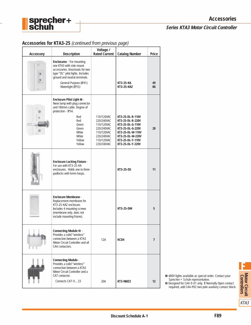
Compact Bus Bar System for KTA3-25
Compact Bus Bar - 45mm spacing - Busbar with 45mm spacing accepts KTA3’s withor without internally mounted auxiliary or tripsignal contact. Rated to 65A (UL)/63A (IEC).
Connects two KTA3-25’sConnects three KTA3-25’sConnects four KTA3-25’sConnects five KTA3-25’s
Compact Bus Bar - 54mm spacing - Busbar with 54mm spacing accepts KTA3’swith side mounted auxiliary contact (typePA-11). Rated to 65A (UL)/63A (IEC).
Connects two KTA3-25’sConnects three KTA3-25’sConnects four KTA3-25’sConnects five KTA3-25’s
Supply Block - Provides connection frombus bar to power. (When using the CurrentLimiter, Supply Blocks are not required.)
Blank Space Cover - Covers bus barconnections where no KTA3-25 is mounted.
KT3-25-A2 KT3-25-A3
Accessories
Series KTA3 Motor Circuit Controller

Motor Circuit
Controllers
KTA3
F
Discount Schedule A-1 F91
KTA3 Explosion Proof Manual Starter - Type “E3” ➊
KTA3 Modifications (Factory Assembled)Description Catalog Number Suffix AdderAuxiliary Contacts
1 NO - Internal -PE1-10 151 NC - Internal -PE1-01 151 NO (Early make) - Internal -PE-L10 151 NO & 1 NC - External -PA-11 ➋ 282 NO - External -PA-20 ➋ 282 NC - External -PA-02 ➋ 28
Trip Indicators1 NO - Internal -PF-10 281 NC - Internal -PF-01 28
Enclosure Padlock Hasp (for EX3 enclosure) -DS 45
➊ “Feed Through” type conduit hubs provided as standard.➋ Modification not available on Type “E3” starter.
Class I, Division 1 & 2, Group C & DClass II, Division 1 & 2, Group E, F & G
Class IIINEMA 7CD & 9EFG
Motor Circuit Controller
Series KTA3
Coil Selection (✱)Coil Code Coil Voltage
28V 28V60Hz/24V50Hz127V 127V60Hz/110V50Hz240V 240-260V60Hz/220-230V50Hz277V 277V60Hz/240V50Hz440V 440-460V60Hz/380-400V50Hz480V 480V60Hz/415V50Hz
Maximum OrderingHorsepower O/L Relay Magnetic Information
Single Ø Three Ø Ampere Response115V 230V 200V 230V 460V 575V Range Current Catalog Number Price
0.1 - 0.16 1.8 KTA3-25-0.16A-E3 3500.16 - 0.25 2.8 KTA3-25-0.25A-E3 3500.25 - 0.4 4.4 KTA3-25-0.4A-E3 350
1/10 1/6 1/2 1/2 1 1 1/2 0.4 - 0.63 6.9 KTA3-25-0.63A-E3 3500.63 - 1 11 KTA3-25-1A-E3 3501 - 1.6 18 KTA3-25-1.6A-E3 350
1.6 - 2.5 28 KTA3-25-2.5A-E3 3502.5 - 4 44 KTA3-25-4A-E3 3504 - 6.3 69 KTA3-25-6.3A-E3 350
2 3 5 7 1/2 15 20 6.3 - 10 110 KTA3-25-10A-E3 35010 - 16 176 KTA3-25-16A-E3 36516 - 20 220 KTA3-25-20A-E3 400
Ordering Instructions● Specify Catalog Number● Replace (✱) With Coil Code where See Coil Code table
where applicable on this page for codes

Mot
or C
ircui
tCo
ntro
llers
KTA3
F
Discount Schedule A-1F92
Technical Information
Series KTA3 Motor Circuit Controller
Technical Information Mounting Position - KTA3-25KTA3-25… KTA3-100…
Standards UL 508; CSA22.2; IEC 947-1/2/4/5; EN 60947
Approvals UL, CSA, CE, SEV, Germ. Lloyd, UL, CSA, CE, Lloyd’s Register ofCEBEC, PTB, DEMKO, SEMKO, SETI, Shipping (being tested)NEMKO, Bureau Veritas, Lloyd’sRegister of Shipping, Maritime Registerof Shipping, RINA, KEMA
Rated Insulation VoltageIEC, SEV, VDE0660 [V] 690 690UL, CSA [V] 600 600
Rated Frequency [Hz] 40…60 40…60
Rated Operating Current [A] 0.1…25 (13 ranges) 16…90 (4 ranges)
LifeMechanical [operations] 100,000 30,000Electrical [operations] 100,000 10,000 @ 63A – 5,000 @ 90A
Switching Frequency Max. 30 operating cycles/hour Max. 20 operating cycles/hour
Ambient TemperatureStorage -25°C to +80°C -25°C to +80°COperation -25°C to +60°C -25°C to +60°C
Resistance to climatic changeHumid heat 40°C, 92%, 56 days 40°C, 92%, 56 daysAlternating climatic conditions 23°C, 83%/40°C, 93%, 56 cycles 23°C, 83%/40°C, 93%, 56 cycles
Degree of Protection IP20 IP20
Impact Resistance 30g, 20ms Being tested
Vibration StrengthFrequency Range 10…150Hz 10…150HzIn all directions >7.5g Being tested
Overload ProtectionTripping Time See time/current curve See time/current curvePhase failure protection Differential trippingTemperature Compensation -20°C… +60°C -20°C… +60°C
Magnetic Response 11 x Ie max. (fixed setting) 14 x Ie max. (fixed setting)(Ie max. = max value of the setting range)
Terminal ConnectionsKTA3 base unit 16 to 10 AWG 12 to 2 AWGKTL3-65-N & KT3-25-A2
L1-L2-L3 terminals 14 to 8 AWGT1-T2-T3 terminals 14 to 10 AWG
Auxiliary Contact BlocksAmpere Ratings
Internal (KTA3-25 & KTA3-100) To NEMA B600 R300 To NEMA B600 R300External (KTA3-25) To NEMA B600 R300
Thermal Rated CurrentKT3-…-PE 6A @ 40°C, 4A @ 60°C 10A @ 40°C, 6A @ 60°CKT3-25-PA 10A @ 40°C, 6A @ 60°CKT3-100-PF 10A @ 40°C, 6A @ 60°C
Terminal Connections 18 to 14 AWG 18 to 12 AWG
Undervoltage & Shunt ReleaseMaximum coil voltage 110% of rated voltage 110% of rated voltage
Pull-in Voltage 80-110% of rated voltage 80-110% of rated voltage
Drop-out voltage 35-70% of rated voltage 35-70% of rated voltage
Coil BurdenPull-in 8.5 VA (6.0 watt)Seal-in 3.0 VA (1.2 watt)
Terminal Connections 18 to 14 AWG 18 to 12 AWG
360° 360°
Mounting Position - KTA3-100
180°90° 30°

Motor Circuit
Controllers
KTA3
F
Discount Schedule A-1 F93
Auxiliary Contact & Trip Indicator Contact Development
OFF ON Tripped Reset aftertripping
Auxiliary Contacts�KT3-25-PA/PE (NO)
�KT3-25-PA/PE (NC)
Trip Indicators�KT3-25-PF (NO)
�KT3-25-PF (NC)
Contact Open
Contact Closed
Technical Information
Series KTA3 Motor Circuit Controller
IEC Performance Data (KTA3-25)KTA3-25 KTA3-25 KTA3-25 KTA3-25 KTA3-25 KTA3-25 KTA3-25 KTA3-25 KTA3-25 KTA3-25 KTA3-25 KTA3-25
0.16A 0.25A 0.4A 0.63A 1A 1.6A 2.5A 4A 6.3A 10A 16A 20A
Switching of standardthree phase motors
AC-2, AC-3230/240V [kW] ~ ~ ~ 0.06/0.09 0.09/0.12 0.18/0.25 0.37 0.55/0.75 1.1/1.5 1.5/3.0 3.7/4.0 5.5400/415V [kW] 0.02 0.04 0.06/0.09 0.09/0.12 0.18/0.37 0.37/0.55 0.55/0.75 1.1/1.5 2.2/2.5 3.0/5.5 5.5/7.5 7.5/10500V [kW] ~ ~ ~ 0.25 0.37 0.55/0.75 1.1 1.5/2.2 2.5/3.0 3.7/6.3 7.5/10 11690V [kW] ~ ~ ~ 0.25 0.37/0.55 0.75/1.1 1.5 2.2/3.0 3.7/4.0 5.5/7.5 10/12.5 15/16
Back-up fusesgG, aM, only if Icc > Icu
230/240V [A] ~ ~ ~ ~ ~ ~ ~ ~ ~ ~ 125 125400/415V [A] ~ ~ ~ ~ ~ ~ ~ ~ ~ 125 125 125500V [A] ~ ~ ~ ~ ~ ~ ~ ~ 100 100 100 100690V [A] ~ ~ ~ ~ ~ ~ 50 50 63 80 80 80
Ultimate short-circuitbreaking capacity Icu
230/240V [kA] 100 100 100 100 100 100 100 100 100 100 30 20400/415V [kA] 100 100 100 100 100 100 100 100 100 20 10 8500V [kA] 100 100 100 100 100 100 100 100 30 6 6 6690V [kA] 100 100 100 100 100 100 4.5 8 8 4.5 3 3
Rated service short-circuitbreaking capacity Ics
230/240V [kA] 100 100 100 100 100 100 100 100 100 100 20 16400/415V [kA] 100 100 100 100 100 100 100 100 100 16 6 6500V [kA] 100 100 100 100 100 100 100 100 20 6 4.5 4.5690V [kA] 100 100 100 100 100 100 4.5 6 6 3 3 3

Mot
or C
ircui
tCo
ntro
llers
KTA3
F
Discount Schedule A-1F94
Technical Information
Series KTA3 Motor Circuit Controller
IEC Performance Data (KTA3-100)KTA3-100 KTA3-100 KTA3-100 KTA3-100
25A 40A 63A 90ASwitching of standardthree phase motors
AC-2, AC-3230/240V [kW] 5.5/7.5 10/11 12.5/20 22/25400/415V [kW] 7.5/12.5 15/22 25/31.5 37/45
500V [kW] 11/16 18.5/25 30/40 45/55690V [kW] 15/22 25/30 37/55 63/75
Back-up fusesgG, aM, only if Icc > Icu
230/240V [A] ~ ~ ~ ~400/415V [A] 160 160 160 160
500V [A] 160 160 160 160690V [A] 160 160 160 160
Ultimate short-circuitbreaking capacity Icu
230/240V [kA] 100 100 100 100400/415V [kA] 65 65 65 50
500V [kA] 50 30 30 25690V [kA] 15 8 8 6
Rated service short-circuitbreaking capacity Ics
230/240V [kA] 100 100 100 100400/415V [kA] 65 50 50 25
500V [kA] 50 25 25 13690V [kA] 15 6 6 6
Time/Current Characteristic - KTA3-25 and KTA3-1001) Thermal Trip Response Current
The curves below show the mean trip time at a 20°C ambient tempera-ture and starting from a cold state. With operationally warm devices thetrip time of the thermal trip drops to 1/4 of the values read. Accurateadjustment of the overload ensures effective motor protection.
2) Magnetic Trip Response CurrentThe electromagnetic, non-delayed high-speed trip (< 2/1000 of a sec-ond) reacts to a fixed response current. At the upper setting of thedevice, this is 11 times the set current for KTA3-25 and 14 times the setcurrent for the KTA3-100; at a lower setting it is correspondingly greater.
A Note on European (export) Applications:The KTA may be applied as a circuit breaker that meets European IEC stan-dards. When applied as a circuit breaker at 3Kw or less, the KTA3-25 com-plies with VDE0165/83, section 6.1.4.3.3 which requires that protectionequipment must ensure motor protection even in the event of phase failure.Additional protection devices must be applied above 3Kw to ensure motorprotection in the event of phase failure. The KTA3-100 meets these condi-tions for all rated loads. All KTA devices meet the requirements for a thermalrelease for a starter in accordance with IEC 947. Applications exceedingthose specified may require adjustment to the operational current. KTAdevices also meet CE requirements. Consult your Sprecher + Schuh repre-sentative if you have additional questions about compliance with Europeanstandards.
Time/Current Curve - KTA3-25 Time/Current Curve - KTA3-100
Multiple of set current IeFMultiple of set current IeF
Rele
ase
time
[s]
Rele
ase
time
[s]
Motor Circuit
Controllers
KTA3
F
Discount Schedule A-1 F95
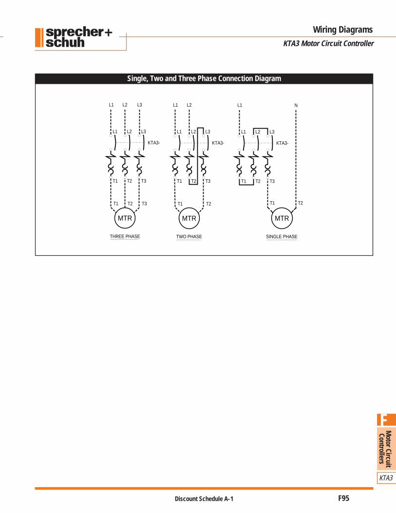
Single, Two and Three Phase Connection Diagram
CA7 Contactors Utilizing CV7 Mechanical Latch
Wiring Diagrams
KTA3 Motor Circuit Controller
T2
T3T2T1T1 T2 T3T2 T3T1
L3L2L1L3L2L1L3L2L1
N
MTR
T1
SINGLE PHASETWO PHASETHREE PHASE
L1
MTR
L1 L2
T2T1
MTR
L1 L2
T1 T3
L3
T2
KTA3-KTA3-KTA3-

Mot
or C
ircui
tCo
ntro
llers
KTA3
F
Discount Schedule A-1F96
1) DIN rail (EN 50022-35)2) KTA3-25 w/KT3-25-PE or KT3-25-PF3) KT3-25-PA4) KT3-25-AA or KT3-25-UA5) KTL3-65-N
Dimensions
Series KTA3 Motor Circuit Controller
88
45
88
45 2) 18 4)60
6444
45
9 3)
1)
606444
45
4
115
48 5)
1)
KTA3-25 Motor Circuit Controller KTL3-65-N Current Limiter with KTA3-25
KTA3-25-A2 and KTA3-25-A3 Supply Blocks KTA3-25 with Compact Bus Bar
88
45 4
34
5548
1)
1414
2444.5
12 12
24.5
17.5
12.3
107
The KTA3-25 can be mounted directly onto the KTA3-25-A2 Supply Block similar tothat shown in the dimension diagram for the Current Limiter.
KTA3-25-A2 KTA3-25-A3
Dimensions in millimeters except where noted

Motor Circuit
Controllers
KTA3
F
Discount Schedule A-1 F97
KTA3-25-KA(Z) Enclosure KTA3-25 Explosion Proof Starter - Type “E3”
Dimensions
Series KTA3 Motor Circuit Controller13
0
149
10
88
47,5
ø5
25
45
PG
21P
G16
87
45
30
ø4,8
3 1/2" 5 3/4"
6 3/
4"
Dimensions in millimeters except where noted
KT3-25-AS Adaptor Plate

Mot
or C
ircui
tCo
ntro
llers
KTA3
F
Discount Schedule A-1F98
Motor Circuit Controller
Series KTA3
Notes