KT-V Series - 光洋電子工業株式会社
12
536 Electronic Counter Tachometer Digital Timer Programmable Cam Electronic Counter / Controller SENSOR ENCODER COUNTER INFORMATION H M I P L C Visit our website ▼ http://www.koyoele.co.jp/english/ KOYO ELECTRONICS INDUSTRIES CO., LTD. GENERAL CATALOG 2018 Latest catalog (free) is available online. KT-V KT-V Series Features Digital Timer - The KT-V series has a compact DIN48□ size with an easy-to-see large display. - With characters represented by bright large red LEDs, 12 mm high characters can be clearly seen from a distance and an angle. - The green LED is used for the set value to differentiate it from the measured values. - The set value can be easily set to using the setting key corresponding to each digit, like using a digital switch. - The TC-V series can be easily operated owing to a selection method that uses DIP switches for basic functional setting and the digit keys for detailed setting. ■Features Protection Functions for Each Key Key protection can be set for each key to prevent unintended operation. Retentive Memory without Battery Backup An EEPROM is used for memory storage and a battery that does not require maintenance is used. Removable Terminal Block This removable terminal block improves maintenance. After wiring, the terminal block cover enhances safety. Power Source for High-capacity Sensor The AC type has a built-in 24 V DC, 60mA power source for sensors. Sensors such as encoders and proximity sensors can be connected to the counter. Multi-voltage Power Supply for AC Type The AC type covers supply voltages of 85 to 264 V AC and can be used for any power source. Various Time Range The 10 time ranges cover from 0.001 sec to 9,999 hr. For Various Applications Using 5 Operation Modes Delay On, delay OFF, one-shot, integrating, and flicker can be set as the operation mode. Key Protection Function to Prevent Malfunction The KT-V series has a built-in key protection function so that settings are not changed if the key is pressed by mistake during operation. Elapsed Time / Remaining Time Display As the time display, the elapsed time and the remaining time can be selected. Protection Fulfilling IP65 Sheet keys are used for the front panel, which enables users to safely operate the device even with wet or unclean hands. Conformity to CE and UL CE marking compliant and UL standard (UL508) certified product. CE Marking Compliant ■Model Number List Model Number Digit Power Source Power Source for Sensors 24 V DC, 60 mA Price KT-V4S 4 AC ● Open KT-V4S-C DC Open (Accessories) Mounting frame - Series Classification - Number of digits to display 4 : 4 digits - Output format S : With output - Power source type Blank : AC power C : DC power KT- V 4S-
Transcript of KT-V Series - 光洋電子工業株式会社

536
Electronic Counter
Tachometer
Digital Timer
Programmable Cam
Electronic Counter / Controller
SENSOR
ENCODER
COUNTER
INFORMATION
H M I
P L C
Visit our website ▼http://www.koyoele.co.jp/english/
KOYO ELECTRONICS INDUSTRIES CO., LTD.
GENERAL CATALOG 2018 Latest catalog (free) is available online.
KT-V
KT-V SeriesFeatures
Digital Timer- The KT-V series has a compact DIN48□ size with an easy-to-see
large display.- With characters represented by bright large red LEDs, 12 mm high characters can be clearly seen from a distance and an angle.- The green LED is used for the set value to differentiate it from the measured values.- The set value can be easily set to using the setting key corresponding to each digit, like using a digital switch.- The TC-V series can be easily operated owing to a selection method that uses
DIP switches for basic functional setting and the digit keys for detailed setting.
■FeaturesProtection Functions for Each KeyKey protection can be set for each key to prevent unintended operation.
Retentive Memory without Battery BackupAn EEPROM is used for memory storage and a battery that does not require maintenance is used.
Removable Terminal BlockThis removable terminal block improves maintenance. After wiring, the terminal block cover enhances safety.
Power Source for High-capacity SensorThe AC type has a built-in 24 V DC, 60mA power source for sensors. Sensors such as encoders and proximity sensors can be connected to the counter.
Multi-voltage Power Supply for AC TypeThe AC type covers supply voltages of 85 to 264 V AC and can be used for any power source.
Various Time RangeThe 10 time ranges cover from 0.001 sec to 9,999 hr.
For Various Applications Using 5 Operation ModesDelay On, delay OFF, one-shot, integrating, and flicker can be set as the operation mode.
Key Protection Function to Prevent MalfunctionThe KT-V series has a built-in key protection function so that settings are not changed if the key is pressed by mistake during operation.
Elapsed Time / Remaining Time DisplayAs the time display, the elapsed time and the remaining time can be selected.
Protection Fulfilling IP65Sheet keys are used for the front panel, which enables users to safely operate the device even with wet or unclean hands.
Conformity to CE and ULCE marking compliant and UL standard (UL508) certi�ed product.
CE Marking Compliant
■Model Number ListModel Number Digit Power Source
Power Source for Sensors 24 V DC, 60 mA
Price
KT-V4S4
AC ● Open
KT-V4S-C DC ̶ Open
(Accessories) Mounting frame
- Series Classification
- Number of digits to display 4 : 4 digits
- Output format S : With output
- Power source type Blank : AC power C : DC power
KT- V 4 S -

537
Electronic Counter
Tachometer
Digital Timer
Programmable Cam
Electronic Counter / Controller
SENSOR
ENCODER
COUNTER
INFORMATION
H M I
P L C
KOYO ELECTRONICS INDUSTRIES CO., LTD.
GENERAL CATALOG 2018The specifications and prices described in this catalog were valid when the catalog was issued.For the latest information, contact our sales persons or see our website.
KT-V
KT-V SeriesSpecifications
■ General SpecificationsItems
Rating
AC Power DC Power
Supply Voltage 100 to 240 V AC 12 to 24 V DC
Allowable Power Range 85 to 264 V AC 10 to 26.4 V DC
Power Consumption Approx. 11 VA Approx. 4 W
Power Source for Sensors
24 V DC (20 to 28 V) 60 mA (Ripple noise: 10% p-p or lower) ̶
Power Failure MemoryEEPROM Number of overwrite cycles: 100,000 cycles or more Storage time: 10 years
Ambient Temperature -10 to 50˚C
Storage Temperature -20 to 70˚C (No freezing)
Ambient Humidity 35 to 85%RH (No condensation)
Withstand Voltage2 kV AC 1 min (AC input, 0 V, between relay contacts) (DC power supply type: 0 V, only between relay contacts)
Vibration ResistanceEndurance Displacement amplitude: 0.5 mm, frequency: 10 to 55 Hz, 3 axial directions
Malfunction Displacement amplitude: 0.35 mm, frequency: 10 to 55 Hz, 3 axial directions
Impact ResistanceEndurance 490 m/s2 11 ms, 3 axial directions
Malfunction 98 m/s2 11 ms, 3 axial directions
Noise ResistanceBetween power supply terminals ±1.5 kV (Pulse width 1 μs, start-up 1 ns)
Between power supply terminals ±1.0 kV (Pulse width 1 μs, start-up 1 ns)
Protective Structure IP65 (Only the front panel part)
Weight Approx. 150 g Approx. 110 g
Terminal Block
Conforming cable 0.25 to 1.65 mm2
Conforming crimp terminal R1.25-3
Allowable tightening torque 0.5 Nm
■Performance SpecificationsItems Rating
Type Timer
Timing System On delay/Off delay/One-shot/Integrating/Flicker (With prediction output)
Digit 4 digits
Display Timing value display: Red LED, height of characters 12 mm. Set value display: Green LED, height of characters 7 mm
Time Range0.001 s to 9.999 s/0.01 s to 99.99 s/0.1 s to 999.9 s/1 s to 9,999 s/1 s to 99 min 59 s/1 min to 9,999 min /1 h to 9,999 h/1 min to 99 h 59 min/0.1 min to 999.9 min/0.1 h to 999.9 h
Display Format Elapsed time display / Remaining time display
Timer Accuracy 0.013% or ±15 ms (Whichever is larger)
Input
Input logic: Negative logic (No-voltage input)/Positive logic (Voltage input)
Input resistance: Positive logic 15 kΩ Negative logic 3.3 kΩ (AC power)/1.8 kΩ (DC power)
Input voltage: "L" 0 to 3 V "H" 7 to 30 V
Start Input Response 15 ms/5 ms/1 ms or less
External Reset Minimum signal width: 5 ms
OutputNon-contact output: NPN open collector output, 24 V 100 mA, withstand voltage: 35 V, residual voltage: 1.5 V or lower
Contact output: 1 transfer (1 c), 220 V AC 2 A (Resistance load)
Output Time (Flicker) Variable from 10 to 9,990 ms, every 10 ms
Key Protection Any key setting is enabled.
Installation Method Dedicated to embedded installation (Terminal block connection)

538
Electronic Counter
Tachometer
Digital Timer
Programmable Cam
Electronic Counter / Controller
SENSOR
ENCODER
COUNTER
INFORMATION
H M I
P L C
Visit our website ▼http://www.koyoele.co.jp/english/
KOYO ELECTRONICS INDUSTRIES CO., LTD.
GENERAL CATALOG 2018 Latest catalog (free) is available online.
KT-V
KT-V SeriesOutput Operation
■Output Operation ChartOn Delay
Off Delay
One-shot
Integrating
FlickerFlickering is set in the setup mode.
Set Value
Contact Output
Start
0
ON
OFFON
OFFON
OFF
Non-contact OutputON
OFF
Elapsed Time DisplayRemaining Time Display
Reset
オンディレー
オフディレー
フリッカ
Set Value
Contact Output
Start
0
ON
OFFON
OFF
ON
OFF
Non-contact OutputON
OFF
Elapsed Time Display
Reset
Set Value
Contact Output
Start
0
ON
OFFON
OFFON
OFF
Non-contact OutputON
OFF
Elapsed Time DisplayRemaining Time Display
Remaining Time Display
Reset
: Prediction Set Value
t t t t
The output time "t" can be changed from 10 to 9,990 ms (100 ms before shipment).
Remaining Time Display
積 算
Set Value
Contact Output
Start
0
ON
OFFON
OFFON
OFF
Non-contact OutputON
OFF
Power SupplyON
OFF
Elapsed Time Display
Reset
The prediction set value should be smaller than the set value.If the prediction setting value exceeds the set value, the prediction output (non-contact output) turns ON (or OFF) simultaneously with the start of the timer operation.
When the prediction set value is "0," non-contact output becomes the same as the output operation of contact output.
ワンショット
Set Value
Preset Values
Preset Values
Preset Values
Preset Values
Preset Values
Contact Output
Start
0
ON
OFFON
OFFON
OFF
Non-contact OutputON
OFF
Elapsed Time Display
Reset
Remaining Time Display
: Prediction Set Value
1SW 2
OFF ON
1SW 2
ON ON
1SW 2
OFF OFF
1SW 2
ON OFF
Set Value
Contact Output
Start
0
ON
OFFON
OFFON
OFF
Non-contact OutputON
OFF
Elapsed Time DisplayRemaining Time Display
Reset
オンディレー
オフディレー
フリッカ
Set Value
Contact Output
Start
0
ON
OFFON
OFF
ON
OFF
Non-contact OutputON
OFF
Elapsed Time Display
Reset
Set Value
Contact Output
Start
0
ON
OFFON
OFFON
OFF
Non-contact OutputON
OFF
Elapsed Time DisplayRemaining Time Display
Remaining Time Display
Reset
: Prediction Set Value
t t t t
The output time "t" can be changed from 10 to 9,990 ms (100 ms before shipment).
Remaining Time Display
積 算
Set Value
Contact Output
Start
0
ON
OFFON
OFFON
OFF
Non-contact OutputON
OFF
Power SupplyON
OFF
Elapsed Time Display
Reset
The prediction set value should be smaller than the set value.If the prediction setting value exceeds the set value, the prediction output (non-contact output) turns ON (or OFF) simultaneously with the start of the timer operation.
When the prediction set value is "0," non-contact output becomes the same as the output operation of contact output.
ワンショット
Set Value
Preset Values
Preset Values
Preset Values
Preset Values
Preset Values
Contact Output
Start
0
ON
OFFON
OFFON
OFF
Non-contact OutputON
OFF
Elapsed Time Display
Reset
Remaining Time Display
: Prediction Set Value
1SW 2
OFF ON
1SW 2
ON ON
1SW 2
OFF OFF
1SW 2
ON OFF

539
Electronic Counter
Tachometer
Digital Timer
Programmable Cam
Electronic Counter / Controller
SENSOR
ENCODER
COUNTER
INFORMATION
H M I
P L C
KOYO ELECTRONICS INDUSTRIES CO., LTD.
GENERAL CATALOG 2018The specifications and prices described in this catalog were valid when the catalog was issued.For the latest information, contact our sales persons or see our website.
KT-V
KT-V SeriesConnection
■Terminal Connection DiagramsKT-V4S KT-V4S-C
* Non-contact output (OUT terminal) is also used for prediction output.
* Do not connect anything to unconnected terminals.
■Input/Output Circuit DiagramsAC Power DC Power
KT-V4S
Start Input Start Input
KT-V4S-C
※予報出力はNon-contact Output(OUT端子)と兼用です。
2 3 5
OUT 71
8 9 10 11 12
RReset Input
24 V DC, 60 mA Power Source for Sensor
IN 0 V
COM N.C. N.O.
100 to 240 V AC Power SourceContact Output
Non-contact Output
OUTNon-contact Output
71
3 5
8 9 10 11 12
RReset Input
IN 0 V
COM N.C. N.O.Contact Output
12 to 24 V DC Power Source+ −
AC電源形 DC電源形
2
3
7
9
10
1
5 V
3.3 k
47 k
22 k
22 k
5 V3.3 k
47 k
Internal 24 V
ON During Negative Logic Input
OUT
Power Source for Sensor24 V DC
StartInput
ResetInput
N.C.
COM
N.O.
8
5 0 V
3
7
9
10
1
5 V
1.8 k
47 k
22 k
22 k
5 V1.8 k
47 k
Internal 24 V
ON During Negative Logic Input
OUT
StartInput
ResetInput
N.C.
COM
N.O.
8
5 0 V
24 V DC11
12
+
−

540
Electronic Counter
Tachometer
Digital Timer
Programmable Cam
Electronic Counter / Controller
SENSOR
ENCODER
COUNTER
INFORMATION
H M I
P L C
Visit our website ▼http://www.koyoele.co.jp/english/
KOYO ELECTRONICS INDUSTRIES CO., LTD.
GENERAL CATALOG 2018 Latest catalog (free) is available online.
KT-V
KT-V SeriesConnection
■Input Connection ExamplesNPN Open Collector Output Proximity Sensor- Input logic: Negative logic (No-voltage input) (neg) 《Recommended proximity sensor: APS□-□-N/E》
2-wire DC System Proximity Sensor- Input logic: Negative logic (No-voltage input) (neg) 《Recommended proximity sensor: APS□-□-Z 》
* In the case of the DC power source type, the supply voltage should be not less than 20 V.
Switch Relay- Input logic: Negative logic (No-voltage input) (neg) - Start input response: 15 ms* Because there is large input current, this connection is recommended.
■Output Connection ExamplesNPN Open Collector Output
Voltage Output or PNP Open Collector Output Proximity Sensor- Input logic: Positive logic (Voltage input) (pos) 《Recommended proximity sensor: APS□-□-E2》
- Input logic: Positive logic (Voltage input) (pos)- Start input response: 15 ms
* There is no power source for sensors in the case of the DC power source type.
Use a separate external power source.
Contact Output
電圧出力形またはPNPオープンコレクタ出力形近接センサの場合NPNオープンコレクタ出力形近接センサの場合
DC2線式近接センサの場合
Start Input
Reset Input
0 V
Start
Reset
Power Source for Sensor24 V DC*
Start Input
Reset Input
0 V
Start
Reset
2
3
5
7
2
3
5
7
Power Source for Sensor24 V DC*
Brown
Black
Blue
Black
Brown
Black
Blue
Black
Start Input
Reset Input
0 V
Start
Reset
3
5
7
スイッチ・リレーの場合
Start Input
Reset Input
0 V
Start
Reset
Power Source for Sensor24 V DC*
Start Input
Reset Input
0 V
※DC電源タイプにはありません。別途、外部電源を使用ください。
2
3
5
7
3
5
7
Start
Reset
1
5
LoadOUT
0V
8
9
COM
N.C.
N.O.
+−
Power Source for LoadRated 24 V DC
NPNオープンコレクタ出力の場合 接点出力の場合
Relay Drive Possible
10
Power Source for Load
Load
Load
1
5
LoadOUT
0V
8
9
COM
N.C.
N.O.
+−
Power Source for LoadRated 24 V DC
NPNオープンコレクタ出力の場合 接点出力の場合
Relay Drive Possible
10
Power Source for Load
Load
Load

541
Electronic Counter
Tachometer
Digital Timer
Programmable Cam
Electronic Counter / Controller
SENSOR
ENCODER
COUNTER
INFORMATION
H M I
P L C
KOYO ELECTRONICS INDUSTRIES CO., LTD.
GENERAL CATALOG 2018The specifications and prices described in this catalog were valid when the catalog was issued.For the latest information, contact our sales persons or see our website.
KT-V
KT-V SeriesEach Part Name and Function
■Key Operation1. Changes the preset value Every time a digit key is pressed, 1 is added to the preset value of the
corresponding digit.
Approx. 1 second after a digit key is released, the set value is entered. * In the case of ■ digit of sexagesimal scale display □□: ■□ (Minute) (Second)
(Hour) (Minute)
2. Resetting the timing value If the [RST] key is pressed (response time is 0.1 s), the timing value is
reset. If the [RST] key is pressed, the timing value becomes the set value in the remaining time display mode and "0" in the passage display mode.
3. Key protection The key protection can be individually set for each operation key. If a key
for which the key protection is set is pressed in the run mode, the LED corresponding to the pressed key blinks to notify that the operation is prohibited.
Since the protection is set to all keys before shipment, if the power is supplied when DIP switch 7 is ON, operation of all keys is prohibited.
■Panel Explanation① Output display (Red) - Operation mode Lights up when the output is ON. Blinks when the prediction output is ON.
② Protection display (Red) - Operation mode Blinks when the key is protected. (Only when the key is ON)
- Setup mode D isp lays t he se t con ten t s o f key
protection.
⑦ RST key - Operation mode Resets the discrete value. (0 in increment mode, preset value in decrement
mode)
- Setup mode Select the setting item.
③ Discrete value display (Red) - Operation mode Displays the discrete value. - Setup mode Displays the set contents.
④ Unit display - Operation mode Display the units of time. h: hour / m: minute / s: second
⑤ Set value display (Green) - Operation mode Displays the set value. - Setup mode Displays the setting item.
⑥ Digit key - Operation mode Changing the set value * If approx. 1 sec passes without any key input after the
set value has been changed, the set value becomes effective.
- Setup mode Selects the set contents.
0 1 2 3 4 5 6 7 8 9*
Example: When the counter is “123”
Press the 1 key and the 124
Press the 2 key and the 134
Press the 3 key and the 234
1
2
3
0 1 2 3 4 5 6 7 8 9*
Example: When the counter is “123”
Press the 1 key and the 124
Press the 2 key and the 134
Press the 3 key and the 234
1
2
3
Time Range
□□□□s
□□□□m
□□□□h
□□m□□s
□□ h□□m
0 to 9999
0 to 9999
0 to 9999
0:00 to 99 :59 0:00 to 99 :59
Timing / Set Value Display Unit Display
mh :: s
mh :: s
mh :: s
mh :: s
mh :: s
⑦
②
①
③
④
⑥
⑤
Time Range
□□□□s
□□□□m
□□□□h
□□m□□s
□□ h□□m
0 to 9999
0 to 9999
0 to 9999
0:00 to 99 :59 0:00 to 99 :59
Timing / Set Value Display Unit Display
mh :: s
mh :: s
mh :: s
mh :: s
mh :: s
⑦
②
①
③
④
⑥
⑤

542
Electronic Counter
Tachometer
Digital Timer
Programmable Cam
Electronic Counter / Controller
SENSOR
ENCODER
COUNTER
INFORMATION
H M I
P L C
Visit our website ▼http://www.koyoele.co.jp/english/
KOYO ELECTRONICS INDUSTRIES CO., LTD.
GENERAL CATALOG 2018 Latest catalog (free) is available online.
KT-V
KT-V SeriesEach Part Name and Function
■DIP Switch Setting- Use the DIP switches at the top of the timer for setting.- Before operating the DIP switches, be sure that the power is turned off.
The switches do not respond to setting changes while the power is on.- When a DIP switch is changed, be sure to press the [RST] key in the
operation mode to reset the count value.
Output ModeSelect the output mode with DIP switches 1 and 2. The �icker mode that is not included in the items is selected in the setup mode.
Time RangeSelect the time range with DIP switches 3, 4, and 5. The time range that is not included in the items is selected in the setup mode.
Display FormatSelect the display format with DIP switch 6.
Key ProtectionSelect whether to engage the key protection or not with DIP switch 7. To engage protection, after setting each key in the setup mode, set DIP switch 7 in the ON position and supply the power again to enable the protection. All keys are set for protection before shipment.
Operation ModeSelect the setup mode and the operation mode with DIP switch 8.
Dip switch
Selecting the Output Mode
Selecting the Time Range
Selecting the Display Format
Selects the Key Protection.
Selects the Operation Mode.
* The DIP switches are all set in the OFF position before shipment.
出力モード
時間レンジ
Display Format
Elapsed Time Display
Remaining Time Display
SW6
ON
OFF
表示方式
Operation Mode
Setup Mode
Operation Mode
SW8
ON
OFF
Key Protection
Use
Not Use
SW7
ON
OFF
動作モード
キープロテクト
Time Range
□□h□□m
□□□□h
□□□□m
□□m□□s
□□□□s
□□□.□s
□□.□□s
□.□□□s
SW4
ON
ON
OFF
OFF
ON
ON
OFF
OFF
SW3 SW5
ON
OFF
ON
OFF
ON
OFF
ON
OFF
ON
ON
ON
ON
OFF
OFF
OFF
OFF
Operation
Integrating
One-shot
Delay OFF
Delay On
SW2
ON
OFF
ON
OFF
SW1
ON
ON
OFF
OFF

543
Electronic Counter
Tachometer
Digital Timer
Programmable Cam
Electronic Counter / Controller
SENSOR
ENCODER
COUNTER
INFORMATION
H M I
P L C
KOYO ELECTRONICS INDUSTRIES CO., LTD.
GENERAL CATALOG 2018The specifications and prices described in this catalog were valid when the catalog was issued.For the latest information, contact our sales persons or see our website.
KT-V
■Setup ModeMake settings that cannot be selected with the DIP switches, in the setup mode.
Setup Mode Setting Items(1) Start input response …… 1/5/15 ms(2) Input logic …………… Positive logic, negative logic(3) Output mode …………… Flicker mode, DIP switch(4) Time range …………… 0.0 minute /0.0 time, DIP switch(5) Output time …………… Set the output time of the �icker mode from
10 to 9,990 ms (in unit of 10 ms).(6) Prediction output ……… Set the offset value for the set value.(7) Reset key protection …… Set the lock for the reset key.(8) Digit key protection …… Set the lock for the digit keys.
Switching Between the Setup Mode and the Operation Mode
① When DIP switch 8 is in the ON position and the power is turned on, the setup mode starts.
② When the DIP switch 8 is in the OFF position and the power is turned on, the operation mode starts.
Operation of the Setup ModeInitialize the setup mode using the menu as shown in the table on the right.(Use the digit keys for all settings.)
- Other than the �icker mode, skip the setting items with an * mark.- When the default setting is changed in the setup mode, be sure to press
the [RST] key in the operation mode to reset the timing value.- The set contents become effective when moving to the next menu via the
[RST] key.- The key protection setting becomes effective in AND conditions from DIP
switch 7. If you want to make the protection effective, set DIP switch 7 in the ON
position.
KT-V SeriesEach Part Name and Function
Operating Mode Setup Mode
①
②
④ Time range setting(rang)
: 000.0: Select 0.0 minute.: 000.0: Select 0.0 hour.: dip :— Set the DIP switch.
123
Digit key is disabled as the setting is performed in units of 10 ms.
0. 1 0 0 s4 3 2 1
0 . 0 . 0 . 04 3 2 1
1
⑤ *Output time setting (outt)
⑦ Reset key protection setting (rpro)
Select whether to lock the reset key or not.Digit key: K/P display part
RST
RST
RST
RST
RST
RST
⑧ Digit key protection setting (ppro)
Select whether to lock the reset key or not.Digit key: K/P display part
: □□□□■ (Lock)/ (Unlock): □□□■□ (Lock)/ (Unlock)
1
: ■□□□□ (Lock)1: □□□□□ (Unlock)2
22: □□■□□ (Lock)/ (Unlock)3: □■□□□ (Lock)/ (Unlock)4
⑥ Prediction output setting (set )
a
Discrete value display part
Digit key
Discrete value display part
Digit key
Initial value: 100ms
Initial value: 0
Initial value: Locked
Initial value: Locked
Initial value: 3□
③ Output mode setting (t-op)
: F Select the flicker mode.: dip Set the DIP switch.
12
Initial value: 2□
Initial value: 3□
② Input logic setting (si g)
: pos Positive logic: neg Negative logic
12
Initial value: 2□
RST
RST
① Start input response setting(int)
: 1 Select a 1 ms response.: 5 Select a 5 ms response.: 15 Select a 15 ms response.
123
m
h
To the first menuby pressing the reset key
To the next menuby pressing the reset key
11 : Lit when disabled
: Enabled when out
Digit key K/P display part: Not use: Use

544
Electronic Counter
Tachometer
Digital Timer
Programmable Cam
Electronic Counter / Controller
SENSOR
ENCODER
COUNTER
INFORMATION
H M I
P L C
Visit our website ▼http://www.koyoele.co.jp/english/
KOYO ELECTRONICS INDUSTRIES CO., LTD.
GENERAL CATALOG 2018 Latest catalog (free) is available online.
KT-V
3. Change the set contents
5. Switching to the operation mode When setup is completed in the setup mode, turn the power off, set DIP
switch 8 in the OFF position (to the operation mode) and turn ON the power.
6. Start the operation mode When the setting is changed in the setup mode, be sure to press the [RST]
key after turning the power ON to reset the timing value.
■Operation ModeChanges the Preset ValueChange the preset value from "2:00" to "1:30". The preset value becomes effective approx. 1 second after the change is made.
■Washing Time ControlIf the start switch is pressed, washing is performed for the set time.
1. Setting DIP switches Turn the power off before operating the DIP switches.
2. Switching to the setup mode Set DIP switch 8 in the ON position, and turn the power on.
Setting item
Setting Item Contents
Output Mode One-shot
Time Range □□minute□□second
Display Format Remaining time display
Key ProtectionReset key ProhibitionSecond key
KT-V SeriesExample of Operation
K/P
OUT mh :: s
RST 134 2
K/P
OUT mh :: s
RST 134 2
K/P
OUT mh :: s
RST 134 2
K/P
OUT mh :: s
RST 134 2
Before Changing
Press setting key nine times or continue to press and hold the key to display "1. "
3 Press setting key three times or continue to press and hold the key to display "3. "
2
Change Complete
・Set DIP switch 1 is in the ON position.
・Set DIP switch 2 is in the OFF position.
・Set DIP switch 3 is in the ON position.
・Set DIP switch 4 and 5 is in the OFF position.
・Set DIP switch is in the ON position.
① Select the output mode and one-shot.
② Select the time range: □□min □□sec
③ Select the key protection.
K/POUT
K/POUT
K/POUT
K/POUT
K/POUT
K/POUT
K/POUT
④ Time range Setting screen
⑥ Reset key protection Setting screen
⑦ Digit key protection Setting screen
Press the key and key to enable settings.
4 3
⑤ Prediction output setting Setting screen
RST
RST
① Start input response Setting screen
Change to the initial value.
Change to the initial value.
RSTChange to the initial value.
RSTChange to the initial value.
RSTChange to the initial value.
RSTChange to the initial value.
This setting is complete.RST
③ Setting screen
② Setting screenInput logic
Output mode
To the next menu by pressing
the reset key
Press the reset keyto end setup.

545
Electronic Counter
Tachometer
Digital Timer
Programmable Cam
Electronic Counter / Controller
SENSOR
ENCODER
COUNTER
INFORMATION
H M I
P L C
KOYO ELECTRONICS INDUSTRIES CO., LTD.
GENERAL CATALOG 2018The specifications and prices described in this catalog were valid when the catalog was issued.For the latest information, contact our sales persons or see our website.
KT-V
KT-V SeriesError Code Display/Option
■Common ErrorsError Code Error Name Error details Corrective Action
Memory data errorPreset value / Set value and the contents of the setup mode changed.
Press the [RST] key and delete the error indication.The measured value and the timing value become "0", the preset value and the set value become "5000", and the contents of the setup mode revert back to the preshipment defaults.
■OptionOption Model Number Contents Price
Rubber Gasket KC-48PIf installed between the installation panel and KT-V, it prevents the intrusion of water into the control panel.
Open
Front Cover KC-48CIf installed to the front panel, it protects the counter from exposure to dirt, etc. Material: Soft silicon rubber Key operation is enabled with the front cover installed.
Open

546
Electronic Counter
Tachometer
Digital Timer
Programmable Cam
Electronic Counter / Controller
SENSOR
ENCODER
COUNTER
INFORMATION
H M I
P L C
Visit our website ▼http://www.koyoele.co.jp/english/
KOYO ELECTRONICS INDUSTRIES CO., LTD.
GENERAL CATALOG 2018 Latest catalog (free) is available online.
KT-V
KT-V SeriesPrecautions
■How to Mount and Remove the Main BodyHow to Mount the Main Body How to Mount the Terminal Block and the Terminal Block Cover
How to Remove the Main Body
① Insert the main body into the attachment bore of the panel.
② Attach the mounting frame from the backside.
Mounting Frame: The frame can be mounted both in the longitudinal and transverse directions.
Terminal Block
Body
Fixing Screw
Terminal Block Cover
- As the screw for anchoring the terminal block, only use the anchoring screw used in shipping.- Make sure that the allowable tightening torque is 0.3 Nm.- Mount the terminal block cover after the wiring is completed.
① Pinch the levers to spread them 2 to 3 mm outwards.② Pull out the frame while the levers are spread.
■Precautions in Use (1) The power source 0 V terminal ⑫ and the input common 0 V terminal ⑤ of the DC type are internally short-circuited.
(5) Rather than gradually increasing the supply voltage, apply the rated voltage at once using a switch or relay.
(3) When using the 2-wire DC system proximity sensor, set the input logic to negative logic.
(4) If the preset value / set value is changed during measurement / timing, the changed value becomes effective approx. 1 second after key input.
(5) Enter the set contents of the DIP switches and the setup mode in the data sheet attached to the main body and keep it for maintenance.
(6) Do not use the counter in the following environments.- Any place where the ambient temperature exceeds 50˚C or falls to
-10˚C or lower.- Any place where the ambient humidity exceeds 85% or condensation
occurs due to rapid temperature change.- Any place that is exposed to dust, iron powder, and corrosive gas.- Any place that is exposed to sunlight.- Any place where there are large vibrations or shocks.
(7) When performing a dielectric voltage test or insulation resistance test, separate the main body from the control circuit.
(8) When the power is shut down, the internal EEPROM is written. Since the number of writing cycles in the EEPROM is not more than
100,000, do not use the tachometer by highly frequent power source operations.
■Cautions in Wiring - Wire cables separately from power lines. - When using the counter in a place where a lot of noise is generated,
separate the main body of the KT-V and the wiring from the noise sources as far as possible.
- Do not use an unused terminal as a relay terminal. - It is recommended to use a crimp terminal for connections. - When wiring the cable to the terminals ① and ⑦, if the crimp terminal
has a fork shape, do not attach it diagonally. For diagonal attachment, use a round crimp terminal.
If the crimp terminal is diagonally attached, the contact with the terminal becomes insufficient.Therefore, attach the crimp terminal horizontally from the side as shown in the figure above.
In the Case of a Forked Crimp Terminal
In the Case of a Round Crimp Terminal
115.464
① Insert the main body into the attachment bore of the panel.
② Attach the mounting frame from the backside.
Mounting Frame: The frame can be mounted both in the longitudinal and transverse directions.
Terminal Block
Body
Fixing Screw
Terminal Block Cover
- As the screw for anchoring the terminal block, only use the anchoring screw used in shipping.- Make sure that the allowable tightening torque is 0.3 Nm.- Mount the terminal block cover after the wiring is completed.
① Pinch the levers to spread them 2 to 3 mm outwards.② Pull out the frame while the levers are spread.
547
Electronic Counter
Tachometer
Digital Timer
Programmable Cam
Electronic Counter / Controller
SENSOR
ENCODER
COUNTER
INFORMATION
H M I
P L C
KOYO ELECTRONICS INDUSTRIES CO., LTD.
GENERAL CATALOG 2018The specifications and prices described in this catalog were valid when the catalog was issued.For the latest information, contact our sales persons or see our website.
KT-V
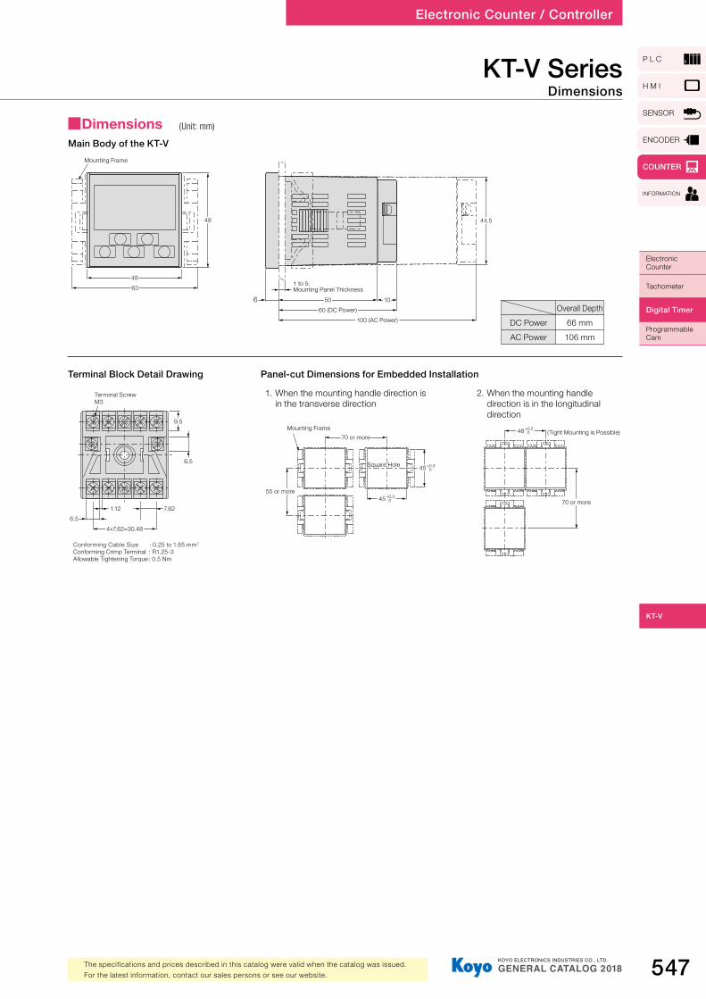
KT-V SeriesDimensions
Panel-cut Dimensions for Embedded Installation
1. When the mounting handle direction is in the transverse direction
2. When the mounting handle direction is in the longitudinal direction
Terminal Block Detail Drawing
Main Body of the KT-V
DC PowerAC Power
Overall Depth66 mm106 mm
4863
Mounting Frame
48
5060 (DC Power)
100 (AC Power)
10
1 to 5: Mounting Panel Thickness
6
44.5
Conforming Cable Size : 0.25 to 1.65 mm2
Conforming Crimp Terminal : R1.25-3Allowable Tightening Torque : 0.5 Nm
9.5
6.5
Terminal ScrewM3
1.12 7.626.5
4×7.62=30.48
55 or more
45 +0.3 0
45 +0.3 0
Mounting Frame70 or more
Square Hole
(Tight Mounting is Possible)
70 or more
48 +0.2 0
■Dimensions (Unit: mm)


![探秘文化之都 - Crystal Cruises...羅馬 /B~`] « ] aL] 印度洋 大西洋 太平洋 'O] 香港 / 澳門 聖彼德堡 阿布扎比 Y×] 風光與眼界 探秘文化之都 探訪三個享譽全球的首都城市,開啟一場歷史氣息與現代都市的完美融合之旅。漫步於藝術、文化和商業中心,](https://static.fdocuments.us/doc/165x107/5f0ade387e708231d42dbc13/coeef-crystal-ce-b-al-e-.jpg)