
KR CYBERTECH nano - wtech.com.t CYBERTEC… · Robots KR CYBERTECH nano Specification KUKA Roboter...
153
Robots KR CYBERTECH nano Specification KUKA Roboter GmbH Issued: 25.07.2016 Version: Spez KR CYBERTECH nano V1 KR CY- BERTECH nano
Transcript of KR CYBERTECH nano - wtech.com.t CYBERTEC… · Robots KR CYBERTECH nano Specification KUKA Roboter...

Robots
KR CYBERTECH nano
Specification
KUKA Roboter GmbH
Issued: 25.07.2016
Version: Spez KR CYBERTECH nano V1
KR CY-
BERTECH
nano
KR CYBERTECH nano
2 / 153 Issued: 25.07.2016 Version: Spez KR CYBERTECH nano V1
© Copyright 2016
KUKA Roboter GmbHZugspitzstraße 140D-86165 AugsburgGermany
This documentation or excerpts therefrom may not be reproduced or disclosed to third parties without the express permission of KUKA Roboter GmbH.
Other functions not described in this documentation may be operable in the controller. The user has no claims to these functions, however, in the case of a replacement or service work.
We have checked the content of this documentation for conformity with the hardware and software described. Nevertheless, discrepancies cannot be precluded, for which reason we are not able to guarantee total conformity. The information in this documentation is checked on a regular basis, how-ever, and necessary corrections will be incorporated in the subsequent edition.
Subject to technical alterations without an effect on the function.
Translation of the original documentation
KIM-PS5-DOC
Publication: Pub Spez KR CYBERTECH nano (PDF) enBook structure: Spez KR CYBERTECH nano V2.1Version: Spez KR CYBERTECH nano V1
3 / 153Issued: 25.07.2016 Version: Spez KR CYBERTECH nano V1
Contents
1 Introduction .................................................................................................. 7
1.1 Industrial robot documentation ................................................................................... 71.2 Representation of warnings and notes ...................................................................... 7
2 Purpose ........................................................................................................ 9
2.1 Target group .............................................................................................................. 92.2 Intended use .............................................................................................................. 9
3 Product description ..................................................................................... 11
3.1 Overview of the robot system .................................................................................... 113.2 Description of the manipulator ................................................................................... 12
4 Technical data .............................................................................................. 15
4.1 Technical data, overview ........................................................................................... 154.2 Technical data, KR 10 R1420 .................................................................................... 164.2.1 Basic data, KR 10 R1420 ..................................................................................... 164.2.2 Axis data, KR 10 R1420 ....................................................................................... 174.2.3 Payloads, KR 10 R1420 ....................................................................................... 194.2.4 Loads acting on the mounting base KR 10 R1420 ............................................... 234.2.5 Transport dimensions, KR 10 R1420 .................................................................... 244.3 Technical data, KR 8 R1620 ...................................................................................... 254.3.1 Basic data, KR 8 R1620 ....................................................................................... 254.3.2 Axis data, KR 8 R1620 ......................................................................................... 264.3.3 Payloads, KR 8 R1620 ......................................................................................... 294.3.4 Loads acting on the mounting base KR 8 R1620 ................................................. 334.3.5 Transport dimensions, KR 8 R1620 ...................................................................... 354.4 Technical data, KR 6 R1820 ...................................................................................... 354.4.1 Basic data, KR 6 R1820 ....................................................................................... 354.4.2 Axis data, KR 6 R1820 ......................................................................................... 364.4.3 Payloads, KR 6 R1820 ......................................................................................... 394.4.4 Loads acting on the mounting base KR 6 R1820 ................................................. 434.4.5 Transport dimensions, KR 6 R1820 ...................................................................... 444.5 Technical data, KR 10 R1420 HP .............................................................................. 454.5.1 Basic data, KR 10 R1420 HP ............................................................................... 454.5.2 Axis data, KR 10 R1420 HP ................................................................................. 464.5.3 Payloads, KR 10 R1420 HP ................................................................................. 494.5.4 Loads acting on the mounting base KR 10 R1420 HP ......................................... 534.5.5 Transport dimensions, KR 10 R1420 HP .............................................................. 544.6 Technical data, KR 8 R1620 HP ................................................................................ 554.6.1 Basic data, KR 8 R1620 HP ................................................................................. 554.6.2 Axis data, KR 8 R1620 HP ................................................................................... 564.6.3 Payloads, KR 8 R1620 HP ................................................................................... 594.6.4 Loads acting on the mounting base KR 8 R1620 HP ........................................... 634.6.5 Transport dimensions, KR 8 R1620 HP ................................................................ 654.7 Technical data, KR 6 R1820 HP ................................................................................ 654.7.1 Basic data, KR 6 R1820 HP ................................................................................. 654.7.2 Axis data, KR 6 R1820 HP ................................................................................... 66
Contents
4 / 153 Issued: 25.07.2016 Version: Spez KR CYBERTECH nano V1
KR CYBERTECH nano
4.7.3 Payloads, KR 6 R1820 HP ................................................................................... 694.7.4 Loads acting on the mounting base KR 6 R1820 HP ........................................... 734.7.5 Transport dimensions, KR 6 R1820 HP ............................................................... 744.8 Plates and labels ....................................................................................................... 754.9 REACH duty to communicate information acc. to Art. 33 of Regulation (EC) 1907/2006 774.10 Stopping distances and times .................................................................................... 784.10.1 General information .............................................................................................. 784.10.2 Terms used .......................................................................................................... 784.10.3 Stopping distances and times, KR 10 R1420 ....................................................... 794.10.3.1 Stopping distances and stopping times for STOP 0, axis 1 to axis 3 .............. 794.10.3.2 Stopping distances and stopping times for STOP 1, axis 1 ............................ 814.10.3.3 Stopping distances and stopping times for STOP 1, axis 2 ............................ 834.10.3.4 Stopping distances and stopping times for STOP 1, axis 3 ............................ 854.10.4 Stopping distances and times, KR 8 R1620 ......................................................... 854.10.4.1 Stopping distances and stopping times for STOP 0, axis 1 to axis 3 .............. 854.10.4.2 Stopping distances and stopping times for STOP 1, axis 1 ............................ 864.10.4.3 Stopping distances and stopping times for STOP 1, axis 2 ............................ 884.10.4.4 Stopping distances and stopping times for STOP 1, axis 3 ............................ 904.10.5 Stopping distances and times, KR 6 R1820 ......................................................... 904.10.5.1 Stopping distances and stopping times for STOP 0, axis 1 to axis 3 .............. 904.10.5.2 Stopping distances and stopping times for STOP 1, axis 1 ............................ 914.10.5.3 Stopping distances and stopping times for STOP 1, axis 2 ............................ 934.10.5.4 Stopping distances and stopping times for STOP 1, axis 3 ............................ 954.10.6 Stopping distances and times, KR 10 R1420 HP ................................................. 954.10.6.1 Stopping distances and stopping times for STOP 0, axis 1 to axis 3 .............. 954.10.6.2 Stopping distances and stopping times for STOP 1, axis 1 ............................ 964.10.6.3 Stopping distances and stopping times for STOP 1, axis 2 ............................ 984.10.6.4 Stopping distances and stopping times for STOP 1, axis 3 ............................ 1004.10.7 Stopping distances and times, KR 8 R1620 HP ................................................... 1004.10.7.1 Stopping distances and stopping times for STOP 0, axis 1 to axis 3 .............. 1004.10.7.2 Stopping distances and stopping times for STOP 1, axis 1 ............................ 1014.10.7.3 Stopping distances and stopping times for STOP 1, axis 2 ............................ 1034.10.7.4 Stopping distances and stopping times for STOP 1, axis 3 ............................ 1054.10.8 Stopping distances and times, KR 6 R1820 HP ................................................... 1054.10.8.1 Stopping distances and stopping times for STOP 0, axis 1 to axis 3 .............. 1054.10.8.2 Stopping distances and stopping times for STOP 1, axis 1 ............................ 1064.10.8.3 Stopping distances and stopping times for STOP 1, axis 2 ............................ 1084.10.8.4 Stopping distances and stopping times for STOP 1, axis 3 ............................ 110
5 Safety ............................................................................................................ 111
5.1 General ...................................................................................................................... 1115.1.1 Liability ................................................................................................................. 1115.1.2 Intended use of the industrial robot ...................................................................... 1125.1.3 EC declaration of conformity and declaration of incorporation ............................. 1125.1.4 Terms used .......................................................................................................... 1135.2 Personnel .................................................................................................................. 1135.3 Workspace, safety zone and danger zone ................................................................ 1145.4 Overview of protective equipment ............................................................................. 1155.4.1 Mechanical end stops ........................................................................................... 1155.4.2 Mechanical axis range limitation (optional) ........................................................... 115
5 / 153Issued: 25.07.2016 Version: Spez KR CYBERTECH nano V1
Contents
5.4.3 Axis range monitoring (optional) ........................................................................... 1155.4.4 Options for moving the manipulator without drive energy ..................................... 1165.4.5 Labeling on the industrial robot ............................................................................. 1165.5 Safety measures ........................................................................................................ 1175.5.1 General safety measures ...................................................................................... 1175.5.2 Transportation ....................................................................................................... 1185.5.3 Start-up and recommissioning .............................................................................. 1185.5.4 Manual mode ........................................................................................................ 1195.5.5 Automatic mode .................................................................................................... 1205.5.6 Maintenance and repair ........................................................................................ 1205.5.7 Decommissioning, storage and disposal .............................................................. 1225.6 Applied norms and regulations .................................................................................. 122
6 Planning ....................................................................................................... 125
6.1 Information for planning ............................................................................................. 1256.2 Mounting base ........................................................................................................... 1256.3 Machine frame mounting ........................................................................................... 1276.4 Connecting cables and interfaces .............................................................................. 1296.5 Internal energy supply system ................................................................................... 132
7 Transportation ............................................................................................. 137
7.1 Transporting the robot ................................................................................................ 137
8 Options ......................................................................................................... 141
8.1 Release device (optional) .......................................................................................... 141
9 KUKA Service .............................................................................................. 143
9.1 Requesting support .................................................................................................... 1439.2 KUKA Customer Support ........................................................................................... 143
Index ............................................................................................................. 151

6 / 153 Issued: 25.07.2016 Version: Spez KR CYBERTECH nano V1
KR CYBERTECH nano
7 / 153Issued: 25.07.2016 Version: Spez KR CYBERTECH nano V1
1 Introduction
1 Introduction
1.1 Industrial robot documentation
The industrial robot documentation consists of the following parts:
� Documentation for the manipulator� Documentation for the robot controller� Operating and programming instructions for the System Software� Instructions for options and accessories� Parts catalog on storage medium
Each of these sets of instructions is a separate document.
1.2 Representation of warnings and notes
Safety These warnings are relevant to safety and must be observed.
This warning draws attention to procedures which serve to prevent or remedy emergencies or malfunctions:
Notices These notices serve to make your work easier or contain references to further information.
t
t
These warnings mean that it is certain or highly probable that death or severe injuries will occur, if no precautions
are taken.
These warnings mean that death or severe injuries may occur, if no precautions are taken.
These warnings mean that minor injuries may occur, if no precautions are taken.
These warnings mean that damage to property may oc-cur, if no precautions are taken.
These warnings contain references to safety-relevant information or general safety measures. These warnings do not refer to individual hazards or individual pre-
cautionary measures.
Procedures marked with this warning must be followed exactly.
Tip to make your work easier or reference to further information.

8 / 153 Issued: 25.07.2016 Version: Spez KR CYBERTECH nano V1
KR CYBERTECH nano
9 / 153Issued: 25.07.2016 Version: Spez KR CYBERTECH nano V1
2 Purpose
2 Purpose
2.1 Target group
This documentation is aimed at users with the following knowledge and skills:
� Advanced knowledge of mechanical engineering� Advanced knowledge of electrical and electronic systems� Knowledge of the robot controller system
2.2 Intended use
Use The industrial robot is intended for handling tools and fixtures or for processing and transferring components or products. Use is only permitted under the specified environmental conditions.
Misuse Any use or application deviating from the intended use is deemed to be misuse and is not allowed. This includes e.g.:
� Transportation of persons and animals� Use as a climbing aid� Use outside the permissible operating parameters� Use in potentially explosive environments� Operation in underground mining
2
s
For optimal use of our products, we recommend that our customers take part in a course of training at KUKA College. Information about the training program can be found at www.kuka.com or can be ob-
tained directly from our subsidiaries.
Changing the structure of the manipulator, e.g. by drilling holes, etc., can result in damage to the components. This
is considered improper use and leads to loss of guarantee and liability enti-tlements.
Deviations from the operating conditions specified in the technical data or the use of special functions or applica-
tions can lead to premature wear. KUKA Roboter GmbH must be consulted.
The robot system is an integral part of a complete system and may only be operated in a CE-compliant system.

10 / 153 Issued: 25.07.2016 Version: Spez KR CYBERTECH nano V1
KR CYBERTECH nano
11 / 153Issued: 25.07.2016 Version: Spez KR CYBERTECH nano V1
3 Product description
3 Product description
3.1 Overview of the robot system
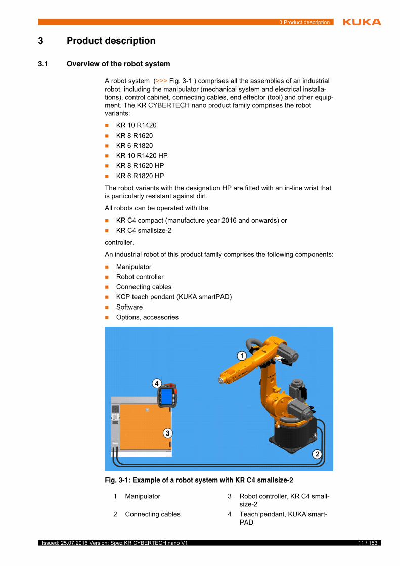
A robot system (>>> Fig. 3-1 ) comprises all the assemblies of an industrial robot, including the manipulator (mechanical system and electrical installa-tions), control cabinet, connecting cables, end effector (tool) and other equip-ment. The KR CYBERTECH nano product family comprises the robot variants:
� KR 10 R1420� KR 8 R1620� KR 6 R1820� KR 10 R1420 HP� KR 8 R1620 HP� KR 6 R1820 HP
The robot variants with the designation HP are fitted with an in-line wrist that is particularly resistant against dirt.
All robots can be operated with the
� KR C4 compact (manufacture year 2016 and onwards) or� KR C4 smallsize-2
controller.
An industrial robot of this product family comprises the following components:
� Manipulator� Robot controller� Connecting cables� KCP teach pendant (KUKA smartPAD)� Software� Options, accessories
t
s
Fig. 3-1: Example of a robot system with KR C4 smallsize-2
1 Manipulator 3 Robot controller, KR C4 small-size-2
2 Connecting cables 4 Teach pendant, KUKA smart-PAD
12 / 153 Issued: 25.07.2016 Version: Spez KR CYBERTECH nano V1
KR CYBERTECH nano
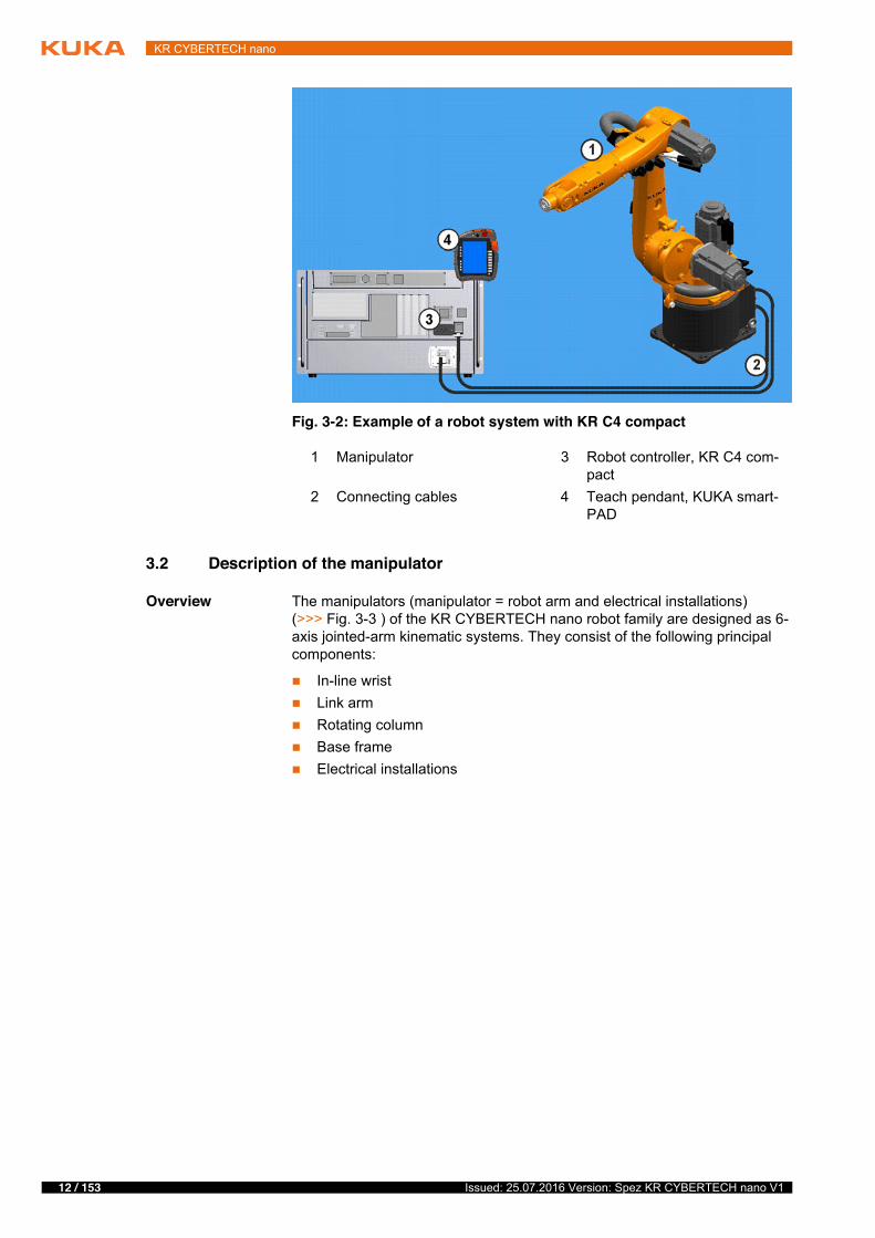
3.2 Description of the manipulator
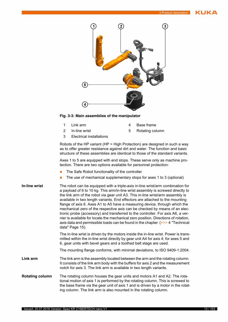
Overview The manipulators (manipulator = robot arm and electrical installations) (>>> Fig. 3-3 ) of the KR CYBERTECH nano robot family are designed as 6-axis jointed-arm kinematic systems. They consist of the following principal components:
� In-line wrist� Link arm� Rotating column� Base frame� Electrical installations
Fig. 3-2: Example of a robot system with KR C4 compact
1 Manipulator 3 Robot controller, KR C4 com-pact
2 Connecting cables 4 Teach pendant, KUKA smart-PAD
13 / 153Issued: 25.07.2016 Version: Spez KR CYBERTECH nano V1
3 Product description
Robots of the HP variant (HP = High Protection) are designed in such a way as to offer greater resistance against dirt and water. The function and basic structure of these assemblies are identical to those of the standard variants.
Axes 1 to 5 are equipped with end stops. These serve only as machine pro-tection. There are two options available for personnel protection:
� The Safe Robot functionality of the controller� The use of mechanical supplementary stops for axes 1 to 3 (optional)
In-line wrist The robot can be equipped with a triple-axis in-line wrist/arm combination for a payload of 6 to 10 kg. This arm/in-line wrist assembly is screwed directly to the link arm of the robot via gear unit A3. This in-line wrist/arm assembly is available in two length variants. End effectors are attached to the mounting flange of axis 6. Axes A1 to A5 have a measuring device, through which the mechanical zero of the respective axis can be checked by means of an elec-tronic probe (accessory) and transferred to the controller. For axis A6, a ver-nier is available for locate the mechanical zero position. Directions of rotation, axis data and permissible loads can be found in the chapter (>>> 4 "Technical data" Page 15).
The in-line wrist is driven by the motors inside the in-line wrist. Power is trans-mitted within the in-line wrist directly by gear unit A4 for axis 4; for axes 5 and 6, gear units with bevel gears and a toothed belt stage are used.
The mounting flange conforms, with minimal deviations, to ISO 9409-1:2004.
Link arm The link arm is the assembly located between the arm and the rotating column. It consists of the link arm body with the buffers for axis 2 and the measurement notch for axis 3. The link arm is available in two length variants.
Rotating column The rotating column houses the gear units and motors A1 and A2. The rota-tional motion of axis 1 is performed by the rotating column. This is screwed to the base frame via the gear unit of axis 1 and is driven by a motor in the rotat-ing column. The link arm is also mounted in the rotating column.
Fig. 3-3: Main assemblies of the manipulator
1 Link arm 4 Base frame2 In-line wrist 5 Rotating column3 Electrical installations
14 / 153 Issued: 25.07.2016 Version: Spez KR CYBERTECH nano V1
KR CYBERTECH nano
Base frame The base frame is the base of the robot. It is screwed to the mounting base. The flexible tube for the electrical installations is installed in the base frame. Also located on the rear of the base frame are the junction box for the motor and data cable and the energy supply system.
Electrical installations
The electrical installations include all the motor and control cables for the mo-tors of axes 1 to 6. The complete electrical installations consist of cable set A1 - A3 and cable set A4 - A6. For cable set A1 - A3, three variants are avail-able:
� KR C4 robot cable set A1 - A3� KR C4 robot cable set A1 - A3, Profinet � KR C4 robot cable set A1 - A3, Multibus
Cable set A4 - A6 is identical for all CYBERTECH nano robot variants.
Included in the electrical installations are the relevant cable harness and the combo box with cover. The connecting cables to the controller and, if applica-ble, the cables and hoses of the integrated energy supply system are connect-ed to the combo box.
All connections are implemented as connectors in order to enable the main axis motors to be exchanged quickly and reliably. The electrical installations also include a protective circuit. The ground conductors to the robot are con-nected to the base frame by means of ring cable lugs and setscrews.
Options The robot can be fitted and operated with various options, such as an integrat-ed energy supply system for axes 1 to 3, an energy supply system for axes 3 to 6, or working range limitation systems for axes A1, A2 and A3. The options are described in separate documentation.
15 / 153Issued: 25.07.2016 Version: Spez KR CYBERTECH nano V1
4 Technical data
4 Technical data
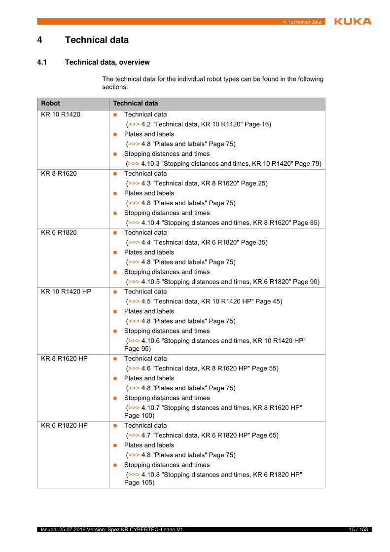
4.1 Technical data, overview
The technical data for the individual robot types can be found in the following sections:
4
T
t
Robot Technical dataKR 10 R1420 � Technical data
(>>> 4.2 "Technical data, KR 10 R1420" Page 16)� Plates and labels
(>>> 4.8 "Plates and labels" Page 75)� Stopping distances and times
(>>> 4.10.3 "Stopping distances and times, KR 10 R1420" Page 79)KR 8 R1620 � Technical data
(>>> 4.3 "Technical data, KR 8 R1620" Page 25)� Plates and labels
(>>> 4.8 "Plates and labels" Page 75)� Stopping distances and times
(>>> 4.10.4 "Stopping distances and times, KR 8 R1620" Page 85)KR 6 R1820 � Technical data
(>>> 4.4 "Technical data, KR 6 R1820" Page 35)� Plates and labels
(>>> 4.8 "Plates and labels" Page 75)� Stopping distances and times
(>>> 4.10.5 "Stopping distances and times, KR 6 R1820" Page 90)KR 10 R1420 HP � Technical data
(>>> 4.5 "Technical data, KR 10 R1420 HP" Page 45)� Plates and labels
(>>> 4.8 "Plates and labels" Page 75)� Stopping distances and times
(>>> 4.10.6 "Stopping distances and times, KR 10 R1420 HP" Page 95)
KR 8 R1620 HP � Technical data (>>> 4.6 "Technical data, KR 8 R1620 HP" Page 55)
� Plates and labels (>>> 4.8 "Plates and labels" Page 75)
� Stopping distances and times (>>> 4.10.7 "Stopping distances and times, KR 8 R1620 HP" Page 100)
KR 6 R1820 HP � Technical data (>>> 4.7 "Technical data, KR 6 R1820 HP" Page 65)
� Plates and labels (>>> 4.8 "Plates and labels" Page 75)
� Stopping distances and times (>>> 4.10.8 "Stopping distances and times, KR 6 R1820 HP" Page 105)
16 / 153 Issued: 25.07.2016 Version: Spez KR CYBERTECH nano V1
KR CYBERTECH nano
4.2 Technical data, KR 10 R1420
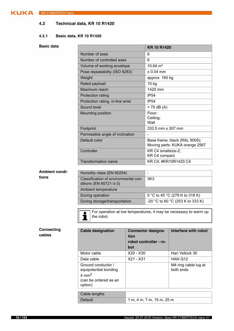
4.2.1 Basic data, KR 10 R1420
Basic data
Ambient condi-tions
Connecting cables
KR 10 R1420Number of axes 6Number of controlled axes 6Volume of working envelope 10.64 m³Pose repeatability (ISO 9283) ± 0.04 mmWeight approx. 160 kgRated payload 10 kgMaximum reach 1420 mmProtection rating IP54Protection rating, in-line wrist IP54Sound level < 75 dB (A)Mounting position Floor;
Ceiling;Wall
Footprint 333.5 mm x 307 mmPermissible angle of inclination -Default color Base frame: black (RAL 9005);
Moving parts: KUKA orange 2567Controller KR C4 smallsize-2;
KR C4 compactTransformation name KR C4: #KR10R1420 C4
Humidity class (EN 60204) -Classification of environmental con-ditions (EN 60721-3-3)
3K3
Ambient temperatureDuring operation 5 °C to 45 °C (278 K to 318 K)During storage/transportation -20 °C to 60 °C (253 K to 333 K)
For operation at low temperatures, it may be necessary to warm up the robot.
Cable designation Connector designa-tionrobot controller - ro-bot
Interface with robot
Motor cable X20 - X30 Han Yellock 30Data cable X21 - X31 HAN Q12Ground conductor / equipotential bonding4 mm2
(can be ordered as an option)
M4 ring cable lug at both ends
Cable lengthsDefault 1 m, 4 m, 7 m, 15 m, 25 m
17 / 153Issued: 25.07.2016 Version: Spez KR CYBERTECH nano V1
4 Technical data
For detailed specifications of the connecting cables, see “Description of the connecting cables”.
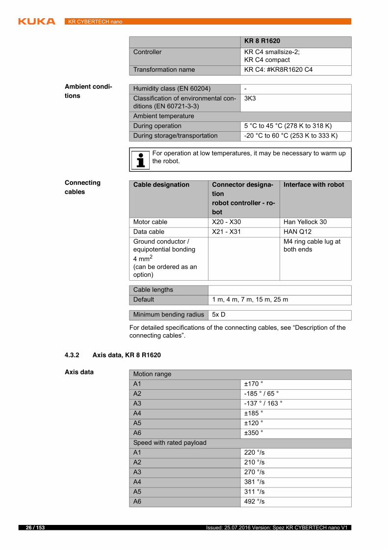
4.2.2 Axis data, KR 10 R1420
Axis data
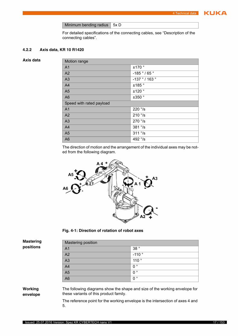
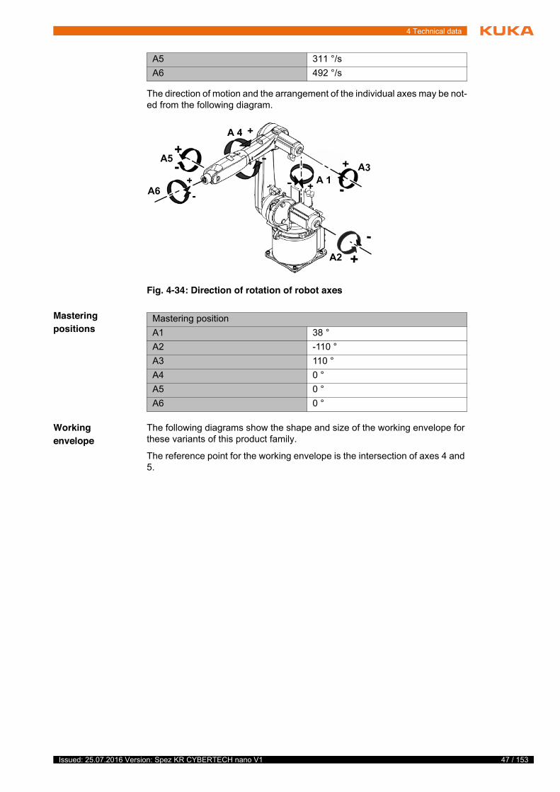
The direction of motion and the arrangement of the individual axes may be not-ed from the following diagram.
Mastering positions
Working envelope
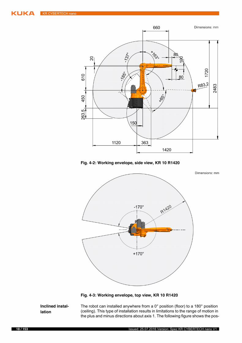
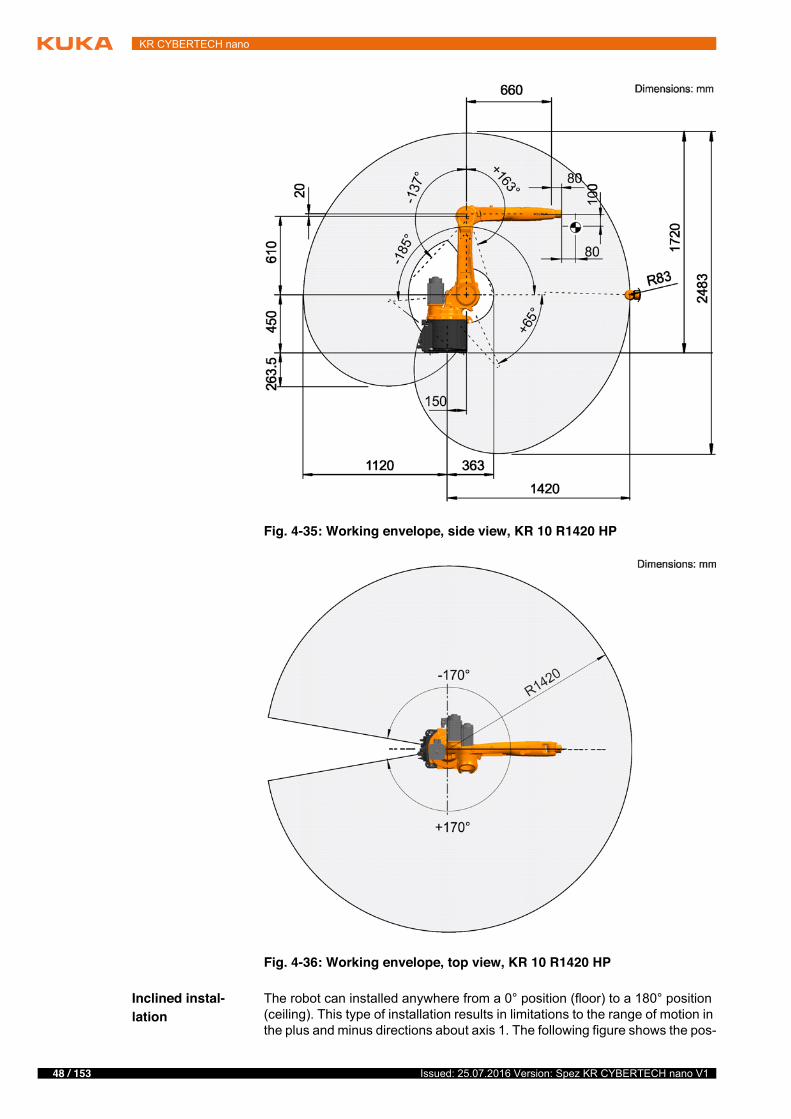
The following diagrams show the shape and size of the working envelope for these variants of this product family.
The reference point for the working envelope is the intersection of axes 4 and 5.
Minimum bending radius 5x D
Motion rangeA1 ±170 °A2 -185 ° / 65 °A3 -137 ° / 163 °A4 ±185 °A5 ±120 °A6 ±350 °Speed with rated payloadA1 220 °/sA2 210 °/sA3 270 °/sA4 381 °/sA5 311 °/sA6 492 °/s
Fig. 4-1: Direction of rotation of robot axes
Mastering positionA1 38 °A2 -110 °A3 110 °A4 0 °A5 0 °A6 0 °
18 / 153 Issued: 25.07.2016 Version: Spez KR CYBERTECH nano V1
KR CYBERTECH nano
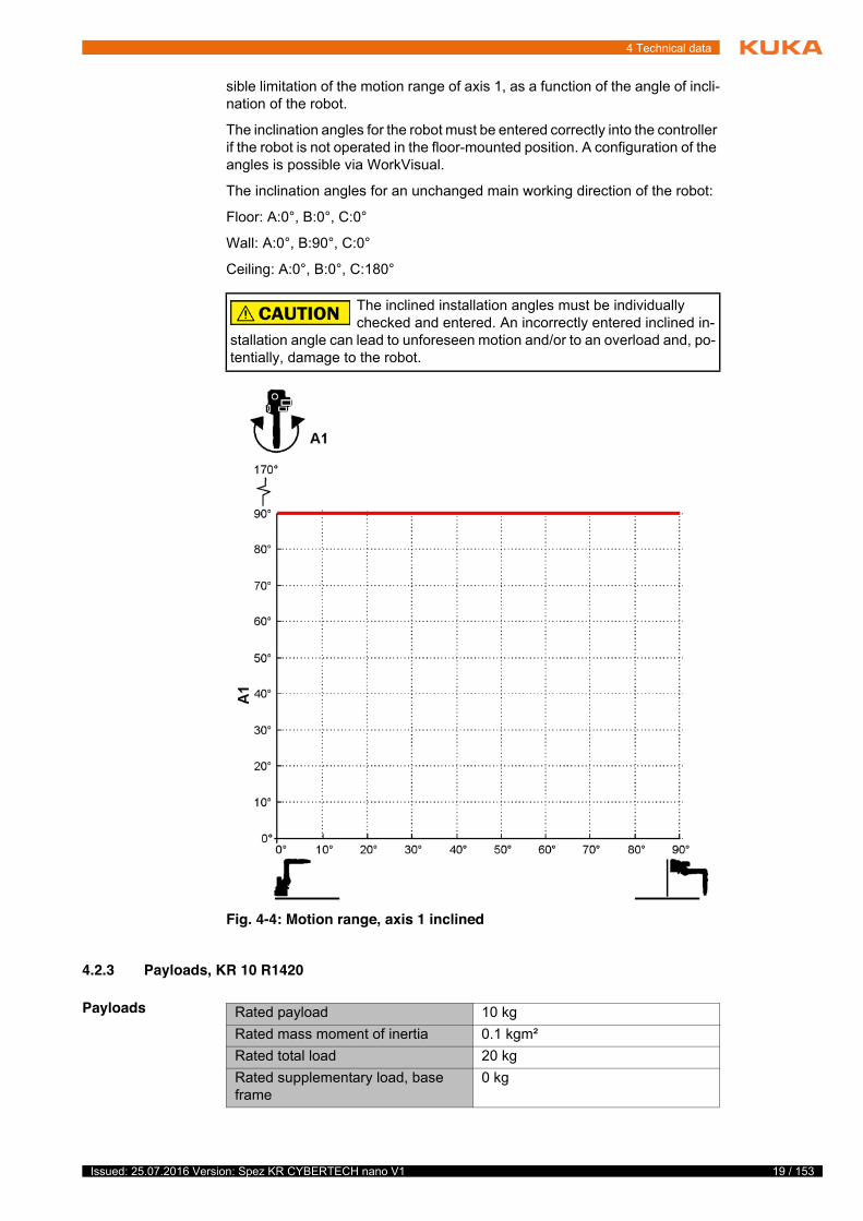
Inclined instal-lation
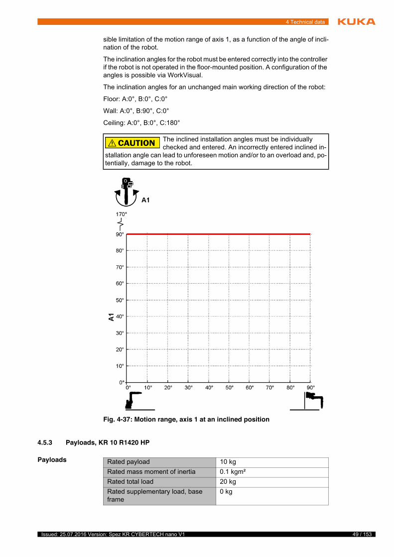
The robot can installed anywhere from a 0° position (floor) to a 180° position (ceiling). This type of installation results in limitations to the range of motion in the plus and minus directions about axis 1. The following figure shows the pos-
Fig. 4-2: Working envelope, side view, KR 10 R1420
Fig. 4-3: Working envelope, top view, KR 10 R1420
19 / 153Issued: 25.07.2016 Version: Spez KR CYBERTECH nano V1
4 Technical data
sible limitation of the motion range of axis 1, as a function of the angle of incli-nation of the robot.
The inclination angles for the robot must be entered correctly into the controller if the robot is not operated in the floor-mounted position. A configuration of the angles is possible via WorkVisual.
The inclination angles for an unchanged main working direction of the robot:
Floor: A:0°, B:0°, C:0°
Wall: A:0°, B:90°, C:0°
Ceiling: A:0°, B:0°, C:180°
4.2.3 Payloads, KR 10 R1420
Payloads
The inclined installation angles must be individually checked and entered. An incorrectly entered inclined in-
stallation angle can lead to unforeseen motion and/or to an overload and, po-tentially, damage to the robot.
Fig. 4-4: Motion range, axis 1 inclined
Rated payload 10 kgRated mass moment of inertia 0.1 kgm²Rated total load 20 kgRated supplementary load, base frame
0 kg
20 / 153 Issued: 25.07.2016 Version: Spez KR CYBERTECH nano V1
KR CYBERTECH nano
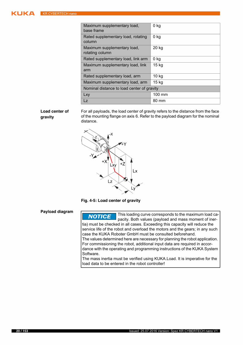
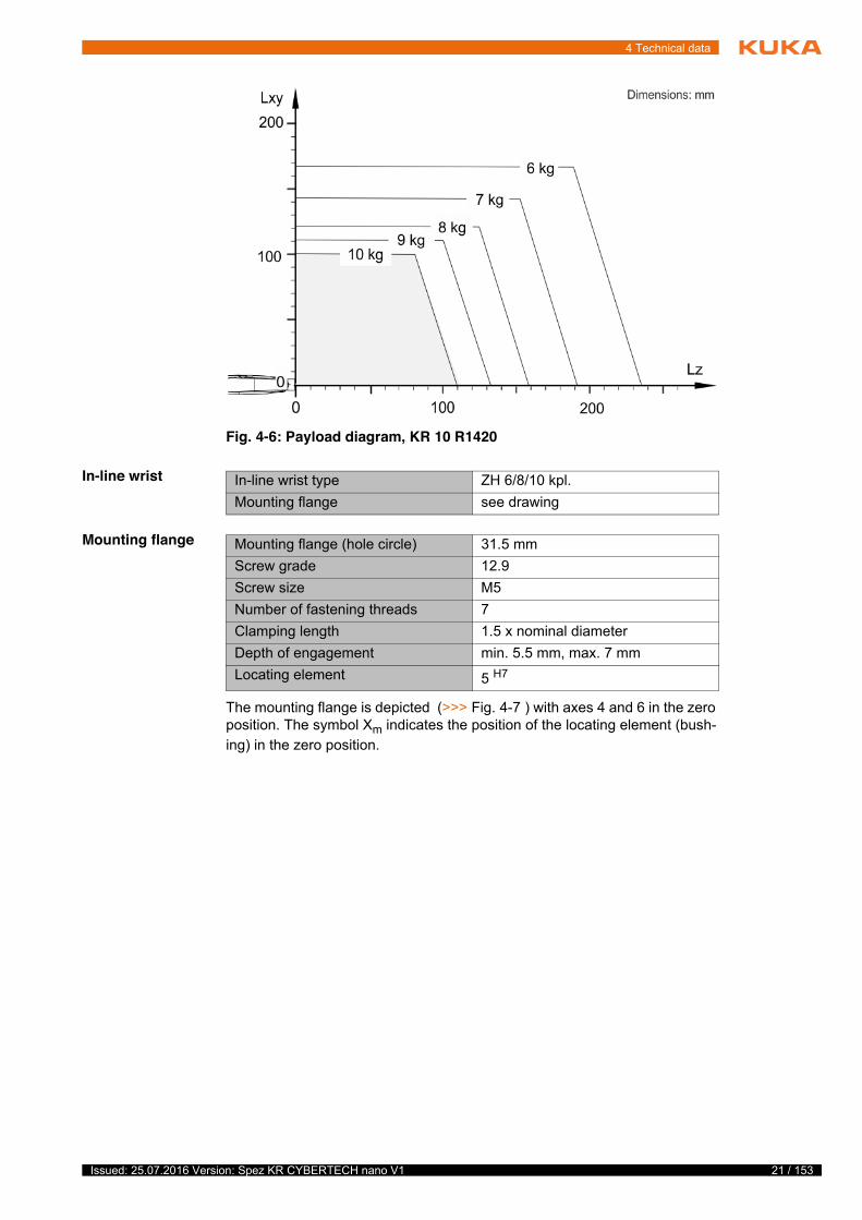
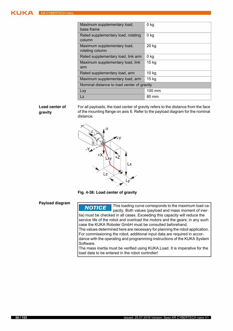
Load center of gravity
For all payloads, the load center of gravity refers to the distance from the face of the mounting flange on axis 6. Refer to the payload diagram for the nominal distance.
Payload diagram
Maximum supplementary load, base frame
0 kg
Rated supplementary load, rotating column
0 kg
Maximum supplementary load, rotating column
20 kg
Rated supplementary load, link arm 0 kgMaximum supplementary load, link arm
15 kg
Rated supplementary load, arm 10 kgMaximum supplementary load, arm 15 kgNominal distance to load center of gravityLxy 100 mmLz 80 mm
Fig. 4-5: Load center of gravity
This loading curve corresponds to the maximum load ca-pacity. Both values (payload and mass moment of iner-
tia) must be checked in all cases. Exceeding this capacity will reduce the service life of the robot and overload the motors and the gears; in any such case the KUKA Roboter GmbH must be consulted beforehand.The values determined here are necessary for planning the robot application. For commissioning the robot, additional input data are required in accor-dance with the operating and programming instructions of the KUKA System Software.The mass inertia must be verified using KUKA.Load. It is imperative for the load data to be entered in the robot controller!
21 / 153Issued: 25.07.2016 Version: Spez KR CYBERTECH nano V1
4 Technical data
In-line wrist
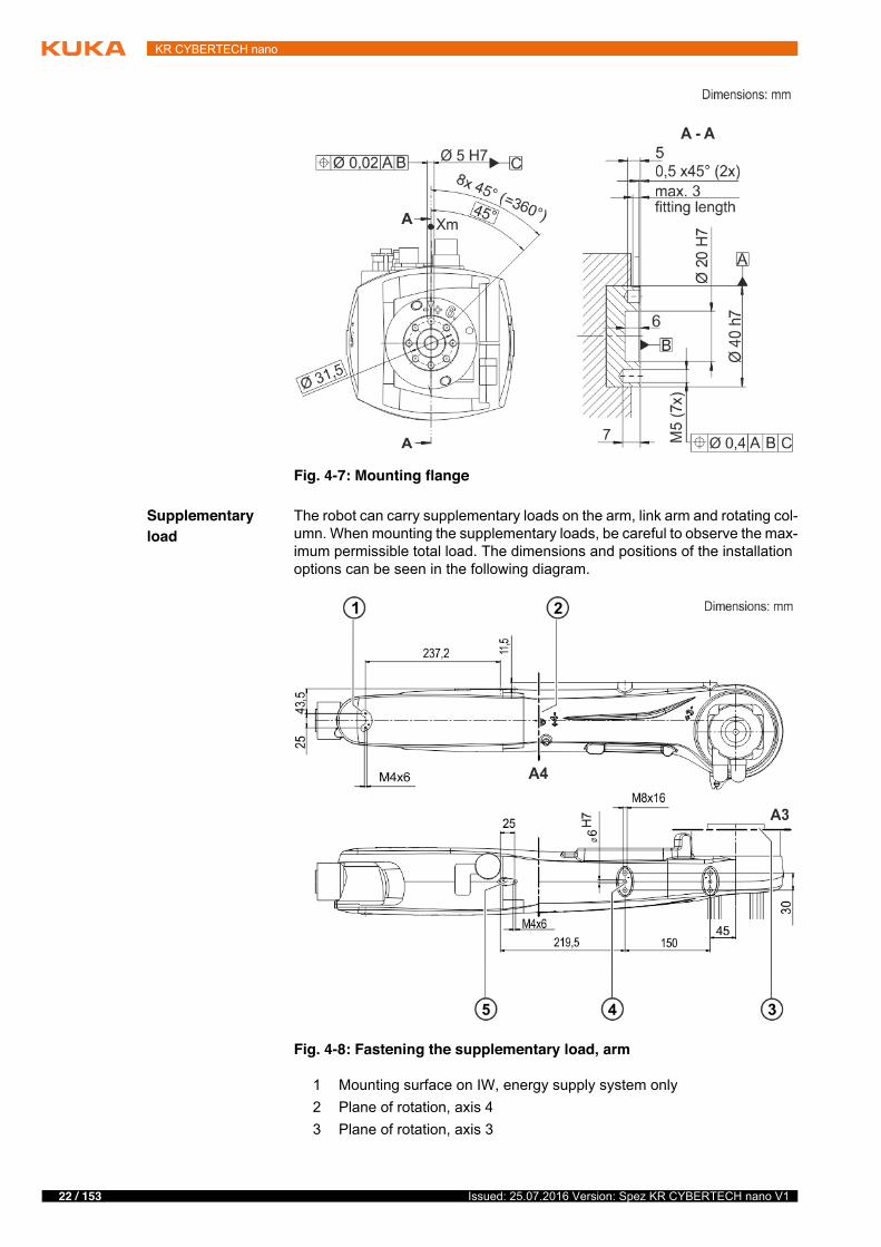
Mounting flange
The mounting flange is depicted (>>> Fig. 4-7 ) with axes 4 and 6 in the zero position. The symbol Xm indicates the position of the locating element (bush-ing) in the zero position.
Fig. 4-6: Payload diagram, KR 10 R1420
In-line wrist type ZH 6/8/10 kpl.Mounting flange see drawing
Mounting flange (hole circle) 31.5 mmScrew grade 12.9Screw size M5Number of fastening threads 7Clamping length 1.5 x nominal diameterDepth of engagement min. 5.5 mm, max. 7 mmLocating element 5 H7
22 / 153 Issued: 25.07.2016 Version: Spez KR CYBERTECH nano V1
KR CYBERTECH nano
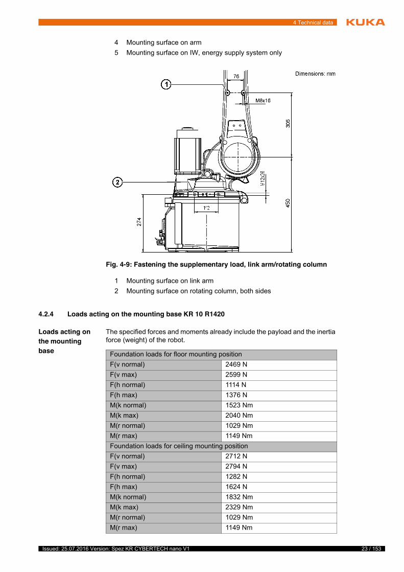
Supplementary load
The robot can carry supplementary loads on the arm, link arm and rotating col-umn. When mounting the supplementary loads, be careful to observe the max-imum permissible total load. The dimensions and positions of the installation options can be seen in the following diagram.
Fig. 4-7: Mounting flange
Fig. 4-8: Fastening the supplementary load, arm
1 Mounting surface on IW, energy supply system only2 Plane of rotation, axis 43 Plane of rotation, axis 3
23 / 153Issued: 25.07.2016 Version: Spez KR CYBERTECH nano V1
4 Technical data
4.2.4 Loads acting on the mounting base KR 10 R1420
Loads acting on the mounting base
The specified forces and moments already include the payload and the inertia force (weight) of the robot.
4 Mounting surface on arm5 Mounting surface on IW, energy supply system only
Fig. 4-9: Fastening the supplementary load, link arm/rotating column
1 Mounting surface on link arm2 Mounting surface on rotating column, both sides
Foundation loads for floor mounting positionF(v normal) 2469 NF(v max) 2599 NF(h normal) 1114 NF(h max) 1376 NM(k normal) 1523 NmM(k max) 2040 NmM(r normal) 1029 NmM(r max) 1149 NmFoundation loads for ceiling mounting positionF(v normal) 2712 NF(v max) 2794 NF(h normal) 1282 NF(h max) 1624 NM(k normal) 1832 NmM(k max) 2329 NmM(r normal) 1029 NmM(r max) 1149 Nm

24 / 153 Issued: 25.07.2016 Version: Spez KR CYBERTECH nano V1
KR CYBERTECH nano
Vertical force F(v), horizontal force F(h), tilting torque M(k), torque about axis 1 M(r)
4.2.5 Transport dimensions, KR 10 R1420
The transport dimensions for the robots can be noted from the following dia-grams (>>> Fig. 4-11 ). The position of the center of gravity and the weight vary according to the specific configuration. The specified dimensions refer to
Foundation loads for wall mounting positionF(v normal) 800 NF(v max) 1000 NF(h normal) 2748 NF(h max) 2987 NM(k normal) 2562 NmM(k max) 2701 NmM(r normal) 947 NmM(r max) 1126 Nm
Fig. 4-10: Foundation loads
Normal loads and maximum loads for the foundations are specified in the table.
The maximum loads must be referred to when dimensioning the foundations and must be adhered to for safety reasons. Failure to observe this can result in personal injury and damage to property.The normal loads are average expected foundation loads. The actual loads are dependent on the program and on the robot loads and may therefore be greater or less than the normal loads.The supplementary loads (A1 and A2) are not taken into consideration in the calculation of the mounting base load. These supplementary loads must be taken into consideration for Fv.

25 / 153Issued: 25.07.2016 Version: Spez KR CYBERTECH nano V1
4 Technical data
the robot without equipment. The following diagram shows the dimensions of the robot when it stands on the floor without wooden transport blocks.
4.3 Technical data, KR 8 R1620
4.3.1 Basic data, KR 8 R1620
Basic data
Fig. 4-11: Transport dimensions
1 Robot 3 Fork slots2 Center of gravity
KR 8 R1620Number of axes 6Number of controlled axes 6Volume of working envelope 15.93 m³Pose repeatability (ISO 9283) ± 0.04 mmWeight approx. 165 kgRated payload 8 kgMaximum reach 1620 mmProtection rating IP54Protection rating, in-line wrist IP54Sound level < 75 dB (A)Mounting position Floor;
Ceiling;Wall
Footprint 333.5 mm x 307 mmPermissible angle of inclination -Default color Base frame: black (RAL 9005);
Moving parts: KUKA orange 2567
26 / 153 Issued: 25.07.2016 Version: Spez KR CYBERTECH nano V1
KR CYBERTECH nano
Ambient condi-tions
Connecting cables
For detailed specifications of the connecting cables, see “Description of the connecting cables”.
4.3.2 Axis data, KR 8 R1620
Axis data
Controller KR C4 smallsize-2;KR C4 compact
Transformation name KR C4: #KR8R1620 C4
KR 8 R1620
Humidity class (EN 60204) -Classification of environmental con-ditions (EN 60721-3-3)
3K3
Ambient temperatureDuring operation 5 °C to 45 °C (278 K to 318 K)During storage/transportation -20 °C to 60 °C (253 K to 333 K)
For operation at low temperatures, it may be necessary to warm up the robot.
Cable designation Connector designa-tionrobot controller - ro-bot
Interface with robot
Motor cable X20 - X30 Han Yellock 30Data cable X21 - X31 HAN Q12Ground conductor / equipotential bonding4 mm2
(can be ordered as an option)
M4 ring cable lug at both ends
Cable lengthsDefault 1 m, 4 m, 7 m, 15 m, 25 m
Minimum bending radius 5x D
Motion rangeA1 ±170 °A2 -185 ° / 65 °A3 -137 ° / 163 °A4 ±185 °A5 ±120 °A6 ±350 °Speed with rated payloadA1 220 °/sA2 210 °/sA3 270 °/sA4 381 °/sA5 311 °/sA6 492 °/s

27 / 153Issued: 25.07.2016 Version: Spez KR CYBERTECH nano V1
4 Technical data
The direction of motion and the arrangement of the individual axes may be not-ed from the following diagram.
Mastering positions
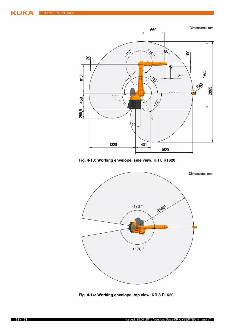
Working envelope
The following diagrams show the shape and size of the working envelope for these variants of this product family.
The reference point for the working envelope is the intersection of axes 4 and 5.
Fig. 4-12: Direction of rotation of robot axes
Mastering positionA1 38 °A2 -110 °A3 110 °A4 0 °A5 0 °A6 0 °
28 / 153 Issued: 25.07.2016 Version: Spez KR CYBERTECH nano V1
KR CYBERTECH nano
Fig. 4-13: Working envelope, side view, KR 8 R1620
Fig. 4-14: Working envelope, top view, KR 8 R1620
29 / 153Issued: 25.07.2016 Version: Spez KR CYBERTECH nano V1
4 Technical data
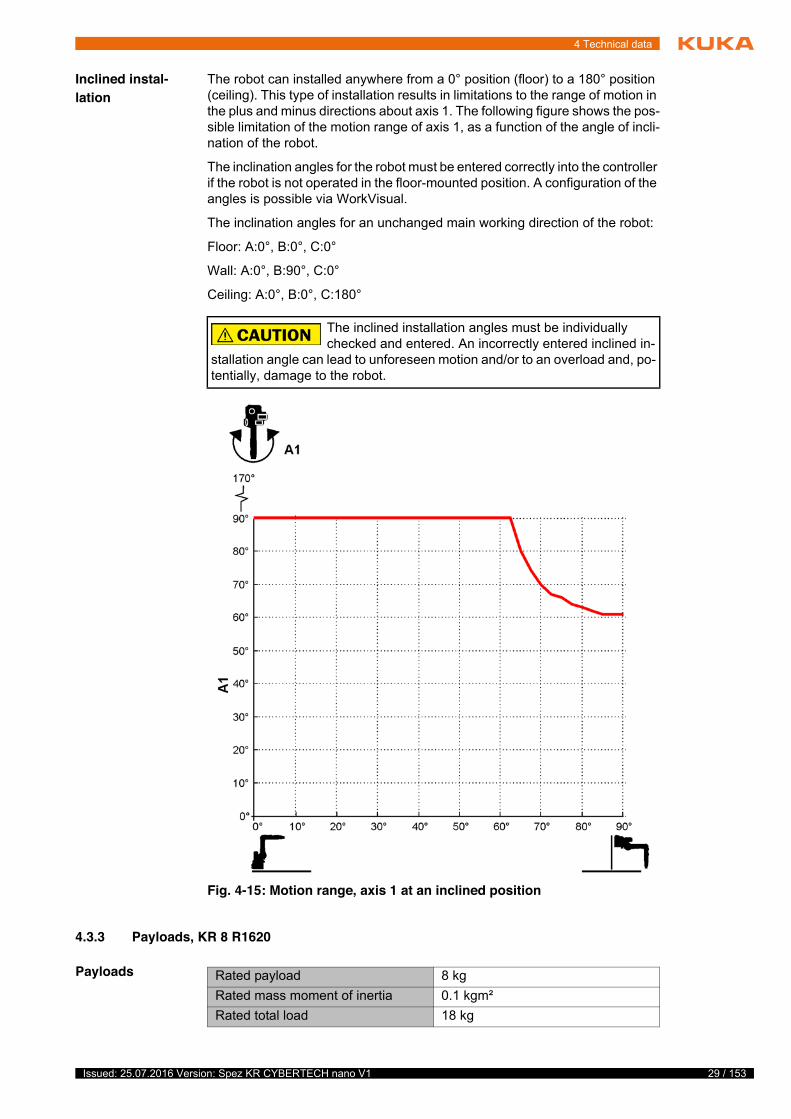
Inclined instal-lation
The robot can installed anywhere from a 0° position (floor) to a 180° position (ceiling). This type of installation results in limitations to the range of motion in the plus and minus directions about axis 1. The following figure shows the pos-sible limitation of the motion range of axis 1, as a function of the angle of incli-nation of the robot.
The inclination angles for the robot must be entered correctly into the controller if the robot is not operated in the floor-mounted position. A configuration of the angles is possible via WorkVisual.
The inclination angles for an unchanged main working direction of the robot:
Floor: A:0°, B:0°, C:0°
Wall: A:0°, B:90°, C:0°
Ceiling: A:0°, B:0°, C:180°
4.3.3 Payloads, KR 8 R1620
Payloads
The inclined installation angles must be individually checked and entered. An incorrectly entered inclined in-
stallation angle can lead to unforeseen motion and/or to an overload and, po-tentially, damage to the robot.
Fig. 4-15: Motion range, axis 1 at an inclined position
Rated payload 8 kgRated mass moment of inertia 0.1 kgm²Rated total load 18 kg

30 / 153 Issued: 25.07.2016 Version: Spez KR CYBERTECH nano V1
KR CYBERTECH nano
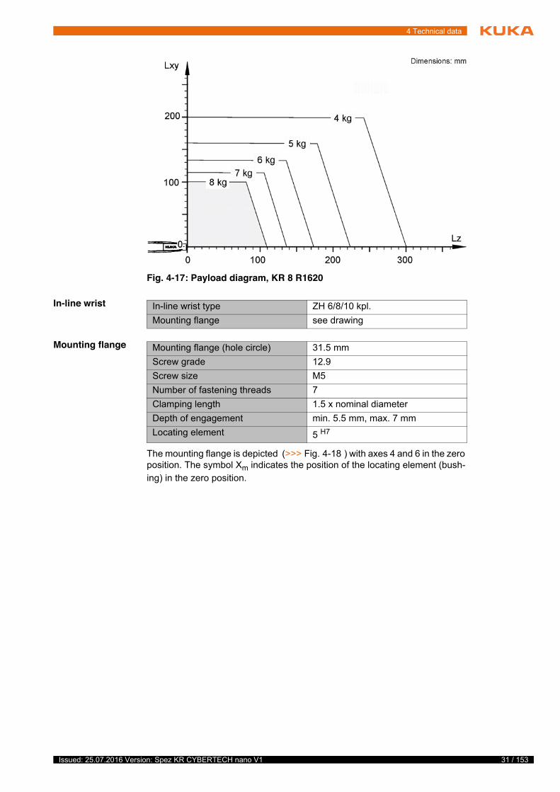
Load center of gravity
For all payloads, the load center of gravity refers to the distance from the face of the mounting flange on axis 6. Refer to the payload diagram for the nominal distance.
Payload diagram
Rated supplementary load, base frame
0 kg
Maximum supplementary load, base frame
0 kg
Rated supplementary load, rotating column
0 kg
Maximum supplementary load, rotating column
20 kg
Rated supplementary load, link arm 0 kgMaximum supplementary load, link arm
15 kg
Rated supplementary load, arm 10 kgMaximum supplementary load, arm 15 kgNominal distance to load center of gravityLxy 100 mmLz 80 mm
Fig. 4-16: Load center of gravity
This loading curve corresponds to the maximum load ca-pacity. Both values (payload and mass moment of iner-
tia) must be checked in all cases. Exceeding this capacity will reduce the service life of the robot and overload the motors and the gears; in any such case the KUKA Roboter GmbH must be consulted beforehand.The values determined here are necessary for planning the robot application. For commissioning the robot, additional input data are required in accor-dance with the operating and programming instructions of the KUKA System Software.The mass inertia must be verified using KUKA.Load. It is imperative for the load data to be entered in the robot controller!
31 / 153Issued: 25.07.2016 Version: Spez KR CYBERTECH nano V1
4 Technical data
In-line wrist
Mounting flange
The mounting flange is depicted (>>> Fig. 4-18 ) with axes 4 and 6 in the zero position. The symbol Xm indicates the position of the locating element (bush-ing) in the zero position.
Fig. 4-17: Payload diagram, KR 8 R1620
In-line wrist type ZH 6/8/10 kpl.Mounting flange see drawing
Mounting flange (hole circle) 31.5 mmScrew grade 12.9Screw size M5Number of fastening threads 7Clamping length 1.5 x nominal diameterDepth of engagement min. 5.5 mm, max. 7 mmLocating element 5 H7

32 / 153 Issued: 25.07.2016 Version: Spez KR CYBERTECH nano V1
KR CYBERTECH nano
Supplementary load
The robot can carry supplementary loads on the arm, link arm and rotating col-umn. When mounting the supplementary loads, be careful to observe the max-imum permissible total load. The dimensions and positions of the installation options can be seen in the following diagram.
Fig. 4-18: Mounting flange
Fig. 4-19: Fastening the supplementary load on the arm
1 Mounting surface on IW, energy supply system only2 Plane of rotation, axis 43 Plane of rotation, axis 3

33 / 153Issued: 25.07.2016 Version: Spez KR CYBERTECH nano V1
4 Technical data
4.3.4 Loads acting on the mounting base KR 8 R1620
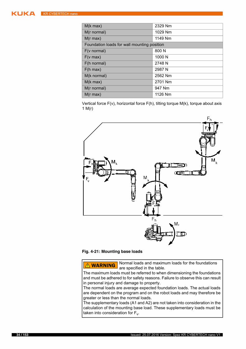
Loads acting on the mounting base
The specified forces and moments already include the payload and the inertia force (weight) of the robot.
4 Mounting surface on arm5 Mounting surface on IW, energy supply system only
Fig. 4-20: Fastening the supplementary load on the link arm/rotating col-umn
1 Mounting surface on link arm2 Mounting surface on rotating column, both sides
Foundation loads for floor mounting positionF(v normal) 2469 NF(v max) 2599 NF(h normal) 1114 NF(h max) 1376 NM(k normal) 1523 NmM(k max) 2040 NmM(r normal) 1029 NmM(r max) 1149 NmFoundation loads for ceiling mounting positionF(v normal) 2712 NF(v max) 2794 NF(h normal) 1282 NF(h max) 1624 NM(k normal) 1832 Nm
34 / 153 Issued: 25.07.2016 Version: Spez KR CYBERTECH nano V1
KR CYBERTECH nano
Vertical force F(v), horizontal force F(h), tilting torque M(k), torque about axis 1 M(r)
M(k max) 2329 NmM(r normal) 1029 NmM(r max) 1149 NmFoundation loads for wall mounting positionF(v normal) 800 NF(v max) 1000 NF(h normal) 2748 NF(h max) 2987 NM(k normal) 2562 NmM(k max) 2701 NmM(r normal) 947 NmM(r max) 1126 Nm
Fig. 4-21: Mounting base loads
Normal loads and maximum loads for the foundations are specified in the table.
The maximum loads must be referred to when dimensioning the foundations and must be adhered to for safety reasons. Failure to observe this can result in personal injury and damage to property.The normal loads are average expected foundation loads. The actual loads are dependent on the program and on the robot loads and may therefore be greater or less than the normal loads.The supplementary loads (A1 and A2) are not taken into consideration in the calculation of the mounting base load. These supplementary loads must be taken into consideration for Fv.
35 / 153Issued: 25.07.2016 Version: Spez KR CYBERTECH nano V1
4 Technical data
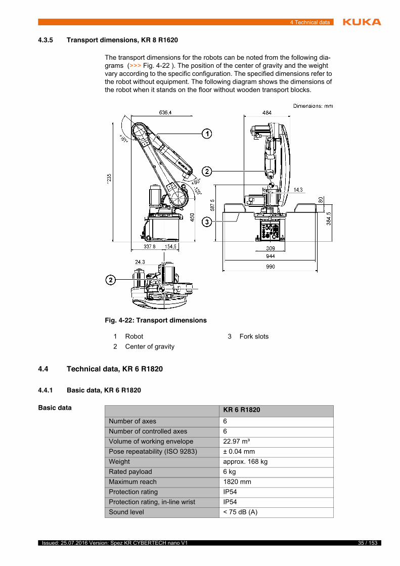
4.3.5 Transport dimensions, KR 8 R1620
The transport dimensions for the robots can be noted from the following dia-grams (>>> Fig. 4-22 ). The position of the center of gravity and the weight vary according to the specific configuration. The specified dimensions refer to the robot without equipment. The following diagram shows the dimensions of the robot when it stands on the floor without wooden transport blocks.
4.4 Technical data, KR 6 R1820
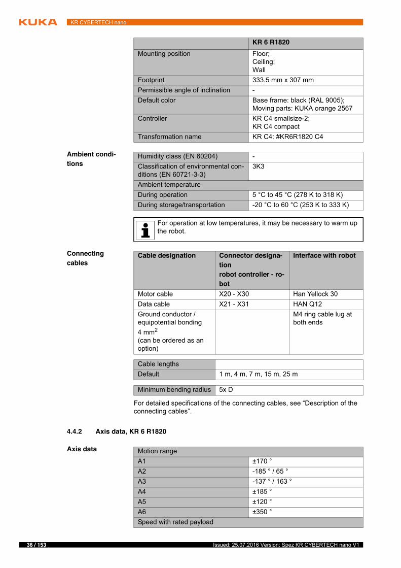
4.4.1 Basic data, KR 6 R1820
Basic data
Fig. 4-22: Transport dimensions
1 Robot 3 Fork slots2 Center of gravity
KR 6 R1820Number of axes 6Number of controlled axes 6Volume of working envelope 22.97 m³Pose repeatability (ISO 9283) ± 0.04 mmWeight approx. 168 kgRated payload 6 kgMaximum reach 1820 mmProtection rating IP54Protection rating, in-line wrist IP54Sound level < 75 dB (A)
36 / 153 Issued: 25.07.2016 Version: Spez KR CYBERTECH nano V1
KR CYBERTECH nano
Ambient condi-tions
Connecting cables
For detailed specifications of the connecting cables, see “Description of the connecting cables”.
4.4.2 Axis data, KR 6 R1820
Axis data
Mounting position Floor;Ceiling;Wall
Footprint 333.5 mm x 307 mmPermissible angle of inclination -Default color Base frame: black (RAL 9005);
Moving parts: KUKA orange 2567Controller KR C4 smallsize-2;
KR C4 compactTransformation name KR C4: #KR6R1820 C4
KR 6 R1820
Humidity class (EN 60204) -Classification of environmental con-ditions (EN 60721-3-3)
3K3
Ambient temperatureDuring operation 5 °C to 45 °C (278 K to 318 K)During storage/transportation -20 °C to 60 °C (253 K to 333 K)
For operation at low temperatures, it may be necessary to warm up the robot.
Cable designation Connector designa-tionrobot controller - ro-bot
Interface with robot
Motor cable X20 - X30 Han Yellock 30Data cable X21 - X31 HAN Q12Ground conductor / equipotential bonding4 mm2
(can be ordered as an option)
M4 ring cable lug at both ends
Cable lengthsDefault 1 m, 4 m, 7 m, 15 m, 25 m
Minimum bending radius 5x D
Motion rangeA1 ±170 °A2 -185 ° / 65 °A3 -137 ° / 163 °A4 ±185 °A5 ±120 °A6 ±350 °Speed with rated payload
37 / 153Issued: 25.07.2016 Version: Spez KR CYBERTECH nano V1
4 Technical data
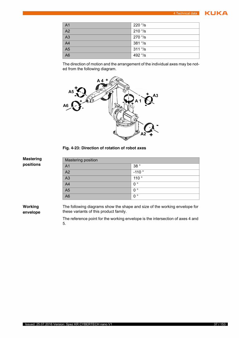
The direction of motion and the arrangement of the individual axes may be not-ed from the following diagram.
Mastering positions
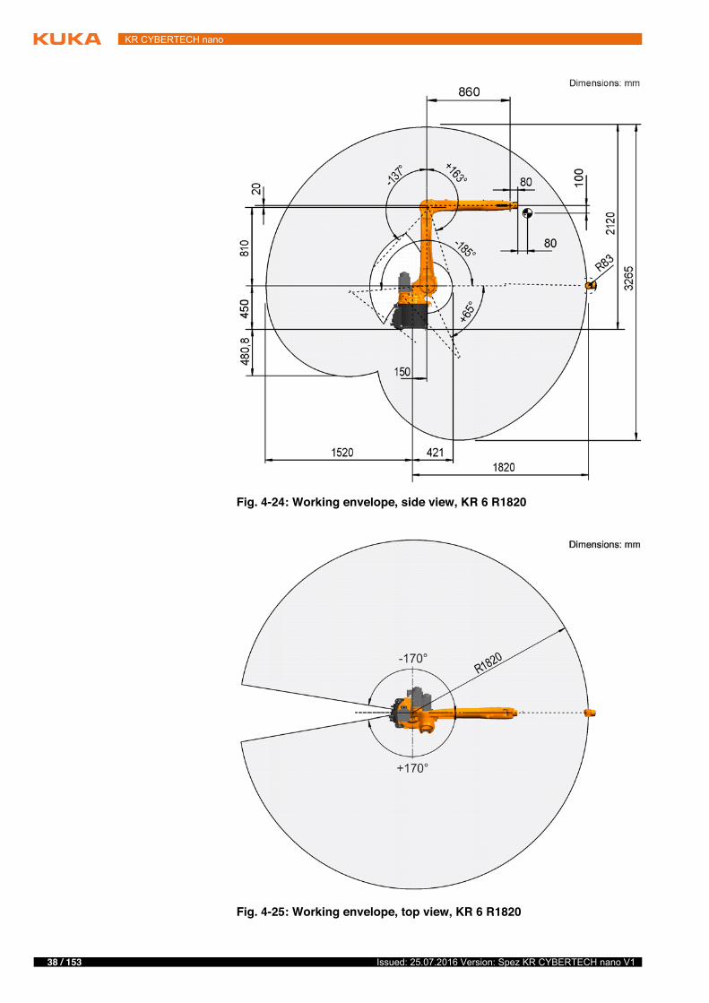
Working envelope
The following diagrams show the shape and size of the working envelope for these variants of this product family.
The reference point for the working envelope is the intersection of axes 4 and 5.
A1 220 °/sA2 210 °/sA3 270 °/sA4 381 °/sA5 311 °/sA6 492 °/s
Fig. 4-23: Direction of rotation of robot axes
Mastering positionA1 38 °A2 -110 °A3 110 °A4 0 °A5 0 °A6 0 °
38 / 153 Issued: 25.07.2016 Version: Spez KR CYBERTECH nano V1
KR CYBERTECH nano
Fig. 4-24: Working envelope, side view, KR 6 R1820
Fig. 4-25: Working envelope, top view, KR 6 R1820
39 / 153Issued: 25.07.2016 Version: Spez KR CYBERTECH nano V1
4 Technical data
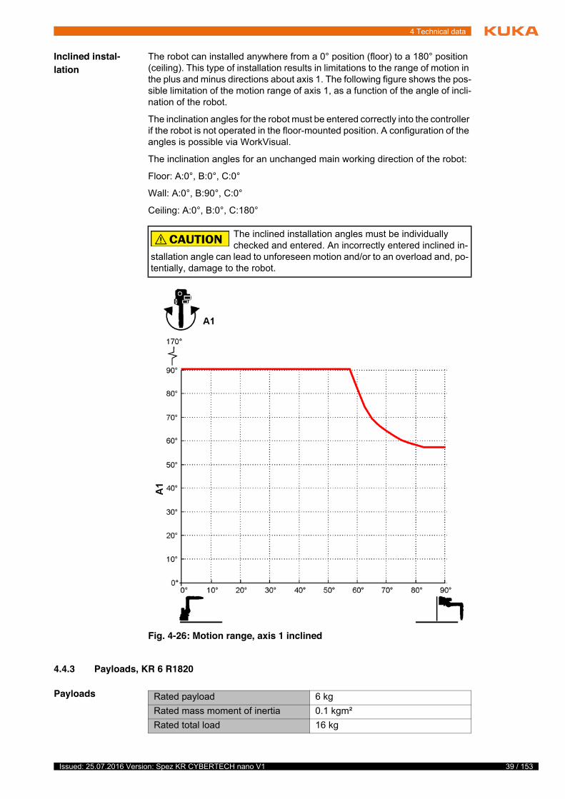
Inclined instal-lation
The robot can installed anywhere from a 0° position (floor) to a 180° position (ceiling). This type of installation results in limitations to the range of motion in the plus and minus directions about axis 1. The following figure shows the pos-sible limitation of the motion range of axis 1, as a function of the angle of incli-nation of the robot.
The inclination angles for the robot must be entered correctly into the controller if the robot is not operated in the floor-mounted position. A configuration of the angles is possible via WorkVisual.
The inclination angles for an unchanged main working direction of the robot:
Floor: A:0°, B:0°, C:0°
Wall: A:0°, B:90°, C:0°
Ceiling: A:0°, B:0°, C:180°
4.4.3 Payloads, KR 6 R1820
Payloads
The inclined installation angles must be individually checked and entered. An incorrectly entered inclined in-
stallation angle can lead to unforeseen motion and/or to an overload and, po-tentially, damage to the robot.
Fig. 4-26: Motion range, axis 1 inclined
Rated payload 6 kgRated mass moment of inertia 0.1 kgm²Rated total load 16 kg
40 / 153 Issued: 25.07.2016 Version: Spez KR CYBERTECH nano V1
KR CYBERTECH nano
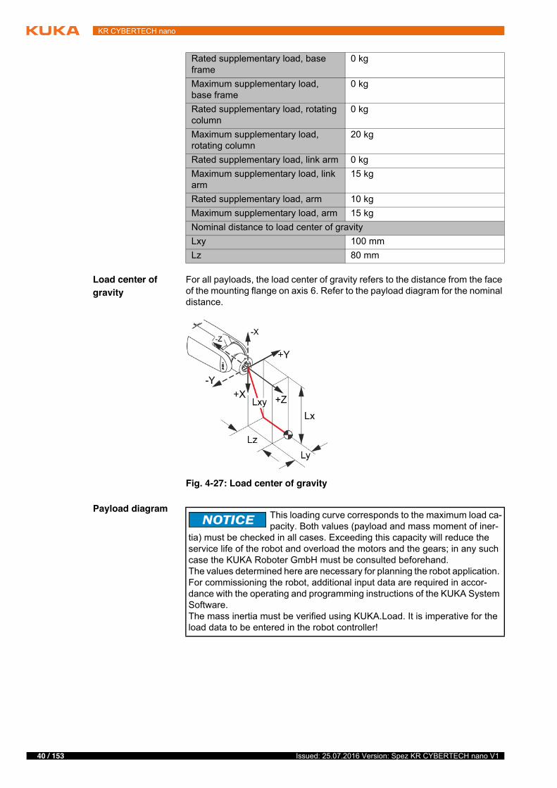
Load center of gravity
For all payloads, the load center of gravity refers to the distance from the face of the mounting flange on axis 6. Refer to the payload diagram for the nominal distance.
Payload diagram
Rated supplementary load, base frame
0 kg
Maximum supplementary load, base frame
0 kg
Rated supplementary load, rotating column
0 kg
Maximum supplementary load, rotating column
20 kg
Rated supplementary load, link arm 0 kgMaximum supplementary load, link arm
15 kg
Rated supplementary load, arm 10 kgMaximum supplementary load, arm 15 kgNominal distance to load center of gravityLxy 100 mmLz 80 mm
Fig. 4-27: Load center of gravity
This loading curve corresponds to the maximum load ca-pacity. Both values (payload and mass moment of iner-
tia) must be checked in all cases. Exceeding this capacity will reduce the service life of the robot and overload the motors and the gears; in any such case the KUKA Roboter GmbH must be consulted beforehand.The values determined here are necessary for planning the robot application. For commissioning the robot, additional input data are required in accor-dance with the operating and programming instructions of the KUKA System Software.The mass inertia must be verified using KUKA.Load. It is imperative for the load data to be entered in the robot controller!

41 / 153Issued: 25.07.2016 Version: Spez KR CYBERTECH nano V1
4 Technical data
In-line wrist
Mounting flange
The mounting flange is depicted (>>> Fig. 4-29 ) with axes 4 and 6 in the zero position. The symbol Xm indicates the position of the locating element (bush-ing) in the zero position.
Fig. 4-28: Payload diagram, KR 6 R1820
In-line wrist type ZH 6/8/10 kpl.Mounting flange see drawing
Mounting flange (hole circle) 31.5 mmScrew grade 12.9Screw size M5Number of fastening threads 7Clamping length 1.5 x nominal diameterDepth of engagement min. 5.5 mm, max. 7 mmLocating element 5 H7
Fig. 4-29: Mounting flange

42 / 153 Issued: 25.07.2016 Version: Spez KR CYBERTECH nano V1
KR CYBERTECH nano
Supplementary load
The robot can carry supplementary loads on the arm, link arm and rotating col-umn. When mounting the supplementary loads, be careful to observe the max-imum permissible total load. The dimensions and positions of the installation options can be seen in the following diagram.
Fig. 4-30: Fastening the supplementary load on the arm
1 Mounting surface on IW, energy supply system only2 Plane of rotation, axis 43 Plane of rotation, axis 34 Mounting surface on arm5 Mounting surface on IW, energy supply system only

43 / 153Issued: 25.07.2016 Version: Spez KR CYBERTECH nano V1
4 Technical data
4.4.4 Loads acting on the mounting base KR 6 R1820
Loads acting on the mounting base
The specified forces and moments already include the payload and the inertia force (weight) of the robot.
Fig. 4-31: Fastening the supplementary load on the link arm/rotating col-umn
1 Mounting surface on link arm2 Mounting surface on rotating column, both sides
Foundation loads for floor mounting positionF(v normal) 2469 NF(v max) 2599 NF(h normal) 1114 NF(h max) 1376 NM(k normal) 1523 NmM(k max) 2040 NmM(r normal) 1029 NmM(r max) 1149 NmFoundation loads for ceiling mounting positionF(v normal) 2712 NF(v max) 2794 NF(h normal) 1282 NF(h max) 1624 NM(k normal) 1832 NmM(k max) 2329 NmM(r normal) 1029 NmM(r max) 1149 Nm

44 / 153 Issued: 25.07.2016 Version: Spez KR CYBERTECH nano V1
KR CYBERTECH nano
Vertical force F(v), horizontal force F(h), tilting torque M(k), torque about axis 1 M(r)
4.4.5 Transport dimensions, KR 6 R1820
The transport dimensions for the robots can be noted from the following dia-grams (>>> Fig. 4-33 ). The position of the center of gravity and the weight
Foundation loads for wall mounting positionF(v normal) 800 NF(v max) 1000 NF(h normal) 2748 NF(h max) 2987 NM(k normal) 2562 NmM(k max) 2701 NmM(r normal) 947 NmM(r max) 1126 Nm
Fig. 4-32: Mounting base loads
Normal loads and maximum loads for the foundations are specified in the table.
The maximum loads must be referred to when dimensioning the foundations and must be adhered to for safety reasons. Failure to observe this can result in personal injury and damage to property.The normal loads are average expected foundation loads. The actual loads are dependent on the program and on the robot loads and may therefore be greater or less than the normal loads.The supplementary loads (A1 and A2) are not taken into consideration in the calculation of the mounting base load. These supplementary loads must be taken into consideration for Fv.
45 / 153Issued: 25.07.2016 Version: Spez KR CYBERTECH nano V1
4 Technical data
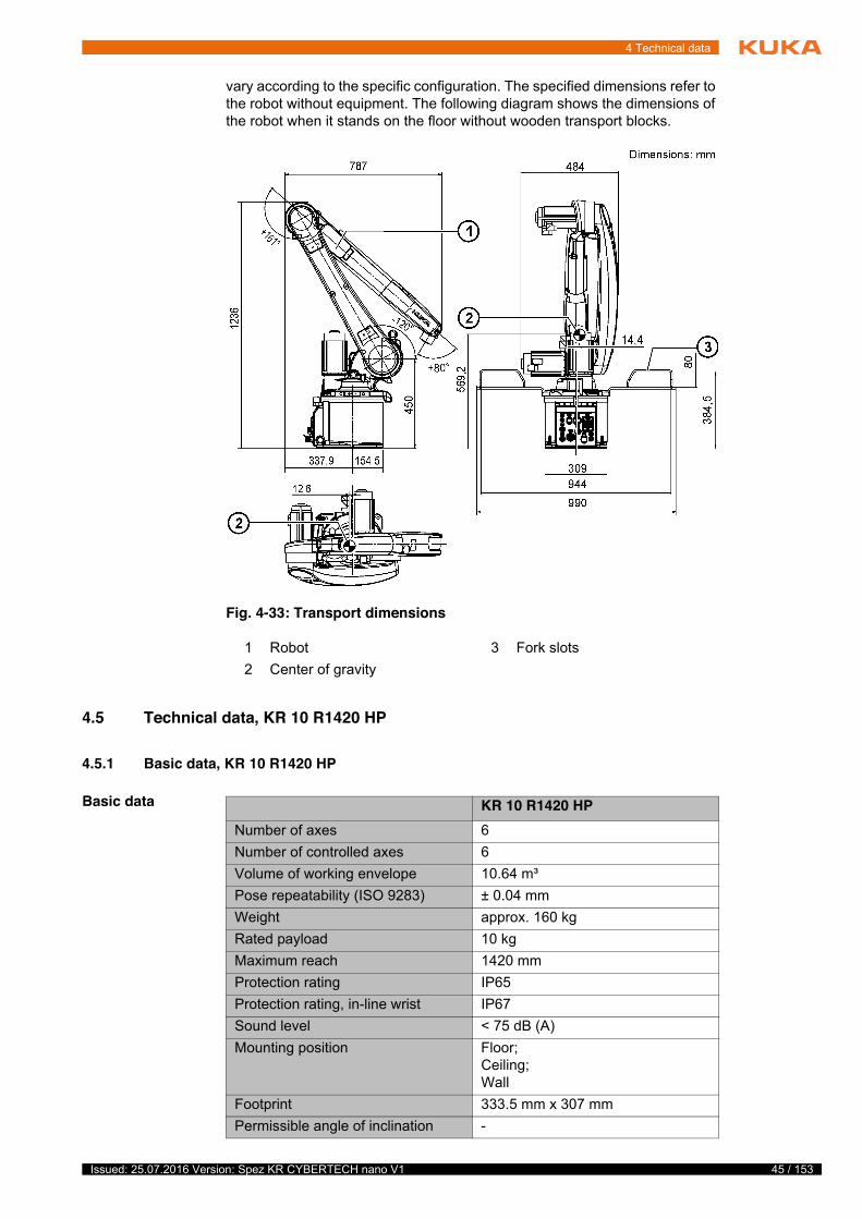
vary according to the specific configuration. The specified dimensions refer to the robot without equipment. The following diagram shows the dimensions of the robot when it stands on the floor without wooden transport blocks.
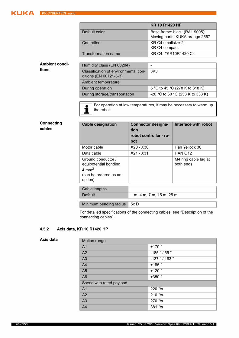
4.5 Technical data, KR 10 R1420 HP
4.5.1 Basic data, KR 10 R1420 HP
Basic data
Fig. 4-33: Transport dimensions
1 Robot 3 Fork slots2 Center of gravity
KR 10 R1420 HPNumber of axes 6Number of controlled axes 6Volume of working envelope 10.64 m³Pose repeatability (ISO 9283) ± 0.04 mmWeight approx. 160 kgRated payload 10 kgMaximum reach 1420 mmProtection rating IP65Protection rating, in-line wrist IP67Sound level < 75 dB (A)Mounting position Floor;
Ceiling;Wall
Footprint 333.5 mm x 307 mmPermissible angle of inclination -
46 / 153 Issued: 25.07.2016 Version: Spez KR CYBERTECH nano V1
KR CYBERTECH nano
Ambient condi-tions
Connecting cables
For detailed specifications of the connecting cables, see “Description of the connecting cables”.
4.5.2 Axis data, KR 10 R1420 HP
Axis data
Default color Base frame: black (RAL 9005);Moving parts: KUKA orange 2567
Controller KR C4 smallsize-2;KR C4 compact
Transformation name KR C4: #KR10R1420 C4
KR 10 R1420 HP
Humidity class (EN 60204) -Classification of environmental con-ditions (EN 60721-3-3)
3K3
Ambient temperatureDuring operation 5 °C to 45 °C (278 K to 318 K)During storage/transportation -20 °C to 60 °C (253 K to 333 K)
For operation at low temperatures, it may be necessary to warm up the robot.
Cable designation Connector designa-tionrobot controller - ro-bot
Interface with robot
Motor cable X20 - X30 Han Yellock 30Data cable X21 - X31 HAN Q12Ground conductor / equipotential bonding4 mm2
(can be ordered as an option)
M4 ring cable lug at both ends
Cable lengthsDefault 1 m, 4 m, 7 m, 15 m, 25 m
Minimum bending radius 5x D
Motion rangeA1 ±170 °A2 -185 ° / 65 °A3 -137 ° / 163 °A4 ±185 °A5 ±120 °A6 ±350 °Speed with rated payloadA1 220 °/sA2 210 °/sA3 270 °/sA4 381 °/s
47 / 153Issued: 25.07.2016 Version: Spez KR CYBERTECH nano V1
4 Technical data
The direction of motion and the arrangement of the individual axes may be not-ed from the following diagram.
Mastering positions
Working envelope
The following diagrams show the shape and size of the working envelope for these variants of this product family.
The reference point for the working envelope is the intersection of axes 4 and 5.
A5 311 °/sA6 492 °/s
Fig. 4-34: Direction of rotation of robot axes
Mastering positionA1 38 °A2 -110 °A3 110 °A4 0 °A5 0 °A6 0 °
48 / 153 Issued: 25.07.2016 Version: Spez KR CYBERTECH nano V1
KR CYBERTECH nano
Inclined instal-lation
The robot can installed anywhere from a 0° position (floor) to a 180° position (ceiling). This type of installation results in limitations to the range of motion in the plus and minus directions about axis 1. The following figure shows the pos-
Fig. 4-35: Working envelope, side view, KR 10 R1420 HP
Fig. 4-36: Working envelope, top view, KR 10 R1420 HP
49 / 153Issued: 25.07.2016 Version: Spez KR CYBERTECH nano V1
4 Technical data
sible limitation of the motion range of axis 1, as a function of the angle of incli-nation of the robot.
The inclination angles for the robot must be entered correctly into the controller if the robot is not operated in the floor-mounted position. A configuration of the angles is possible via WorkVisual.
The inclination angles for an unchanged main working direction of the robot:
Floor: A:0°, B:0°, C:0°
Wall: A:0°, B:90°, C:0°
Ceiling: A:0°, B:0°, C:180°
4.5.3 Payloads, KR 10 R1420 HP
Payloads
The inclined installation angles must be individually checked and entered. An incorrectly entered inclined in-
stallation angle can lead to unforeseen motion and/or to an overload and, po-tentially, damage to the robot.
Fig. 4-37: Motion range, axis 1 at an inclined position
Rated payload 10 kgRated mass moment of inertia 0.1 kgm²Rated total load 20 kgRated supplementary load, base frame
0 kg
50 / 153 Issued: 25.07.2016 Version: Spez KR CYBERTECH nano V1
KR CYBERTECH nano
Load center of gravity
For all payloads, the load center of gravity refers to the distance from the face of the mounting flange on axis 6. Refer to the payload diagram for the nominal distance.
Payload diagram
Maximum supplementary load, base frame
0 kg
Rated supplementary load, rotating column
0 kg
Maximum supplementary load, rotating column
20 kg
Rated supplementary load, link arm 0 kgMaximum supplementary load, link arm
15 kg
Rated supplementary load, arm 10 kgMaximum supplementary load, arm 15 kgNominal distance to load center of gravityLxy 100 mmLz 80 mm
Fig. 4-38: Load center of gravity
This loading curve corresponds to the maximum load ca-pacity. Both values (payload and mass moment of iner-
tia) must be checked in all cases. Exceeding this capacity will reduce the service life of the robot and overload the motors and the gears; in any such case the KUKA Roboter GmbH must be consulted beforehand.The values determined here are necessary for planning the robot application. For commissioning the robot, additional input data are required in accor-dance with the operating and programming instructions of the KUKA System Software.The mass inertia must be verified using KUKA.Load. It is imperative for the load data to be entered in the robot controller!
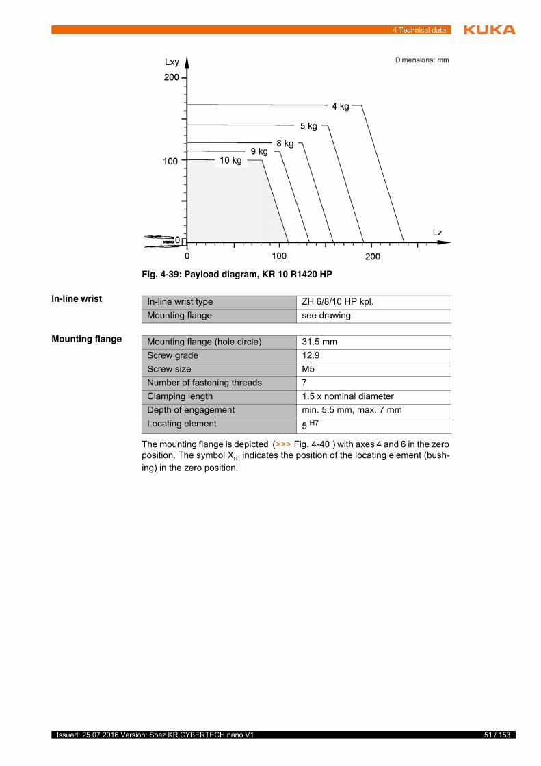
51 / 153Issued: 25.07.2016 Version: Spez KR CYBERTECH nano V1
4 Technical data
In-line wrist
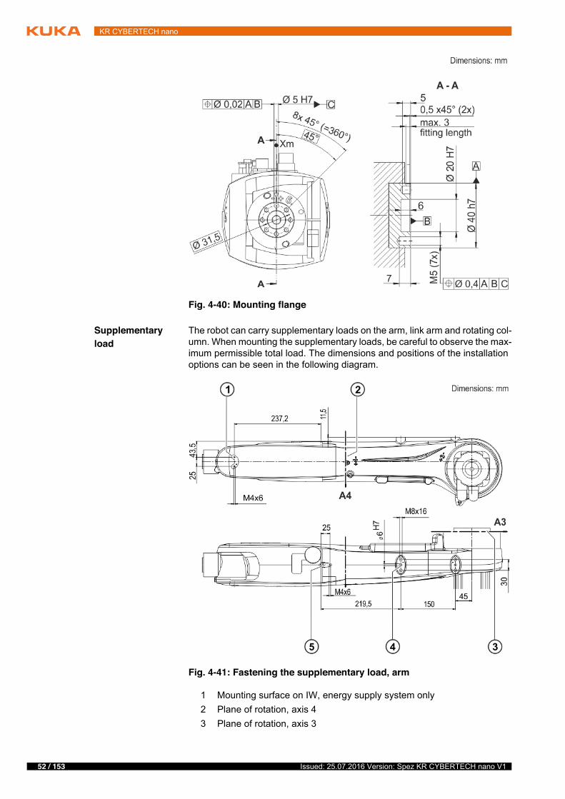
Mounting flange
The mounting flange is depicted (>>> Fig. 4-40 ) with axes 4 and 6 in the zero position. The symbol Xm indicates the position of the locating element (bush-ing) in the zero position.
Fig. 4-39: Payload diagram, KR 10 R1420 HP
In-line wrist type ZH 6/8/10 HP kpl.Mounting flange see drawing
Mounting flange (hole circle) 31.5 mmScrew grade 12.9Screw size M5Number of fastening threads 7Clamping length 1.5 x nominal diameterDepth of engagement min. 5.5 mm, max. 7 mmLocating element 5 H7
52 / 153 Issued: 25.07.2016 Version: Spez KR CYBERTECH nano V1
KR CYBERTECH nano
Supplementary load
The robot can carry supplementary loads on the arm, link arm and rotating col-umn. When mounting the supplementary loads, be careful to observe the max-imum permissible total load. The dimensions and positions of the installation options can be seen in the following diagram.
Fig. 4-40: Mounting flange
Fig. 4-41: Fastening the supplementary load, arm
1 Mounting surface on IW, energy supply system only2 Plane of rotation, axis 43 Plane of rotation, axis 3

53 / 153Issued: 25.07.2016 Version: Spez KR CYBERTECH nano V1
4 Technical data
4.5.4 Loads acting on the mounting base KR 10 R1420 HP
Loads acting on the mounting base
The specified forces and moments already include the payload and the inertia force (weight) of the robot.
4 Mounting surface on arm5 Mounting surface on IW, energy supply system only
Fig. 4-42: Fastening the supplementary load, link arm/rotating column
1 Mounting surface on link arm2 Mounting surface on rotating column, both sides
Foundation loads for floor mounting positionF(v normal) 2469 NF(v max) 2599 NF(h normal) 1114 NF(h max) 1376 NM(k normal) 1523 NmM(k max) 2040 NmM(r normal) 1029 NmM(r max) 1149 NmFoundation loads for ceiling mounting positionF(v normal) 2712 NF(v max) 2794 NF(h normal) 1282 NF(h max) 1624 NM(k normal) 1832 NmM(k max) 2329 NmM(r normal) 1029 NmM(r max) 1149 Nm
54 / 153 Issued: 25.07.2016 Version: Spez KR CYBERTECH nano V1
KR CYBERTECH nano
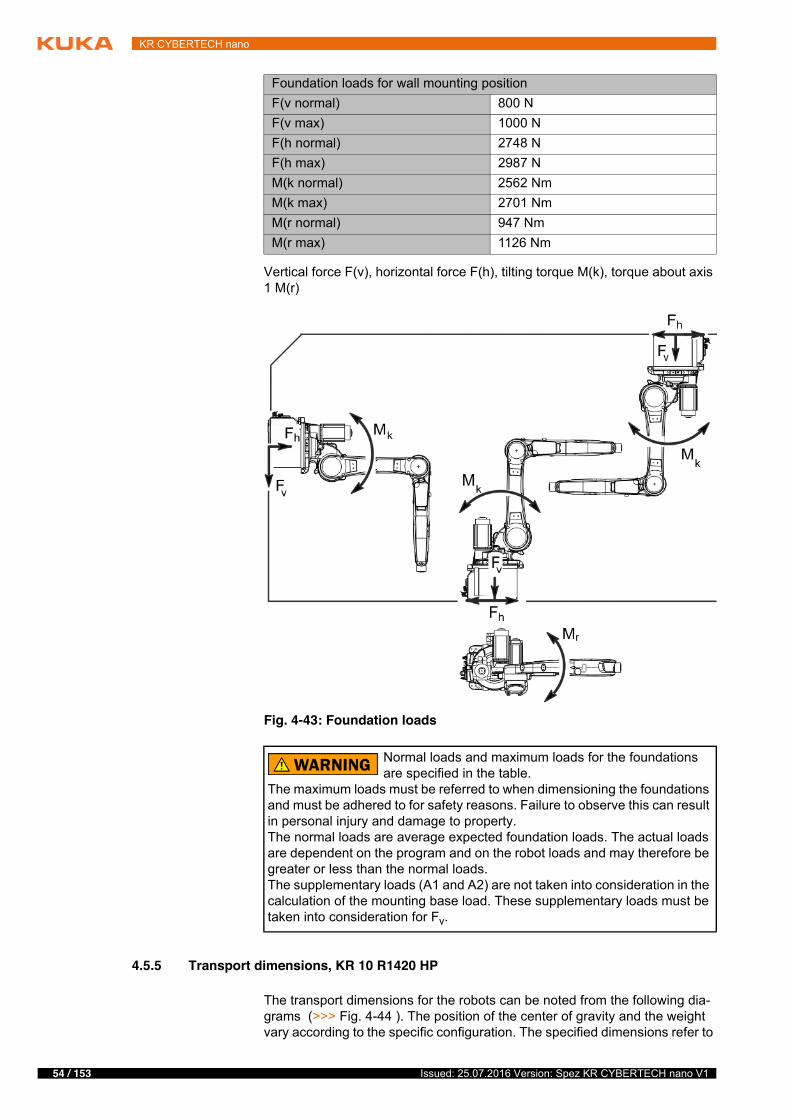
Vertical force F(v), horizontal force F(h), tilting torque M(k), torque about axis 1 M(r)
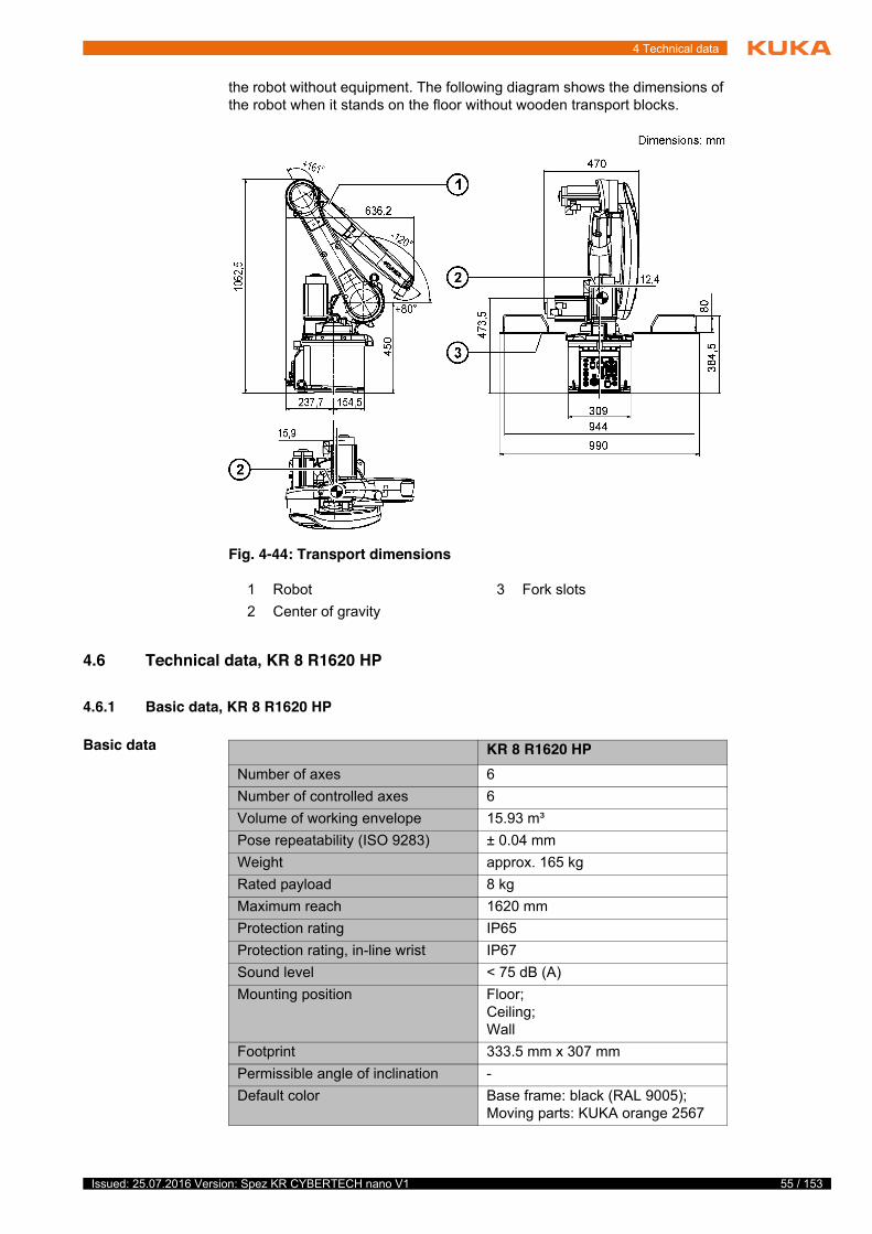
4.5.5 Transport dimensions, KR 10 R1420 HP
The transport dimensions for the robots can be noted from the following dia-grams (>>> Fig. 4-44 ). The position of the center of gravity and the weight vary according to the specific configuration. The specified dimensions refer to
Foundation loads for wall mounting positionF(v normal) 800 NF(v max) 1000 NF(h normal) 2748 NF(h max) 2987 NM(k normal) 2562 NmM(k max) 2701 NmM(r normal) 947 NmM(r max) 1126 Nm
Fig. 4-43: Foundation loads
Normal loads and maximum loads for the foundations are specified in the table.
The maximum loads must be referred to when dimensioning the foundations and must be adhered to for safety reasons. Failure to observe this can result in personal injury and damage to property.The normal loads are average expected foundation loads. The actual loads are dependent on the program and on the robot loads and may therefore be greater or less than the normal loads.The supplementary loads (A1 and A2) are not taken into consideration in the calculation of the mounting base load. These supplementary loads must be taken into consideration for Fv.
55 / 153Issued: 25.07.2016 Version: Spez KR CYBERTECH nano V1
4 Technical data
the robot without equipment. The following diagram shows the dimensions of the robot when it stands on the floor without wooden transport blocks.
4.6 Technical data, KR 8 R1620 HP
4.6.1 Basic data, KR 8 R1620 HP
Basic data
Fig. 4-44: Transport dimensions
1 Robot 3 Fork slots2 Center of gravity
KR 8 R1620 HPNumber of axes 6Number of controlled axes 6Volume of working envelope 15.93 m³Pose repeatability (ISO 9283) ± 0.04 mmWeight approx. 165 kgRated payload 8 kgMaximum reach 1620 mmProtection rating IP65Protection rating, in-line wrist IP67Sound level < 75 dB (A)Mounting position Floor;
Ceiling;Wall
Footprint 333.5 mm x 307 mmPermissible angle of inclination -Default color Base frame: black (RAL 9005);
Moving parts: KUKA orange 2567

56 / 153 Issued: 25.07.2016 Version: Spez KR CYBERTECH nano V1
KR CYBERTECH nano
Ambient condi-tions
Connecting cables
For detailed specifications of the connecting cables, see “Description of the connecting cables”.
4.6.2 Axis data, KR 8 R1620 HP
Axis data
Controller KR C4 smallsize-2;KR C4 compact
Transformation name KR C4: #KR8R1620 C4
KR 8 R1620 HP
Humidity class (EN 60204) -Classification of environmental con-ditions (EN 60721-3-3)
3K3
Ambient temperatureDuring operation 5 °C to 45 °C (278 K to 318 K)During storage/transportation -20 °C to 60 °C (253 K to 333 K)
For operation at low temperatures, it may be necessary to warm up the robot.
Cable designation Connector designa-tionrobot controller - ro-bot
Interface with robot
Motor cable X20 - X30 Han Yellock 30Data cable X21 - X31 HAN Q12Ground conductor / equipotential bonding4 mm2
(can be ordered as an option)
M4 ring cable lug at both ends
Cable lengthsDefault 1 m, 4 m, 7 m, 15 m, 25 m
Minimum bending radius 5x D
Motion rangeA1 ±170 °A2 -185 ° / 65 °A3 -137 ° / 163 °A4 ±185 °A5 ±120 °A6 ±350 °Speed with rated payloadA1 220 °/sA2 210 °/sA3 270 °/sA4 381 °/sA5 311 °/sA6 492 °/s
57 / 153Issued: 25.07.2016 Version: Spez KR CYBERTECH nano V1
4 Technical data
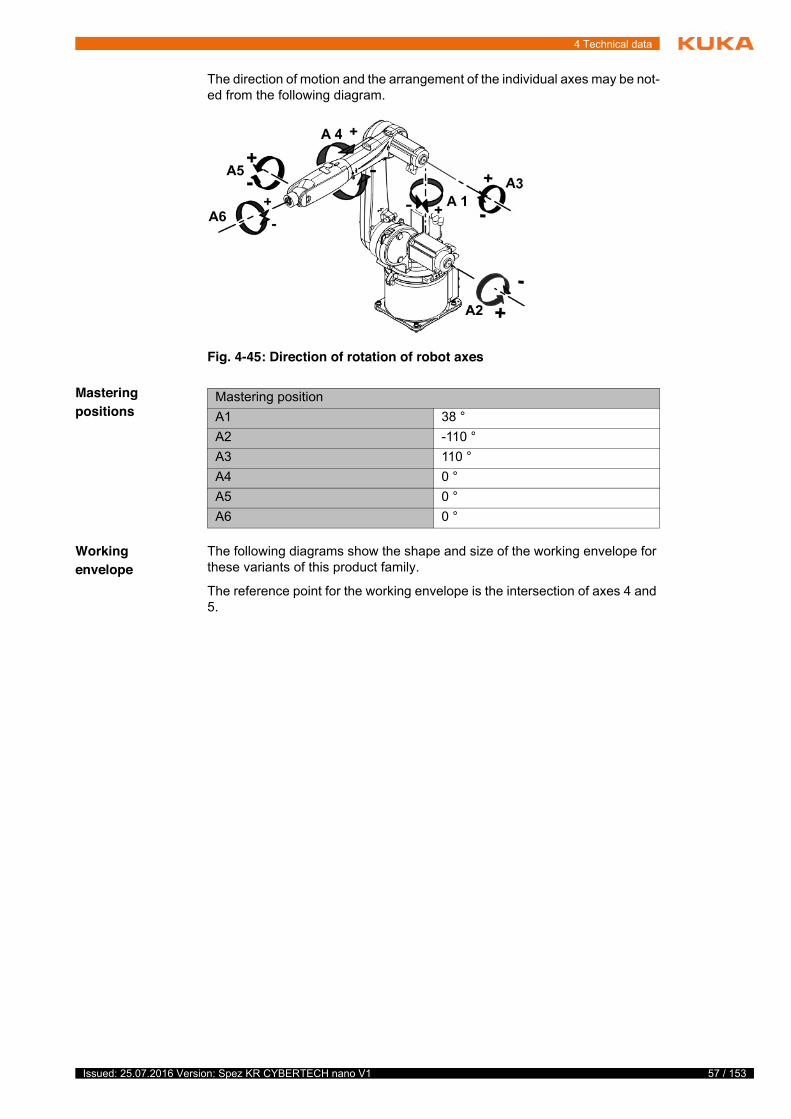
The direction of motion and the arrangement of the individual axes may be not-ed from the following diagram.
Mastering positions
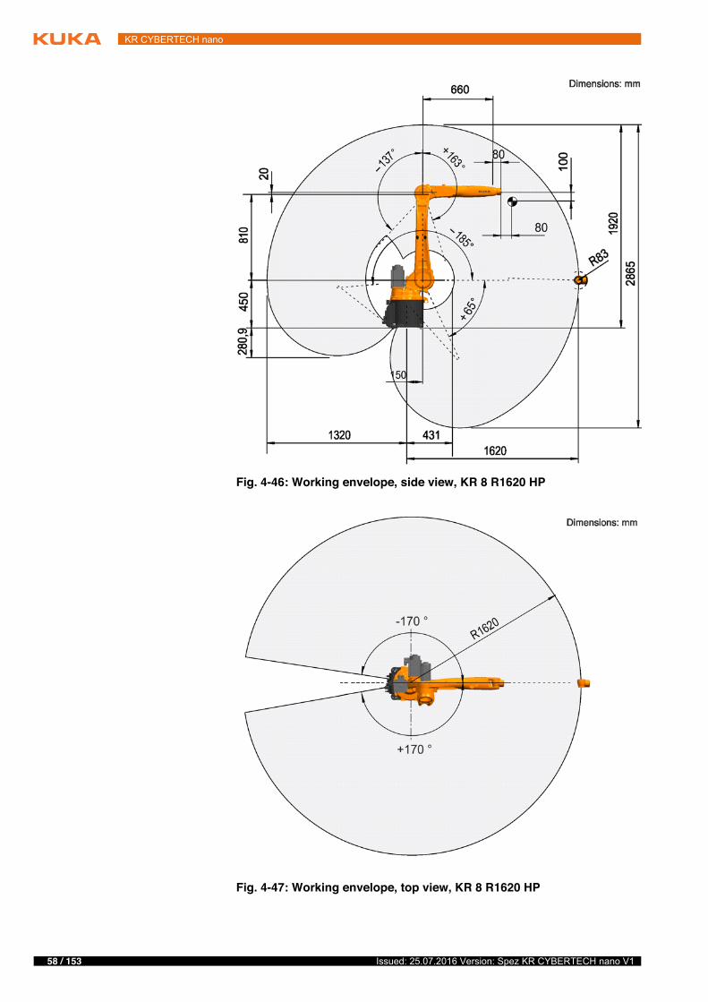
Working envelope
The following diagrams show the shape and size of the working envelope for these variants of this product family.
The reference point for the working envelope is the intersection of axes 4 and 5.
Fig. 4-45: Direction of rotation of robot axes
Mastering positionA1 38 °A2 -110 °A3 110 °A4 0 °A5 0 °A6 0 °
58 / 153 Issued: 25.07.2016 Version: Spez KR CYBERTECH nano V1
KR CYBERTECH nano
Fig. 4-46: Working envelope, side view, KR 8 R1620 HP
Fig. 4-47: Working envelope, top view, KR 8 R1620 HP

59 / 153Issued: 25.07.2016 Version: Spez KR CYBERTECH nano V1
4 Technical data
Inclined instal-lation
The robot can installed anywhere from a 0° position (floor) to a 180° position (ceiling). This type of installation results in limitations to the range of motion in the plus and minus directions about axis 1. The following figure shows the pos-sible limitation of the motion range of axis 1, as a function of the angle of incli-nation of the robot.
The inclination angles for the robot must be entered correctly into the controller if the robot is not operated in the floor-mounted position. A configuration of the angles is possible via WorkVisual.
The inclination angles for an unchanged main working direction of the robot:
Floor: A:0°, B:0°, C:0°
Wall: A:0°, B:90°, C:0°
Ceiling: A:0°, B:0°, C:180°
4.6.3 Payloads, KR 8 R1620 HP
Payloads
The inclined installation angles must be individually checked and entered. An incorrectly entered inclined in-
stallation angle can lead to unforeseen motion and/or to an overload and, po-tentially, damage to the robot.
Fig. 4-48: Motion range, axis 1 at an inclined position
Rated payload 8 kgRated mass moment of inertia 0.1 kgm²Rated total load 18 kg

60 / 153 Issued: 25.07.2016 Version: Spez KR CYBERTECH nano V1
KR CYBERTECH nano
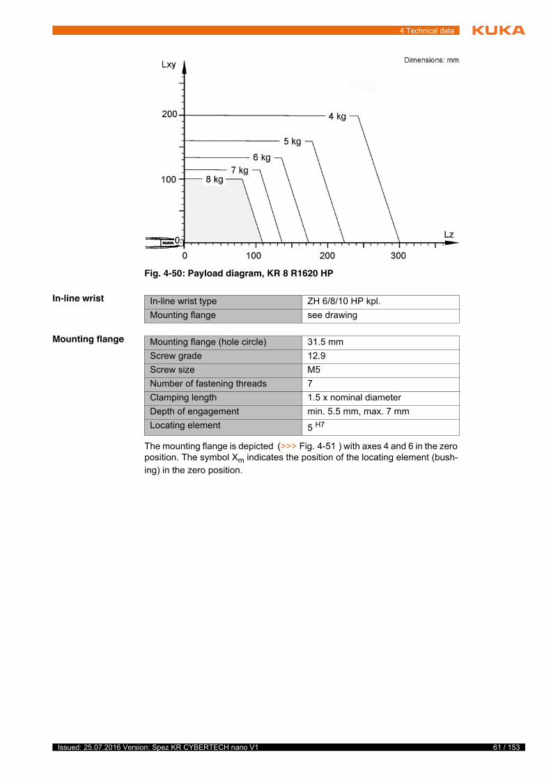
Load center of gravity
For all payloads, the load center of gravity refers to the distance from the face of the mounting flange on axis 6. Refer to the payload diagram for the nominal distance.
Payload diagram
Rated supplementary load, base frame
0 kg
Maximum supplementary load, base frame
0 kg
Rated supplementary load, rotating column
0 kg
Maximum supplementary load, rotating column
20 kg
Rated supplementary load, link arm 0 kgMaximum supplementary load, link arm
15 kg
Rated supplementary load, arm 10 kgMaximum supplementary load, arm 15 kgNominal distance to load center of gravityLxy 100 mmLz 80 mm
Fig. 4-49: Load center of gravity
This loading curve corresponds to the maximum load ca-pacity. Both values (payload and mass moment of iner-
tia) must be checked in all cases. Exceeding this capacity will reduce the service life of the robot and overload the motors and the gears; in any such case the KUKA Roboter GmbH must be consulted beforehand.The values determined here are necessary for planning the robot application. For commissioning the robot, additional input data are required in accor-dance with the operating and programming instructions of the KUKA System Software.The mass inertia must be verified using KUKA.Load. It is imperative for the load data to be entered in the robot controller!
61 / 153Issued: 25.07.2016 Version: Spez KR CYBERTECH nano V1
4 Technical data
In-line wrist
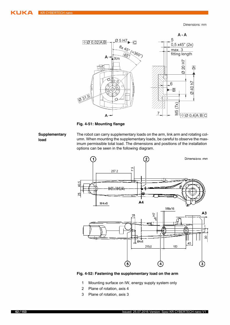
Mounting flange
The mounting flange is depicted (>>> Fig. 4-51 ) with axes 4 and 6 in the zero position. The symbol Xm indicates the position of the locating element (bush-ing) in the zero position.
Fig. 4-50: Payload diagram, KR 8 R1620 HP
In-line wrist type ZH 6/8/10 HP kpl.Mounting flange see drawing
Mounting flange (hole circle) 31.5 mmScrew grade 12.9Screw size M5Number of fastening threads 7Clamping length 1.5 x nominal diameterDepth of engagement min. 5.5 mm, max. 7 mmLocating element 5 H7
62 / 153 Issued: 25.07.2016 Version: Spez KR CYBERTECH nano V1
KR CYBERTECH nano
Supplementary load
The robot can carry supplementary loads on the arm, link arm and rotating col-umn. When mounting the supplementary loads, be careful to observe the max-imum permissible total load. The dimensions and positions of the installation options can be seen in the following diagram.
Fig. 4-51: Mounting flange
Fig. 4-52: Fastening the supplementary load on the arm
1 Mounting surface on IW, energy supply system only2 Plane of rotation, axis 43 Plane of rotation, axis 3
63 / 153Issued: 25.07.2016 Version: Spez KR CYBERTECH nano V1
4 Technical data
4.6.4 Loads acting on the mounting base KR 8 R1620 HP
Loads acting on the mounting base
The specified forces and moments already include the payload and the inertia force (weight) of the robot.
4 Mounting surface on arm5 Mounting surface on IW, energy supply system only
Fig. 4-53: Fastening the supplementary load on the link arm/rotating col-umn
1 Mounting surface on link arm2 Mounting surface on rotating column, both sides
Foundation loads for floor mounting positionF(v normal) 2469 NF(v max) 2599 NF(h normal) 1114 NF(h max) 1376 NM(k normal) 1523 NmM(k max) 2040 NmM(r normal) 1029 NmM(r max) 1149 NmFoundation loads for ceiling mounting positionF(v normal) 2712 NF(v max) 2794 NF(h normal) 1282 NF(h max) 1624 NM(k normal) 1832 Nm

64 / 153 Issued: 25.07.2016 Version: Spez KR CYBERTECH nano V1
KR CYBERTECH nano
Vertical force F(v), horizontal force F(h), tilting torque M(k), torque about axis 1 M(r)
M(k max) 2329 NmM(r normal) 1029 NmM(r max) 1149 NmFoundation loads for wall mounting positionF(v normal) 800 NF(v max) 1000 NF(h normal) 2748 NF(h max) 2987 NM(k normal) 2562 NmM(k max) 2701 NmM(r normal) 947 NmM(r max) 1126 Nm
Fig. 4-54: Mounting base loads
Normal loads and maximum loads for the foundations are specified in the table.
The maximum loads must be referred to when dimensioning the foundations and must be adhered to for safety reasons. Failure to observe this can result in personal injury and damage to property.The normal loads are average expected foundation loads. The actual loads are dependent on the program and on the robot loads and may therefore be greater or less than the normal loads.The supplementary loads (A1 and A2) are not taken into consideration in the calculation of the mounting base load. These supplementary loads must be taken into consideration for Fv.
65 / 153Issued: 25.07.2016 Version: Spez KR CYBERTECH nano V1
4 Technical data
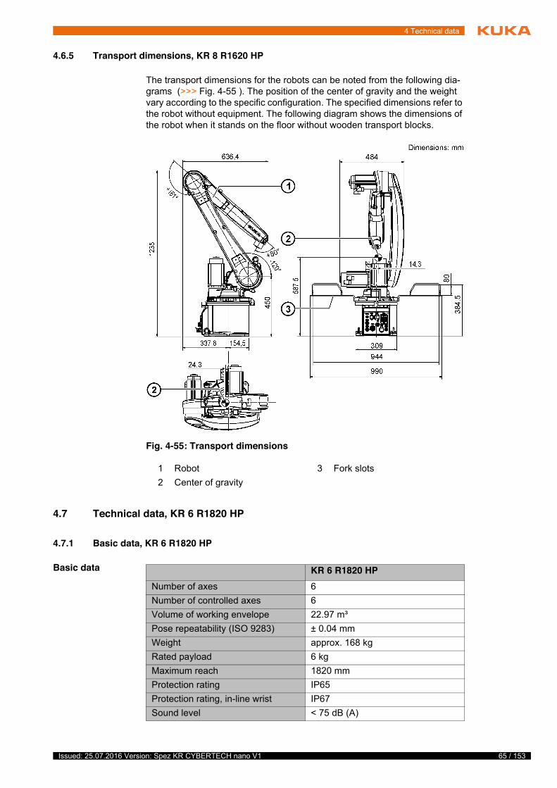
4.6.5 Transport dimensions, KR 8 R1620 HP
The transport dimensions for the robots can be noted from the following dia-grams (>>> Fig. 4-55 ). The position of the center of gravity and the weight vary according to the specific configuration. The specified dimensions refer to the robot without equipment. The following diagram shows the dimensions of the robot when it stands on the floor without wooden transport blocks.
4.7 Technical data, KR 6 R1820 HP
4.7.1 Basic data, KR 6 R1820 HP
Basic data
Fig. 4-55: Transport dimensions
1 Robot 3 Fork slots2 Center of gravity
KR 6 R1820 HPNumber of axes 6Number of controlled axes 6Volume of working envelope 22.97 m³Pose repeatability (ISO 9283) ± 0.04 mmWeight approx. 168 kgRated payload 6 kgMaximum reach 1820 mmProtection rating IP65Protection rating, in-line wrist IP67Sound level < 75 dB (A)

66 / 153 Issued: 25.07.2016 Version: Spez KR CYBERTECH nano V1
KR CYBERTECH nano
Ambient condi-tions
Connecting cables
For detailed specifications of the connecting cables, see “Description of the connecting cables”.
4.7.2 Axis data, KR 6 R1820 HP
Axis data
Mounting position Floor;Ceiling;Wall
Footprint 333.5 mm x 307 mmPermissible angle of inclination -Default color Base frame: black (RAL 9005);
Moving parts: KUKA orange 2567Controller KR C4 smallsize-2;
KR C4 compactTransformation name KR C4: #KR6R1820 C4
KR 6 R1820 HP
Humidity class (EN 60204) -Classification of environmental con-ditions (EN 60721-3-3)
3K3
Ambient temperatureDuring operation 5 °C to 45 °C (278 K to 318 K)During storage/transportation -20 °C to 60 °C (253 K to 333 K)
For operation at low temperatures, it may be necessary to warm up the robot.
Cable designation Connector designa-tionrobot controller - ro-bot
Interface with robot
Motor cable X20 - X30 Han Yellock 30Data cable X21 - X31 HAN Q12Ground conductor / equipotential bonding4 mm2
(can be ordered as an option)
M4 ring cable lug at both ends
Cable lengthsDefault 1 m, 4 m, 7 m, 15 m, 25 m
Minimum bending radius 5x D
Motion rangeA1 ±170 °A2 -185 ° / 65 °A3 -137 ° / 163 °A4 ±185 °A5 ±120 °A6 ±350 °Speed with rated payload

67 / 153Issued: 25.07.2016 Version: Spez KR CYBERTECH nano V1
4 Technical data
The direction of motion and the arrangement of the individual axes may be not-ed from the following diagram.
Mastering positions
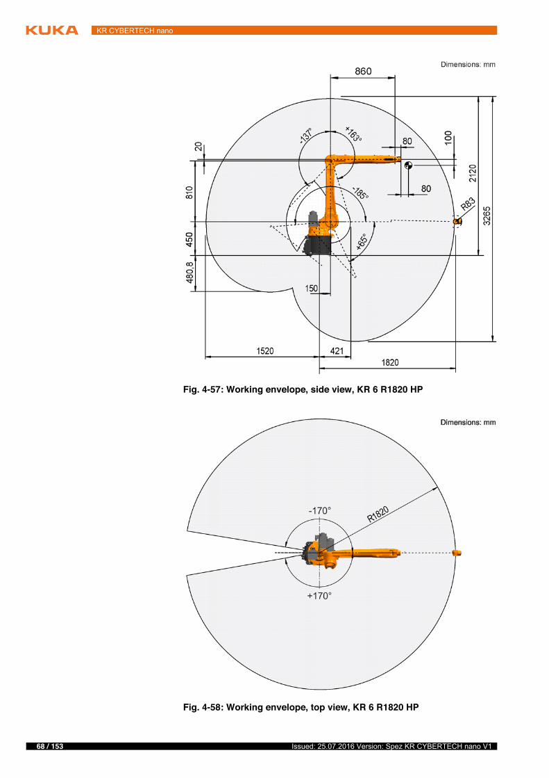
Working envelope
The following diagrams show the shape and size of the working envelope for these variants of this product family.
The reference point for the working envelope is the intersection of axes 4 and 5.
A1 220 °/sA2 210 °/sA3 270 °/sA4 381 °/sA5 311 °/sA6 492 °/s
Fig. 4-56: Direction of rotation of robot axes
Mastering positionA1 38 °A2 -110 °A3 110 °A4 0 °A5 0 °A6 0 °
68 / 153 Issued: 25.07.2016 Version: Spez KR CYBERTECH nano V1
KR CYBERTECH nano
Fig. 4-57: Working envelope, side view, KR 6 R1820 HP
Fig. 4-58: Working envelope, top view, KR 6 R1820 HP

69 / 153Issued: 25.07.2016 Version: Spez KR CYBERTECH nano V1
4 Technical data
Inclined instal-lation
The robot can installed anywhere from a 0° position (floor) to a 180° position (ceiling). This type of installation results in limitations to the range of motion in the plus and minus directions about axis 1. The following figure shows the pos-sible limitation of the motion range of axis 1, as a function of the angle of incli-nation of the robot.
The inclination angles for the robot must be entered correctly into the controller if the robot is not operated in the floor-mounted position. A configuration of the angles is possible via WorkVisual.
The inclination angles for an unchanged main working direction of the robot:
Floor: A:0°, B:0°, C:0°
Wall: A:0°, B:90°, C:0°
Ceiling: A:0°, B:0°, C:180°
4.7.3 Payloads, KR 6 R1820 HP
Payloads
The inclined installation angles must be individually checked and entered. An incorrectly entered inclined in-
stallation angle can lead to unforeseen motion and/or to an overload and, po-tentially, damage to the robot.
Fig. 4-59: Motion range, axis 1 at an inclined position
Rated payload 6 kgRated mass moment of inertia 0.1 kgm²Rated total load 16 kg

70 / 153 Issued: 25.07.2016 Version: Spez KR CYBERTECH nano V1
KR CYBERTECH nano
Load center of gravity
For all payloads, the load center of gravity refers to the distance from the face of the mounting flange on axis 6. Refer to the payload diagram for the nominal distance.
Payload diagram
Rated supplementary load, base frame
0 kg
Maximum supplementary load, base frame
0 kg
Rated supplementary load, rotating column
0 kg
Maximum supplementary load, rotating column
20 kg
Rated supplementary load, link arm 0 kgMaximum supplementary load, link arm
15 kg
Rated supplementary load, arm 10 kgMaximum supplementary load, arm 15 kgNominal distance to load center of gravityLxy 100 mmLz 80 mm
Fig. 4-60: Load center of gravity
This loading curve corresponds to the maximum load ca-pacity. Both values (payload and mass moment of iner-
tia) must be checked in all cases. Exceeding this capacity will reduce the service life of the robot and overload the motors and the gears; in any such case the KUKA Roboter GmbH must be consulted beforehand.The values determined here are necessary for planning the robot application. For commissioning the robot, additional input data are required in accor-dance with the operating and programming instructions of the KUKA System Software.The mass inertia must be verified using KUKA.Load. It is imperative for the load data to be entered in the robot controller!
71 / 153Issued: 25.07.2016 Version: Spez KR CYBERTECH nano V1
4 Technical data
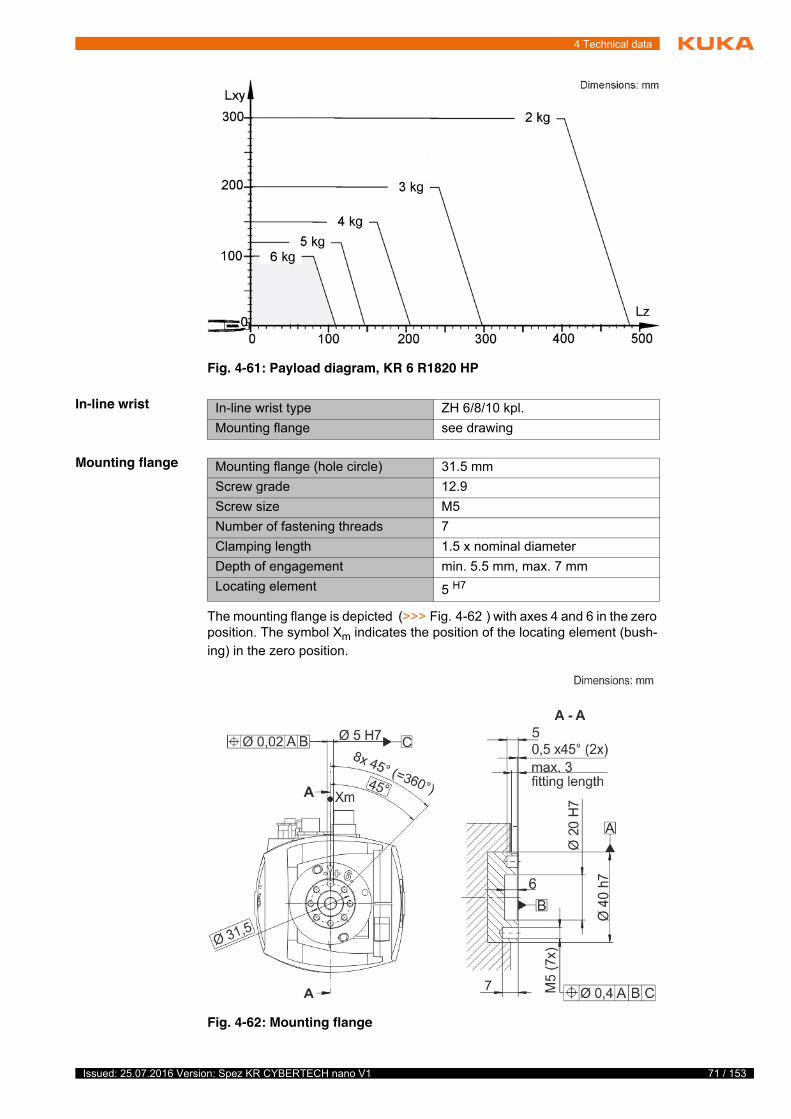
In-line wrist
Mounting flange
The mounting flange is depicted (>>> Fig. 4-62 ) with axes 4 and 6 in the zero position. The symbol Xm indicates the position of the locating element (bush-ing) in the zero position.
Fig. 4-61: Payload diagram, KR 6 R1820 HP
In-line wrist type ZH 6/8/10 kpl.Mounting flange see drawing
Mounting flange (hole circle) 31.5 mmScrew grade 12.9Screw size M5Number of fastening threads 7Clamping length 1.5 x nominal diameterDepth of engagement min. 5.5 mm, max. 7 mmLocating element 5 H7
Fig. 4-62: Mounting flange
72 / 153 Issued: 25.07.2016 Version: Spez KR CYBERTECH nano V1
KR CYBERTECH nano
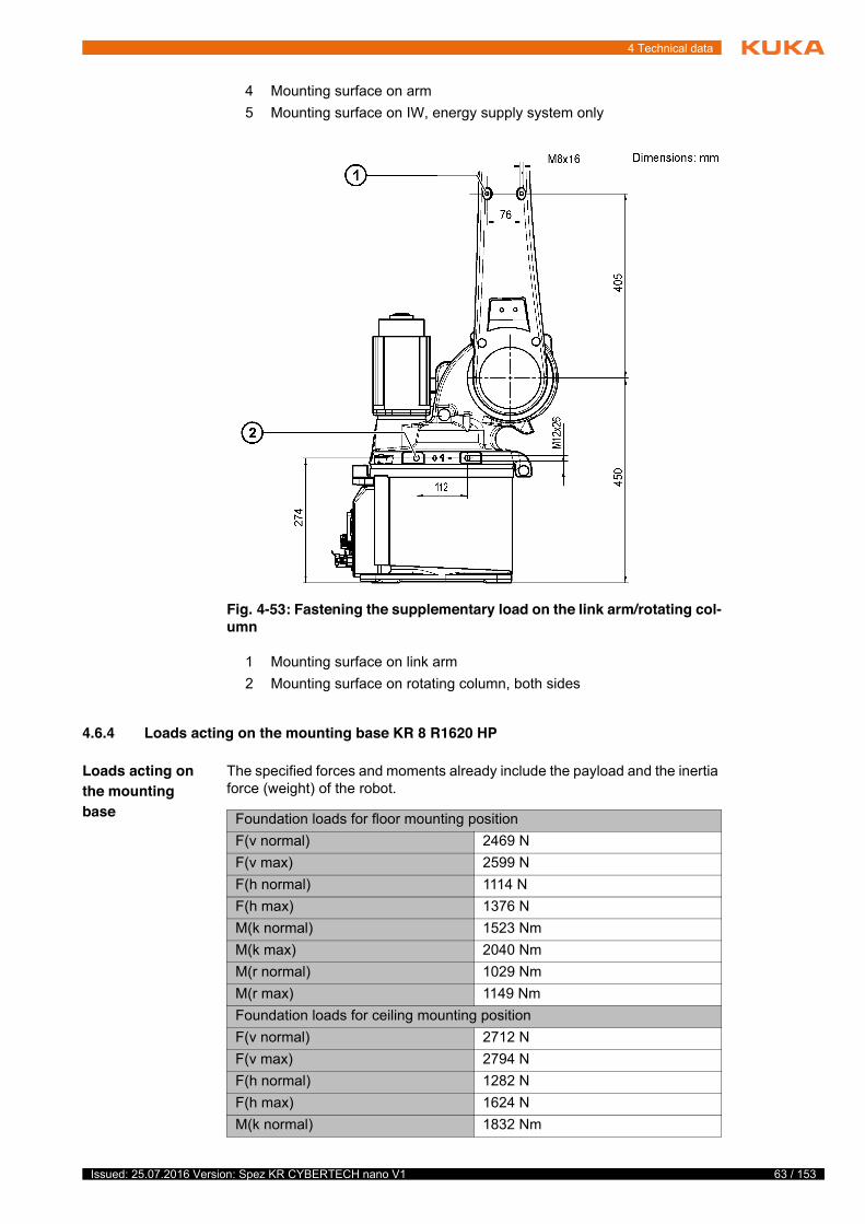
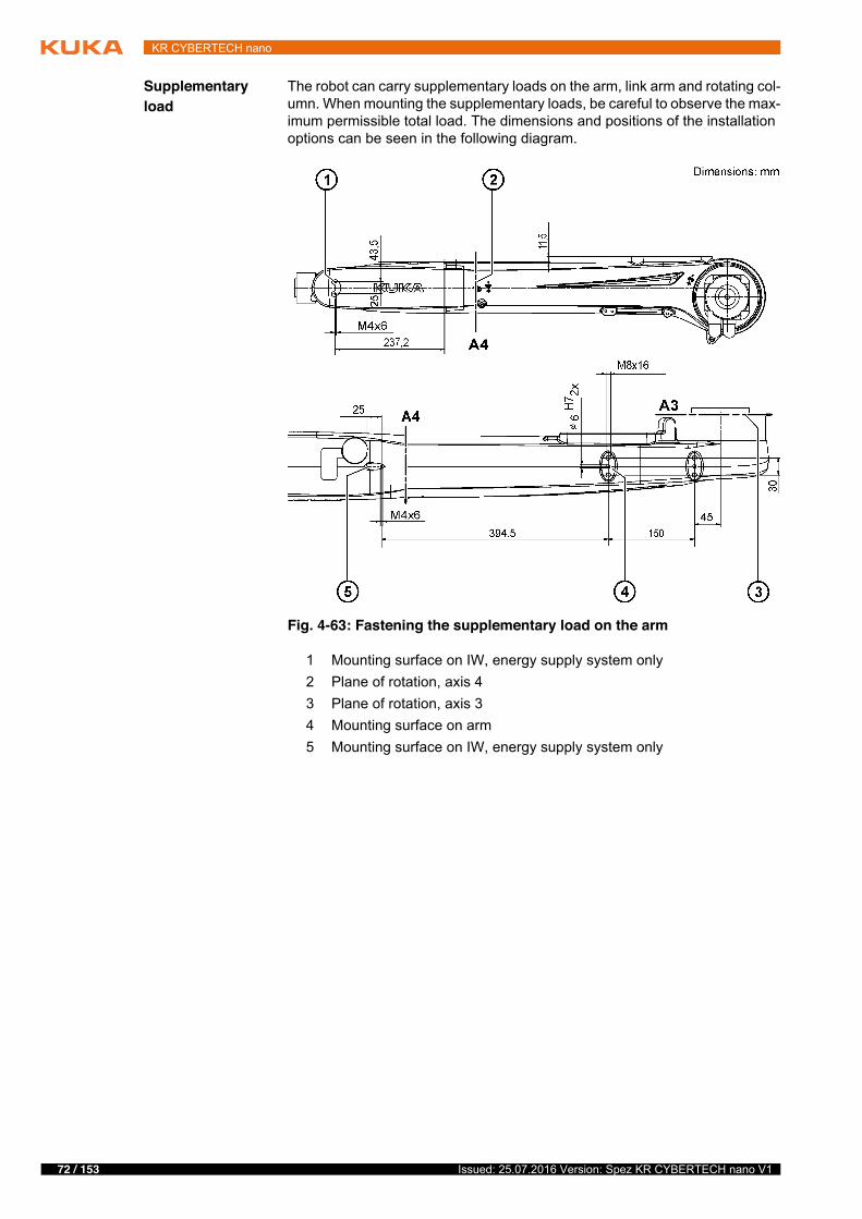
Supplementary load
The robot can carry supplementary loads on the arm, link arm and rotating col-umn. When mounting the supplementary loads, be careful to observe the max-imum permissible total load. The dimensions and positions of the installation options can be seen in the following diagram.
Fig. 4-63: Fastening the supplementary load on the arm
1 Mounting surface on IW, energy supply system only2 Plane of rotation, axis 43 Plane of rotation, axis 34 Mounting surface on arm5 Mounting surface on IW, energy supply system only
73 / 153Issued: 25.07.2016 Version: Spez KR CYBERTECH nano V1
4 Technical data
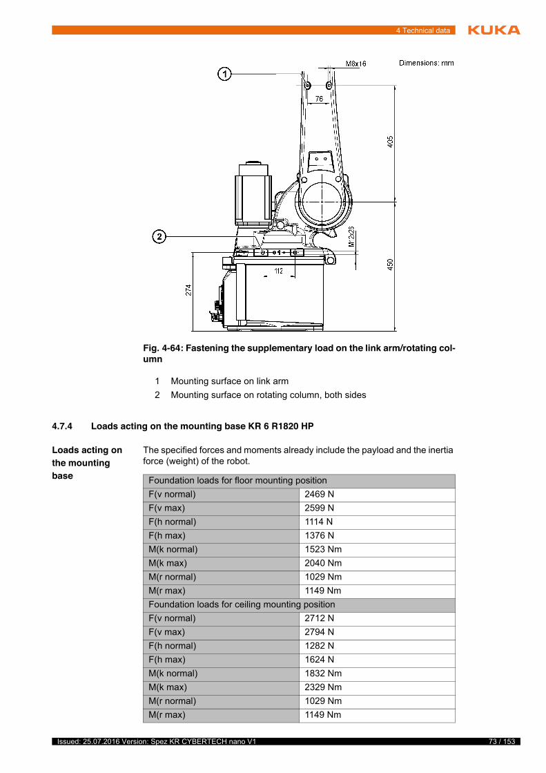
4.7.4 Loads acting on the mounting base KR 6 R1820 HP
Loads acting on the mounting base
The specified forces and moments already include the payload and the inertia force (weight) of the robot.
Fig. 4-64: Fastening the supplementary load on the link arm/rotating col-umn
1 Mounting surface on link arm2 Mounting surface on rotating column, both sides
Foundation loads for floor mounting positionF(v normal) 2469 NF(v max) 2599 NF(h normal) 1114 NF(h max) 1376 NM(k normal) 1523 NmM(k max) 2040 NmM(r normal) 1029 NmM(r max) 1149 NmFoundation loads for ceiling mounting positionF(v normal) 2712 NF(v max) 2794 NF(h normal) 1282 NF(h max) 1624 NM(k normal) 1832 NmM(k max) 2329 NmM(r normal) 1029 NmM(r max) 1149 Nm
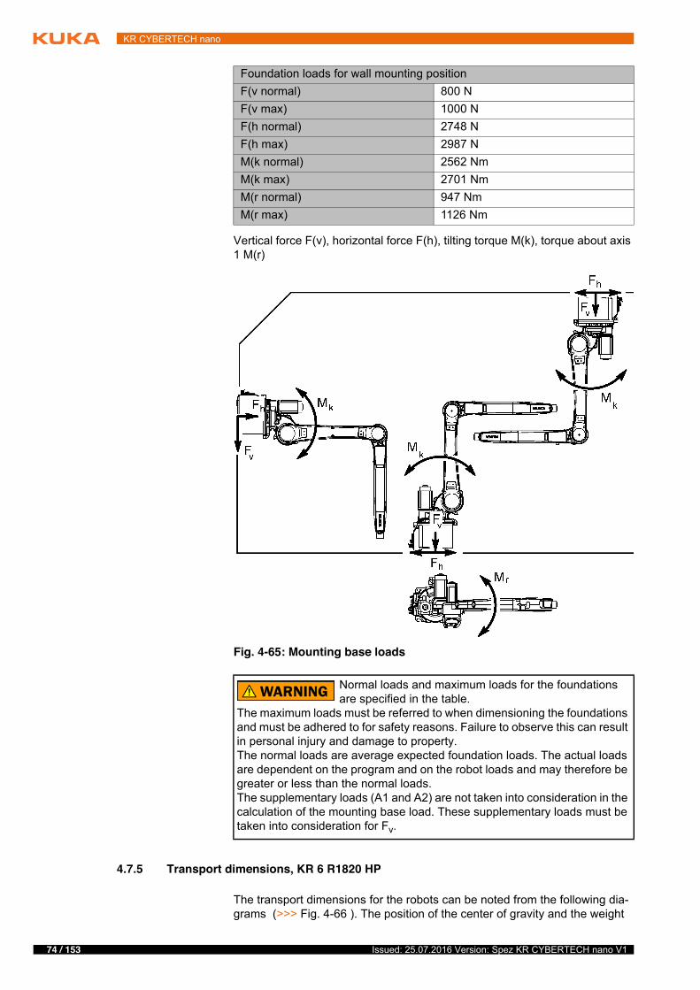
74 / 153 Issued: 25.07.2016 Version: Spez KR CYBERTECH nano V1
KR CYBERTECH nano
Vertical force F(v), horizontal force F(h), tilting torque M(k), torque about axis 1 M(r)
4.7.5 Transport dimensions, KR 6 R1820 HP
The transport dimensions for the robots can be noted from the following dia-grams (>>> Fig. 4-66 ). The position of the center of gravity and the weight
Foundation loads for wall mounting positionF(v normal) 800 NF(v max) 1000 NF(h normal) 2748 NF(h max) 2987 NM(k normal) 2562 NmM(k max) 2701 NmM(r normal) 947 NmM(r max) 1126 Nm
Fig. 4-65: Mounting base loads
Normal loads and maximum loads for the foundations are specified in the table.
The maximum loads must be referred to when dimensioning the foundations and must be adhered to for safety reasons. Failure to observe this can result in personal injury and damage to property.The normal loads are average expected foundation loads. The actual loads are dependent on the program and on the robot loads and may therefore be greater or less than the normal loads.The supplementary loads (A1 and A2) are not taken into consideration in the calculation of the mounting base load. These supplementary loads must be taken into consideration for Fv.
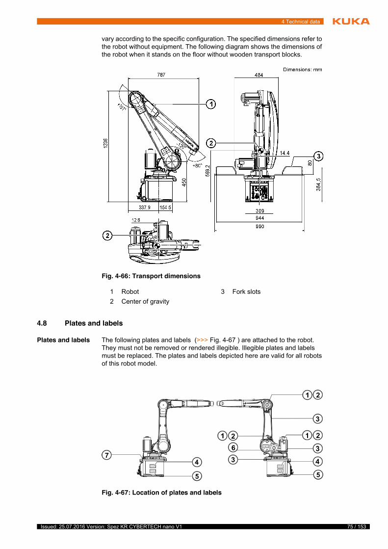
75 / 153Issued: 25.07.2016 Version: Spez KR CYBERTECH nano V1
4 Technical data
vary according to the specific configuration. The specified dimensions refer to the robot without equipment. The following diagram shows the dimensions of the robot when it stands on the floor without wooden transport blocks.
4.8 Plates and labels
Plates and labels The following plates and labels (>>> Fig. 4-67 ) are attached to the robot. They must not be removed or rendered illegible. Illegible plates and labels must be replaced. The plates and labels depicted here are valid for all robots of this robot model.
Fig. 4-66: Transport dimensions
1 Robot 3 Fork slots2 Center of gravity
Fig. 4-67: Location of plates and labels
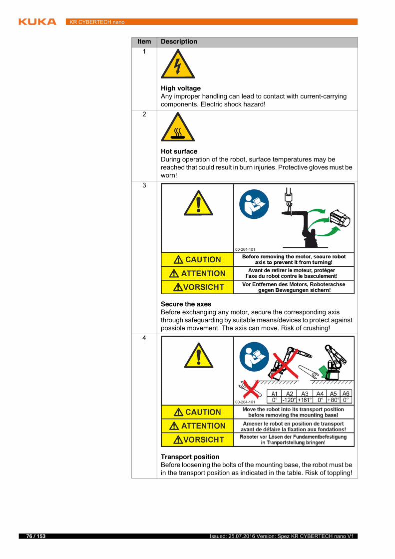
76 / 153 Issued: 25.07.2016 Version: Spez KR CYBERTECH nano V1
KR CYBERTECH nano
Item Description1
High voltageAny improper handling can lead to contact with current-carrying components. Electric shock hazard!
2
Hot surfaceDuring operation of the robot, surface temperatures may be reached that could result in burn injuries. Protective gloves must be worn!
3
Secure the axesBefore exchanging any motor, secure the corresponding axis through safeguarding by suitable means/devices to protect against possible movement. The axis can move. Risk of crushing!
4
Transport positionBefore loosening the bolts of the mounting base, the robot must be in the transport position as indicated in the table. Risk of toppling!
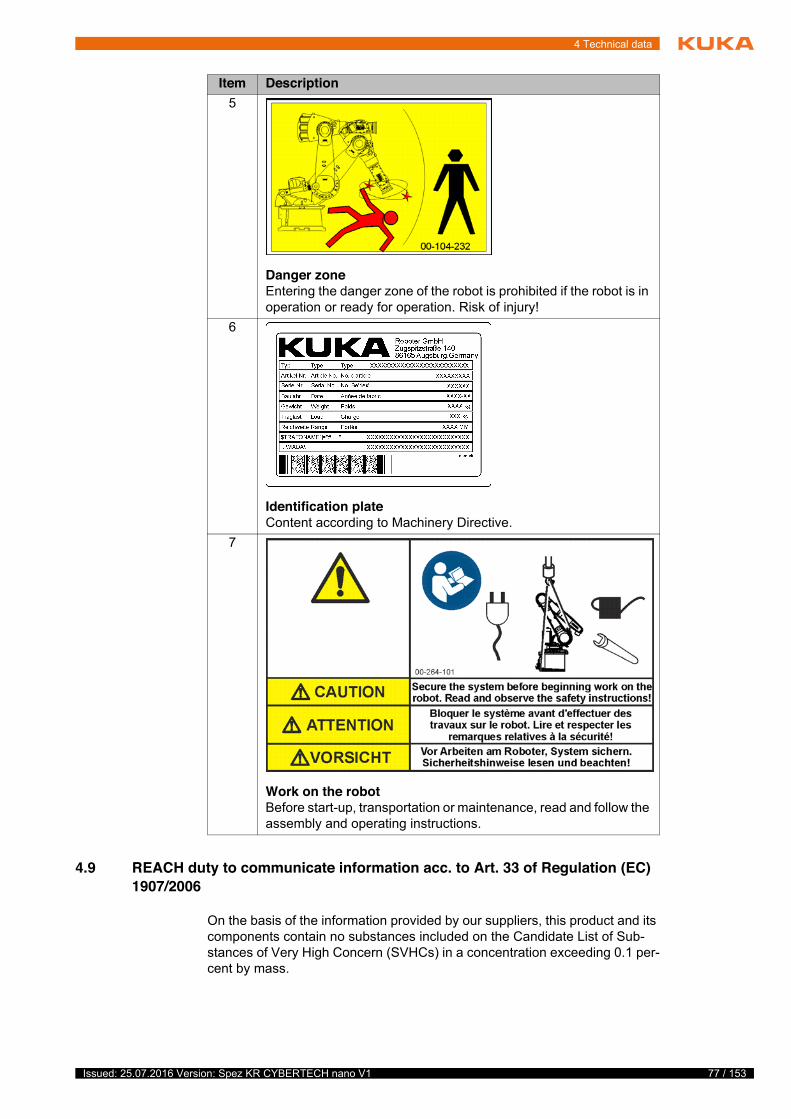
77 / 153Issued: 25.07.2016 Version: Spez KR CYBERTECH nano V1
4 Technical data
4.9 REACH duty to communicate information acc. to Art. 33 of Regulation (EC) 1907/2006
On the basis of the information provided by our suppliers, this product and its components contain no substances included on the Candidate List of Sub-stances of Very High Concern (SVHCs) in a concentration exceeding 0.1 per-cent by mass.
5
Danger zoneEntering the danger zone of the robot is prohibited if the robot is in operation or ready for operation. Risk of injury!
6
Identification plateContent according to Machinery Directive.
7
Work on the robotBefore start-up, transportation or maintenance, read and follow the assembly and operating instructions.
Item Description
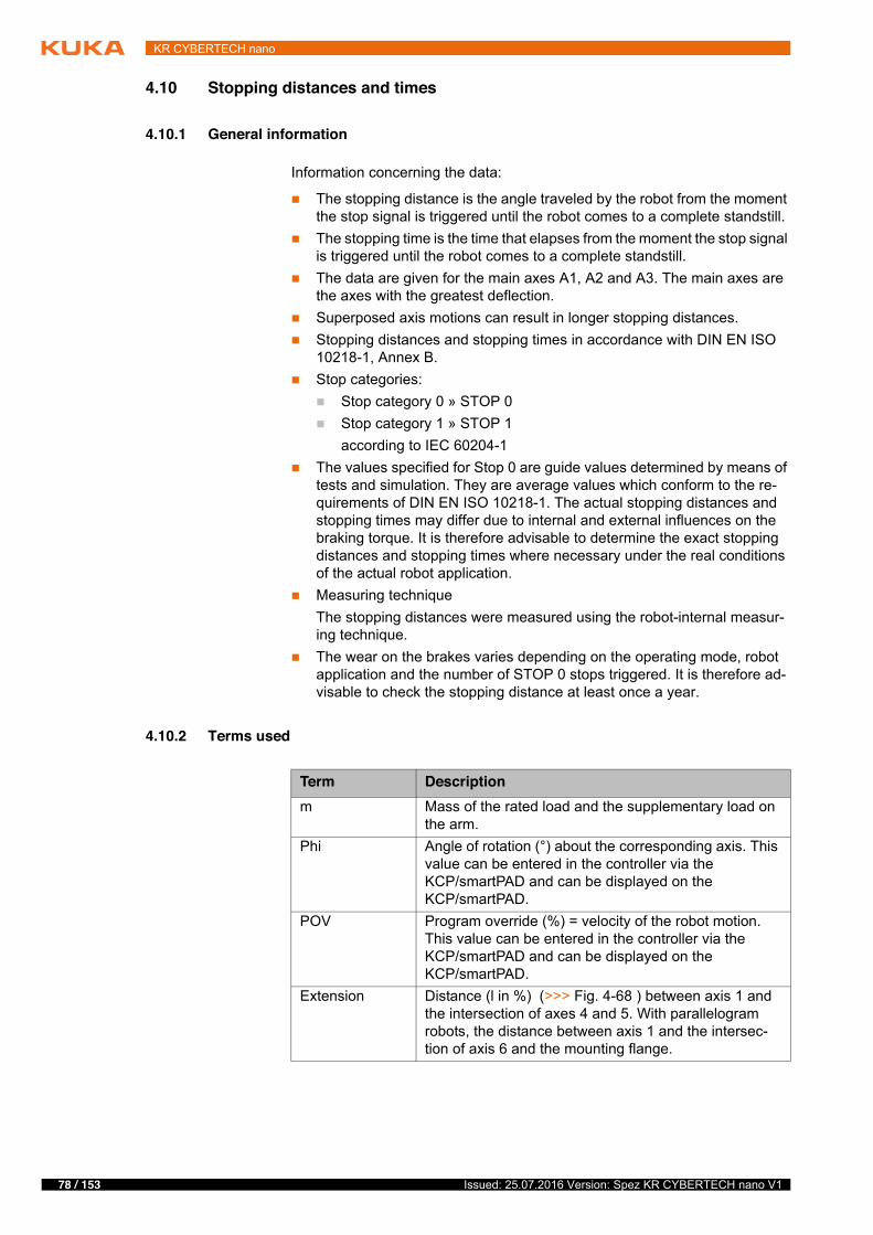
78 / 153 Issued: 25.07.2016 Version: Spez KR CYBERTECH nano V1
KR CYBERTECH nano
4.10 Stopping distances and times
4.10.1 General information
Information concerning the data:
� The stopping distance is the angle traveled by the robot from the moment the stop signal is triggered until the robot comes to a complete standstill.
� The stopping time is the time that elapses from the moment the stop signal is triggered until the robot comes to a complete standstill.
� The data are given for the main axes A1, A2 and A3. The main axes are the axes with the greatest deflection.
� Superposed axis motions can result in longer stopping distances.� Stopping distances and stopping times in accordance with DIN EN ISO
10218-1, Annex B.� Stop categories:
� Stop category 0 » STOP 0 � Stop category 1 » STOP 1
according to IEC 60204-1� The values specified for Stop 0 are guide values determined by means of
tests and simulation. They are average values which conform to the re-quirements of DIN EN ISO 10218-1. The actual stopping distances and stopping times may differ due to internal and external influences on the braking torque. It is therefore advisable to determine the exact stopping distances and stopping times where necessary under the real conditions of the actual robot application.
� Measuring techniqueThe stopping distances were measured using the robot-internal measur-ing technique.
� The wear on the brakes varies depending on the operating mode, robot application and the number of STOP 0 stops triggered. It is therefore ad-visable to check the stopping distance at least once a year.
4.10.2 Terms used
Term Descriptionm Mass of the rated load and the supplementary load on
the arm.Phi Angle of rotation (°) about the corresponding axis. This
value can be entered in the controller via the KCP/smartPAD and can be displayed on the KCP/smartPAD.
POV Program override (%) = velocity of the robot motion. This value can be entered in the controller via the KCP/smartPAD and can be displayed on the KCP/smartPAD.
Extension Distance (l in %) (>>> Fig. 4-68 ) between axis 1 and the intersection of axes 4 and 5. With parallelogram robots, the distance between axis 1 and the intersec-tion of axis 6 and the mounting flange.
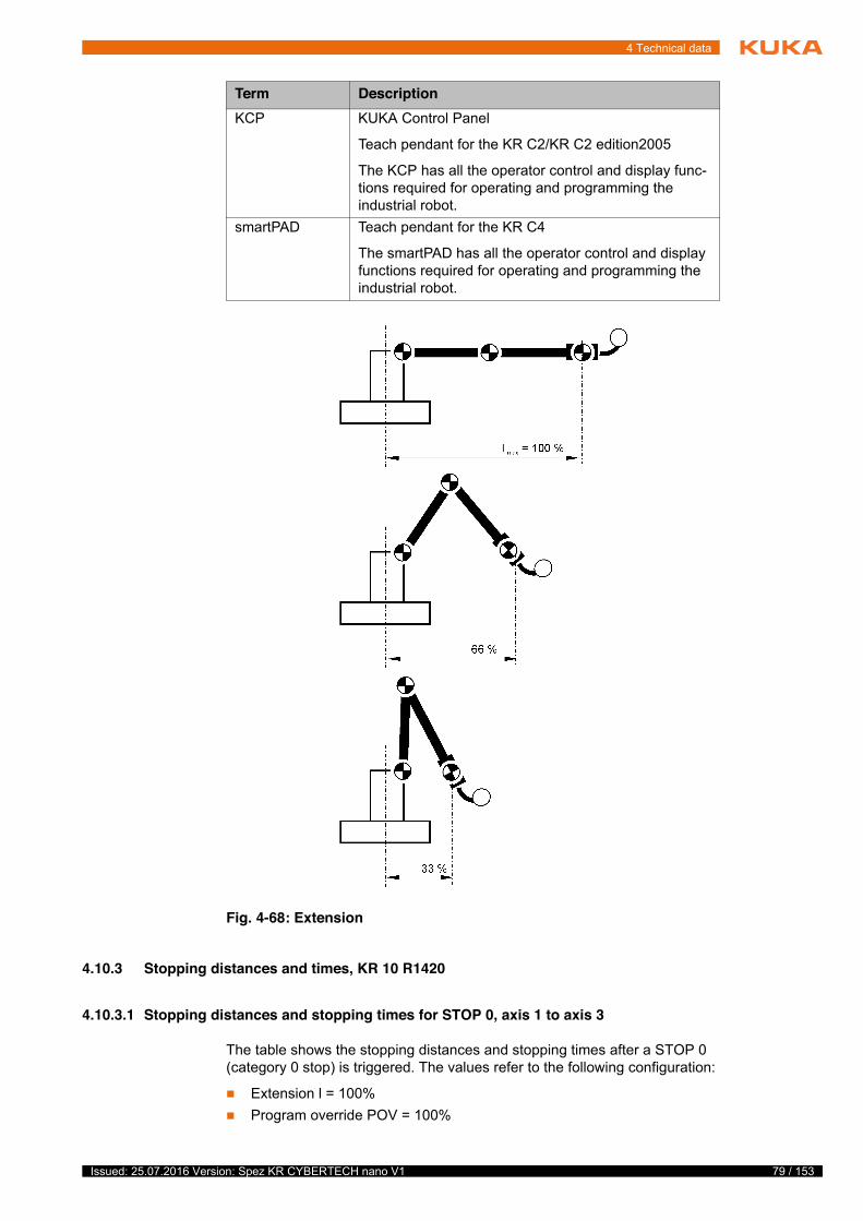
79 / 153Issued: 25.07.2016 Version: Spez KR CYBERTECH nano V1
4 Technical data
4.10.3 Stopping distances and times, KR 10 R1420
4.10.3.1 Stopping distances and stopping times for STOP 0, axis 1 to axis 3
The table shows the stopping distances and stopping times after a STOP 0 (category 0 stop) is triggered. The values refer to the following configuration:
� Extension l = 100%� Program override POV = 100%
KCP KUKA Control Panel
Teach pendant for the KR C2/KR C2 edition2005
The KCP has all the operator control and display func-tions required for operating and programming the industrial robot.
smartPAD Teach pendant for the KR C4
The smartPAD has all the operator control and display functions required for operating and programming the industrial robot.
Fig. 4-68: Extension
Term Description
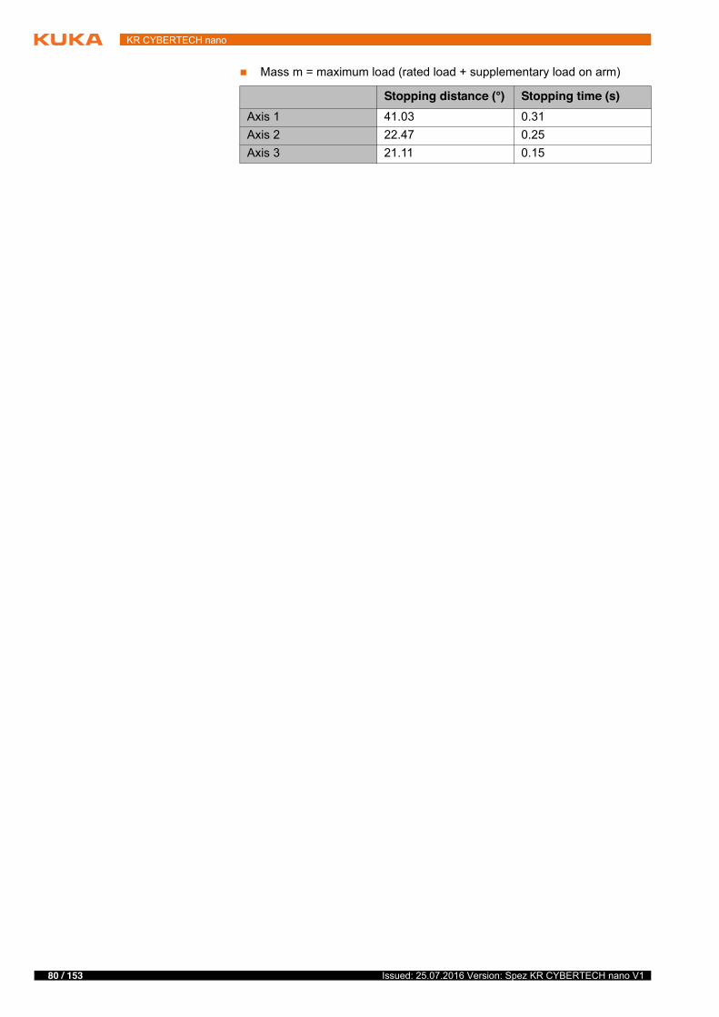
80 / 153 Issued: 25.07.2016 Version: Spez KR CYBERTECH nano V1
KR CYBERTECH nano
� Mass m = maximum load (rated load + supplementary load on arm)
Stopping distance (°) Stopping time (s)Axis 1 41.03 0.31Axis 2 22.47 0.25Axis 3 21.11 0.15
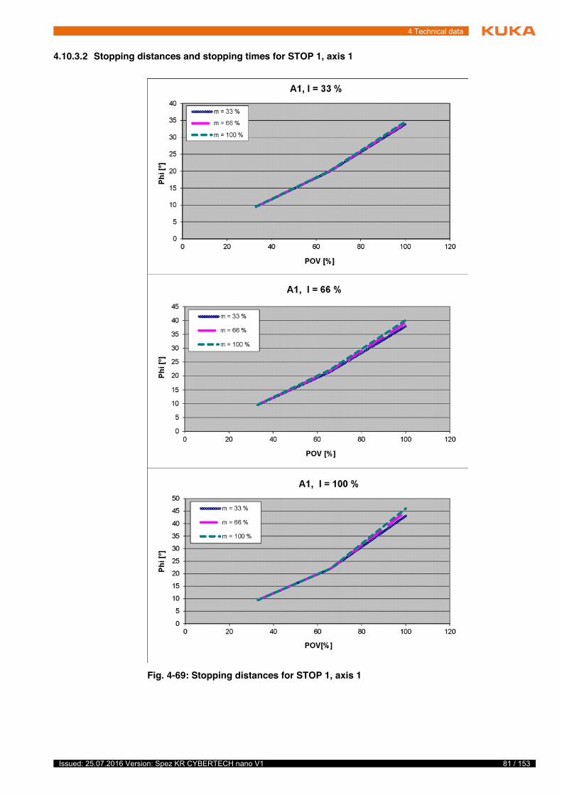
81 / 153Issued: 25.07.2016 Version: Spez KR CYBERTECH nano V1
4 Technical data
4.10.3.2 Stopping distances and stopping times for STOP 1, axis 1
Fig. 4-69: Stopping distances for STOP 1, axis 1
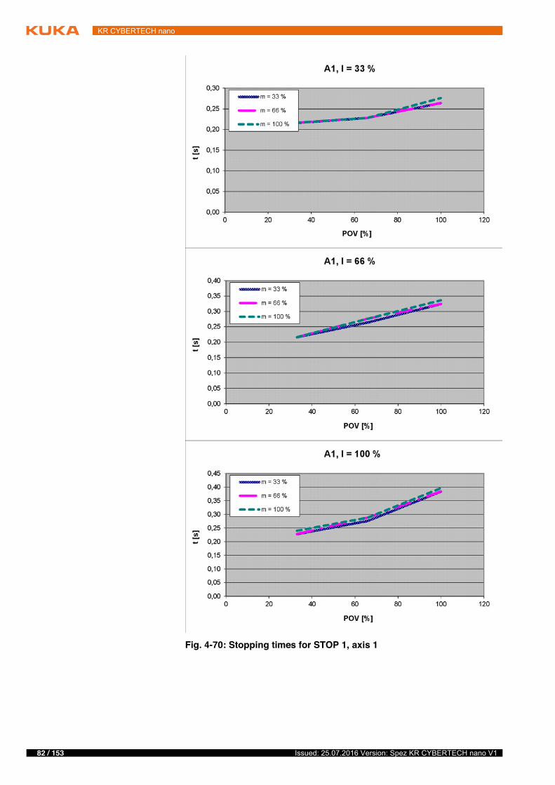
82 / 153 Issued: 25.07.2016 Version: Spez KR CYBERTECH nano V1
KR CYBERTECH nano
Fig. 4-70: Stopping times for STOP 1, axis 1
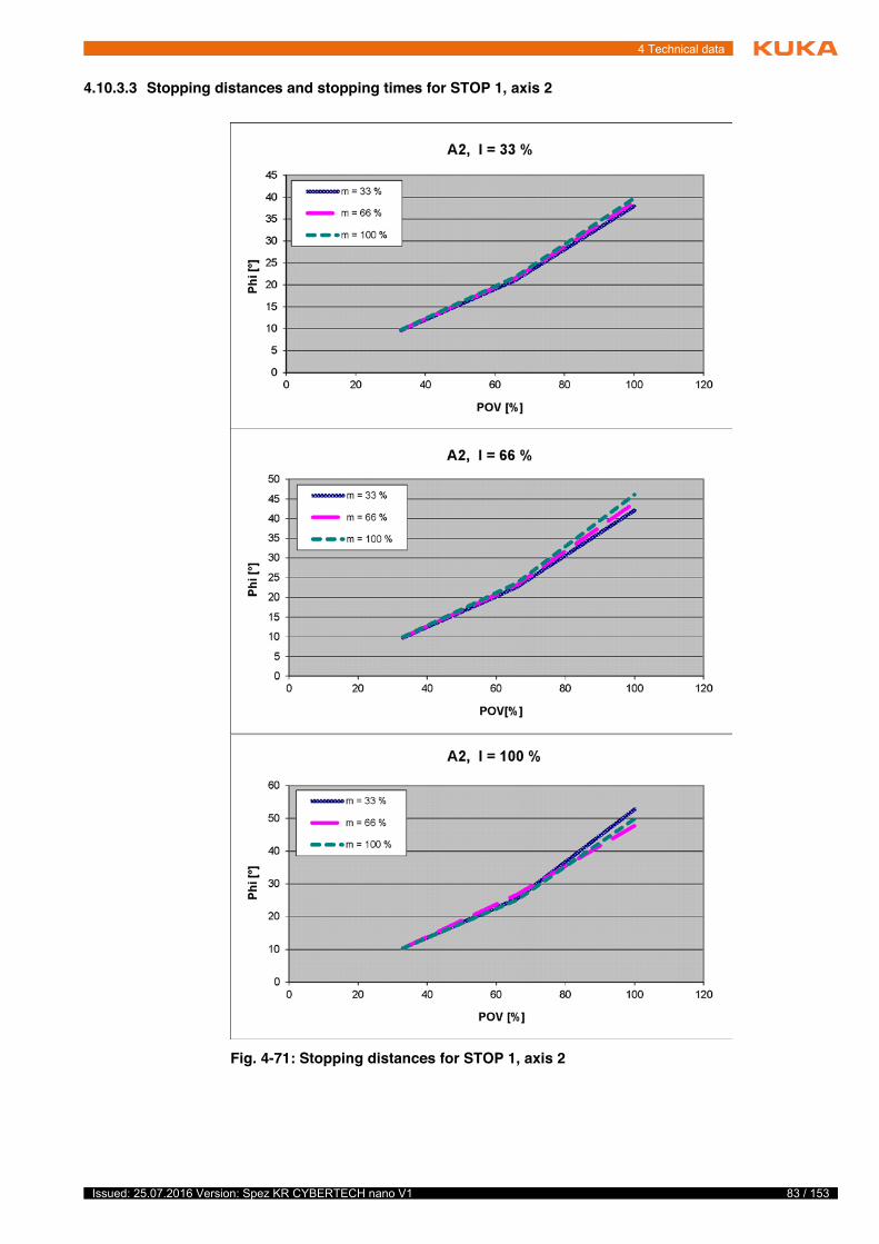
83 / 153Issued: 25.07.2016 Version: Spez KR CYBERTECH nano V1
4 Technical data
4.10.3.3 Stopping distances and stopping times for STOP 1, axis 2
Fig. 4-71: Stopping distances for STOP 1, axis 2
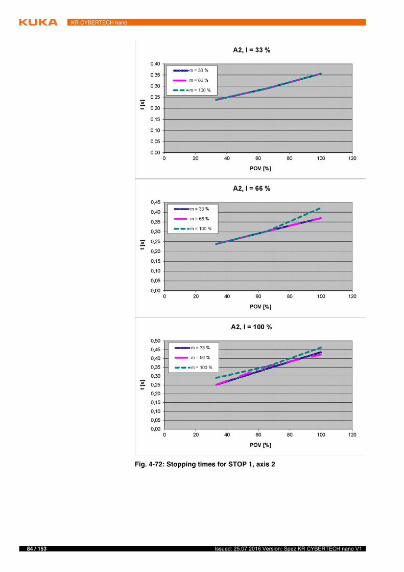
84 / 153 Issued: 25.07.2016 Version: Spez KR CYBERTECH nano V1
KR CYBERTECH nano
Fig. 4-72: Stopping times for STOP 1, axis 2

85 / 153Issued: 25.07.2016 Version: Spez KR CYBERTECH nano V1
4 Technical data
4.10.3.4 Stopping distances and stopping times for STOP 1, axis 3
4.10.4 Stopping distances and times, KR 8 R1620
4.10.4.1 Stopping distances and stopping times for STOP 0, axis 1 to axis 3
The table shows the stopping distances and stopping times after a STOP 0 (category 0 stop) is triggered. The values refer to the following configuration:
� Extension l = 100%� Program override POV = 100%� Mass m = maximum load (rated load + supplementary load on arm)
Fig. 4-73: Stopping distances for STOP 1, axis 3
Fig. 4-74: Stopping times for STOP 1, axis 3
Stopping distance (°) Stopping time (s)Axis 1 54.21 0.40Axis 2 48.89 0.40Axis 3 18.18 0.13
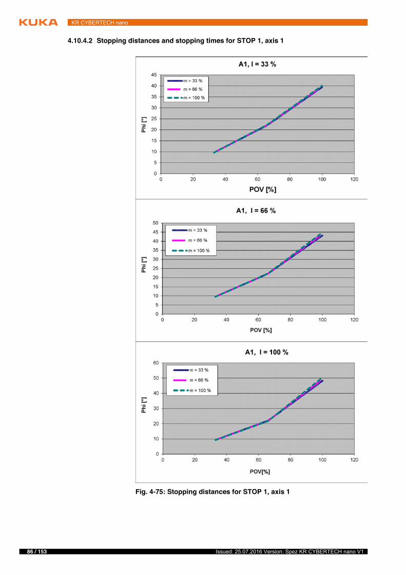
86 / 153 Issued: 25.07.2016 Version: Spez KR CYBERTECH nano V1
KR CYBERTECH nano
4.10.4.2 Stopping distances and stopping times for STOP 1, axis 1
Fig. 4-75: Stopping distances for STOP 1, axis 1
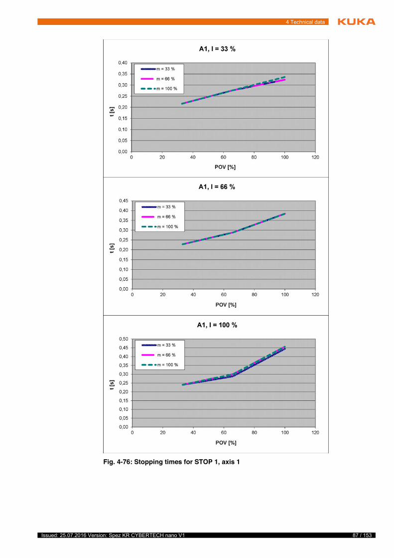
87 / 153Issued: 25.07.2016 Version: Spez KR CYBERTECH nano V1
4 Technical data
Fig. 4-76: Stopping times for STOP 1, axis 1
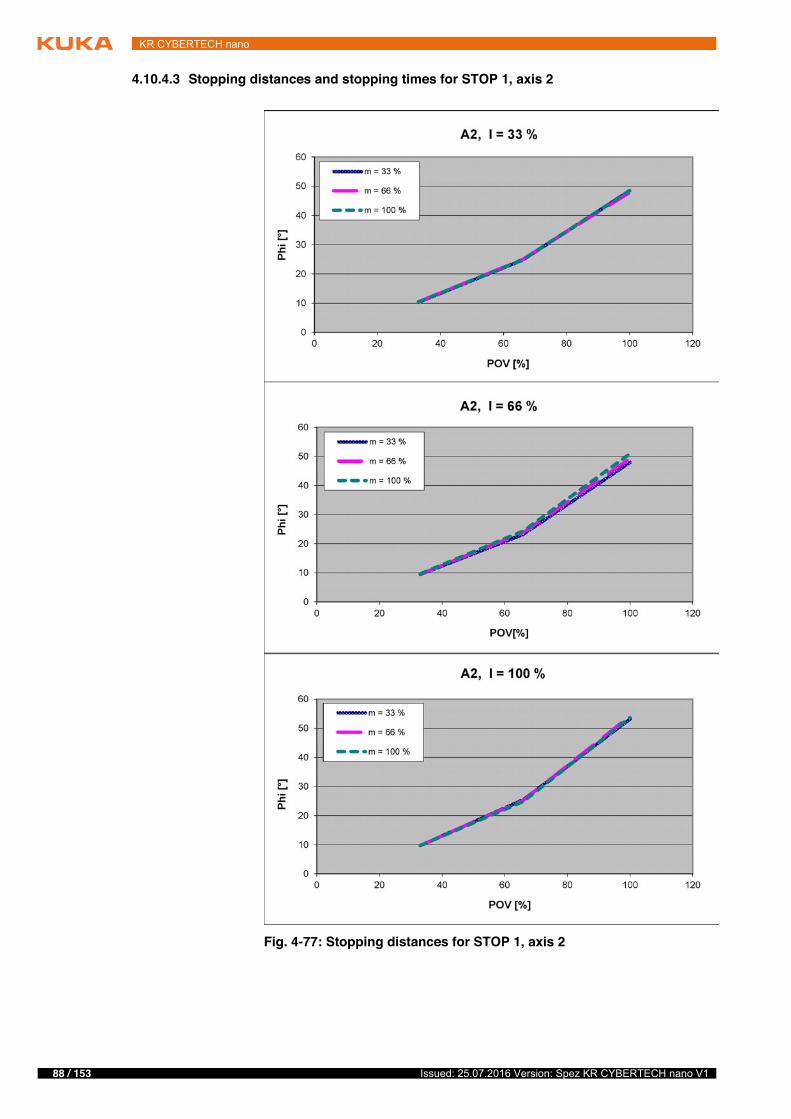
88 / 153 Issued: 25.07.2016 Version: Spez KR CYBERTECH nano V1
KR CYBERTECH nano
4.10.4.3 Stopping distances and stopping times for STOP 1, axis 2
Fig. 4-77: Stopping distances for STOP 1, axis 2
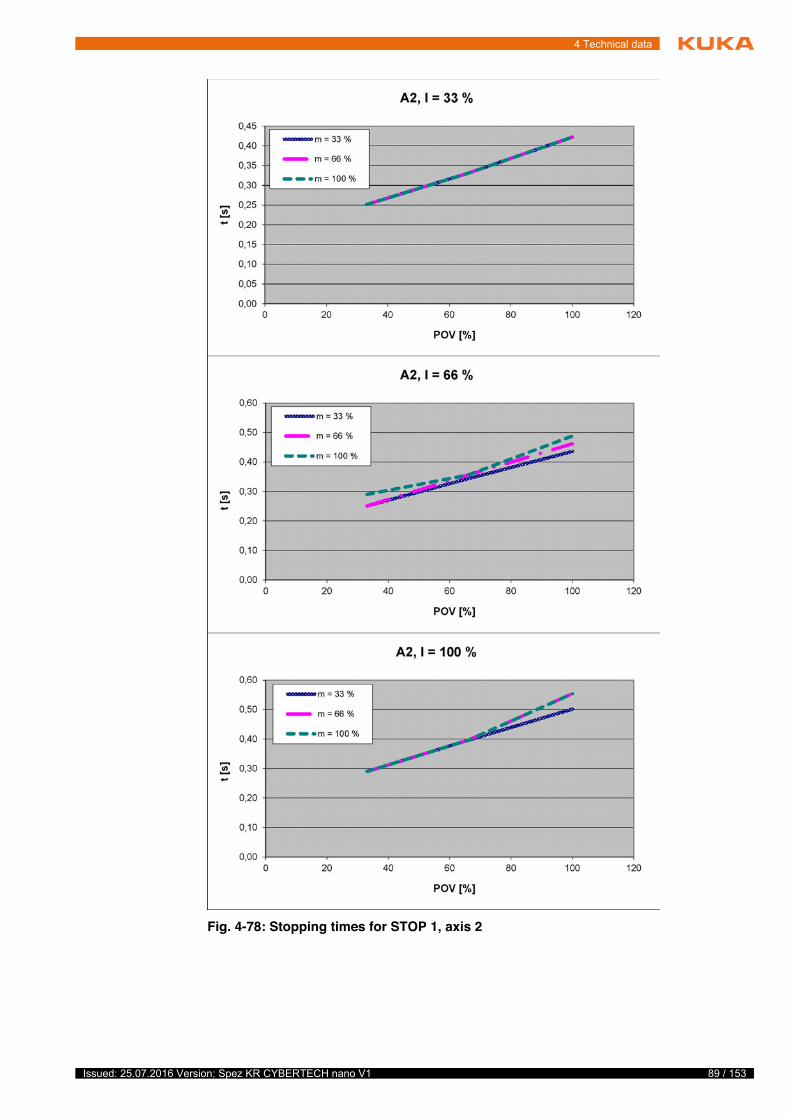
89 / 153Issued: 25.07.2016 Version: Spez KR CYBERTECH nano V1
4 Technical data
Fig. 4-78: Stopping times for STOP 1, axis 2
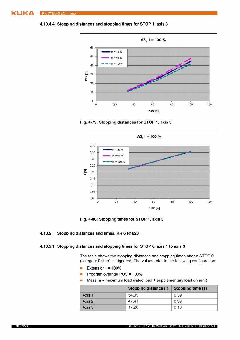
90 / 153 Issued: 25.07.2016 Version: Spez KR CYBERTECH nano V1
KR CYBERTECH nano
4.10.4.4 Stopping distances and stopping times for STOP 1, axis 3
4.10.5 Stopping distances and times, KR 6 R1820
4.10.5.1 Stopping distances and stopping times for STOP 0, axis 1 to axis 3
The table shows the stopping distances and stopping times after a STOP 0 (category 0 stop) is triggered. The values refer to the following configuration:
� Extension l = 100%� Program override POV = 100%� Mass m = maximum load (rated load + supplementary load on arm)
Fig. 4-79: Stopping distances for STOP 1, axis 3
Fig. 4-80: Stopping times for STOP 1, axis 3
Stopping distance (°) Stopping time (s)Axis 1 54.05 0.39Axis 2 47.41 0.39Axis 3 17.26 0.10
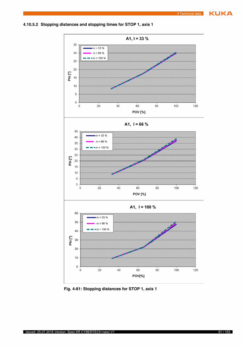
91 / 153Issued: 25.07.2016 Version: Spez KR CYBERTECH nano V1
4 Technical data
4.10.5.2 Stopping distances and stopping times for STOP 1, axis 1
Fig. 4-81: Stopping distances for STOP 1, axis 1
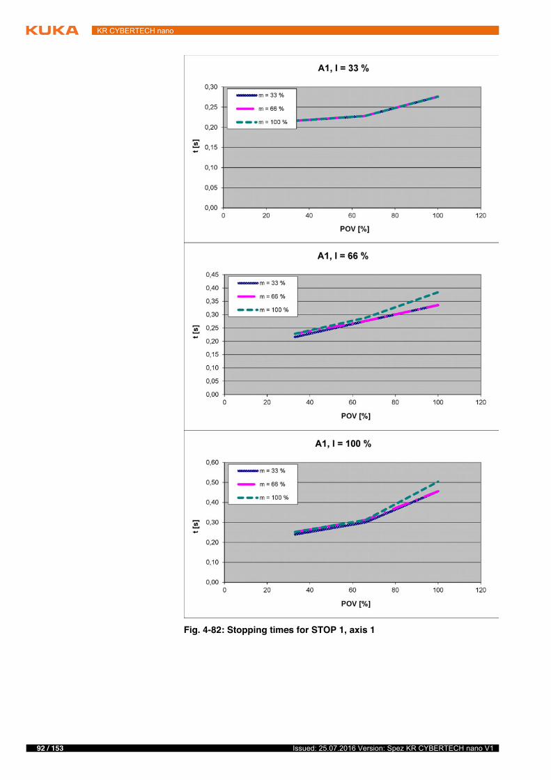
92 / 153 Issued: 25.07.2016 Version: Spez KR CYBERTECH nano V1
KR CYBERTECH nano
Fig. 4-82: Stopping times for STOP 1, axis 1

93 / 153Issued: 25.07.2016 Version: Spez KR CYBERTECH nano V1
4 Technical data
4.10.5.3 Stopping distances and stopping times for STOP 1, axis 2
Fig. 4-83: Stopping distances for STOP 1, axis 2
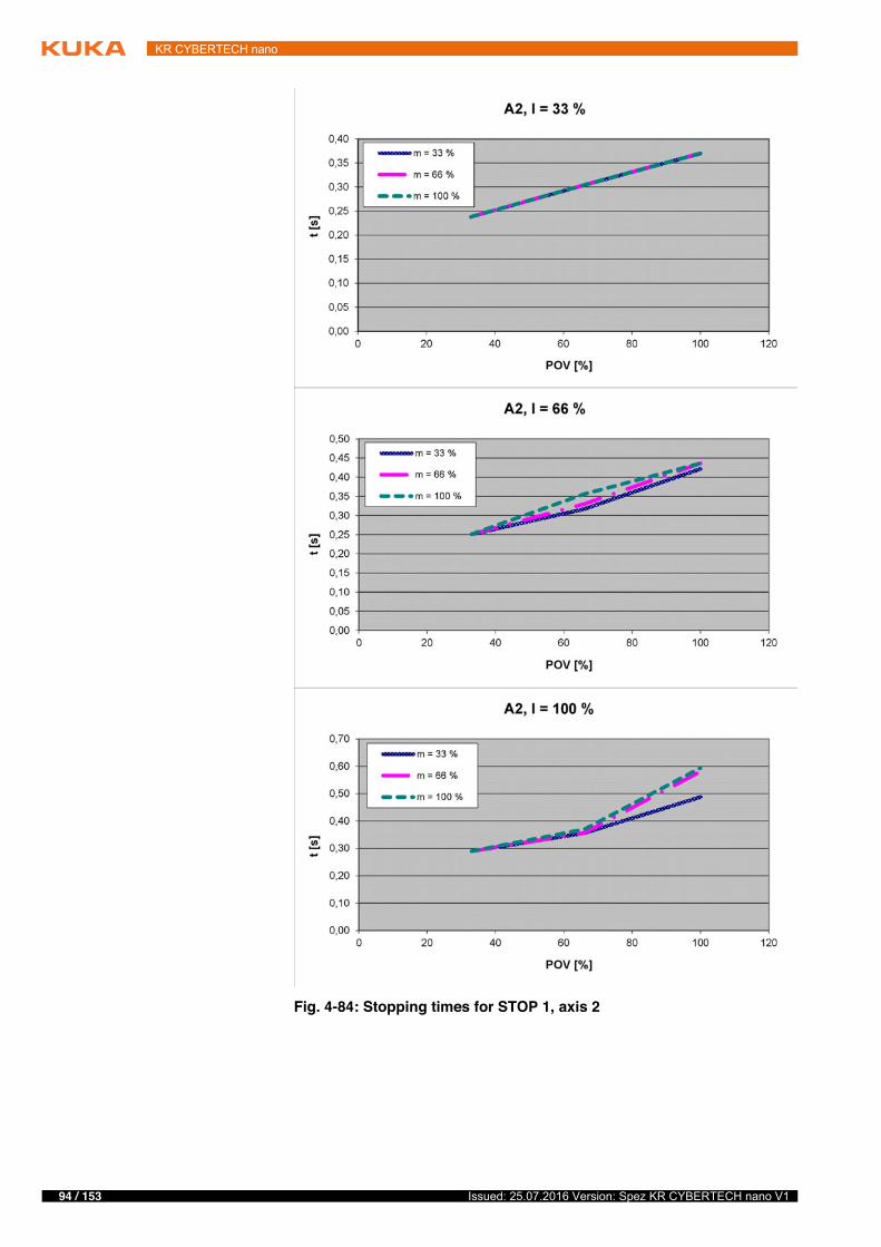
94 / 153 Issued: 25.07.2016 Version: Spez KR CYBERTECH nano V1
KR CYBERTECH nano
Fig. 4-84: Stopping times for STOP 1, axis 2
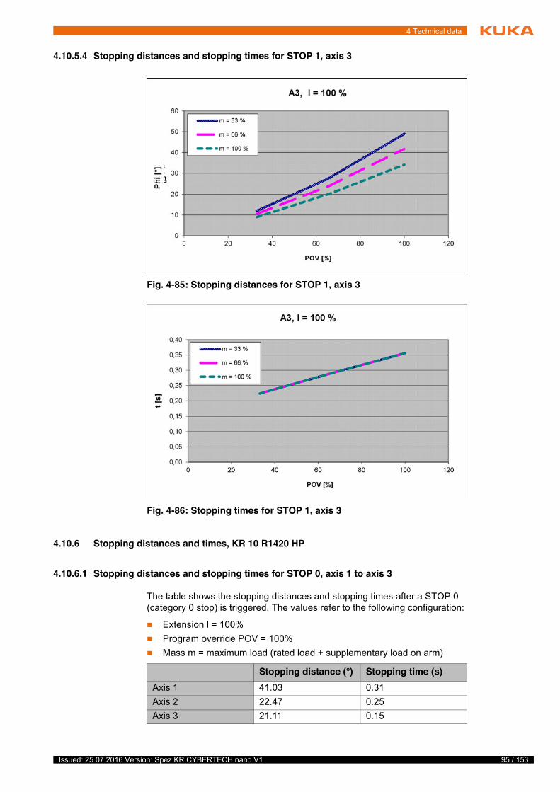
95 / 153Issued: 25.07.2016 Version: Spez KR CYBERTECH nano V1
4 Technical data
4.10.5.4 Stopping distances and stopping times for STOP 1, axis 3
4.10.6 Stopping distances and times, KR 10 R1420 HP
4.10.6.1 Stopping distances and stopping times for STOP 0, axis 1 to axis 3
The table shows the stopping distances and stopping times after a STOP 0 (category 0 stop) is triggered. The values refer to the following configuration:
� Extension l = 100%� Program override POV = 100%� Mass m = maximum load (rated load + supplementary load on arm)
Fig. 4-85: Stopping distances for STOP 1, axis 3
Fig. 4-86: Stopping times for STOP 1, axis 3
Stopping distance (°) Stopping time (s)Axis 1 41.03 0.31Axis 2 22.47 0.25Axis 3 21.11 0.15
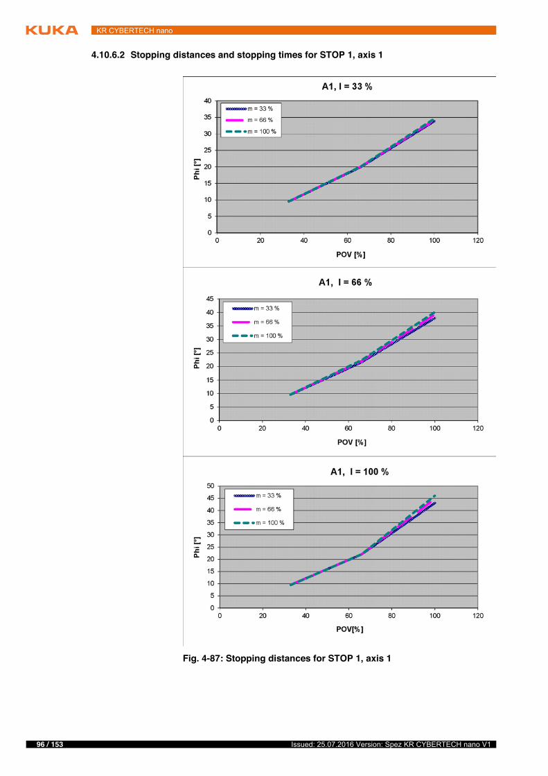
96 / 153 Issued: 25.07.2016 Version: Spez KR CYBERTECH nano V1
KR CYBERTECH nano
4.10.6.2 Stopping distances and stopping times for STOP 1, axis 1
Fig. 4-87: Stopping distances for STOP 1, axis 1
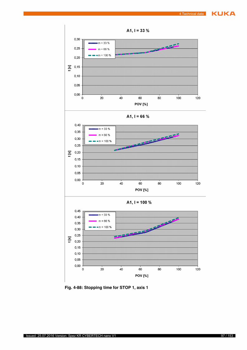
97 / 153Issued: 25.07.2016 Version: Spez KR CYBERTECH nano V1
4 Technical data
Fig. 4-88: Stopping time for STOP 1, axis 1
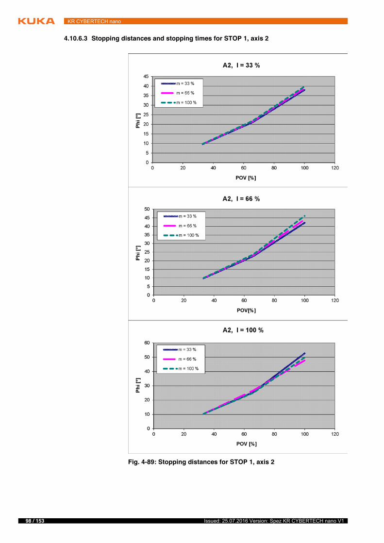
98 / 153 Issued: 25.07.2016 Version: Spez KR CYBERTECH nano V1
KR CYBERTECH nano
4.10.6.3 Stopping distances and stopping times for STOP 1, axis 2
Fig. 4-89: Stopping distances for STOP 1, axis 2
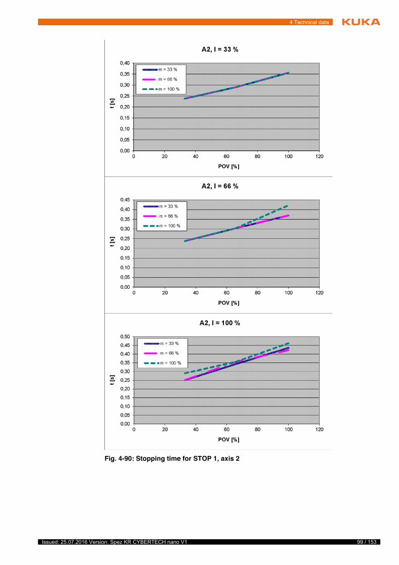
99 / 153Issued: 25.07.2016 Version: Spez KR CYBERTECH nano V1
4 Technical data
Fig. 4-90: Stopping time for STOP 1, axis 2
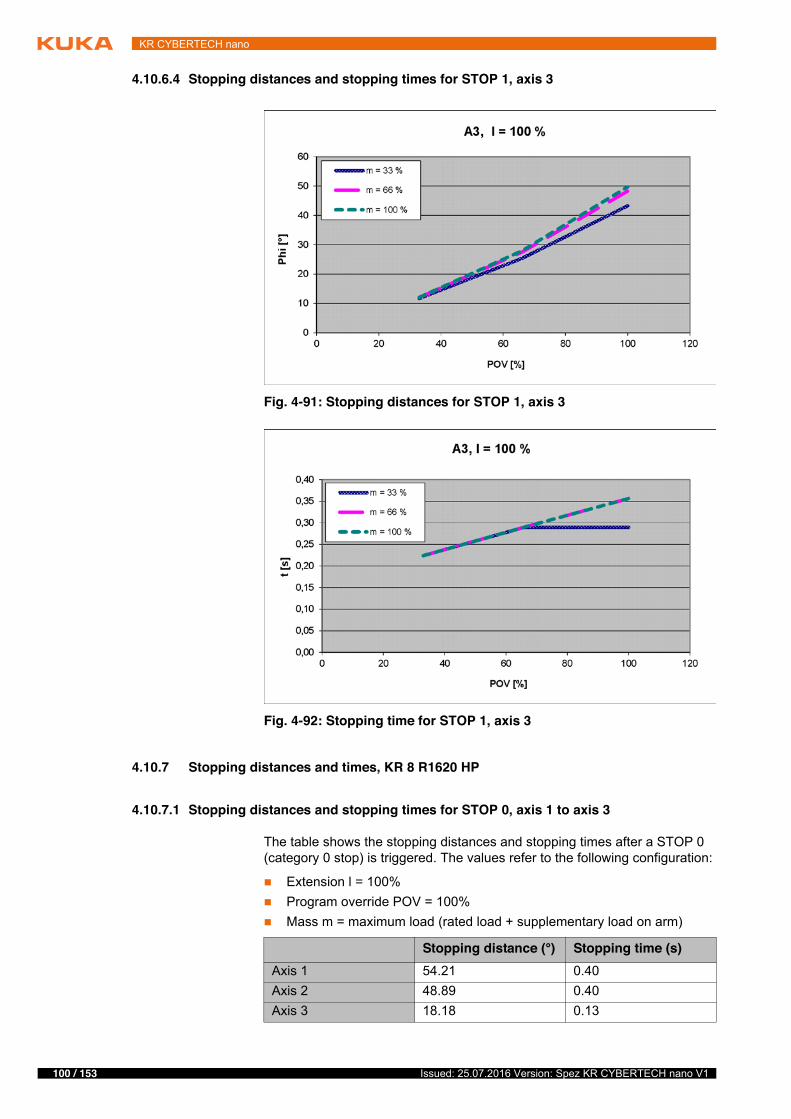
100 / 153 Issued: 25.07.2016 Version: Spez KR CYBERTECH nano V1
KR CYBERTECH nano
4.10.6.4 Stopping distances and stopping times for STOP 1, axis 3
4.10.7 Stopping distances and times, KR 8 R1620 HP
4.10.7.1 Stopping distances and stopping times for STOP 0, axis 1 to axis 3
The table shows the stopping distances and stopping times after a STOP 0 (category 0 stop) is triggered. The values refer to the following configuration:
� Extension l = 100%� Program override POV = 100%� Mass m = maximum load (rated load + supplementary load on arm)
Fig. 4-91: Stopping distances for STOP 1, axis 3
Fig. 4-92: Stopping time for STOP 1, axis 3
Stopping distance (°) Stopping time (s)Axis 1 54.21 0.40Axis 2 48.89 0.40Axis 3 18.18 0.13
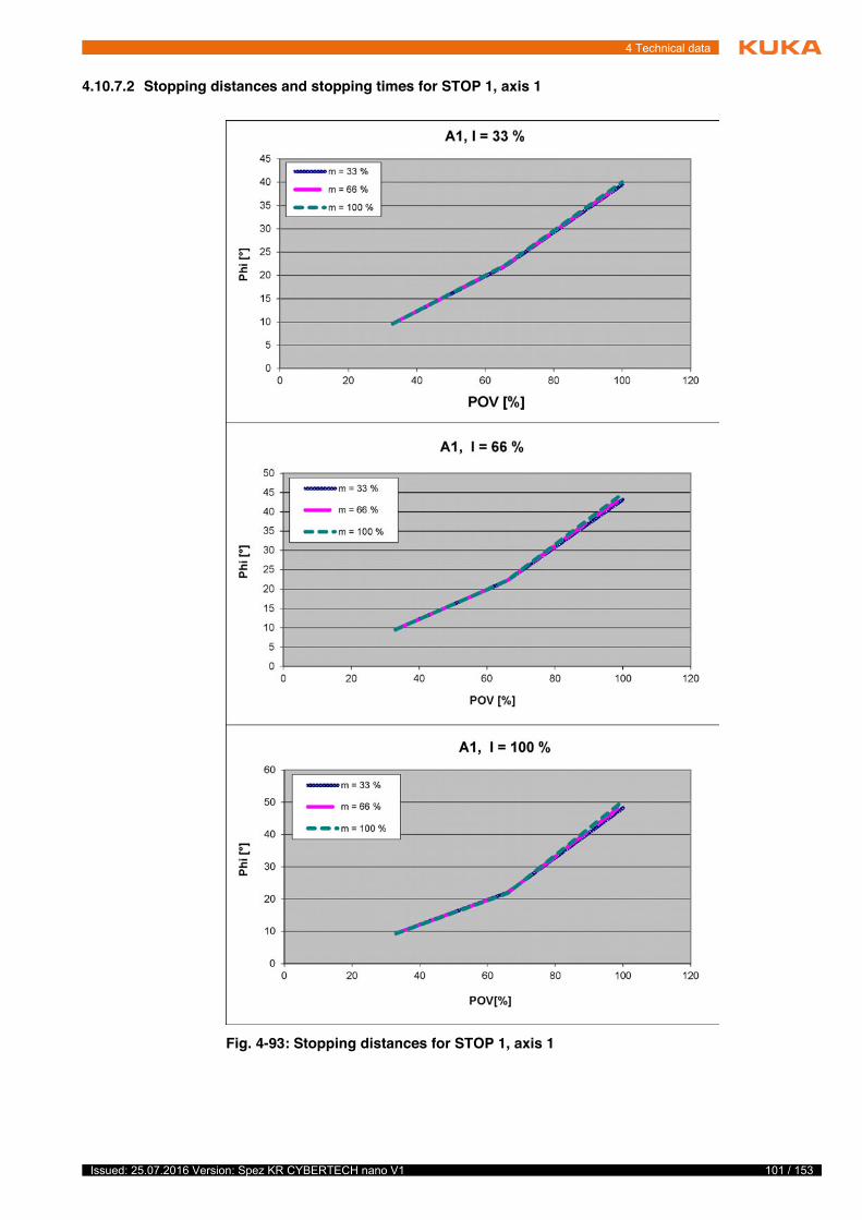
101 / 153Issued: 25.07.2016 Version: Spez KR CYBERTECH nano V1
4 Technical data
4.10.7.2 Stopping distances and stopping times for STOP 1, axis 1
Fig. 4-93: Stopping distances for STOP 1, axis 1
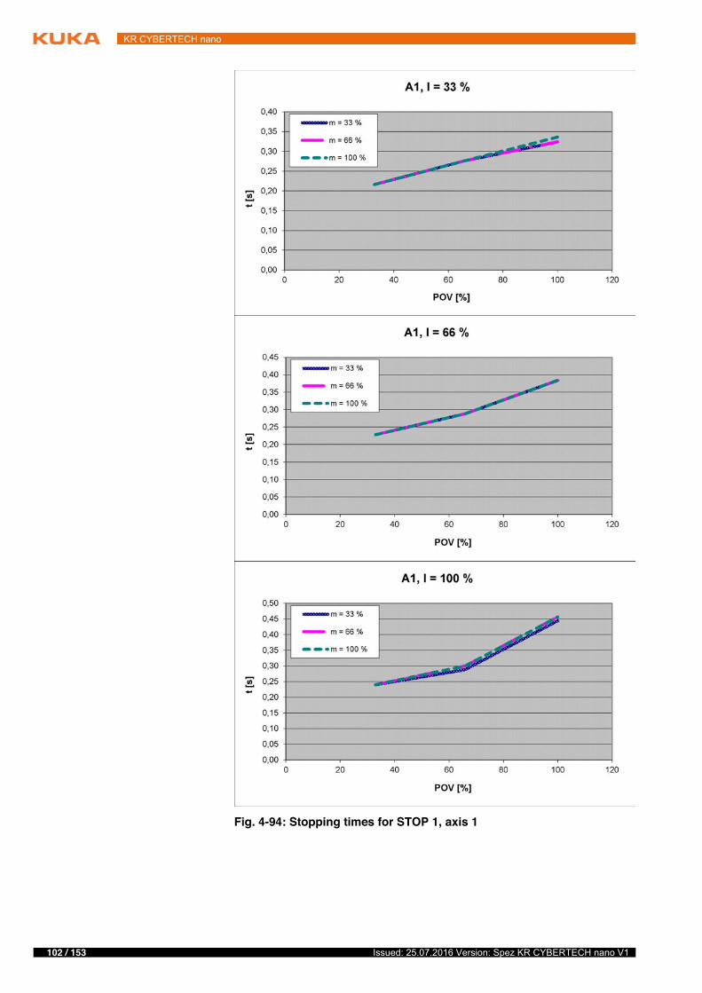
102 / 153 Issued: 25.07.2016 Version: Spez KR CYBERTECH nano V1
KR CYBERTECH nano
Fig. 4-94: Stopping times for STOP 1, axis 1
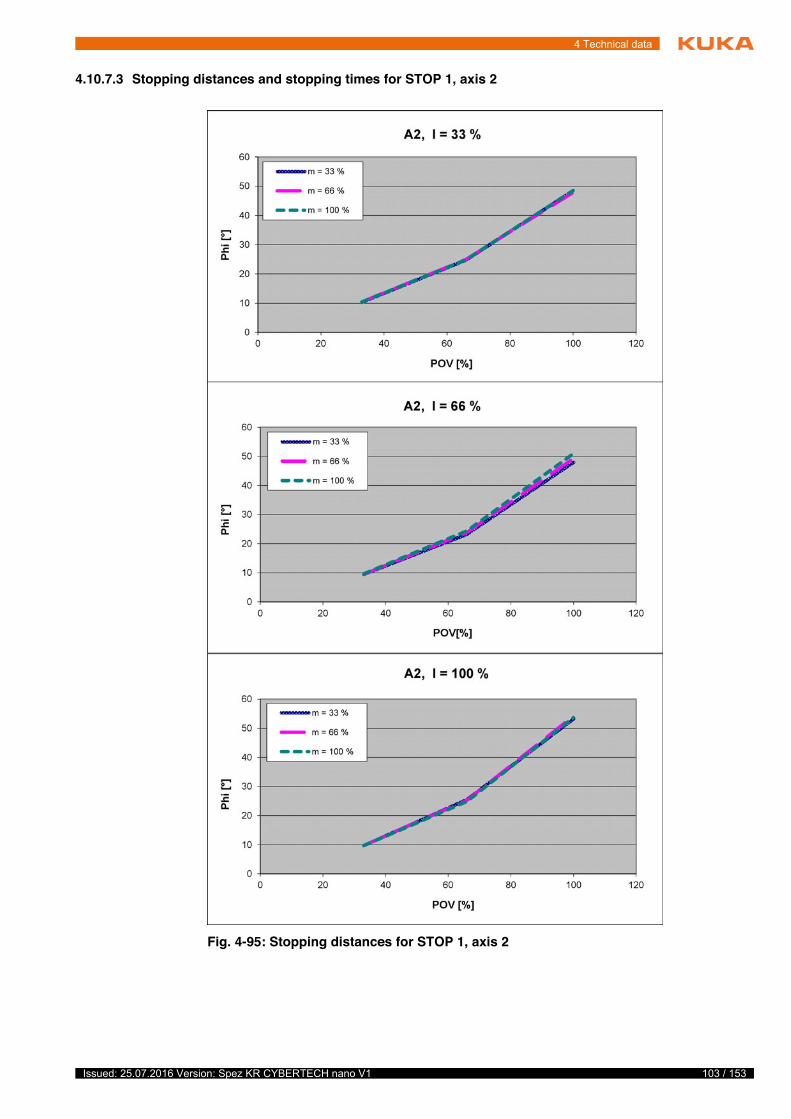
103 / 153Issued: 25.07.2016 Version: Spez KR CYBERTECH nano V1
4 Technical data
4.10.7.3 Stopping distances and stopping times for STOP 1, axis 2
Fig. 4-95: Stopping distances for STOP 1, axis 2
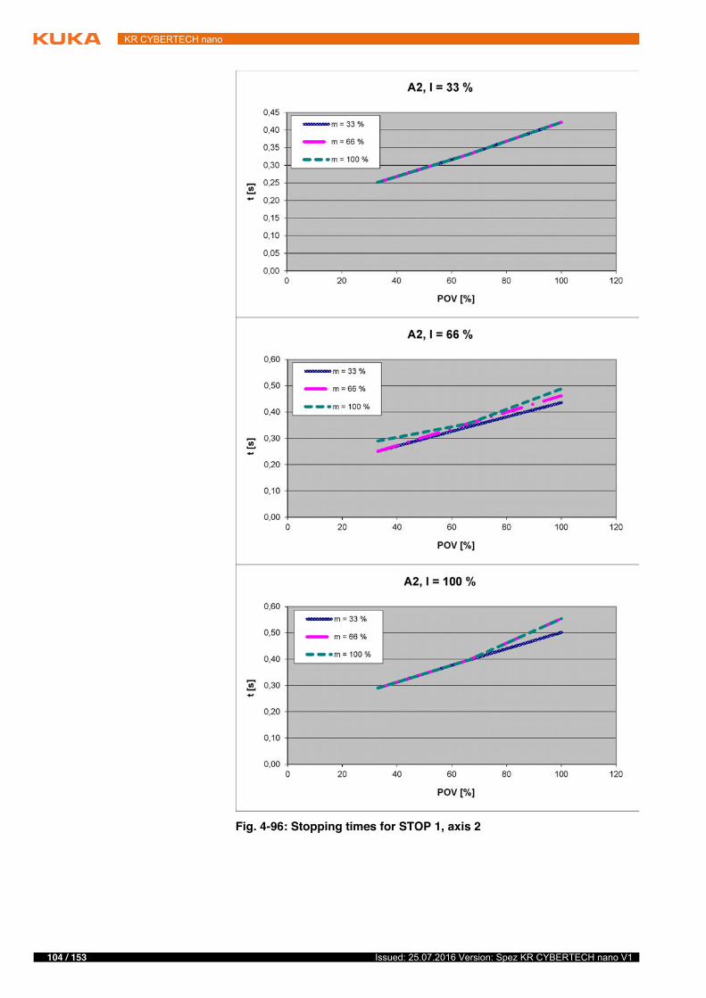
104 / 153 Issued: 25.07.2016 Version: Spez KR CYBERTECH nano V1
KR CYBERTECH nano
Fig. 4-96: Stopping times for STOP 1, axis 2

105 / 153Issued: 25.07.2016 Version: Spez KR CYBERTECH nano V1
4 Technical data
4.10.7.4 Stopping distances and stopping times for STOP 1, axis 3
4.10.8 Stopping distances and times, KR 6 R1820 HP
4.10.8.1 Stopping distances and stopping times for STOP 0, axis 1 to axis 3
The table shows the stopping distances and stopping times after a STOP 0 (category 0 stop) is triggered. The values refer to the following configuration:
� Extension l = 100%� Program override POV = 100%� Mass m = maximum load (rated load + supplementary load on arm)
Fig. 4-97: Stopping distances for STOP 1, axis 3
Fig. 4-98: Stopping times for STOP 1, axis 3
Stopping distance (°) Stopping time (s)Axis 1 54.05 0.39Axis 2 47.41 0.39Axis 3 17.26 0.10
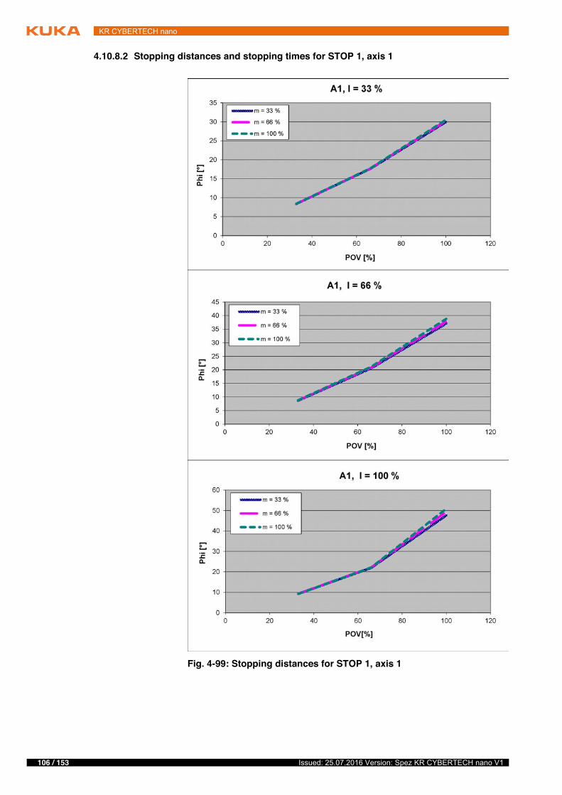
106 / 153 Issued: 25.07.2016 Version: Spez KR CYBERTECH nano V1
KR CYBERTECH nano
4.10.8.2 Stopping distances and stopping times for STOP 1, axis 1
Fig. 4-99: Stopping distances for STOP 1, axis 1

107 / 153Issued: 25.07.2016 Version: Spez KR CYBERTECH nano V1
4 Technical data
Fig. 4-100: Stopping times for STOP 1, axis 1
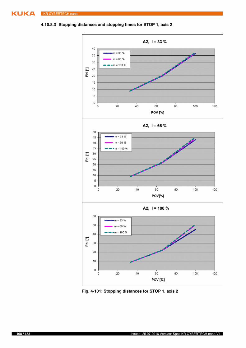
108 / 153 Issued: 25.07.2016 Version: Spez KR CYBERTECH nano V1
KR CYBERTECH nano
4.10.8.3 Stopping distances and stopping times for STOP 1, axis 2
Fig. 4-101: Stopping distances for STOP 1, axis 2
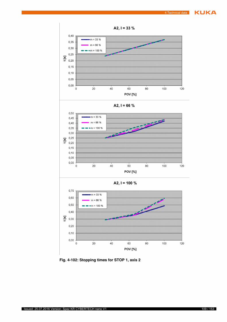
109 / 153Issued: 25.07.2016 Version: Spez KR CYBERTECH nano V1
4 Technical data
Fig. 4-102: Stopping times for STOP 1, axis 2
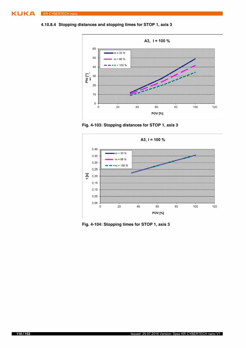
110 / 153 Issued: 25.07.2016 Version: Spez KR CYBERTECH nano V1
KR CYBERTECH nano
4.10.8.4 Stopping distances and stopping times for STOP 1, axis 3
Fig. 4-103: Stopping distances for STOP 1, axis 3
Fig. 4-104: Stopping times for STOP 1, axis 3
111 / 153Issued: 25.07.2016 Version: Spez KR CYBERTECH nano V1
5 Safety
5 Safety
5.1 General
5.1.1 Liability
The device described in this document is either an industrial robot or a com-ponent thereof.
Components of the industrial robot:
� Manipulator� Robot controller� Teach pendant� Connecting cables� External axes (optional)
e.g. linear unit, turn-tilt table, positioner� Software� Options, accessories
The industrial robot is built using state-of-the-art technology and in accor-dance with the recognized safety rules. Nevertheless, misuse of the industrial robot may constitute a risk to life and limb or cause damage to the industrial robot and to other material property.
The industrial robot may only be used in perfect technical condition in accor-dance with its designated use and only by safety-conscious persons who are fully aware of the risks involved in its operation. Use of the industrial robot is subject to compliance with this document and with the declaration of incorpo-ration supplied together with the industrial robot. Any functional disorders af-fecting safety must be rectified immediately.
Safety infor-mation
Safety information cannot be held against KUKA Roboter GmbH. Even if all safety instructions are followed, this is not a guarantee that the industrial robot will not cause personal injuries or material damage.
No modifications may be carried out to the industrial robot without the autho-rization of KUKA Roboter GmbH. Additional components (tools, software, etc.), not supplied by KUKA Roboter GmbH, may be integrated into the indus-trial robot. The user is liable for any damage these components may cause to the industrial robot or to other material property.
In addition to the Safety chapter, this document contains further safety instruc-tions. These must also be observed.
f
t
y
�This “Safety” chapter refers to a mechanical component of an indus-trial robot.�If the mechanical component is used together with a KUKA robot
controller, the “Safety” chapter of the operating instructions or assembly instructions of the robot controller must be used!This contains all the information provided in this “Safety” chapter. It also contains additional safety information relating to the robot controller which must be observed.
� Where this “Safety” chapter uses the term “industrial robot”, this also re-fers to the individual mechanical component if applicable.
112 / 153 Issued: 25.07.2016 Version: Spez KR CYBERTECH nano V1
KR CYBERTECH nano
5.1.2 Intended use of the industrial robot
The industrial robot is intended exclusively for the use designated in the “Pur-pose” chapter of the operating instructions or assembly instructions.
Any use or application deviating from the intended use is deemed to be misuse and is not allowed. The manufacturer is not liable for any damage resulting from such misuse. The risk lies entirely with the user.
Operation of the industrial robot in accordance with its intended use also re-quires compliance with the operating and assembly instructions for the individ-ual components, with particular reference to the maintenance specifications.
Misuse Any use or application deviating from the intended use is deemed to be misuse and is not allowed. This includes e.g.:
� Transportation of persons and animals� Use as a climbing aid� Operation outside the specified operating parameters� Use in potentially explosive environments� Operation without additional safeguards� Outdoor operation� Underground operation
5.1.3 EC declaration of conformity and declaration of incorporation
The industrial robot constitutes partly completed machinery as defined by the EC Machinery Directive. The industrial robot may only be put into operation if the following preconditions are met:
� The industrial robot is integrated into a complete system.or: The industrial robot, together with other machinery, constitutes a com-plete system.or: All safety functions and safeguards required for operation in the com-plete machine as defined by the EC Machinery Directive have been added to the industrial robot.
� The complete system complies with the EC Machinery Directive. This has been confirmed by means of an assessment of conformity.
Declaration of conformity
The system integrator must issue a declaration of conformity for the complete system in accordance with the Machinery Directive. The declaration of confor-mity forms the basis for the CE mark for the system. The industrial robot must always be operated in accordance with the applicable national laws, regula-tions and standards.
The robot controller has a CE mark in accordance with the EMC Directive and the Low Voltage Directive.
Declaration of incorporation
The partly completed machinery is supplied with a declaration of incorporation in accordance with Annex II B of the EC Machinery Directive 2006/42/EC. The assembly instructions and a list of essential requirements complied with in ac-cordance with Annex I are integral parts of this declaration of incorporation.
The declaration of incorporation declares that the start-up of the partly com-pleted machinery is not allowed until the partly completed machinery has been incorporated into machinery, or has been assembled with other parts to form machinery, and this machinery complies with the terms of the EC Machinery Directive, and the EC declaration of conformity is present in accordance with Annex II A.
113 / 153Issued: 25.07.2016 Version: Spez KR CYBERTECH nano V1
5 Safety
5.1.4 Terms used
5.2 Personnel
The following persons or groups of persons are defined for the industrial robot:
� User
Term DescriptionAxis range Range of each axis, in degrees or millimeters, within which it may move.
The axis range must be defined for each axis.Stopping distance Stopping distance = reaction distance + braking distance
The stopping distance is part of the danger zone.Workspace The manipulator is allowed to move within its workspace. The work-
space is derived from the individual axis ranges.Operator(User)
The user of the industrial robot can be the management, employer or delegated person responsible for use of the industrial robot.
Danger zone The danger zone consists of the workspace and the stopping distances.Service life The service life of a safety-relevant component begins at the time of
delivery of the component to the customer.
The service life is not affected by whether the component is used in a robot controller or elsewhere or not, as safety-relevant components are also subject to aging during storage.
KCP KUKA Control Panel
Teach pendant for the KR C2/KR C2 edition2005
The KCP has all the operator control and display functions required for operating and programming the industrial robot.
KUKA smartPAD see “smartPAD”Manipulator The robot arm and the associated electrical installationsSafety zone The safety zone is situated outside the danger zone.smartPAD Teach pendant for the KR C4
The smartPAD has all the operator control and display functions required for operating and programming the industrial robot.
Stop category 0 The drives are deactivated immediately and the brakes are applied. The manipulator and any external axes (optional) perform path-oriented braking.
Note: This stop category is called STOP 0 in this document.Stop category 1 The manipulator and any external axes (optional) perform path-main-
taining braking. The drives are deactivated after 1 s and the brakes are applied.
Note: This stop category is called STOP 1 in this document.Stop category 2 The drives are not deactivated and the brakes are not applied. The
manipulator and any external axes (optional) are braked with a normal braking ramp.
Note: This stop category is called STOP 2 in this document.System integrator(plant integrator)
System integrators are people who safely integrate the industrial robot into a complete system and commission it.
T1 Test mode, Manual Reduced Velocity (<= 250 mm/s)T2 Test mode, Manual High Velocity (> 250 mm/s permissible)External axis Motion axis which is not part of the manipulator but which is controlled
using the robot controller, e.g. KUKA linear unit, turn-tilt table, Posiflex.
114 / 153 Issued: 25.07.2016 Version: Spez KR CYBERTECH nano V1
KR CYBERTECH nano
� Personnel
User The user must observe the labor laws and regulations. This includes e.g.:
� The user must comply with his monitoring obligations.� The user must carry out briefing at defined intervals.
Personnel Personnel must be instructed, before any work is commenced, in the type of work involved and what exactly it entails as well as any hazards which may ex-ist. Instruction must be carried out regularly. Instruction is also required after particular incidents or technical modifications.
Personnel includes:
� System integrator� Operators, subdivided into:
� Start-up, maintenance and service personnel� Operating personnel� Cleaning personnel
System integrator The industrial robot is safely integrated into a complete system by the system integrator.
The system integrator is responsible for the following tasks:
� Installing the industrial robot� Connecting the industrial robot� Performing risk assessment� Implementing the required safety functions and safeguards� Issuing the declaration of conformity� Attaching the CE mark� Creating the operating instructions for the complete system
Operator The operator must meet the following preconditions:
� The operator must be trained for the work to be carried out.� Work on the industrial robot must only be carried out by qualified person-
nel. These are people who, due to their specialist training, knowledge and experience, and their familiarization with the relevant standards, are able to assess the work to be carried out and detect any potential hazards.
5.3 Workspace, safety zone and danger zone
Workspaces are to be restricted to the necessary minimum size. A workspace must be safeguarded using appropriate safeguards.
All persons working with the industrial robot must have read and un-derstood the industrial robot documentation, including the safety chapter.
Installation, exchange, adjustment, operation, maintenance and re-pair must be performed only as specified in the operating or assembly instructions for the relevant component of the industrial robot and only
by personnel specially trained for this purpose.
Work on the electrical and mechanical equipment of the industrial ro-bot may only be carried out by specially trained personnel.
115 / 153Issued: 25.07.2016 Version: Spez KR CYBERTECH nano V1
5 Safety
The safeguards (e.g. safety gate) must be situated inside the safety zone. In the case of a stop, the manipulator and external axes (optional) are braked and come to a stop within the danger zone.
The danger zone consists of the workspace and the stopping distances of the manipulator and external axes (optional). It must be safeguarded by means of physical safeguards to prevent danger to persons or the risk of material dam-age.
5.4 Overview of protective equipment
The protective equipment of the mechanical component may include:
� Mechanical end stops� Mechanical axis range limitation (optional)� Axis range monitoring (optional)� Release device (optional)� Labeling of danger areas
Not all equipment is relevant for every mechanical component.
5.4.1 Mechanical end stops
Depending on the robot variant, the axis ranges of the main and wrist axes of the manipulator are partially limited by mechanical end stops.
Additional mechanical end stops can be installed on the external axes.
5.4.2 Mechanical axis range limitation (optional)
Some manipulators can be fitted with mechanical axis range limitation in axes A1 to A3. The adjustable axis range limitation systems restrict the working range to the required minimum. This increases personal safety and protection of the system.
In the case of manipulators that are not designed to be fitted with mechanical axis range limitation, the workspace must be laid out in such a way that there is no danger to persons or material property, even in the absence of mechan-ical axis range limitation.
If this is not possible, the workspace must be limited by means of photoelectric barriers, photoelectric curtains or obstacles on the system side. There must be no shearing or crushing hazards at the loading and transfer areas.
5.4.3 Axis range monitoring (optional)
Some manipulators can be fitted with dual-channel axis range monitoring sys-tems in main axes A1 to A3. The positioner axes may be fitted with additional axis range monitoring systems. The safety zone for an axis can be adjusted
If the manipulator or an external axis hits an obstruction or a mechanical end stop or axis range limitation, the ma-
nipulator can no longer be operated safely. The manipulator must be taken out of operation and KUKA Roboter GmbH must be consulted before it is put back into operation .
This option is not available for all robot models. Information on spe-cific robot models can be obtained from KUKA Roboter GmbH.
116 / 153 Issued: 25.07.2016 Version: Spez KR CYBERTECH nano V1
KR CYBERTECH nano
and monitored using an axis range monitoring system. This increases person-al safety and protection of the system.
5.4.4 Options for moving the manipulator without drive energy
Description The following options are available for moving the manipulator without drive energy after an accident or malfunction:
� Release device (optional)The release device can be used for the main axis drive motors and, de-pending on the robot variant, also for the wrist axis drive motors.
� Brake release device (option)The brake release device is designed for robot variants whose motors are not freely accessible.
� Moving the wrist axes directly by handThere is no release device available for the wrist axes of variants in the low payload category. This is not necessary because the wrist axes can be moved directly by hand.
5.4.5 Labeling on the industrial robot
All plates, labels, symbols and marks constitute safety-relevant parts of the in-dustrial robot. They must not be modified or removed.
Labeling on the industrial robot consists of:
� Identification plates� Warning signs� Safety symbols� Designation labels� Cable markings� Rating plates
This option is not available for the KR C4. This option is not available for all robot models. Information on specific robot models can be ob-tained from KUKA Roboter GmbH.
The system user is responsible for ensuring that the training of per-sonnel with regard to the response to emergencies or exceptional sit-uations also includes how the manipulator can be moved without
drive energy.
Information about the options available for the various robot models and about how to use them can be found in the assembly and oper-ating instructions for the robot or requested from KUKA Roboter
GmbH.
Moving the manipulator without drive energy can dam-age the motor brakes of the axes concerned. The motor
must be replaced if the brake has been damaged. The manipulator may therefore be moved without drive energy only in emergencies, e.g. for rescu-ing persons.
Further information is contained in the technical data of the operating instructions or assembly instructions of the components of the indus-trial robot.
117 / 153Issued: 25.07.2016 Version: Spez KR CYBERTECH nano V1
5 Safety
5.5 Safety measures
5.5.1 General safety measures
The industrial robot may only be used in perfect technical condition in accor-dance with its intended use and only by safety-conscious persons. Operator errors can result in personal injury and damage to property.
It is important to be prepared for possible movements of the industrial robot even after the robot controller has been switched off and locked out. Incorrect installation (e.g. overload) or mechanical defects (e.g. brake defect) can cause the manipulator or external axes to sag. If work is to be carried out on a switched-off industrial robot, the manipulator and external axes must first be moved into a position in which they are unable to move on their own, whether the payload is mounted or not. If this is not possible, the manipulator and ex-ternal axes must be secured by appropriate means.
KCP/smartPAD The user must ensure that the industrial robot is only operated with the KCP/smartPAD by authorized persons.
If more than one KCP/smartPAD is used in the overall system, it must be en-sured that each device is unambiguously assigned to the corresponding in-dustrial robot. They must not be interchanged.
External keyboard, external mouse
An external keyboard and/or external mouse may only be used if the following conditions are met:
� Start-up or maintenance work is being carried out.� The drives are switched off.� There are no persons in the danger zone.
The KCP/smartPAD must not be used as long as an external keyboard and/or external mouse are connected to the control cabinet.
The external keyboard and/or external mouse must be removed from the con-trol cabinet as soon as the start-up or maintenance work is completed or the KCP/smartPAD is connected.
In the absence of operational safety functions and safe-guards, the industrial robot can cause personal injury or
material damage. If safety functions or safeguards are dismantled or deacti-vated, the industrial robot may not be operated.
Standing underneath the robot arm can cause death or injuries. For this reason, standing underneath the robot
arm is prohibited!
The motors reach temperatures during operation which can cause burns to the skin. Contact must be avoided.
Appropriate safety precautions must be taken, e.g. protective gloves must be worn.
The operator must ensure that decoupled KCPs/smart-PADs are immediately removed from the system and
stored out of sight and reach of personnel working on the industrial robot. This serves to prevent operational and non-operational EMERGENCY STOP devices from becoming interchanged.Failure to observe this precaution may result in death, severe injuries or con-siderable damage to property.
118 / 153 Issued: 25.07.2016 Version: Spez KR CYBERTECH nano V1
KR CYBERTECH nano
Modifications After modifications to the industrial robot, checks must be carried out to ensure the required safety level. The valid national or regional work safety regulations must be observed for this check. The correct functioning of all safety functions must also be tested.
New or modified programs must always be tested first in Manual Reduced Ve-locity mode (T1).
After modifications to the industrial robot, existing programs must always be tested first in Manual Reduced Velocity mode (T1). This applies to all compo-nents of the industrial robot and includes modifications to the software and configuration settings.
Faults The following tasks must be carried out in the case of faults in the industrial robot:
� Switch off the robot controller and secure it (e.g. with a padlock) to prevent unauthorized persons from switching it on again.
� Indicate the fault by means of a label with a corresponding warning (tag-out).
� Keep a record of the faults.� Eliminate the fault and carry out a function test.
5.5.2 Transportation
Manipulator The prescribed transport position of the manipulator must be observed. Trans-portation must be carried out in accordance with the operating instructions or assembly instructions of the robot.
Avoid vibrations and impacts during transportation in order to prevent damage to the manipulator.
Robot controller The prescribed transport position of the robot controller must be observed. Transportation must be carried out in accordance with the operating instruc-tions or assembly instructions of the robot controller.
Avoid vibrations and impacts during transportation in order to prevent damage to the robot controller.
External axis (optional)
The prescribed transport position of the external axis (e.g. KUKA linear unit, turn-tilt table, positioner) must be observed. Transportation must be carried out in accordance with the operating instructions or assembly instructions of the external axis.
5.5.3 Start-up and recommissioning
Before starting up systems and devices for the first time, a check must be car-ried out to ensure that the systems and devices are complete and operational, that they can be operated safely and that any damage is detected.
The valid national or regional work safety regulations must be observed for this check. The correct functioning of all safety circuits must also be tested.
The passwords for logging onto the KUKA System Software as “Ex-pert” and “Administrator” must be changed before start-up and must only be communicated to authorized personnel.
119 / 153Issued: 25.07.2016 Version: Spez KR CYBERTECH nano V1
5 Safety
Function test The following tests must be carried out before start-up and recommissioning:
It must be ensured that:
� The industrial robot is correctly installed and fastened in accordance with the specifications in the documentation.
� There is no damage to the robot that could be attributed to external forces. Example: Dents or abrasion that could be caused by an impact or collision.
� There are no foreign bodies or loose parts on the industrial robot.� All required safety equipment is correctly installed and operational.� The power supply ratings of the industrial robot correspond to the local
supply voltage and mains type.� The ground conductor and the equipotential bonding cable are sufficiently
rated and correctly connected.� The connecting cables are correctly connected and the connectors are
locked.
5.5.4 Manual mode
Manual mode is the mode for setup work. Setup work is all the tasks that have to be carried out on the industrial robot to enable automatic operation. Setup work includes:
� Jog mode� Teaching� Programming� Program verification
The following must be taken into consideration in manual mode:
� If the drives are not required, they must be switched off to prevent the ma-nipulator or the external axes (optional) from being moved unintentionally.
The robot controller is preconfigured for the specific in-dustrial robot. If cables are interchanged, the manipula-
tor and the external axes (optional) may receive incorrect data and can thus cause personal injury or material damage. If a system consists of more than one manipulator, always connect the connecting cables to the manipulators and their corresponding robot controllers.
If additional components (e.g. cables), which are not part of the scope of supply of KUKA Roboter GmbH, are integrated into the industrial robot, the user is responsible for ensuring that these components do
not adversely affect or disable safety functions.
If the internal cabinet temperature of the robot controller differs greatly from the ambient temperature, condensa-
tion can form, which may cause damage to the electrical components. Do not put the robot controller into operation until the internal temperature of the cabinet has adjusted to the ambient temperature.
In the case of such damage, the affected components must be exchanged. In particular, the motor and counter-
balancing system must be checked carefully.External forces can cause non-visible damage. For example, it can lead to a gradual loss of drive power from the motor, resulting in unintended move-ments of the manipulator. Death, injuries or considerable damage to property may otherwise result.
120 / 153 Issued: 25.07.2016 Version: Spez KR CYBERTECH nano V1
KR CYBERTECH nano
� New or modified programs must always be tested first in Manual Reduced Velocity mode (T1).
� The manipulator, tooling or external axes (optional) must never touch or project beyond the safety fence.
� Workpieces, tooling and other objects must not become jammed as a re-sult of the industrial robot motion, nor must they lead to short-circuits or be liable to fall off.
� All setup work must be carried out, where possible, from outside the safe-guarded area.
If the setup work has to be carried out inside the safeguarded area, the follow-ing must be taken into consideration:
In Manual Reduced Velocity mode (T1):
� If it can be avoided, there must be no other persons inside the safeguard-ed area.If it is necessary for there to be several persons inside the safeguarded ar-ea, the following must be observed:� Each person must have an enabling device.� All persons must have an unimpeded view of the industrial robot.� Eye-contact between all persons must be possible at all times.
� The operator must be so positioned that he can see into the danger area and get out of harm’s way.
In Manual High Velocity mode (T2):
� This mode may only be used if the application requires a test at a velocity higher than possible in T1 mode.
� Teaching and programming are not permissible in this operating mode.� Before commencing the test, the operator must ensure that the enabling
devices are operational.� The operator must be positioned outside the danger zone.� There must be no other persons inside the safeguarded area. It is the re-
sponsibility of the operator to ensure this.
5.5.5 Automatic mode
Automatic mode is only permissible in compliance with the following safety measures:
� All safety equipment and safeguards are present and operational.� There are no persons in the system.� The defined working procedures are adhered to.
If the manipulator or an external axis (optional) comes to a standstill for no ap-parent reason, the danger zone must not be entered until an EMERGENCY STOP has been triggered.
5.5.6 Maintenance and repair
After maintenance and repair work, checks must be carried out to ensure the required safety level. The valid national or regional work safety regulations must be observed for this check. The correct functioning of all safety functions must also be tested.
The purpose of maintenance and repair work is to ensure that the system is kept operational or, in the event of a fault, to return the system to an operation-al state. Repair work includes troubleshooting in addition to the actual repair itself.
121 / 153Issued: 25.07.2016 Version: Spez KR CYBERTECH nano V1
5 Safety
The following safety measures must be carried out when working on the indus-trial robot:
� Carry out work outside the danger zone. If work inside the danger zone is necessary, the user must define additional safety measures to ensure the safe protection of personnel.
� Switch off the industrial robot and secure it (e.g. with a padlock) to prevent it from being switched on again. If it is necessary to carry out work with the robot controller switched on, the user must define additional safety mea-sures to ensure the safe protection of personnel.
� If it is necessary to carry out work with the robot controller switched on, this may only be done in operating mode T1.
� Label the system with a sign indicating that work is in progress. This sign must remain in place, even during temporary interruptions to the work.
� The EMERGENCY STOP devices must remain active. If safety functions or safeguards are deactivated during maintenance or repair work, they must be reactivated immediately after the work is completed.
Faulty components must be replaced using new components with the same article numbers or equivalent components approved by KUKA Roboter GmbH for this purpose.
Cleaning and preventive maintenance work is to be carried out in accordance with the operating instructions.
Robot controller Even when the robot controller is switched off, parts connected to peripheral devices may still carry voltage. The external power sources must therefore be switched off if work is to be carried out on the robot controller.
The ESD regulations must be adhered to when working on components in the robot controller.
Voltages in excess of 50 V (up to 600 V) can be present in various components for several minutes after the robot controller has been switched off! To prevent life-threatening injuries, no work may be carried out on the industrial robot in this time.
Water and dust must be prevented from entering the robot controller.
Counterbal-ancing system
Some robot variants are equipped with a hydropneumatic, spring or gas cylin-der counterbalancing system.
The hydropneumatic and gas cylinder counterbalancing systems are pressure equipment and, as such, are subject to obligatory equipment monitoring and the provisions of the Pressure Equipment Directive.
The user must comply with the applicable national laws, regulations and stan-dards pertaining to pressure equipment.
Inspection intervals in Germany in accordance with Industrial Safety Order, Sections 14 and 15. Inspection by the user before commissioning at the instal-lation site.
The following safety measures must be carried out when working on the coun-terbalancing system:
Before work is commenced on live parts of the robot sys-tem, the main switch must be turned off and secured
against being switched on again. The system must then be checked to en-sure that it is deenergized.It is not sufficient, before commencing work on live parts, to execute an EMERGENCY STOP or a safety stop, or to switch off the drives, as this does not disconnect the robot system from the mains power supply. Parts remain energized. Death or severe injuries may result.
122 / 153 Issued: 25.07.2016 Version: Spez KR CYBERTECH nano V1
KR CYBERTECH nano
� The manipulator assemblies supported by the counterbalancing systems must be secured.
� Work on the counterbalancing systems must only be carried out by quali-fied personnel.
Hazardous substances
The following safety measures must be carried out when handling hazardous substances:
� Avoid prolonged and repeated intensive contact with the skin.� Avoid breathing in oil spray or vapors.� Clean skin and apply skin cream.
5.5.7 Decommissioning, storage and disposal
The industrial robot must be decommissioned, stored and disposed of in ac-cordance with the applicable national laws, regulations and standards.
5.6 Applied norms and regulations
To ensure safe use of our products, we recommend regularly re-questing up-to-date safety data sheets for hazardous substances.
Name Definition Edition
2006/42/EC Machinery Directive:
Directive 2006/42/EC of the European Parliament and of the Council of 17 May 2006 on machinery, and amending Direc-tive 95/16/EC (recast)
2006
2014/30/EU EMC Directive:
Directive 2014/30/EC of the European Parliament and of the Council of 26 February 2014 on the approximation of the laws of the Member States concerning electromagnetic compatibil-ity
2014
2014/68/EC Pressure Equipment Directive:
Directive 2014/68/EC of the European Parliament and of the Council of 15 May 2014 on the approximation of the laws of the Member States concerning pressure equipment
(Only applicable for robots with hydropneumatic counterbal-ancing system.)
This directive is valid from the 19/07/2016 on.
2014
97/23/EC Pressure Equipment Directive:
Directive 97/23/EC of the European Parliament and of the Council of 29 May 1997 on the approximation of the laws of the Member States concerning pressure equipment
(Only applicable for robots with hydropneumatic counterbal-ancing system.)
This directive is valid until 18/07/2016.
1997
123 / 153Issued: 25.07.2016 Version: Spez KR CYBERTECH nano V1
5 Safety
EN ISO 13850 Safety of machinery:
Emergency stop - Principles for design
2008
EN ISO 13849-1 Safety of machinery:
Safety-related parts of control systems - Part 1: General prin-ciples of design
2008
EN ISO 13849-2 Safety of machinery:
Safety-related parts of control systems - Part 2: Validation
2012
EN ISO 12100 Safety of machinery:
General principles of design, risk assessment and risk reduc-tion
2010
EN ISO 10218-1 Industrial robots – Safety requirements
Part 1: Robot
Note: Content equivalent to ANSI/RIA R.15.06-2012, Part 1
2011
EN 614-1 + A1 Safety of machinery:
Ergonomic design principles - Part 1: Terms and general prin-ciples
2009
EN 61000-6-2 Electromagnetic compatibility (EMC):
Part 6-2: Generic standards; Immunity for industrial environ-ments
2005
EN 61000-6-4 + A1 Electromagnetic compatibility (EMC):
Part 6-4: Generic standards; Emission standard for industrial environments
2011
EN 60204-1 + A1 Safety of machinery:
Electrical equipment of machines - Part 1: General require-ments
2009

124 / 153 Issued: 25.07.2016 Version: Spez KR CYBERTECH nano V1
KR CYBERTECH nano
125 / 153Issued: 25.07.2016 Version: Spez KR CYBERTECH nano V1
6 Planning
6 Planning
6.1 Information for planning
In the planning and design phase, care must be taken regarding the functions or applications to be executed by the kinematic system. The following condi-tions can lead to premature wear. They necessitate shorter maintenance in-tervals and/or earlier exchange of components. In addition, the permissible operating parameters specified in the technical data must be taken into ac-count and observed during planning.
� Continuous operation near temperature limits or in abrasive environments� Continuous operation close to the performance limits, e.g. high rpm of an
axis� High duty cycle of individual axes� Monotonous motion profiles, e.g. short, frequently recurring axis motions� Static axis positions, e.g. continuous vertical position of a wrist axis� External forces (process forces) acting on the robot
If one or more of these conditions are to apply during operation of the kinemat-ic system, KUKA Roboter GmbH must be consulted.
If the robot reaches its corresponding operation limit or if it is operated near the limit for a period of time, the built-in monitoring functions come into effect and the robot is automatically switched off.
This protective function can limit the availability of the robot system.
6.2 Mounting base
Description The mounting base with centering is used when the robot is fastened to the floor, i.e. directly on a concrete foundation. The following variant is available:
� Mounting base with centering
This mounting base variant consists of:
� Bedplates� Resin-bonded anchors (chemical anchors)� Fastening elements
This mounting variant requires a level and smooth surface on a concrete foun-dation with adequate load bearing capacity.
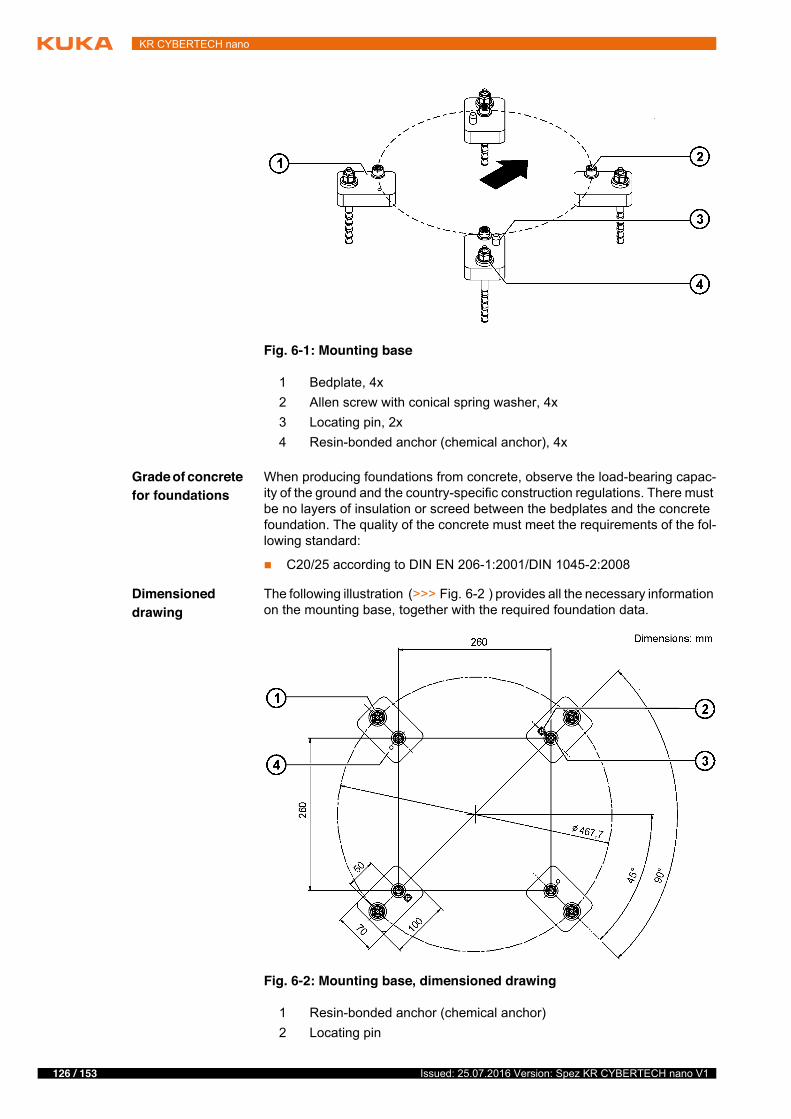
126 / 153 Issued: 25.07.2016 Version: Spez KR CYBERTECH nano V1
KR CYBERTECH nano
Grade of concrete for foundations
When producing foundations from concrete, observe the load-bearing capac-ity of the ground and the country-specific construction regulations. There must be no layers of insulation or screed between the bedplates and the concrete foundation. The quality of the concrete must meet the requirements of the fol-lowing standard:
� C20/25 according to DIN EN 206-1:2001/DIN 1045-2:2008
Dimensioned drawing
The following illustration (>>> Fig. 6-2 ) provides all the necessary information on the mounting base, together with the required foundation data.
Fig. 6-1: Mounting base
1 Bedplate, 4x2 Allen screw with conical spring washer, 4x3 Locating pin, 2x4 Resin-bonded anchor (chemical anchor), 4x
Fig. 6-2: Mounting base, dimensioned drawing
1 Resin-bonded anchor (chemical anchor)2 Locating pin
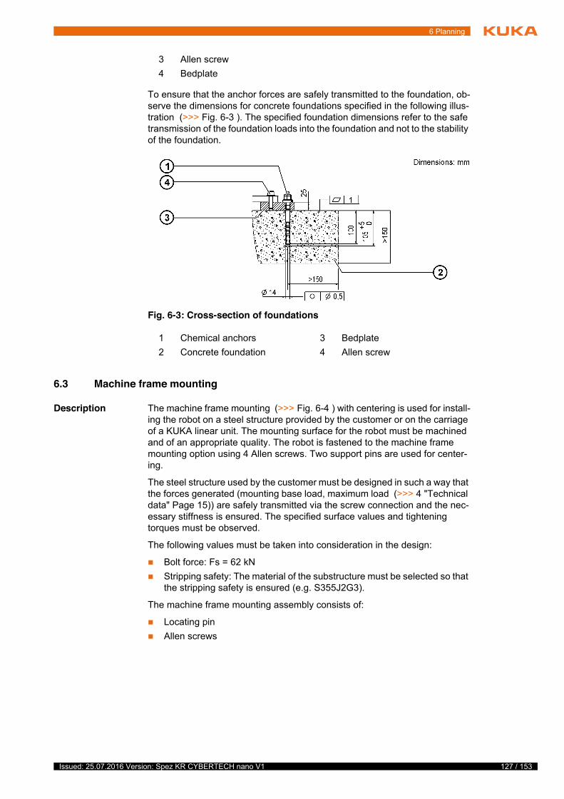
127 / 153Issued: 25.07.2016 Version: Spez KR CYBERTECH nano V1
6 Planning
To ensure that the anchor forces are safely transmitted to the foundation, ob-serve the dimensions for concrete foundations specified in the following illus-tration (>>> Fig. 6-3 ). The specified foundation dimensions refer to the safe transmission of the foundation loads into the foundation and not to the stability of the foundation.
6.3 Machine frame mounting
Description The machine frame mounting (>>> Fig. 6-4 ) with centering is used for install-ing the robot on a steel structure provided by the customer or on the carriage of a KUKA linear unit. The mounting surface for the robot must be machined and of an appropriate quality. The robot is fastened to the machine frame mounting option using 4 Allen screws. Two support pins are used for center-ing.
The steel structure used by the customer must be designed in such a way that the forces generated (mounting base load, maximum load (>>> 4 "Technical data" Page 15)) are safely transmitted via the screw connection and the nec-essary stiffness is ensured. The specified surface values and tightening torques must be observed.
The following values must be taken into consideration in the design:
� Bolt force: Fs = 62 kN� Stripping safety: The material of the substructure must be selected so that
the stripping safety is ensured (e.g. S355J2G3).
The machine frame mounting assembly consists of:
� Locating pin� Allen screws
3 Allen screw4 Bedplate
Fig. 6-3: Cross-section of foundations
1 Chemical anchors 3 Bedplate2 Concrete foundation 4 Allen screw
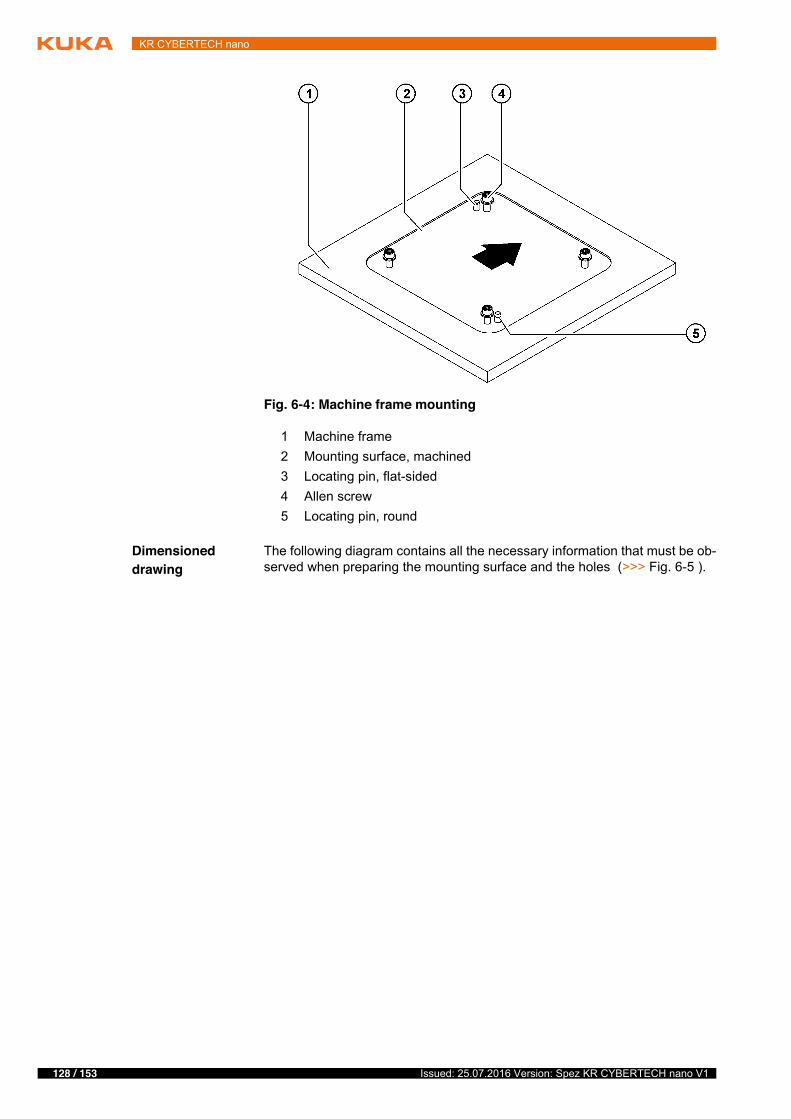
128 / 153 Issued: 25.07.2016 Version: Spez KR CYBERTECH nano V1
KR CYBERTECH nano
Dimensioned drawing
The following diagram contains all the necessary information that must be ob-served when preparing the mounting surface and the holes (>>> Fig. 6-5 ).
Fig. 6-4: Machine frame mounting
1 Machine frame2 Mounting surface, machined3 Locating pin, flat-sided4 Allen screw5 Locating pin, round
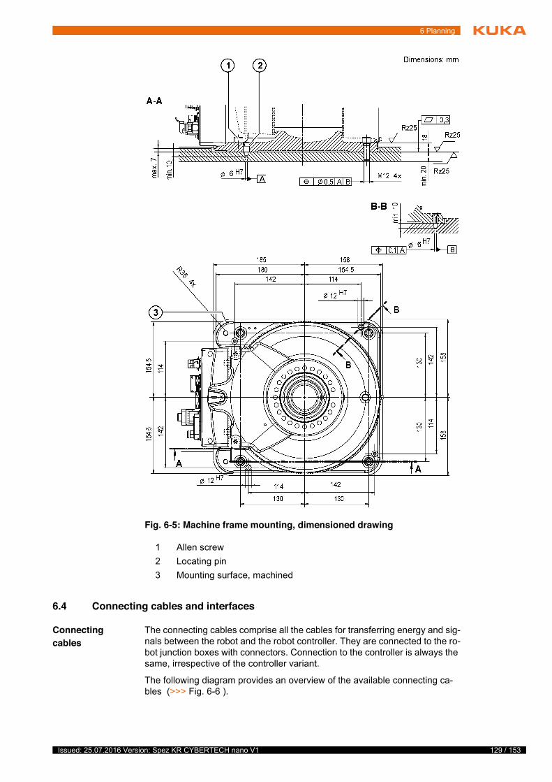
129 / 153Issued: 25.07.2016 Version: Spez KR CYBERTECH nano V1
6 Planning
6.4 Connecting cables and interfaces
Connecting cables
The connecting cables comprise all the cables for transferring energy and sig-nals between the robot and the robot controller. They are connected to the ro-bot junction boxes with connectors. Connection to the controller is always the same, irrespective of the controller variant.
The following diagram provides an overview of the available connecting ca-bles (>>> Fig. 6-6 ).
Fig. 6-5: Machine frame mounting, dimensioned drawing
1 Allen screw 2 Locating pin3 Mounting surface, machined
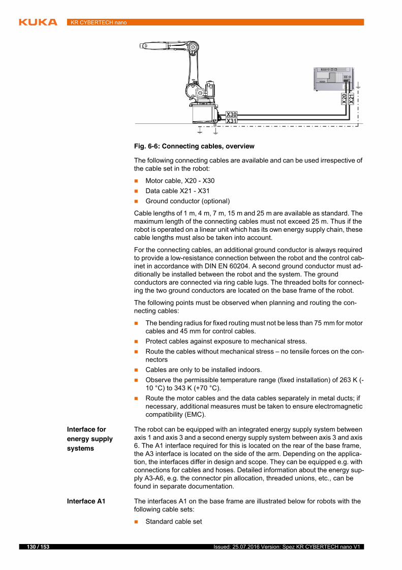
130 / 153 Issued: 25.07.2016 Version: Spez KR CYBERTECH nano V1
KR CYBERTECH nano
The following connecting cables are available and can be used irrespective of the cable set in the robot:
� Motor cable, X20 - X30� Data cable X21 - X31� Ground conductor (optional)
Cable lengths of 1 m, 4 m, 7 m, 15 m and 25 m are available as standard. The maximum length of the connecting cables must not exceed 25 m. Thus if the robot is operated on a linear unit which has its own energy supply chain, these cable lengths must also be taken into account.
For the connecting cables, an additional ground conductor is always required to provide a low-resistance connection between the robot and the control cab-inet in accordance with DIN EN 60204. A second ground conductor must ad-ditionally be installed between the robot and the system. The ground conductors are connected via ring cable lugs. The threaded bolts for connect-ing the two ground conductors are located on the base frame of the robot.
The following points must be observed when planning and routing the con-necting cables:
� The bending radius for fixed routing must not be less than 75 mm for motor cables and 45 mm for control cables.
� Protect cables against exposure to mechanical stress.� Route the cables without mechanical stress – no tensile forces on the con-
nectors� Cables are only to be installed indoors.� Observe the permissible temperature range (fixed installation) of 263 K (-
10 °C) to 343 K (+70 °C).� Route the motor cables and the data cables separately in metal ducts; if
necessary, additional measures must be taken to ensure electromagnetic compatibility (EMC).
Interface for energy supply systems
The robot can be equipped with an integrated energy supply system between axis 1 and axis 3 and a second energy supply system between axis 3 and axis 6. The A1 interface required for this is located on the rear of the base frame, the A3 interface is located on the side of the arm. Depending on the applica-tion, the interfaces differ in design and scope. They can be equipped e.g. with connections for cables and hoses. Detailed information about the energy sup-ply A3-A6, e.g. the connector pin allocation, threaded unions, etc., can be found in separate documentation.
Interface A1 The interfaces A1 on the base frame are illustrated below for robots with the following cable sets:
� Standard cable set
Fig. 6-6: Connecting cables, overview
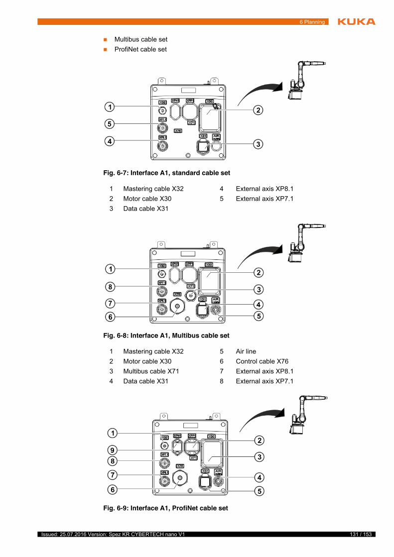
131 / 153Issued: 25.07.2016 Version: Spez KR CYBERTECH nano V1
6 Planning
� Multibus cable set� ProfiNet cable set
Fig. 6-7: Interface A1, standard cable set
1 Mastering cable X32 4 External axis XP8.12 Motor cable X30 5 External axis XP7.13 Data cable X31
Fig. 6-8: Interface A1, Multibus cable set
1 Mastering cable X32 5 Air line2 Motor cable X30 6 Control cable X763 Multibus cable X71 7 External axis XP8.14 Data cable X31 8 External axis XP7.1
Fig. 6-9: Interface A1, ProfiNet cable set
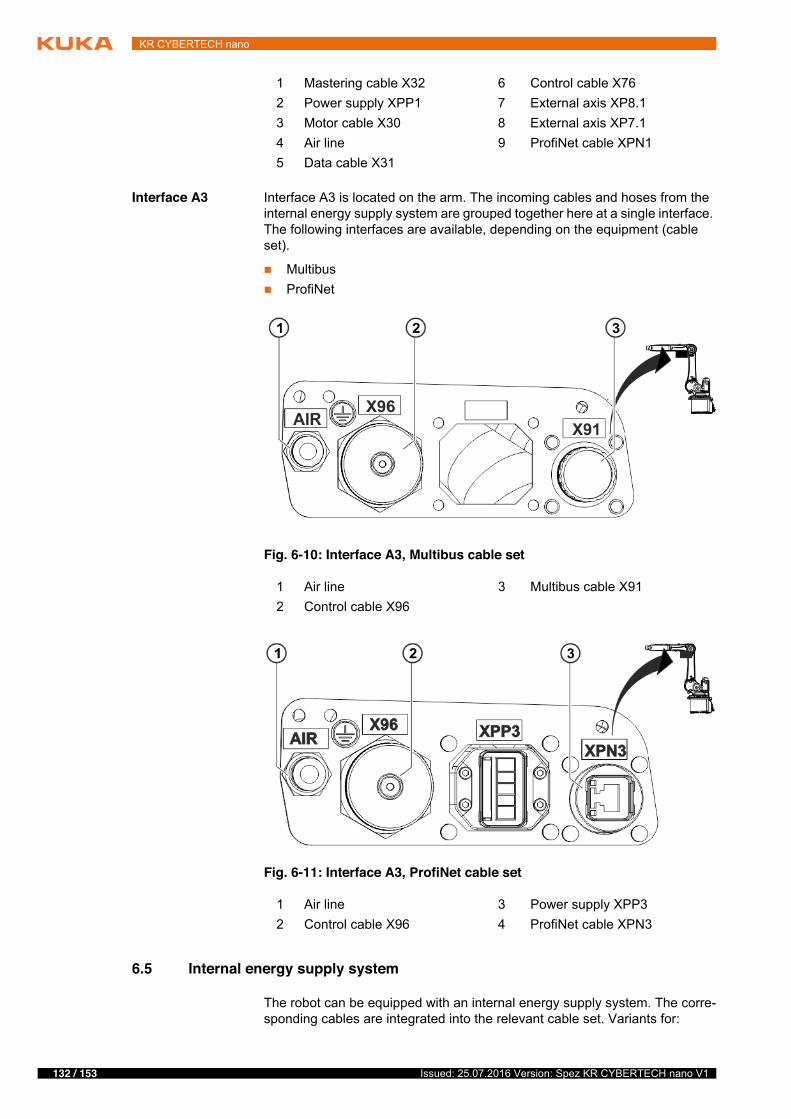
132 / 153 Issued: 25.07.2016 Version: Spez KR CYBERTECH nano V1
KR CYBERTECH nano
Interface A3 Interface A3 is located on the arm. The incoming cables and hoses from the internal energy supply system are grouped together here at a single interface. The following interfaces are available, depending on the equipment (cable set).
� Multibus� ProfiNet
6.5 Internal energy supply system
The robot can be equipped with an internal energy supply system. The corre-sponding cables are integrated into the relevant cable set. Variants for:
1 Mastering cable X32 6 Control cable X762 Power supply XPP1 7 External axis XP8.13 Motor cable X30 8 External axis XP7.14 Air line 9 ProfiNet cable XPN15 Data cable X31
Fig. 6-10: Interface A3, Multibus cable set
1 Air line 3 Multibus cable X912 Control cable X96
Fig. 6-11: Interface A3, ProfiNet cable set
1 Air line 3 Power supply XPP32 Control cable X96 4 ProfiNet cable XPN3
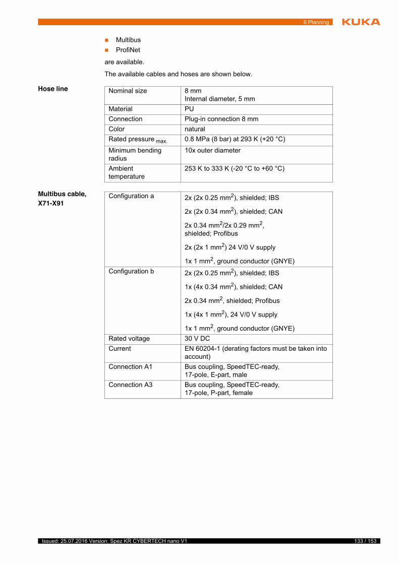
133 / 153Issued: 25.07.2016 Version: Spez KR CYBERTECH nano V1
6 Planning
� Multibus� ProfiNet
are available.
The available cables and hoses are shown below.
Hose line
Multibus cable, X71-X91
Nominal size 8 mm Internal diameter, 5 mm
Material PUConnection Plug-in connection 8 mmColor naturalRated pressure max. 0.8 MPa (8 bar) at 293 K (+20 °C)
Minimum bending radius
10x outer diameter
Ambient temperature
253 K to 333 K (-20 °C to +60 °C)
Configuration a 2x (2x 0.25 mm2), shielded; IBS
2x (2x 0.34 mm2), shielded; CAN
2x 0.34 mm2/2x 0.29 mm2, shielded; Profibus
2x (2x 1 mm2) 24 V/0 V supply
1x 1 mm2, ground conductor (GNYE)Configuration b 2x (2x 0.25 mm2), shielded; IBS
1x (4x 0.34 mm2), shielded; CAN
2x 0.34 mm2, shielded; Profibus
1x (4x 1 mm2), 24 V/0 V supply
1x 1 mm2, ground conductor (GNYE)Rated voltage 30 V DCCurrent EN 60204-1 (derating factors must be taken into
account)Connection A1 Bus coupling, SpeedTEC-ready,
17-pole, E-part, maleConnection A3 Bus coupling, SpeedTEC-ready,
17-pole, P-part, female
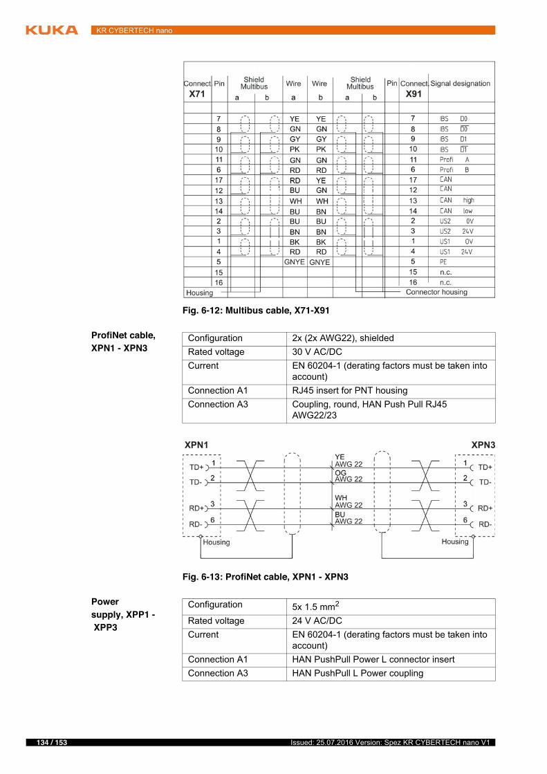
134 / 153 Issued: 25.07.2016 Version: Spez KR CYBERTECH nano V1
KR CYBERTECH nano
ProfiNet cable, XPN1 - XPN3
Power supply, XPP1 - XPP3
Fig. 6-12: Multibus cable, X71-X91
Configuration 2x (2x AWG22), shieldedRated voltage 30 V AC/DCCurrent EN 60204-1 (derating factors must be taken into
account)Connection A1 RJ45 insert for PNT housingConnection A3 Coupling, round, HAN Push Pull RJ45
AWG22/23
Fig. 6-13: ProfiNet cable, XPN1 - XPN3
Configuration 5x 1.5 mm2
Rated voltage 24 V AC/DCCurrent EN 60204-1 (derating factors must be taken into
account)Connection A1 HAN PushPull Power L connector insertConnection A3 HAN PushPull L Power coupling
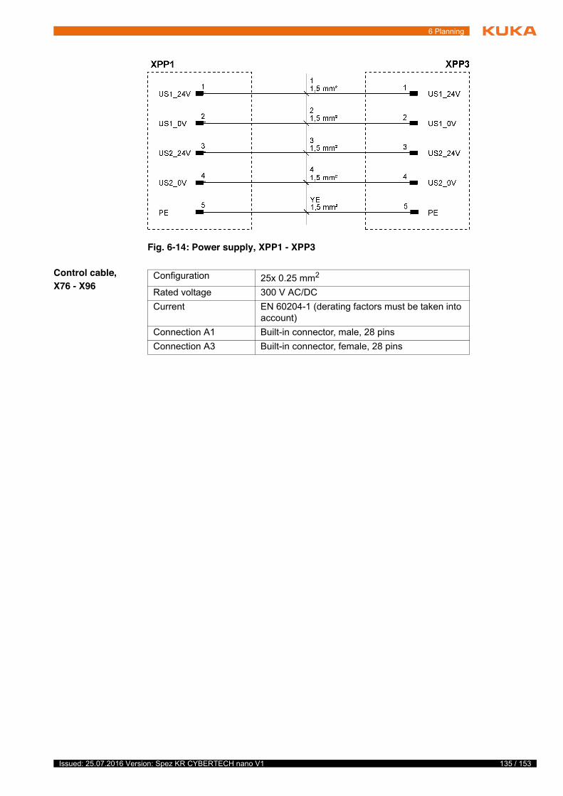
135 / 153Issued: 25.07.2016 Version: Spez KR CYBERTECH nano V1
6 Planning
Control cable, X76 - X96
Fig. 6-14: Power supply, XPP1 - XPP3
Configuration 25x 0.25 mm2
Rated voltage 300 V AC/DCCurrent EN 60204-1 (derating factors must be taken into
account)Connection A1 Built-in connector, male, 28 pinsConnection A3 Built-in connector, female, 28 pins
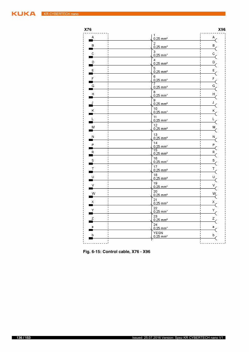
136 / 153 Issued: 25.07.2016 Version: Spez KR CYBERTECH nano V1
KR CYBERTECH nano
Fig. 6-15: Control cable, X76 - X96
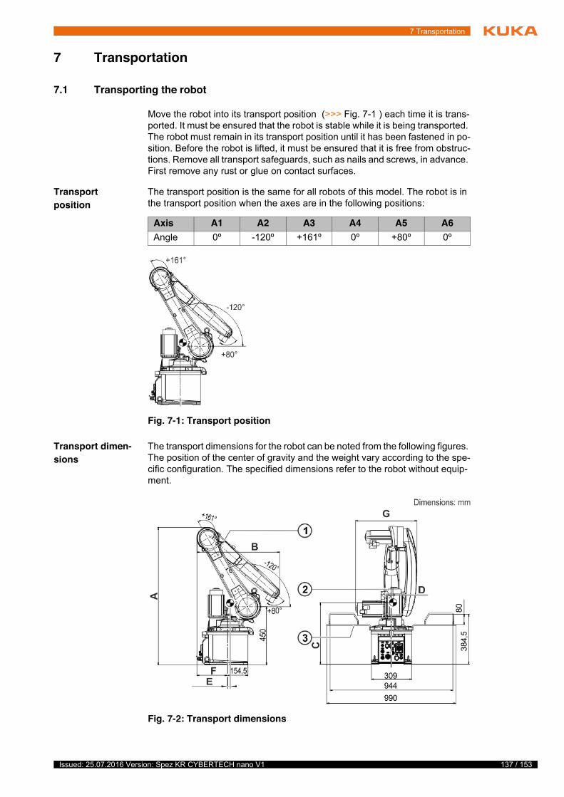
137 / 153Issued: 25.07.2016 Version: Spez KR CYBERTECH nano V1
7 Transportation
7 Transportation
7.1 Transporting the robot
Move the robot into its transport position (>>> Fig. 7-1 ) each time it is trans-ported. It must be ensured that the robot is stable while it is being transported. The robot must remain in its transport position until it has been fastened in po-sition. Before the robot is lifted, it must be ensured that it is free from obstruc-tions. Remove all transport safeguards, such as nails and screws, in advance. First remove any rust or glue on contact surfaces.
Transport position
The transport position is the same for all robots of this model. The robot is in the transport position when the axes are in the following positions:
Transport dimen-sions
The transport dimensions for the robot can be noted from the following figures. The position of the center of gravity and the weight vary according to the spe-cific configuration. The specified dimensions refer to the robot without equip-ment.
T
s
t
t
Axis A1 A2 A3 A4 A5 A6Angle 0º -120º +161º 0º +80º 0º
Fig. 7-1: Transport position
Fig. 7-2: Transport dimensions
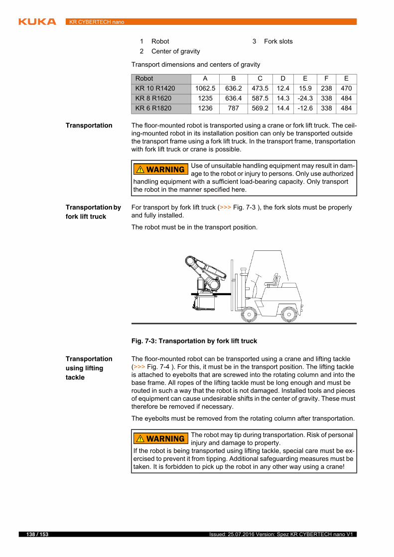
138 / 153 Issued: 25.07.2016 Version: Spez KR CYBERTECH nano V1
KR CYBERTECH nano
Transport dimensions and centers of gravity
Transportation The floor-mounted robot is transported using a crane or fork lift truck. The ceil-ing-mounted robot in its installation position can only be transported outside the transport frame using a fork lift truck. In the transport frame, transportation with fork lift truck or crane is possible.
Transportation by fork lift truck
For transport by fork lift truck (>>> Fig. 7-3 ), the fork slots must be properly and fully installed.
The robot must be in the transport position.
Transportation using lifting tackle
The floor-mounted robot can be transported using a crane and lifting tackle (>>> Fig. 7-4 ). For this, it must be in the transport position. The lifting tackle is attached to eyebolts that are screwed into the rotating column and into the base frame. All ropes of the lifting tackle must be long enough and must be routed in such a way that the robot is not damaged. Installed tools and pieces of equipment can cause undesirable shifts in the center of gravity. These must therefore be removed if necessary.
The eyebolts must be removed from the rotating column after transportation.
1 Robot 3 Fork slots2 Center of gravity
Robot A B C D E F EKR 10 R1420 1062.5 636.2 473.5 12.4 15.9 238 470KR 8 R1620 1235 636.4 587.5 14.3 -24.3 338 484KR 6 R1820 1236 787 569.2 14.4 -12.6 338 484
Use of unsuitable handling equipment may result in dam-age to the robot or injury to persons. Only use authorized
handling equipment with a sufficient load-bearing capacity. Only transport the robot in the manner specified here.
Fig. 7-3: Transportation by fork lift truck
The robot may tip during transportation. Risk of personal injury and damage to property.
If the robot is being transported using lifting tackle, special care must be ex-ercised to prevent it from tipping. Additional safeguarding measures must be taken. It is forbidden to pick up the robot in any other way using a crane!
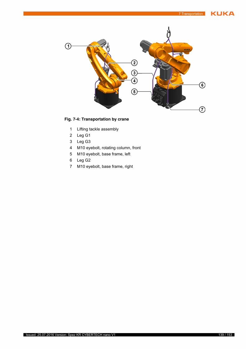
139 / 153Issued: 25.07.2016 Version: Spez KR CYBERTECH nano V1
7 Transportation
Fig. 7-4: Transportation by crane
1 Lifting tackle assembly2 Leg G13 Leg G34 M10 eyebolt, rotating column, front5 M10 eyebolt, base frame, left6 Leg G27 M10 eyebolt, base frame, right

140 / 153 Issued: 25.07.2016 Version: Spez KR CYBERTECH nano V1
KR CYBERTECH nano
141 / 153Issued: 25.07.2016 Version: Spez KR CYBERTECH nano V1
8 Options
8 Options
8.1 Release device (optional)
Description The release device can be used to move the manipulator manually after an ac-cident or malfunction. The release device can be used for the motors of axes A1 to A3. It cannot be used for axes A4 to A6, as these motors are not acces-sible. It is only for use in exceptional circumstances and emergencies (e.g. for freeing people).
The release device is mounted on the base frame of the manipulator. This as-sembly also includes a ratchet and a set of plates with one plate for each mo-tor. The plate specifies the direction of rotation for the ratchet and shows the corresponding direction of motion of the manipulator.
t
s

142 / 153 Issued: 25.07.2016 Version: Spez KR CYBERTECH nano V1
KR CYBERTECH nano
143 / 153Issued: 25.07.2016 Version: Spez KR CYBERTECH nano V1
9 KUKA Service
9 KUKA Service
9.1 Requesting support
Introduction This documentation provides information on operation and operator control, and provides assistance with troubleshooting. For further assistance, please contact your local KUKA subsidiary.
Information The following information is required for processing a support request:
� Description of the problem, including information about the duration and frequency of the fault
� As comprehensive information as possible about the hardware and soft-ware components of the overall systemThe following list gives an indication of the information which is relevant in many cases:� Model and serial number of the kinematic system, e.g. the manipulator� Model and serial number of the controller� Model and serial number of the energy supply system� Designation and version of the system software� Designations and versions of other software components or modifica-
tions� Diagnostic package KRCDiag
Additionally for KUKA Sunrise: Existing projects including applicationsFor versions of KUKA System Software older than V8: Archive of the software (KRCDiag is not yet available here.)
� Application used� External axes used
9.2 KUKA Customer Support
Availability KUKA Customer Support is available in many countries. Please do not hesi-tate to contact us if you have any questions.
Argentina Ruben Costantini S.A. (Agency)Luis Angel Huergo 13 20Parque Industrial2400 San Francisco (CBA)ArgentinaTel. +54 3564 421033Fax +54 3564 [email protected]
Australia KUKA Robotics Australia Pty Ltd45 Fennell StreetPort Melbourne VIC 3207AustraliaTel. +61 3 9939 [email protected]
A
v
144 / 153 Issued: 25.07.2016 Version: Spez KR CYBERTECH nano V1
KR CYBERTECH nano
Belgium KUKA Automatisering + Robots N.V.Centrum Zuid 10313530 HouthalenBelgiumTel. +32 11 516160Fax +32 11 [email protected]
Brazil KUKA Roboter do Brasil Ltda.Travessa Claudio Armando, nº 171Bloco 5 - Galpões 51/52Bairro AssunçãoCEP 09861-7630 São Bernardo do Campo - SPBrazilTel. +55 11 4942-8299Fax +55 11 [email protected]
Chile Robotec S.A. (Agency)Santiago de ChileChileTel. +56 2 331-5951Fax +56 2 [email protected]
China KUKA Robotics China Co., Ltd.No. 889 Kungang RoadXiaokunshan TownSongjiang District201614 ShanghaiP. R. ChinaTel. +86 21 5707 2688Fax +86 21 5707 [email protected]
Germany KUKA Roboter GmbHZugspitzstr. 14086165 AugsburgGermanyTel. +49 821 797-1926Fax +49 821 797-41 [email protected]
145 / 153Issued: 25.07.2016 Version: Spez KR CYBERTECH nano V1
9 KUKA Service
France KUKA Automatisme + Robotique SASTechvallée6, Avenue du Parc91140 Villebon S/YvetteFranceTel. +33 1 6931660-0Fax +33 1 [email protected]
India KUKA Robotics India Pvt. Ltd.Office Number-7, German Centre,Level 12, Building No. - 9BDLF Cyber City Phase III122 002 GurgaonHaryanaIndiaTel. +91 124 4635774Fax +91 124 [email protected]
Italy KUKA Roboter Italia S.p.A.Via Pavia 9/a - int.610098 Rivoli (TO)ItalyTel. +39 011 959-5013Fax +39 011 [email protected]
Japan KUKA Robotics Japan K.K.YBP Technical Center134 Godo-cho, Hodogaya-kuYokohama, Kanagawa240 0005JapanTel. +81 45 744 7691Fax +81 45 744 [email protected]
Canada KUKA Robotics Canada Ltd.6710 Maritz Drive - Unit 4MississaugaL5W 0A1 OntarioCanadaTel. +1 905 670-8600Fax +1 905 [email protected]/canada
146 / 153 Issued: 25.07.2016 Version: Spez KR CYBERTECH nano V1
KR CYBERTECH nano
Korea KUKA Robotics Korea Co. Ltd.RIT Center 306, Gyeonggi Technopark1271-11 Sa 3-dong, Sangnok-guAnsan City, Gyeonggi Do426-901KoreaTel. +82 31 501-1451Fax +82 31 [email protected]
Malaysia KUKA Robot Automation (M) Sdn BhdSouth East Asia Regional OfficeNo. 7, Jalan TPP 6/6Taman Perindustrian Puchong47100 PuchongSelangorMalaysiaTel. +60 (03) 8063-1792Fax +60 (03) [email protected]
Mexico KUKA de México S. de R.L. de C.V.Progreso #8Col. Centro Industrial Puente de VigasTlalnepantla de Baz54020 Estado de MéxicoMexicoTel. +52 55 5203-8407Fax +52 55 [email protected]/mexico
Norway KUKA Sveiseanlegg + RoboterSentrumsvegen 52867 HovNorwayTel. +47 61 18 91 30Fax +47 61 18 62 [email protected]
Austria KUKA Roboter CEE GmbHGruberstraße 2-44020 LinzAustriaTel. +43 7 32 78 47 52Fax +43 7 32 79 38 [email protected]
147 / 153Issued: 25.07.2016 Version: Spez KR CYBERTECH nano V1
9 KUKA Service
Poland KUKA Roboter Austria GmbHSpóáka z ograniczoną odpowiedzialnoĞciąOddziaá w PolsceUl. Porcelanowa 1040-246 KatowicePolandTel. +48 327 30 32 13 or -14Fax +48 327 30 32 [email protected]
Portugal KUKA Robots IBÉRICA, S.A.Rua do Alto da Guerra n° 50Armazém 042910 011 SetúbalPortugalTel. +351 265 729 780Fax +351 265 729 [email protected]
Russia KUKA Robotics RUSWerbnaja ul. 8A107143 MoskauRussiaTel. +7 495 781-31-20Fax +7 495 [email protected]
Sweden KUKA Svetsanläggningar + Robotar ABA. Odhners gata 15421 30 Västra FrölundaSwedenTel. +46 31 7266-200Fax +46 31 [email protected]
Switzerland KUKA Roboter Schweiz AGIndustriestr. 95432 NeuenhofSwitzerlandTel. +41 44 74490-90Fax +41 44 [email protected]
148 / 153 Issued: 25.07.2016 Version: Spez KR CYBERTECH nano V1
KR CYBERTECH nano
Spain KUKA Robots IBÉRICA, S.A.Pol. IndustrialTorrent de la PasteraCarrer del Bages s/n08800 Vilanova i la Geltrú (Barcelona)SpainTel. +34 93 8142-353Fax +34 93 [email protected]
South Africa Jendamark Automation LTD (Agency)76a York RoadNorth End6000 Port ElizabethSouth AfricaTel. +27 41 391 4700Fax +27 41 373 3869www.jendamark.co.za
Taiwan KUKA Robot Automation Taiwan Co., Ltd.No. 249 Pujong RoadJungli City, Taoyuan County 320Taiwan, R. O. C.Tel. +886 3 4331988Fax +886 3 [email protected]
Thailand KUKA Robot Automation (M)SdnBhdThailand Officec/o Maccall System Co. Ltd.49/9-10 Soi Kingkaew 30 Kingkaew RoadTt. Rachatheva, A. BangpliSamutprakarn10540 ThailandTel. +66 2 7502737Fax +66 2 [email protected]
Czech Republic KUKA Roboter Austria GmbHOrganisation Tschechien und SlowakeiSezemická 2757/2193 00 PrahaHorní PoþerniceCzech RepublicTel. +420 22 62 12 27 2Fax +420 22 62 12 27 [email protected]
149 / 153Issued: 25.07.2016 Version: Spez KR CYBERTECH nano V1
9 KUKA Service
Hungary KUKA Robotics Hungaria Kft.Fö út 1402335 TaksonyHungaryTel. +36 24 501609Fax +36 24 [email protected]
USA KUKA Robotics Corporation51870 Shelby ParkwayShelby Township48315-1787 MichiganUSATel. +1 866 873-5852Fax +1 866 [email protected]
UK KUKA Robotics UK LtdGreat Western StreetWednesbury West MidlandsWS10 7LLUKTel. +44 121 505 9970Fax +44 121 505 [email protected]

150 / 153 Issued: 25.07.2016 Version: Spez KR CYBERTECH nano V1
KR CYBERTECH nano
151 / 153Issued: 25.07.2016 Version: Spez KR CYBERTECH nano V1
Index
Index
Numbers2006/42/EC 1222014/30/EU 1222014/68/EC 12295/16/EC 12297/23/EC 122
AAccessories 11, 111Angle of rotation 78ANSI/RIA R.15.06-2012 123Applied norms and regulations 122Automatic mode 120Axis data, KR 10 R1420 17Axis data, KR 10 R1420 HP 46Axis data, KR 6 R1820 36Axis data, KR 6 R1820 HP 66Axis data, KR 8 R1620 26Axis data, KR 8 R1620 HP 56Axis range 113Axis range limitation 115Axis range monitoring 115
BBase frame 12, 14Basic data, KR 10 R1420 16Basic data, KR 10 R1420 HP 45Basic data, KR 6 R1820 35Basic data, KR 6 R1820 HP 65Basic data, KR 8 R1620 25Basic data, KR 8 R1620 HP 55Brake defect 117Brake release device 116Braking distance 113
CCE mark 112Center of gravity 25, 35, 45, 55, 65, 75, 137Cleaning work 121Connecting cables 11, 16, 26, 36, 46, 56, 66, 111, 129Connecting cables, cable lengths 16, 26, 36, 46, 56, 66Counterbalancing system 121
DDanger zone 113Declaration of conformity 112Declaration of incorporation 111, 112Decommissioning 122Description of the robot system 11Dimensions, transport 24, 35, 44, 54, 65, 74, 137Disposal 122Documentation, industrial robot 7
EEC declaration of conformity 112Electrical installations 12, 14
Electromagnetic compatibility (EMC) 123EMC Directive 112, 122EN 60204-1 + A1 123EN 61000-6-2 123EN 61000-6-4 + A1 123EN 614-1 + A1 123EN ISO 10218-1 123EN ISO 12100 123EN ISO 13849-1 123EN ISO 13849-2 123EN ISO 13850 123Extension 78External axes 111, 113
FFaults 118Function test 119
GGeneral information 78General safety measures 117
HHandling equipment 138Hazardous substances 122
IIn-line wrist 12, 13, 21, 31, 41, 51, 61, 71Industrial robot 111Integrated energy supply system 14Intended use 112Interface, energy supply systems 130Interfaces 129Introduction 7
KKCP 11, 79, 113, 117Keyboard, external 117KUKA Customer Support 143KUKA smartPAD 11, 113
LLabeling 116Liability 111Lifting tackle 138Linear unit 111Link arm 12, 13Loads acting on the mounting base 23, 33, 43, 53, 63, 73Loads acting on the mounting base, KR 10 R1420 23Loads acting on the mounting base, KR 10 R1420 HP 53Loads acting on the mounting base, KR 6 R1820 43Loads acting on the mounting base, KR 6 R1820 HP 73Loads acting on the mounting base, KR 8 R1620
152 / 153 Issued: 25.07.2016 Version: Spez KR CYBERTECH nano V1
KR CYBERTECH nano
33Loads acting on the mounting base, KR 8 R1620 HP 63Low Voltage Directive 112
MMachine frame mounting with centering 127Machinery Directive 112, 122main axes 78Maintenance 120Manipulator 11, 111, 113Manual mode 119Mechanical axis range limitation 115Mechanical end stops 115Minimum bending radius 17, 26, 36, 46, 56, 66Mounting base with centering 125Mounting flange 13, 21, 31, 41, 51, 61, 71Mouse, external 117
OOperator 113, 114Options 11, 14, 111, 141Overload 117
PPayload diagram 20, 30, 40, 50, 60, 70Payloads, KR 10 R1420 19Payloads, KR 10 R1420 HP 49Payloads, KR 6 R1820 39Payloads, KR 6 R1820 HP 69Payloads, KR 8 R1620 29Payloads, KR 8 R1620 HP 59Personnel 113Planning 125Plant integrator 113Plates and labels 75Positioner 111Pressure Equipment Directive 121, 122Preventive maintenance work 121Principal components 12Product description 11Program override, motion velocity 78Protective circuit 14Protective equipment, overview 115Purpose 9
RReaction distance 113Recommissioning 118Release device 116Release device, option 141Repair 120Robot controller 11, 111Robot system 11Rotating column 12, 13
SSafety 111Safety instructions 7Safety of machinery 123Safety zone 113, 114
Safety, general 111Service life 113Service, KUKA Roboter GmbH 143smartPAD 79, 113, 117Software 11, 111Start-up 118STOP 0 78, 113STOP 1 78, 113STOP 2 113Stop category 0 113Stop category 1 113Stop category 2 113Stop signal 78Stopping distance 78, 113Stopping distances 78, 79, 85, 90, 95, 100, 105Stopping time 78Stopping times 78, 79, 85, 90, 95, 100, 105Storage 122Supplementary load 22, 32, 42, 52, 62, 72Support request 143System integrator 112, 113, 114
TT1 113T2 113Teach pendant 11, 111Technical data 15Technical data, KR 10 R1420 16Technical data, KR 10 R1420 HP 45Technical data, KR 6 R1820 35Technical data, KR 6 R1820 HP 65Technical data, KR 8 R1620 25Technical data, KR 8 R1620 HP 55Technical data, overview 15Terms used 78Terms used, safety 113Training 9Transport dimensions, KR 10 R1420 24Transport dimensions, KR 10 R1420 HP 54Transport dimensions, KR 6 R1820 44Transport dimensions, KR 6 R1820 HP 74Transport dimensions, KR 8 R1620 35Transport dimensions, KR 8 R1620 HP 65Transport position 137Transportation 118, 137Turn-tilt table 111
UUse, contrary to intended use 111Use, improper 111User 113, 114Users 9
WWarnings 7Working range limitation 115Workspace 113, 114

153 / 153Issued: 25.07.2016 Version: Spez KR CYBERTECH nano V1
KR CYBERTECH nano


![CyberTech Overview v5.3b[1]](https://static.fdocuments.us/doc/165x107/544f41ddb1af9f156f8b5736/cybertech-overview-v53b1.jpg)


