
Kouretes 2008 Nao Team Report - TUC 2008 Nao Team Report Andreas Panakos ... The initial limited...
32
RoboCup 2008 Standard Platform League Kouretes 2008 Nao Team Report Andreas Panakos Alexandros Paraschos Georgios Pierris Daisy Chroni Efstathios Vafeias Eleftherios Chatzilaris Evangelos Vazaios Michail G. Lagoudakis Nikos Vlassis Chania 2008
Transcript of Kouretes 2008 Nao Team Report - TUC 2008 Nao Team Report Andreas Panakos ... The initial limited...
RoboCup 2008
Standard Platform League
Kouretes 2008Nao Team Report
Andreas PanakosAlexandros ParaschosGeorgios PierrisDaisy ChroniEfstathios VafeiasEleftherios ChatzilarisEvangelos VazaiosMichail G. LagoudakisNikos Vlassis
Chania 2008
2 Kouretes 2008
• Contact informationRoboCup Team Kouretesc/o Michail G. LagoudakisDepartment of Electronic and Computer EngineeringTechnical University of CreteChania, 73100 CreteHellas (Greece)Telephone: +30-28210-37244Fax: +30-28210-37542E-mail: kouretes @ intelligence tuc grWeb site: www.kouretes.gr

Table of Contents
1 Introduction . . . . . . . . . . . . . . . . . . . . . . . . . . . . . . . . . . . . . . . . . . . . . . . . . . . 41.1 The RoboCup Competition . . . . . . . . . . . . . . . . . . . . . . . . . . . . . . . . . 41.2 The Standard Platform League . . . . . . . . . . . . . . . . . . . . . . . . . . . . . . 41.3 The Aldebaran Nao Robot . . . . . . . . . . . . . . . . . . . . . . . . . . . . . . . . . 5
2 Team Kouretes . . . . . . . . . . . . . . . . . . . . . . . . . . . . . . . . . . . . . . . . . . . . . . . . 62.1 Team History . . . . . . . . . . . . . . . . . . . . . . . . . . . . . . . . . . . . . . . . . . . . . 62.2 Team Leadership . . . . . . . . . . . . . . . . . . . . . . . . . . . . . . . . . . . . . . . . . . 72.3 Team Members . . . . . . . . . . . . . . . . . . . . . . . . . . . . . . . . . . . . . . . . . . . 72.4 Team Research . . . . . . . . . . . . . . . . . . . . . . . . . . . . . . . . . . . . . . . . . . . . 8
3 Software Architecture . . . . . . . . . . . . . . . . . . . . . . . . . . . . . . . . . . . . . . . . . . 83.1 Kouretes Modules . . . . . . . . . . . . . . . . . . . . . . . . . . . . . . . . . . . . . . . . . 93.2 Robot Communication . . . . . . . . . . . . . . . . . . . . . . . . . . . . . . . . . . . . . 10
4 Complex Motion Patterns . . . . . . . . . . . . . . . . . . . . . . . . . . . . . . . . . . . . . . . 104.1 Kouretes Motion Editor (KME) . . . . . . . . . . . . . . . . . . . . . . . . . . . . . 104.2 KME Concept . . . . . . . . . . . . . . . . . . . . . . . . . . . . . . . . . . . . . . . . . . . . 114.3 Networking . . . . . . . . . . . . . . . . . . . . . . . . . . . . . . . . . . . . . . . . . . . . . . . 124.4 The Graphical User Interface . . . . . . . . . . . . . . . . . . . . . . . . . . . . . . . 134.5 Motion Design . . . . . . . . . . . . . . . . . . . . . . . . . . . . . . . . . . . . . . . . . . . . 134.6 Motion Execution . . . . . . . . . . . . . . . . . . . . . . . . . . . . . . . . . . . . . . . . . 144.7 KME at RoboCup 2008 . . . . . . . . . . . . . . . . . . . . . . . . . . . . . . . . . . . . 144.8 Related Work . . . . . . . . . . . . . . . . . . . . . . . . . . . . . . . . . . . . . . . . . . . . . 154.9 MSRS Motions . . . . . . . . . . . . . . . . . . . . . . . . . . . . . . . . . . . . . . . . . . . . 16
5 Vision . . . . . . . . . . . . . . . . . . . . . . . . . . . . . . . . . . . . . . . . . . . . . . . . . . . . . . . . 165.1 Camera Settings . . . . . . . . . . . . . . . . . . . . . . . . . . . . . . . . . . . . . . . . . . 175.2 Color Segmentation . . . . . . . . . . . . . . . . . . . . . . . . . . . . . . . . . . . . . . . . 185.3 The Nao Color Classifier Tool . . . . . . . . . . . . . . . . . . . . . . . . . . . . . . . 205.4 Image Enhancement . . . . . . . . . . . . . . . . . . . . . . . . . . . . . . . . . . . . . . . 215.5 Object Recognition . . . . . . . . . . . . . . . . . . . . . . . . . . . . . . . . . . . . . . . . 22
6 Behavior . . . . . . . . . . . . . . . . . . . . . . . . . . . . . . . . . . . . . . . . . . . . . . . . . . . . . . 236.1 The Goal Keeper . . . . . . . . . . . . . . . . . . . . . . . . . . . . . . . . . . . . . . . . . . 236.2 The Attacker . . . . . . . . . . . . . . . . . . . . . . . . . . . . . . . . . . . . . . . . . . . . . 24
7 Bipedal Walk . . . . . . . . . . . . . . . . . . . . . . . . . . . . . . . . . . . . . . . . . . . . . . . . . . 247.1 Walk Engine . . . . . . . . . . . . . . . . . . . . . . . . . . . . . . . . . . . . . . . . . . . . . . 247.2 Motion Parametrization . . . . . . . . . . . . . . . . . . . . . . . . . . . . . . . . . . . . 247.3 CPG-Based Walk . . . . . . . . . . . . . . . . . . . . . . . . . . . . . . . . . . . . . . . . . 25
8 Localization . . . . . . . . . . . . . . . . . . . . . . . . . . . . . . . . . . . . . . . . . . . . . . . . . . . 269 Skill Learning . . . . . . . . . . . . . . . . . . . . . . . . . . . . . . . . . . . . . . . . . . . . . . . . . 2810 Conclusion . . . . . . . . . . . . . . . . . . . . . . . . . . . . . . . . . . . . . . . . . . . . . . . . . . . . 31
4 Kouretes 2008
1 Introduction
1.1 The RoboCup Competition
In its short history, the RoboCup competition [1] has grown to a well-establishedannual event bringing together the best robotics researchers from all over theworld. The initial conception by Hiroaki Kitano in 1993 led to the formationof the RoboCup Federation with a bold vision: “By the year 2050, to develop ateam of fully autonomous humanoid robots that can win against the human worldsoccer champions”. The uniqueness of RoboCup stems from the real-world chal-lenge it poses, whereby the core problems of robotics (perception, cognition,action, coordination) must be addressed simultaneously under real-time con-straints. The proposed solutions are tested on a common benchmark environ-ment through soccer games in various leagues, thus setting the stage for demon-strating and promoting the best research approaches, and ultimately advanc-ing the state-of-the-art in the area. Beyond soccer, RoboCup now includes alsocompetitions in search-and-rescue missions (RoboRescue), home keeping tasks(RoboCup@Home), robotic performances (RoboDance), and simplified soccerleagues for K-12 students (RoboCup Junior).
1.2 The Standard Platform League
The Standard Platform League (SPL) of the RoboCup competition (Figure 1)is among the most popular leagues, featuring two to four humanoid AldebaranNao robot players in each team. This league was formerly known as the Four-Legged League featuring Sony Aibo robots which were replaced in 2008. Gamestake place in a 4m× 6m field marked with thick white lines on a green carpet.The two colored goals (skyblue and yellow) also serve as landmarks for enablinglocalization of the robots in the field. Each game consists of two 10-minuteshalves and teams switch colors and side at halftime. There are several rulesenforced by human referees during the game [6]. For example, a player is punishedwith a 30-seconds removal from the field if he performs an illegal action, such aspushing an opponent for more than three seconds, grabbing the ball between hislegs for more than five seconds, leaving the field, or entering his own goal areaas a defender.
The main characteristic of the Standard Platform League is that no hardwarechanges are allowed; all teams use the exact same robotic hardware and differonly in terms of their software. This convention results to the league’s charac-terization by a unique combination of features: autonomous vision-based playeroperation, legged locomotion and action, uniform robotic platform. Given thatthe underlying robotic hardware is common for all competing teams, researchefforts have focused on developing more efficient algorithms and techniques forvisual perception, active localization, omnidirectional motion, skill learning, andcoordination strategies. During the course of the years an independent observercould easily notice a clear progress in all research directions.

Technical University of Crete 5
Fig. 1. Standard Platform League at RoboCup 2008 in Suzhou, China.
1.3 The Aldebaran Nao Robot
Nao is a 57cm, 4.5Kg humanoid robot [2] developed by Aldebaran Roboticsbased in Paris, France. Nao has not been released commercially yet, howeverAldebaran’s goal is to eventually promote Nao as a family entertainment robotaffordable to most budgets. The initial limited edition of the robot made itsdebut at RoboCup 2008, as Nao was selected to be the official robot platform ofthe Standard Platform League.
The Nao robot carries a full computer on board with an x86 AMD Geodeprocessor at 500 Mhz, 256 Mb SDRAM, and 1 Gb flash memory running anEmbedded Linux distribution. It is powered by a Lithium-Ion battery whichprovides about 30 minutes of continuous operation and communicates with re-mote computers via an IEE 802.11g wireless or a wired ethernet link. The Naorobot features a variety of sensors and actuators. A 30fps, 640×480 color cam-era is mounted on the head, while a pair of microphones allows for stereo audioperception. Two ultrasound sensors on the chest allow Nao to sense obstaclesin front of it and a rich inertial unit (2 gyroscopes and 3 accelerometers) in thetorso provides real-time information about its instantaneous body movements.Finally, an array of force sensitive resistors on each foot delivers feedback onthe forces applied to the feet, while encoders on all servos record the actualjoint position at each time and two bumpers on the feet provide information oncollisions of the feet with obstacles. The Nao robot has a total of 21 degrees offreedom; 4 in each arm, 5 in each leg, 2 in the head, and 1 in the pelvis (there

6 Kouretes 2008
are 2 pelvis joints which are coupled together on one servo and cannot move in-dependently). Stereo loudspeakers and a series of LEDs complement its motioncapabilities with auditory and visual actions.
The Nao programming environment is based on the proprietary NaoQi frame-work which serves as a middleware between the robot and high-level languages,such as C++, Ruby, and URBI. NaoQi offers a distributed programming anddebugging environment which can run embedded on the robot or remotely on acomputer and offers an abstraction for event-based parallel and sequential exe-cution. Its architecture is based on modules and brokers which can be executedonboard the robot or remotely and allows the seamless integration of various het-erogeneous components, including proprietary and custom-made functionality.A simple, higher-level, user-friendly programming environment is also providedby the recently released proprietary Choregraphe software. Also, an URBI serveronboard the robot allows direct interaction with the URBI studio developmentenvironment. Finally, there are realistic computer models of the Nao robot avail-able for both the Webots robot simulator [3] and the Microsoft Robotics Studio.
2 Team Kouretes
2.1 Team History
Team Kouretes was founded in February 2006 by Michail G. Lagoudakis andbecame active in the Four-Legged league. In January 2007, under the leadershipof Nikos Vlassis team activities were extended to the Simulation league. Theteam had its first exposure to RoboCup at the RoboCup 2006 event in Bremen,Germany, where it participated in the Technical Challenges of the Four-Leggedleague. At that time, Aibo programming by the team was done exclusively inan interpreted language, the Universal Real-Time Behavior Interface (URBI),without any use of existing code.
Subsequent work led to the participation of the team in the Four-Leggedleague of the RoboCup German Open 2007 competition in Hannover, Germany.The software architecture of the team was developed on the basis of previouslyreleased code by GT2004 and SPQRL 2006. The tournament included ten teamsfrom all over the world. Kouretes reached the quarterfinals round, where it wasdefeated by the 2006 World Champion Nubots. The team ranked in the 7th/8th
place in a tournament featuring the team’s first win and first goals.In Spring 2007, the team began working with the newly-released Microsoft
Robotics Studio (MSRS). The team’s software was developed from scratch ex-clusively in C# and included all the required services, as well as the motionconfiguration files for the simulated RobuDog robot of RoboSoft. The team’sparticipation in the MSRS Simulation Challenge at RoboCup 2007 in Atlantaled to the placement of the team at the 2nd place worldwide bringing the firsttrophy home. The tournament involved nine teams from all over the world;Kouretes was the only European participating team.
In the most recent RoboCup 2008 competition in Suzhou, China the teamparticipated in all divisions of the Standard Platform league (Aibo robots, Nao
Technical University of Crete 7
robots, Nao Webots simulation, Nao MSRS simulation). The team’s efforts wererewarded in the best possible way: 3rd place in Nao league, 1st place in theMSRS simulation, and among the top 8 teams in the Webots simulation.
2.2 Team Leadership
Michail G. Lagoudakis is an assistant professor with the Division of ComputerScience of the Department of Electronic and Computer Engineering (ECE) atthe Technical University of Crete since 2005. He received his Ph.D. degree fromDuke University, USA in 2003 and was a postdoctoral researcher at the Geor-gia Institute of Technology, USA until 2005. His research experience in roboticsspans several areas: path planning, motion control, reinforcement learning, co-ordination.
Nikos Vlassis is an assistant professor with the Division of Production Sys-tems of the Department of Production Engineering and Management (DPEM)at the Technical University of Crete since 2007. He received his Ph.D. degreefrom the Technical University of Athens, Greece in 1998 and was an assistantprofessor with the University of Amsterdam, Netherlands until 2006. His cur-rent research interests include stochastic optimal control, unsupervised learning,and reinforcement learning. Vlassis has extensive experience with the RoboCupSimulation league and various distinctions with the UvA Trilearn robot soccerteam, including the 1st position at the RoboCup world championship (2003),three times 1st position at the German Open tournament (2003, 2004, 2005),and the 1st position at the American Open tournament (2003).
2.3 Team Members
Team Kouretes 2008 includes seven members from two academic departments.The brackets indicate the main area each member has worked on.
1. Andreas Panakos, undergraduate (ECE) [Vision]2. Alexandros Paraschos, undergraduate (ECE) [Software Architecture]3. Georgios Pierris, undergraduate (ECE) [Complex Motion Skills]4. Daisy Chroni, undergraduate (DPEM) [Skill Learning]5. Efstathios Vafeias, undergraduate (DPEM) [MSRS Simulation]6. Eleftherios Chatzilaris, undergraduate (ECE) [Webots Simulation]7. Evangelos Vazaios, undergraduate (ECE) [Robot Communication]
The robotic personnel of the team consists of four Aldebaran Nao (RoboCupedition) robots.
1. Nao 57 [Goal Keeper]2. Nao 53 [Attacker]3. Nao 49 [Bench Robot]4. Nao 13 [Bench Robot]
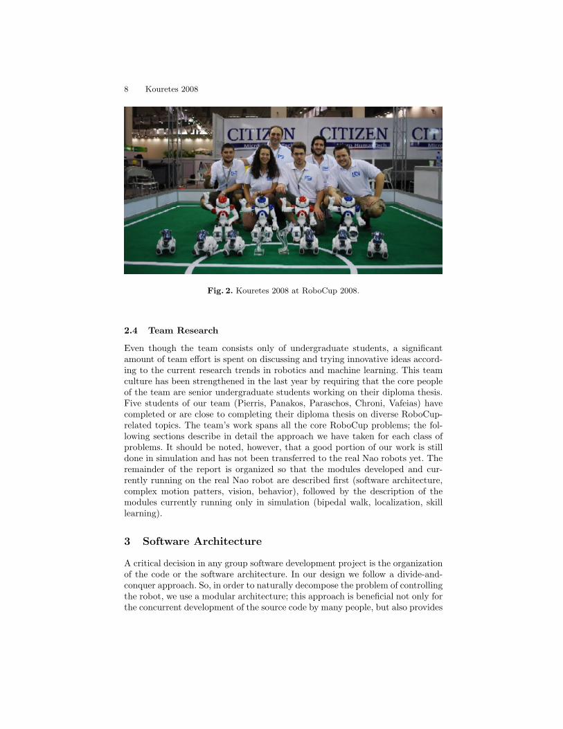
The team is pictured in Figure 2 in Suzhou, China right after the games ofRoboCup 2008 along with the two trophies.
8 Kouretes 2008
Fig. 2. Kouretes 2008 at RoboCup 2008.
2.4 Team Research
Even though the team consists only of undergraduate students, a significantamount of team effort is spent on discussing and trying innovative ideas accord-ing to the current research trends in robotics and machine learning. This teamculture has been strengthened in the last year by requiring that the core peopleof the team are senior undergraduate students working on their diploma thesis.Five students of our team (Pierris, Panakos, Paraschos, Chroni, Vafeias) havecompleted or are close to completing their diploma thesis on diverse RoboCup-related topics. The team’s work spans all the core RoboCup problems; the fol-lowing sections describe in detail the approach we have taken for each class ofproblems. It should be noted, however, that a good portion of our work is stilldone in simulation and has not been transferred to the real Nao robots yet. Theremainder of the report is organized so that the modules developed and cur-rently running on the real Nao robot are described first (software architecture,complex motion patters, vision, behavior), followed by the description of themodules currently running only in simulation (bipedal walk, localization, skilllearning).
3 Software Architecture
A critical decision in any group software development project is the organizationof the code or the software architecture. In our design we follow a divide-and-conquer approach. So, in order to naturally decompose the problem of controllingthe robot, we use a modular architecture; this approach is beneficial not only forthe concurrent development of the source code by many people, but also provides
Technical University of Crete 9
a convenient platform for testing and debugging (due to module independence).Due to restrictions governing the Nao programming interface, we adjust ourarchitecture to be compatible with the Aldebaran’s NaoQi middleware.
3.1 Kouretes Modules
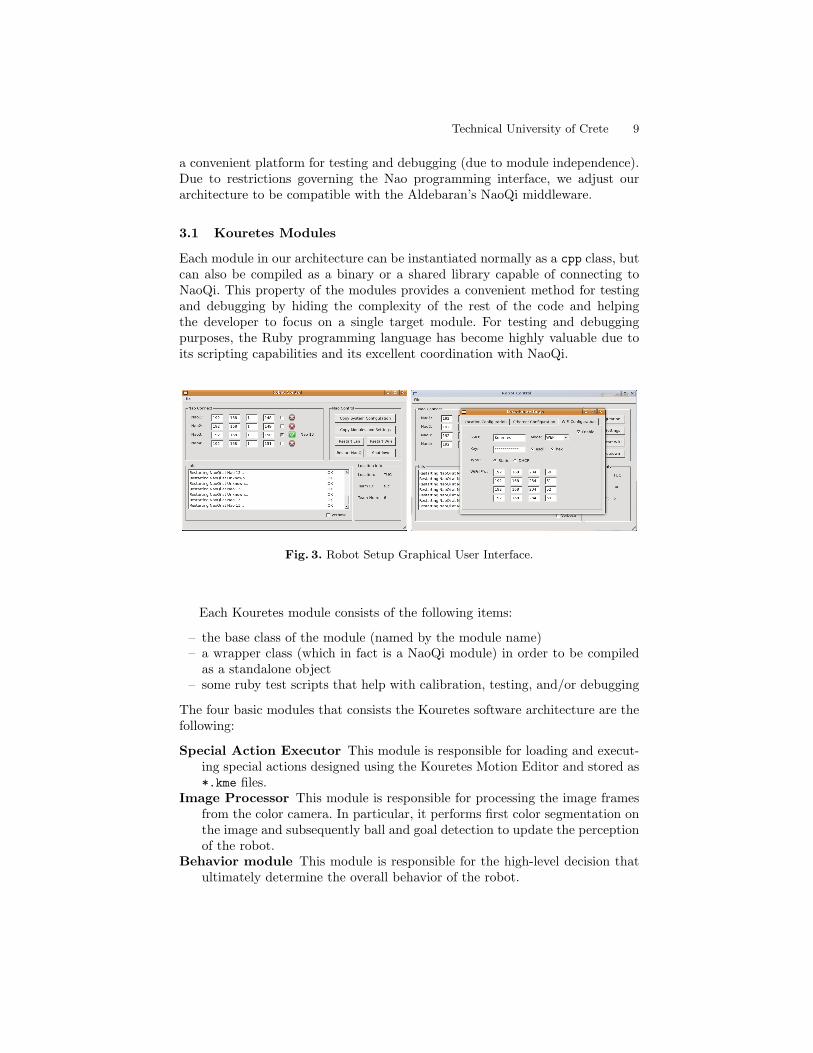
Each module in our architecture can be instantiated normally as a cpp class, butcan also be compiled as a binary or a shared library capable of connecting toNaoQi. This property of the modules provides a convenient method for testingand debugging by hiding the complexity of the rest of the code and helpingthe developer to focus on a single target module. For testing and debuggingpurposes, the Ruby programming language has become highly valuable due toits scripting capabilities and its excellent coordination with NaoQi.
Fig. 3. Robot Setup Graphical User Interface.
Each Kouretes module consists of the following items:
– the base class of the module (named by the module name)– a wrapper class (which in fact is a NaoQi module) in order to be compiled
as a standalone object– some ruby test scripts that help with calibration, testing, and/or debugging
The four basic modules that consists the Kouretes software architecture are thefollowing:
Special Action Executor This module is responsible for loading and execut-ing special actions designed using the Kouretes Motion Editor and stored as*.kme files.
Image Processor This module is responsible for processing the image framesfrom the color camera. In particular, it performs first color segmentation onthe image and subsequently ball and goal detection to update the perceptionof the robot.
Behavior module This module is responsible for the high-level decision thatultimately determine the overall behavior of the robot.

10 Kouretes 2008
Robot Controller This module is responsible for wireless communication withthe game controller and for setting the robot’s state (start, stop, penalized,score, end) during the game.
Finally, the last components of the architecture are the cmake building system,a graphical tool for copying binaries and configuring settings on each robot(Figure 3), and several bash scripts for configuring the architecture.
3.2 Robot Communication
Communication among the robots and communication with the game controllerare vital components of each RoboCup team in order to develop complex behav-ior and cooperation within the team. Our current client is based on the old Aibogame controller, but it could be easily adapted for any new variation of gamecontroller for Nao robots. The client opens a udp socket and listens to the portwhere the data are transmitted. The messages send by the game controller areidentified by the header RGme. After successful identification of data, the clientextracts the transmitted information about the game and the internal state ofthe robot it is running on is updated.
A robot-to-robot communication protocol is still under development to allowfor team coordination and generation of complex strategies and behaviors. Atthis point we are considering a server connection for exchanging generic mes-sages; such a choice will provide a framework for developing various applicationsthat communicate with the robot and could be helpful for real-time observationof the robot behavior and sensors.
4 Complex Motion Patterns
4.1 Kouretes Motion Editor (KME)
This section introduces the Kouretes Motion Editor (KME), an interactive soft-ware tool for designing complex motion patterns on robots with many degreesof freedom using intuitive means. The main idea behind KME is the ability togenerate, store, manipulate, edit, and replay sequences of (complete or partial)robot poses, which resemble the desired complex motion pattern. KME allowsfor interactive design through a TCP/IP network connection to a real or sim-ulated robot, over which various robot poses can be communicated to or fromthe robot and manipulated locally using the KME graphical user interface. Thisportability and flexibility enables the user to work under different modes (con-figuration or Cartesian space), with different robots (real or simulated), usingdifferent host machines (for running KME itself).
KME was originally designed for and currently supports only the AldebaranNao humanoid robot (RoboCup edition) [2] and its simulated model on the We-bots simulator [3]. However, the main features of KME could be easily adaptedfor other robots and the tool itself could be used for a variety of purposes, suchas providing complex motion patterns as starting points for learning algorithms

Technical University of Crete 11
and supporting educational activities in robot programming courses. KME hasbeen employed successfully for designing various special actions (stand-up, ballkicks, goalie falls) during RoboCup 2008.
4.2 KME Concept
The goal behind the development of KME is to provide an abstract motiondesign environment for the common robot practitioner, which hides away thetechnical details of low-level joint control and strikes a balance between for-mal motion definition using precise joint angles in the configuration space ofthe robot and intuitive motion definition using manual joint positioning in thereal-world work space of the robot. Such an abstraction yields a number of ben-efits, which served also as the driving force behind this work: (a) arbitrarilycomplex motion patterns can be easily designed without ever writing a singleline of code, (b) motion patterns can be rapidly designed and tested through asimple and friendly interface, (c) motion patterns designed by one user can beeasily shared, understood, used, and modified by other users, (d) various realand/or simulated robots can be accommodated simply by adapting the back-end of the tool, (e) resulting motion patterns can be used as seeds in learningalgorithms for further fine-tuning, and (f) proprietary motion patterns could bereverse-engineered as recorded sequences of complete or partial robot poses andsubsequently manipulated at will.
Towards this end, KME is implemented as a client-server architecture, wherebythe client and the server sides are interconnected over a TCP/IP network as de-scribed below. The server is a special “controller” running on the real robot or onthe simulator; it simply listens for a client on specific ports and undertakes therole of transferring joint values between the robot and the client, once a clientis connected. The client is an independent application running on the local orany remote machine and provides the graphical user interface (GUI) describedbelow. Communication between the client and the server is bi-directional; anyset of joint values provided by the client can be transferred to the server anddrive the robot joints to the designated pose, and conversely the current jointvalues on the robot can be read and transferred from the server to the client forstorage and further manipulation.
For maximum portability, it was decided to use open source software for thedevelopment of KME. In particular, the core code is written in C++ and can becompiled under any popular operating system (Linux, Windows, MacOS) usinga standard C++ compiler. The current graphical environment is based on FLTKlibraries [4], however the core code is structured in a way that allows interfacingwith other popular graphical toolkits, such as Qt and Tcl/Tk. Finally, the realrobot server has been written in the interpreted script language Ruby to avoidcostly cross-compilation times.
12 Kouretes 2008
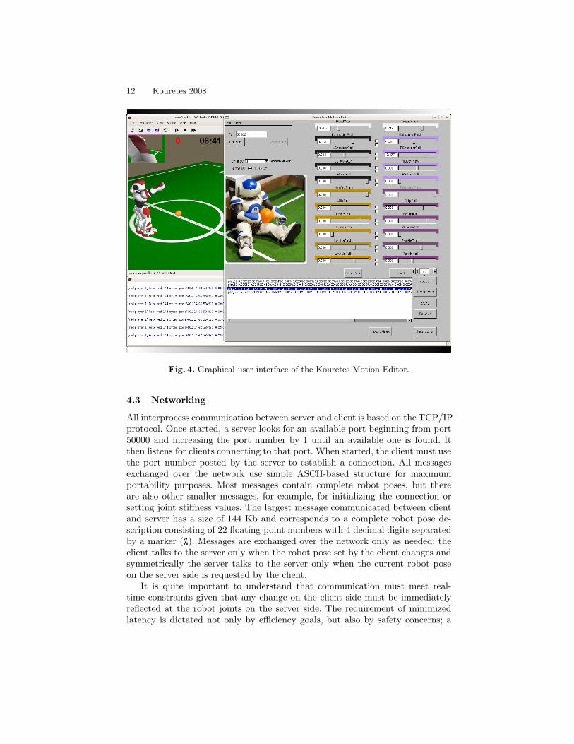
Fig. 4. Graphical user interface of the Kouretes Motion Editor.
4.3 Networking
All interprocess communication between server and client is based on the TCP/IPprotocol. Once started, a server looks for an available port beginning from port50000 and increasing the port number by 1 until an available one is found. Itthen listens for clients connecting to that port. When started, the client must usethe port number posted by the server to establish a connection. All messagesexchanged over the network use simple ASCII-based structure for maximumportability purposes. Most messages contain complete robot poses, but thereare also other smaller messages, for example, for initializing the connection orsetting joint stiffness values. The largest message communicated between clientand server has a size of 144 Kb and corresponds to a complete robot pose de-scription consisting of 22 floating-point numbers with 4 decimal digits separatedby a marker (%). Messages are exchanged over the network only as needed; theclient talks to the server only when the robot pose set by the client changes andsymmetrically the server talks to the server only when the current robot poseon the server side is requested by the client.
It is quite important to understand that communication must meet real-time constraints given that any change on the client side must be immediatelyreflected at the robot joints on the server side. The requirement of minimizedlatency is dictated not only by efficiency goals, but also by safety concerns; a
Technical University of Crete 13
motion executed on the robot several seconds or minutes later than expecteddue to a network freeze or congestion may have fatal consequences. Under thecurrent communication protocol, the server and the client run smoothly andtransparently in a robust and predictable way even over the wireless link betweenthe robot and the computer.
4.4 The Graphical User Interface
The KME graphical user interface provides the means for the creation, man-agement, storage, and reproduction of any sequence of robot poses. The entireGUI consists of three components as shown in Figure 4. The component on theleft-hand side is responsible for establishing a connection to a server using aspecific port number and for turning joint stiffness and balance mode on andoff as needed. The component on the right-hand side offers 22 sliders, one foreach joint of the robot; two of them (L/R HipYawPitch) are clamped together.The user can set the value of any joint either by sliding the corresponding sliderto the desired position or by setting directly the desired arithmetic value. Anychange made to a joint value is immediately communicated to the robot throughthe server (if stiffness on the robot joints is enabled), therefore the current robotpose coded by the slider values is always reflected on the robot. Finally, thecomponent at the bottom is a robot pose editor. The list of poses can be editedas needed; poses can be inserted to or deleted from the list, and they can beswapped with other poses or moved up and down to the desired position in thelist.
4.5 Motion Design
Any complex motion pattern created using KME is a timed sequence of robotposes in the configuration space. Robot poses can be created either by settingjoint values through the sliders of the GUI or by capturing the current jointvalues of the real or simulated robot. The current robot pose coded in the sliderscan be captured and stored at any time in the editable list of poses using the“Save Pose” button. Alternatively, the user may manually move the robot jointsto any desired configuration (under no stiffness) and use the “Load Values”button to capture the current joint values. The user can also adjust the transitiontime between subsequent poses, which implicitly determines the speed in themotion of each joint. Finally, the user can “play” the current pose sequencefrom any point (either in a step-by-step fashion or continuously) to observe thecomplete motion pattern on the robot. Once the desired movement is complete,the pose sequence can be exported to a file and can be further used within anyrobot controller by simply invoking a motion execution routine.
Designing motion patterns using KME can become a lot more interactive,as we discovered along the way. Consider two consequent robot poses A andB. The user may want the robot to move from pose A to pose B in a certainamount of time, however this may not be possible because of limited accelerationor mechanical load constraints. Using the step-by-step execution, the user may
14 Kouretes 2008
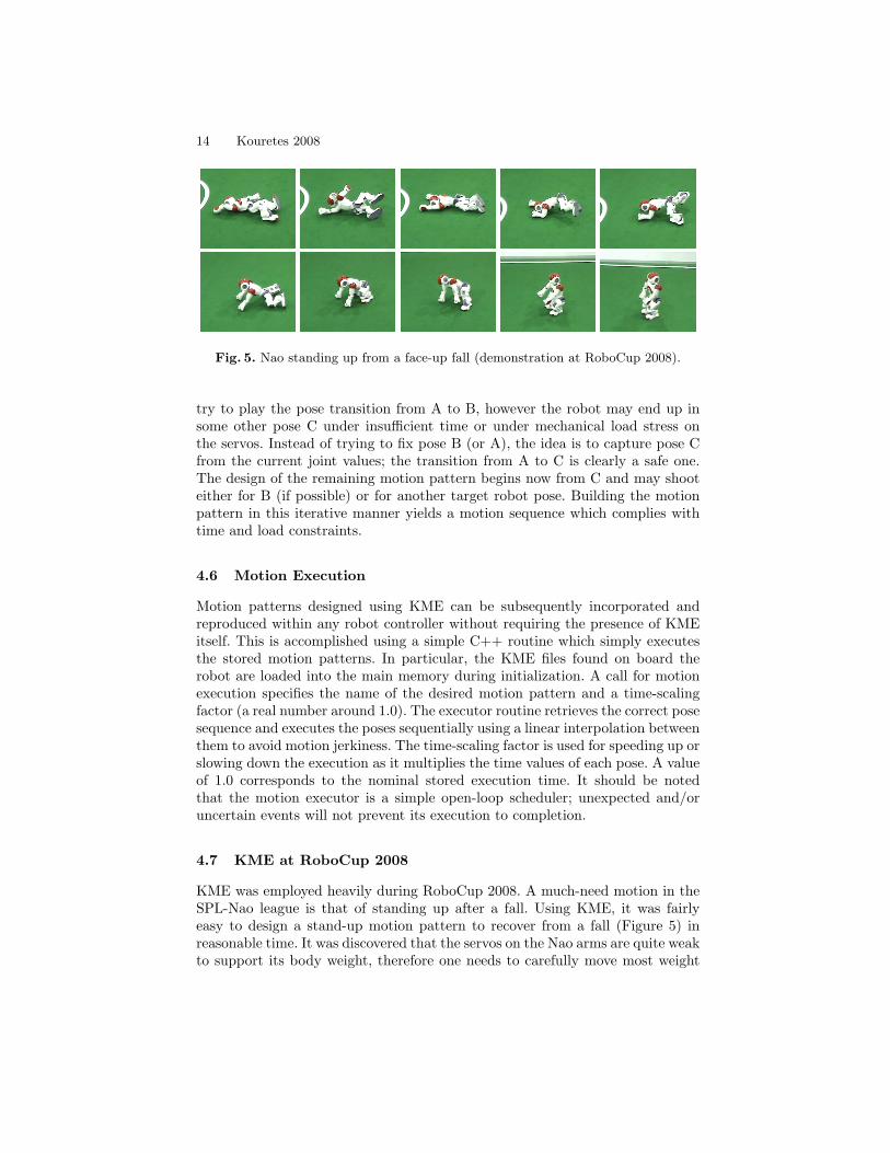
Fig. 5. Nao standing up from a face-up fall (demonstration at RoboCup 2008).
try to play the pose transition from A to B, however the robot may end up insome other pose C under insufficient time or under mechanical load stress onthe servos. Instead of trying to fix pose B (or A), the idea is to capture pose Cfrom the current joint values; the transition from A to C is clearly a safe one.The design of the remaining motion pattern begins now from C and may shooteither for B (if possible) or for another target robot pose. Building the motionpattern in this iterative manner yields a motion sequence which complies withtime and load constraints.
4.6 Motion Execution
Motion patterns designed using KME can be subsequently incorporated andreproduced within any robot controller without requiring the presence of KMEitself. This is accomplished using a simple C++ routine which simply executesthe stored motion patterns. In particular, the KME files found on board therobot are loaded into the main memory during initialization. A call for motionexecution specifies the name of the desired motion pattern and a time-scalingfactor (a real number around 1.0). The executor routine retrieves the correct posesequence and executes the poses sequentially using a linear interpolation betweenthem to avoid motion jerkiness. The time-scaling factor is used for speeding up orslowing down the execution as it multiplies the time values of each pose. A valueof 1.0 corresponds to the nominal stored execution time. It should be notedthat the motion executor is a simple open-loop scheduler; unexpected and/oruncertain events will not prevent its execution to completion.
4.7 KME at RoboCup 2008
KME was employed heavily during RoboCup 2008. A much-need motion in theSPL-Nao league is that of standing up after a fall. Using KME, it was fairlyeasy to design a stand-up motion pattern to recover from a fall (Figure 5) inreasonable time. It was discovered that the servos on the Nao arms are quite weakto support its body weight, therefore one needs to carefully move most weight

Technical University of Crete 15
to the legs for a successful stand-up. It was also discovered that to recover froma face-up fall (or even a side fall), it was best to move first into a face-downpose and then execute the stand-up motion. The complete stand-up procedureuses the inertial sensors of the robot to determine the orientation of the robotbody after a fall and executes appropriate motions that first bring the robot toa face-down pose before attempting a stand-up motion. Surprisingly, this stand-up motion designed on the carpet at the home laboratory did not work on thecarpet at the competition venue. Thanks to KME, it took only about 30 minutesand two people holding the robot to design from scratch a new stand-up motionfor the new carpet. KME was also used for designing other necessary movementsfor the Nao league (ball kicks and goalkeeper actions).
Video clips taken during actual games demonstrating some of the motionpatterns (ball kick, goalkeeper actions, stand-up) designed using KME may befound on the team’s web site. Kouretes was the only one of the 15 participatingteams who demonstrated a live stand-up motion and one of the few teams whoused goalkeeper actions during the games. The team ended up winning the 3rdplace in the league and a good deal of this success was due to KME.
4.8 Related Work
KME offers some innovative ideas, however there exist similar tools for designingcomplex motion patterns. The most closely-related tool is Choregraphe as it wasdeveloped specifically for the Aldebaran Nao robot. Two other related tools forthe Sony Aibo robots are Skitter and Aibo Motion Editor.
Choregraphe is a proprietary software package developed by Aldebaran Roboticsto facilitate complex behavior programming on the Nao robot. Its first releasecame out in June 2008, well after the development of KME, but unfortunatelyit is still flooded with various bugs that make development a tedious process.Choregraphe offers a cross-platform environment that allows the user to buildvarious movements and behaviors on the Nao robot. To this end, it combinestime-based and event-based approaches. Time-based design is used to schedulemotions and multimedia material over time. Different timelines can be used de-pending on the current execution context. An event manager is responsible foridentifying the current context based on the occurrence of events and trigger-ing the appropriate behaviors. Choregraphe’s capabilities are well beyond KMEcapabilities. Nevertheless, KME offers at least two advantages: (a) focus on mo-tion design only, and (b) robust real-time performance. Our experience withChoregraphe so far has been disappointing for the the purpose of motion design;there are serious bugs in the code and its heavy system requirements occasion-ally results in unexpected event triggering. Our anecdotal story includes a walkcommand which was executed on the robot about 10 minutes after its issuancethrough Choregraphe!
The Sony Aibo robot is another popular robot featuring a total of 20 degreesof freedom. Despite its commercial discontinuation in 2006, Aibo robots are stillused in various research and educational efforts. The original Aibo Motion Editorprovided by Sony is a graphical tool that allows users to generate complex motion

16 Kouretes 2008
patterns as sequences of poses, similarly to KME. Unfortunately, its first releasewas incomplete and was never completed in subsequent years. While the designof motion patterns is fairly through direct setting of joint values or throughmanual joint positioning on a VRML robot model, export and integration ofsuch motion patterns into generic robot controllers and applications is rathercumbersome (each pose is saved as a separate file and motion can be uploadedonly through R-Tool, a custom-made tool, and triggered only through R-Code,a custom language for Aibos. Skitter1 is another motion editor for Aibo robotswith more capabilities. It allows combinations of motions (20 degrees of freedom),lights (32 independent LEDs), and sounds (MIDI and WAN playback) along atime line. Such combinations are called skits and can last up to 4 minutes. Skitsare designed using plots over time and a VRML robot model which can be usedfor visualization, but can also be manually positioned for capturing poses. Theresulting motion patterns can be exported for use on the real robot, again onlythrough R-Code.
The distinguishing feature of KME missing from the tools mentioned aboveis the ability to directly interact in real-time with the real robot and designsafe and robust motion patterns in an iterative manner as discussed in earliersections, as well as the flexibility in incorporating the resulting motions in avariety of robot software architectures. It is important to stress out the factthat working directly with the real robot overcomes several difficulties occurringwhen motion patterns designed on a VRML model without sense of physicsand/or mechanical, dynamic, and kinematic constraints do not yield the desiredeffect on the real robot. Unlike the tools above, KME currently focuses only onmotion, ignoring light and sound, which really fall outside its scope and purpose.In summary, KME can complement the tools above and provide an alternativedesign tool when motion alone is at focus.
4.9 MSRS Motions
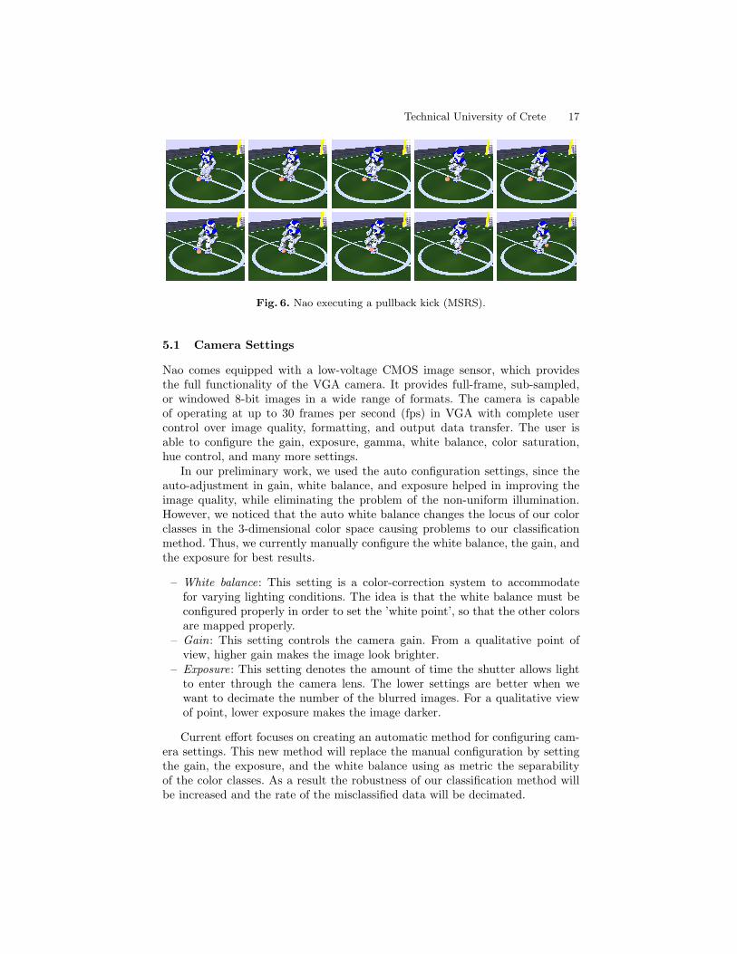
A different collection of complex motion patterns has been developed indepen-dently through our work on the Microsoft Robotics Studio. While these havebeen used heavily in the MSRS simulation games, we believe that with little orno effort they can be ported to the real Nao robot. Figure 6 shows the mostimpressive of these actions, namely a pull back kick.
5 Vision
Since the ability of an autonomous robot to sense its environment is crucial foreffective action selection, we have emphasized on the vision module of our team.The vision module processes the images taken by the CMOS VGA camera onthe Nao’s forehead and consists of two consecutive steps: color segmentation andobject recognition.
1 www.dogsbodynet.com/skitter.html
Technical University of Crete 17
Fig. 6. Nao executing a pullback kick (MSRS).
5.1 Camera Settings
Nao comes equipped with a low-voltage CMOS image sensor, which providesthe full functionality of the VGA camera. It provides full-frame, sub-sampled,or windowed 8-bit images in a wide range of formats. The camera is capableof operating at up to 30 frames per second (fps) in VGA with complete usercontrol over image quality, formatting, and output data transfer. The user isable to configure the gain, exposure, gamma, white balance, color saturation,hue control, and many more settings.
In our preliminary work, we used the auto configuration settings, since theauto-adjustment in gain, white balance, and exposure helped in improving theimage quality, while eliminating the problem of the non-uniform illumination.However, we noticed that the auto white balance changes the locus of our colorclasses in the 3-dimensional color space causing problems to our classificationmethod. Thus, we currently manually configure the white balance, the gain, andthe exposure for best results.
– White balance: This setting is a color-correction system to accommodatefor varying lighting conditions. The idea is that the white balance must beconfigured properly in order to set the ’white point’, so that the other colorsare mapped properly.
– Gain: This setting controls the camera gain. From a qualitative point ofview, higher gain makes the image look brighter.
– Exposure: This setting denotes the amount of time the shutter allows lightto enter through the camera lens. The lower settings are better when wewant to decimate the number of the blurred images. For a qualitative viewof point, lower exposure makes the image darker.
Current effort focuses on creating an automatic method for configuring cam-era settings. This new method will replace the manual configuration by settingthe gain, the exposure, and the white balance using as metric the separabilityof the color classes. As a result the robustness of our classification method willbe increased and the rate of the misclassified data will be decimated.
18 Kouretes 2008
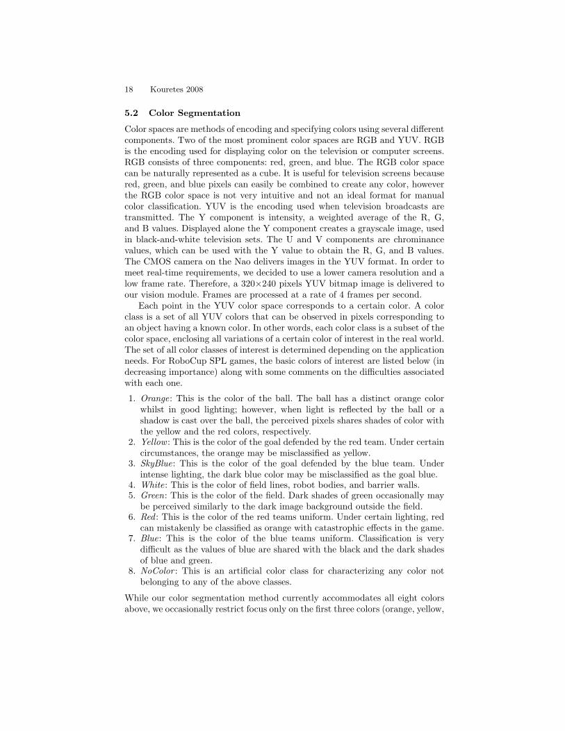
5.2 Color Segmentation
Color spaces are methods of encoding and specifying colors using several differentcomponents. Two of the most prominent color spaces are RGB and YUV. RGBis the encoding used for displaying color on the television or computer screens.RGB consists of three components: red, green, and blue. The RGB color spacecan be naturally represented as a cube. It is useful for television screens becausered, green, and blue pixels can easily be combined to create any color, howeverthe RGB color space is not very intuitive and not an ideal format for manualcolor classification. YUV is the encoding used when television broadcasts aretransmitted. The Y component is intensity, a weighted average of the R, G,and B values. Displayed alone the Y component creates a grayscale image, usedin black-and-white television sets. The U and V components are chrominancevalues, which can be used with the Y value to obtain the R, G, and B values.The CMOS camera on the Nao delivers images in the YUV format. In order tomeet real-time requirements, we decided to use a lower camera resolution and alow frame rate. Therefore, a 320×240 pixels YUV bitmap image is delivered toour vision module. Frames are processed at a rate of 4 frames per second.
Each point in the YUV color space corresponds to a certain color. A colorclass is a set of all YUV colors that can be observed in pixels corresponding toan object having a known color. In other words, each color class is a subset of thecolor space, enclosing all variations of a certain color of interest in the real world.The set of all color classes of interest is determined depending on the applicationneeds. For RoboCup SPL games, the basic colors of interest are listed below (indecreasing importance) along with some comments on the difficulties associatedwith each one.
1. Orange: This is the color of the ball. The ball has a distinct orange colorwhilst in good lighting; however, when light is reflected by the ball or ashadow is cast over the ball, the perceived pixels shares shades of color withthe yellow and the red colors, respectively.
2. Yellow : This is the color of the goal defended by the red team. Under certaincircumstances, the orange may be misclassified as yellow.
3. SkyBlue: This is the color of the goal defended by the blue team. Underintense lighting, the dark blue color may be misclassified as the goal blue.
4. White: This is the color of field lines, robot bodies, and barrier walls.5. Green: This is the color of the field. Dark shades of green occasionally may
be perceived similarly to the dark image background outside the field.6. Red : This is the color of the red teams uniform. Under certain lighting, red
can mistakenly be classified as orange with catastrophic effects in the game.7. Blue: This is the color of the blue teams uniform. Classification is very
difficult as the values of blue are shared with the black and the dark shadesof blue and green.
8. NoColor : This is an artificial color class for characterizing any color notbelonging to any of the above classes.
While our color segmentation method currently accommodates all eight colorsabove, we occasionally restrict focus only on the first three colors (orange, yellow,

Technical University of Crete 19
skyblue), which correspond to the key objects in the field; all other colors aregrouped under the NoColor class. Segmenting the image into more colors isstraightforward and only requires increased human effort to label additionaltraining data.
For color classification we use modern classification technology. We havetested mainly decision trees (DT) and support vector machines (SVM), butdecision trees were found to be faster and more robust for the successful classi-fication of colors. For training a decision tree we use the C4.5 algorithm, oftenreferred to as statistical classifier, developed by Ross Quinlan [8]. C4.5 builds de-cision trees from a set of training data using the concept of information entropy.The training data consist of a set S = {s1, s2, . . . , sn} of n labeled samples. Thelabels are indicated by a vector C = (c1, c2, . . . , cn), whereby ci represents theclass sample si belongs to. Each sample si = (x1, x2, . . . , xk} is described bya k-dimensional vector, where the xj ’s represent the attributes or features ofthe sample si. C4.5 uses the fact that each attribute of the data can be usedto make a decision that splits the data into smaller subsets. C4.5 examines thenormalized information gain, that is, the difference in entropy that results fromchoosing an attribute for splitting the data. The attribute with the highest nor-malized information gain is the one used to make the decision at that point. Thealgorithm then continues recursively on the smaller subsets. This algorithm hasa few base cases, the most common base case is when all the samples in yourlist belong to the same class. Once this happens, you simply create a leaf nodefor your decision tree telling you to choose that class. It might also happen thatnone of the features give you any information gain, in this case C4.5 creates adecision node higher up the tree using the expected value of the class. It alsomight happen that you’ve never seen any instances of a class; again, C4.5 createsa decision node higher up the tree using the expected value.
Independently of the classifier choice, YUV values received by the camera arethe inputs to the classifier and a color class label is the output. Regarding thenumber of input attributes, the simplest choice is to use the YUV values of thecurrent pixel (N1 scheme). However, under difficult lighting situations, we canexploit color locality by using as input attributes not only the YUV values of thecurrent pixel, but also the UYV values of pixels in its immediate neighborhood.These can be the 4 orthonormal, the 4 diagonal, or the 8 orthonormal/diagonalneighboring pixels. Through extensive experimentation we found that the neigh-borhood of the 4 diagonal neighboring pixels works best for our purposes; underthis scheme, the YUV values of 5 pixels in total are taken as the input attributes(N5 scheme).
Our classification method has been implemented in such a way that the colorspace, the number of input attributes of the training data, the classifier model,and the training algorithm can be easily modified. With this parametric designwe are able to test various configurations and choose the most appropriate.
20 Kouretes 2008
5.3 The Nao Color Classifier Tool
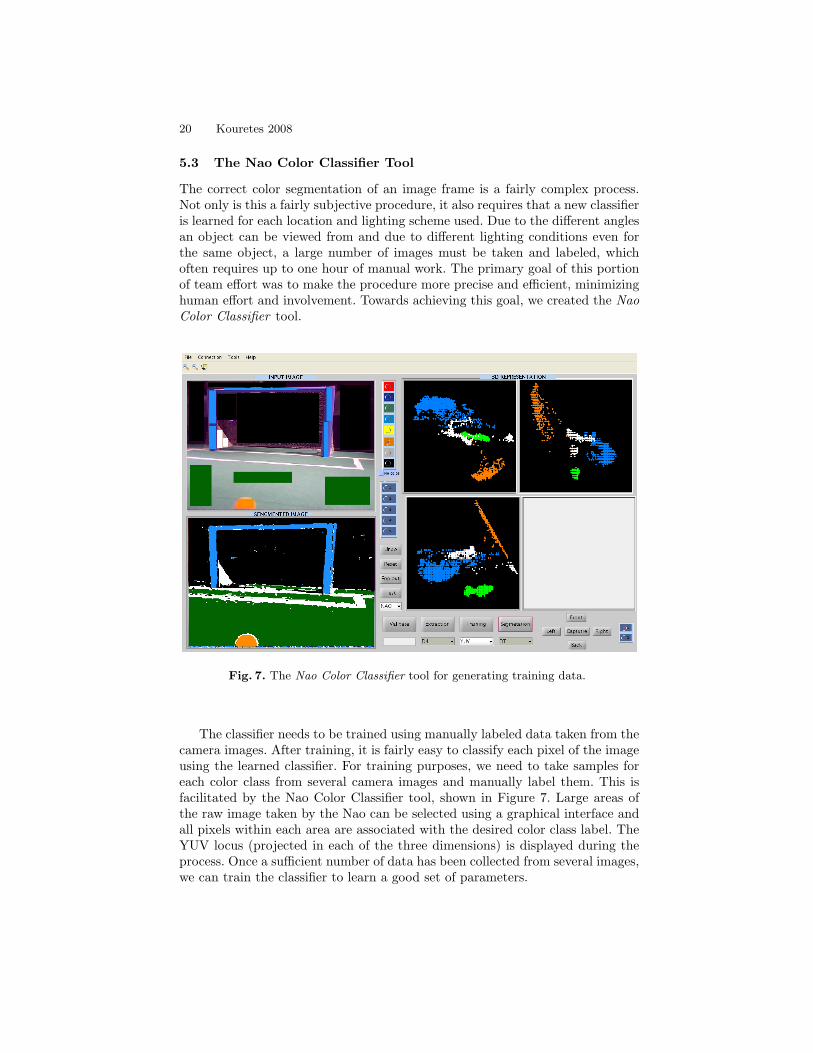
The correct color segmentation of an image frame is a fairly complex process.Not only is this a fairly subjective procedure, it also requires that a new classifieris learned for each location and lighting scheme used. Due to the different anglesan object can be viewed from and due to different lighting conditions even forthe same object, a large number of images must be taken and labeled, whichoften requires up to one hour of manual work. The primary goal of this portionof team effort was to make the procedure more precise and efficient, minimizinghuman effort and involvement. Towards achieving this goal, we created the NaoColor Classifier tool.
Fig. 7. The Nao Color Classifier tool for generating training data.
The classifier needs to be trained using manually labeled data taken from thecamera images. After training, it is fairly easy to classify each pixel of the imageusing the learned classifier. For training purposes, we need to take samples foreach color class from several camera images and manually label them. This isfacilitated by the Nao Color Classifier tool, shown in Figure 7. Large areas ofthe raw image taken by the Nao can be selected using a graphical interface andall pixels within each area are associated with the desired color class label. TheYUV locus (projected in each of the three dimensions) is displayed during theprocess. Once a sufficient number of data has been collected from several images,we can train the classifier to learn a good set of parameters.

Technical University of Crete 21
Figure 8 demonstrates our color segmentation method. A decision-tree clas-sifier has been trained under the N1 scheme using over 50,000 training examplesby labeling various regions in images taken by the robot camera. This moderatenumber of training data works well in avoiding under- and over-fitting. Similarly,another decision-tree classifier has been training under the N5 scheme using over100,000 training examples; the increase in the number of training data is neces-sary given the increase in the number of input attributes. The segmented imagefor each of these two classifiers is shown in Figure 8. In either case, the colorsof interest have correctly been identified, however the N5 scheme seems to yieldsomewhat better results than the N1 scheme.
Fig. 8. Original image and color segmented images (N1 and N5 schemes).
5.4 Image Enhancement
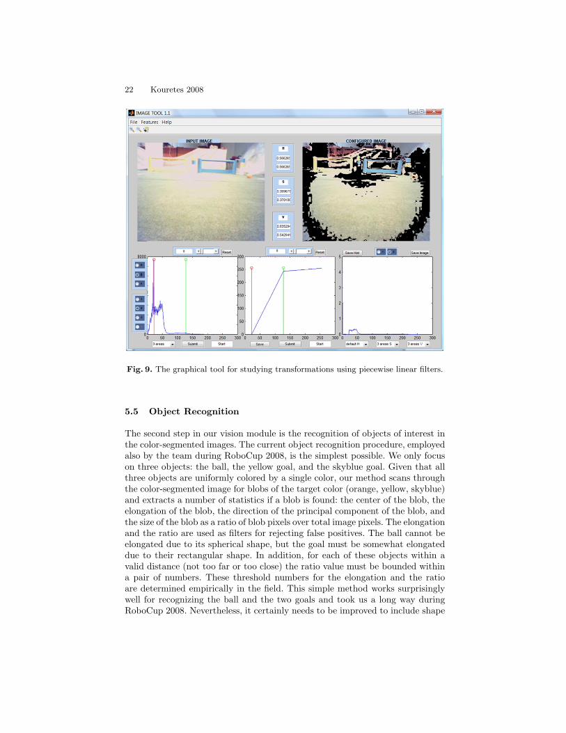
Past experience has shown that a failure in the color segmentation procedure canbe catastrophic for the robot team. Therefore, we have studied the possibilityof applying complex transformations on the raw camera image with the goal ofachieving best color separation which in turn will allow for robust color segmen-tation. To this end, we have developed a couple of tools for studying images inRGB, YUV, and HSI formats. In particular, the first tool analyzes the imageand displays histograms for each color component (R/G/B, Y/U/V, or H/S/I).Furthermore, it allows the direct additive or multiplicative modification of allR/G/B, Y/U/V, or H/S/I values and the results are displayed on screen in realtime. The other tool enables the study of the effect of various transformationson the image when applying piece-wise linear filters to each of the three colordimensions (Figure 9). The range of each dimension can be split into any numberof intervals and an arbitrary linear transformation can be applied to each one ofthem. The resulting non-linear transformation of the image is displayed in realtime on screen. The final version of these tools will be incorporated into the NaoColor Classifier tool to allow the user to use the transformed images as input tothe color segmentation process and observe the combined result.
22 Kouretes 2008
Fig. 9. The graphical tool for studying transformations using piecewise linear filters.
5.5 Object Recognition
The second step in our vision module is the recognition of objects of interest inthe color-segmented images. The current object recognition procedure, employedalso by the team during RoboCup 2008, is the simplest possible. We only focuson three objects: the ball, the yellow goal, and the skyblue goal. Given that allthree objects are uniformly colored by a single color, our method scans throughthe color-segmented image for blobs of the target color (orange, yellow, skyblue)and extracts a number of statistics if a blob is found: the center of the blob, theelongation of the blob, the direction of the principal component of the blob, andthe size of the blob as a ratio of blob pixels over total image pixels. The elongationand the ratio are used as filters for rejecting false positives. The ball cannot beelongated due to its spherical shape, but the goal must be somewhat elongateddue to their rectangular shape. In addition, for each of these objects within avalid distance (not too far or too close) the ratio value must be bounded withina pair of numbers. These threshold numbers for the elongation and the ratioare determined empirically in the field. This simple method works surprisinglywell for recognizing the ball and the two goals and took us a long way duringRoboCup 2008. Nevertheless, it certainly needs to be improved to include shape
Technical University of Crete 23
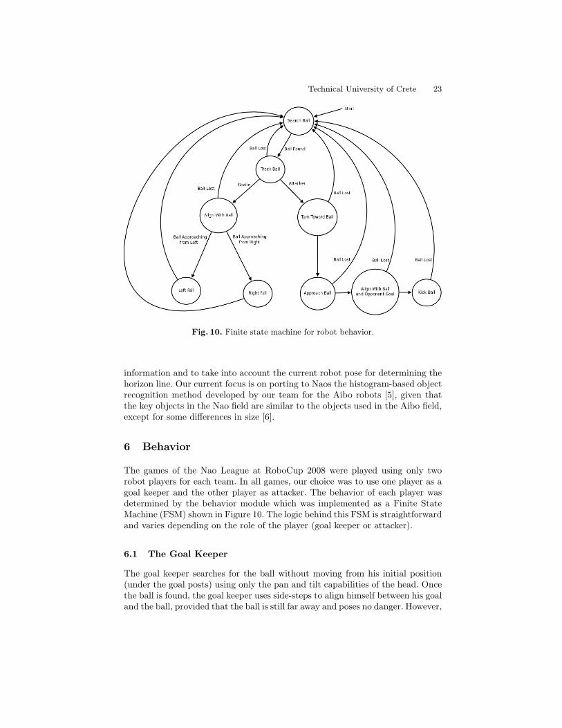
Fig. 10. Finite state machine for robot behavior.
information and to take into account the current robot pose for determining thehorizon line. Our current focus is on porting to Naos the histogram-based objectrecognition method developed by our team for the Aibo robots [5], given thatthe key objects in the Nao field are similar to the objects used in the Aibo field,except for some differences in size [6].
6 Behavior
The games of the Nao League at RoboCup 2008 were played using only tworobot players for each team. In all games, our choice was to use one player as agoal keeper and the other player as attacker. The behavior of each player wasdetermined by the behavior module which was implemented as a Finite StateMachine (FSM) shown in Figure 10. The logic behind this FSM is straightforwardand varies depending on the role of the player (goal keeper or attacker).
6.1 The Goal Keeper
The goal keeper searches for the ball without moving from his initial position(under the goal posts) using only the pan and tilt capabilities of the head. Oncethe ball is found, the goal keeper uses side-steps to align himself between his goaland the ball, provided that the ball is still far away and poses no danger. However,

24 Kouretes 2008
if the ball is close and approaches from the left or the right side (indicated bythe head pan exceeding some threshold value), then the goal keeper initiates aleft or a right fall respectively. This action protects the goal on either side andupon completion brings the robot back to its initial position from where theFSM restarts.
6.2 The Attacker
The attacker search for the ball using a combination of head pan and tilt motions(to cover the effective visual field), rotation in place (to cover all angles aroundthe current position), bending (for checking the area near his feet), and forwardor backward walk (for repeating the search in another location). As long asthe ball is not found this search procedure continues, however if the own goalbecomes visible the player will prefer to walk towards it as opposed to walktowards the opponent goal; the purpose is to get behind the ball to initiate anew attack on the opponent once the opportunity appears.
Once the ball is found, the attacker turns towards the ball using rotationin place and starts approaching it by straight walk. Below a certain distancethreshold, approaching the ball is performed in small steps with frequent bendingof the body to ensure that the ball is still there. When the ball is close to his feet,the Attacker uses side-steps to align the ball with the kicking leg. Upon successfulcompletion of this step, a kick is initiated and the procedure is repeated.
7 Bipedal Walk
7.1 Walk Engine
Stable walk on the Nao robots is probably the grand challenge for all participat-ing teams. Our efforts to produce our own walk engine led in little progress, there-fore quite early in the process we decided to use the proprietary walk functionsprovided by Aldebaran in order to invest our time on other, equally important,problems for which no solution was provided. The provided walk functions, how-ever, could be used as an off-the-self solution. It turns out that the various walkparameters need careful tuning separately for each surface, for each robot, andfor each walk type. Despite the tedious process of manual tuning, by using somesimple Ruby scripts we managed to derive a separate set of good parametersfor each one of our robots and for each one of the walk types we used (forward,backward, turning, side-step) on the carpet of the RoboCup 2008 fields. Thesuccess of this choice reflects on the fact that during all the games we played atRoboCup, only once did a robot lost balance and fell on the ground. At all othertimes, walk was stable.
7.2 Motion Parametrization
The first step in our endeavor to control the robot in a principled way is toparametrize the motion primitives of the robot. This involves defining a set of
Technical University of Crete 25
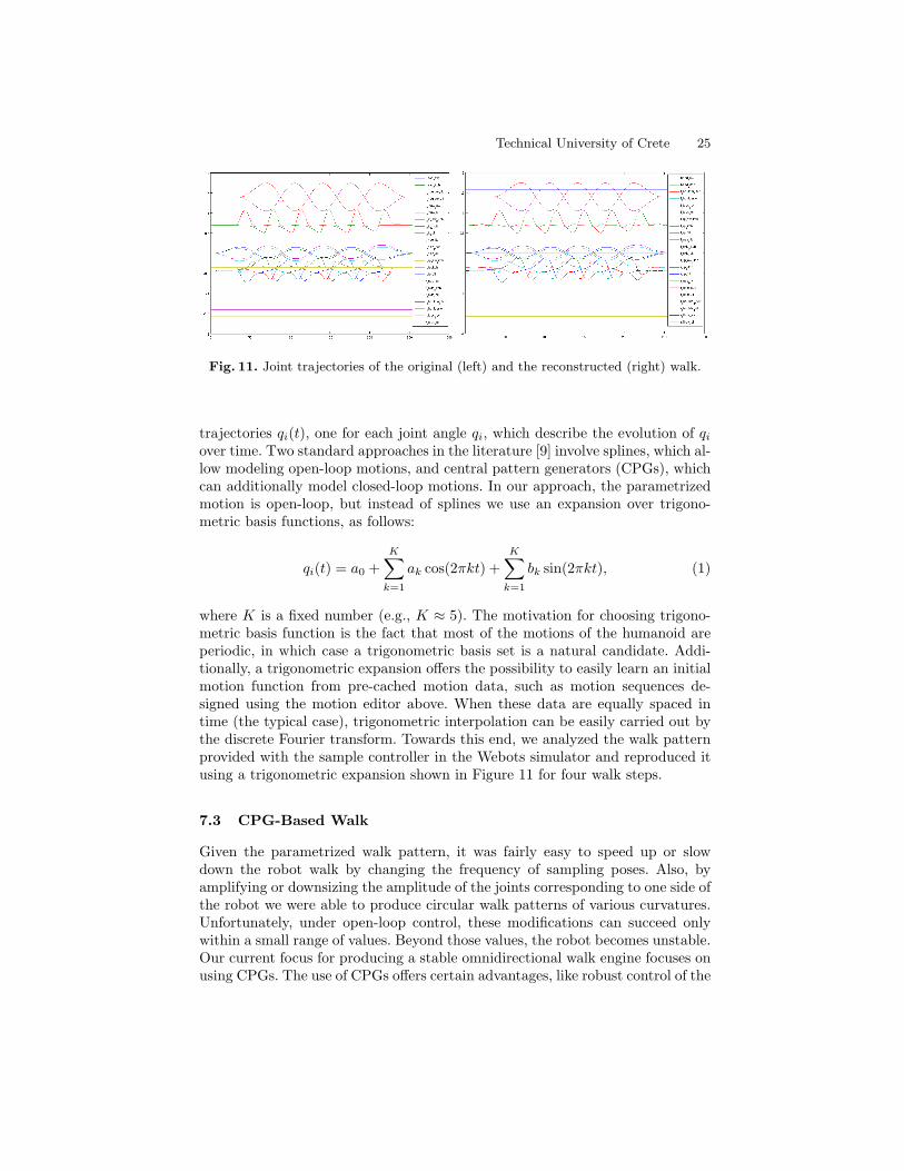
Fig. 11. Joint trajectories of the original (left) and the reconstructed (right) walk.
trajectories qi(t), one for each joint angle qi, which describe the evolution of qiover time. Two standard approaches in the literature [9] involve splines, which al-low modeling open-loop motions, and central pattern generators (CPGs), whichcan additionally model closed-loop motions. In our approach, the parametrizedmotion is open-loop, but instead of splines we use an expansion over trigono-metric basis functions, as follows:
qi(t) = a0 +K∑k=1
ak cos(2πkt) +K∑k=1
bk sin(2πkt), (1)
where K is a fixed number (e.g., K ≈ 5). The motivation for choosing trigono-metric basis function is the fact that most of the motions of the humanoid areperiodic, in which case a trigonometric basis set is a natural candidate. Addi-tionally, a trigonometric expansion offers the possibility to easily learn an initialmotion function from pre-cached motion data, such as motion sequences de-signed using the motion editor above. When these data are equally spaced intime (the typical case), trigonometric interpolation can be easily carried out bythe discrete Fourier transform. Towards this end, we analyzed the walk patternprovided with the sample controller in the Webots simulator and reproduced itusing a trigonometric expansion shown in Figure 11 for four walk steps.
7.3 CPG-Based Walk
Given the parametrized walk pattern, it was fairly easy to speed up or slowdown the robot walk by changing the frequency of sampling poses. Also, byamplifying or downsizing the amplitude of the joints corresponding to one side ofthe robot we were able to produce circular walk patterns of various curvatures.Unfortunately, under open-loop control, these modifications can succeed onlywithin a small range of values. Beyond those values, the robot becomes unstable.Our current focus for producing a stable omnidirectional walk engine focuses onusing CPGs. The use of CPGs offers certain advantages, like robust control of the

26 Kouretes 2008
joints and easy adjustment of walking speed and step length, but also severaldrawbacks, such as a high number of parameters that have to be configured.We expect to overcome the main drawback by using programmable CPGs [10]which can be trained using the provided walk. Programmable CPG’s are in facta network of CPGs that have the ability to reproduce a periodic signal after theyget trained from the signal itself. Each CPG in the network reproduces a specificfrequency component from the original signal. After training with the periodicjoint trajectories from the provided walk we can use a programmable CPG tocontrol each joint. In order to achieve synchronized movement of each leg we canconnect every programmable CPG with its predecessor in the kinematic chain. Inaddition, to keep the legs in phase we have to connect the CPGs of the hip joints.The CPGs collectively will produce the trajectory of the legs in the Cartesianspace and will make the robot walk. The stability issue can be addressed byadding some feedback to the CPG network and thus closing the loop. Thesefeedback signals can be both the FSR and the inertial unit readings. The firstprovide feedback for ground contact which is important for phase resetting, whilethe latter measures the tilt for both the lateral and the sagittal planes neededfor compensating disturbances.
8 Localization
Self-localization of the robots in the field is accomplished using Monte CarloLocalization with Particle Filters implementation. This module is still underdevelopment and is currently being tested on the Webots simulator (Figure 12).The belief of the robot is a probability distribution over the 3-dimensional spaceof (x, y, θ), where x, y are the robot coordinates on the field from a bird’s eyeview and θ is the orientation of the robot with respect to the line that crosses thecenter of the goals. The belief is represented approximately using a populationof particles. In order to perform belief update, it is necessary to obtain a motionmodel for the available high-level actions of the robot (walk, turn, etc.) and asensor model for its landmark perception capabilities (goal recognition) over the(x, y, θ) space.
We constructed a simple motion model P ((x′, y′, θ′)|(x, y, θ), a) for predictingthe probability distribution of the pose of the moving robot after each action a.Assuming that an action postulates that the robot moves a distance D in thedirection ω and rotates by an angle φ, this simple model first introduces additiveGaussian noise to D and ω
D′ = D +N(µD, σD)
ω′ = ω +N(µω, σω)
and then predicts the new posex′
y′
θ′
=
x+ cos(ω′ + θ) ∗D′
y + sin(ω′ + θ) ∗D′
θ + φ+N(µθ, σθ)

Technical University of Crete 27
Fig. 12. Graphical user interface for localization testing.
introducing also Gaussian additive noise to θ. Similarly, we have constructed asimple sensor model P (z|(x, y, θ)) which uses a zero mean Gaussian distributionto weigh more the particle i where the observation is close to the expectedobservation from that pose
wi =1√
(2πσr)e
− (ro − ri)2σ2
r
where r2i = (xi − xg)2 + (yi − yg)2 is the expected distance observation to somelandmark g located at (xg, yg) and ro is the observed distance.
In order to learn the parameters of the motion model we collected data usingthe Webots simulator by executing the same action (5 steps forward) 500 timesfrom the same initial pose and observing the resulting pose. The collected dataare shown in Figure 13. It is straightforward now to extract values for the missingparameters of the Gaussian noise.
Nevertheless, one can go beyond this simple motion model and try to learn-ing a motion model directly from the data. Figure 14 shows various ways ofapproximating directly the distribution of the data: univariate Gaussian, multi-variate Gaussian, mixture of Gaussians. In all cases, the result is satisfactory as

28 Kouretes 2008
0 0.1 0.2 0.3 0.4 0.5
−0.15
−0.1
−0.05
0
0.05
0.1
0.15
0.2
X (m)
Z (
m)
−0.15 −0.1 −0.05 0 0.050
50
100
150
200
Distance Error HistogramE mean:−0.017015 Deviation: 0.026239
−0.4 −0.2 0 0.2 0.40
50
100
150
200
Direction Error HistogramE mean:0.030486 Deviation: 0.097458
−1 −0.5 0 0.5 10
50
100
150
200
Rotation Error HistogramE Mean:0.005837 Deviation: 0.210791
Fig. 13. Learning the parameters of the motion model for the action “Walk straightfor 5 steps”.
shown by the overlayed data of all models. This experimental work is currentlyin progress for the sensor model.
Having both the motion and the sensor models, belief update is performedusing the Sampling Importance Resampling (SIR) particle filter algorithm:
– propagate the particles through the motion model– weight each particle using the sensor model, normalize if required– resample the particle population when depleted
For the resampling process, Selection with Replacement and Linear Time Re-sampling have been implemented. Given any population of particles, the player’spose is estimated as the robust mean of the weighted particles.
9 Skill Learning
A final aspect of our work involves the use of reinforcement learning (RL) forlearning good motion policies for the various robot tasks (walking, rotating in

Technical University of Crete 29
0 0.2 0.4
−0.2
−0.1
0
0.1
0.2
Data
0 0.2 0.4
−0.2
−0.1
0
0.1
0.2
Univariate
0 0.2 0.4
−0.2
−0.1
0
0.1
0.2
0.3Multivariate
0 0.2 0.4
−0.2
−0.1
0
0.1
0.2
Mix GAussian
0 0.1 0.2 0.3 0.4 0.5 0.6−0.15
−0.1
−0.05
0
0.05
0.1
0.15
Data < Univariate < Multivariate < Mix
StartDataUnivariateMultiVariateMix
Fig. 14. Learning directly a motion model for the action “Walk straight for 5 steps”.
place, ball kicking, etc.). Our approach is based on variations of the natural actor-critic (NAC) framework [9]. This approach allows estimating (by running severaltrial-and-error episodes) the gradient of the value function of the parametrizedmotion policy as a function of the motion parameters (the quantities ak and bkin eq. 1). Then, by following this gradient we eventually reach a (local) optimumof the motion policy. The attractive properties of the NAC framework are itsstability (convergence to a local optimum is guaranteed) and ease of implemen-tation.
For learning a ball kicking skill, we have implemented a dedicated module,which ensures that the robot maintains its balance while carrying out the kick-ing motion. Robot balance is achieved by monitoring the zero moment point(ZMP) [11], and ensuring that the ZMP remains within the support polygon ofthe ground foot of the robot during the motion. The latter is modeled as a Re-inforcement Learning (RL) problem [12]. In this formulation, the robot alwaysstarts from the same position and tries to kick the ball as quickly as possiblewithout losing its balance. This involves a trial-and-error procedure that even-tually converges to a near-optimal kicking policy.
More formally, in the RL formulation we define a parametrized stochasticpolicy that implements the kicking motion. The kicking motion involves a num-ber of joints (we have used four leg joints in our experiments), where the motionof each joint is characterized by a parametrized trajectory q(t) of the joint as afunction of time:
q(t) =∑k
(θk + εk)φk(t) = (θ + ε) · φ(t), (2)

30 Kouretes 2008
Fig. 15. Learned kick motion without falling.
where θ = (θk) is a vector of parameters (one vector θ for each joint), φk(t)are fixed basis functions (we have used Gaussian-like functions, but other basisfunctions can also be used), and εk are zero-mean Gaussian noise terms εk ∼N (0, σ2) that enforce exploration. This particular type of stochastic policy hasbeen suggested by Kober and Peters [13].
In each time step, an immediate reward signal r(t) is issued, which charac-terizes the quality of the trajectory and the balancing status of the robot. Inparticular, we used a reward function
r(t) = rkick(t) + rzmp(t), (3)
where the first term incorporates aspects of the trajectory that allow fast kick-ing (first and second derivatives of q(t), and the second term implements thebalancing constraint |xxmp| + |yzmp| < ε. The task is to locate a near-optimalvector of parameters θ that maximizes the expected return J(θ) = Eθ[r].
Kober and Peters [13] show how to update the parameters θ by trial and error,ensuring convergence to a local maximum of the expected return. In particular,starting with an initial value for θ, the robot follows the stochastic policy (2)and collects a set of trajectories ξ. The update rule is then:
θ := θ +
⟨ ∑Ht=0Qξtεξt
⟩ξ⟨ ∑H
t=0Qξt
⟩ξ
, where Qξt =H∑T=t
rξT . (4)
Here εξt and rξt denote respectively the realized noise term and the observedreward, at time step t of trajectory ξ. The brackets denote averaging over theset of collected trajectories, and H is the trajectory length.
Figure 15 shows the learned kick motion after 500 episodes of learning. Dur-ing the first episodes, almost all trials resulted in the robot falling on the ground.Note the learned policy controls only the joints of the kicking leg, while the robotis passively standing on the other leg; this is an extremely unstable configura-tion and the swinging motion of the kicking leg can easily cause a fall. Thispreliminary result is encouraging and may prove useful in the future, especiallyif combined with closed-loop control, for transferring to the real robot.
Alternatively, the problem of learning skills on a high-dimensional humanoidrobot could be viewed as a multi-agent problem, whereby each agent controls asingle joint of the robot and all controlling agents collaborate with each othertowards a common goal. Recent independent research work by the team leadershas led to extensions of classic reinforcement learning algorithms to collaborative
Technical University of Crete 31
multi-agent learning where many agents learn to collaborate as a team [14, 15].The scaling properties of these algorithms through exploitation of domain knowl-edge make them attractive for learning sophisticated motion skills for the Naorobot. While the large number of degrees of freedom on the Aibo imply a hugejoint action space, this obstacle could be overcome by appropriate factorizationof the representation on the basis of joint proximity on the robot body. Undersuch a learning scheme, the ankle joints of the left leg may need to “talk” to theknee joints of the same leg, but need not communicate directly with the anklejoints of the right leg. The resulting tree-like factorizations will make the abovementioned learning algorithms even more efficient as the required operations canbe completed in polynomial time.
10 Conclusion
This research report covers all aspects of the work done by the members of TeamKouretes on the Nao robots in the context of the Standard Platform League ofthe RoboCup 2008. A large portion of this work is still ongoing, therefore sev-eral ideas and design choices are constantly under revision. Interested RoboCupteams are welcome to use the material included in this report. Some parts of theteam’s code which may be useful to other teams will soon be released on theteam’s web site (www.kouretes.gr). Comments, suggestions, corrections, etc.from readers and users are always welcome.
We are looking forward to an even better Standard Platform League atRoboCup 2009 in Graz, Austria!
Acknowledgements
Team Kouretes would like to thank the administration of the Technical Univer-sity of Crete for funding their travel to RoboCup 2008. The research efforts ofthe team were partially supported by the European Marie-Curie InternationalReintegration Grant MCIRG-CT-2006-044980 awarded to M. G. Lagoudakis.
References
1. Kitano, H., Asada, M., Kuniyoshi, Y., Noda, I., Osawa, E., , Matsubara, H.:Robocup: A challenge problem for AI. AI Magazine 18(1) (1997) 73–85
2. Gouaillier, D., Blazevic, P.: A mechatronic platform, the Aldebaran robotics hu-manoid robot. 32nd IEEE Annual Conference on Industrial Electronics, IECON2006 (November 2006) 4049–4053
3. Michel, O.: Webots: Professional mobile robot simulation. Journal of AdvancedRobotics Systems 1(1) (2004) 39–42
4. Spitzak, B., Sweet, M., Earls, C.P., Melcher, M.: The Fast Light Toolkit v. 1.3Programming Manual
5. Volioti, S.: Histogram-based visual object recognition for the 2007 robocup four-legged league. Diploma thesis, Technical University of Crete, Chania (2008)

32 Kouretes 2008
6. RoboCup Technical Committee: Robocup standard platform league (Nao) rulebook (2008)
7. Iocchi, L.: Robust color segmentation through adaptive color distribution trans-formation. In: RoboCup Symposium. (2006) 287–295
8. Quinlan, R.J.: C4.5: Programs for Machine Learning. Morgan Kaufmann (1993)9. Peters, J., Schaal, S.: Reinforcement learning of motor skills with policy gradients.
Neural Networks 22 (2008) 682–69710. Righetti, L., A.J., I.: Programmable central pattern generators: an application to
biped locomotion control. In: Proceedings of the 2006 IEEE International Confer-ence on Robotics and Automation. (2006) 1585–1590
11. Vukobratovic, M., Juricic, D.: Contribution to the synthesis of biped gait. IEEETransactions on Biomedical Engineering 16(1) (1969) 1–6
12. Sutton, R.S., Barto, A.G.: Reinforcement Learning: An Introduction. The MITPress (1998)
13. Kober, J., Peters, J.: Policy search for motor primitives in robotics. In: Advancesin Neural Information Processing Systems 22 (NIPS 2008), Vancouver, CA (2008)
14. Kok, J.R., Vlassis, N.: Collaborative multiagent reinforcement learning by payoffpropagation. Journal of Machine Learning Research 7 (2006) 1789–1828
15. Guestrin, C., Lagoudakis, M.G., Parr, R.: Coordinated reinforcement learning.In: Proceedings of the Nineteenth International Conference on Machine Learning.(2002) 227–234


![Montreal, Canada Dutch Nao Team - UvA · serviced Nao V3 robots. The quali cation video is available at our YouTube channel1. A research report [1], describing the technical details](https://static.fdocuments.us/doc/165x107/5f208b17e7c3c85506720b3f/montreal-canada-dutch-nao-team-uva-serviced-nao-v3-robots-the-quali-cation-video.jpg)


