
Koshland Integrated Natural Science Center - engr.psu.edu · 1 Koshland Integrated Natural Science...
44
Koshland Integrated Natural Science Center The Pennsylvania State University Department of Architectural Engineering Christopher J. Shelow Senior Thesis Study Structural Spring ‘06 Haverford College Haverford, PA
Transcript of Koshland Integrated Natural Science Center - engr.psu.edu · 1 Koshland Integrated Natural Science...

Koshland Integrated Natural Science Center
The Pennsylvania State University Department of Architectural Engineering
Christopher J. Shelow Senior Thesis Study
Structural Spring ‘06
Haverford College Haverford, PA

Table of Contents
Thesis Abstract ................................................................................... 1 Executive Summary............................................................................ 2 Design Professionals ......................................................................... 3 Acknowledgements ............................................................................ 4 Introduction & Building Background................................................ 5
Thesis Proposal ................................................................................ 10 Structural Design.............................................................................. 13 Gravity System ......................................................................... 17 Lateral System.......................................................................... 21 Connection Design ................................................................... 22 Construction Management Breadth Studies.................................. 24 Existing System ........................................................................ 25 Proposed System ..................................................................... 26 Conclusion ................................................................................ 27 Mechanical Breadth Study............................................................... 28 Existing System & Layout ......................................................... 29 Proposed System & Layout ...................................................... 29 Conclusion ................................................................................ 30 Findings & Conclusions................................................................... 31 References ........................................................................................ 33
Appendices...........................................................................................I

1
Koshland Integrated Natural Science Center
Haverford College, Haverford, PA Project Overview
• Total Square Footage : 185,423 • 4-story Educational Building • Spaces include Laboratories, Classrooms, & Offices • Total Project Cost: $42.6 Million
Project Team • Owner: Haverford College (Physical Plant) • Architect: Ayers/Saint/Gross (ASG) Architects & Planners • Engineer: CUH2A • General Contractor/CM: Skanska USA Building, Inc. • Laboratory Planner: Earl Walls Associates
Architecture • Designed to be a “laboratory of the 21st century” • Spiral Staircase as central core of the building with
cantilevered stairs • Directly connected to the existing Sharpless and
Hilles Halls
Structural • Superstructure: Precast Concrete Framing • Foundation: CMU Block Walls/Retaining Walls • Floor: 10” Hollow Core Precast Planks w/2” topping • Envelope: Stone & Brick Façade/White Precast Concrete Panels • Roof: Steel Framing w/Metal Deck
Mechanical • Energy wheels create “space-neutral” air • Fan-Coil Units maintain temperature controlled rooms • 110 fume hoods operate at 900 cfm exhaust in labs • Water stored in two 240 ton chillers
Lighting
• Variations of direct and indirect lighting are used in all communal spaces
• Photocells and Relay-based lighting In lobby
http://www.arche.psu.edu/thesis/eportfolio/current/portfolios/cjs1031/

Executive Summary

Koshland Integrated Chris Shelow Natural Science Center Structural M. Kevin Parfitt Haverford College Final Report Haverford, Pennsylvania Spring ‘06
2
Executive Summary
The Koshland Integrated Natural Science Center, located in Haverford, Pennsylvania, is
four story laboratory building and is a new edition to the Haverford College campus. The
building is comprised of laboratory, classroom, and office spaces as well as numerous
communal areas. The KINSC is directly connected to the two existing structures,
Sharpless and Hilles Halls, but is very distinctive in its architecture and engineering. The
existing structural system is primarily precast concrete, including the floor system, the
framing, and the lateral system.
This report provides an in-depth study on the comparison between the existing precast
concrete system and a proposed structural system of steel framing with composite
concrete slab on metal deck as the proposed floor system. The proposed lateral system
consists of steel braced frames. The design of the structural system was performed with
the use of the RAM Structural System program. The lateral system was designed with
the aid of STAAD Pro. The purpose of this study is to examine any possible benefits that
could come from using the proposed system over the existing system.
Also included in this report are two breadth studies, in the areas of Construction
Management and Mechanical emphasis. The C.M. breadth directly correlates to the
structural depth study in that it compares the existing and proposed systems in a cost
analysis and project schedule. The Mechanical breadth study involves the investigation
of the thermal resistance between floors of both the existing and proposed systems due to
the strict temperature controls necessary for the laboratory areas in the building.
Ultimately, the purpose of this report is to decisively indicate which structural system
proves to be more efficient. The results are based solely on the investigations performed
within this thesis study. The conclusions of this thesis study project that the proposed
steel system is more efficient than the existing system in terms of cost and schedule. In
no way was the purpose of this report to undermine the decisions made by the engineers
of the existing design.

Koshland Integrated Chris Shelow Natural Science Center Final Report
3
Design Professionals
Owner:
Haverford College (Physical Plant)
Architect:
Ayers/Saint/Gross (ASG) Architects & Planners
Engineer:
CUH2A
General Contractor/CM:
Skanska USA Building, Inc.
Laboratory Planner:
Earl Walls Associates

Acknowledgements

Koshland Integrated Chris Shelow Natural Science Center Final Report
4
Acknowledgements
Throughout this past year, there were many groups and individuals who played important
roles as far as the completion of this thesis study. I would like to take this opportunity to
express my gratitude to everyone who helped to make my thesis study a success. First
and foremost, I would like to especially thank John Diaz and Ron Tola at Haverford
College for allowing me to use the Koshland Integrated Natural Science Center as the
subject for my thesis. It proved to be a very interesting and educational project to study.
Also, I would like to thank Sam Rozycki and CUH2A for donating the drawing sets for
the KINSC, offering any relevant information pertaining to the project, and also for
answering the numerous questions I had asked throughout the entire study. Furthermore,
I would like to extend a tremendous thank you Valerie Gillespie for helping me to get
started altogether. She definitely helped get the ball rolling. I would also like to thank
Dr. Parfitt and Dr. Hanagan for directly answering an onslaught of questions over the past
two semesters, and the entire Penn State AE department faculty who offered suggestions,
patience, and understanding throughout the duration of my thesis study.
On a more informal note, I would like to also thank a number of my friends and family
members who helped make this possible. Sincere thank you to all of my AE friends who
offered help throughout this study and helped maintain my sanity this year. I would like
to also thank my mom, dad, and brother for their patience, understanding, and support
throughout this past year. And last but not least, I would like to thank Abby Roth for her
relentless support and encouragement that lasted the duration of my thesis study.
Again, thank you all…

Introduction & Building Background
Koshland Integrated Chris Shelow Natural Science Center Final Report
5
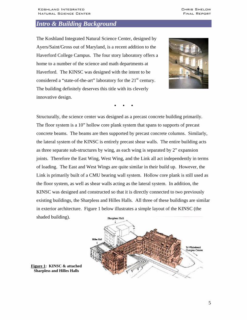
Intro & Building Background
The Koshland Integrated Natural Science Center, designed by
Ayers/Saint/Gross out of Maryland, is a recent addition to the
Haverford College Campus. The four story laboratory offers a
home to a number of the science and math departments at
Haverford. The KINSC was designed with the intent to be
considered a “state-of-the-art” laboratory for the 21st century.
The building definitely deserves this title with its cleverly
innovative design.
• • •
Structurally, the science center was designed as a precast concrete building primarily.
The floor system is a 10” hollow core plank system that spans to supports of precast
concrete beams. The beams are then supported by precast concrete columns. Similarly,
the lateral system of the KINSC is entirely precast shear walls. The entire building acts
as three separate sub-structures by wing, as each wing is separated by 2” expansion
joints. Therefore the East Wing, West Wing, and the Link all act independently in terms
of loading. The East and West Wings are quite similar in their build up. However, the
Link is primarily built of a CMU bearing wall system. Hollow core plank is still used as
the floor system, as well as shear walls acting as the lateral system. In addition, the
KINSC was designed and constructed so that it is directly connected to two previously
existing buildings, the Sharpless and Hilles Halls. All three of these buildings are similar
in exterior architecture. Figure 1 below illustrates a simple layout of the KINSC (the
shaded building).
Figure 1: KINSC & attached Sharpless and Hilles Halls

Koshland Integrated Chris Shelow Natural Science Center Final Report
6
Typical elevation during the construction of the KINSC
With indifference to the majority of the KINSC, the roofs of the East and West Wings
were designed as steel roofs. They were designed and constructed as steel bent frames
with their own braced frame systems. The bent frames allow the fourth floor to be
utilized as a mechanical space in the East Wing and a Library mezzanine in the West
Wing. In addition, the structure below grade, including the foundation, the ground floor,
and the first floor framing, is strictly precast concrete. This includes footings, retaining
walls, and precast piers. The ground floor is slab on grade.
As stated previously, the East and West Wings are similar in their layout. A typical
exterior bay in the East and West Wings is 31’-6” X 21’-0” and a typical interior bay of
13’-8” X 21’-0”. As for the Link, essentially there are no interior columns or beams.
The precast hollow core planks span
from one exterior CMU bearing wall
to the other in the N-S direction.
There are typically three different sizes
of columns used for structural framing
throughout the building. Columns
sized as 16”x16” and 20”x20” were
used fluently throughout the typical
floor. There are columns sized at
18”x36” used in certain specified
areas such as locations where the loading is increased significantly. Precast concrete
beams span between the exterior precast columns creating the perimeter of the East and
West Wings. These beams are typically sized as 24”x12”. Then there are precast beams
that span between the interior precast columns generally in the N-S direction for the East
and West Wings. The typical sizes of the interior beams are 24”x12” or 20”x16”
depending on location. As for the flooring, 10” hollow core planking with a 2” topping
slab generally spans in the E-W direction for the East and West Wings. In the Link, the
same hollow core plank with topping spans in the N-S direction from exterior bearing
wall to exterior bearing wall. The exterior bearing walls ranged in thickness from 8” to
14” depending on the story level. The lateral system of the KINSC is strictly a shear wall
system. The East and West Wings each account for two 8” precast shear walls spanning
Koshland Integrated Chris Shelow Natural Science Center Final Report
7
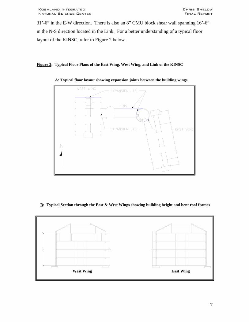
31’-6” in the E-W direction. There is also an 8” CMU block shear wall spanning 16’-6”
in the N-S direction located in the Link. For a better understanding of a typical floor
layout of the KINSC, refer to Figure 2 below.
Figure 2: Typical Floor Plans of the East Wing, West Wing, and Link of the KINSC
A: Typical floor layout showing expansion joints between the building wings
B: Typical Section through the East & West Wings showing building height and bent roof frames
West Wing East Wing

Koshland Integrated Chris Shelow Natural Science Center Final Report
8
C: Typical Floor Plan – East Wing
D: Typical Floor Plan - Link

Koshland Integrated Chris Shelow Natural Science Center Final Report
9
E: Typical Floor Plan – West Wing
F: Typical 10” Hollow Core Plank with 2” Topping Slab
10”
2” Topping Slab
Thesis Proposal
Koshland Integrated Chris Shelow Natural Science Center Final Report
10
Proposal
Problem Statement:
From previous investigation, it became apparent that the existing design of the Koshland
Integrated Natural Science Center is an incredibly efficient design on several levels. The
design expertise of the professionals who were involved in the KINSC is quite prevalent
and was expected to be so. As results of earlier research, the design of the framing
members, floor system, and lateral system all exceeded design requirements as per
BOCA 93 and ASCE 07. Also, the design of the KINSC meets all code requirements
concerning physical restrictions on the building by a considerable amount. Therefore,
when considering an alternative design to this building, the final decision did not easily
come about. However, I would like to further investigate some other options. I would
like to consider redesigning the structural system of the existing KINSC at an attempt to
find an equally effective or more efficient system.
To determine whether a different system is more efficient, it will be compared to the
existing system in a number of categories. These categories will include, but are not
limited to being the most cost effective, ease of constructability, most efficient
construction schedule, and material availability. This proposal will research an
alternative system that could possibly prove to be a more viable solution than the existing
system in any of these categories.
Solution Process:
As a viable solution to an alternate structural system for the KINSC, the first
modification to be considered is altering the framing of the typical floors to an entire steel
frame. A transition from precast concrete to steel framing seems to be a logical
comparison for this structure. This will consequently affect aspects such as CM issues
like schedule and cost, perhaps the mechanical system, and possibly architecture. In
addition, since the controlling lateral load case is seismic, changing the building framing
to steel may reduce those loads due to a lighter overall building weight. A second
adjustment will be to change the floor system from hollow core planks to a composite
floor system while maintaining a similar floor depth and similar spans. As confirmed by
an earlier study, a full composite floor system is a reasonable option for this building.
Koshland Integrated Chris Shelow Natural Science Center Final Report
11
Furthermore, I would like to change the lateral force resisting system to a braced frame
system. The purpose of making these alterations to the structure is simply to investigate
the overall affects they have could have on the project, in anticipation of positive results.
All relative structural elements of the building will have to be considered throughout this
alternate design. This includes the foundation, floor systems, beams, columns, fire
protection, interior and exterior walls, and the roof. Obviously, since the redesign
incorporates a different primary material for the building, in this case, steel, the sizes of
basically every member will be altered. This, in return could give cause for the layout of
the structural members to change as well. The floor spans and location of the floor
framing members will remain unchanged where it is possible. When dealing with the
lateral system, braced frames will take the place of shear walls to distribute the lateral
loads that act on the structure. Location of these steel braced frames will be carefully
decided to possibly offer a more efficient lateral load resisting system. Some structural
aspects will remain the same. For instance, the expansion joints found throughout the
building will remain a part of the redesign to maintain the independent behavior of the
three sections of the building. The precast piers in the basement, retaining walls, and
footings will all remain the same. Since the proposed structure will be composed of steel,
the overall building weight will decrease. Therefore the existing size of footings, piers,
and walls below grade will be sufficient to support the new loads. Also, the roof of the
East and West Wings will remain the same as the existing system. This is the case
because the existing roof systems are currently steel bent frames which will coincide
nicely with the proposed steel framing system of the remainder of the building. Lastly,
the central stairwell will not be altered in design. Due to an innovative structural design,
the stairs cantilever out of the exterior wall of the stair case as they spiral upward. For
the purpose of maintaining the cantilevered stairs, no change in structural design will be
implemented. The design results of this alternative system will be thoroughly compared
to the design of the existing system with hopes of proving to be a more viable solution.
The use of RAM Structural System will most likely be the primary means of computer
design for this study of an alternative system. A 3D model of the KINSC will be created
in RAM and all steel structural members will be sized according to the calculated gravity
loads that will be applied to the structure. As for the design of the lateral system, a

Koshland Integrated Chris Shelow Natural Science Center Final Report
12
different program besides RAM may be utilized. A reliable option for the design of the
lateral system is STAAD Pro. The use of STAAD would allow for the braced frames to
be designed and analyzed individually. All aspects of the steel design will be based on
the Manual of Steel Construction, Load and Resistance Factor Design, 3rd Edition. Also,
all concrete design will be in accordance with the ACI-02 code, and all lateral loads will
be based on the ASCE7-02 regulations. The IBC 2003 will be followed strictly
throughout the design. Based on the results from the RAM and STAAD designs, the
most efficient structural system can be determined.
Layout of entire complex – KINSC, Sharpless, and Hilles Halls

Structural Depth Study

Koshland Integrated Chris Shelow Natural Science Center Final Report
13
Structural Depth Study
Design Criteria:
The following information pertains to building codes used throughout this depth study
and the overall design considerations for the proposed structural system:
Code Basis: 2003 International Building Code (IBC) ASCE 7 – 02 AISC LRFD, 3rd Edition
Design Considerations: Structural System Cost Construction Schedule
Gravity Loads:
The following gravity loads were used consistently throughout the design of the proposed
steel structural system. Many of the loads were maintained from the design of the
existing precast concrete system.
Table 1: Gravity Loads for Proposed Design
Location Load Description Load (psf)Roof Ground Snow Load 30Floor Typical 100
Libraries 300Lobbies/Corridors/Entrances 100Stairs 100Mechanical Room 125Storage 125
Live Loads
Location Load Description Load (psf)Roof Ceiling 5
MEP 10Roofing & Insulation 8Deck & Sheathing 5Slate Roofing 10Total 38
Floor Ceiling 5MEP 104" Composite Slab on Deck 48Partitions - 6" lite wt. CMU 30Total 93
Dead Loads

Koshland Integrated Chris Shelow Natural Science Center Final Report
14
Typical Floor Layout:
One main objective kept in sight throughout this structural study, was the intent to have
the layout of the floor plan remain unchanged. This was viewed as a somewhat crucial
objective due to the fact that the laboratories required large spaces with relatively open
floor plans. Ergo, the typical bay size of 31’-6” by 21’-0” as used in the existing system,
was utilized for the proposed steel system as well. The redesign of the KINSC also
maintained the floor-to-floor height of 13’. In the East and West Wings I chose to have
the girders spanning in the E-W direction as opposed to the N-S direction, in which the
existing design entails. This decision was made to allow for a more typical spacing of the
beams across the entire floor. The dimensions of the bays in the N-S direction vary more
often than the dimensions in the E-W direction. Therefore, from a constructability
standpoint, in terms of cost and schedule, the repetition in beam sizes and spacing can be
viewed as beneficial. A typical floor layout of the redesigned KINSC can be viewed
below in Figure 3.
Figure 3A: Typical layout of steel
framing – West Wing
A B C C.1D EF G
1
2
3
4
5
6
7
8
8.1
9
Koshland Integrated Chris Shelow Natural Science Center Final Report
15
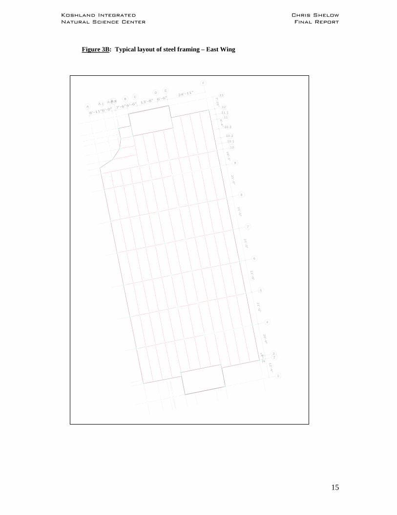
Figure 3B: Typical layout of steel framing – East Wing
AA.1 A.2A.3A.4
BC
DE
F
1
23
4
5
6
7
8
9
10
10.1
10.2
10.3
11
11.1
12
13

Koshland Integrated Chris Shelow Natural Science Center Final Report
16
Figure 3C: Typical layout of steel framing – Link
ABC
DEF
GHI
JKL
MN
OP
P.1 QQ
.1R
R.1
ST
1 2 2.1 3 3.1
3.2 4

Koshland Integrated Chris Shelow Natural Science Center Final Report
17
Composite Slab Design:
For the design of the composite concrete slab, the use of the Wheeling deck catalog was
implemented. Using the calculated loads for the structure, and the typical span between
beams of approximately 6.5’, a 1.5 SB normal weight composite deck was selected.
Furthermore, a 4” composite concrete slab was assumed for the design of the floor
system. The reinforcing for the slab on deck was chosen to be 6X6 – W1.4XW1.4
welded wire fabric. Shear studs of ¾” diameter with a length of 4” were selected to
ensure the composite action. The selected deck, slab, and stud sizes were inputted into
the RAM structural program for the design of the steel structure. Refer to Appendix A
for deck information and load calculations.
• • •
Structural Steel System – Gravity Loading:
To begin the design of the steel framing due to gravity
loads, a model of the KINSC was created in RAM. Due to
the multiple expansion joints found throughout the
building, separating the KINSC by wing, three individual
models were made in RAM. Each one of these models
represents a wing. The following steps were repeated for
each of the three models created, using the loads and building information corresponding
to the proper wing. The first step in creating the model was setting up the building grid.
Once the grid was laid out, the columns were placed. It was important to ensure the
columns were arranged with the correct orientation to allow for weak or strong axis
bending. Following the layout of the columns, the steel beams and girders were placed.
All beams, girders, and columns were W-shapes. Once the framing members were all
laid out, the deck, slab, and shear studs were selected and applied over the floor framing.
The next step of the modeling process was the defining and placing of the corresponding
floor loads. After the application of the loads was completed, this process was repeated
for each of the four stories.

Koshland Integrated Chris Shelow Natural Science Center Final Report
18
The next step in the design process, following the modeling of the structure, was the steel
beam design. Initially, a design code for the steel design was selected. For this depth
study, the LRFD 3rd Edition was chosen. Next, RAM performed the design of all steel
beams based on the design code specified and the information from the model. The
designs of all beams were then obtained and recorded. The RAM output design values
for the beams were very reasonable.
The final step in the gravity design process was the column design. RAM performed a
gravity design of the steel columns based on the axial loads acting on the columns. The
columns were designed and sized based on the limitations found within the steel design
code specified. A number of the columns sizes were slightly increased to account for
uniformity or the possibility of increased loading. Several RAM design outputs,
including plans and designs, can be reviewed in Appendix B.
• • •
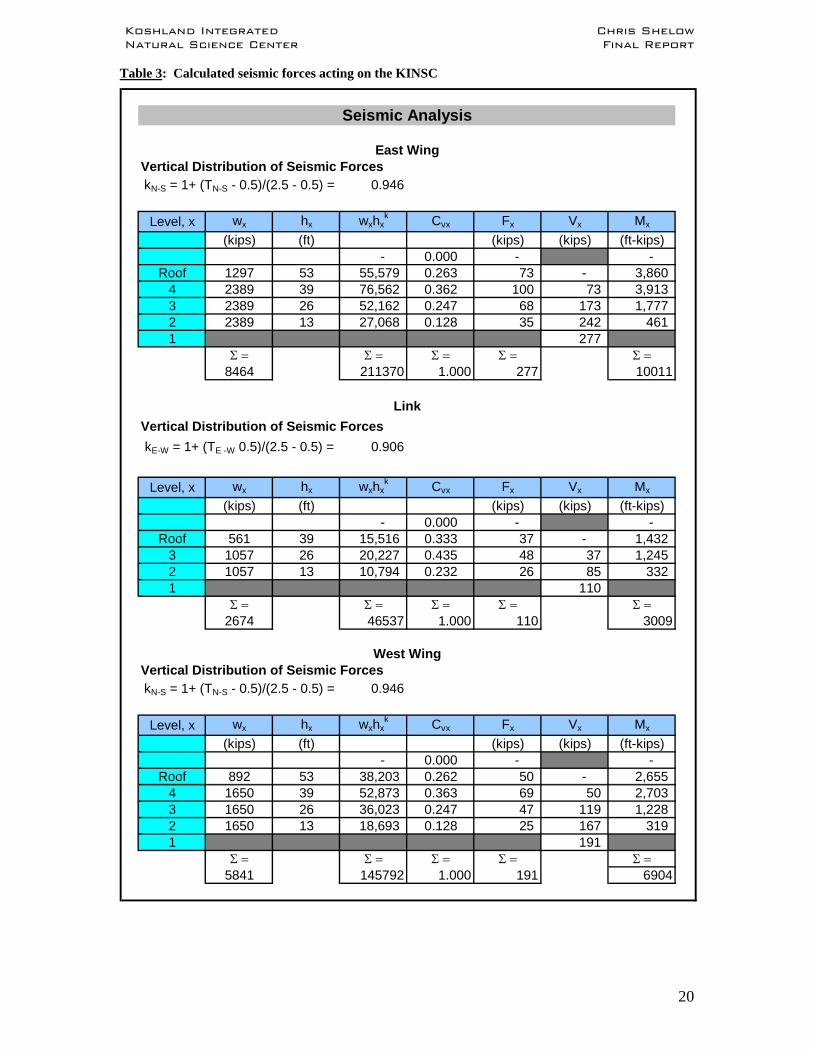
Lateral Loads:
For the design of the lateral force resisting system in the KINSC, forces due to wind and
seismic activity were calculated using the standards and methods in accordance with
ASCE 7-02. When analyzing the existing precast concrete system in an earlier study, it
was found that seismic forces acting on the building controlled over wind loads. With the
transition from the existing precast to the proposed steel system, the overall weight of the
structure would be decreasing. Therefore, it was not guaranteed that the proposed steel
design of the KINSC would be controlled by seismic forces. This being the case, the
lateral loads acting on the building, both wind and seismic, were recalculated, again
based on ASCE 7-02. The results concluded that seismic forces would again control of
wind loads acting on the building. The complete calculations for both lateral load cases
can be reviewed in Appendix C. For a summary of the seismic information pertaining to
the proposed design of the KINSC and the controlling seismic forces, see Tables 2 and 3
below.

Koshland Integrated Chris Shelow Natural Science Center Final Report
19
Table 2: Seismic Information for redesign of KINSC
Haverford, PA Haverford, PA4 3
13 1353 39II II
1.25 1.25B B
0.35 0.350.08 0.08
Site Class Factor:Fa 1.00 1.00Fv 1.00 1.00
Adjusted AccelerationsSms 0.35 0.35Sm1 0.077 0.077
Spectral Response AccelerationsSDS 0.233 0.233SD1 0.051 0.051
Seismic Design Category B B
Seismic Information East & West Wings Link
Building Location# of storiesinner story ht.Bldg. heightSeismic Use GroupImportance FactorSite Classification0.2s Acceleration1.0s Acceleration
Koshland Integrated Chris Shelow Natural Science Center Final Report
20
Table 3: Calculated seismic forces acting on the KINSC
Vertical Distribution of Seismic Forces 0.946
Level, x wx hx wxhxk Cvx Fx Vx Mx
(kips) (ft) (kips) (kips) (ft-kips)- 0.000 - -
Roof 1297 53 55,579 0.263 73 - 3,860 4 2389 39 76,562 0.362 100 73 3,913 3 2389 26 52,162 0.247 68 173 1,777 2 2389 13 27,068 0.128 35 242 461 1 277
Σ = Σ = Σ = Σ = Σ =8464 211370 1.000 277 10011
Vertical Distribution of Seismic Forces0.906
Level, x wx hx wxhxk Cvx Fx Vx Mx
(kips) (ft) (kips) (kips) (ft-kips)- 0.000 - -
Roof 561 39 15,516 0.333 37 - 1,432 3 1057 26 20,227 0.435 48 37 1,245 2 1057 13 10,794 0.232 26 85 332 1 110
Σ = Σ = Σ = Σ = Σ =2674 46537 1.000 110 3009
Vertical Distribution of Seismic Forces0.946
Level, x wx hx wxhxk Cvx Fx Vx Mx
(kips) (ft) (kips) (kips) (ft-kips)- 0.000 - -
Roof 892 53 38,203 0.262 50 - 2,655 4 1650 39 52,873 0.363 69 50 2,703 3 1650 26 36,023 0.247 47 119 1,228 2 1650 13 18,693 0.128 25 167 319 1 191
Σ = Σ = Σ = Σ = Σ =5841 145792 1.000 191 6904
kN-S = 1+ (TN-S - 0.5)/(2.5 - 0.5) =
kE-W = 1+ (TE -W 0.5)/(2.5 - 0.5) =
West Wing
Link
kN-S = 1+ (TN-S - 0.5)/(2.5 - 0.5) =
Seismic Analysis
East Wing

Koshland Integrated Chris Shelow Natural Science Center Final Report
21
Structural Steel System – Lateral Loading:
For this structural depth study, the existing lateral system of precast shear walls was
altered to a system of steel concentrically braced frames. The design of the proposed
braced frames system began with the layout of the braced frames on the floor plan of the
KINSC. To maintain torsional resistance throughout the building, the location of the
frames coincides with the location of the existing precast shear walls. However, a
number of additional frames were added to ensure that there will be adequate support for
the controlling lateral loads in both directions. Keep in mind that the KINSC acts as
three structures independent of each other in lateral loading due to the use of 2”
expansion joints located between each wing of the building. Once the layout of the
braced frames was decided, models of the individual frames were created in the design
program STAAD Pro.
Initially, the beam and column sizes as outputted by RAM due to the gravity loads were
used in the braced frame design as a starting trial size. Once the frames were created in
STAAD, the controlling seismic loads, as seen in Table 3, were applied to the
corresponding structures. Lateral forces in the braced frames due to torsion created on
the building were also calculated for each frame. The complete set of torsional forces
due to seismic loading can be reviewed in Appendix C. The calculated loads were
distributed to each frame by the frame stiffness. In most cases, frames in the same
direction were designed to have equivalent stiffness, therefore distributing the lateral load
evenly among those frames. Following the application of the loads, the frames were
analyzed. With the help of STAAD, the lateral drift of each frame was obtained. All
drift values were designed to comply with a deflection limit of L/600, with L being equal
to the total height of the braced frame. For all braced frames, this drift limit of L/600 was
approximately 1.04”. This standard corresponds with the ASCE 7-02 design code. When
considering this deflection limit, a number of the member sizes were increased in the
model to ensure the drift did not exceed L/600. Furthermore, a design check was carried
out for any braced frame columns that would be affected by biaxial loading. In STAAD
Pro, the columns that would see biaxial loading were modeled in both the strong and
weak axis and checked for axial loads. The design of all biaxial columns passed these
checks. With all of the braced frames meeting the standard drift limit when considering
direct and torsional lateral forces, the study of the proposed steel braced frame system
Koshland Integrated Chris Shelow Natural Science Center Final Report
22
was complete. Several STAAD output tables, verifying the story drift of the building,
deflection limits, and frame designs, can be reviewed in Appendix D following this
report.
Steel Connections Design:
As another portion of this structural depth study, two typical steel connections were
designed by long-hand calculations. The first connection designed was a beam-to-girder
shear connection and the second was a girder-to-column shear connection. Both designs
were carried out in accordance with the LRFD 3rd Edition Steel Manual.
The beam-to-girder connection that was selected for design was a single angle bolted
shear connection. A typical beam size of W10X12 and girder size of W21X44 were used
for the design calculations. The connection was ultimately designed for a number of
limit states. Conservative loads and assumptions were used for the design of the steel
connections. The following limit states were checked for the bolts, the angle, and the
members:
Angle Shear Yield
Angle Shear Rupture
Angle Block Shear Rupture
Angle Flexural Yield
Angle Flexural Rupture
Beam Web Block Shear
Coped Beam Flexure
Bearing / Tear Out
Bolt Shear
Using the limit states listed above as design criteria, a typical beam-to-girder shear
connection consisting of an L3½” X 3½” X ½” with 2 bolts and a length of 6” was
selected. A325N bolts with a ¾” diameter were used for this design. The controlling
limit states were beam tear out and bolt shear.
For the second connection design, a typical girder of W21X44 and column of W10X33
were utilized. The design of the typical girder-to-column connection also resulted in a
single angle bolted connection. This type of connection was selected to ensure that the

Koshland Integrated Chris Shelow Natural Science Center Final Report
23
bolting of the connection to the column remained somewhat simple. Also, when
considering this connection, the size of the angle had to carefully be selected to ensure
that the connection could fit within the given dimensions of the column. Virtually, the
same limit states checked in the first connection were checked throughout the design of
this connection, with the exception of Coped Beam Flexure. The final design of this
girder-to-column connection resulted in an L3” X 3” X ½” with 6 bolts and had an
overall length of 18”. Again, the bolts used for this connection were A325N bolts with a
diameter of ¾”. Bolt shear proved to be the controlling limit state for this typical girder-
to-column connection. Explicit calculations for both connections can be reviewed in
Appendix E following this report.

C.M. Breadth Study
Koshland Integrated Chris Shelow Natural Science Center Final Report
24
Construction Management Breadth Study
Problem Statement:
Directly correlating with the purpose for the structural depth study, the first breadth study
of the KINSC was a Construction Management study. The initial reason for investigating
an alternative structural system was to directly compare the existing and proposed
systems in categories such as project cost and project schedule in search of potential
benefits of the proposed system. Therefore, in this breadth study, a detailed cost
comparison and project schedule were carried out.
Solution Process:
First, a cost estimate for the existing and proposed structural systems was put together.
In each cost estimate, the components of only the structural system were investigated.
Structural aspects such as the steel roof and the precast foundation elements were not
included in either cost estimate because they remained unchanged in design for both the
existing and proposed systems. Thus, the prices of those structural elements would have
impacted the cost equally in both estimates. To prepare the cost estimates for both
systems, R.S. Means 2006 Catalogs were used as well as the Construction Management
computer program, CostWorks. Once cost estimates for both systems were completed,
they were compared as a total cost number and as a cost per square foot of building
number.
The second investigation to be carried out for this breadth study was the project schedule
comparison between the existing and proposed structural systems. Similar to the cost
comparison, this investigation made use of the R.S. Means Catalogs for 2006 in terms of
Crew numbers and daily output. From the start, it was assumed that the construction for
the KINSC was completed in phases starting with the East Wing, then the Link, finishing
with the West Wing. For each wing, the floors were erected logically in ascending order
to the completion of the fourth floor. This was typical for the existing precast system and
the proposed steel system. The daily output values of the structural members for each
floor were inputted into the Microsoft Office Project program. The program output

Koshland Integrated Chris Shelow Natural Science Center Final Report
25
displays the total duration of the construction for the structural systems only. The project
schedules for the existing system and the proposed system were then directly compared.
Existing System:
When the cost estimate for the existing system
was prepared, only the structural elements
were included, such as the following: precast
concrete columns, beams, hollow core plank
flooring, concrete topping, CMU bearing
walls, and precast shear walls. Each of these
structural elements were totaled in terms of
square footage, linear feet, or quantity, and
then multiplied by the R.S. Means unit costs to produce a total cost for each structural
element. The total cost for the entire existing precast system was then calculated. As a
result, the total estimated cost for the existing precast concrete structural system was
found to be roughly $1.59M. With an approximate area of 92,000 square feet, this yields
a cost of nearly $17.31/square foot. Table 4 below displays the total cost of the existing
precast system as an absolute cost and as a cost/ft. value.
With the use of the R.S. Means Catalogs as well as CostWorks, the daily output values
were obtainable for each structural element of the existing precast system. As previously
stated, it was assumed for simplicity that the KINSC was constructed by Wing, starting
with the East Wing, then the Link, and then followed by the West Wing. All wings could
have been constructed simultaneously to condense the project duration; however that
would have required more crews which would increase the labor cost. Since the
schedules are comparative between the two systems, an engineering decision was made
to maintain lesser crews to save cost. To allow the schedule comparison to remain
accurate and relative, the same decision was made for the proposed steel system. The
daily output was calculated for all structural elements and laid out by floor. Furthermore,
a logical construction process was planned out and inputted into the Microsoft Office

Koshland Integrated Chris Shelow Natural Science Center Final Report
26
Project program. Once the construction of all floors for the three wings was completely
scheduled, the total project duration resulted as being 21 weeks.
Proposed System:
The same procedure was conducted for the cost estimate of the proposed system. So,
similar to the existing structural system, the cost estimate for the proposed steel system
was prepared taking the following structural elements into consideration only: steel
beams, columns, braced frames, composite concrete slab, metal deck, shear studs,
connections, and fireproofing. Again, to gain the overall cost for each of these structural
elements, they were totaled in terms of square footage, linear feet, or quantity, then
multiplied by the R.S. Means unit costs. The total cost of the entire proposed steel
system was then calculated to be approximately $1.36M. Given an approximate area of
92,000 square feet, a cost of $14.85/square foot was calculated. Refer to Table 4 below
to view the absolute total cost and the total cost/ft. value. The table also provides the
percent of total cost saved by using the proposed steel structural system.
The methods used to construct the project schedule of the existing precast system were
repeated for the project schedule of the proposed system. The daily output values were
obtained for all structural elements with the use of R.S. Means and Costworks. The
construction process was planned out by ascending floors and inputted into the Microsoft
Office Project program. The resulting total project duration for the proposed steel
structural system proved to be 27 weeks. Refer to Appendix F for the estimated project
schedules for both structural systems as well as the breakdown for both cost estimates,
precast and structural steel.
Table 4: Summary of Building Cost and Percent Savings
Building Cost Breakdown Building System System Cost Cost/sq. ft. Steel System 1361978.90 14.85Precast System 1587370.96 17.31 Total Savings: 225392.06 % Savings: 14

Koshland Integrated Chris Shelow Natural Science Center Final Report
27
Conclusions:
The results from this Construction Management breadth study are slightly inconclusive.
From the cost comparison done between the existing precast structural system and the
proposed steel structural system shows that there is a 14% saving in total structural cost if
the proposed steel system is implemented. However, the construction schedule verifies
that the proposed steel system is predicted to take an extended six weeks past the finish
date of the existing precast system. Since neither system outweighs the other with
certainty, an engineering decision was made declaring that the proposed steel system that
will save 14% of the total cost is the more efficient system in terms of cost and schedule.

Mechanical Breadth Study

Koshland Integrated Chris Shelow Natural Science Center Final Report
28
Mechanical Breadth Study
Problem Statement:
For the second breadth study of the KINSC, a mechanical investigation was chosen.
Being a “state-of-the-art” laboratory facility, an incredibly innovative mechanical system
had been designed for this building. Due to this overwhelmingly efficient mechanical
system, the options for improving the mechanical system were quite limited. However, it
was noted that many of the laboratories are required to be temperature controlled, due to
the type of testing or experimental work that will be taking place in the labs. Considering
that a number of the labs lie directly above or below areas such as mechanical rooms,
classrooms, or libraries, this presents an issue. With the requirement for temperature
control, it is mandatory that the thermal transfer between all perimeter barriers of the labs
meet certain requirements. As the existing floor system of precast hollow core plank was
altered to the proposed system of composite concrete slab on metal deck, it was necessary
to ensure that the total thermal resistance of the new floor system meets the Standard 90
minimum requirement as per the ASHRAE Handbook of 2001. As for the exterior walls
and roof, they have not been altered from the existing design, which currently meet the
Standard 90 requirements.
Solution Process:
To ensure that the thermal resistance of the
proposed floor system was sufficient, the
resistance values, or R values, were researched
and recorded for each component of the flooring
and ceiling system. Then the total R value was
calculated for the typical floor section found
separating the laboratories by story. This total R
value was then compared to the Standard 90 minimum total R value as given by the
ASHRAE Handbook from 2001. The Standard 90 minimum value for mass floors of
non-residential buildings located in the specified location zone was used for this study.
Reference Appendix G for all tables and values used from ASHRAE Standard 90.
Koshland Integrated Chris Shelow Natural Science Center Final Report
29
Existing System:
As called out in the existing system, the finish for the laboratory floors is strictly the 2”
topping slab found on the 10” hollow core plank. In addition the laboratory ceilings were
left to show the exposed structure. The total thermal resistance from this precast plank
floor system was approximated to be 6.79 Km/W. Using the location zone, 4-A, for
Haverford, Pennsylvania, taken from Table B-1 of the ASHRAE Standard 90.1, this total
thermal resistance had to satisfy the Standard 90 minimum value of 6.3 Km/W, which
was easily accomplished. The Standard 90 minimum R-value was taken from Table 5.5-
4 of the 2004 ASHRAE Standard, Energy Standard for Buildings Except Low-Rise
Residential Buildings.
Proposed System:
Initially, the proposed design was going to coincide with the existing conditions
regarding the finishes. The lab floor finish would consist of the top of the 4” composite
concrete slab. Also, the laboratory ceilings would be left to expose the bare steel framing
and metal deck. With this as the proposed finishing for the labs, the only layers of
material that would be contributing to the thermal resistance through the floors were the
concrete slab and the fireproofing. The total R-value from these two layers, as per the
2001 ASHRAE Handbook was calculated to be 3.63 Km/W, which does not meet the
Standard 90 required minimum resistance of 6.30 Km/W. Therefore, changes leading to
an increased total R-value were needed. After some investigation, a linoleum tile for the
lab floors and an acoustical ceiling tile, which also provided a reasonable air space, were
selected and then added to the typical floor section. With these additions to the floor and
ceiling systems, the total R-value between floors increased to 7.54 Km/W. This total R-
value does satisfy the Standard 90 minimum thermal resistance of 6.3 Km/W. Table 5
below displays the resulting R-values from the existing and proposed floor systems when
compared to the Standard 90 requirement.

Koshland Integrated Chris Shelow Natural Science Center Final Report
30
Table 5: Recorded R-values for all components contained in the Existing and Proposed floor systems.
Conclusion:
This Mechanical breadth study was intended to ensure that the thermal resistance
between the floors meets ASHRAE Standard 90 required minimums due to the
temperature control requirements for the laboratories. With the use of the 2001
ASHRAE Handbook and the Spancrete manufacturer’s website, the thermal resistance
values, or R values, were obtained for a typical floor section of the existing precast
system as well as the proposed steel system. Initially, the R value for the floor of the
precast system met the Standard 90 minimum requirement, but the R value for the floor
of the steel system did not. After some investigation, a typical floor tile and acoustical
ceiling tile were selected and added to the typical floor section. This also provided an air
space within the section. Once these additions were made, the R value for the proposed
steel system surpassed the required minimum value set by ASHRAE Standard 90. This
study ensures that the thermal resistance through the floors of the KINSC shall not violate
the temperature control requirements for the labs.
Floor System Floor Type Component Relevant
thickness
R value (K*m/W)
Standard 90 required R-value
(K*m/W) Status
Existing Mass Floor 10" Precast Hollow Core Plank w/ 2" Topping Slab
10" + 2" 6.79 6.3 Acceptable
4" Concrete Lab + 1.5 " Metal Deck 4.75" 0.38
Tile, Linoleum 0.05
Fireproofing 3.25
Acoustical Ceiling Tile 2.86
1/2"-4" Air Space 1
Proposed Mass Floor
Total Sum 7.54
6.3 Acceptable
*References: 2001 ASHRAE Handbook, Spancrete manufacturer's website
Findings & Conclusions

31
Findings & Conclusions
This report holds the conclusive results of the year long thesis study performed on the
KINSC. The purpose of the thesis study was ultimately to research an alternate structural
system that could prove to be more efficient than the existing precast concrete system in
terms of a cost comparison and construction schedule. The alternate structural system
that was proposed was a steel framed system with composite slab on deck as the flooring.
Throughout this thesis study, several investigations were carried out. The first depth
study involved a redesign process of the structural system of the KINSC. A steel framing
system with composite slab was designed for the building with the help of some
design/analysis programs. RAM Structural System was used to design the steel building
for the gravity loads acting on the building in addition to the use of STAAD Pro, which
was utilized for the design of the braced frame lateral system. All structural designs were
performed in accordance with the LRFD 3rd Edition and the ASCE 7-02.
The second investigation performed was a construction management breadth study.
Within this study, a cost comparison between the existing precast structural system and
the proposed steel structural system was performed. In addition, a comparison of the
construction schedule for the two systems was also performed. The design tools used for
these investigations consisted of the R.S. Means 2006 catalogs, the CostWorks estimating
program, as well as the Microsoft Office Project program, used to layout the project
duration. The findings from the cost comparison proved that the proposed steel system is
the more economical system, as it saves nearly 14% of the total cost of the structural
system. The existing precast system resulted in a cost of $17.31/square foot, while the
proposed steel system ran a cost of $14.85/square foot. However, the results of the
construction schedule comparison proved that the existing system can be completely
erected nearly 6 weeks prior to that of the proposed steel system.
The third and final investigation carried out for this thesis study was a mechanical
breadth study. Given the requirement for different temperature controlled laboratories in

32
the KINSC, I felt it was necessary to ensure that the thermal resistance between floors
met the ASHRAE Standard 90 minimum requirements. Therefore, thermal resistance
values, or R-values, were calculated for each of the structural systems. These values
were then compared to the Standard 90 minimum value for non-residential structures
with mass floor systems. It was found that the existing precast floor section did meet the
Standard 90 requirements. However, initially, the assumed floor section for the proposed
steel structural system did not maintain an overall R-value that passed the Standard 90
requirement. Therefore, additions such as new floor tile, acoustical ceiling tile, and an air
space were included in the typical floor section. The resulting overall R-value finally
surpassed the Standard 90 required minimum.
From this thesis study, an overall conclusion can be made as to which system proves to
be the most efficient structural system. These conclusions are only based on the
objectives of a cost comparison and construction schedule comparison between the two
structural systems. From an engineer’s standpoint, I found that the proposed steel framed
system with composite slab on deck proved to be the more efficient structural system. I
feel that the 14% total structural cost outweighs the 6 week extension in construction
schedule.

References
References ACI 318 – 02, Building Code Requirements for Structural
Concrete and Commentary AISC, Manual of Steel Construction, Load and Resistance
Factor Design (LRFD), 3rd Edition ASCE 7 – 02, Minimum Design Loads for Buildings and Other
Structures ASHRAE Handbook (2001), Fundamentals
ASHRAE Standard 90.1 – 2004, Energy Standard for
Buildings Except Low-Rise Residential Buildings CostWorks 2005
R.S. Means (2006), Building Construction Cost Data
Strescon Manufacturer’s Website, www.strescon.com
Spancrete Manufacturer’s Website, www.spancrete.com
Wheeling Deck Product Catalog