Konika Minolta SvcDi5510 Di7210
270
SERVICE MANUAL 2004.01 Ver. 1.0 Di551/Di650 Di5510/Di7210 Di5510: Europe and North America only. GENERAL SERVICE 7661-4396-11
-
Upload
marcio-york-cardoso -
Category
Documents
-
view
53 -
download
0
Transcript of Konika Minolta SvcDi5510 Di7210

SERVICE MANUAL
2004.01Ver. 1.0
Di551/Di650Di5510/Di7210
Di5510: Europe and North America only.
GENERAL SERVICE
7661-4396-11
KONICA BUSINESS TECHNOLOGIESCORPORATION COPYRIGHT ©2003
N56AF1200
There are using both Official Options name and Popular Options namein the Di551/Di650/Di5510/Di7210 Service Manual and Option ServiceManual.
EDH-4, EDH-7 : RADFFN-112, FN-6, FN-121, FN-10, FN-113, FN-122 : FNSOT-104 : SFC-403, C-404 : LT & LCTCover Inserter B, Cover Inserter E : PIPK-2, PK-5 : PKZK-2, ZK-3 : PZIn-System Writer : ISW

SAFETY AND IMPORTANT WARNING ITEMS . . . . .S-1
IMPORTANT NOTICE . . . . . . . . . . . . . . . . . .S-1
DESCRIPTION ITEMS FOR DANGER, WARNING AND CAUTION . . . . .S-1
SAFETY WARNINGS . . . . . . . . . . . . . . . . . . .S-2
SAFETY INFORMATION . . . . . . . . . . . . . . .S-10
IMPORTANT INFORMATION . . . . . . . . . . . S-10
SAFETY CIRCUITS . . . . . . . . . . . . . . . . . . S-11
INDICATION OF WARNING ON THE MACHINE . . .S-13
CONTENTS
CONTENTS
3 D
IS./A
SS
EM
BL
Y2
UN
IT E
XP
LA
NA
TIO
N3
DIS
./AS
SE
MB
LY
1 O
UT
LIN
E3
DIS
./AS
SE
MB
LY
3 D
IS./A
SS
EM
BL
Y
LIST OF DIFFERENCE for Di551/Di650 and Di5510/Di7210 ..............................................................1
1. OUTLINEOUTLINE OF SYSTEM .............................................1-1Di551/Di650/Di5510/Di7210 PRODUCT SPECIFICATIONS.....................................................1-3CENTRAL CROSS-SECTIONAL VIEW ....................1-5DRIVE SYSTEM DIAGRAM ......................................1-7
[1] Fixing/Web Drive Section ...........................1-7[2] Drum Drive Section ....................................1-8[3] Developing Drive Section ...........................1-8[4] Paper Feed/Vertical Conveyance/Tray Up
Drive Section ..............................................1-9[5] By-pass Paper Feed/ADU Pre-registration
Drive Section ............................................1-11[6] Charging and Transfer/Separation Wire
Cleaning Drive Section.............................1-12[7] ADU Conveyance Drive Section ..............1-13[8] Paper Exit Drive Section ..........................1-14[9] Toner Supply Drive Section......................1-14[10] Optics Drive Section.................................1-15
2. UNIT EXPLANATIONEXTERNAL SECTION...........................................2-A-1
[1] Composition ...........................................2-A-1DRIVE SECTION...................................................2-B-1
[1] Composition ...........................................2-B-1[2] Mechanisms ...........................................2-B-1[3] M2 (Drum) Control..................................2-B-2[4] M4 (Fixing) Control.................................2-B-3
SCANNER SECTION ............................................2-C-1[1] Composition ...........................................2-C-1[2] Mechanisms ...........................................2-C-1[3] M11 (Scanner) Control ...........................2-C-2[4] Exposure control ....................................2-C-5[5] Original Read Control .............................2-C-5[6] APS Control............................................2-C-7[7] AE Control ..............................................2-C-8
WRITE UNIT..........................................................2-D-1[1] Composition ...........................................2-D-1[2] Mechanisms ...........................................2-D-1[3] M15 (Polygon) Control ...........................2-D-2[4] Image Write Control ...............................2-D-3
DRUM UNIT...........................................................2-E-1[1] Composition ...........................................2-E-1[2] Mechanisms ...........................................2-E-1[3] Separation Claw Control ........................2-E-2[4] Paper Guide Plate Control .....................2-E-2
CORONA UNIT SECTION..................................... 2-F-1[1] Composition ........................................... 2-F-1[2] Mechanisms ........................................... 2-F-1[3] Charging Control .................................... 2-F-2[4] Transfer/Separation Control ................... 2-F-3[5] M14 (Charger Cleaning) Control ............ 2-F-4

CONTENTS
3 D
IS./A
SS
EM
BL
Y1
OU
TL
INE
3 D
IS./A
SS
EM
BL
Y2
UN
IT E
XP
LA
NA
TIO
N3
DIS
./AS
SE
MB
LY
3 D
IS./A
SS
EM
BL
Y
[6] M10 (Transfer/Separation Cleaning) Control .................................................... 2-F-5
[7] PCL/TSL Control .................................... 2-F-6DEVELOPING UNIT ............................................. 2-G-1
[1] Composition........................................... 2-G-1[2] Mechanisms .......................................... 2-G-1[3] M3 (Developing) Control........................ 2-G-2[4] Developing Bias Control ........................ 2-G-3[5] Dmax Control......................................... 2-G-4[6] Gradation Correction Control................. 2-G-6[7] Dot Diameter Correction Control ........... 2-G-7[8] Toner Density Control............................ 2-G-7[9] FM4 (Developing Suction) Control ........ 2-G-8
TONER SUPPLY UNIT..........................................2-H-1[1] Composition............................................2-H-1[2] Mechanisms ...........................................2-H-1[3] Toner Level Detection Control................2-H-2[4] M12 (Toner Supply) Control ...................2-H-3
CLEANING/TONER RECYCLE UNIT .................... 2-I-1[1] Composition............................................. 2-I-1[2] Mechanisms ............................................ 2-I-1[3] TGR (Toner Guide Roller) Control........... 2-I-2[4] Other Control ........................................... 2-I-2
TRAY 1/2 (Di551/Di650), TRAY 3/4 (Di5510/Di7210)PAPER FEED UNIT............................................... 2-J-1
[1] Composition............................................ 2-J-1[2] Mechanisms ........................................... 2-J-1[3] First Paper Feed Control ........................ 2-J-3[4] Paper Up Drive Control .......................... 2-J-5[5] Paper Size Detection Control ................. 2-J-6[6] No paper detection control ..................... 2-J-7
TRAY 1/2 PAPER FEED UNIT (Di5510/Di7210)... 2-J-8[1] Composition............................................ 2-J-8[2] Mechanisms ........................................... 2-J-8[3] First Paper Feed Control ...................... 2-J-10[4] Horizontal Conveyance Control (Tray 1) .... 2-J-12[5] Paper Up Drive Control ........................ 2-J-14[6] No paper detection control ................... 2-J-15
TRAY 3 PAPER FEED UNIT (Di551/Di650)..........2-K-1[1] Composition............................................2-K-1[2] Mechanisms ...........................................2-K-1[3] First Paper Feed Control ........................2-K-3[4] Paper Up Drive Control ..........................2-K-5[5] Paper Size Detection Control .................2-K-6[6] No paper detection control .....................2-K-7
BY-PASS TRAY..................................................... 2-L-1[1] Composition............................................ 2-L-1[2] Mechanisms ........................................... 2-L-1[3] First Paper Feed Control ........................ 2-L-2[4] Paper Up/Down Control.......................... 2-L-3[5] Paper Size Detection Control ................. 2-L-4[6] No paper detection control ..................... 2-L-5
VERTICAL CONVEYANCE SECTION ................. 2-M-1[1] Composition........................................... 2-M-1[2] Mechanisms .......................................... 2-M-1[3] Vertical Conveyance Control ................. 2-M-2
ADU.......................................................................2-N-1[1] Composition ...........................................2-N-1[2] Mechanisms ...........................................2-N-2[3] Loop/Second Paper Feed Control..........2-N-7[4] Paper Conveyance Control ....................2-N-9[5] Paper Reverse and Exit Control...........2-N-10[6] ADU Paper Conveyance/Feed
Control..................................................2-N-13FIXING UNIT .........................................................2-O-1
[1] Composition ...........................................2-O-1[2] Mechanisms ...........................................2-O-1[3] M16 (Web Drive) Control .......................2-O-3[4] Fixing Temperature Control ...................2-O-4
OTHER KINDS OF CONTROL ............................. 2-P-1[1] Parts Energized when SW1
(Main Power) is OFF ............................. 2-P-1[2] Parts that Operate when SW1 (Main
Power)/SW2 (Sub Power) is ON ............ 2-P-3[3] Cooling Fan Control ............................... 2-P-4[4] Operation Panel Control......................... 2-P-7[5] Counter Control ...................................... 2-P-9[6] Option Control ...................................... 2-P-10
3. DISASSEMBLY/ASSEMBLYEXTERNAL SECTION........................................... 3-A-1
[1] Replacing the Ozone Filter..................... 3-A-1[2] Replacing the Developing Suction
Filter ....................................................... 3-A-2[3] Removing and Reinstalling the External
Covers.................................................... 3-A-3[4] Changing the Operation Panel Attachment
Angle and Removing/Reinstalling .......... 3-A-5[5] Resetting the Circuit Breaker ................. 3-A-7
DRIVE SECTION................................................... 3-B-1[1] Removing and Reinstalling the Drum
Motor(M2)............................................... 3-B-1[2] Removing and Reinstalling the Fixing
Input Gear .............................................. 3-B-3SCANNER SECTION............................................3-C-1
[1] Screws that Must not be Removed ........3-C-1[2] Removing and Reinstalling the
CCD Unit ................................................3-C-1[3] Replacing the Exposure Lamp ...............3-C-3[4] Removing and Reinstalling
the Exposure Unit...................................3-C-4[5] Installing the Optics Wire .......................3-C-5[6] Cleaning the Slit Glass
and Platen Glass....................................3-C-7[7] Replacing the Scanner Motor (M11) ......3-C-7
WRITE SECTION..................................................3-D-1[1] Removing and Reinstalling
the Write Unit .........................................3-D-1[2] Cleaning the Dust-proof Glass ...............3-D-3
DRUM UNIT .......................................................... 3-E-1[1] Removing and Reinstalling
the Drum Unit ......................................... 3-E-1

CONTENTS
3 D
IS./A
SS
EM
BL
Y1
OU
TL
INE
3 D
IS./A
SS
EM
BL
Y2
UN
IT E
XP
LA
NA
TIO
N3
DIS
./AS
SE
MB
LY
3 D
IS./A
SS
EM
BL
Y
[2] Installing the Coupling ............................3-E-2[3] Removing, Cleaning, and Reinstalling
the Drum.................................................3-E-3[4] Removing and Reinstalling the Separation
Claws and Separation Claw Solenoid.....3-E-4[5] Removing and Reinstalling the Toner
Control Sensor Board .............................3-E-6CORONA UNIT......................................................3-F-1
[1] Screws that Must not be Removed.........3-F-1[2] Removing and Reinstalling the Charging
Corona Unit ............................................3-F-1[3] Removing and Reinstalling the Charge
Control Plate...........................................3-F-2[4] Replacing the Charging Wires................3-F-2[5] Removing and Reinstalling the Charging
Wire Cleaning Unit.................................3-F-3[6] Removing and Reinstalling the PCL.......3-F-3[7] Cleaning the Charging Corona
Unit/PCL .................................................3-F-5[8] Removing and Reinstalling the Transfer/
Separation Corona Unit ..........................3-F-5[9] Removing and Reinstalling the Plunger
Prevention Plate .....................................3-F-6[10] Replacing the Transfer/Separation
Wires and Transfer/Separation Wire Cleaning Block........................................3-F-6
[11] Removing and Reinstalling the TSL Unit .........................................................3-F-8
DEVELOPING UNIT ............................................. 3-G-1[1] Screws that must not be Removed........ 3-G-1[2] Removing and Reinstalling the
Developing Unit ..................................... 3-G-1[3] Replacing the Developer ....................... 3-G-2[4] Cleaning the Developing Unit
Bias shaft ............................................... 3-G-3TONER SUPPLY UNIT......................................... 3-H-1
[1] Replacing and Cleaning the Toner Cartridge ............................... 3-H-1
CLEANING/TONER RECYCLE UNIT..................... 3-I-1[1] Removing and Reinstalling
the Cleaning Blade .................................. 3-I-1[2] Removing and Reinstalling the Toner
Guide Roller (TGR).................................. 3-I-2PAPER FEED UNITS OF TRAYS 1 AND 2 (Di551/Di650)......................................................... 3-J-1
[1] Removing and Reinstalling the Paper Feed Unit ................................................ 3-J-1
[2] Removing and Reinstalling the Paper Feed Trays 1 and 2 ................................ 3-J-1
[3] Removing and Reinstalling the Paper Feed Roller and Feed Roller Rubber...... 3-J-2
[4] Removing and Reinstalling the Double Feed Prevention Roller Rubber .............. 3-J-2
[5] Replacing the Pre-registration and Feed Clutches (MCs).............................. 3-J-3
[6] Replacing the Wires................................ 3-J-4
PAPER FEED UNITS OF TRAYS 1 AND 2 (Di5510/Di7210)......................................................3-J-7
[1] Removing and Reinstalling the Paper Feed Unit .................................................3-J-7
[2] Removing and Reinstalling the Paper Feed Tray 1 .............................................3-J-7
[3] Removing and Reinstalling the Paper Feed Tray 2 ......................................................3-J-8
[4] Removing and Reinstalling the Paper Feed Roller and Feed Roller Rubber ......3-J-9
[5] Removing and Reinstalling the Double Feed Prevention Roller Rubber.............3-J-10
[6] Replacing the Pre-registration and Feed Clutches (MCs) ............................3-J-11
[7] Replacing the Horizontal Conveyance MC/L and/ R....................................................3-J-11
[8] Replacing the Wires ..............................3-J-12PAPER FEED UNIT OF TRAY 3 (Di551/Di650)....3-K-1
[1] Removing and Reinstalling the Paper Feed Unit ................................................3-K-1
[2] Removing and Reinstalling Paper Feed Tray 3 .................................3-K-1
[3] Removing and Reinstalling the Paper Feed Roller and Feed Roller Rubber ....3-K-2
[4] Removing and Reinstalling the Double Feed Prevention Roller Rubber..............3-K-2
[5] Replacing the Pre-registration and Feed Clutches (MCs) .............................3-K-3
[6] Replacing the Wires ...............................3-K-4PAPER FEED UNIT OF TRAY 3 AND 4 (Di5510/Di7210).....................................................3-K-7
[1] Removing and Reinstalling the Paper Feed Unit ................................................3-K-7
[2] Removing and Reinstalling Paper Feed Tray 3and 4 ........................3-K-7
[3] Removing and Reinstalling the Paper Feed Roller and Feed Roller Rubber ....3-K-8
[4] Removing and Reinstalling the Double Feed Prevention Roller Rubber..............3-K-8
[5] Replacing the Pre-registration and Feed Clutches (MCs) .............................3-K-9
[6] Replacing the Wires ...............................3-K-9BY-PASS FEED TRAY .......................................... 3-L-1
[1] Removing and Reinstalling the by-pass Feed Tray .............................................. 3-L-1
[2] Replacing the Paper Feed Roller/Paper Feed Roller Rubber ................................ 3-L-1
[3] Replacing the Double Feed Prevention Roller Rubber ......................................... 3-L-2
VERTICAL CONVEYANCE SECTION................. 3-M-1[1] Removing and Reinstalling the Vertical
Conveyance Section ............................. 3-M-1[2] Removing and Reinstalling the Vertical
Conveyance MC (MC11, MC12) ........... 3-M-1

CONTENTS
3 D
IS./A
SS
EM
BL
Y1
OU
TL
INE
3 D
IS./A
SS
EM
BL
Y2
UN
IT E
XP
LA
NA
TIO
N3
DIS
./AS
SE
MB
LY
3 D
IS./A
SS
EM
BL
Y
ADU UNIT..............................................................3-N-1[1] Drawing out and Reinstalling
the ADU Stand........................................3-N-1[2] Cleaning the Paper Dust
Removing Brush.....................................3-N-1[3] Cleaning the Paper Mis-centering PS
(PS70)/Leading Edge PS (PS43) ...........3-N-3[4] Removing and Reinstalling the
Registration MC (MC1)...........................3-N-3[5] Removing and Reinstalling the Second
Paper Feed Unit ....................................3-N-5[6] Cleaning the Registration PS (PS44) .....3-N-6[7] Removing and Reinstalling the
Registration Roller ..................................3-N-7[8] Removing and Reinstalling the
Pre-transfer Roller ..................................3-N-9[9] Cleaning the ADU Paper Reverse
PS (PS45)/Reverse/Exit PS (PS46) .....3-N-10[10] Removing and Reinstalling the ADU
Reverse Roller......................................3-N-12[11] Removing and Reinstalling
the ADU Stand......................................3-N-13[12] Removing and Reinstalling the Pre-
registration Roller .................................3-N-14[13] Removing and Reinstalling the ADU
Conveyance Roller 3 and 4 ..................3-N-15[14] Removing and Reinstalling the ADU
Conveyanece Roller 1 and 2 ................3-N-18[15] Removing and Reinstalling the Paper
Reverse/Exit Roller...............................3-N-20FIXING UNIT ........................................................ 3-O-1
[1] Removing and Reinstalling the Fixing Unit........................................ 3-O-1
[2] Removing and Reinstalling the Fixing Unit (Top) .............................. 3-O-1
[3] Removing and Reinstalling the Web Cover....................................... 3-O-2
[4] Removing and Reinstalling the Cleaning Web.................................. 3-O-2
[5] Replacing the Fixing Heater Lamps (L2, L3) ...................................... 3-O-3
[6] Replacing the Fixing Heater Lamp(L4) ............................................... 3-O-4
[7] Removing and Reinstalling the Fixing Separation Claw (Upper) Unit and Fixing Separation Claws (Upper) ..................... 3-O-5
[8] Removing and Reinstalling the Fixing Separation Claw (Lower) Unit and Fixing Separation Claws (Lower) ..................... 3-O-6
[9] Removing and Reinstalling the Fixing Upper Roller and Fixing Drive Gear ...... 3-O-7
[10] Removing and Reinstalling the Fixing Lower Roller .......................................... 3-O-8
[11] Removing and Reinstalling the Decurler ........................................... 3-O-8
[12] Removing and Reinstalling the Fixing Temperature Sensors 1 and 2 ...............3-O-9
[13] Removing and Reinstalling the Thermostat (TS1) .................................3-O-11
[14] Removing and Reinstalling the Thermostat (TS2) .................................3-O-12

SAFETY AND IMPORTANT WARNING ITEMS
S-1
Read carefully the Safety and Important Warning Items described below to understand them before doing ser-vice work.
Because of possible hazards to an inexperienced person servicing this copier as well as the risk of damage tothe copier, Konica Minolta Business Technologies, INC. (hereafter called the KMBT) strongly recommends thatall servicing be performed only by KMBT-trained service technicians.Changes may have been made to this copier to improve its performance after this Service Manual was printed.Accordingly, KMBT does not warrant, either explicitly or implicitly, that the information contained in this ServiceManual is complete and accurate.The user of this Service Manual must assume all risks of personal injury and/or damage to the copier while ser-vicing the copier for which this Service Manual is intended.Therefore, this Service Manual must be carefully read before doing service work both in the course of technicaltraining and even after that, for performing maintenance and control of the copier properly.Keep this Service Manual also for future service.
In this Service Manual, each of three expressions “ DANGER”, “ WARNING”, and “ CAUTION” is definedas follows together with a symbol mark to be used in a limited meaning. When servicing the copier, the relevant works (disassembling, reassembling, adjustment, repair, maintenance,etc.) need to be conducted with utmost care.
Symbols used for safety and important warning items are defined as follows:
SAFETY AND IMPORTANT WARNING ITEMS
IMPORTANT NOTICE
DESCRIPTION ITEMS FOR DANGER, WARNING ANDCAUTION
DANGER :Action having a high possibility of suffering death or serious injury
WARNING:Action having a possibility of suffering death or serious injury
CAUTION :Action having a possibility of suffering a slight wound, medium trouble, andproperty damage
:Precaution when using the copier.General precaution Electric hazard High temperature
:Prohibition when using the copier.General prohibition Do not touch with wet hand Do not disassemble
:Direction when using the copier.General instruction Unplug Ground/Earth

SAFETY AND IMPORTANT WARNING ITEMS
S-2
[1] MODIFICATIONS NOT AUTHORIZED BY KONICA MINOLTA BUSINESS TECHNOLOGIES, INC.
Konica Minolta brand copiers are renowned for their high reliability. This reliability is achieved through high-quality designand a solid service network.Copier design is a highly complicated and delicate process where numerous mechanical, physical, and electrical aspectshave to be taken into consideration, with the aim of arriving at proper tolerances and safety factors. For this reason, unau-thorized modifications involve a high risk of degradation in performance and safety. Such modifications are thereforestrictly prohibited. the points listed below are not exhaustive, but they illustrate the reasoning behind this policy.
SAFETY WARNINGS
DANGER : PROHIBITED ACTIONS
• Using any cables or power cord not specified by KMBT.
• Using any fuse or thermostat not specified by KMBT. Safety will not beassured, leading to a risk of fire and injury.
• Disabling fuse functions or bridging fuse terminals with wire, metal clips, sol-der or similar object.
• Disabling relay functions (such as wedging paper between relay contacts)
• Disabling safety functions (interlocks, safety circuits, etc.) Safety will not beassured, leading to a risk of fire and injury.
• Making any modification to the copier unless instructed by KMBT
• Using parts not specified by KMBT

SAFETY AND IMPORTANT WARNING ITEMS
S-3
[2] CHECKPOINTS WHEN PERFORMING ON-SITE SERVICEKonica Minolta brand copiers are extensively tested before shipping, to ensure that all applicable safety standards are met,in order to protect the customer and customer engineer (hereafter called the CE) from the risk of injury. However, in dailyuse, any electrical equipment may be subject to parts wear and eventual failure. In order to maintain safety and reliability,the CE must perform regular safety checks.1.Power Supply
WARNING: Wall Outlet• Check that mains voltage is as specified. Plug the power cord into the dedi-
cated wall outlet with a capacity greater than the maximum power consump-tion.
If excessive current flows in the wall outlet, fire may result.
• If two or more power cords can be plugged into the wall outlet, the total loadmust not exceed the rating of the wall outlet.
If excessive current flows in the wall outlet, fire may result.
WARNING: Power Plug and Cord
• Make sure the power cord is plugged in the wall outlet securely.Contact problems may lead to increased resistance, overheating, and therisk of fire.
• Check whether the power cord is damaged. Check whether the sheath isdamaged.
If the power plug, cord, or sheath is damaged, replace with a new powercord (with plugs on both ends) specified by KMBT. Using the damagedpower cord may result in fire or electric shock.
• When using the power cord (inlet type) that came with this copier, be sure toobserve the following precautions: a. Make sure the copier-side power plug is securely inserted in the socket
on the rear panel of the copier.Secure the cord with a fixture properly.
b. If the power cord or sheath is damaged, replace with a new power cord(with plugs on both ends) specified by KMBT. If the power cord (inlet type) is not connected to the copier securely, acontact problem may lead to increased resistance, overheating, and riskof fire.
• Check whether the power cord is not stepped on or pinched by a table andso on.
Overheating may occur there, leading to a risk of fire.
kw

SAFETY AND IMPORTANT WARNING ITEMS
S-4
• Do not bundle or tie the power cord. Overheating may occur there, leading to a risk of fire.
• Check whether dust is collected around the power plug and wall outlet.Using the power plug and wall outlet without removing dust may result infire.
• Do not insert the power plug into the wall outlet with a wet hand.The risk of electric shock exists.
• When unplugging the power cord, grasp the plug, not the cable.The cable may be broken, leading to a risk of fire and electric shock.
WARNING: Wiring
• Never use multi-plug adapters to plug multiple power cords in the same out-let.
If used, the risk of fire exists.
• When an extension cord is required, use a specified one.Current that can flow in the extension cord is limited, so using a too longextension cord may result in fire.Do not use an extension cable reel with the cable taken up. Fire mayresult.
WARNING: Ground Lead• Check whether the copier is grounded properly.
If current leakage occurs in an ungrounded copier, you may suffer electricshock while operating the copier. Connect the ground lead to one of thefollowing points:a. Ground terminal of wall outletb. Ground terminal for which Class D work has been done
WARNING: Power Plug and Cord

SAFETY AND IMPORTANT WARNING ITEMS
S-5
2.Installation Requirements
• Pay attention to the point to which the ground lead is connected.Connecting the ground lead to an improper point such as the points listedbelow results in a risk of explosion and electric shock:a. Gas pipe (A risk of explosion or fire exists.)b. Lightning rod (A risk of electric shock or fire exists.)c. Telephone line ground (A risk of electric shock or fire exists in the caseof lightning.)d. Water pipe or faucet (It may include a plastic portion.)
WARNING: Prohibited Installation Place• Do not place the copier near flammable materials such as curtains or volatile
materials that may catch fire.A risk of fire exists.
• Do not place the copier in a place exposed to water such as rain water.A risk of fire and electric shock exists.
WARNING: Nonoperational Handling
• When the copier is not used over an extended period of time (holidays, etc.),switch it off and unplug the power cord.
Dust collected around the power plug and outlet may cause fire.
CAUTION: Temperature and Humidity• Do not place the copier in a place exposed to direct sunlight or near a heat
source such as a heater.A risk of degradation in copier performance or deformation exists.Do not place the copier in a place exposed to cool wind.Recommended temperature and humidity are as follows:Temperature: 10°C to 30°C
Humidity: 10% to 80% (no dew condensation)Avoid other environments as much as possible.
CAUTION: Ventilation• Do not place the copier in a place where there is much dust, cigarette
smoke, or ammonia gas.Place the copier in a well ventilated place to prevent machine problemsand image faults.
WARNING: Ground Lead

SAFETY AND IMPORTANT WARNING ITEMS
S-6
• The copier generates ozone gas during operation, but it is not sufficient to beharmful to the human body.
If a bad smell of ozone is present in the following cases, ventilate theroom.a. When the copier is used in a poorly ventilated roomb. When taking a lot of copiesc. When using multiple copiers at the same time
CAUTION: Vibration• When installing the copier, read the Installation Guide thoroughly. Be sure to
install the copier in a level and sturdy place.Constant vibration will cause problems.
• Be sure to lock the caster stoppers.In the case of an earthquake and so on, the copier may slide, leading to ainjury.
CAUTION: Inspection before Servicing• Before conducting an inspection, read all relevant documentation (service
manual, technical notices, etc.) and proceed with the inspection following theprescribed procedure in safety clothes, using only the prescribed tools. Donot make any adjustment not described in the documentation.
If the prescribed procedure or tool is not used, the copier may break and arisk of injury or fire exists.
• Before conducting an inspection, be sure to disconnect the power plugs fromthe copier and options.
When the power plug is inserted in the wall outlet, some units are still pow-ered even if the POWER switch is turned OFF. A risk of electric shockexists.
• The area around the fixing unit is hot.You may get burnt.
DANGER: Work Performed with the Copier Powered• Take every care when making adjustments or performing an operation check
with the copier powered.If you make adjustments or perform an operation check with the externalcover detached, you may touch live or high-voltage parts or you may becaught in moving gears or the timing belt, leading to a risk of injury.
CAUTION: Ventilation
SAFETY AND IMPORTANT WARNING ITEMS
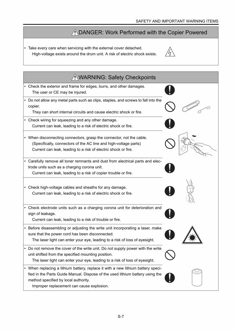
S-7
• Take every care when servicing with the external cover detached.High-voltage exists around the drum unit. A risk of electric shock exists.
WARNING: Safety Checkpoints• Check the exterior and frame for edges, burrs, and other damages.
The user or CE may be injured.
• Do not allow any metal parts such as clips, staples, and screws to fall into thecopier.
They can short internal circuits and cause electric shock or fire.
• Check wiring for squeezing and any other damage. Current can leak, leading to a risk of electric shock or fire.
• When disconnecting connectors, grasp the connector, not the cable.(Specifically, connectors of the AC line and high-voltage parts)Current can leak, leading to a risk of electric shock or fire.
• Carefully remove all toner remnants and dust from electrical parts and elec-trode units such as a charging corona unit.
Current can leak, leading to a risk of copier trouble or fire.
• Check high-voltage cables and sheaths for any damage.Current can leak, leading to a risk of electric shock or fire.
• Check electrode units such as a charging corona unit for deterioration andsign of leakage.
Current can leak, leading to a risk of trouble or fire.
• Before disassembling or adjusting the write unit incorporating a laser, makesure that the power cord has been disconnected.
The laser light can enter your eye, leading to a risk of loss of eyesight.
• Do not remove the cover of the write unit. Do not supply power with the writeunit shifted from the specified mounting position.
The laser light can enter your eye, leading to a risk of loss of eyesight.
• When replacing a lithium battery, replace it with a new lithium battery speci-fied in the Parts Guide Manual. Dispose of the used lithium battery using themethod specified by local authority.
Improper replacement can cause explosion.
DANGER: Work Performed with the Copier Powered

SAFETY AND IMPORTANT WARNING ITEMS
S-8
WARNING: Safety Checkpoints
• After replacing a part to which AC voltage is applied (e.g., optical lamp andfixing lamp), be sure to check the installation state.
A risk of fire exists.
• Check the interlock switch and actuator for loosening and check whether theinterlock functions properly.
If the interlock does not function, you may receive an electric shock or beinjured when you insert your hand in the copier (e.g., for clearing paperjam).
• Make sure the wiring cannot come into contact with sharp edges, burrs, orother pointed parts.
Current can leak, leading to a risk of electric shock or fire.
• Make sure that all screws, components, wiring, connectors, etc. that wereremoved for safety check and maintenance have been reinstalled in the orig-inal location. (Pay special attention to forgotten connectors, pinched cables,forgotten screws, etc.)
A risk of copier trouble, electric shock, and fire exists.
DANGER: HANDLING OF SERVICE MATERIALS• Toner and developer are not harmful substances, but care must be taken not
to breathe excessive amounts or let the substances come into contact witheyes, etc. It may be stimulative.
If the substances get in the eye, rinse with plenty of water immediately.When symptoms are noticeable, consult a physician.
• Never throw the used cartridge and toner into fire.You may be burned due to dust explosion.

SAFETY AND IMPORTANT WARNING ITEMS
S-9
[3] MEASURES TO TAKE IN CASE OF AN ACCIDENT1. If an accident has occurred, the distributor who has been notified first must immediately take emergency measures to
provide relief to affected persons and to prevent further damage.2. If a report of a serious accident has been received from a customer, an on-site evaluation must be carried out quickly
and KMBT must be notified.3. To determine the cause of the accident, conditions and materials must be recorded through direct on-site checks, in
accordance with instructions issued by KMBT.4. For reports and measures concerning serious accidents, follow the regulations given in “Serious Accident Report/
Follow-up Procedures”.
[4] CONCLUSION1. Safety of users and customer engineers depends highly on accurate maintenance and administration. Therefore,
safety can be maintained by the appropriate daily service work conducted by the customer engineer.2. When performing service, each copier on the site must be tested for safety. The customer engineer must verify the
safety of parts and ensure appropriate management of the equipment.
DANGER : HANDLING OF SERVICE MATERIALS
• Unplug the power cord from the wall outlet.Drum cleaner (isopropyl alcohol) and roller cleaner (acetone-based) arehighly flammable and must be handled with care. A risk of fire exists.
• Do not replace the cover or turn the copier ON before any solvent remnantson the cleaned parts have fully evaporated.
A risk of fire exists.
• Use only a small amount of cleaner at a time and take care not to spill anyliquid. If this happens, immediately wipe it off.
A risk of fire exists.
• When using any solvent, ventilate the room well.Breathing large quantities of organic solvents can lead to discomfort.

SAFETY AND IMPORTANT WARNING ITEMS
S-10
The Center for Devices and Radiological Health (CDRH) of the U.S. Food and Drug Administration implementedregulations for laser products manufactured since August 1, 1976. Compliance is mandatory for products mar-keted in the United States.
This copier is certified as a “Class 1” laser product under the U.S.Department of Health and Human Services (DHHS) Radiation Performance Standard according to the RadiationControl for Health and Safety Act of 1968. Since radiation emitted inside this copier is completely confined withinprotective housings and external covers, the laser beam cannot escape during any phase of normal user opera-tion.
SAFETY INFORMATION
IMPORTANT INFORMATION
SAFETY AND IMPORTANT WARNING ITEMS
S-11
This machine is provided with the following safety circuitsto prevent machine faults from resulting in serious acci-dents.
[1] Overall protection circuit
[2] L2 and L3 (fixing heater lamps) overheating
prevention circuit
These safety circuits are described below to provide theservice engineer with a renewed awareness of them inorder to prevent servicing errors that may impair theirfunctions.
[1] Overall Protection Circuit
1. Protection by CBR1 and CBR2 (circuit
breakers)
CBR1 and CBR2 interrupt the AC line instanta-neously when an excessive current flows due to ashort in the AC line.
CAUTION:
The CBR1 and CBR2 functions must not
be deactivated under any circumstances.
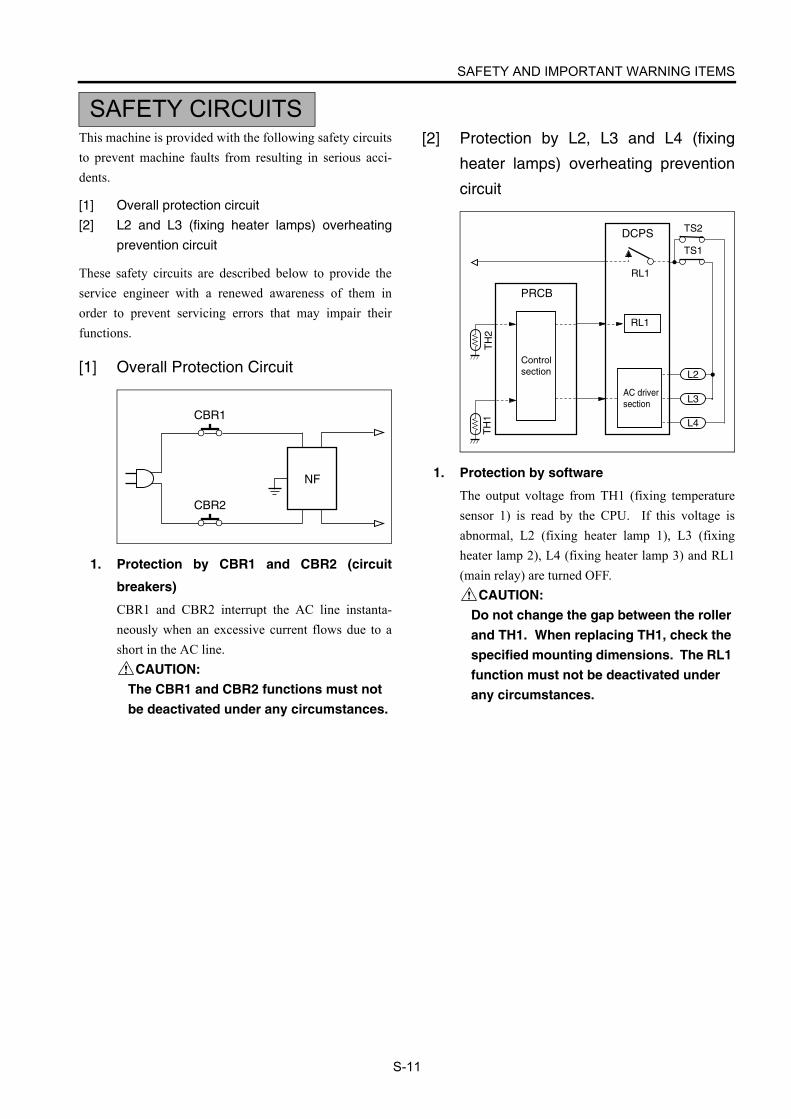
[2] Protection by L2, L3 and L4 (fixing
heater lamps) overheating prevention
circuit
1. Protection by software
The output voltage from TH1 (fixing temperaturesensor 1) is read by the CPU. If this voltage isabnormal, L2 (fixing heater lamp 1), L3 (fixingheater lamp 2), L4 (fixing heater lamp 3) and RL1(main relay) are turned OFF.
CAUTION:
Do not change the gap between the roller
and TH1. When replacing TH1, check the
specified mounting dimensions. The RL1
function must not be deactivated under
any circumstances.
SAFETY CIRCUITS
NF
CBR2
CBR1L3
L4
DCPS
PRCB
L2
Controlsection
TH
2T
H1
RL1
RL1
TS1
TS2
AC driversection

SAFETY AND IMPORTANT WARNING ITEMS
S-12
2. Protection by the hardware circuit
The output voltages from TH1 and TH2 (fixingtemperature sensors) are compared with the abnor-mality judgment reference value in the comparatorcircuit. If the output voltage from TH1 or TH2exceeds the reference value, L2 (fixing heater lamp1), L3 (fixing heater lamp 2), L4 (fixing heaterlamp 3) and RL1 (main relay) are turned OFF inhardware means.
CAUTION:
Periodically check the TH2 face contact-
ing the roller, and replace TH2 if any
abnormality is detected.
Since TH1 (fixing temperature sensor)
face does not contact the roller, check the
distance from the roller and the sensor
orientation if any abnormality is detected.
The RL1 function must not be deactivated
under any circumstances.
3. Protection by TS1 (thermostat/U) and TS2
(thermostat/L)
When the temperature of the fixing roller (upper/lower) exceeds the specified value, TSs are turnedOFF, thus interrupting the power to L2 (fixingheater lamp/1), L3 (fixing heater lamp/2), and L4(fixing heater lamp/3) directly.
CAUTION:
Do not use any other electrical conductor
in place of TS1 and TS2. Do not change
the distance between the roller and TS
(thermostat).

SAFETY AND IMPORTANT WARNING ITEMS
S-13
Caution labels shown below are attached in some areas on/in the machine.When accessing these areas for maintenance, repair, or adjustment, special care should be taken to avoid burns and electricshock.
CAUTION
INDICATION OF WARNING ON THE MACHINE
You may be burned or injured if you touch any area that you are advised by any caution label to keep your-self away from.Do not remove caution labels. If any caution label has come off or soiled and therefore the caution cannot be read, contact our Service Office.
High temperature! Do not touch. Use care when clearing paper.
ÁTemperatura alta! No tocar. Tener cuidado al remover el papel.
Alta temperatura! Non toccare. Agire con prudenza nel rimuovere la carta.
Hei§e OberflŠche!Brandverletzungsgefahr. Bei Beseitigung von Papierstaus vorsichtig vorgehen.
Temp rature lev e! Risque de br lure. Soyez prudent en retirant la feuille coinc e.
VORSICHT
CAUTION
ATTENTION
PRECAUCION
ATTENZIONE
CAUTIONATTENTIONVORSICHTPRECAUCIONATTENZIONE
ATTENTIONVORSICHTPRECAUCIONATTENZIONE
CAUTION
This area generates high voltage. If touched, electrical shock may occur. DO NOT TOUCH.
DO NOT INSERT your finger into the two RADF hinge portions; otherwise you may be injured.
CAUTION
The fixing unit is very hot. To avoide getting burned, DO NOT TOUCH.
DO NOT put your hand between the main body and developing fixing unit; otherwise you may be injured.
CAUTION
WARNING
The conveyance fixing unit is heavy. Use care and draw it out gently; otherwise you may be injured.
CAUTIONCAUTION
SAFETY AND IMPORTANT WARNING ITEMS
S-14
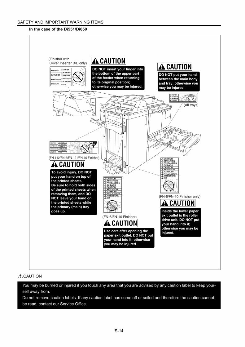
In the case of the Di551/Di650
CAUTION
You may be burned or injured if you touch any area that you are advised by any caution label to keep your-self away from.Do not remove caution labels. If any caution label has come off or soiled and therefore the caution cannot be read, contact our Service Office.
(FN-6/FN-10 Finisher)
(FN-6/FN-10 Finisher only)
(FN-112/FN-6/FN-121/FN-10 Finisher)
(Finisher with Cover Inserter B/E only)

SAFETY AND IMPORTANT WARNING ITEMS
S-15
In the case of the Di5510/Di7210
CAUTION
You may be burned or injured if you touch any area that you are advised by any caution label to keep your-self away from.Do not remove caution labels. If any caution label has come off or soiled and therefore the caution cannot be read, contact our Service Office.
7272sf006
The shift tray moves to and fro while printing. DO NOT put your hand in between the tray and tray supporting part; otherwise you may be injured.Also, DO NOT put your hand in the paper exit outlet while the tray is moving; otherwise you may be injured.
DO NOT put your hand between the main body and tray; otherwise you may be injured.
DO NOT put your hand between the main body and tray; otherwise you may be injured.
(OT-104 Shift tray)
(Main body tray 1 and 2)
(Main body tray 3 and 4)

SAFETY AND IMPORTANT WARNING ITEMS
S-16
CAUTION
You may be burned or injured if you touch any area that you are advised by any caution label to keep your-self away from.Do not remove caution labels. If any caution label has come off or soiled and therefore the caution cannot be read, contact our Service Office.
7272sf007
(FN-115 Finisher)
Use care after opening the paper exit outlet.DO NOT put your hand into it; otherwise you may be injured.
To avoid injury, DO NOT put your hand on top of the printed sheets.Be sure to hold both sides of the printed sheets when removing them, and DO NOT leave your hand on the printed sheets while the primary (main) tray goes up.

SAFETY AND IMPORTANT WARNING ITEMS
S-17
<SCANNER SECTION>
<WRITE UNIT>
In the case of the Di551/Di650
In the case of the Di5510/Di7210
7272sf004
7272sf005
7272sf001

SAFETY AND IMPORTANT WARNING ITEMS
S-18
<REAR COVER>
CAUTION
You may be burned or injured if you touch any area that you are advised by any caution label to keep your-self away from.Do not remove caution labels. If any caution label has come off or soiled and therefore the caution cannot be read, contact our Service Office.

SAFETY AND IMPORTANT WARNING ITEMS
S-19
CAUTION
You may be burned or injured if you touch any area that you are advised by any caution label to keep your-
self away from.
Do not remove caution labels. If any caution label has come off or soiled and therefore the caution cannot
be read, contact our Service Office.
<ZK Puncher with Z-folding>
WARNING

Blank page
Di551/Di650/Di5510/Di7210 LIST OF DIFFERENCE
1
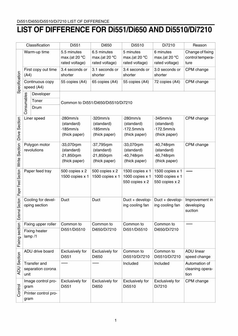
LIST OF DIFFERENCE FOR Di551/Di650 AND Di5510/Di7210
Classification Di551 Di650 Di5510 Di7210 Reason
Spe
cific
atio
n
Warm-up time 5.5 minutes max.(at 20 ºC rated voltage)
6.5 minutes max.(at 20 ºC rated voltage)
5 minutes max.(at 20 ºC rated voltage)
6 minutes max.(at 20 ºC rated voltage)
Change of fixing control tempera-ture
First copy out time (A4)
3.4 seconds or shorter
3.1 seconds or shorter
3.4 seconds or shorter
3.0 seconds or shorter
CPM change
Continuous copy speed (A4)
55 copies (A4) 65 copies (A4) 55 copies (A4) 72 copies (A4) CPM change
Con
sum
able
s Developer
Common to Di551/Di650/Di5510/Di7210Toner
Drum
Driv
e S
ectio
n Liner speed ·280mm/s (standard)·185mm/s (thick paper)
·320mm/s (standard)·185mm/s (thick paper)
·280mm/s (standard)·172.5mm/s (thick paper)
·345mm/s (standard)·172.5mm/s (thick paper)
CPM change
Writ
e S
ectio
n Polygon motor revolutions
·33,070rpm (standard)·21,850rpm (thick paper)
·37,795rpm (standard)·21,850rpm (thick paper)
·33,070rpm (standard)·40,748rpm (thick paper)
·40,748rpm (standard)·40,748rpm (thick paper)
CPM change
Pape
r Fee
d Se
ctio
n Paper feed tray 500 copies x 21500 copies x 1
500 copies x 21500 copies x 1
1500 copies x 11000 copies x 1550 copies x 2
1500 copies x 11000 copies x 1550 copies x 2
Exte
rnal
Sect
ion Cooling for devel-
oping sectionDuct Duct Duct + develop-
ing cooling fanDuct + develop-ing cooling fan
Improvement in developing suction
Fix
ing
sect
ion Fixing upper roller Common to
Di551/Di5510Common to Di650/Di7210
Common to Di551/Di5510
Common to Di650/Di7210Fixing heater
lamp /1
AD
U S
ectio
n ADU drive board Exclusively for Di551
Exclusively for Di650
Common to Di5510/Di7210
Common to Di5510/Di7210
ADU linear speed change
Transfer and separation corona unit
Included Included Automation of cleaning opera-tion
Con
trol
Image control pro-gram
Exclusively for Di551
Exclusively for Di650
Exclusively for Di5510
Exclusively for Di7210
CPM change
Printer control pro-gram

Blank page

1
1 O
UT
LIN
E
OUTLINE

1 O
UT
LIN
E
Blank page

MAIN BODY
1-1
1 O
UT
LIN
E
OUTLINE OF SYSTEM
In the case of the Di551/Di650
7165ma1001
A4LCT[C-403]
A3LCT[C-404]
Expansion memory
Hard disk
Finisher[FN-112]
Finisher[FN-6]
Finisher[FN-113]
Cover Inserter[Cover Inserter B]
Punch kit[PK-2/5]
Punch kit[PK-2/5]
Punch with
Z-folding function[ZK-2]Adapter for ZK
[ZK A kit]
Adapter for ZK[ZK A kit]
Key counter
Paper exit tray
Cover Inserter[Cover Inserter B]

MAIN BODY
1-2
1 O
UT
LIN
E
In the case of the Di5510/Di7210
7272ma1001
Adapter for ZK[ZK A-kit]
Adapter for ZK[ZK A-kit]
Shift tray[OT-104]
A4LCT[C-403]
A3LCT[C-404]
Expansion memory
Hard disk
Finisher[FN-121]
Finisher[FN-10]
Finisher[FN-115]
Cover Inserter[Cover Inserter E]
Cover Inserter[Cover Inserter E]
Punch kit[PK-2/5]
Punch kit[PK-2/5]
Key counter
Paper exit tray
Punch withZ-folding function
[ZK-2/3]
Finisher[FN-122] *Di5510 only

MAIN BODY
1-3
1 O
UT
LIN
E
Di551/Di650/Di5510/Di7210 PRODUCT SPECIFICATIONS
[1] TypeInstallation type:
Console type (floor-mounted)Copying method:
Indirect electrostatic methodDocument tray type:
FixedPhotosensitive material:
OPCSensitizing method:
Laser writingPaper feed trays:
Di551/Di650:Three stacked trays (two for 500 sheets of 80
g/m2 or 20lbs paper, 1500 sheets of 80 g/m2 or20lbs paper)Di5510/Di7210:
Four stacked trays (1500 sheets: 64g/m2 x 1,
1000 sheets: 64g/m2 x 1, 550 sheets: 64g/m2
x 2)Common:By-pass tray for various paper sizes (100
sheets of 80 g/m2 or 20lbs paper)
C-403 (4000 sheets of 80 g/m2 or 20lbspaper)*1,
C-404 (4000 sheets of 80/m2 or 20lbs paper)*1*1: Optional
[2] FunctionsApplicable document types:
Sheets, book, solid objectDocument size:
A3/11x17 max.Copy paper size:• Metric area
A3 to A6R, 11x17 to 8.5x11, F4• Inch area
11x17 to 8.5x5.5, A3 to B5R, F4Wide paper (Di551/Di650:314 mm x 459 mm max.)(Di5510/Di7210:314 mm x 458 mm max.)
MagnificationsFixed magnifications:• Metric area
x1.00, x2.00, x1.41, x1.22, x1.15, x0.86, 0.82,x0.71, x0.50
• Inch areax1.00, x2.00, x1.55, x1.29, x1.21, x0.93, 0.77,x0.65, x0.50
Special ratio magnifications:3 modes
Zoom magnifications:x0.25 to x4.00 (in 1% steps)
Vertical magnifications:x0.25 to x4.00 (in 1% steps)
Horizontal magnifications:x0.25 to x4.00 (in 1% steps)
Warm-up time:
First copy out time (FCOT)
*Straight paper ejection, platen mode, life size,non AE or AES, without finisher, paper feedfrom tray 1
Continuous copy speed (life size, copies/min)
Continuous copy count:1 to 9999
Copy density selection:AE or AES, manual (9 steps)Arbitrary density (2 modes)
E-RDH memory capacity:Standard 64 MBMaximum 320 MB (Di551/Di650), 576 MB (Di5510/Di7210)
Di551 5.5 minutes max. 20 °C, rated voltageDi650 6.5 minutes max.
Di5510 5 minutes max.
Di7210 6 minutes max.
Mode A4/8.5x11
Manual 3.4 seconds or shorter (Di551)
3.1 seconds or shorter (Di650)
3.4 seconds or shorter (Di5510)
3.0 seconds or shorter (Di7210)
Size cpm
A4/8.5x11 55 (Di551)
65 (Di650)
55 (Di5510)
72 (Di7210)

MAIN BODY
1-4
1 O
UT
LIN
E
[3] Applicable Copy PaperPlain paper:
High-quality paper of 60 g/m2 or 17lbs to 90 g/
m2 or 24lbsSpecial paper (by-pass feed only):
OHP filmBlueprint master paper(both by-pass tray and stacked trays):Tabs
Plain paper of 50 g/m2 or 13lbs to 59 g/m2 or16lbs
Plain paper of 91 g/m2 or 24lbs to 200 g/m2 or45lbs
[4] OptionsLCT: C-403, C-404Key counterExpansion memory unit:
64MB, 128MB256MB*1
Paper exit trayHard disk: HDD-2Finisher: FN-112, FN-6, FN-121, FN-10,
FN-115, FN-113, FN-122Shift tray: OT-104Cover Inserter: Cover Inserter B/EPuncher: PK-2, PK-5Puncher with Z-folding: ZK-2, ZK-3*1 256MB use the recommend memory
[5] Particulars of MachinePower supply:
230 VAC -14% to 10.6% 50Hz/60Hz120 VAC ±10% 60 Hz
Power consumption:230 V Machine : 2300 W max. (full option)120 V Machine : 1920 W max. (full option)
Weight: Approx. 203 kg (Di551/Di650)Approx. 216 kg (Di5510/Di7210)
External dimensions:
For Di5510/Di7210 models, the shapes of thetray are different.
[6] Maintenance and LifePeriodic maintenance: Every 250,000 copiesMachine life: 5,000,000 copies or 5 years
[7] ConsumablesDeveloper: Common to Di551/Di650/Di5510/
Di7210Toner: Common to Di551/Di650/Di5510/
Di7210Drum: Common to Di551/Di650/Di5510/
Di7210 (φ80)
[8] Environmental ConditionsTemperature: 10°C to 30°C (50°F to 86°F)Humidity: 10% to 80% RH
Note: The information herein may be subject tochange for improvement without notice.
(mm)
766650
1140

MAIN BODY
1-5
1 O
UT
LIN
E
CENTRAL CROSS-SECTIONAL VIEW
In the case of the Di551/Di650
Charging corona section
Image write section
Cleaning section
PCL
TSL
Toner supply section
Fixing section Developing section
Image read section
RADF(EDH-4)
Second paper feed section Paper exit section Bypass tray
Paper reverse exit section Loop roller
Transfer corona section
Tray 1
Tray 2
Tray 3
Vertical conveyance section
ADU
Paper conveyance section
Separation corona section
MAIN BODY
1-6
1 O
UT
LIN
E
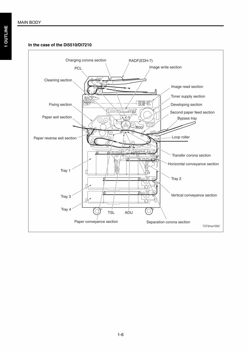
In the case of the Di5510/Di7210
7272ma1002
Charging corona section
Image write section
Cleaning section
PCL
TSL
Toner supply section
Fixing section Developing section
Image read section
RADF(EDH-7)
Second paper feed section Paper exit section Bypass tray
Paper reverse exit section Loop roller
Transfer corona section
Tray 1
Tray 3
Tray 2
Tray 4
Vertical conveyance section
ADU
Paper conveyance section Separation corona section
Horizontal conveyance section
MAIN BODY
1-7
1 O
UT
LIN
E
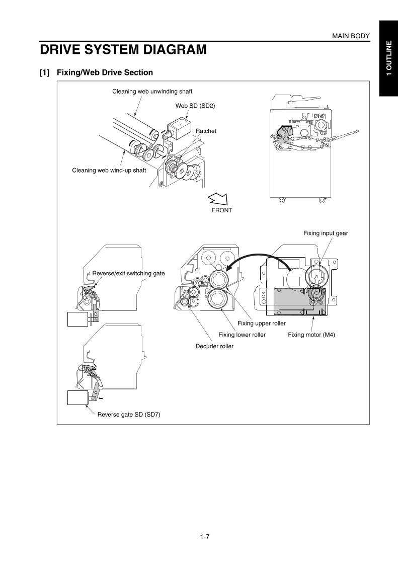
DRIVE SYSTEM DIAGRAM
[1] Fixing/Web Drive Section
FRONT
Cleaning web unwinding shaft
Web SD (SD2)
Ratchet
Cleaning web wind-up shaft
Reverse/exit switching gate
Fixing upper roller
Fixing lower roller
Decurler roller
Fixing input gear
Fixing motor (M4)
Reverse gate SD (SD7)

MAIN BODY
1-8
1 O
UT
LIN
E
[2] Drum Drive Section
[3] Developing Drive Section
Separation claw SD(SD1)
Separation claw swing cam
Separation claw sectionDrum motor (M2)
Drum
Toner conveyance screwToner guide roller
Drum motor (M2)Toner conveyance screw
Developing motor (M3)
Developing sleeve
Agitator wheel
Agitator screws

MAIN BODY
1-9
1 O
UT
LIN
E
[4] Paper Feed/Vertical Conveyance/Tray Up Drive SectionsIn the case of the Di551/Di650
Feed roller
Paper feed MC (MC3/5/7)Paper feed roller
Pre-registration MC (MC4/6/8)
Pre-registration roller
Double feed prevention rollerTray 1/2
Drive belt
Vertical conveyance MC/1 (MC11)
Vertical conveyance roller (upper)
Vertical conveyance MC/2 (MC12)
Vertical conveyance roller (middle)
Paper feed motor (M1)
Up/down plate
Tray up drive motor/1 (M16)
Tray up drive motor/2 (M17)
Tray up drive motor/3 (M18)

MAIN BODY
1-10
1 O
UT
LIN
E
In the case of the Di5510/Di7210
7272ma1003
Feed roller
Paper feed rollerPre-registration MC (MC4/6/8/10)
Pre-registration roller
Double feed prevention rollerTray 1/2/3/4
Drive belt
Drive belt
Vertical conveyance MC/1 (MC11)
Horizontal conveyance roller/R
Horizontal conveyance MC/R (MC16)
Horizontal conveyance MC/L (MC15)
Vertical conveyance roller (upper)
Vertical conveyance MC/2 (MC12)
Vertical conveyance roller (middle)
Paper feed motor (M1)
Up/down plate
Tray up drive motor/1 (M16)
Tray up drive motor/2 (M17)
Tray up drive motor/3 (M18)
Tray up drive motor/4 (M19)
Paper feed MC(MC3/5/7/9)
Horizontal conveyance roller/L
Vertical conveyance roller (lower)

MAIN BODY
1-11
1 O
UT
LIN
E
[5] By-pass Paper Feed /ADU Pre-registration Drive Section
Paper feed roller
Feed roller
Loop roller
Loop roller motor (M6)ADU pre-registration roller
Up/down motor/BP (M20)
Paper up/downplate

MAIN BODY
1-12
1 O
UT
LIN
E
[6] Charging and Transfer/Separation Wire Cleaning Drive Section
FRONT
[Charging corona unit]
[Transfer and separation corona unit]
Charging cleaning motor (M14)
Transfer/separation cleaning motor (M10)
MAIN BODY
1-13
1 O
UT
LIN
E
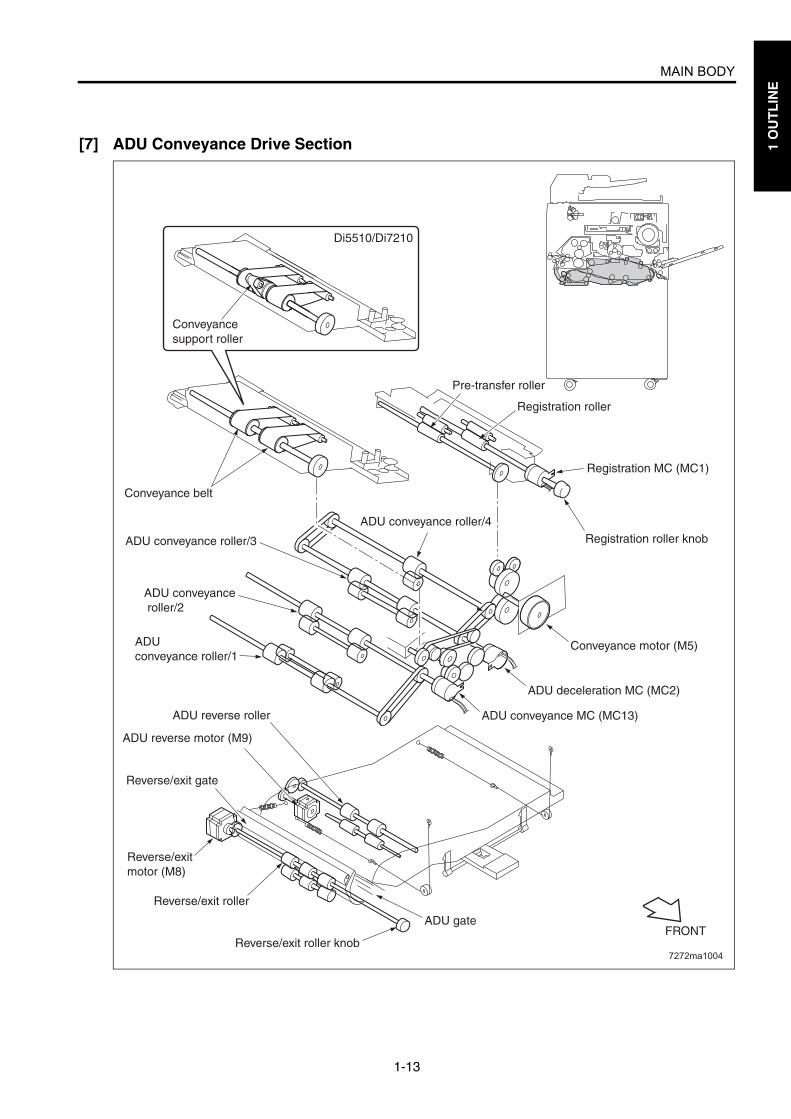
[7] ADU Conveyance Drive Section
7272ma1004
Pre-transfer roller
Registration roller
Conveyance belt
ADU conveyance roller/3
ADU conveyance roller/4
ADU conveyance roller/2
ADU conveyance roller/1
Conveyance motor (M5)
ADU deceleration MC (MC2)
ADU conveyance MC (MC13)
ADU gate
ADU reverse motor (M9)
Reverse/exit gate
Reverse/exit motor (M8)
Reverse/exit roller
Reverse/exit roller knob
ADU reverse roller
FRONT
Registration MC (MC1)
Registration roller knob
Di5510/Di7210
Conveyance support roller

MAIN BODY
1-14
1 O
UT
LIN
E
[8] Paper Exit Drive Section
[9] Toner Supply Drive Section
Paper exit motor (M7)
Paper exit roller Exit conveyance roller
Toner cartridge
Toner bottle motor (M13)
Toner supply screws
Toner supply motor (M12)
Toner supply screw
Toner conveyance screw
[Rear view]
[Front view]
MAIN BODY
1-15
1 O
UT
LIN
E
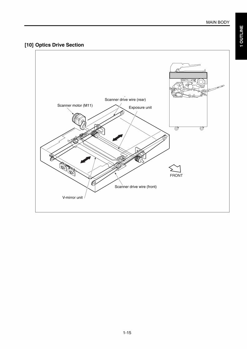
[10] Optics Drive Section
FRONT
Scanner motor (M11)
Scanner drive wire (rear)
Exposure unit
Scanner drive wire (front)
V-mirror unit

1 O
UT
LIN
E
Blank page
2 2 U
NIT
EX
PL
AN
AT
ION
UNIT EXPLANATION

2 U
NIT
EX
PL
AN
AT
ION
Blank page

EXTERNAL SECTION
2-A-1
2 U
NIT
EX
PL
AN
AT
ION
EXTERNAL SECTION
[1] CompositionIn the case of the Di551/Di650
Operation panel
Sub power switch (SW2)
Toner supply cover
Front right cover
Front left cover
Tray 1
Tray 2
Tray 3
Right side cover (upper)
Developing suction filter cover
Bypass tray
Right side cover (lower rear)
Vertical conveyance door
Right side cover (lower middle)
Right side cover (lower front)
Left side cover
Main power switch (SW1)
Ozone filter cover
Optional coverPaper exit tray
Rear cover
RADF

EXTERNAL SECTION
2-A-2
2 U
NIT
EX
PL
AN
AT
ION
In the case of the Di5510/Di7210
7272ma2001
Rear cover
Optional cover
Ozone filter cover
Main power switch (SW1)
Left side cover
Paper exit tray
Tray 1
RADF
Right side cover (upper)
Operation panel
Developing suction filter cover
Bypass tray
Right side cover (lower rear)
Vertical conveyance door
Right side cover (lower middle)
Right side cover (lower front)
Tray 2
Horizontal conveyance section
Tray 3
Tray 4
Front right cover
Front left cover
Toner supply cover
Sub power switch (SW2)

DRIVE SECTION
2-B-1
2 U
NIT
EX
PL
AN
AT
ION
DRIVE SECTION
[1] Composition
[2] Mechanisms *1 Independent drive mechanismsDrive mechanisms of this machine are driven bydedicated motors to ensure high-speed opera-tion and to improve serviceability of the drum unitand developing performance.Speeds of the drum motor (M2), fixing motor(M4), and loop roller motor (M6) are switched asshown below according to the paper typeselected in the key operator mode, thus enhanc-
ing reliability of copying on thick paper.
7272ma2002
Scanner motor (M11)
Toner bottle motor (M13)
Drum motor (M2)
Loop roller motor (M6)
Developing motor (M3)
Fixing motor (M4)
Paper feed motor (M1)
Mecha-nism
Driven Parts Method
Drum drive*1
Drum, Toner guide roller, Toner con-veyance screw, and Separation claw swing
Gear drive (ded-icated motor)
Develop-ing drive*1
Developing sleeve Gear drive (ded-icated motor)
Fixing drive*1
Fixing roller (upper) Gear drive (ded-icated motor)
Paper feed drive*1
Tray 1/2/3, Vertical conveyance roller (middle/lower)
Gear drive (ded-icated motor) + Belt
By-pass/loop drive*1
By-pass feed roller and ADU pre-regis-tration roller
Gear drive (ded-icated motor) + Belt
Scanner drive*1
Exposure unit, V-mirror unit
Wire drive (dedi-cated motor )+ Belt
Paper exit drive*1
Paper exit roller Gear drive (ded-icated motor)
Paper type Motor speed
Thick paper 185 mm/s (Di551/Di650)
172.5mm/s (Di5510/Di7210)
Others 280 mm/s (Di551/Di5510)
320 mm/s (Di650)
345 mm/s (Di7210)

DRIVE SECTION
2-B-2
2 U
NIT
EX
PL
AN
AT
ION
[3] M2 (Drum) Control
M2 (drum) is controlled by PRCB (printer controlboard) and the motor drive power is suppliedfrom DCPS (DC power supply unit).
1. OperationM2 (drum) is a motor driven by 24 VDC. It drivesthe drum, toner guide roller, toner conveyancescrew, and separation claw swing. The flywheelmechanism adopted for M2 ensures accurateand steady rotation.M2 starts rotating when the START button ispressed and stops when the specified timelapses after completion of second paper feedingof the last copy.When either one of the front-left and front-rightdoors of this machine opens, MS1 (interlock MS/R) or MS2 (interlock MS/L) actuates to stop sup-plying the DC power to the motor, causing M2 tostop.
2. Signalsa. Input signal(1) DRUM_EM (M2 to PRCB)
M2 (drum) rotation abnormality detection signal[H]: Rotation error (when motor speed changes
by 6.5% more or less than the motor speedspecified value)
[L]: Normal rotationb. Output signals(1) DRUM_CONT (PRCB to M2)
M2 (drum) ON/OFF control signal[L]: M2 ON[H]: M2 OFF
(2) CW/CCW (PRCB to M4)M2 (drum) rotational direction switchover signal[L]: CW rotation[H]: CCW rotation
(3) DRUM_CLK (PRCB to M2)M2 (drum) rotational speed control clock signal
PRCB
DCPS
24V2
P.GND
MS1 MS2
M2
5VP.GND
DRUM CONTDRUM CLK
CW/CCWDRUM EM

DRIVE SECTION
2-B-3
2 U
NIT
EX
PL
AN
AT
ION
[4] M4 (Fixing) Control
M4 (fixing) is controlled by PRCB (printer controlboard) and the motor drive power is suppliedfrom DCPS (DC power supply unit).
1. OperationM4 (fixing) is a motor driven by 24 VDC. It drivesthe fixing roller. M4 starts rotating when the START button ispressed and stops when the last copied paperhas been ejected.During the warm-up operation, M4 rotates torotate the fixing roller.
2. Signalsa. Input signal(1) MAINM_EM (M4 to PRCB)
M4 (fixing) rotation error detection signal[H]: Rotation error (when motor speed changes
by 6.5% more or less than the motor speedspecified value)
[L]: Normal rotationb. Output signals(1) MAINM_CONT (PRCB to M4)
M4 (fixing) ON/OFF control signal[L]: M4 ON[H]: M4 OFF
(2) MAINM_F/R (PRCB to M4)M4 (fixing) rotational direction switchover signal[L]:CW rotation[H]:CCW rotation
(3) MAINM_EM (M4 to PRCB)M4 (fixing) rotational speed control clock signal
PRCB
DCPS
24V2
P.GND
MS1 MS2
M4
5VP.GND
MAINM CONTMAINM CLKMAINM F/RMAINM EM

2 U
NIT
EX
PL
AN
AT
ION
Blank page

SCANNER SECTION
2-C-1
2 U
NIT
EX
PL
AN
AT
ION
SCANNER SECTION
[1] Composition
[2] Mechanisms
Scanner HP PS (PS61)
Exposure unit
APS sensor 3 (PS65)V-mirror unit
APS sensor 1 (PS63)
APS sensor 2 (PS64)
Optical rail (R)
Scanner cooling fan (FM9)
Scanner drive wire
Exposure lamp (L1)
L1 inverter (L1 INVB) A/D converter board (ADB)
Slit glass
CCD unit
Mechanism Method
Light source Xenon lamp
Exposure Light source moving slit exposure, static exposure
Scanning Platen original scanning: 1st, 2nd, and 3rd mirrors are shifted.RADF original scanning: Original is moved with light source held sta-tionary.
Lamp power supply
Lamp cord
Scanner cooling
Cooling fan

SCANNER SECTION
2-C-2
2 U
NIT
EX
PL
AN
AT
ION
[3] M11 (Scanner) Control
M11 (scanner) is driven by SCDB (scanner driveboard) and is controlled by PRCB (printer controlboard).The related signal is PS61 (scanner HP).
1. Operationa. Operation of M11 (scanner)
M11 (scanner) is a 3-phase stepping motordriven by the 3-phase bipolar constant-currentdrive method. The motor is turned ON/OFF bysupplying/stopping clock pulses.The rotational speed, direction, and amount ofmovement of M11 is determined by the incre-ment of the driving step count. This count is reseteach time PS61 (scanner HP) is turned ON orOFF by the exposure unit.
b. Movement speed of the exposure unitScanning speed
c. Exposure unit home position searchWhen SW2 (sub power switch) or the STARTbutton is pressed, M11 (scanner) searches forthe home position of the exposure unit. How-ever, this operation is performed in differentways depending on whether PS61 (scanner HP)is ON or OFF.
(1) When PS61 (scanner HP) is OFF
(2) When PS61 (scanner HP) is ON
d. Read with shading correctionShading correction is performed in differentways depending on whether SW2 (sub power) isON or the START button is ON. When shadingcorrection starts, the exposure unit is at thehome position and PS61 (scanner HP) is OFF.
(1) When SW2 (sub power) is ONL1 (exposure lamp) turns ON. Next, M11 (scan-ner) moves the exposure unit toward the paperexit side. After being driven by the specified num-ber of steps, M11 stops, thus reading the lightreflected by the white reference plate installedunderneath the glass stopper plate and perform-ing the first white correction. Next, M11 movesthe exposure unit toward the paper exit side.After being driven by the specified number ofsteps, M11 performs the second white correc-tion.Then, L1 is turned OFF for black correction,searching for the home position of the exposureunit.In each of the first and second shading correctionprocesses, the CCD 1 line data is read to com-pare brightness levels between pixels. Thebrighter data is used as white correction data.
Operation mode Movement speed
Scan (1:1) 320 mm/s (Di551/Di650)
357 mm/s (Di5510/Di7210)
Return 640 mm/s
Home position search 247 mm/s
PS61
SCDB
S.GNDSIG5V
M11UVW
PRCB
SCAN CLKSCAN FR
SCAN MGNSCAN CUR1SCAN CUR2SCAN CUR3
MODE1MODE2MODE3
SCANHP PS
DCPS
24V15V2
S.GNDP.GND
5V2S.GND
PS61 Platen APS read position
PS61 Platen APS read position

SCANNER SECTION
2-C-3
2 U
NIT
EX
PL
AN
AT
ION
(2) When the START button is ONL1 (exposure lamp) turns ON. Next, M11 (scan-ner) moves the exposure unit toward the paperexit side. After being driven by the specified num-ber of steps, M11 (scanner) stops, thus readingthe light reflected by the white reference plateinstalled underneath the glass stopper plate andperforming the first white correction. Next, M11moves the exposure unit toward the paper exitside. After being driven by the specified numberof steps, M11 performs the second white correc-tion. Then, M11 proceeds to the ADF copy operationor platen copy operation.
e. ADF copy operationAfter completion of the shading correctionstarted by pressing the START button, M11(scanner) moves the exposure unit toward thepaper exit side. After being driven by the speci-fied number of steps from the position wherePS61 (scanner HP) was turned ON, it stops. Thisposition is the exposure position for ADF copyoperation.Then, ADF copy operation is performed. Aftercompletion of the ADF copy operation, L1 (expo-sure lamp) is turned OFF to start searching forthe exposure unit home position.
PS61
Black correction
Home position search
First white correction
Second white correction
Platen APS read position
PS61
Home position search
First white correction
Second white correction
Platen APS read position
Original read position
SCANNER SECTION
2-C-4
2 U
NIT
EX
PL
AN
AT
ION
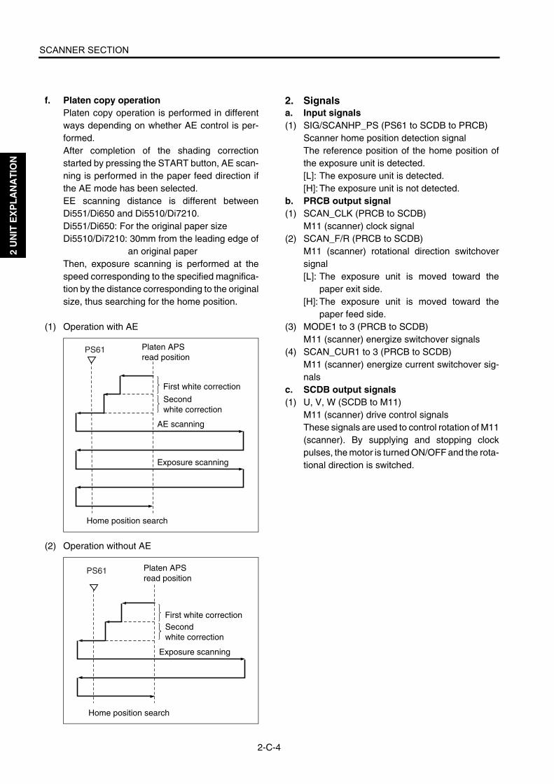
f. Platen copy operationPlaten copy operation is performed in differentways depending on whether AE control is per-formed.After completion of the shading correctionstarted by pressing the START button, AE scan-ning is performed in the paper feed direction ifthe AE mode has been selected.EE scanning distance is different betweenDi551/Di650 and Di5510/Di7210.Di551/Di650: For the original paper sizeDi5510/Di7210: 30mm from the leading edge of
an original paperThen, exposure scanning is performed at thespeed corresponding to the specified magnifica-tion by the distance corresponding to the originalsize, thus searching for the home position.
(1) Operation with AE
(2) Operation without AE
2. Signalsa. Input signals(1) SIG/SCANHP_PS (PS61 to SCDB to PRCB)
Scanner home position detection signalThe reference position of the home position ofthe exposure unit is detected.[L]: The exposure unit is detected.[H]: The exposure unit is not detected.
b. PRCB output signal(1) SCAN_CLK (PRCB to SCDB)
M11 (scanner) clock signal(2) SCAN_F/R (PRCB to SCDB)
M11 (scanner) rotational direction switchoversignal[L]: The exposure unit is moved toward the
paper exit side.[H]: The exposure unit is moved toward the
paper feed side.(3) MODE1 to 3 (PRCB to SCDB)
M11 (scanner) energize switchover signals(4) SCAN_CUR1 to 3 (PRCB to SCDB)
M11 (scanner) energize current switchover sig-nals
c. SCDB output signals(1) U, V, W (SCDB to M11)
M11 (scanner) drive control signalsThese signals are used to control rotation of M11(scanner). By supplying and stopping clockpulses, the motor is turned ON/OFF and the rota-tional direction is switched.
PS61
Home position search
First white correction
Second white correction
Platen APS read position
AE scanning
Exposure scanning
PS61
Home position search
First white correctionSecond white correction
Platen APS read position
Exposure scanning
SCANNER SECTION
2-C-5
2 U
NIT
EX
PL
AN
AT
ION
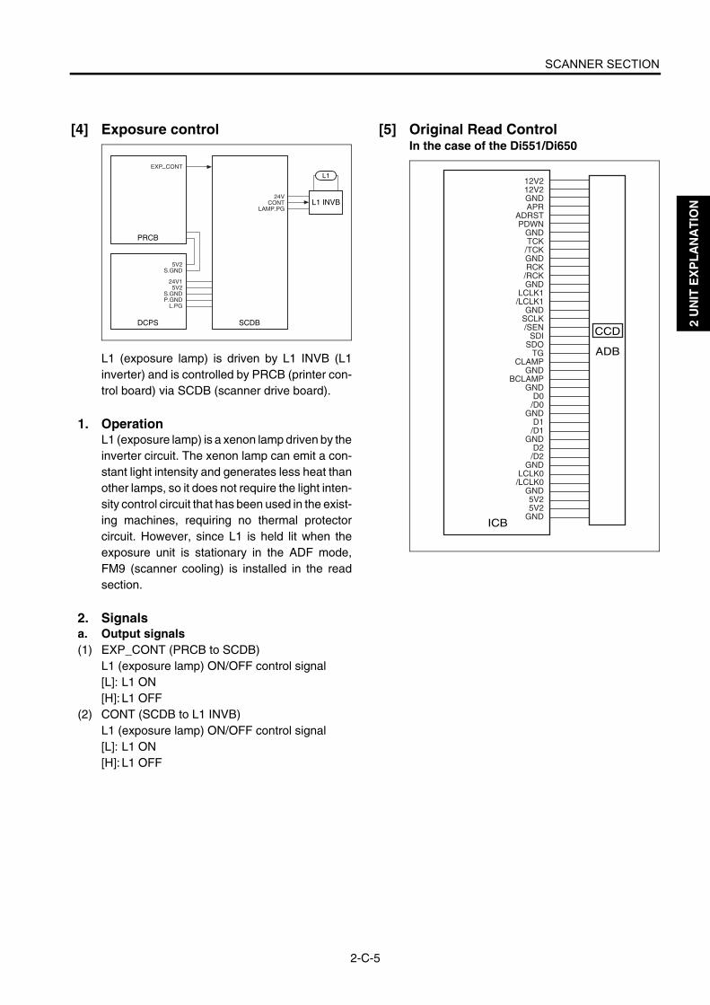
[4] Exposure control
L1 (exposure lamp) is driven by L1 INVB (L1inverter) and is controlled by PRCB (printer con-trol board) via SCDB (scanner drive board).
1. OperationL1 (exposure lamp) is a xenon lamp driven by theinverter circuit. The xenon lamp can emit a con-stant light intensity and generates less heat thanother lamps, so it does not require the light inten-sity control circuit that has been used in the exist-ing machines, requiring no thermal protectorcircuit. However, since L1 is held lit when theexposure unit is stationary in the ADF mode,FM9 (scanner cooling) is installed in the readsection.
2. Signalsa. Output signals(1) EXP_CONT (PRCB to SCDB)
L1 (exposure lamp) ON/OFF control signal[L]: L1 ON[H]: L1 OFF
(2) CONT (SCDB to L1 INVB)L1 (exposure lamp) ON/OFF control signal[L]: L1 ON[H]: L1 OFF
[5] Original Read ControlIn the case of the Di551/Di650
L1 INVB
SCDB
24VCONT
LAMP.PG
L1
PRCB
EXP CONT
DCPS
24V15V2
S.GNDP.GND
L.PG
5V2S.GND
ICB
ADB
CCD
12V212V2GNDAPR
ADRSTPDWN
GNDTCK/TCKGNDRCK/RCKGND
LCLK1/LCLK1
GNDSCLK/SEN
SDISDO
TGCLAMP
GNDBCLAMP
GNDD0/D0
GNDD1/D1
GNDD2/D2
GNDLCLK0/LCLK0
GND5V25V2
GND

SCANNER SECTION
2-C-6
2 U
NIT
EX
PL
AN
AT
ION
In the case of the Di5510/Di7210
Original read control is performed by ADB (A/Dconverter board) and CCD sensor installed inADB.
1. OperationThe light reflected by the exposed original isinput to the CCD sensor through the lens. Theanalog voltage corresponding to the quantity ofthe input light is A/D-converted in the ADB (A/Dconverter board), being output to the ICB (imagecontrol board).
a. Original readThe original read timing is as follows:
(1) Platen modeAfter lapse of the specified interval since theexposure unit turned PS61 (scanner HP) OFF.
(2) ADF modeAfter lapse of the specified interval since the orig-inal's leading edge turned PS306 (original con-veyance) ON.
ICB
ADB
CCD
GNDTG
TG_OUTCLAMP
A_CLAMPPRD_KEEP
GND+LCLK-LCLK
GND-RCLK+RCLK
GNDGND
+TCK-TCKGNDGND
SCLK/SEN
SDISDOGND
-AD_D0+AD_D0
GND-AD_D1+AD_D1
GND-AD_D2+AD_D2
GND-LVDSCLKO+LVDSCLKO
GNDADRST
APRLVDS_PDWN
GND+5V+5V+5V+5V+5V+5V
GND+12V+12V+12VGND
7272ma2017

SCANNER SECTION
2-C-7
2 U
NIT
EX
PL
AN
AT
ION
[6] APS Control
The APS method used in the platen mode is dif-ferent from that used in the ADF mode. The sig-nal read by the APS sensor or RADF's originalsize detection sensor is processed by ICB(image control board) via SCDB (scanner driveboard).
1. Operationa. APS detection (1) ADF mode
The paper size is detected according to the com-bination of ON/OFF states of PS309 (originalsize/2) and PS310 (original size/1) of the RADF'soriginal feed tray and the resistance value ofVR301 (original paper size).
(2) Platen modeThe paper size is detected according to the com-bination of ON/OFF states of PS63 (APS/1),PS64 (APS/2), and PS65 (APS/3) and the signalread by the CCD sensor. PS63 to PS65 are usedto detect the original size in the sub-scanningdirection and the CCD sensor is used to detectthe original size in the main scanning direction.
Relationships between sensors and paper sizesare as follows:
ON OFF
b. APS detection timingThe APS detection timing differs between theplaten mode and DF mode.
(1) ADF modeWhen the RADF mode is selected or an originalis set on the RADF original feed tray, APS detec-tion takes place using PS309 (original size/2),PS310 (original size/1), and VR301 (originalsize).
(2) Platen modeWhen the RADF is closed and PS51 (APS tim-ing) turns ON, L1 (exposure lamp) turns ON andthe CCD detects the reflected light to detect theoriginal size in the main scanning direction.Since RADF is still open at this time, the blacklevel of the sky shot (outside the original) and thewhite level of the original (inside the original) aredetected according to whether an original ispresent. At this time, the original size in the sub-scanning direction is detected using PS63 toPS65 (APS/1 to APS/3). When the RADF isclosed completely and PS311 (ADF open/close)turns ON, CCD reads the white level of the platencover and the black level in the original. Amongthe two original sizes detected as discussedabove, the larger size is determined as the orig-inal size in the main scanning direction.
PS51
SCDB
S.GNDAPS TIM
5V
PS63S.GNDAPS.1
APS 5V
PS64S.GNDAPS.2
APS 5V
PS65S.GNDAPS.3
APS 5V
ICB
APC CONTCOVER SIG
APS.1 SIGAPS.2 SIGAPS.3 SIG
S.GNDSIZE PS L
5VPS309
PS310
VR301
PRCB
SIZE PS LAPS TIMING
DCPS
24V15V2
S.GNDP.GND
SIZE PS SSIZE ANA
S.GNDSIZE PS S
5V
A.GNDSIZE ANA
3.3V
LED
PS65PS63 PS64
Paper exit side
Photo sensor
Sensor
Paper sizePS65 PS63 PS64
Min. size
B5R
B5
B4
A4R
A4
A3
8.5 x 11R
8.5 x 11
8.5 x 14
11x 17

SCANNER SECTION
2-C-8
2 U
NIT
EX
PL
AN
AT
ION
2. Signalsa. Input signals(1) APS_TIM (PS51 to SCDB)
ADF open/close detection signal[L]: ADF is closed.[H]: ADF is open.
(2) APS.1/APS.1_SIG (PS63 to SCDB to ICB)Paper size detection signal[L]: Paper is detected.[H]: Paper is not detected.
(3) APS.2/APS.2_SIG (PS64 to SCDB to ICB)Paper size detection signal[L]: Paper is detected.[H]: Paper is not detected.
(4) APS3/APS.3_SIG (PS65 to SCDB to ICB)Paper size detection signal[L]: Paper is detected.[H]: Paper is not detected.
(5) SIZE_PS_L (PS309 to SCDB to ICB)Paper size detection signal[L]: Paper is detected.[H]: Paper is not detected.
(6) SIZE_PS_S (PS310 to SCDB to ICB)Paper size detection signal[L]: Paper is detected.[H]: Paper is not detected.
(7) SIZE_ANA (PS301 to SCDB to ICB)Paper size detection signal[L]: Paper is detected.[H]: Paper is not detected.
(8) COVER_SIG (SCDB to ICB)Same as APS TIM signal.
(9) APS_TIMING (SCDB to PRCB)Same as APS TIM signal.
b. Output signals(1) APS_CONT
This signal controls ON/OFF states of APS_5Vpower for driving PS63, PS64, and PS65 (APS1to APS3).[L]: APS_5V OFF[H]: APS_5V ON
[7] AE ControlIn the case of the Di551/Di650
ICB
ADB
CCD
12V212V2GNDAPR
ADRSTPDWN
GNDTCK/TCKGNDRCK/RCKGND
LCLK1/LCLK1
GNDSCLK/SEN
SDISDO
TGCLAMP
GNDBCLAMP
GNDD0/D0
GNDD1/D1
GNDD2/D2
GNDLCLK0/LCLK0
GND5V25V2
GND
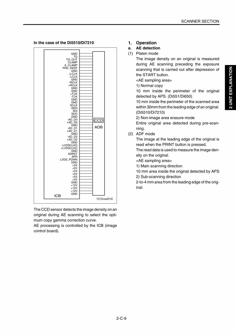
SCANNER SECTION
2-C-9
2 U
NIT
EX
PL
AN
AT
ION
In the case of the Di5510/Di7210
The CCD sensor detects the image density on anoriginal during AE scanning to select the opti-mum copy gamma correction curve.AE processing is controlled by the ICB (imagecontrol board).
1. Operationa. AE detection(1) Platen mode
The image density on an original is measuredduring AE scanning preceding the exposurescanning that is carried out after depression ofthe START button.<AE sampling area>1) Normal copy10 mm inside the perimeter of the originaldetected by APS. (Di551/Di650)10 mm inside the perimeter of the scanned areawithin 30mm from the leading edge of an original.(Di5510/Di7210)2) Non-image area erasure modeEntire original area detected during pre-scan-ning.
(2) ADF modeThe image at the leading edge of the original isread when the PRINT button is pressed.The read data is used to measure the image den-sity on the original.<AE sampling area>1) Main scanning direction10 mm area inside the original detected by APS2) Sub-scanning direction2-to-4 mm area from the leading edge of the orig-inal.
ICB
ADB
CCD
GNDTG
TG_OUTCLAMP
A_CLAMPPRD_KEEP
GND+LCLK-LCLK
GND-RCLK+RCLK
GNDGND
+TCK-TCKGNDGND
SCLK/SEN
SDISDOGND
-AD_D0+AD_D0
GND-AD_D1+AD_D1
GND-AD_D2+AD_D2
GND-LVDSCLKO+LVDSCLKO
GNDADRST
APRLVDS_PDWN
GND+5V+5V+5V+5V+5V+5V
GND+12V+12V+12VGND
7272ma2018

2 U
NIT
EX
PL
AN
AT
ION
Blank page

WRITE UNIT
2-D-1
2 U
NIT
EX
PL
AN
AT
ION
WRITE UNIT
[1] Composition
[2] Mechanisms
*1 Path of laser lightThe light output from the semiconductor laser isradiated onto the OPC drum via the collimatorlens, cylindrical lens 1, polygon mirror, fθ lens,cylindrical lens 2, and write mirror.
Index sensor board (INDXSB)Laser driver board (LDB)
Collimator lens unit
Cylindrical lens 1
Polygon mirror
Index mirrorf lens
Write mirror
Cylindrical lens 2
Mechanism Method
Scan*1 Polygon mirror
Light source*2 1-chip, 2-beam laser diode(Power: 15 mW per beam)
Reference posi-tioning
Index sensor
Semiconductor laser
Collimator lens
Write mirror
Cylindrical lens 1
Polygon mirror
Cylindrical lens 2
f lens

WRITE UNIT
2-D-2
2 U
NIT
EX
PL
AN
AT
ION
*2 Light sourceConventionally, two parallel beams were gener-ated from two laser beams. The laser diodeadopted for this machine can generate twobeams using a single chip, requiring neither fine-adjustment prism nor beam composition prism.
[3] M15 (Polygon) Control
M15 (polygon) is driven by PMDB (polygon driveboard) and is controlled by PRCB (printer controlboard).
1. Operationa. Explanation of operation
M15 is a 3-phase brushless DC motor which isdriven by the 3-phase bipolar method. The cur-rent flowing through the coil is switched accord-ing to the position of the rotor detected by theposition sensor (magnetic sensor) in the motor.This motor rotates the polygon mirror to scan thelaser beams from LDB (laser driver board) in theaxial direction of the drum. Its rotation is heldconstant by PLL control.
b. Rotational speedM15 is powered by 24 VDC and its rotationalspeed is as follows:In the case of the Di551/Di650
In the case of the Di5510/Di7210
Rotational speed
Linear speed
Di551 Di650
37,795 rpm 320 mm/s - normal
33,070 rpm 280 mm/s normal -
21,850 rpm 185 mm/s thick paper
Rotational speed
Linear speed
Di5510 Di7210
40,748 rpm 345 mm/s - normal
33,070 rpm 280 mm/s normal -
40,748 rpm 172.5 mm/s thick paper
PMDB
M15
PRCB
24V1P.GND
POLM CONTPOLM CLK
POLM LOCK
DCPS
24V/15V/2
S.GNDP.GND

WRITE UNIT
2-D-3
2 U
NIT
EX
PL
AN
AT
ION
2. Signalsa. Input signals(1) POLM_LOCK (PMDB to PRCB)
This signal indicates the clock synchronizationstate of M15 (polygon). [L]: Synchronous (normal)[H]: Asynchronous (abnormal)
b. Output signals(1) POLM_CONT (PRCB to PMDB)
This signal turns ON/OFF M15.[L]: M15 ON[H]: M15 OFF
(2) POLM_CLK (PRCB to PMDB)This is a reference clock signal for PLL-control-ling M15 in PMDB.
[4] Image Write ControlIn the case of the Di551/Di650
In the case of the Di5510/Di7210
ICB
INDXSB
5VSGND
/INDSGND
/INDPR
LDB
GNDVIDEO2
/VIDEO2GND
LPR5VLD5VLD5VGND
VIDEO1/VIDEO1
GND/ENB1/S/H1
/ALM1GND
/ENB2/S/H2
/ALM2GNDDADI
DACLKDALD
ADB
CCD
DCPS
24V15V2
S.GNDP.GND
7272ma2019
ICB
INDXSB
5VGND/INDGND
/INDPR
LDB
/ENB/ALM1/S/HB1
/S/H1GND
LD+5VLD+5V+5VRN
GND-VIDEO2+VIDEO2
GNDLOAD
DACLKDI
GND/ALM2/S/HB2
/S/H2/ALMRST
GND-VIDEO1+VIDEO1
GND
ADB
CCD
DCPS
24V15V2
S.GNDP.GND

WRITE UNIT
2-D-4
2 U
NIT
EX
PL
AN
AT
ION
The analog image data from the CCD sensor isA/D-converted by the ADB (A/D converterboard), then sent to the ICB (image controlboard) for data processing. The processedimage data is converted into a laser beam on theLDB (laser driver board), and then the beams areradiated onto the drum surface. Two beams areemitted per laser diode. Two lines of image datais written per scan.The write start reference position is detected bythe INDXSB (index sensor board). The ICB hasan E-RDH (electronic RDH) function to store dig-itized image data. Various editing functions canbe performed based on this data.

WRITE UNIT
2-D-5
2 U
NIT
EX
PL
AN
AT
ION
1. Operationa. Image processing
The following processing is performed by the ICB(image control board):
(1) AOC (Automatic Offset Control)The IC on the ADB (A/D converter board) auto-matically adjusts the analog offset voltage of theCCD sensor output so that it is at the lower limitof the A/D converter level.
(2) AGC (Automatic Gain Control)During shading correction, the white referenceplate is read to adjust the analog amplificationfactor of the CCD sensor output so that the readlevel is at the upper limit of the A/D converterlevel.
(3) Shading correction<Timing>• When SW2 (sub power) is ON• At job start
(4) Brightness/density conversion(5) AE processing(6) Text/dot pattern judgment(7) Filtering(8) Magnification change processing(9) Copy gamma correction (10) Skew correction(11) Error diffusion processing(12) Data compression/expansion processing (13) Write density controlb. Write
The ICB (image control board) sends image dataon a pixel basis to LDB (laser driver board)according to the control signals from the PRCB(printer control board).LDB causes the laser light to be emitted for aperiod corresponding to the image data. Thislaser light is radiated onto the drum surface.
(1) MPC (Maximum Power Control)ICB (image control board) informs LDB (laserdriver board) of the maximum output value andsets that value for the laser beam emission. LDBstore this value and maintain the laser beam levelusing the APC (Auto Power Control).<MPC timing>When SW2 (sub power switch) is turned ON
(2) APC (Automatic Power Control)After MPC is set, the ICB (image control board)outputs an APC start instruction to LDB (laserdriver board) at the following timing:<APC timing>LDB (laser driver board) automatically monitorthe laser drive current one line at a time, and con-trols it so that the light intensity remains the MPCvalue.
(3) Write timinga) Main scanning directionUsing INDEX signal (/IND) from INDXSB (indexsensor board), the laser write reference positionis determined for each scan in the drum rotationdirection, and the image is written onto the copypaper according to the copy paper positiondetected by PS70 (paper mis-centering).b) sub scanning directionSpecified interval after PS44 (registration)detects the leading edge of the copy paper.
2. Signalsa. Input signals(1) /IND (INDXSB to ICB)
This is an index signal used to detect deviation ofmain scanning.
(2) /INDPR (INDXSB to ICB)This signal monitors the INDXSB (index sensorboard) power supply.[H]: Abnormal[L]: Normal
(3) /ALM1 (LDB to ICB)This signal indicates the state of the laser 1 drivecurrent.[H]: Normal[L]: Abnormal
(4) LPR5V (LDB to ICB)This signal monitors the LDB (laser driver board)power supply.[H]: Normal[L]: Abnormal
(5) /ALM2 (LDB to ICB)This signal indicates the state of the laser 2 drivecurrent.[H]: Normal[L]: Abnormal

WRITE UNIT
2-D-6
2 U
NIT
EX
PL
AN
AT
ION
b. Output signals(1) /S/H1 (ICB to LDB)
APC sampling signal for one line (for laser 1)(2) /ENB1 (ICB to LDB)
Laser APC function ON/OFF control signal (forlaser 1)Laser beam emission stops when it is OFF.
(3) /S/H2 (ICB to LDB)APC sampling signal for one line (for laser 2)
(4) /ENB2 (ICB to LDB)Laser APC function ON/OFF control signal (forlaser 2)Laser beam emission stops when it is OFF.
(5) VIDEO1/VIDEO1 (ICB to LDB)Image signal for laser 1
(6) VIDEO2/VIDEO2 (ICB to LDB)Image signal for laser 2
(7) DACLK (ICB to LDB)LDB (laser driver board) MPC value data trans-mission clock signal
(8) DADI (ICB to LDB) LDB (laser driver board) signal for MPC
(9) DALD (ICB to LDB) LDB (laser driver board) MPC value memorycommand signal
(10) /S/HB1 (ICB to LDB)Sampling signal for laser bias current control(for laser 1) (Di5510/Di7210 only)
(11) /S/HB2 (ICB to LDB)Sampling signal for laser bias current control(for laser 2) (Di5510/Di7210 only)

DRUM UNIT
2-E-1
2 U
NIT
EX
PL
AN
AT
ION
DRUM UNIT
[1] Composition
[2] Mechanisms
The drum unit is an integral assembly consistingof a drum, charging corona unit, developing unit,cleaning/toner recycle unit, PCL, and separationclaws.
*1 Auxiliary separation• To prevent paper jamming, three separation
claws are used to separate paper from thedrum forcibly. These separation claws arepressed against the drum or detached from itby turning ON/OFF the separation claw sole-noid (SD1).
• To prevent a specific part of image-copiedpaper from being stained and to prevent thedrum from being scratched, the swing mecha-nism slides the separation claws about 8 mmback and forth in parallel with the drum sur-face.
*2 Transport assistanceThe thick paper conveyance ability has beenimproved by the use of ratchets.
Cleaning/toner recycle section
Charging corona unit
Developing unit
Drum
Separationclaw SD (SD1)
Separation claws
Toner guide roller (TGR)
Charging corona unit
DrumCleaning/toner recycle section Developing unit
Transfer and separation corona unit TSL
PCL
Mechanism Method
PCL/TSL LED
Auxiliary separa-tion *1
Separation claws
Transport assis-tance *2
Ratchet wheel
Separation claw SD (SD1)
Separation claws
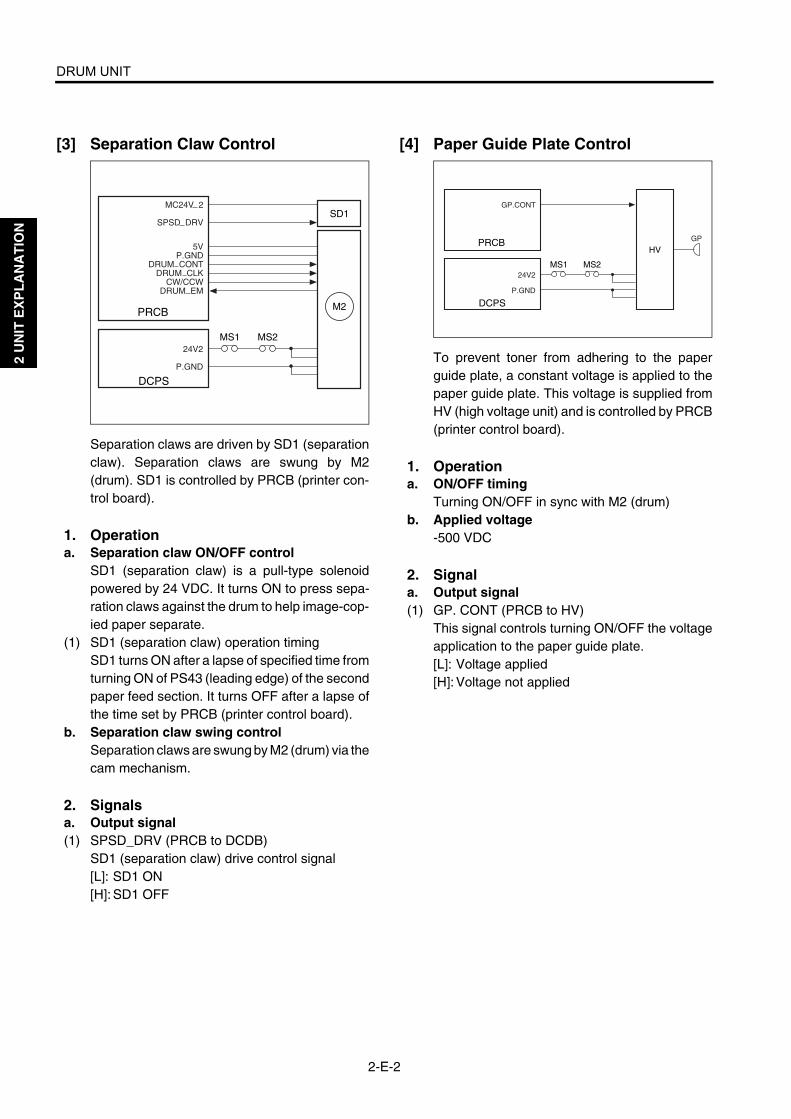
DRUM UNIT
2-E-2
2 U
NIT
EX
PL
AN
AT
ION
[3] Separation Claw Control
Separation claws are driven by SD1 (separationclaw). Separation claws are swung by M2(drum). SD1 is controlled by PRCB (printer con-trol board).
1. Operationa. Separation claw ON/OFF control
SD1 (separation claw) is a pull-type solenoidpowered by 24 VDC. It turns ON to press sepa-ration claws against the drum to help image-cop-ied paper separate.
(1) SD1 (separation claw) operation timingSD1 turns ON after a lapse of specified time fromturning ON of PS43 (leading edge) of the secondpaper feed section. It turns OFF after a lapse ofthe time set by PRCB (printer control board).
b. Separation claw swing controlSeparation claws are swung by M2 (drum) via thecam mechanism.
2. Signalsa. Output signal(1) SPSD_DRV (PRCB to DCDB)
SD1 (separation claw) drive control signal[L]: SD1 ON[H]: SD1 OFF
[4] Paper Guide Plate Control
To prevent toner from adhering to the paperguide plate, a constant voltage is applied to thepaper guide plate. This voltage is supplied fromHV (high voltage unit) and is controlled by PRCB(printer control board).
1. Operationa. ON/OFF timing
Turning ON/OFF in sync with M2 (drum)b. Applied voltage
-500 VDC
2. Signala. Output signal(1) GP. CONT (PRCB to HV)
This signal controls turning ON/OFF the voltageapplication to the paper guide plate.[L]: Voltage applied[H]: Voltage not applied
PRCB
DCPS
24V2
P.GND
MS1 MS2
M2
SD1
5VP.GND
DRUM CONTDRUM CLK
CW/CCWDRUM EM
MC24V 2
SPSD DRV
PRCB
DCPS
24V2
P.GND
GP
MS1 MS2
HV
GP.CONT

CORONA UNIT SECTION
2-F-1
2 U
NIT
EX
PL
AN
AT
ION
CORONA UNIT SECTION
[1] Composition
[2] Mechanisms
PCL
<Charging corona unit> <Transfer and separation corona unit>
Charging control plate
Charging corona wire
Transfer entrance guide plate
Guide rollers
Transfer corona wire
Plunging prevention plate (rear)
Separation corona wire
Plunging prevention plate (front)
Charging wire cleaning motor (M14)
Mechanism Method
Charging Scorotron (DC negative corona discharge)Discharging wire: Tungsten, 0.06 mm dia. (gold-plated skin path, with automatic wire cleaner)Grid control: Gold-plated stainless plate
Transfer DC positive corona dischargeDischarging wire: Oxide film tungsten, 0.06 mm dia., with automatic wire cleaner
Separation AC/DC corona dischargeDischarging wire: Oxide film tungsten, 0.06 mm dia., with automatic wire cleaner
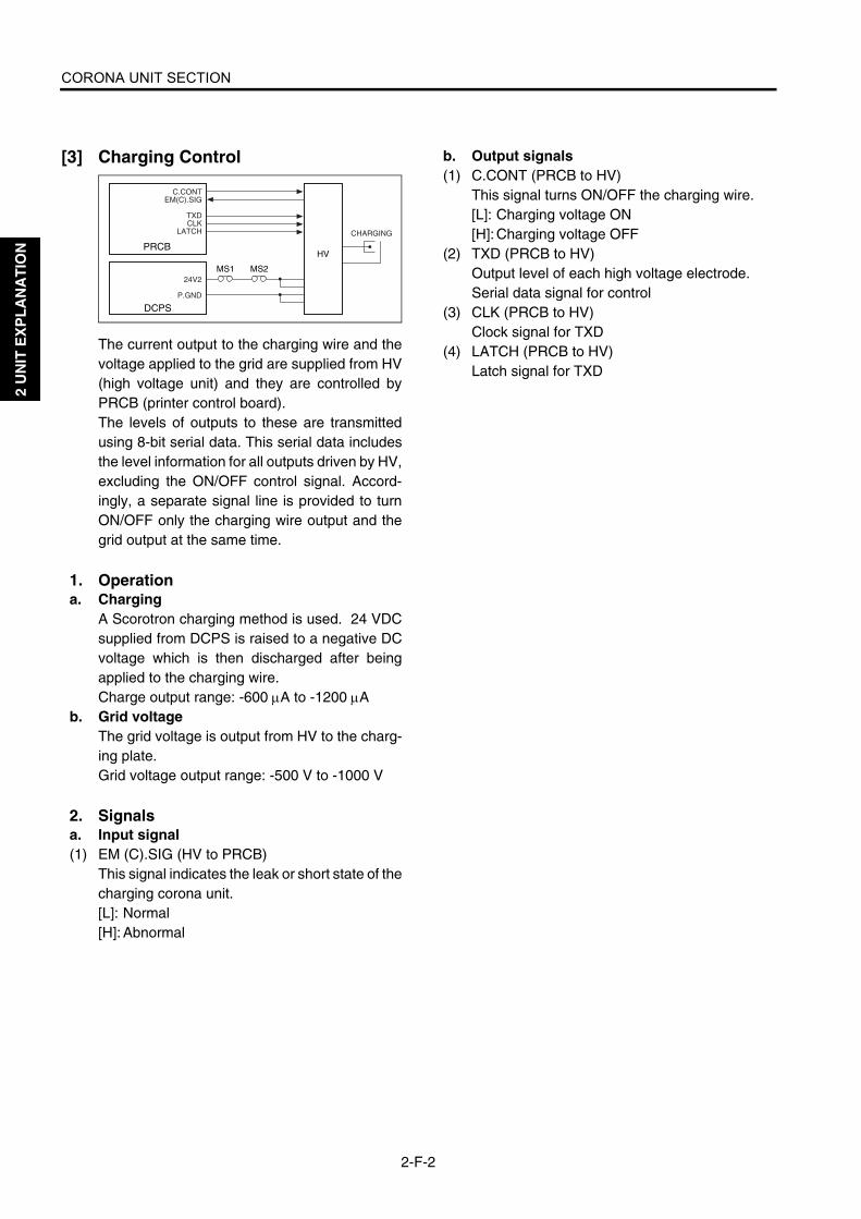
CORONA UNIT SECTION
2-F-2
2 U
NIT
EX
PL
AN
AT
ION
[3] Charging Control
The current output to the charging wire and thevoltage applied to the grid are supplied from HV(high voltage unit) and they are controlled byPRCB (printer control board).The levels of outputs to these are transmittedusing 8-bit serial data. This serial data includesthe level information for all outputs driven by HV,excluding the ON/OFF control signal. Accord-ingly, a separate signal line is provided to turnON/OFF only the charging wire output and thegrid output at the same time.
1. Operationa. Charging
A Scorotron charging method is used. 24 VDCsupplied from DCPS is raised to a negative DCvoltage which is then discharged after beingapplied to the charging wire.Charge output range: -600 µA to -1200 µA
b. Grid voltageThe grid voltage is output from HV to the charg-ing plate.Grid voltage output range: -500 V to -1000 V
2. Signalsa. Input signal(1) EM (C).SIG (HV to PRCB)
This signal indicates the leak or short state of thecharging corona unit.[L]: Normal[H]: Abnormal
b. Output signals(1) C.CONT (PRCB to HV)
This signal turns ON/OFF the charging wire.[L]: Charging voltage ON[H]: Charging voltage OFF
(2) TXD (PRCB to HV)Output level of each high voltage electrode.Serial data signal for control
(3) CLK (PRCB to HV)Clock signal for TXD
(4) LATCH (PRCB to HV)Latch signal for TXD
PRCB
DCPS
24V2
P.GND
CHARGING
MS1 MS2
HV
C.CONTEM(C).SIG
TXDCLK
LATCH

CORONA UNIT SECTION
2-F-3
2 U
NIT
EX
PL
AN
AT
ION
[4] Transfer/Separation Control
The voltages applied to the transfer wire andseparation wire is supplied from HV (high voltageunit) and are controlled by PRCB (printer controlboard). The levels of outputs to these wires aretransmitted using 8-bit serial data. This serialdata includes the level information for all outputsdriven by HV, excluding the ON/OFF control sig-nal. Accordingly, a separate signal line is pro-vided to turn ON/OFF only the transfer wire orseparation wire.
1. Operationa. Transfer
Positive DC high voltage is used for transfer.Transfer DC output range: 50 µA to 600 µA
b. SeparationAC high voltage and negative DC voltage areused for separation.Separation AC output range: 4kV to 5.7kVSeparation DC output range: 0 µA to -400 µA
2. Signalsa. Input signals(1) EM (T) .SIG (HV to PRCB)
This signal indicates the leak or short state of thetransfer corona unit.[L]: Normal[H]: Abnormal
(2) EM (S) .SIG (HV to PRCB)This signal indicates the leak or short state of theseparation corona unit.[L]: Normal[H]: Abnormal
b. PRCB output signals(1) T.CONT (PRCB to HV)
This signal turns ON/OFF the voltage applied tothe transfer wire.[L]: Transfer voltage ON[H]: Transfer voltage OFF
(2) S.CONT (PRCB to HV)This signal turns ON/OFF the voltage applied tothe separation wire.[L]: Separation voltage ON[H]: Separation voltage OFF
PRCB
DCPS
24V2
P.GND
TRANSFER
SEPARATION
MS1 MS2
HV
T.CONTEM(T).SIG
S.CONTEM(S).SIG
TXDCLK
LATCH

CORONA UNIT SECTION
2-F-4
2 U
NIT
EX
PL
AN
AT
ION
[5] M14 (Charger Cleaning) Control
M14 (charger cleaning) is a DC motor poweredby 24 VDC and is controlled by PRCB (printercontrol board).
1. Operationa. Purpose of driving
M14 (charger cleaning) is used to drive thecharging wire cleaning unit.
b. Operation timingThe charging wires are cleaned when SW2 (subpower) is turned ON and when the fixing temper-ature is lower than 50°C. They are also cleanedafter the specified copy count is reached.* Changeable with the 25-mode DIP SW
c. Cleaning operationNormally, the charging wire cleaning unit is onthe front side of the machine. It moves back andforth to clean the charging wires. The movementdirection is changed by changing the rotationaldirection of M14 (charge cleaning).The rotational direction of M14 and the positionof the cleaner are detected by monitoring the cur-rent value of M14 with PRCB (printer controlboard).
2. Signalsa. Output signal(1) CHGM_A, B (PRCB to M14)
M14 (charger cleaning) drive control signal.The drive direction of M14 is controlled by switch-ing between the drive current directions of twosignals.
M14
PRCB
CHGM ACHGM B
DCPS
24V/15V/2
S.GNDP.GND
Status CHGM_A CHGM_B
Forward stroke of cleaning H L
Backward stroke of cleaning L H
Stop L L

CORONA UNIT SECTION
2-F-5
2 U
NIT
EX
PL
AN
AT
ION
[6] M10 (Transfer/Separation Cleaning) Control
M10 (transfer/separation cleaning) is a DC motorpowered by 24 VDC and is controlled by PRCB(printer control board) via ADUDB (ADU driveboard). Between PRCB and ADUDB, signals areexchanged using serial data.
1. Operationa. Purpose of driving
M10 (transfer/separation cleaning) used to drivethe transfer/separation wire cleaning pads.
b. Operation timingThe transfer/separation wires are cleaned whenSW2 (sub power) is turned ON or when the fixingtemperature is lower than 50°C.It is also carried out after the specified copy countis reached.* Changeable with the 25-mode DIP SW
c. Cleaning operation Normally, the transfer/separation wire cleaningpads are on the front side of the machine. Theymove back and forth to clean the transfer andseparation wires. The movement direction ischanged by changing the rotational direction ofM10 (transfer/separation cleaning).The rotational direction of M10 and the positionof the cleaner are detected by monitoring the cur-rent value of M10 with PRCB (printer controlboard). (Di551/Di650)
The rotational direction of M10 and the positionof the cleaner are detected by turning on/off thePS52 (transfer/separation PS/F) and PS53(transfer/separation PS/R). (Di5510/Di7210)
2. Signals a. Input signals(1) IO_URXD (ADUDB to PRCB)
Serial data used to report the ADUDB (ADUdrive board) operation state to PRCB (printercontrol board)
(2) REQ1 (ADUDB to PRCB)This signal indicates that sending data fromADUDB (ADU drive board) to PRCB (printer con-trol board) is requested.When ADUDB receives ACK1 and can senddata, this signal stands at the [L] level.
(3) IO_UCLK (ADUDB to PRCB)Clock signal for IO_URXD signal
(4) HP_PS_F (PS52 to ADUDB)Home position detection signal of transfer/sepa-ration cleaning memberIt becomes L when transfer/separation cleaningmember reaches the home position.
(5) HP_PS_R (PS53 to ADUDB)Reverse position detection signal of transfer/separation cleaning memberIt becomes L when transfer/separation cleaningmember reaches the reverse position.
7272ma2003
ADUDB
SEP CLM M ASEP CLM M B
5V2 HP_PS_F
SGND
5V2HP_PS_R
SGND
PRCB
IO DTXDIO DCLK
ADU LATCHIO UCLK
REQ1IO URXD
ACK1ERR OUT1
DCPS
24V15V2
S.GNDP.GND
5V2S.GND
M10
PS52
(Di5510/Di7210)
PS53

CORONA UNIT SECTION
2-F-6
2 U
NIT
EX
PL
AN
AT
ION
b. Output signals(1) SEP_CLM_M A, B (ADUDB to M10)
M10 (transfer/separation cleaning) drive controlsignalThe drive direction of M10 (transfer/separationcleaning) drive control signalThe drive direction of M10 is controlled by switch-ing between the drive current directions of twosignals.
(2) IO_DTXD (PRCB to ADUDB)Serial data used to report the machine operationstate understood by PRCB (printer controlboard) to ADUDB (ADU drive board)
(3) IO_DCLK (PRCB to ADUDB)Clock signal for IO_DTXD signal
(4) ADU_LATCH (PRCB to ADUDB)Latch signal for IO_DTXD signal
(5) ACK1 (PRCB to ADUDB)Reception acknowledgment signal. It is senteach time PRCB (printer control board) receivesone-byte data from ADUDB (ADU drive board).When PRCB receives REQ1 and can receivedata, this signal stands at the [L] level.
(6) ERR_OUT1 (PRCB to ADUDB)This signal requires resending of data whenPRCB (printer control board) has failed in datareception from ADUDB (ADU drive board) due toan error.
[7] PCL/TSL Control
LEDs are used for PCL (pre-charging exposurelamp) and TSL (transfer synchronization lamp).PCL is driven by the PRCB (printer controlboard). TSL is driven by ADUDB (ADU driveboard). PCL and TSL are controlled by PRCB .
1. OperationPCL turns ON when the START button ispressed. It is turned OFF after a lapse of thespecified time from turning ON of PS37 (paperexit). TSL turns ON after a lapse of the specifiedtime from turning ON of PS43 (leading edge) ofthe second paper feed section. It turns OFF aftera lapse of the specified time from detection of thetrailing edge of copy paper.
2. Signalsa. Output signals(1) PCL CONT (PRCB to PCL)
PCL ON/OFF control signal[L]: PCL ON[H]: PCL OFF
(2) TSL_DR (ADUDB to TSL)TSL ON/OFF control signal[L]: TSL ON[H]: TSL OFF
Status SEP_CLM_MA SEP_CLM_MB
Forward stroke of cleaning H L
Backward stroke of cleaning L H
Stop L LADUDB
MC24V
TSL DRPRCB
IO DTXDIO DCLK
ADU LATCHIO UCLK
REQ1IO URXD
ACK1ERR OUT1
MC 24V2
PCL CONT
DCPS
24V15V2
S.GNDP.GND
5V2S.GND
24V1P.GND
TSL
PCL

DEVELOPING UNIT
2-G-1
2 U
NIT
EX
PL
AN
AT
ION
DEVELOPING UNIT
[1] Composition
[2] Mechanisms
1. Developing driveThe developing motor (M3) drives the followingparts via the gear unit at the back:• Developing sleeve• Agitator wheel• Agitator screws
2. Flow of developerThe developer inside the developing unit is sup-plied to the developing sleeve by the agitatorwheel, and maintained at a constant thickness bythe developer regulation plate (bristle height reg-ulation plate). The developer remaining on thedeveloping sleeve is returned to the agitatorscrews.
Splash prevention sheet (upper)
Developing regulation plate
Developing sleeve
Agitator wheel Agitator
screws
Developing unit cover
Agitator screws
Developing sleeve Developing regulation plate
Mechanism Method
Developing 2-component developer
Developing bias DC bias
Developeragitation
Main agitatorAuxiliary agitator
Splash prevention sheet (upper)
Developing regulation plate
Developing sleeve
Agitator wheel Agitator
screws

DEVELOPING UNIT
2-G-2
2 U
NIT
EX
PL
AN
AT
ION
[3] M3 (Developing) Control
M3 (developing) is controlled by PRCB (printercontrol board) and the motor drive power is sup-plied from DCPS (DC power supply unit).
1. Operation M3 (developing) is a DC motor driven by 24 V. Itdrives the developing sleeve, agitator wheel, andagitator screws. M3 turns ON when the PRINT button is pressed,and turns OFF after lapse of the specified timefrom turning OFF of the charging.
2. Signalsa. Input signals(1) DEVM_EM (M3 to PRCB)
M3 (developing) abnormality detection signal[H] Abnormal rotation (when motor speed
changes by 6.5% more or less than the motorspeed specified value)
[L] Normal rotationb. Output signals(1) DEVM_CONT (PRCB to M3)
M3 (developing) drive control signal[L] M3 ON[H] M3 OFF
(2) DEVM_CLK (PRCB to M3)M3 (developing) rotational speed control clocksignal
(3) DEVM_CW/CCW (PRCB to M3)M3 (developing) rotational direction indicationsignal[H]: CW direction rotation[L]: CCW direction rotation
(4) EDVM_GAIN (PRCB to M3)M3 (developing) rotational speed range indica-tion signal[H]: High speed range[L]: Low speed range
PRCB
DCPS
24V2
P.GND
MS1 MS2
M3
5VP.GND
DEVM CONTDEVM CLK
DEVM CW/CCWDEVM GAIN
DEVM EM

DEVELOPING UNIT
2-G-3
2 U
NIT
EX
PL
AN
AT
ION
[4] Developing Bias Control
The developing bias voltage is supplied from HV(high voltage unit) and is controlled by PRCB(printer control board). The output level of thedeveloping bias voltage is transmitted using 8-bitserial data. This serial data includes the levelinformation for all outputs driven by HV, excludingthe ON/OFF control signal. Accordingly, a sepa-rate signal line is provided to turn ON/OFF onlythe developing bias.
1. OperationApplication of the developing bias voltage startsafter a lapse of the specified time from turningON of the START button, and stops after a lapseof the specified time from turning OFF of PS43(leading edge) by the last copy paper.Developing bias output range: -300 V to -700 V
2. Signalsa. Output signal(1) B.CONT (PRCB to HV)
Developing bias output ON/OFF control signal.[L]: Developing bias ON[H]:Develpoing bias OFF
PRCB
DCPS
24V1
P.GND
BIAS
HV
B.CONT
TXDCLK
LATCH

DEVELOPING UNIT
2-G-4
2 U
NIT
EX
PL
AN
AT
ION
[5] Dmax Control
Dmax control is performed by TCSB (toner con-trol sensor board), M2 (drum), M3 (developing),and so on under the control of PRCB (printercontrol board).
1. OperationThe purpose of Dmax control is to adjust themaximum density to the reference level for eachmachine.
a. Dmax control(1) Method
Several latent images are created at the maxi-mum laser power, images are developed with therotational speed of the developing sleeve varied,then each density is read by the Dmax sensor(PD1) on TCSB (toner control sensor board).The developing sleeve speed detected when thedensity has reached the reference level isrecorded as the optimum sleeve speed, allowingdeveloping to be performed at this sleeve speed.
(2) Timinga) When the fixing temperature is lower than
50°C at SW2 (sub power) ONb) Every 10,000 prints, upon completion of the
last job.
PRCB
TCSB
DCPS
24V2
P.GND
12V2S.GND
MS1 MS2
M3
M2
5VP.GND
DEVM CONTDEVM CLK
DEVM CW/CCWDEVM GAIN
DEVM EM
5VP.GND
DRUM CONTDRUM CLK
CW/CCWDRUM EM
12VA.GNDDMLED CONTDM MONI EXDJLED CONTDM SIG EXDRUM JSIG EXTNLED REFTEMP3.3V2

DEVELOPING UNIT
2-G-5
2 U
NIT
EX
PL
AN
AT
ION
2. Signalsa. Input signals(1) DM_SIG_EX (TCSB to PRCB)
Output voltage of Dmax detection sensor (PC1)on TCSB (toner control sensor board)Reference voltage: 2.5 V
(2) DM_MONI_EX (TCSB to PRCB)This signal monitors the light reflected by thedrum surface (without toner).The voltage applied to the Dmax detection LEDis corrected by TNLED_REF so that the outputvoltage becomes 1.9 V (calibration).Reference voltage: 1.9 V<Timing>Before Dmax correction
(3) DRUM_JSIG_EX (TCSB to PRCB)This signal detects a jam caused by paper wrap-ping around the drum. A jam is detected whenthe voltage becomes 4.0 V or more.
(4) TEMP, 3.3V2 (TCSB to PRCB)Drum temperature detection signal
b. Output signals(1) DMLED CONT (PRCB to TCSB)
Dmax LED ON/OFF control signal[L]: LED ON[H]: LED OFF
(2) TNLED_REF (PRCB to TCSB)Power supply line for PD1 LED on TCSB.The voltage is adjusted so that the Dmax MONIsignal becomes 1.9 V.
(3) DJLED_CONT (PRCB to TCSB)JAM LED ON/OFF control signal[L]: LED ON[H]: LED OFF

DEVELOPING UNIT
2-G-6
2 U
NIT
EX
PL
AN
AT
ION
[6] Gradation Correction Control
Gradation correction control is performed byTCSB (toner control sensor board), M2 (drum),M3 (developing), and so on under the control ofPRCB (printer control board).
1. OperationThe gradation characteristics of the toner densityversus exposure amount at the image formingsection (drum area) are detected to obtain a lin-ear relation between the image density on a doc-ument and the copying image density.
(1) MethodExposure is performed with the laser PWM var-ied in several steps, and development is per-formed at the sleeve speed obtained by Dmaxcorrection.Next, each density is read by the γ sensor (PD2)on TCSB (toner control sensor board) to detectthe gradation characteristics of image density.The gradation characteristics obtained here areused as the values for correcting the laser expo-sure amount.Gradation correction control must be performedin two ways: 1-dot PWM (for normal mode) and2-dot PWM (for photo mode).
(2) Timinga) When the fixing temperature is lower than
50°C at SW2 (sub power) ONb) Every 5,000 prints, upon competion of the
last job.
2. Signalsa. Input signals(1) G_SIG_EX (TCSB to PRCB)
This signal monitors the output voltage from theγ sensor (PD2) on the TCSB (toner control sen-sor board) as well as the light reflected by thedrum surface (without toner).The voltage applied to the gradation detectionLED is corrected by TNLED_REF so that the out-put voltage becomes 3.0 V (calibration).Reference voltage: 3.0 V<Timing>Before gradation correction.
b. Output signal(1) γ LED CONT (PRCB to TCSB)
Gradation detection LED ON/OFF control signal[L]: LED ON[H]: LED OFF
PRCB
TCSB
DCPS
24V2
P.GND
12V2S.GND
MS1 MS2
M3
M2
5VP.GND
DEVM CONTDEVM CLK
DEVM CW/CCWDEVM GAIN
DEVM EM
5VP.GND
DRUM CONTDRUM CLK
CW/CCWDRUM EM
12VA.GND
G SIG EX LED CONT
TNLED REF

DEVELOPING UNIT
2-G-7
2 U
NIT
EX
PL
AN
AT
ION
[7] Dot Diameter Correction Control
Dot diameter is detected by TCSB (toner controlsensor board) and is controlled by PRCB (printercontrol board).
1. OperationDot diameter correction is performed to preventthe 1-dot laser beam diameter from fluctuatingdue to the change in developing characteristics(caused by deteriorated developer) and soil inthe write unit.
(1) MethodMultiple dot pattern patches with the same con-densation are created to be read by the γ sensor(PD2). The laser power where the γ sensor out-put reaches the reference voltage is used as theMPC value.
(2) Timinga) Every 10,000 prints, upon completion of the
last job.
[8] Toner Density Control
The density of toner is controlled by controllingM12 (toner supply) from PRCB (printer controlboard).
1. Operationa. Toner density detection
The reference patch density is detected usingthe patch detection method of TCSB (toner con-trol sensor board) and the corresponding analogvoltage signal is output to PRCB (printer controlboard), thus detecting the toner density.The PRCB compares the detected voltage withthe reference value to determine whether tonermust be added.
b. Toner supply operationUpon read of the patch, M12 (toner supply) isturned ON to supply toner. The time needed toadd toner depends on the paper size.
2. Signalsa. Output signals(1) TNSM_A, AB (PRCB to M12)
A-phase drive signal of M12 (toner supply)(2) TNSM_B, BB (PRCB to M12)
B-phase drive signal of M12 (toner supply)
PRCB
TCSB
DCPS
12V2S.GND
12VA.GND
G SIG EX LED CONT
TNLED REF
M12
PRCB
TNSM24VTNSM24V
TNSM ATNSM AB
TNSM BTNSM BB
DCPS
24V15V2
S.GNDP.GND
TCSB
12VA.GNDDMLED CONTDM MONI EXDJLED CONTDM SIG EXDRUM JSIG EXTNLED REFTEMP3.3V2

DEVELOPING UNIT
2-G-8
2 U
NIT
EX
PL
AN
AT
ION
[9] FM4 (Developing Suction) Control
FM4 (developing suction) is controlled by PRCB(printer control board).
1. Operationa. ON timing
FM4 (developing suction) is turned ON when M2(drum) is turned ON.
b. OFF timingFM4 (developing suction) is turned OFF after alapse of the specified time from turning OFF ofM2 (drum).
2. Signalsa. Input signal(1) FM2 EM (FM4 to PRCB)
FM4 (developing suction) abnormality detectionsignal[L]: FM4 is normal.[H]: FM4 is abnormal.
b. Output signal(1) SUCTFAN_D (ACDB to FM4)
FM4 (developing suction) drive signal[L]: FM4 OFF[H]: FM4 ON
FM4
PRCB
SUCTFAN D
SFAN EM
P.GND
DCPS
24V15V2
S.GNDP.GND

TONER SUPPLY UNIT
2-H-1
2 U
NIT
EX
PL
AN
AT
ION
TONER SUPPLY UNIT
[1] Composition
[2] Mechanisms
*1 Toner agitationToner agitator plates are driven by the followingtwo motors through the gear unit:a) Toner supply motor (M12): Drives the toner
supply screws.b) Toner bottle motor (M13): Drives the toner
cartrdge.The agitator plates prevent toner from solidifyingand collecting on the toner level detection sensor(TLD).
Toner cartridge
Toner supply motor (M12) Toner supply screws
Toner level detection sensor (TLD)
Hopper
Toner bottle motor (M13)
Mechanism Method
Toner supply Supply by screw
Toner level detection Piezoelectric method100 ± 25 g
Toner agitation*1 Agitator plate
Toner cartridge*2 Rotary cartridgeCapacity: 1000 g
Toner leakageprevention
Toner supply shutter
Toner cartridge
Toner supply screws
Toner bottle motor (M13)
Toner supply motor (M12)
Agitator plate

TONER SUPPLY UNIT
2-H-2
2 U
NIT
EX
PL
AN
AT
ION
*2 Toner cartridgeWhen the toner cartridge rotates, toner is fed tothe outlet of the cartridge through the spiralgroove on the surface of the toner cartridge.When the outlet of the cartridge faces downward,toner flows out of the outlet into the agitation/con-veyance section of the toner supply unit.
[3] Toner Level Detection Control
Toner level detection is controlled by the TLD(toner level detection sensor) and the PRCB(printer control board).
1. Operationa. Toner level detection
A piezoelectric device is used as the TLD (tonerlevel detection sensor).When the level of toner in the hopper becomeslow, the toner supply signal is output to PRCB(printer control board). As a result, a message isdisplayed on the LCD connected to OB1 (oper-ation board/1).
b. Detection timingThe detection timing is as follows:• Power-on• When the front door opens or closes• During copying
c. Toner supply to toner supply unitWhen the no toner state is detected by TLD(toner level detection sensor), M13 (toner bottle)is turned ON to supply toner from the toner car-tridge to the toner supply unit.
d. Detection of no toner state in toner cartridgeIf the no toner state is detected by TLD (tonerlevel detection) after M13 has been held ON fora specified period of time, the toner cartridge isassumed to be empty.
Outlet
90 rotation
To agitation/conveyance block of toner supply unit
PRCB
DCPS
24V2
P.GND
MS1 MS2
M13
TLD
5VP.GND
TONERM CONTTONERM CLK
TONERM CW/CCWTONERM EM
S.GNDTONER SIG
T SENSE CONT
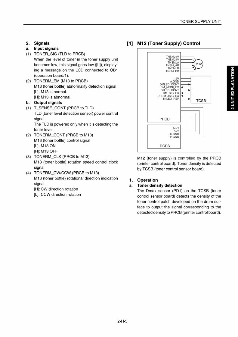
TONER SUPPLY UNIT
2-H-3
2 U
NIT
EX
PL
AN
AT
ION
2. Signalsa. Input signals(1) TONER_SIG (TLD to PRCB)
When the level of toner in the toner supply unitbecomes low, this signal goes low ([L]), display-ing a message on the LCD connected to OB1(operation board/1).
(2) TONERM_EM (M13 to PRCB)M13 (toner bottle) abnormality detection signal[L]: M13 is normal.[H]: M13 is abnormal.
b. Output signals(1) T_SENSE_CONT (PRCB to TLD)
TLD (toner level detection sensor) power controlsignalThe TLD is powered only when it is detecting thetoner level.
(2) TONERM_CONT (PRCB to M13)M13 (toner bottle) control signal[L]: M13 ON[H]: M13 OFF
(3) TONERM_CLK (PRCB to M13)M13 (toner bottle) rotation speed control clocksignal
(4) TONERM_CW/CCW (PRCB to M13)M13 (toner bottle) rotational direction indicationsignal[H]: CW direction rotation [L]: CCW direction rotation
[4] M12 (Toner Supply) Control
M12 (toner supply) is controlled by the PRCB(printer control board). Toner density is detectedby TCSB (toner control sensor board).
1. Operationa. Toner density detection
The Dmax sensor (PD1) on the TCSB (tonercontrol sensor board) detects the density of thetoner control patch developed on the drum sur-face to output the signal corresponding to thedetected density to PRCB (printer control board).
PRCB
TCSB
DCPS
M12
12VA.GND
DMLED CONTDM MONI EXDJLED CONT
DM SIG EXDRUM JSIG EX
TNLED REF
TNSM24VTNSM24V
TNSM ATNSM AB
TNSM BTNSM BB
24V15V2
S.GNDP.GND

TONER SUPPLY UNIT
2-H-4
2 U
NIT
EX
PL
AN
AT
ION
b. Toner supplyWhen the voltage detected by TCSB (toner con-trol sensor board) is below the specified value,PRCB issues a control signal to drive M12 (tonersupply). The relationship between the paper sizeand toner supply time is summarized in the fol-lowing table:
Paper size Supply time (sec.)
A3 1.30
B4 0.98
F4 0.98
A4 0.65
B5 0.49
B5R 0.49
A5 0.33
11 X 17 1.30
8.5 X 14 0.98
8.5 X 11 0.65
5.5 X 8.5 0.49
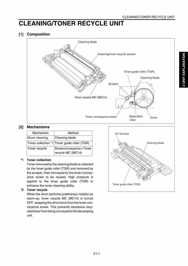
CLEANING/TONER RECYCLE UNIT
2-I-1
2 U
NIT
EX
PL
AN
AT
ION
CLEANING/TONER RECYCLE UNIT
[1] Composition
[2] Mechanisms
*1 Toner collectionToner removed by the cleaning blade is collectedby the toner guide roller (TGR) and removed bythe scraper, then conveyed by the toner convey-ance screw to be reused. High pressure isapplied to the toner guide roller (TGR) toenhance the toner cleaning ability.
*2 Toner recycleWhen the drum performs preliminary rotation aswarm-up, toner recycle MC (MC14) is turnedOFF, stopping the drive force from the toner con-veyance screw. This prevents excessive recy-cled toner from being conveyed to the developingunit.
Cleaning blade
Cleaning/toner recycle section
Toner guide roller (TGR)
Cleaning blade
Scraper
Toner conveyance screw Separation claw
Drum
Toner recycle MC (MC14)
Mechanism Method
Drum cleaning Cleaning blade
Toner collection *1 Toner guide roller (TGR)
Toner recycle Screw conveyance + Toner recycle MC (MC14)
Toner guide roller (TGR)
Cleaning blade
HV Terminal

CLEANING/TONER RECYCLE UNIT
2-I-2
2 U
NIT
EX
PL
AN
AT
ION
[3] TGR (Toner Guide Roller) Control
To enhance the toner cleaning ability, voltage isapplied to the TGR (toner guide roller). This volt-age is applied by HV (high voltage unit) under thecontrol of PRCB (printer control board). The out-put level of the applied voltage is transmittedusing 8-bit serial data. This serial data includesthe level information for all outputs driven by theHV unit excluding the ON/OFF control signal.Accordingly, a separate signal line is provided toturn ON/OFF only the TGR.
1. Operationa. ON/OFF timing
The TGR is turned ON/OFF in sync with M2(drum).
b. TGR (toner guide roller) output range0 to 50 µA
2. Signalsa. Output signal(1) TGR.CONT (PRCB to HV)
TGR (toner guide roller) voltage ON/OFF controlsignal[L]: Voltage is applied.[H]: Voltage is not applied.
[4] Other Control To improve durability of the cleaning blade, thefollowing control is performed:
a. Blade setting modeA blade setting mode is available in the 36 mode.This mode will perform a task that is requiredafter blade replacement during maintenance,etc. When this mode is used, toner adheres onthe drum and then the blade cleans the drum,preventing blade peeling.
b. Black stripe creation controlTo improve durability of the blade (stabilize loadand stabilize paper dust crushing), a black stripeof toner is adhered on the drum and thencleaned.Di551/Di650: once every 10 copies Di5510/Di7210: once every 12 copies * Changeable with the 25-mode DIP SW
PRCB
DCPS
24V2
P.GND
TGR
MS1 MS2
HV
TGR.CONTTXDCLK
LATCH
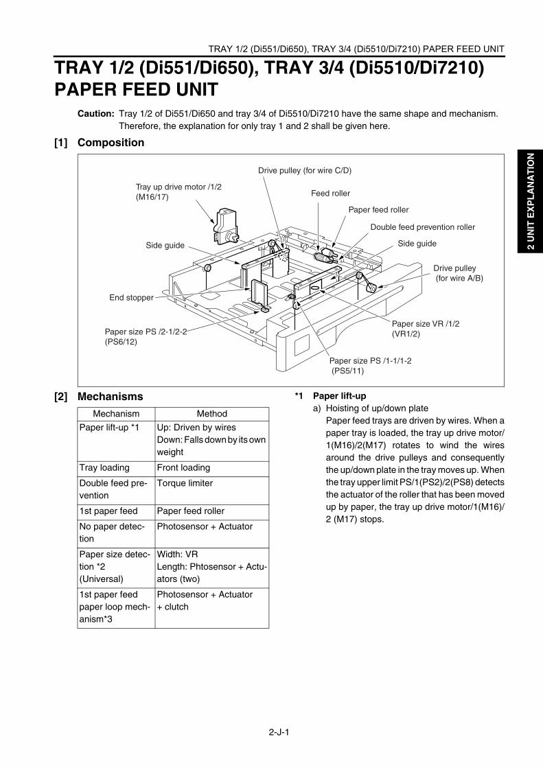
TRAY 1/2 (Di551/Di650), TRAY 3/4 (Di5510/Di7210) PAPER FEED UNIT
2-J-1
2 U
NIT
EX
PL
AN
AT
ION
TRAY 1/2 (Di551/Di650), TRAY 3/4 (Di5510/Di7210) PAPER FEED UNIT
Caution: Tray 1/2 of Di551/Di650 and tray 3/4 of Di5510/Di7210 have the same shape and mechanism. Therefore, the explanation for only tray 1 and 2 shall be given here.
[1] Composition
[2] Mechanisms *1 Paper lift-upa) Hoisting of up/down plate
Paper feed trays are driven by wires. When apaper tray is loaded, the tray up drive motor/1(M16)/2(M17) rotates to wind the wiresaround the drive pulleys and consequentlythe up/down plate in the tray moves up. Whenthe tray upper limit PS/1(PS2)/2(PS8) detectsthe actuator of the roller that has been movedup by paper, the tray up drive motor/1(M16)/2 (M17) stops.
End stopper
Drive pulley (for wire C/D)
Tray up drive motor /1/2 (M16/17) Feed roller
Paper feed roller
Double feed prevention roller
Side guideSide guide
Drive pulley (for wire A/B)
Paper size PS /2-1/2-2(PS6/12)
Paper size VR /1/2(VR1/2)
Paper size PS /1-1/1-2 (PS5/11)
Mechanism Method
Paper lift-up *1 Up: Driven by wiresDown: Falls down by its own weight
Tray loading Front loading
Double feed pre-vention
Torque limiter
1st paper feed Paper feed roller
No paper detec-tion
Photosensor + Actuator
Paper size detec-tion *2(Universal)
Width: VRLength: Phtosensor + Actu-ators (two)
1st paper feed paper loop mech-anism*3
Photosensor + Actuator+ clutch

TRAY 1/2 (Di551/Di650), TRAY 3/4 (Di5510/Di7210) PAPER FEED UNIT
2-J-2
2 U
NIT
EX
PL
AN
AT
ION
b) Lowering of trayWhen the paper feed tray is pulled out, thecoupling shaft of the tray is disengaged fromthe coupling gear of the tray up drive motor onthe main body side, allowing the up/downplate in the tray to fall down by its own weight.
*2 Paper size detectionLength: When paper pushes the paper size
detection actuator, the paper size PS/2-1/2-2 (PS6/PS12) and the paper sizePS/1-1/1-2 (PS5/PS11) turn ON. Thus,the paper size is automatically deter-mined according to the combination ofthe ON/OFF states of these PSs.
Width: When the side guides of the tray are slid,the rack gear of the side guide (front)turns the paper size VR/1/2 gear. Thus,the paper size is automatically deter-mined according to the change in theresistance value of the VR.
*3 First paper feed paper loop mechanismWhen paper feed starts, paper is fed to the pre-registration roller by the feed roller and paperfeed rollers. The fed out paper operates theactuator of the paper feed PS/1 (PS1), the paperfeed PS/2 (PS7) turning it ON. The feed andpaper feed rollers remain ON for a specified timeafter the actuation of the paper feed PS/1 (PS1)and PS/2 (PS7) causing a paper loop to formagainst the pre-registration rollers which are notturning. In this way paper skew is corrected.
Coupling gear
[Main body side]
Coupling[Tray side]
Paper size VR gear
Rack gear
Side guide (front)
Feed roller
Pre-registration roller
Paper feed roller
Paper feed PS/1(PS1), /2 (PS7)

TRAY 1/2 (Di551/Di650), TRAY 3/4 (Di5510/Di7210) PAPER FEED UNIT
2-J-3
2 U
NIT
EX
PL
AN
AT
ION
[3] First Paper Feed Control
The 1st paper feed from tray 1/2 takes place asthe result of the transmission of the drive forcefrom M1 (paper feed) to each paper feed roller byMC3/5 (paper feed MC/1/2) and MC4/6(pre-reg-istration MC/1/2). The feed roller picks up paperusing its own weight.The above operations are controlled by thePRCB (printer control board). Related signalsare PS1/7 (paper feed/1/2) and PS25/26 (verti-cal conveyance/1/2) issued from the vertical con-veyance section.
1. Operationa. Operation of the MC3/5 (paper feed MC/1/2)(1) Start timing of printing of the first copy
MC3/5 (paper feed MC/1/2) turns ON at the tim-ing that is determined by the P counter fromwhen copying starts, and turns OFF after a lapseof the specified time from PS1/7 (paper feed/1/7)turning OFF. Thus, paper skew is corrected byforming the loop before pre-registration roller.
(2) Start timing of printing of the second copyWhen the preceding paper turns OFF PS1/7.
(3) OFF timingWhen PS1/7 is turned ON.
b. Operation of the MC4/6 (pre-registrationMC1/2)
(1) ON timingAfter a specified time from MC3/5 (paper feedMC/1/2) turning ON.
(2) OFF timingWhen PS1/7 (paper feed/1/2) is turned OFF.
PS7
MC6
MC5
PS1
MC4
MC3
PRCB
DCPS
24V1P.GND
5V2S.GND
24V2P.GND
FEEDM_CONTFEEDM_CLKFEEDM_F/EFEEDM_EM5VP.GND
MC24V_1T1FEED_DRV
MC24V_1T1PREMC_DRV
MC24V_1C
MC24_1T2PREMC_DRV
5V3T1PRE_PS
SGND
5V3T2PRE_PS
SGND
MS2
MS1
M1
Tray 1
Tray 2

TRAY 1/2 (Di551/Di650), TRAY 3/4 (Di5510/Di7210) PAPER FEED UNIT
2-J-4
2 U
NIT
EX
PL
AN
AT
ION
2. Signalsa. PRCB input signals(1) T1PRE_PS (PS1 to PRCB)
Paper passage detection signal (tray 1)[L]: Detected.[H]: Not detected.
(2) T2PRE_PS (PS7 to PRCB)Paper passage detection signal (tray 2)[L]: Detected.[H]: Not detected.
b. PRCB output signals(1) T1FEED_DRV (PRCB to MC3)
MC3 drive control signal (tray 1)[L]: MC3 ON[H]: MC3 OFF
(2) T1PREMC_DRV (PRCB to MC4)MC4 drive control signal (tray 1)[L]: MC4 ON[H]: MC4 OFF
(3) T2FEED_DRV (PRCB to MC5)MC5 drive control signal (tray 2)[L]: MC5 ON[H]: MC5 OFF
(4) T2PREMC_DRV (PRCB to MC6)MC6 drive control signal (tray 2)[L]: MC6 ON[H]: MC6 OFF

TRAY 1/2 (Di551/Di650), TRAY 3/4 (Di5510/Di7210) PAPER FEED UNIT
2-J-5
2 U
NIT
EX
PL
AN
AT
ION
[4] Paper Up Drive Control
Paper stacked in the tray is pushed up by trans-mitting the drive force of M16/17 (tray up drive/1/2) to the up/down plate in the tray via drivewires. M16/17 are controlled by the PRCB(printer control board). Related signals are PS2/8 (tray upper limit/1/2) and PS4/10 (remainingpaper/1/2).
1. Operationa. Paper up drive control
When tray 1/2 is loaded, M16/17 (tray up drive/1/2) turns ON to lift the up/down plate in the tray.When PS2/8 (tray upper limit/1/2) detects theupper limit of paper as the paper up/down platein the tray goes up, it turns ON and consequentlyM16/17 goes OFF, causing the tray to stop goingup. When PS2/8 turns OFF after paper is fed,M16/17 goes ON again to move the paper up/down plate upward. The up/down plate in the trayis lowered mechanically by its own weight.
b. Paper up drive timing(1) ON timing
M16/17 (tray up drive/1/2) is turned ON whenloading of a tray is detected. (by shorting wires atboth ends of the drawer connector)
(2) OFF timingOne of M16/17 (tray up drive/1/2) is turned OFFwhen PS2/8 (tray upper limit/1/2) is turned ON.
c. Remaining Paper Detection ControlThe level of paper remaining in each tray isdetected according to the time that M16/17 (trayup drive/1/2) requires to lift up the up/down platewhen the tray is set. This lift-up time (operationtime of M16/17) is saved in the PRCB (printercontrol board) . After this, the remaining paperis detected using the paper feed counter. Thedetected remaining paper level is displayed onthe operation panel in five steps. PS4/10(remaining paper/1/2) are used to detect theremaining paper level when it lowers below about10%.
PS2
PS4
PRCB
DCPS
24V1P.GND
5V2S.GND
T1RISEM_24VT1RISEM_D
T2RISEM_24T2RISEM_D
5V3TIUP_PS
SGND
5V3TIRM_PS
SGND
PS8
PS10
5V3T2UP_PS
SGND
5V3T2RM_PS
SGND
M16
M17
Tray 1
Tray 2
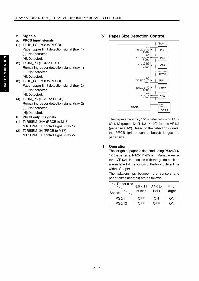
TRAY 1/2 (Di551/Di650), TRAY 3/4 (Di5510/Di7210) PAPER FEED UNIT
2-J-6
2 U
NIT
EX
PL
AN
AT
ION
2. Signalsa. PRCB input signals(1) T1UP_PS (PS2 to PRCB)
Paper upper limit detection signal (tray 1)[L]: Not detected.[H]: Detected.
(2) T1RM_PS (PS4 to PRCB)Remaining paper detection signal (tray 1)[L]: Not detected.[H]: Detected.
(3) T2UP_PS (PS8 to PRCB)Paper upper limit detection signal (tray 2)[L]: Not detected.[H]: Detected.
(4) T2RM_PS (PS10 to PRCB)Remaining paper detection signal (tray 2)[L]: Not detected.[H]: Detected.
b. PRCB output signals(1) T1RISEM_24V (PRCB to M16)
M16 ON/OFF control signal (tray 1)(2) T2RISEM_24 (PRCB to M17)
M17 ON/OFF control signal (tray 2)
[5] Paper Size Detection Control
The paper size in tray 1/2 is detected using PS5/6/11/12 (paper size/1-1/2-1/1-2/2-2), and VR1/2(paper size/1/2). Based on the detection signals,the PRCB (printer control board) judges thepaper size.
1. OperationThe length of paper is detected using PS5/6/11/12 (paper size/1-1/2-1/1-2/2-2) . Variable resis-tors (VR1/2) interlocked with the guide positionare installed at the bottom of the tray to detect thewidth of paper.The relationships between the sensors andpaper sizes (lengths) are as follows:
Paper size
Sensor
8.5 x 11 or less
A4R to B5R
F4 or larger
PS5/11 OFF ON ON
PS6/12 OFF OFF ON
VR1
PRCBDCPS
5V2S.GND
3.3V2T1SIZE_VR
AGND
PS65V3
T1SIZE_L_PSSGND
PS55V3
T1SIZE_S_PSSGND
VR23.3V2
T2SIZE_VRAGND
PS125V3
T2SIZE_L_PSSGND
PS115V3
T2SIZE_S_PSSGND
Tray 1
Tray 2
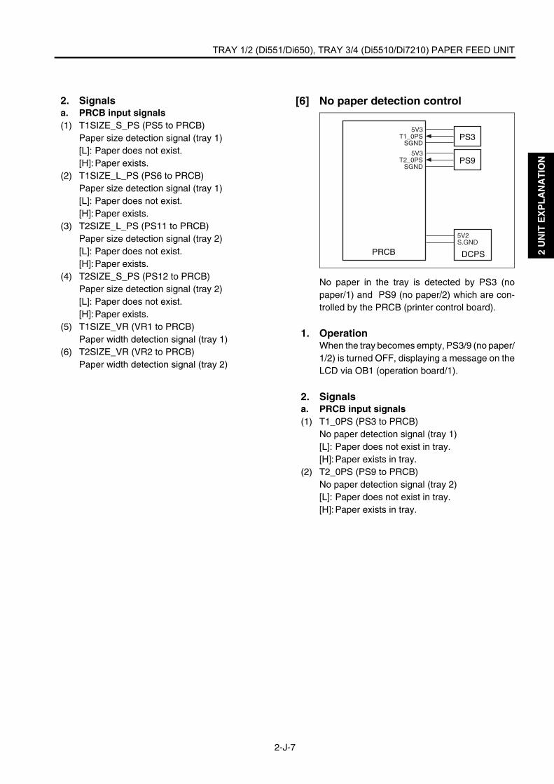
TRAY 1/2 (Di551/Di650), TRAY 3/4 (Di5510/Di7210) PAPER FEED UNIT
2-J-7
2 U
NIT
EX
PL
AN
AT
ION
2. Signalsa. PRCB input signals(1) T1SIZE_S_PS (PS5 to PRCB)
Paper size detection signal (tray 1)[L]: Paper does not exist.[H]: Paper exists.
(2) T1SIZE_L_PS (PS6 to PRCB)Paper size detection signal (tray 1)[L]: Paper does not exist.[H]: Paper exists.
(3) T2SIZE_L_PS (PS11 to PRCB)Paper size detection signal (tray 2)[L]: Paper does not exist.[H]: Paper exists.
(4) T2SIZE_S_PS (PS12 to PRCB)Paper size detection signal (tray 2)[L]: Paper does not exist.[H]: Paper exists.
(5) T1SIZE_VR (VR1 to PRCB)Paper width detection signal (tray 1)
(6) T2SIZE_VR (VR2 to PRCB)Paper width detection signal (tray 2)
[6] No paper detection control
No paper in the tray is detected by PS3 (nopaper/1) and PS9 (no paper/2) which are con-trolled by the PRCB (printer control board).
1. OperationWhen the tray becomes empty, PS3/9 (no paper/1/2) is turned OFF, displaying a message on theLCD via OB1 (operation board/1).
2. Signals a. PRCB input signals(1) T1_0PS (PS3 to PRCB)
No paper detection signal (tray 1)[L]: Paper does not exist in tray.[H]: Paper exists in tray.
(2) T2_0PS (PS9 to PRCB)No paper detection signal (tray 2)[L]: Paper does not exist in tray.[H]: Paper exists in tray.
PRCB DCPS
5V2S.GND
PS95V3
T2_0PSSGND
PS35V3
T1_0PSSGND

TRAY 1/2 PAPER FEED UNIT (Di5510/Di7210)
2-J-8
J U
NIT
EX
PL
AN
AT
ION
TRAY 1/2 PAPER FEED UNIT (Di5510/Di7210)
[1] Composition
Caution: Trays 1/2 have the same mechanism.
[2] Mechanisms *1 Paper lift-upa) Hoisting of up/down plate
Paper feed trays are driven by wires. When apaper tray is loaded, the tray up drive motor/1(M16)/2(M17) rotates to wind the wiresaround the drive pulleys and consequentlythe up/down plate in the tray moves up. Whenthe tray upper limit PS/1(PS2)/2(PS8) detectsthe actuator of the roller that has been movedup by paper, the tray up drive motor/1(M16)/2 (M17) stops.
7272ma2004
Double feed prevention rollerPaper feed rollerFeed roller
Side guide
Horizontal conveyance section
Horizontal conveyance PS/L (PS5)
Tray 1 Feed roller
Horizontal conveyance roller/L
Pre-registration rollerPaper feed roller
Feed roller
Double feed prevention roller
Tray up drive motor /1 (M16)
Horizontal conveyance roller/R
Horizontal conveyance PS/R (PS6)
Pre - registration roller
Paper feed roller
Double feed prevention roller
Tray up drive motor /2(M17)Tray 2
Mechanism Method
Paper lift-up *1 Up: Driven by wiresDown: Falls down by its own weight
Tray loading Front loading
Double feed preven-tion
Torque limiter
1st paper feed Paper feed roller
No paper detection Photosensor + Actuator
1st paper feed paper loop mechanism*2
Photosensor + Actuator+ clutch
Horizontal convey-ance (Tray 1)
Horizontal conveyance roller /L, /R

TRAY 1/2 PAPER FEED UNIT (Di5510/Di7210)
2-J-9
2 U
NIT
EX
PL
AN
AT
ION
b) Lowering of trayWhen the paper feed tray is pulled out, thecoupling shaft of the tray is disengaged fromthe coupling gear of the tray up drive motor onthe main body side, allowing the up/downplate in the tray to fall down by its own weight.
*2 First paper feed paper loop mechanismWhen paper feed starts, paper is fed to the pre-registration roller by the feed roller and paperfeed rollers. The fed out paper operates theactuator of the paper feed PS/1 (PS1), the paperfeed PS/2 (PS7) turning it ON. The feed andpaper feed rollers remain ON for a specified timeafter the actuation of the paper feed PS/1 (PS1)and PS/2 (PS7) causing a paper loop to formagainst the pre-registration rollers which are notturning. In this way paper skew is corrected.
7272ma2005
Coupling gear
Coupling [Tray side]
[Main body side]
7272ma2006
Feed roller
Pre-registration roller
Paper feed roller
Paper feed PS/1(PS1), /2 (PS2)

TRAY 1/2 PAPER FEED UNIT (Di5510/Di7210)
2-J-10
2 U
NIT
EX
PL
AN
AT
ION
[3] First Paper Feed Control
The 1st paper feed from tray 1/2 takes place asthe result of the transmission of the drive forcefrom M1 (paper feed) to each paper feed roller byMC3/5 (paper feed MC/1/2) and MC4/6(pre-reg-istration MC/1/2). The feed roller picks up paperusing its own weight.The above operations are controlled by thePRCB (printer control board). Related signalsare PS1/7 (paper feed/1/2) and PS25/26 (verti-cal conveyance/1/2) issued from the vertical con-veyance section.
1. Operationa. Operation of the MC3/5 (paper feed MC/1/2)(1) Start timing of printing of the first copy
MC3/5 (paper feed MC/1/2) turns ON at the tim-ing that is determined by the P counter fromwhen copying starts, and turns OFF after a lapseof the specified time from PS1/7 (paper feed/1/7)turning OFF. Thus, paper skew is corrected byforming the loop before pre-registration roller.
(2) Start timing of printing of the second copyWhen the preceding paper turns OFF PS1/7.
(3) OFF timingWhen PS1/7 is turned ON.
b. Operation of the MC4/6 (pre-registrationMC1/2)
(1) ON timingAfter a specified time from MC3/5 (paper feedMC/1/2) turning ON.
(2) OFF timingWhen PS1/7 (paper feed/1/2) is turned OFF.
7272ma2007
PS7
MC6
MC5
PS1
MC4
MC3
PRCB
DCPS
24V1P.GND
5V2S.GND
24V2P.GND
FEEDM_CONTFEEDM_CLKFEEDM_F/EFEEDM_EM5VP.GND
MC24V_1T1FEED_DRV
MC24V_1T1PREMC_DRV
MC24V_1C
MC24_1T2PREMC_DRV
5V3T1PRE_PS
SGND
5V3T2PRE_PS
SGND
MS2
MS1
M1
Tray 1
Tray 2

TRAY 1/2 PAPER FEED UNIT (Di5510/Di7210)
2-J-11
2 U
NIT
EX
PL
AN
AT
ION
2. Signalsa. PRCB input signals(1) T1PRE_PS (PS1 to PRCB)
Paper passage detection signal (tray 1)[L]: Detected.[H]: Not detected.
(2) T2PRE_PS (PS7 to PRCB)Paper passage detection signal (tray 2)[L]: Detected.[H]: Not detected.
b. PRCB output signals(1) T1FEED_DRV (PRCB to MC3)
MC3 drive control signal (tray 1)[L]: MC3 ON[H]: MC3 OFF
(2) T1PREMC_DRV (PRCB to MC4)MC4 drive control signal (tray 1)[L]: MC4 ON[H]: MC4 OFF
(3) T2FEED_DRV (PRCB to MC5)MC5 drive control signal (tray 2)[L]: MC5 ON[H]: MC5 OFF
(4) T2PREMC_DRV (PRCB to MC6)MC6 drive control signal (tray 2)[L]: MC6 ON[H]: MC6 OFF

TRAY 1/2 PAPER FEED UNIT (Di5510/Di7210)
2-J-12
2 U
NIT
EX
PL
AN
AT
ION
[4] Horizontal Conveyance Control (Tray 1)
The horizontal conveyance from Tray 1 is con-ducted by transmitting the drive force of M1(paper feed) to the horizontal conveyance roller/L and horizontal conveyance roller /R via MC15(horizontal conveyance MC/L) and MC16 (hori-zontal conveyance MC/R).
The above operations are controlled by PRCB(printer control board). Related signals are PS1(feed /1), PS5 (horizontal conveyance /L) andPS6 (horizontal conveyance /R).
1. Operationa. Operation of MC15 (horizontal conveyance
MC/L)(1) ON timing for the first paper
When the restart of MC3 (feed MC/1) is turnedON.
(2) ON timing for the second paper After a specified time when MC1 (registrationMC) is turned ON.
(3) OFF timingAfter a specified time when PS44 (registration) isturned ON.
b. Operation of MC16 (horizontal conveyanceMC/R)
(1) ON timing for the first paperAfter a specified time when PS6 (horizontal con-veyance /R) is turned ON.
(2) ON timing for the second paper After a specified time when MC1 (registrationMC) is turned ON.
(3) OFF timingAfter a specified time when PS6 (horizontal con-veyance /R) is turned ON.
7272ma2008ADUDB
PRCB
IO DTXDIO DCLK
ADU LATCHIO UCLK
REQ1IO URXD
ACK1ERR OUT12NDM CLK
REG PS
PS445V2
2ND PSS.GND
MC1MC24V
2ND MC
DCPS
24V15V2
S.GNDP.GND
-5V1
5V224V1
S.GND
5V3HFPS_LS.GND
FEEDM_CONTFEEDM_CLKFEEDM_F/EFEEDM_EM5VP.GND
24V3
HFMC_L
24V3
HFMC_R
M1
P.GND
24V2
PS5
5V3HFPS_RS.GND
PS6
MC15
MC16
MS1
MS2

TRAY 1/2 PAPER FEED UNIT (Di5510/Di7210)
2-J-13
2 U
NIT
EX
PL
AN
AT
ION
2. Signala. PRCB input signal(1) HFPS_L (PS5 to PRCB)
Paper passage detection signal[L]: Detected.[H]: Not detected
(2) HFPS_R (PS6 to PRCB)Paper passage detection signal[L]: Detected.[H]: Not detected
b. PRCB output signal(1) HFMC_L (PRCB to MC15)
MC15 drive control signal[L]: MC15 ON[H]: MC15 OFF
(2) HFMC_R (PRCB to MC16)MC16 drive control signal[L]: MC16 ON[H]: MC16 OFF

TRAY 1/2 PAPER FEED UNIT (Di5510/Di7210)
2-J-14
2 U
NIT
EX
PL
AN
AT
ION
[5] Paper Up Drive Control
Paper stacked in the tray is pushed up by trans-mitting the drive force of M16/17 (tray up drive/1/2) to the up/down plate in the tray via drivewires. M16/17 are controlled by the PRCB(printer control board). Related signals are PS2/8 (tray upper limit/1/2) and PS4/10 (remainingpaper/1/2).
1. Operationa. Paper up drive control
When tray 1/2 is loaded, M16/17 (tray up drive/1/2) turns ON to lift the up/down plate in the tray.When PS2/8 (tray upper limit/1/2) detects theupper limit of paper as the paper up/down platein the tray goes up, it turns ON and consequentlyM16/17 goes OFF, causing the tray to stop goingup. When PS2/8 turns OFF after paper is fed,M16/17 goes ON again to move the paper up/down plate upward. The up/down plate in the trayis lowered mechanically by its own weight.
b. Paper up drive timing(1) ON timing
M16/17 (tray up drive/1/2) is turned ON whenloading of a tray is detected. (by shorting wires atboth ends of the drawer connector)
(2) OFF timingOne of M16/17 (tray up drive/1/2) is turned OFFwhen PS2/8 (tray upper limit/1/2) is turned ON.
c. Remaining Paper Detection ControlThe level of paper remaining in each tray isdetected according to the time that M16/17 (trayup drive/1/2) requires to lift up the up/down platewhen the tray is set. This lift-up time (operationtime of M16/17) is saved in the PRCB (printercontrol board) . After this, the remaining paperis detected using the paper feed counter. Thedetected remaining paper level is displayed onthe operation panel in five steps. PS4/10(remaining paper/1/2) are used to detect theremaining paper level when it lowers below about10%.
7272ma2009
PS2
PS4
PRCB
DCPS
24V1P.GND
5V2S.GND
T1RISEM_24VT1RISEM_D
T2RISEM_24T2RISEM_D
5V3TIUP_PS
SGND
5V3TIRM_PS
SGND
PS8
PS10
5V3TIUP_PS
SGND
5V3TIRM_PS
SGND
M16
M17
Tray 1
Tray 2

TRAY 1/2 PAPER FEED UNIT (Di5510/Di7210)
2-J-15
2 U
NIT
EX
PL
AN
AT
ION
2. Signalsa. PRCB input signals(1) T1UP_PS (PS2 to PRCB)
Paper upper limit detection signal (tray 1)[L]: Not detected.[H]: Detected.
(2) T1RM_PS (PS4 to PRCB)Remaining paper detection signal (tray 1)[L]: Not detected.[H]: Detected.
(3) T1UP_PS (PS8 to PRCB)Paper upper limit detection signal (tray 2)[L]: Not detected.[H]: Detected.
(4) T1RM_PS (PS10 to PRCB)Remaining paper detection signal (tray 2)[L]: Not detected.[H]: Detected.
b. PRCB output signals(1) T1RISEM_24V (PRCB to M16)
M16 ON/OFF control signal (tray 1)(2) T2RISEM_24 (PRCB to M17)
M17 ON/OFF control signal (tray 2)
[6] No paper detection control
No paper in the tray is detected by PS3 (no paper/1) and PS9 (no paper /2), and which is controlledby the PRCB (printer control board).
1. OperationWhen the tray becomes empty, PS3/9 (no paper/1/2) is turned OFF, displaying a message on theLCD via OB1 (operation board/1).
2. Signals a. PRCB input signals(1) T1_0PS (PS3 to PRCB)
No paper detection signal (tray 1)[L]: Paper does not exist in tray.[H]: Paper exists in tray.
(2) T2_0PS (PS9 to PRCB)No paper detection signal (tray 2)[L]: Paper does not exist in tray.[H]:Paper exists in tray.
7272ma2010
PRCB DCPS
5V2S.GND
PS95V3
T2_0PSSGND
PS35V3
T1_0PSSGND

2 U
NIT
EX
PL
AN
AT
ION
Blank page

TRAY 3 PAPER FEED UNIT (Di551/Di650)
2-K-1
2 U
NIT
EX
PL
AN
AT
ION
TRAY 3 PAPER FEED UNIT (Di551/Di650)
[1] Composition
[2] Mechanisms *1 Paper lift-upa) Hoisting of up/down plate
Paper feed tray is driven by wires. When thepaper tray is loaded, the tray up drive motor 3(M18) rotates to wind the wires around thedrive pulleys and consequently the up/downplate in the tray moves up. When the trayupper limit PS/3 (PS14) detects the actuatorof the roller that has been moved up by paper,the tray up drive motor 3 (M18) stops.
End stopper
Drive pulley (for wire C/D)Tray up drive motor/3 (M18) Feed roller
Paper feed roller
Double feed prevention roller
Side guideSide guide
Drive pulley (for wire A/B)
Paper size PS/2-3(PS18)
Paper size VR/3(VR3)
Paper size PS/1-3(PS17)
Mechanism Method
Paper lift-up *1 Up: Driven by wiresDown: Falls down by its own weight
Tray loading Front loading
Double feed pre-vention
Torque limiter
1st paper feed Paper feed roller
No paper detec-tion
Photosensor + Actuator
Paper size detec-tion *2(Universal)
Width: VRLength: Photosensor + Actuators (two)
1st paper feedpaper loop mech-anism*3
Photosensor + Actuator+ Magnetic clutch

TRAY 3 PAPER FEED UNIT (Di551/Di650)
2-K-2
2 U
NIT
EX
PL
AN
AT
ION
b) Lowering of trayWhen the paper feed tray is pulled out, thecoupling shaft of the tray is disengaged fromthe coupling gear of the tray up drive motor onthe main body side, allowing the up/downplate in the tray to fall down by its own weight.
*2 Paper size detectionLength: When paper pushes the paper size
detection actuator, the paper size PS/2-3/ (PS18) and the paper size PS/1-3(PS17) turns ON. Thus, the paper size isautomatically determined according tothe combination of the ON/OFF states ofthis PS.
Width: When the side guides of the tray are slid,the rack gear of the side guide (front)turns the paper size VR3 gear. Thus, thepaper size is automatically determinedaccording to the change in the resis-tance value of the VR.
*3 First paper feed paper loop mechanismWhen paper feed starts, paper is fed to the pre-registration roller by the feed roller and paperfeed rollers. The fed out paper operates theactuator of the paper feed PS/3 (PS13), turningit ON. The feed and paper feed rollers remainON for a specified time after the actuation of thepaper feed PS/3 (PS13) causing a paper loop toform against the pre-registration rollers whichare not turning. In this way paper skew is cor-rected.
Coupling gear
[Main body side]
Coupler[Tray side]
Paper size VR gear
Rack gear
Side guide (front)
Feed roller
Pre-registration roller
Paper feed roller
Paper feed PS/3 (PS13)

TRAY 3 PAPER FEED UNIT (Di551/Di650)
2-K-3
2 U
NIT
EX
PL
AN
AT
ION
[3] First Paper Feed Control
The 1st paper feed from tray 3 takes place as theresult of the transmission of the drive force fromM1 (paper feed) to each paper feed roller by MC7(paper feed MC/3) and MC8 (pre-registrationMC/3). The feed roller picks up paper using itsown weight.The above operations are controlled by thePRCB (printer control board). Related signalsare PS13 (paper feed/3) and PS27 (vertical con-veyance/3) issued from the vertical conveyancesection.
1. Operationa. Operation of the MC7 (paper feed MC/3)(1) Start timing of printing of the first copy
MC7 (paper feed MC/3) turns ON at the timingthat is determined by the P counter from whencopying starts, and turns OFF after a lapse of thespecified time from PS13 (paper feed/3) turningOFF. Thus, paper skew is corrected by formingthe loop before pre-registration roller.
(2) Start timing of printing of the second copyWhen the preceding paper turns OFF PS13.
(3) OFF timingWhen PS13 is turned ON.
b. Operating of the MC8 (pre-registration MC/3) (1) ON timing
After a specified time from the MC7 (paper feedMC/5).
(2) OFF timingWhen PS13 (paper feed/3) is turned OFF.
PS13
MC8
MC7
PRCB
DCPS
24V1P.GND
5V2S.GND
24V2P.GND
FEEDM_CONTFEEDM_CLKFEEDM_F/EFEEDM_EM5VP.GND
MC24V_1T3FEED_DRV
MC24V_1T3PREMC_DRV
5V3T3PREM_PS
SGND
MS2
MS1
M1
Tray 3

TRAY 3 PAPER FEED UNIT (Di551/Di650)
2-K-4
2 U
NIT
EX
PL
AN
AT
ION
2. Signalsa. PRCB input signals(1) T3PREM_PS (PS13 to PRCB)
Paper passage detection signal (tray 3)[L]: Detected.[H]: Not detected.
b. PRCB output signals(1) T3FEED_DRV (PRCB to MC7)
MC7 drive control signal (tray 3)[L]: MC7 ON[H]: MC7 OFF
(2) T3PREM_PS (PRCB to MC8)MC8 drive control signal (tray 3)[L]: MC8 ON[H]: MC8 OFF

TRAY 3 PAPER FEED UNIT (Di551/Di650)
2-K-5
2 U
NIT
EX
PL
AN
AT
ION
[4] Paper Up Drive Control
Paper stacked in the tray is pushed up by trans-mitting the drive force of M18 (tray up drive/3) tothe up/down plate in the tray via drive wires. M18is controlled by the PRCB (printer control board).Related signals are PS14 (tray upper limit/3) andPS16 (remaining paper/3).
1. Operationa. Paper up drive control
When tray 3 is loaded, M18 (tray up drive/3) turnsON to lift the up/down plate in the tray. WhenPS14 (tray upper limit/3) detects the upper limitof paper as the paper up/down plate in the traygoes up, it turns ON and consequently M18 goesOFF, causing the tray to stop going up. WhenPS14 turns OFF after paper is fed, M18 goes ONagain to move the paper up/down plate upward.The up/down plate in the tray is lowered mechan-ically by its own weight.
b. Paper up drive timing(1) ON timing
M18 (tray up drive /3) is turned ON when loadingof a tray is detected. (by shorting wires at bothends of the drawer connector)
(2) OFF timingM18 (tray up drive/3) is turned OFF when PS14(tray upper limit/3) is turned ON.
c. Remaining Paper Detection ControlThe level of paper remaining in the tray isdetected according to the time that M18 (tray updrive/3) requires to lift up the up/down plate whenthe tray is set. This lift-up time (operation time ofM18) is saved in the PRCB (printer controlboard). After this, the remaining paper isdetected using the paper feed counter. Thedetected remaining paper level is displayed onthe operation panel in five steps. PS16 (remain-ing paper/3) is used to detect the remainingpaper level when it lowers below about 10%.
PS14
PS16
PRCB
DCPS
24V1P.GND
5V2S.GND
T3RISEM_24T3RISEM_D
5V3TIUP_PS
SGND
5V3TIRM_PS
SGND
M18
Tray 3
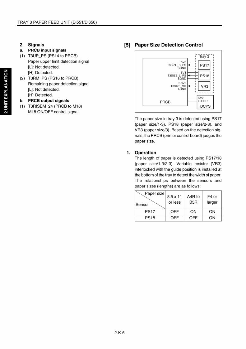
TRAY 3 PAPER FEED UNIT (Di551/Di650)
2-K-6
2 U
NIT
EX
PL
AN
AT
ION
2. Signalsa. PRCB input signals(1) T3UP_PS (PS14 to PRCB)
Paper upper limit detection signal[L]: Not detected.[H]: Detected.
(2) T3RM_PS (PS16 to PRCB)Remaining paper detection signal[L]: Not detected.[H]: Detected.
b. PRCB output signals(1) T3RISEM_24 (PRCB to M18)
M18 ON/OFF control signal
[5] Paper Size Detection Control
The paper size in tray 3 is detected using PS17(paper size/1-3), PS18 (paper size/2-3), andVR3 (paper size/3). Based on the detection sig-nals, the PRCB (printer control board) judges thepaper size.
1. OperationThe length of paper is detected using PS17/18(paper size/1-3/2-3). Variable resistor (VR3)interlocked with the guide position is installed atthe bottom of the tray to detect the width of paper.The relationships between the sensors andpaper sizes (lengths) are as follows:
Paper size
Sensor
8.5 x 11 or less
A4R to B5R
F4 or larger
PS17 OFF ON ON
PS18 OFF OFF ON
PRCBDCPS
5V2S.GND
3.3V2T3SIZE_VR
AGND
5V3T3SIZE_L_PS
SGND
5V3T3SIZE_S_PS
SGND
VR3
PS18
PS17
Tray 3

TRAY 3 PAPER FEED UNIT (Di551/Di650)
2-K-7
2 U
NIT
EX
PL
AN
AT
ION
2. Signalsa. PRCB input signals(1) T3SIZE_S_PS (PS17 to PRCB)
Paper size detection signal [L]: Paper does not exist.[H]: Paper exists.
(2) T3SIZE_L_PS (PS18 to PRCB)Paper size detection signal[L]: Paper does not exist.[H]: Paper exists.
(3) T3SIZE_VR (VR3 to PRCB)Paper width detection signal
[6] No paper detection control
No paper in the tray is detected by PS15 (nopaper/3), and which is controlled by the PRCB(printer control board).
1. OperationWhen the tray becomes empty, PS15 (no paper/3) is turned OFF, displaying a message on theLCD via OB1 (operation board/1).
2. Signals a. PRCB input signals(1) PS15 (PS15 to PRCB)
No paper detection signal[L]: Paper does not exist in tray.[H]: Paper exists in tray.
PRCB DCPS
5V2S.GND
PS155V3
T3_0PSSGND

2 U
NIT
EX
PL
AN
AT
ION
Blank page

BY-PASS TRAY
2-L-1
2 U
NIT
EX
PL
AN
AT
ION
BY-PASS TRAY
[1] Composition
[2] Mechanisms *1 Paper lift-upThe up/down motor/BP (M20) drives the paperup/down plate via gears. Paper is automaticallypushed up to the paper feed position, when theprint start button is pressed. When paper isremoved or exhausted M20 will drive down theup/down plate.
Up/down motor/BP (M20)
By-pass paper feed roller
By-pass double feed prevention roller
By-pass feed roller
Loop roller
By-pass tray
Mechanism Method
First paper feed By-pass feed roller
Paper lift-up *1 Paper up/down plateUp/down motor/BP (M20) + Upper/lower limit detection sensor
Double feed preven-tion
Torque limiter
No paper detection Photo sensor + Actuator
Paper size detection *2
Width: VRLength: Photo sensor + Actuators (two)
Paper up/down plate
Up/down motor/BP (M20)

BY-PASS TRAY
2-L-2
2 U
NIT
EX
PL
AN
AT
ION
*2 Paper size detectionThe paper size is automatically detected by thefollowing three sensors:• Lateral: Paper size detection VR/BP (VR5)• Longitudinal: Paper size PS/1, 2-BP (PS31/
32)
[3] First Paper Feed Control
The first paper feed from the by-pass tray takesplace as the result of the transmission of the driveforce from M6 (loop roller) to the paper feedroller. M6 is controlled by PRCB (printer controlboard). The related signal is PS36 (loop).
1. Operation(1) When printing of the first copy starts
M6 (loop) is turned ON at the timing that is deter-mined by the P counter (that starts when printingstarts), thus starting feed of paper.M6 is stopped temporarily after lapse of a spec-ified time from turning ON of PS44 (registration)by the leading edge of paper, a loop is formed byregistration rollers, and the paper is fed to thetransfer unit.
(2) When printing of the second or subsequent copyAfter lapse of the specified time from turning OFFof PS44 (registration) by the trailing edge of thepreceding paper.
2. Signalsa. PRCB input signals(1) LOOP_PS (PS36 to PRCB)
Paper passage detection signal[L]: Paper does not exist.[H]: Paper exist.
(2) 2ND_PS (PS44 to PRCB)Second paper feed reference timing detectionsignal[L]: Paper exists.[H]: Paper does not exist.
Paper size VR/BP (VR5)
Paper size PS/2-BP (PS32)
Paper size PS/1-BP (PS31)
By-pass tray
PRCB
PS36
PS44
24V24V
A/A
B/B
24V2P.GND
5V2S.GND
M6
5V3LOOP_PS
S.GND
5V22ND_PS
S.GND
Second paper feed unit

BY-PASS TRAY
2-L-3
2 U
NIT
EX
PL
AN
AT
ION
b. PRCB output signals(1) A and /A (PRCB to M6)
A-phase drive control pulse signal for M6(2) B and /B (PRCB to M6)
B-phase drive control pulse signal for M6
[4] Paper Up/Down Control
Paper in the by-pass tray is pushed up/down byM20 (up/down motor/BP). M20 is controlled byPRCB (printer control board). Related signalsare PS34 (tray upper limit /BP) and PS35 (traylower limit /BP).
1. Operationa. Paper up/down control
M20 (up/down motor/BP) is turned ON to pushup paper. When PS34 (tray upper limit/BP)detects the paper upper limit and turns ON, M20turns OFF to stop pushing up paper. When paperis fed and consequently PS34 turns OFF, M20turns ON again, maintaining the upper limit posi-tion of paper.
b. Paper up timing(1) ON timing
At start of copying(2) OFF timing
M20 (up/down motor/BP) is turned OFF whenPS34 (tray upper limit /BP) is turned ON.
c. Paper down timing(1) ON timing
When there is no paper or a paper jam occurs.(2) OFF timing
M20 (up/down motor/BP) is turned OFF whenPS35 (tray lower limit/BP) is turned ON.
PS34
PRCBDCPS
5V2S.GND
BPUDM_ABPUDM_B
5V3BPUP_PSSGND
PS355V3BPDN_PSSGND
M20

BY-PASS TRAY
2-L-4
2 U
NIT
EX
PL
AN
AT
ION
2. Signalsa. PRCB input signals(1) BPUP_PS (PS34 to PRCB)
Paper upper limit position detection signal (by-pass tray)[L]: Not detected.[H]: Detected.
(2) BPDN_PS (PS35 to PRCB)Paper lower limit position detection signal (by-pass tray)[L]: Not detected.[H]: Detected.
b. PRCB output signal(1) BPUDM_A, B (PRCB to M20)
M20 drive control signal
[5] Paper Size Detection Control
The size of paper in the by-pass tray is detectedby PS31 (paper size/1-BP), PS32 (paper size/2-BP), and VR5 (paper size/BP). Based on thedetection signals, PRCB (printer control board)judges the paper size.
1. OperationThe length of paper is detected by PS31 (papersize/1-BP) and PS32 (paper size/2-BP). The by-pass tray is provided with a variable resistor(VR5) interlocked with the guide position to judgethe paper width according to the change in theresistance value.The relationships between the sensors andpaper sizes (lengths) are as follows:
2. Signalsa. PRCB input signals(1) BPSIZE_S_PS (PS31 to PRCB)
Paper size detection signal[L]: Paper does not exist.[H]: Paper exists.
(2) BPSIZE_L_PS (PS32 to PRCB)Paper size detection signal[L]: Paper does not exist.[H]: Paper exists.
(3) BPSIZE_VR (VR5 to PRCB)Paper width detection signal
Paper sizeSensor
8.5 x 11 or less
A4R to B5R
F4 or larger
PS31 OFF ON ON
PS32 OFF OFF ON
VR5
PRCB
DCPS
5V2S.GND
5VABPSIZE_VR
PS325V3
BPSIZE_L_PSSGND
PS315V3
BPSIZE_S_PSSGND

BY-PASS TRAY
2-L-5
2 U
NIT
EX
PL
AN
AT
ION
[6] No paper detection control
No paper in the tray is detected by PS33 (nopaper/BP) which is controlled by PRCB (printercontrol board).
1. OperationWhen the tray becomes empty, PS33 (no paper/BP) is turned OFF, displaying a message on theLCD via OB1 (operation board/1).
2. Signal a. Input signal(1) BP_0PS (PS33 to PRCB)
No paper detection signal [L]: Paper does not exist.[H]: Paper exists.
PRCBDCPS
5V2S.GND PS33
5V3BP_OPS
SGND

2 U
NIT
EX
PL
AN
AT
ION
Blank page
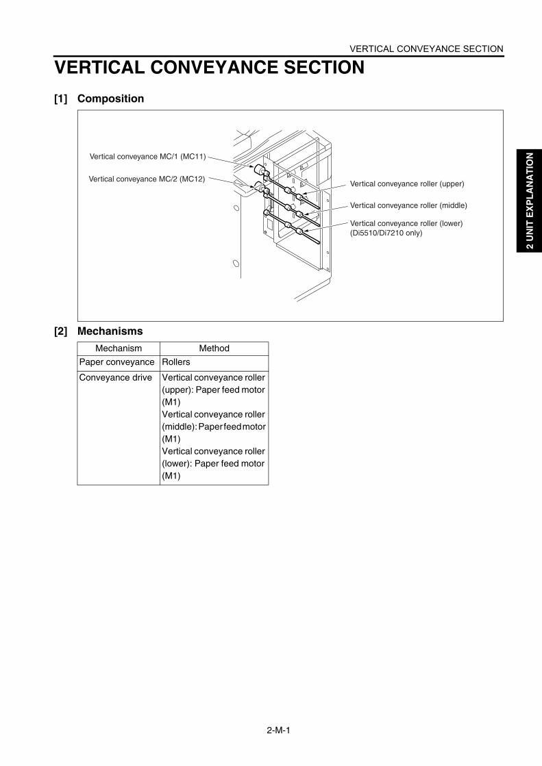
VERTICAL CONVEYANCE SECTION
2-M-1
2 U
NIT
EX
PL
AN
AT
ION
VERTICAL CONVEYANCE SECTION
[1] Composition
[2] Mechanisms
Vertical conveyance MC/1 (MC11)
Vertical conveyance MC/2 (MC12)Vertical conveyance roller (upper)
Vertical conveyance roller (middle)
Vertical conveyance roller (lower)(Di5510/Di7210 only)
Mechanism Method
Paper conveyance Rollers
Conveyance drive Vertical conveyance roller (upper): Paper feed motor (M1)Vertical conveyance roller (middle): Paper feed motor (M1)Vertical conveyance roller (lower): Paper feed motor (M1)

VERTICAL CONVEYANCE SECTION
2-M-2
2 U
NIT
EX
PL
AN
AT
ION
[3] Vertical Conveyance Control
In the vertical conveyance section, paper is fedvertically by transmitting the drive force of M1(paper feed) to the vertical conveyance roller(upper) and vertical conveyance roller (middle)via MC11 (vertical conveyance MC/1) and MC12(vertical conveyance MC/2). And, the verticalconveyance roller (lower) is driven by the verticalconveyance roller (middle) via the timing belt.The above parts are controlled by PRCB (printercontrol board). Related signals are PS25 toPS28 (vertical conveyance / 1 to 3), PS29 (ver-tical conveyance door open/close) and PS12(vertical conveyance door open/close /U).
1. OperationPaper fed from tray 1 (Di551/Di650) or tray 1 or2 (Di5510/Di7210) is then fed to the secondpaper feed unit directly without passing throughvertical conveyance rollers. When paper is fedfrom tray 2 or 3 (Di551/Di650) or tray 3 or 4(Di5510/Di7210), PS26 (vertical conveyance/2)is used to feed paper to the standby position.When PS26 is turned OFF by the precedingpaper, MC11 and MC12 (vertical conveyanceMC/1 and MC/2) are turned ON and the paperfed from tray 2 or 3 (Di551/Di650) or tray 3 or 4(Di5510/Di7210) is fed to the standby position(where PS26 was turned ON) by the drive forceof M1 (paper feed). MC11 and MC12 are turnedON after lapse of the specified time from restartof registration of the preceding paper to rotate all
vertical conveyance rollers, thus feeding paper tothe second paper unit.The paper feed standby position for tray 4 is setto the position where the PS28 (vertical convey-ance /4) is turned ON. (Di5510/Di7210)
2. Signalsa. PRCB input signals(1) T1PASS_PS (PS25 to PRCB)
Paper passage detection signal (for tray 1)[L]: Not detected.[H]: Detected.
(2) T2PASS_PS (PS26 to PRCB)Paper passage detection signal (for tray 2)[L]: Not detected.[H]: Detected.
(3) T3PASS_PS (PS27 to PRCB)Paper passage detection signal (for tray 3)[L]: Not detected.[H]: Detected.
(4) T4PASS_PS (PS28 to PRCB)Paper passage detection signal (for tray 4)[L]: Not detected.[H]: Detected.
(5) VF_DOOR_PS (PS29 to PRCB)Vertical conveyance section open/close detec-tion signal [L]: Open[H]: Closed
(6) VF_DRT_PS (PS12 to PRCB)Vertical conveyance section open/close detec-tion signal[L]: Open[H]: Closed
b. PRCB output signals(1) VFMC1_DRV (PRCB to MC11)
MC11 drive control signal[L]: MC11 ON[H]: MC11 OFF
(2) VFMC2_DRV (PRCB to MC12)MC12 drive control signal[L]: MC12 ON[H]: MC12 OFF
7272ma2011
PS28
PS27
PS26
PS25
PS29
MC12
MC11
PRCB
DCPS
24V1P.GND
5V2S.GND
24V2P.GND
FEEDM_CONTFEEDM_CLKFEEDM_F/RFEEDM_EM5VP.GND
MC24V_2VFMC1_DRV
MC24V_2VFMC2_DRV
5V3VF_DOOR_PS
S.GND
PS125V3
VF_DRT_PSS.GND
5V3T3PASS_PS
S.GND
5V3T2PASS_PS
S.GND
5V3T1PASS_PS
S.GND
5V3T4PASS_PS
S.GND
MS2
MS1
M1

ADU
2-N-1
2 U
NIT
EX
PL
AN
AT
ION
ADU
[1] Composition
7272ma2012
ADU deceleration MC (MC2)
ADU conveyance MC (MC13)ADU drive board (ADUDB)
Reverse/exit roller rotation knob Conveyance motor (M5)
TSL
Reverse gate SD (SD7)
Reverse/exit motor (M8)
Registration MC(MC1)
Registration roller rotation knob
Mis-centering PS (PS70) Paper dust cleaning brush Paper dust cleaning brush
Paper exit fan/F (FM6)
Paper exit fan/R (FM7)
Paper exit motor (M7)
Paper exit roller rotation knob
Registration roller
Pre-transfer roller
ADU pre-registration roller
ADU reverse roller
Paper exit roller
Paper exit conveyance roller
Reverse/exit gate
ADU gate
ADU conveyance roller 1
ADU conveyance roller 2
ADU conveyance roller 3
ADU conveyance roller 4Reverse/exit roller
Conveyance belt
Transfer/separation cleaning motor (M10)
Di551/Di650
Di5510/Di7210
Di5510/Di7210

ADU
2-N-2
2 U
NIT
EX
PL
AN
AT
ION
[2] Mechanisms
Mechanisms Method
Second paper feed paper loop *1 Loop roller (trays 1-3/LCT), Feed roller (by-pass tray), ADU pre-registration roller (ADU)
Image position correction *2 Image position is corrected according to the information detected by PS43 (leading edge) and PS70 (paper mis-centering).
Second paper feed auxiliary mechanism *3 Pre-transfer roller
Second paper feed paper conveyance Conveyance motor (M5) drive
Second paper feed jam removal mechanism Opening/closing of jam removal section of pre-transfer section, Registration roller rotation knob
Conveyance section paper conveyance Conveyance belts (two)
Conveyance section paper suction mechanism *4
Conveyance suction fan (FM3) + Suction duct
Reverse/exit section paper path selection *5 Reverse/exit selection gate, Reverse gate SD (SD7) drive paper is automatically guided owing to the paper guide shape.
Reverse/exit section paper conveyance Reverse/exit roller, ADU reverse roller
Reverse/exit section paper conveyance drive Reverse/exit motor (M8) drive, ADU reverse motor (M9) drive
Reverse/exit section jam removal mechanism Paper exit guide plate opening/closing, ADU bottom plate assembly opening/closing, Reverse/exit roller rotation knob
Paper exit section jam removal mechanism Paper exit roller rotation knob
Paper exit conveyance Paper exit motor (M7) drive
ADU paper feed *6 Nonstack
ADU reverse paper conveyance path selection Paper is automatically guided owing to ADU gate opera-tion and the paper guide shape.
ADU paper conveyance ADU reverse roller, ADU conveyance rollers 1 and 2
ADU pre-registration mechanism *7 ADU pre-registration roller, ADU conveyance rollers 3 and 4
Thick paper conveyance *8 Conveyance motor (M5), Paper exit motor (M7), reverse/exit motor (M8), ADU reverse motor (M9), linear velocity selection
ADU paper conveyance drive Conveyance motor (M5), reverse/exit motor (M8), ADU reverse motor (M9), loop roller motor (M6)
ADU jam removal mechanism ADU bottom plate assembly opening/closing, Exit guide plate opening/closing

ADU
2-N-3
2 U
NIT
EX
PL
AN
AT
ION
*1 Second paper feed paper loop mechanismA paper loop is formed before the registrationroller to correct mis-centering of paper duringsecond paper feed. The paper loop is formed bypushing the fed paper against the registrationroller for the prescribed time. The paper loopmechanism differs between paper feed paths.• Trays 1-3, LCT paper feed
Loop roller• By-pass tray
By-pass feed roller• ADU
ADU pre-registration roller
*2 Image position correctionA leading edge PS (PS43) and paper mis-cen-tering PS (PS70) are provided at the exit of theregistration roller, thus enhancing the positionalaccuracy of the copy image.The paper position information detected by PS43and PS70 is processed by the image processorto correct the image write position in such a man-ner that the document (scanned image) positionmatch the copy paper position.The leading edge PS (PS43) is used to correctthe write position in the sub-scanning direction,
Loop formation point
<Trays 1-3/LCT>
<By-pass tray>
<ADU>
Feed roller
Loop formation point
Registration roller
Registration roller
ADU pre-registration roller
Registration roller
Loop roller
Loop formation point
Feed roller (LCT)

ADU
2-N-4
2 U
NIT
EX
PL
AN
AT
ION
and the mis-centering PS (PS70) is used to cor-rect the write position in the main scanning direc-tion.
*3 Second paper feed auxiliary mechanismThe distance between the registration roller andthe transfer and separation corona unit is madelong to achieve the time required for correctingthe image position. To assist conveyance ofpaper between the registration roller and theimage transfer and separation corona unit, a pre-transfer roller is provided just before the transferand separation corona unit.
*4 Conveyance section paper suction mecha-nismA paper suction duct is provided in the middle ofthe conveyance section and is led to the convey-ance suction fan (FM3) installed in the ADU. Toimprove transportability of the paper that passesthrough the conveyance section, the conveyancesuction fan is used to provide suction for thepaper.
*5 Reverse/exit paper path selectionThe reverse/exit selection gate in the fixing unitdetermines whether the paper is to be ejectedstraight or reversed and ejected. The paper gateis operated by the reverse gate SD (SD7)installed in the ADU.Because paper is reversed in the reverse/exitsection in the ADU, the reverse/exit section isprovided with a reverse/exit gate to switchbetween the forward and backward paper con-veyance paths. This gate has no drive mecha-nism and it is opened by the rigidity of the paper.
a. Reverse/exit operationNormally, the reverse/exit selection gate openswhen the reverse gate SD (SD7) is turned OFF.The paper fed by the exit roller in the fixing unit isfed, through the path under the reverse/exitselection gate, to the reverse/exit section in theADU by the decurler roller. Normally, thereverse/exit gate in the reverse/exit section isclosed. This gate is opened by the rigidity of thefed paper, allowing the paper to be fed to thereverse/exit roller, ADU gate, and ADU reverseroller sequentially. Normally, the ADU gate isclosed and it has no drive mechanism; it isopened by the rigidity of paper.When the paper reverse PS (PS42) detects thetrailing edge of paper and consequently turnsOFF, the reverse/exit roller and ADU reverseroller start rotating in the opposite direction, feed-ing the paper back toward the fixing unit. How-ever, since the reverse/exit gate is closed, thepaper is fed to the main body exit roller via thepath outside this gate. Thus, the paper is ejectedwith the print side down.
Pre-transfer roller
Registration roller
Transfer and separation corona unit
Leading edge PS(PS43) (rear)
Paper mis- centering PS (PS70) (front)
Conveyance suction fan (FM3)
Suction holes
Conveyance section
Duct

ADU
2-N-5
2 U
NIT
EX
PL
AN
AT
ION
b. Straight ejectionWhen paper is ejected straight, the reverse gateSD (SD7) is turned ON to close the reverse/exitselection gate. The paper fed by the paper exitroller is fed to the paper exit roller with the printside up.
c. ADU paper conveyanceIn the two-sided copy mode, the paper finishedwith printing on the front side is fed, through thepath under the reverse/exit selection gate, intothe reverse/exit section just like the reverse/exitoperation. Then, the paper is fed to the ADU bythe reverse/exit roller and ADU reverse roller.These rollers do not rotate in the opposite direc-tion even when the paper reverse PS (PS42)detects the trailing edge of the paper, allowingthe paper to be fed until the reverse/exit PS(PS46) turns OFF.
*6 Non-stack paper feed mechanismIn the two-sided copy mode, the ADU reverseroller starts rotating in the opposite directionwhen the reverse/exit PS (PS46) detects thetrailing edge of paper and consequently it turns
Fixing roller (upper)
Fixingroller(lower)
Fixing exit PS (PS30)
Exit rollerDecurler roller
ADU reverse roller
ADU gate
Reverse/exit rollerPaper reverse PS (PS42)
Reverse/exit gate
Reverse/exitgate
Main body exit roller
Reverse/exit selection gate
Fixing roller (upper)
Fixing roller (lower)
Fixing exit PS (PS30)Exit roller
Main body exit roller
Reverse/exit selection gate
Fixing roller(upper)
Fixing roller(lower)
Reverse/exit PS(PS46)
ADU reverse roller
ADU gateReverse/exit roller
Paper reverse PS (PS42)
Reverse/exit selection gateReverse/exit gate
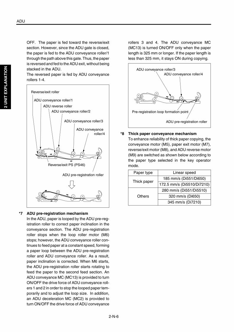
ADU
2-N-6
2 U
NIT
EX
PL
AN
AT
ION
OFF. The paper is fed toward the reverse/exitsection. However, since the ADU gate is closed,the paper is fed to the ADU conveyance roller/1through the path above this gate. Thus, the paperis reversed and fed to the ADU exit, without beingstacked in the ADU.The reversed paper is fed by ADU conveyancerollers 1-4.
*7 ADU pre-registration mechanismIn the ADU, paper is looped by the ADU pre-reg-istration roller to correct paper inclination in theconveyance section. The ADU pre-registrationroller stops when the loop roller motor (M6)stops; however, the ADU conveyance roller con-tinues to feed paper at a constant speed, forminga paper loop between the ADU pre-registrationroller and ADU conveyance roller. As a result,paper inclination is corrected. When M6 starts,the ADU pre-registration roller starts rotating tofeed the paper to the second feed section. AnADU conveyance MC (MC13) is provided to turnON/OFF the drive force of ADU conveyance roll-ers 1 and 2 in order to stop the looped paper tem-porarily and to adjust the loop size. In addition,an ADU deceleration MC (MC2) is provided toturn ON/OFF the drive force of ADU conveyance
rollers 3 and 4. The ADU conveyance MC(MC13) is turned ON/OFF only when the paperlength is 325 mm or longer. If the paper length isless than 325 mm, it stays ON during copying.
*8 Thick paper conveyance mechanismTo enhance reliability of thick paper copying, theconveyance motor (M5), paper exit motor (M7),reverse/exit motor (M8), and ADU reverse motor(M9) are switched as shown below according tothe paper type selected in the key operatormode.Reverse/exit PS (PS46)
ADU conveyance roller/1
Reverse/exit roller
ADU conveyance roller/2
ADU reverse roller
ADU conveyance roller/3
ADU conveyance roller/4
ADU pre-registration rollerPaper type Linear speed
Thick paper185 mm/s (Di551/Di650)
172.5 mm/s (Di5510/Di7210)
Others
280 mm/s (Di551/Di5510)
320 mm/s (Di650)
345 mm/s (Di7210)
ADU conveyance roller/3ADU conveyance roller/4
ADU pre-registration roller
Pre-registration loop formation point

ADU
2-N-7
2 U
NIT
EX
PL
AN
AT
ION
[3] Loop/Second Paper Feed Control
The paper fed from each tray is fed to the secondpaper feed section. The second paper feed takesplace as the result of the transmission of the driveforce from M5 (conveyance) to the second paperfeed roller via MC1 (registration). The secondpaper feed section is preceded by a loop rollerused to form a paper loop, and this conveyancesection is also used for the paper fed from theLCT. It is not used for the paper fed from the by-pass tray or ADU. The loop roller is driven by M6(loop roller). The above parts are controlled byPRCB (printer control board) via ADUDB (ADUdrive board). M6 is driven by PRCB directly.Related signals are PS36 (loop), PS43 (leadingedge), PS44 (registration), and PS50 (ADU pre-registration).
1. Operationa. Loop control
After a lapse of the specified time from turningON of PS44 (registration) by the paper fed fromeach tray or the ADU at a high speed, M6 (looproller) is turned OFF to form a paper loop in theregistration section.
b. Second paper feed controlAfter formation of a paper loop under loop con-trol, MC1 (registration) is turned ON to transmitthe drive force of M5 (conveyance) to the secondpaper feed roller, starting the second paper feed.
c. Image position correction controlMis-centering of the paper fed from each tray isdetected by PS70 (paper mis-centering) and thepaper leading edge timing is detected by PS43(leading edge) and they are corrected at the timeof image write.
ADUDB
M5
M6
PS50
+5VPGND
START/STOPCLK
CW/CCWLDH/L
PGND+24V
24V24V
A/AB/B
5V2ADUEXT PS
S.GND
PS70
DEF VIDEOGMD5V2-5V
GNDDEF SI
DEF CLKDEF LED
24V1
PRCB
IO DTXDIO DCLK
ADU LATCHIO UCLK
REQ1IO URXD
ACK1ERR OUT12NDM CLK
REG PS
PS445V2
2ND PSS.GND
PS43
MC1
PS36
5V2EDGE PS
S.GND
MC24V
2ND MC
5V3LOOP PS
S.GND
DCPS
24V15V2
S.GNDP.GND
-5V1
5V224V1
S.GND

ADU
2-N-8
2 U
NIT
EX
PL
AN
AT
ION
A contact image sensor is used as PS70 (papermis-centering). The paper edge position isdetected by paper mis-centering sensors. Basedon the edge position information, the image writeposition is shifted to correct mis-centering andleading edge timing at the time of image write.PS70 operates after a lapse of the specified timefrom turning ON of PS43 (leading edge).
2. Signalsa. Input signals(1) LOOP_PS (P36 to PRCB)
Loop formation reference timing detection sig-nal.The leading edge or trailing edge of paper isdetected.[L]: Detected.[H]: Not detected.
(2) LD (M5 to ADUDB)M5 fault detection signal[L]: Normal[H]: Abnormal
(3) DEF_VIDEO (PS70 to ADUDB)PS70 (paper mis-centering) sensor output signal
(4) 2ND_PS (PS44 to ADUDB)Second paper feed reference timing detectionsignal[L]: Detected.[H]: Not detected.
(5) EDGF_PS (PS43 to ADUDB)Paper leading edge detection signal[L]: Detected.[H]: Not detected.
(6) REG_PS (ADUDB to PRCB)Paper leading edge detection signal.[L]: Detected.[H]: Not detected.
b. Output signals(1) START/STOP (ADUDB to M5)
M5 (conveyance) drive control signal[L]: M5 ON[H]: M5 OFF
(2) 2NDM_CLK, CLK (PRCB to ADUDB to M5)M5 (conveyance) clock signal
(3) 2ND_MC (ADUDB to MC1)MC1 (registration) drive control signal[L]: MC1 ON[H]: MC1 OFF
(4) DEF_SI (ADUDB to PS70)PS70 (paper mis-centering) start pulse
(5) DEF_CLK (ADUDB to PS70)PS70 (paper mis-centering) drive clock signal
(6) DEF_LED (ADUDB to PS70)PS70 (paper mis-centering) LED control signal
(7) CW/CCW (ADUDB to M5)M5 (conveyance) rotational direction indicationsignal[L]: CCW[H]: CW
(8) H/L (ADUDB to M5)M5 (conveyance) rotational speed indication sig-nal[L]: Low speed[H]: High speed
(9) A, /A (PRCB to M6)M6 (loop roller) A-phase drive control pulse sig-nal
(10) B, /B (PRCB to M6)M6 (loop roller) B-phase drive control pulse sig-nal

ADU
2-N-9
2 U
NIT
EX
PL
AN
AT
ION
[4] Paper Conveyance Control
The paper fed from the second paper feed sec-tion is fed to the fixing unit by the pre-transferroller and conveyance belt driven by M5 (convey-ance). In the conveyance section, paper suctionis provided by FM3 (conveyance suction)through the duct installed on the back of the con-veyance belt. M5 and FM3 are controlled byPRCB (printer control board) via ADUDB (ADUdrive board).
1. Operationa. M5 (conveyance) operation
M5 (conveyance) starts when the START buttonis pressed, and it stops when the PS37 (paperexit) turns OFF at detection of the trailing edge ofthe last sheet of paper.
b. FM3 (conveyance suction) operationFM3 is turned ON/OFF in sync with M2 (drum).
2. Signalsa. Input signals(1) MAINEXIT_PS (PS37 to PRCB)
Main body exit section paper passage detectionsignal[L]: Detected.[H]: Not detected.
(2) SUC_EM (FM3 to ADUSDB)FM3 (conveyance suction) fault detection signal[L]: FM3 is normal.[H]: FM3 is abnormal.
b. Output signal(1) MAINEXIT_PS (ADUDB to FM3)
FM3 (conveyance suction) drive signal[L]: FM3 OFF[H]: FM3 ON
ADUDB
M5
FM3
+5VPGND
START/STOPCLK
CW/CCWLDH/L
PGND+24V
PRCB
IO DTXDIO DCLK
ADU LATCHIO UCLK
REQ1IO URXD
ACK1ERR OUT12NDM CLK
PS375V
MAINEXIT PSS.GND
DCPS
24V15V2
S.GNDP.GND
5V224V1
S.GND
SUC FAN
SUC EM
P.GND
24V2P.GND
MS1 MS2

ADU
2-N-10
2 U
NIT
EX
PL
AN
AT
ION
[5] Paper Reverse and Exit Control
The reserve/exit selection gate in the fixing unitdetermines whether the paper fed from the fixingunit is to be ejected straight or reversed.The reverse/exit selection gate is driven by SD7(reverse gate). The decurler roller is driven by M4(fixing) and the reverse/exit roller is driven by M8(reverse/exit). The ADU reverse roller is driven byM9 (ADU reverse). The exit conveyance rollerand main body exit roller are driven by M7 (paperexit).
M4 and M7 are controlled by PRCB (printer con-trol board) directly. M8, M9, and SD7 are con-trolled by PRCB (printer control board) viaADUDB (ADU drive board).Related signals are PS30 (fixing exit), PS37(paper exit), and PS42 (paper reverse).
ADUDB
M9
24V24V
A/AB/B
M8
24V24V
A/AB/B
M7
24V24V
A/AB
/B
M4
24V2
GATE DR
5V2REV PS
S.GND
PRCB
IO DTXDIO DCLK
ADU LATCHIO UCLK
REQ1IO URXD
ACK1ERR OUT12NDM CLK
PS30
PS46
SD7
5V2FIXEXIT PS
S.GND
PS375V
MAINEXIT PSS.GND
5V2ADU REV
S.GNDPS45
5V2DECUR PS
S.GNDPS42
DCPS
24V15V2
S.GNDP.GND
5V224V1
S.GND
24V2P.GND
MS1MS2
5VP.GND
MAINM CONTMAINM CLKMAINM F/RMAINM EM

ADU
2-N-11
2 U
NIT
EX
PL
AN
AT
ION
1. Operationa. Reverse/exit selection gate control
The reverse/exit selection gate is driven by SD7(reverse gate). Normally, the reverse/exit selec-tion gate is open to guide paper to the reverse/exit section in ADU. When paper is ejectedstraight, SD7 is turned ON to close the reverse/exit selection gate.When paper is ejected straight, SD7 is turnedON when the START button is pressed and it isturned OFF when PS37 (paper exit) turns OFF atdetection of the trailing edge of the last sheet ofpaper.
b. M4 (fixing) controlM4 (fixing) starts when the START button ispressed, and it stops when PS37 (paper exit)turns OFF at detection of the training edge of thelast sheet of paper.
(1) Straight paper exitPaper is fed to the paper exit section straight bythe paper exit roller driven by M4 (fixing) becauseSD7 (reverse gate) is turned ON to close thereverse/exit selection gate.
(2) Paper reverse/exitBecause SD7 (reverse gate) has been turnedOFF to open the reverse/exit selection gate,paper is fed to the reverse/exit section in ADU bythe paper exit roller and decurler roller driven byM4 (fixing).
(3) ADU conveyanceSame as paper reverse/exit.
c. Reverse controlM8 (reverse/exit) starts when the START buttonis pressed, and it stops when PS37 (paper exit)turns OFF at detection of the trailing edge of thelast sheet of paper. Its rotational speed anddirection change when paper is ejected orreversed, or is fed to ADU.
(1) Paper reverse/exitThe paper fed from the fixing unit is then fed tothe reverse/exit section via the reverse/exitselection gate. Normally, M8 and M9 are rotatingin the forward direction at a low speed, feedingthe paper to the ADU reverse section.When PS30 (fixing exit) detects the trailing edgeof paper and consequently turns OFF, M8 andM9 start rotating in the forward direction at a highspeed, feeding paper to the ADU reverse sectioncontinuously. When PS42 (paper reverse)detects the trailing edge of paper and conse-
quently turns OFF, M8 and M9 start rotating inthe opposite direction at a high speed, feedingthe paper in the paper exit direction.When PS45 (ADU paper reverse) detects thetrailing edge of paper and consequently turnsOFF, M9 starts rotating in the forward direction ata low speed. After a lapse of the specified timefrom detection of the trailing edge of paper byPS46 (reverse/exit), M8 (reverse/exit) startsrotating in the forward direction at a low speed,proceeding to feed the next sheet of paper.
(2) ADU conveyanceThe operation performed from the moment PS30(fixing exit) turns OFF at detection of the trailingedge of paper to the moment M8 (reverse/exit)and M9 (ADU reverse) start rotating in the for-ward direction at a high speed, is the same asthat of reverse/exit.When PS46 (reverse/exit) turns OFF at detectionof the trailing edge of paper, M8 starts rotating inthe forward direction at a high speed, proceedingto feed the next sheet of paper.After a lapse of the specified time from detectionof the trailing edge of paper by PS46, M9 startsrotating in the opposite direction at a low speed,feeding paper to the ADU conveyance section.When PS45 (ADU paper reverse) detects thetrailing edge of paper and consequently turnsOFF, M9 starts rotating in the forward direction ata low speed, proceeding to feed the next sheet ofpaper.
d. M7 (paper exit) controlM7 (paper exit) turns ON when the START buttonis pressed. The OFF timing is different betweenpaper straight exit and reverse/exit.
(1) Paper straight exitThe paper fed from the fixing unit by the exit rolleris ejected by the main body exit roller driven byM7 (paper exit). M7 is always rotating at a con-stant speed and it is turned OFF when PS37(paper exit) turns OFF at detection of the trailingedge of the last sheet of paper.
(2) Paper reverse/exitThe paper fed from the reverse/exit section inADU with it reversed, is ejected by the exit con-veyance roller and main body exit roller which aredriven by M7 (paper exit) rotating at a highspeed. After a lapse of the specified time fromturning OFF of PS42 (paper reverse) at detectionof the trailing edge of paper, M7 (paper exit)

ADU
2-N-12
2 U
NIT
EX
PL
AN
AT
ION
starts rotating at a low speed to even up theedges of paper in the exit tray. When PS37(paper exit) is turned OFF at detection of the trail-ing edge of paper, M7 starts rotating at a highspeed again, proceeding to eject the next sheetof paper. When PS37 detects the trailing edge ofthe last sheet of paper, M7 (paper exit) stops. IfFNS is provided, M7 is always rotating at a highspeed.
2. Signalsa. Input signals(1) FIXEXIT_PS (PS30 to PRCB)
Detection signal of paper passage at fixing unitexit[L]: Detected.[H]: Not detected.
(2) DECUR_PS (PS42 to ADUDB)Reverse/exit gate open/close detection signal[L]: Gate is open.[H]: Gate is closed.
(3) ADU_REV (PS45 to ADUDB)ADU reverse section paper passage detectionsignal[L]: Detected.[H]: Not detected.
(4) REV_PS (PS46 to ADUDB)ADU gate open/close detection signal[L]: Gate is open.[H]: Gate is closed.
b. Output signals(1) GATE_DR (ADUDB to SD7)
SD7 (reverse gate) ON/OFF drive signal[L]: SD7 ON[H]: SD7 OFF
(2) A, /A (PRCB to M7)M7 (paper exit) A-phase drive control pulse sig-nal
(3) B, /B (PRCB to M7)M7 (paper exit) B-phase drive control pulse sig-nal
(4) A, /A (ADUDB to M8)M8 (reverse/exit) A-phase drive control pulsesignal
(5) B, /B (ADUDB to M8)M8 (reverse/exit) B-phase drive control pulsesignal

ADU
2-N-13
2 U
NIT
EX
PL
AN
AT
ION
[6] ADU Paper Conveyance/Feed Control
The paper fed from the ADU paper reversal sec-tion is fed by transmitting the drive force of M5(conveyance) to ADU conveyance rollers 1 to 4.Paper is then fed to the second paper feed sec-tion by the drive force of M6 (loop roller). In theADU conveyance section, pre-loop control is per-formed to correct paper skew forcibly. To performthis control, MC2 (ADU deceleration) and MC13(ADU conveyance) are provided. Related signals
are PS41 (ADU conveyance/1), PS45 (ADUpaper reverse), PS46 (reverse/exit), PS48 (ADUpaper conveyance/2), PS49 (ADU deceleration),and PS50 (ADU pre-registration). SD9 (ADUlock) is provided to lock the handle of the ADU.
ADUDB
M5
M6
24V24V
A/AB
/B
MC24V
LOCK SD
5V2ADUEXIT PS
S.GND
PRCB
IO DTXDIO DCLK
ADU LATCHIO UCLK
REQ1IO URXD
ACK1ERR OUT12NDM CLK
PS50
SD9
MC24V
ADUCR MCMC13
MC24V
ADUDN MCMC2
5V2ADUDN PS
S.GNDPS49
5V2ADUCR PS
S.GNDPS48
5V2HD PSS.GND
5V2REV PS
S.GND
PS47
5V2ADU REV
S.GND
PS46
PS45
5V2ADU JAM
S.GNDPS41
DCPS
24V15V2
S.GNDP.GND
5V224V1
S.GND
24V2P.GND
MS1MS2
+5VPGND
START/STOPCLK
CW/CCWLDH/L
PGND+24V

ADU
2-N-14
2 U
NIT
EX
PL
AN
AT
ION
1. Operationa. ADU conveyance control
The paper fed from the ADU paper reversal sec-tion is fed to ADU pre-registration rollers at a highspeed by transmitting the drive force of M5 (con-veyance) to ADU conveyance rollers 1 to 4. ADUconveyance rollers 1 and 2 are turned ON/OFFby MC13 (ADU conveyance) and ADU convey-ance rollers 3 and 4 are controlled by MC2 (ADUdeceleration). After a lapse of the specified timefrom turning ON of PS49 (ADU deceleration),MC2 and MC13 are turned OFF to press thepaper against the ADU pre-registration roller,forming a paper loop.MC13 is turned ON/OFF only when the paperlength is 325 mm or longer. If the paper length isless than 325 mm, it stays ON during copying.
b. ADU feed controlM6 (loop roller) starts rotating at a high speedafter a lapse of the specified time from detectionof the leading edge of paper by PS50 (ADU pre-registration). Thus, the ADU pre-registrationroller starts rotating to feed paper to the secondpaper feed section. At this time, MC2 (ADUdeceleration) and MC13 (ADU conveyance) areturned OFF so that the drive force of M5 (con-veyance) which is also used to drive the secondpaper feed section is not transmitted to ADU con-veyance rollers 1, 2, 3, and 4. MC2 and MC13are turned ON after a lapse of the specified timefrom detection of the trailing edge of paper byPS49 (ADU deceleration), proceeding to feedthe next sheet of paper.After a lapse of the specified time from detectionof the leading edge of paper by PS44 (registra-tion), M6 starts rotating at a low speed. MC1(registration) is turned ON after formation of apaper loop by the registration roller, thus writingthe image on the back side.
c. ADU lock controlThe ADU handle is locked by SD9 (ADU lock).PS47 (ADU handle) detects the handle positionto determine whether the handle is locked orreleased.
2. Signalsa. Input signals(1) ADU_JAM (PS41 to ADUSDB)
Detection signal of paper passage from exit ofADU conveyance roller 1[L]: Detected.[H]: Not detected.
(2) HD_PS (PS47 to ADUDB)ADU handle position detection signal[H]: Handle is released.
(3) ADUCR_PS (PS48 to ADUDB)Detection signal of paper passage from exit ofADU conveyance roller 2[L]: Detected.[H]: Not detected.
(4) ADUDN_PS (PS49 to ADUDB)Detection signal of paper passage from exit ofADU conveyance roller 3[L]: Detected.[H]: Not detected.
b. Output signals(1) LOCK_SD (ADUDB to SD9)
SD9 (ADU lock) drive signal[L]: SD9 ON[H]: SD9 OFF
(2) ADUDN_MC (ADUDB to MC2)MC2 (ADU deceleration) drive signal[L]: MC2 ON[H]: MC2 OFF
(3) ADUCR_MC (ADUDB to MC13)MC13 (ADU conveyance) drive signal[L]: MC13 ON[H]: MC13 OFF

FIXING UNIT
2-O-1
2 U
NIT
EX
PL
AN
AT
ION
FIXING UNIT
[1] Composition
[2] Mechanisms
Mechanism Method
Fixing Pressure + Heat roller
Heat source *1 Heater lamp(Upper rollers: Two, Lower roller: One)
Cleaning *2 Upper roller: Cleaning web (containing silicon oil)
Upper roller Aluminum + Teflon coating
Lower roller Silicon rubber + PFA tube
Separation Separation claws (six upper and three lower claws)
Temperature detection Upper roller: - Noncontact type thermistor (for control) TH1- Contact type thermistor (for fault detection) TH2
Overheat protection Upper roller: - Noncontact type thermostat (for fault detec-tion) TS1Lower roller: - Noncontact type thermostat (for fault detec-tion) TS2
Neutralizing Neutralizing brush
Pressure release Pressure release shaft and spring
Exit path selection Reverse/exit selection gate
Decurler *3 Decurler roller + Restriction shaft
Jam detection *4 Jam detection plate + Actuator + Photo sensor
Fixing claw (upper)
Fixing claw (lower)
Fixing unit cover (upper)
Fixing claw unit (upper)
Fixing roller (lower)
Pressure release lever
Restriction shaft
Reverse/exit selection gate
Fixing heater lamp/1 (L2)
Fixing heater lamp/2 (L3)
Cleaning web wind-up shaft
Pressure roller Cleaning web unwinding shaft
Cleaning web
Fixing roller (upper)
Exit roller
Decurler roller
Fixing heater lamp/3(L4)

FIXING UNIT
2-O-2
2 U
NIT
EX
PL
AN
AT
ION
*1 Fixing heater lampsTwo halogen lamps are used for the fixing upperroller and one halogen lamp is used for the fixinglower roller to reduce the warm-up time andensure reliable fixing.
*2 CleaningCleaning web is used to clean the fixing upperroller. The web SD (SD2) in the main body turnsON/OFF to drive the cleaning web wind-up shaftvia the ratchet mechanism and gears, thus sup-plying cleaning web from the cleaning webunwinding shaft. SD2 is controlled according tothe copy count, and cleaning web supplied about0.025 to 0.05 mm/copy. Cleaning web containingsilicon oil is pressed against the fixing roller(upper) by the pressure roller.
*3 DecurlerThe paper guided by the reverse/exit selectiongate is decurled while it passes between thedecurler roller and restriction shafts. Thedecurler roller is driven by the fixing roller (upper)via gears.
*4 Jam detectionWhen a jam occurs in the fixing exit section, thepaper exit guide plate (lower) is pressed down,causing the fixing exit PS (PS30) to detect a jamvia the jam detection plate and actuator.
Cleaning web unwinding shaftPressure rollerWeb SD (SD2)
Cleaning web wind-up shaft
Ratchet
Fixing roller (upper)
Restriction shafts
Decurler roller
ActuatorExit guide plate (lower)
Jam detection plate
Fixing exit PS (PS30)

FIXING UNIT
2-O-3
2 U
NIT
EX
PL
AN
AT
ION
[3] M16 (Web Drive) Control
SD2 (web) is controlled by PRCB (printer controlboard). The related signal is PS30 (fixing exit).
1. OperationWhen PS30 is turned ON by passage of paper,SD2 is controlled by PRCB (printer controlboard) according to the fixing web counter value.The fixing web counter value is incrementedtogether with the total counter in exit section ofthe main body. The relationship between the fix-ing web counter values and SD2 (web) is as fol-lows:
*1 SD2 is turned ON once per copy, but is not turnedON once per six copies.
*2 SD2 is turned ON once per copy, but is not turnedON once per three copies.
2. Signalsa. PRCB input signal(1) FIXEXIT_PS (PS30 to PRCB)
Detection signal of passage of paper at fixing unitexit[L]: Detected.[H]: Not detected.
b. PRCB output signal(1) WEBSC_DRV (PRCB to SD2)
SD2 (web) drive control signal[L]: SD2 ON[H]: SD2 OFF
Fixing web counter value
SD2 drive count
1 to 12,000 Once per copy
12,001 to 30,000 Once per copy *1
30,001 to 60,000 Once per copy *2
60,001 to 125,000 Once per 2 copies
125,0001 to 260,000 Once per 3 copies
260,001 or more Once per 6 copies
PS30
SD2
PRCB
DCPS
24VDCPGND5VDCSGND
MC24V_2WEBSC_DRV
5V2FIXEXIT_PS
S.GND

FIXING UNIT
2-O-4
2 U
NIT
EX
PL
AN
AT
ION
[4] Fixing Temperature Control
The fixing roller (upper) is heated by L2 (fixingheater lamp 1) and L3 (fixing heater lamp 2) andthe fixing roller (lower) is heated by L4 (fixingheater lamp 3). The PRCB (printer control board)detects the temperature of the fixing roller(upper) using TH1 (fixing temperature sensor/1)TH2 (fixing temperature sensor/2) and controlsL2 and L3 via DCPS (DC power supply unit).
1. Operationa. Temperature control
The PRCB (printer control board) turns ON thefixing heater lamp circuit in DCPS as soon as theSW2 (sub power) is turned ON, holding L2 (fixingheater lamp/1), L3 (fixing heater lamp/2), and L4(fixing heater lamp/3) lit until the fixing roller(upper) reaches the specified temperature. L2,L3 and L4 are turned ON/OFF under the controlof the TRC1 (triac/1 ), TRC2 (triac/2) and TRC3(triac/3).
b. Protection against abnormal temperatureriseThermostats are used to prevent the tempera-ture of the fixing rollers from rising abnormally.TS1 (thermostat/U) and TS2 (thermostat/L) areused for the fixing roller (upper/lower). As thesethermostat are of the noncontact type, those donot touch the fixing roller (upper/lower).
The operating temperature of the thermostatsare as follows:TS1: Opens at 180°C TS2: Opens at 110°C
2. Signalsa. PRCB input signals(1) TH1+,- (TH1 to PRCB)
Fixing roller (upper) temperature detection sig-nalThis signal is used to control the temperature ofthe fixing roller (upper) and to detect abnormaltemperature rise.
(2) TH2+,- (TH2 to PRCB)Fixing roller (upper) temperature detection sig-nalThis signal is used to detect the fixing roller(upper) abnormal temperature rise.
DCPS
PRCB
FIXHT1_CONT
FIXHT2_CONT
FIXHT3_CONT
MAINRL_CONT
AC(H)
AC(C)
TH1+
TH1-
TH2+
TH2-
5V2S.GND
TH2
TH1
TRC1RL1
L3
L4
L2TS1
TRC2
TRC324VDC
TS2

FIXING UNIT
2-O-5
2 U
NIT
EX
PL
AN
AT
ION
b. PRCB output signals(1) FIXHT1_CONT (PRCB to DCPS)
L2 drive control signal[L]: L2 ON[H]: L2 OFF
(2) FIXHT2_CONT (PRCB to DCPS)L3 drive control signal[L]: L3 ON[H]: L3 OFF
(3) FIXHT3_CONT (PRCB to DCPS)L4 drive control signal[L]: L4 ON[H]: L4 OFF

2 U
NIT
EX
PL
AN
AT
ION
Blank page

OTHER KINDS OF CONTROL
2-P-1
2 U
NIT
EX
PL
AN
AT
ION
OTHER KINDS OF CONTROL
[1] Parts Energized when SW1 (Main Power) is OFFIn the case of the Di551/Di650
In the case of the Di5510/Di7210
AC(L)
AC(N)
5V112V1
RL2
CBR1
CBR2
HT
R3
HT
R2
HT
R1
TRANSFORMER
SW1
DCPS
ICB
OPTION
NF COIL2
(Europeonly)
COIL1
(Europeonly)
7272ma2014
AC(L)
AC(N)
5V112V1
RL2
CBR1
CBR2
HT
R3
HT
R2
HT
R1
NF
ACDB
TRANSFORMER
SW1
SW3
DCPS
ICB
OPTION

OTHER KINDS OF CONTROL
2-P-2
2 U
NIT
EX
PL
AN
AT
ION
1. OperationIf the power cord is plugged in the wall outlet, thefollowing parts are energized regardless ofwhether SW1 (main power) is ON or OFF:
a. CBR1/2 (circuit breaker/1/2)If an excessive current flows due to a short in aninternal part or other factors, this breaker turnsOFF to cut off the power to the machine.
b. NF (noise filter)The noise filter is used to reduce the noise arriv-ing through the power line.
c. DCPS (DC power supply unit)RL2 (heater relay) is turned ON to turn ON HTR1(heater/1), HTR2 (heater/2), and HTR3 (drumheater (spare parts)).
d. Internal heatersHTR1 (heater/1), HTR2 (heater/2), and HTR3(drum heater (spare parts)) are energized in syn-chronization with ON or OFF operation of SW1(main power). (Di551/Di650)HTRs 1 to 3 are energized by turning ON/OFFSW3 (heater switch). (Di5510/Di7210)
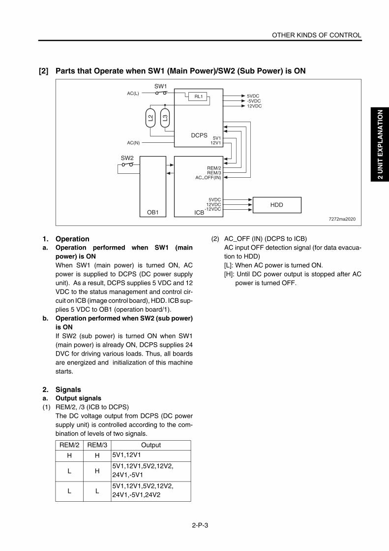
OTHER KINDS OF CONTROL
2-P-3
2 U
NIT
EX
PL
AN
AT
ION
[2] Parts that Operate when SW1 (Main Power)/SW2 (Sub Power) is ON
1. Operationa. Operation performed when SW1 (main
power) is ONWhen SW1 (main power) is turned ON, ACpower is supplied to DCPS (DC power supplyunit). As a result, DCPS supplies 5 VDC and 12VDC to the status management and control cir-cuit on ICB (image control board), HDD. ICB sup-plies 5 VDC to OB1 (operation board/1).
b. Operation performed when SW2 (sub power)is ONIf SW2 (sub power) is turned ON when SW1(main power) is already ON, DCPS supplies 24DVC for driving various loads. Thus, all boardsare energized and initialization of this machinestarts.
2. Signalsa. Output signals(1) REM/2, /3 (ICB to DCPS)
The DC voltage output from DCPS (DC powersupply unit) is controlled according to the com-bination of levels of two signals.
(2) AC_OFF (IN) (DCPS to ICB)AC input OFF detection signal (for data evacua-tion to HDD)[L]: When AC power is turned ON.[H]: Until DC power output is stopped after AC
power is turned OFF.
7272ma2020
AC(L) 5VDC-5VDC12VDC
5VDC12VDC
-12VDC
AC(N)5V1
12V1
REM/2REM/3
AC OFF(IN)
RL1
SW1
SW2
DCPS
ICBHDD
OB1
L2 L3
REM/2 REM/3 Output
H H 5V1,12V1
L H5V1,12V1,5V2,12V2,24V1,-5V1
L L5V1,12V1,5V2,12V2,24V1,-5V1,24V2

OTHER KINDS OF CONTROL
2-P-4
2 U
NIT
EX
PL
AN
AT
ION
[3] Cooling Fan Control
FM1 (main body cooling/1), FM2 (write sectioncooling), FM5 (cleaner cooling), FM6 (paper exit/F), FM7 (paper exit/R), and FM8 (main cooling/2) are controlled by PRCB (printer controlboard) directly. FM9 (scanner cooling) is drivenby SCDB (scanner drive board). FM10 (ADUreverse motor cooling) is driven by ADUDB (ADUdrive board) and is controlled by PRCB. FM13(power supply cooling) is driven by DCPS (DCpower supply unit).
1. OperationA 24 VDC motor is used for each cooling fan.
a. FM1 (main body cooling/1)(1) ON timing
• During warm-up, starts rotating at a low speedwhen M2 (drum) is turned ON.
• During copying, held rotating at a high speed.When copying is completed, rotates at a highspeed for the specified time according to thetemperature in the machine, then starts rotat-ing at a low speed.
7272ma2015
ADUDB
FM10
PRCB
SCDB
IO DTXDIO DCLK
ADU LATCHIO UCLK
REQ1IO URXD
ACK1ERR OUT1
DCPS
24V1P.GND
5V224V1
S.GND
ADU FAN/1
ADUFAN EM/1
P.GND
FM8
FM7
FM6
FM9
FM13
FM5
FIXFAN D
CLFAN EMCLNFAN DCLFAN HL
P.GND
FIXFAN3 EM
P.GND
24V DRV SCANFAN CONT-18SCANFAN EM
24V1P.GND
FAN1
FAN2
FAN3
EM
P.GND
FIXFAN D
FIXFAN2 EM
P.GND
FM2WRFAN1 EM
WRFAN1 DWRFAN1 HL
P.GND
FM1MAINFAN EM
MAINFAN DMAINFAN HL 20
P.GND
FIXFAN D
FIXFAN1 EM
P.GND
BINF_D
BINFF_EM
GND
FM12
(Di5510/Di7210)
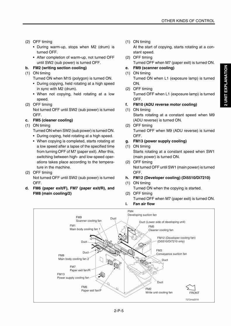
OTHER KINDS OF CONTROL
2-P-5
2 U
NIT
EX
PL
AN
AT
ION
(2) OFF timing• During warm-up, stops when M2 (drum) is
turned OFF.• After completion of warm-up, not turned OFF
until SW2 (sub power) is turned OFF.b. FM2 (writing section cooling)(1) ON timing
Turned ON when M15 (polygon) is turned ON.• During copying, held rotating at a high speed
in sync with M2 (drum).• When not copying, held rotating at a low
speed.(2) OFF timing
Not turned OFF until SW2 (sub power) is turnedOFF.
c. FM5 (cleaner cooling)(1) ON timing
Turned ON when SW2 (sub power) is turned ON.• During coping, held rotating at a high speed.• When copying is completed, starts rotating at
a low speed after a lapse of the specified timefrom turning OFF of M7 (paper exit). After this,switching between high- and low-speed oper-ations takes place according to the tempera-ture in the machine.
(2) OFF timingNot turned OFF until SW2 (sub power) is turnedOFF.
d. FM6 (paper exit/F), FM7 (paper exit/R), andFM8 (main cooling/2)
(1) ON timingAt the start of copying, starts rotating at a con-stant speed.
(2) OFF timingTurned OFF when M7 (paper exit) is turned ON.
e. FM9 (scanner cooling)(1) ON timing
Turned ON when L1 (exposure lamp) is turnedON.
(2) OFF timingTurned OFF when L1 (exposure lamp) is turnedOFF.
f. FM10 (ADU reverse motor cooling)(1) ON timing
Starts rotating at a constant speed when M9(ADU reverse) is turned ON.
(2) OFF timingTurned OFF when M9 (ADU reverse) is turnedOFF.
g. FM13 (power supply cooling)(1) ON timing
Starts rotating at a constant speed when SW1(main power) is turned ON.
(2) OFF timingNot turned OFF until SW1 (main power) is turnedOFF.
h. FM12 (Developer cooling) (Di5510/Di7210)(1) ON timing
Turned ON when the copying is started.(2) OFF timing
Turned OFF when M7 (paper exit) is turned ON.i. Fan air flow
7272ma2016
FRONT
FM9Scanner cooling fan
FM5Cleaner cooling fan
FM13Power supply cooling fan
FM3Conveyance suction fan
FM1Main body cooling fan 1
Duct (Lower side of developing unit)
Duct
Duct
Duct
Duct
Duct
FM2Write unit cooling fan
FM6Paper exit fan/F
FM7Paper exit fan/R
FM8Main body cooling fan 2
FM4Developing suction fan
FM12 (Developer cooling fan)(Di5510/Di7210 only)

OTHER KINDS OF CONTROL
2-P-6
2 U
NIT
EX
PL
AN
AT
ION
2. Signalsa. Input signals(1) MAINFAN_EM (FM1 to PRCB)
FM1 (main body cooling/1) abnormality detec-tion signal[H]: Abnormality is detected.
(2) WRFAN1_EM (FM2 to PRCB)FM2 (writing section cooling) abnormality detec-tion signal[H]: Abnormality is detected.
(3) CLFABN_EM (FM5 to PRCB)FM5 (cleaner cooling) abnormality detection sig-nal[H]: Abnormality is detected.
(4) FIXFAN3_EM (FM6 to PRCB)FM6 (paper exit/F) abnormality detection signal[L]: FM6 is normal.[H]: FM6 is abnormal
(5) FIXFAN2_EM (FM7 to PRCB)FM7 (paper exit/R) abnormality detection signal[L]: FM7 is normal.[H]: FM7 is abnormal.
(6) FIXFAN1_EM (FM8 to PRCB)FM8 (main cooling/2) abnormality detection sig-nal[L]: FM8 is normal.[H]: FM8 is abnormal.
(7) EM (FM9 to SCDB)FM9 (scanner cooling) abnormality detectionsignal[L]: FM9 is normal.[H]: FM9 is abnormal.
(8) ADUFAN_EM/1 (FM10 to PRCB)FM10 (ADU reverse motor cooling) abnormalitydetection signal[L]: FM10 is normal.[H]: FM10 is abnormal.
(9) FAN2 (FM13 to PRCB)FM13 (power supply cooling) abnormality detec-tion signal[L]: FM13 is normal.[H]: FM13 is abnormal.
(10) SCANFAN_EM (SCDB to PRCB)FM9 (scanner cooling) abnormality detectionsignal[L]: FM9 is normal.[H]: FM9 is abnormal.
(11) BINFF_EMFM12 (developer cooling) abnormality detectionsignal[L]: FM12 is normal[H]: FM12 is abnormal
b. Output signals(1) MAINFAN_D (PRCB to FM1)
FM1 (main body cooling/1) ON/OFF control signal[L]: FM1 ON[H]: FM1 OFF
(2) MAINFAN_HL_20 (PRCB to FM1)FM1 (main body cooling/1) rotational speed con-trol signal[L]: Low speed[H]: High speed
(3) WRFAN1_D (PRCB to FM2)FM2 (writing section cooling) ON/OFF controlsignal[L]: FM2 ON[H]: FM2 OFF
(4) WRFAN1_HL (PRCB to FM2)FM2 (write section cooling) rotational speed con-trol signal[L]: Low speed[H]: High speed
(5) CLNFAN_D (PRCB to FM5)FM5 (cleaner cooling) ON/OFF control signal[L]: FM5 ON[H]: FM5 OFF
(6) CLFFAN_D (PRCB to FM5)FM5 (cleaner cooling) rotational speed controlsignal[L]: Low speed[H]: High speed
(7) FIXFAN_D (PRCB to FM6)FM6 (paper exit/F) rotational speed control sig-nal[L]: Low speed[H]: High speed
(8) FIXFAN_D (PRCB to FM7)FM7 (paper exit/R) ON/OFF control signal[L]: FM7 ON[H]: FM7 OFF
(9) FIXFAN-D (PRCB to FM8)FM8 (main cooling/2) ON/OFF control signal[L]: FM8 ON[H]: FM8 OFF
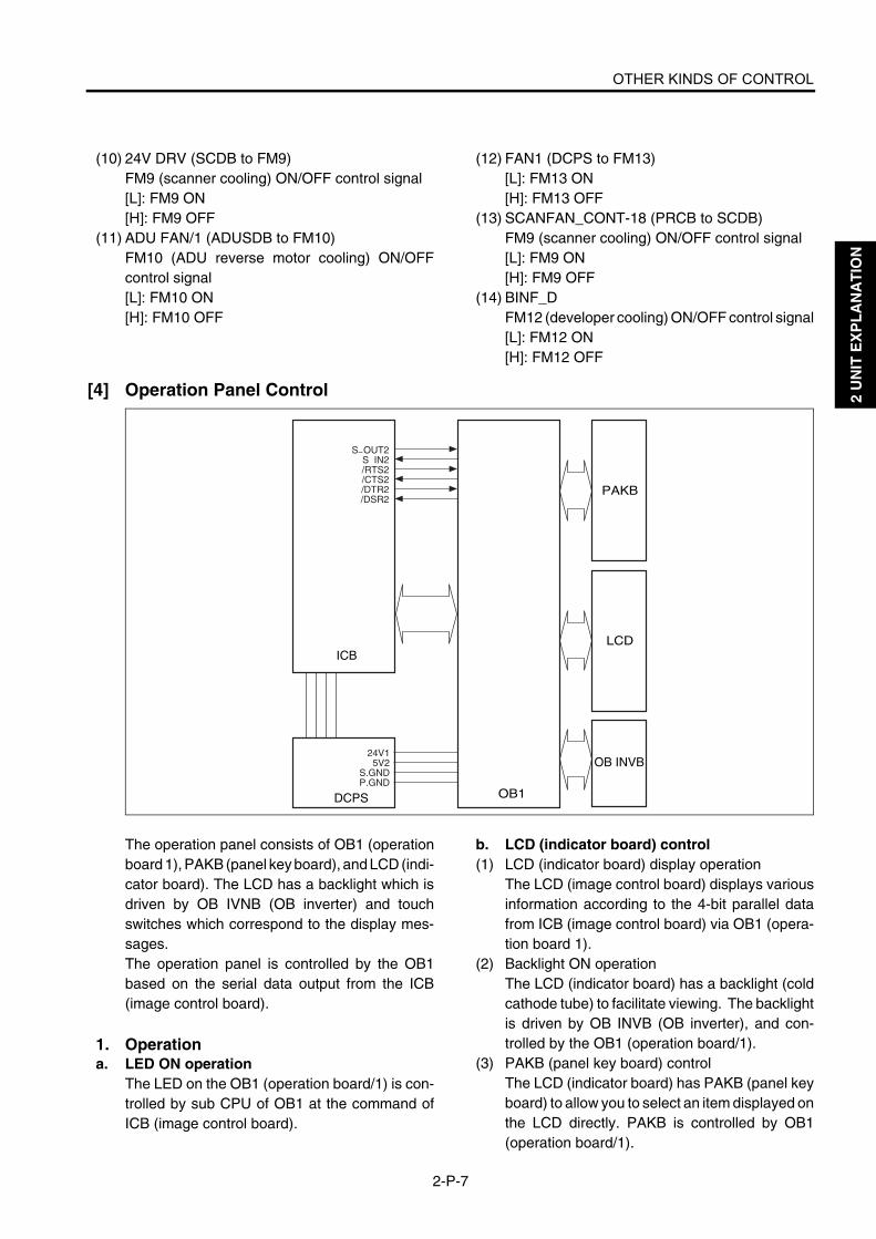
OTHER KINDS OF CONTROL
2-P-7
2 U
NIT
EX
PL
AN
AT
ION
(10) 24V DRV (SCDB to FM9)FM9 (scanner cooling) ON/OFF control signal[L]: FM9 ON[H]: FM9 OFF
(11) ADU FAN/1 (ADUSDB to FM10)FM10 (ADU reverse motor cooling) ON/OFFcontrol signal[L]: FM10 ON[H]: FM10 OFF
(12) FAN1 (DCPS to FM13)[L]: FM13 ON[H]: FM13 OFF
(13) SCANFAN_CONT-18 (PRCB to SCDB)FM9 (scanner cooling) ON/OFF control signal[L]: FM9 ON[H]: FM9 OFF
(14) BINF_DFM12 (developer cooling) ON/OFF control signal[L]: FM12 ON[H]: FM12 OFF
[4] Operation Panel Control
The operation panel consists of OB1 (operationboard 1), PAKB (panel key board), and LCD (indi-cator board). The LCD has a backlight which isdriven by OB IVNB (OB inverter) and touchswitches which correspond to the display mes-sages.The operation panel is controlled by the OB1based on the serial data output from the ICB(image control board).
1. Operationa. LED ON operation
The LED on the OB1 (operation board/1) is con-trolled by sub CPU of OB1 at the command ofICB (image control board).
b. LCD (indicator board) control(1) LCD (indicator board) display operation
The LCD (image control board) displays variousinformation according to the 4-bit parallel datafrom ICB (image control board) via OB1 (opera-tion board 1).
(2) Backlight ON operationThe LCD (indicator board) has a backlight (coldcathode tube) to facilitate viewing. The backlightis driven by OB INVB (OB inverter), and con-trolled by the OB1 (operation board/1).
(3) PAKB (panel key board) controlThe LCD (indicator board) has PAKB (panel keyboard) to allow you to select an item displayed onthe LCD directly. PAKB is controlled by OB1(operation board/1).
OB1
LCD
PAKB
OB INVB
DCPS
ICB
24V15V2
S.GNDP.GND
S OUT2S IN2/RTS2/CTS2/DTR2/DSR2

OTHER KINDS OF CONTROL
2-P-8
2 U
NIT
EX
PL
AN
AT
ION
2. Signalsa. Input signals(1) S_IN2 (OB1 to ICB)
Serial data which informs ICB (image controlboard) of the operation state of OB1 (operationboard/1).
(2) /CTS2 (OB1 to ICB)Signal which indicates that data can be sent fromOB1 (operation board/1) to ICB (image controlboard)When this signal is at the high level ([H]), ICBstops sending the S_OUT2 signal.
(3) /DSR2 (OB1 to ICB)Acknowledgment signal which is returned eachtime OB1 (operation board/1) receives one-bytedata from ICB (image control board)
b. Output signals(1) S_OUT2 (ICB to OB1)
Serial data which informs OB1 (operation board/1) of the machine status that is known to ICB(image control board).
(2) /RTS2 (ICB to OB1)Signal which indicates that data can be sent fromICB (image control board) to OB1 (operationboard/1).When this signal is at the high level ([H]), OB1stops sending the S_IN2 signal.
(3) /DTR2 (ICB to OB1)Acknowledgment signal which is returned eachtime ICB (image control board) receives one-byte data from OB1 (operation board/1).

OTHER KINDS OF CONTROL
2-P-9
2 U
NIT
EX
PL
AN
AT
ION
[5] Counter Control
This machine has the following counters:C (T): Total counterC (K): Key counterThese counters are controlled by the PRCB(printer control board).The related signal is PS37 (paper exit).
1. OperationThis machine counts copies using a softwarecounter.
(1) Paper exit counterThe count increases by 1 each time PS37 (paperexit) which has been ON is turned OFF (twocounts in the dual-sided document copy mode).<Operation of each counter>
a. Copy quantity display counter on OBDisplays the count of ejected papers
b. C (K)This counter counts in sync with the paper exitcounter.
c. C (T)This counter counts in sync with the paper exitcounter.
2. Signalsa. PRCB input signals(1) KSYC_SET (C (K) to PRCB)
Signal indicating the state of 24 V power supplyto C (K)[L]: 24V power is not supplied.
b. Output signals(1) TC_DRV (PRCB to C (T))
C (T) drive control signal[L]: C (T) ON
(2) KEYC_DRV (PRCB to C (K))C (K) drive control signal[L]: C (K) ON
OB1PRCB DCPS
ICB
24V15V2
S.GNDP.GND
MC24V 3TC DRV
KEYC DRVS.GND
KEYC SETMC24V 3
S OUT2S IN2/RTS2/CTS2/DTR2/DSR2
PS37
C(K)
C(T)
5VMAINEXIT PS
S.GND

OTHER KINDS OF CONTROL
2-P-10
2 U
NIT
EX
PL
AN
AT
ION
[6] Option Control
Options such as LCT and FNS are controlled bythe PRCB (printer control board).
1. OperationFNS incorporates CB which exchanges onlycontrol data with PRCB (printer control board) ofthe main body. LCT, FNS, and HDD are poweredby the DCPS (DC power supply unit).
7272ma2021
ICB
CV(COPY VENDOR)
FNS(FN-112/FN-6/FN-121/FN-10/FN-113/FN-122)
LCT(C-403/C-404)
SF(OT-104)
MODEM
HDD
DCPSPRCB
24V1P.GND
5V2S.GND
12V1

OTHER KINDS OF CONTROL
2-P-11
2 U
NIT
EX
PL
AN
AT
ION
<Functions and output timings of signals for copy vendors>
Connector Pin No. Signal name Description Output timing Signal type
35
1 DV24V Key counter power supply Always 24 V, 300 mA
2C(K) SIG Key counter connection rec-
ognition - -
3 C(K) GND Signal ground
4C(K) DRIVE Key counter signal count up 100-ms L-signal output
after paper ejection -
5 P. GND Power ground - -
36
1
Vendor Copy Copying signal Output from the moment START PRINT button is pressed to the moment paper ejection is com-pleted.
Open collector5V, 200 mA
2
Vendor FEED Paper feed signal Common to main body tray. 100-ms L-signal output in sync with paper feed.
3 Paper size 0 Paper size signal Output when paper size is changed. 4 Paper size 1
5 Paper size 2
6 Paper size 3
7Vendor screen
Double-sided copy selec-tion signal
Output when ADU mode is selected.
8CPF SIG0 CPF mode selection signal Output when copy or
printer mode is selected.
9 CPF SIG1
10 P. GND Power ground - -

2 U
NIT
EX
PL
AN
AT
ION
Blank page

3
3 D
IS./A
SS
EM
BL
Y
DISASSEMBLY/ASSEMBLY

3 D
IS./A
SS
EM
BL
Y
This section explains how to disassemble and reassemble the machine.When disassembling and reassembling the machine, follow the precau-tions given below.1. Be sure the power cord has been unplugged from the wall outlet.2. The disassembled parts must be reassembled following the disas-
sembly procedure in reverse unless otherwise specified.3. Care should be taken not to lose small parts. Care should also be
taken not to install small parts in wrong places.4. Do not operate the machine before installing all the disassembled
parts completely.5. Removal of some screws is prohibited in this section. Never loosen
them.

EXTERNAL SECTION
3-A-1
3 D
IS./A
SS
EM
BL
Y
EXTERNAL SECTION
[1] Replacing the Ozone FilterIn the case of the Di551/Di650
Caution:Be sure the power cord has beenunplugged from the wall outlet.
Caution: When replacing the ozone filter, insert it in the opening in the main body as far as it will go.
a. Procedure(1) Loosen two screws to remove the ozone filter
cover.
(2) Replace the ozone filter.
(3) Reinstall the above parts following the removal steps in reverse.
In the case of the Di5510/Di7210
Caution:Be sure the power cord has beenunplugged from the wall outlet.
Caution: When replacing the ozone filter /M and /S, insert it in the opening in the main body as far as it will go.
b. Procedure(1) Loosen two screws to remove the ozone filter
cover.
(2) Replace the ozone filter /M and /S.
(3) Reinstall the above parts following the removal steps in reverse.
Screw
Ozone filter cover
Screw
Ozone filter
Ozone filter cover
Screw
Ozone filter cover
Screw
7272ma3001
Ozone filter /SOzone filter /M
Ozone filter cover

EXTERNAL SECTION
3-A-2
3 D
IS./A
SS
EM
BL
Y
[2] Replacing the Developing Suction Fil-ter
Caution:Be sure the power cord has beenunplugged from the wall outlet.
Caution: When replacing the developing suc-tion filter, insert it in the opening in the main body as far as it will go.
a. Procedure(1) Loosen the screw to remove the developing suc-
tion filter cover.(2) Replace the developing suction filter.
(3) Reinstall the above parts following the removalsteps in reverse.
Caution: When installing the developing suc-tion filter, the filter-supporting material should face the back of the machine.
Developing suction filter cover
Developing suction filter
Screw

EXTERNAL SECTION
3-A-3
3 D
IS./A
SS
EM
BL
Y
[3] Removing and Reinstalling the Exter-nal Covers
Caution:Be sure the power cord has beenunplugged from the wall outlet.
a. Procedure(1) Remove fourteen screws to detach the rear
cover.
Caution: The ozone filter cover and the option cover detach together with the rear cover.
(2) Remove seven screws to detach the left sidecover.
Option cover
ScrewsScrews
ScrewsScrew
Screws
Ozone filter cover
Rear cover
Screw
Screws
Screws
Screw
Left side cover

EXTERNAL SECTION
3-A-4
3 D
IS./A
SS
EM
BL
Y
(3) Loosen one screw and remove the developingsuction filter cover.
(4) Loosen five screws and detach the right sidecover (upper).
Caution: The developing suction filter cover detaches together with the right side cover (upper).
(5) Loosen two screws to detach the right side cover(lower front).
(6) Loosen two screws to detach the right side cover(lower rear).
(7) Loosen two screws to detach the right side cover(lower middle).
(8) Open the RADF.(9) Remove the two shoulder screws to remove the
original stopper plate (left).(10) Remove the three shoulder screws to remove the
original stopper plate (rear).(11) Remove the platen glass.(12) Remove two screws to detach the top cover (left).(13) Remove two screws to detach the top cover
(right).
(14) Remove the top cover (middle front) and topcover (middle rear).
Screws
Screws
ScrewsScrews
Screws
Right side cover (upper)
Developing suction filter cover
Right side cover (lower rear)
Right side cover (lower middle)Right side cover
(lower front)
Original stopper plate (rear)
Shoulder screwsTop cover (middle rear)
Top cover (left)Top cover (right)
Screws
Top cover (middle front)
Platen glass
Original stopper plate (left)
Shoulder screws
Screws
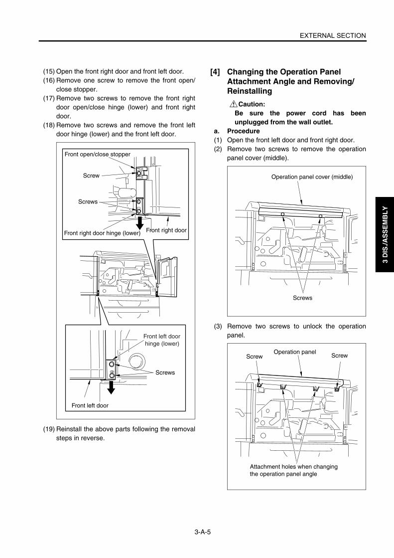
EXTERNAL SECTION
3-A-5
3 D
IS./A
SS
EM
BL
Y
(15) Open the front right door and front left door.(16) Remove one screw to remove the front open/
close stopper.(17) Remove two screws to remove the front right
door open/close hinge (lower) and front rightdoor.
(18) Remove two screws and remove the front leftdoor hinge (lower) and the front left door.
(19) Reinstall the above parts following the removalsteps in reverse.
[4] Changing the Operation Panel Attachment Angle and Removing/Reinstalling
Caution:Be sure the power cord has beenunplugged from the wall outlet.
a. Procedure(1) Open the front left door and front right door.(2) Remove two screws to remove the operation
panel cover (middle).
(3) Remove two screws to unlock the operationpanel.Front left door
hinge (lower)
Front open/close stopper
Screw
Front right door hinge (lower)
Screws
Front right door
Screws
Front left door
Operation panel cover (middle)
Screws
Operation panel
Attachment holes when changing the operation panel angle
ScrewScrew

EXTERNAL SECTION
3-A-6
3 D
IS./A
SS
EM
BL
Y
(4) When changing the operation panel attachmentangle, align the operation panel stopper with thestopper hole at the front side on the bottom of theoperation panel and fasten using two screws inthe operation cover attachment holes.Caution1: To remove the operation panel, skip
this step and proceed to step (5). Caution2: When the attachment angle of the
operation panel is changed, theoperation panel cover and twoscrews will become unnecessary.
(5) Remove the relay connectors (CN163, 164).
Caution: Each relay connector consist of two male sides and one female side. Be sure to remove only the male side (shown below).
(6) Remove the operation panel.
(7) Reinstall the above parts following the removalsteps in reverse.
Stopper hole
Operation panel stopper
Stopper hole Operation panel
Stopper hole
Screws
Operation panel stopper
Relay connector (CN163)
Relay connector (CN164)
Operation panel
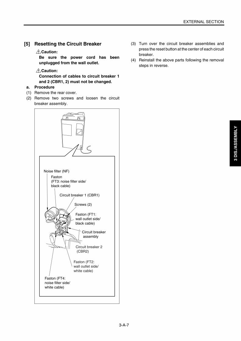
EXTERNAL SECTION
3-A-7
3 D
IS./A
SS
EM
BL
Y
[5] Resetting the Circuit Breaker
Caution:Be sure the power cord has beenunplugged from the wall outlet.
Caution:Connection of cables to circuit breaker 1and 2 (CBR1, 2) must not be changed.
a. Procedure(1) Remove the rear cover.(2) Remove two screws and loosen the circuit
breaker assembly.
(3) Turn over the circuit breaker assemblies andpress the reset button at the center of each circuitbreaker.
(4) Reinstall the above parts following the removalsteps in reverse.
Noise filter (NF)
Circuit breaker 1 (CBR1)
Faston (FT3: noise filter side/black cable)
Screws (2)
Faston (FT1: wall outlet side/black cable)
Circuit breaker assembly
Faston (FT4: noise filter side/white cable)
Circuit breaker 2 (CBR2)
Faston (FT2: wall outlet side/white cable)

3 D
IS./A
SS
EM
BL
Y
Blank page

DRIVE SECTION
3-B-1
3 D
IS./A
SS
EM
BL
Y
DRIVE SECTION
[1] Removing and Reinstalling the Drum Motor(M2)
Caution:Be sure the power cord has beenunplugged from the wall outlet.
Caution: Be sure to draw the drum unit out of the main body before removing or reinstalling the drum drive motor. If you fail to draw out the drum unit, the cleaning blade may be damaged because the drum rotates when installing or removing the flywheel or gear.
a. Procedure(1) Draw the drum unit out of the main body. (See
"DRUM UNIT.")(2) Remove the rear cover. (See "EXTERNAL SEC-
TION.")(3) Remove the developing suction cover and right
cover (top). (See "EXTERNAL SECTION.")(4) Remove twenty-one screws and remove the
image control board cover.
(5) Remove five screws at the rear and three screwson the right side and remove all connectors fromthe image control board (ICB).
Caution: When removing CN110 ribbon cable, pull and recline the lock lever front-ward, release the lock, and then pull out the ribbon cable.
Screws (4)
Image control board cover
Screws (7)
Screws (5)
Screws (5)
Screws (3)
Screws (2)
Screws (3)
Image control board (ICB)
Image control board mounting board
7272ma3002
Ribbon cable
Lock lever
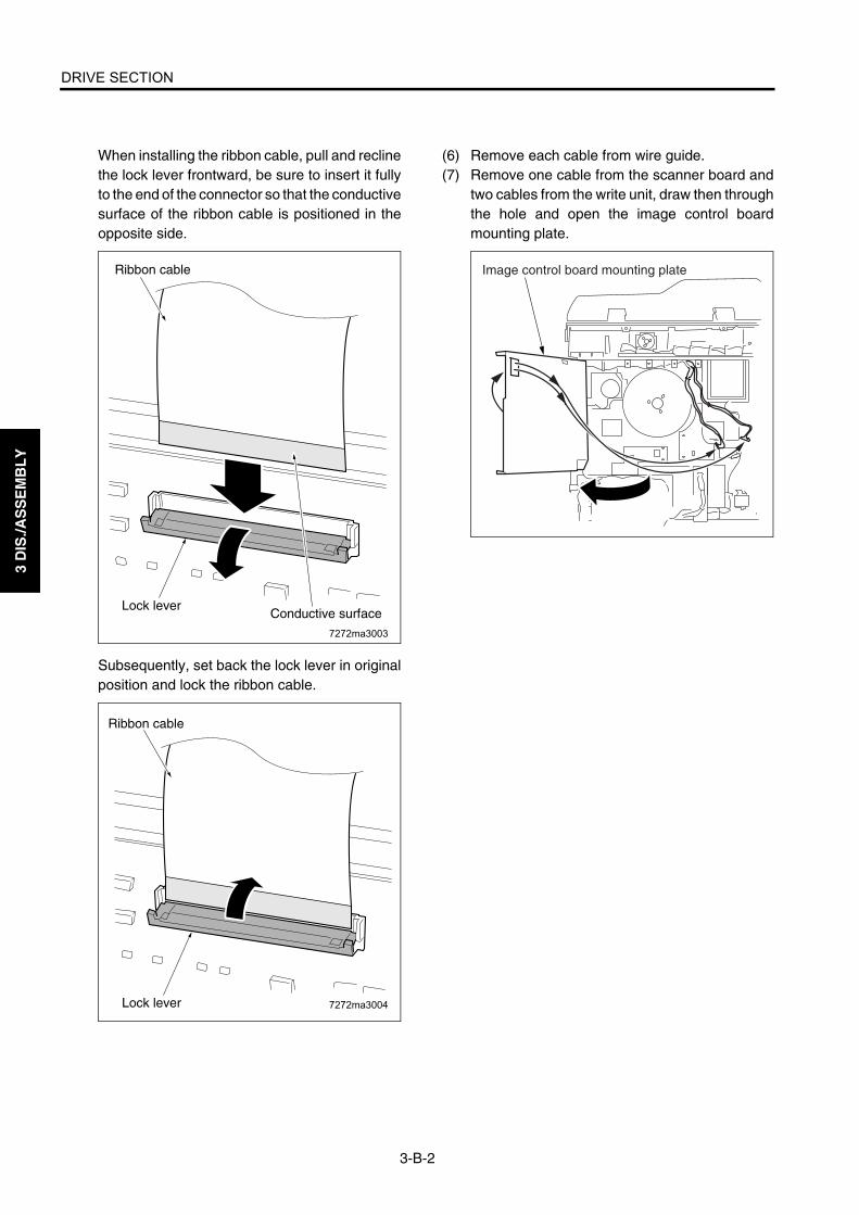
DRIVE SECTION
3-B-2
3 D
IS./A
SS
EM
BL
Y
When installing the ribbon cable, pull and reclinethe lock lever frontward, be sure to insert it fullyto the end of the connector so that the conductivesurface of the ribbon cable is positioned in theopposite side.
Subsequently, set back the lock lever in originalposition and lock the ribbon cable.
(6) Remove each cable from wire guide.(7) Remove one cable from the scanner board and
two cables from the write unit, draw then throughthe hole and open the image control boardmounting plate.
7272ma3003
Conductive surfaceLock lever
Ribbon cable
7272ma3004Lock lever
Ribbon cable
Image control board mounting plate
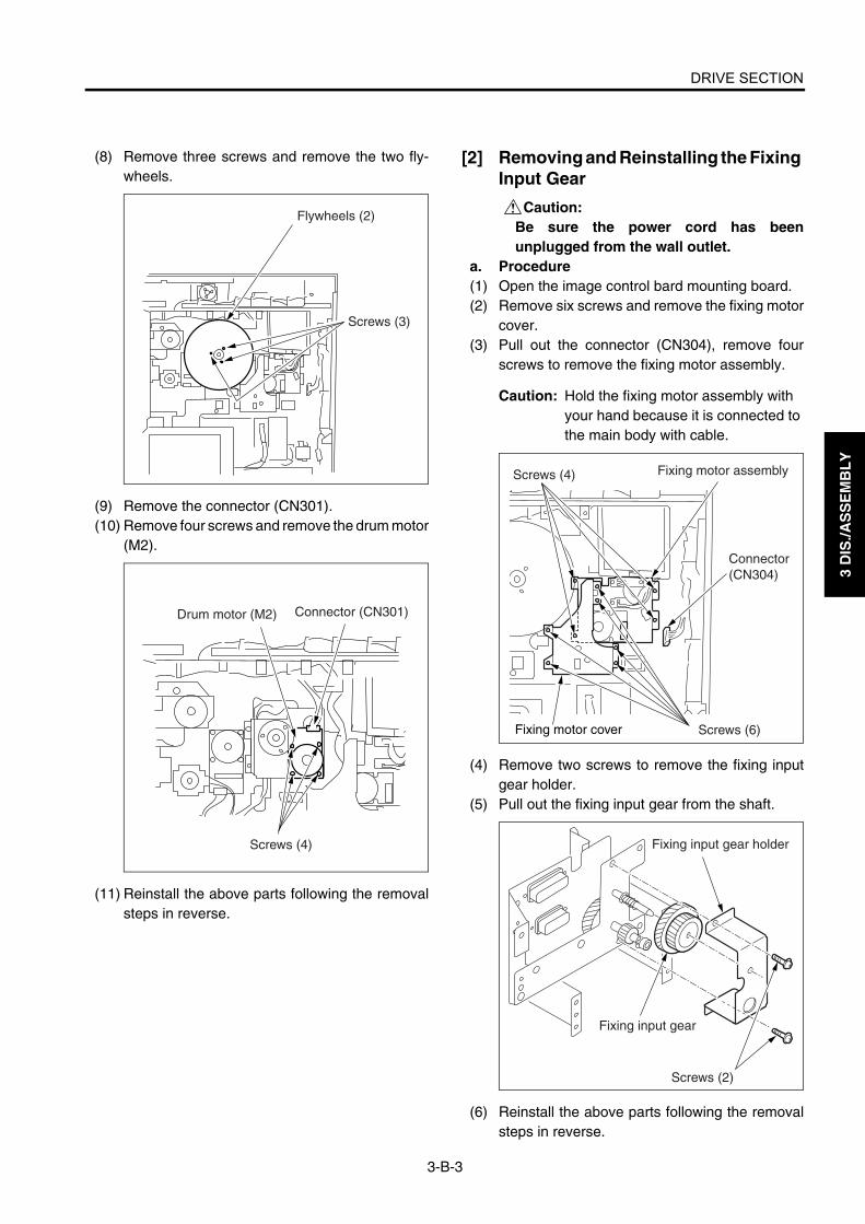
DRIVE SECTION
3-B-3
3 D
IS./A
SS
EM
BL
Y
(8) Remove three screws and remove the two fly-wheels.
(9) Remove the connector (CN301).(10) Remove four screws and remove the drum motor
(M2).
(11) Reinstall the above parts following the removalsteps in reverse.
[2] Removing and Reinstalling the Fixing Input Gear
Caution:Be sure the power cord has beenunplugged from the wall outlet.
a. Procedure(1) Open the image control bard mounting board.(2) Remove six screws and remove the fixing motor
cover.(3) Pull out the connector (CN304), remove four
screws to remove the fixing motor assembly.
Caution: Hold the fixing motor assembly with your hand because it is connected to the main body with cable.
(4) Remove two screws to remove the fixing inputgear holder.
(5) Pull out the fixing input gear from the shaft.
(6) Reinstall the above parts following the removalsteps in reverse.
Flywheels (2)
Screws (3)
Drum motor (M2) Connector (CN301)
Screws (4)
Screws (4)
Screws (6)
Connector (CN304)
Fixing motor assembly
Fixing motor cover
Fixing input gear holder
Fixing input gear
Screws (2)

3 D
IS./A
SS
EM
BL
Y
Blank page

SCANNER SECTION
3-C-1
3 D
IS./A
SS
EM
BL
Y
SCANNER SECTION
[1] Screws that Must not be Removeda. 14 screws securing the CCD unit
b. Read position adjusting plate screw (1 each)
[2] Removing and Reinstalling the CCD Unit
Caution:Be sure the power cord has beenunplugged from the wall outlet.
Caution1: Be sure to adjust the image afterinstalling the CCD unit (See"ADJUSTMENT.")
Caution2: When disconnecting or reconnectingconnectors from / to the AD con-verter board, be careful not to placeany stress on the board.
a. Procedure(1) Remove the right side cover (top), left side cover,
original stopper plates (left and rear), platenglass and top cover (right, left, front center, andrear center). (See "EXTERNAL SECTION.")
(2) Remove eleven screws to remove the lens lightblocking cover.
(3) Remove the connector (CN170) from the A/Dconverter board (ADB).In the case of the Di551/Di650
Screws that must not be removed
Screws that must not be removed
Screws that must not be removed
Read position adjusting plate (right rear)
Read position adjusting plate (left front)
Read position adjusting plate (left rear)
Screws that must not be removed
Screws that must not be removed
Screws that must not be removed
Lens light blocking cover
Screws (11)
CCD unit
Connector (CN170)
A/D converter board (ADB)
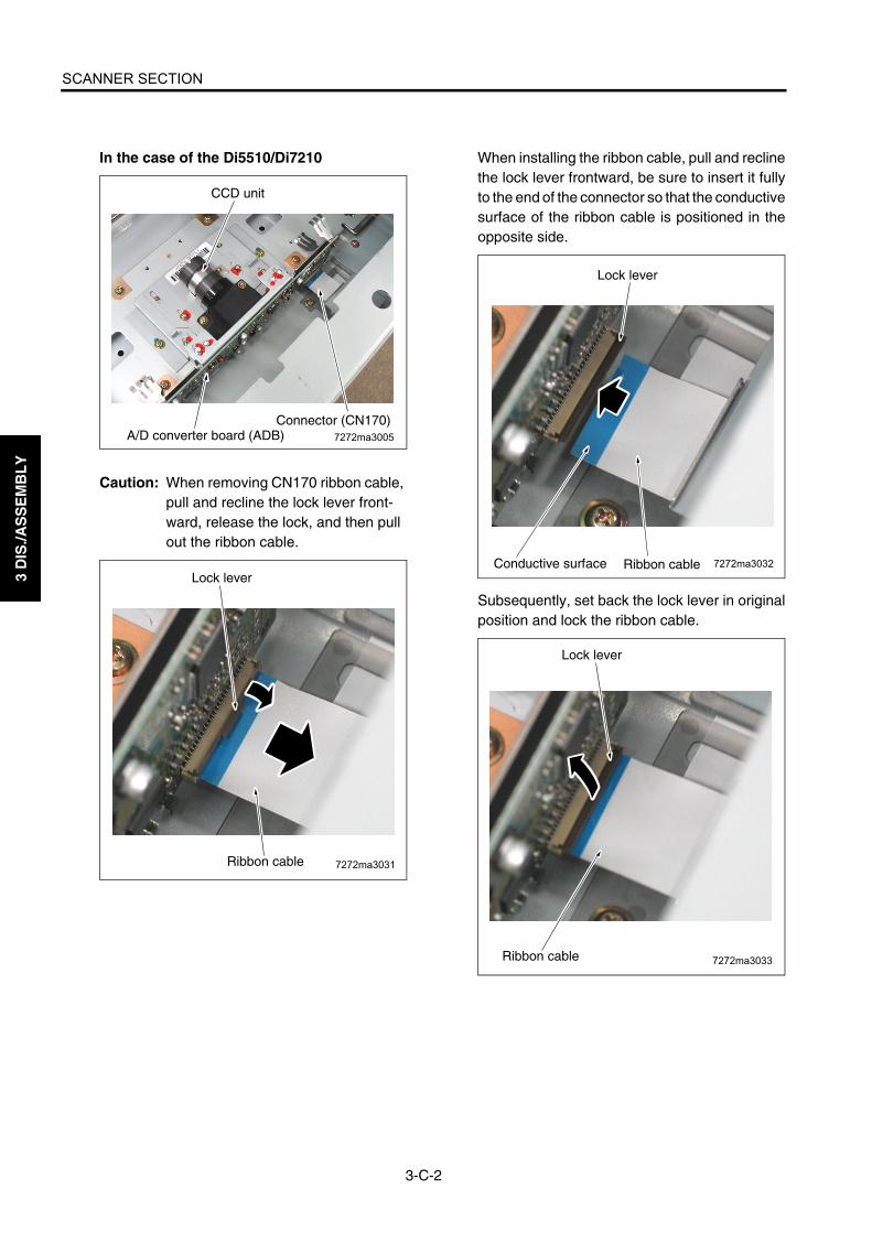
SCANNER SECTION
3-C-2
3 D
IS./A
SS
EM
BL
Y
In the case of the Di5510/Di7210
Caution: When removing CN170 ribbon cable, pull and recline the lock lever front-ward, release the lock, and then pull out the ribbon cable.
When installing the ribbon cable, pull and reclinethe lock lever frontward, be sure to insert it fullyto the end of the connector so that the conductivesurface of the ribbon cable is positioned in theopposite side.
Subsequently, set back the lock lever in originalposition and lock the ribbon cable.
7272ma3005A/D converter board (ADB)Connector (CN170)
CCD unit
7272ma3031Ribbon cable
Lock lever7272ma3032Conductive surface
Lock lever
Ribbon cable
7272ma3033
Lock lever
Ribbon cable

SCANNER SECTION
3-C-3
3 D
IS./A
SS
EM
BL
Y
(4) Remove two screws to remove the CCD unit.
Caution: Mark the place where the CCD unit is installed before removing it.
(5) Reinstall the above parts following the removalsteps in reverse.
[3] Replacing the Exposure Lamp
Caution1:Be sure the power cord has beenunplugged from the wall outlet.
Caution2:Do not touch the exposure lamp with barehands.
Caution: Be sure to check the image after installing the exposure lamp. (See "ADJUSTMENTS.")
a. Procedure(1) Remove the original stopper plates (left and
rear), platen glass and top cover (right, middlefront, and middle rear). (See "EXTERNAL SEC-TION.")
(2) Move the exposure unit to the notch in the mainbody frame on the paper exit side.
(3) Remove the connector and two screws, thenremove the exposure lamp.
(4) Reinstall the above parts following the removalsteps in reverse.
Screws
CCD unitMarking
Marking
Screw
Screw
Exposure lamp
Exposure lamp
Connector

SCANNER SECTION
3-C-4
3 D
IS./A
SS
EM
BL
Y
[4] Removing and Reinstalling the Expo-sure Unit
Caution:Be sure the power cord has beenunplugged from the wall outlet.
Caution1: When installing the exposure unit,use the optics unit positioning jig.
Caution2: Be sure to perform image adjust-ment after installing the exposureunit. (See "ADJUSTMENT.")
a. Procedure(1) Remove the right side cover (top), left side cover,
original stopper plates (left and rear), platenglass and top cover (right, left, front center, andrear center). (See "EXTERNAL SECTION.")
(2) Remove the operation panel. (See "EXTERNALSECTION.")
(3) Remove the relay connector (CN162).
Caution: Each relay connector consist of two male sides and one female side. Be sure to remove only the male side (shown below) of the CN162 connec-tor.
(4) Loosen the left and right screws on the operationpanel cover (top).
(5) Remove three screws and remove the operationunit cover (top).
(6) Move the exposure unit to the notch in the mainbody frame on the paper exit side.
(7) Remove two screws to detach the cord clamp(B).
(8) Remove one screw to remove the ground termi-nal.
(9) Disconnect the connector (CN630).(10) Remove four screws to detach the exposure unit.
Relay connector (CN162)
Operation panel cover (top)
Screws (loosen)Screws (loosen)
Screws
Cord clamp (B)
Optical wire fastener
Screws
Screws
Screw
Ground terminal
Connector (CN630)Exposure unit
Exposure unit
Exposure unit
Screws
Optical wire fastener
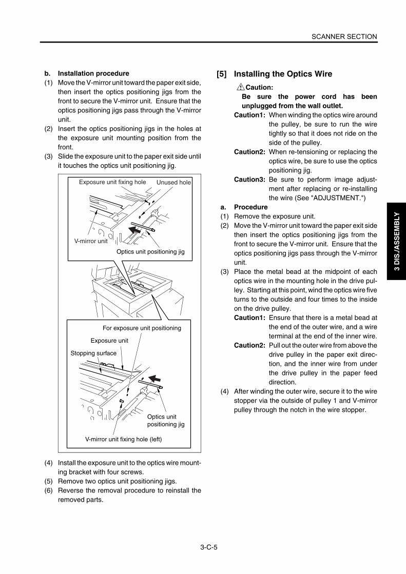
SCANNER SECTION
3-C-5
3 D
IS./A
SS
EM
BL
Y
b. Installation procedure(1) Move the V-mirror unit toward the paper exit side,
then insert the optics positioning jigs from thefront to secure the V-mirror unit. Ensure that theoptics positioning jigs pass through the V-mirrorunit.
(2) Insert the optics positioning jigs in the holes atthe exposure unit mounting position from thefront.
(3) Slide the exposure unit to the paper exit side untilit touches the optics unit positioning jig.
(4) Install the exposure unit to the optics wire mount-ing bracket with four screws.
(5) Remove two optics unit positioning jigs.(6) Reverse the removal procedure to reinstall the
removed parts.
[5] Installing the Optics Wire
Caution:Be sure the power cord has beenunplugged from the wall outlet.
Caution1: When winding the optics wire aroundthe pulley, be sure to run the wiretightly so that it does not ride on theside of the pulley.
Caution2: When re-tensioning or replacing theoptics wire, be sure to use the opticspositioning jig.
Caution3: Be sure to perform image adjust-ment after replacing or re-installingthe wire (See "ADJUSTMENT.")
a. Procedure(1) Remove the exposure unit.(2) Move the V-mirror unit toward the paper exit side
then insert the optics positioning jigs from thefront to secure the V-mirror unit. Ensure that theoptics positioning jigs pass through the V-mirrorunit.
(3) Place the metal bead at the midpoint of eachoptics wire in the mounting hole in the drive pul-ley. Starting at this point, wind the optics wire fiveturns to the outside and four times to the insideon the drive pulley.Caution1: Ensure that there is a metal bead at
the end of the outer wire, and a wireterminal at the end of the inner wire.
Caution2: Pull out the outer wire from above thedrive pulley in the paper exit direc-tion, and the inner wire from underthe drive pulley in the paper feeddirection.
(4) After winding the outer wire, secure it to the wirestopper via the outside of pulley 1 and V-mirrorpulley through the notch in the wire stopper.
Exposure unit fixing hole
V-mirror unit
Unused hole
Exposure unit
Stopping surface
For exposure unit positioning
V-mirror unit fixing hole (left)
Optics unit positioning jig
Optics unit positioning jig

SCANNER SECTION
3-C-6
3 D
IS./A
SS
EM
BL
Y
Caution: There are two grooves in the wire stopper. Ensure that the outer groove is at the rear and the inner groove is at the front.
(5) Reverse the inner wire at pulley 2, pass it alongthe inside of the V-mirror pulley and pulley 3, thenattach the wire terminal to the spring fixing plate.At this time, secure the spring fixing plate tem-porarily with one screw.
(6) Install the other wire following the same proce-dure.
(7) Loosen each screw that was tightened tempo-rarily, install the spring on the spring fixing plate,and tighten each screw.
Metal bead
Four turns
Five turns
Front
Metal bead
Wire stopper
Front
3 4 3
5
6
7
4
Rear
Four turns
Metal beadMetal beadFive turns
Metal bead
Wire stopper
Exposure unit mounting piece
Wire stopperV-mirror pulley
V-mirror unit
Pulley 3
Pulley 2
Spring fixing plate
Spring
Screws
Spring fixing plate
Exposure unit mounting piece
Pulley 3
Pulley 2
V-mirror pulley
Drive pulley
Drive pulley
Wire stopper
Pulley 1
Pulley 1

SCANNER SECTION
3-C-7
3 D
IS./A
SS
EM
BL
Y
[6] Cleaning the Slit Glass and Platen Glass
Caution:Be sure the power cord has beenunplugged from the wall outlet.
(1) Remove the original stopper plates (left andrear), platen glass, and top cover (right, left, frontcenter, and rear center). (See "EXTERNAL SEC-TION.")
(2) Remove two screws to detach the slit glass.(3) Place the removed slit glass and platen glass on
a rag and clean with isopropyl alcohol and waste.
(4) Reinstall the above parts following the removalsteps in reverse.
[7] Replacing the Scanner Motor (M11)
Caution:Be sure the power cord has beenunplugged from the wall outlet.
a. Procedure(1) Remove the RADF unit, original stopper plates
(left and rear), platen glass, and top cover (right,left, front center, and rear center). (See "EXTER-NAL SECTION.")
(2) Remove one connector (CN639) from the APStiming PS (PS51).
(3) Remove the hinge mounting plate (rear side)from the scanner unit. (12 screws)
(4) Remove four screws from the scanner motor(M11), then remove the scanner belt and thescanner motor.
Screw
Screw
Slit glass
Slit glass
Connector(CN639)
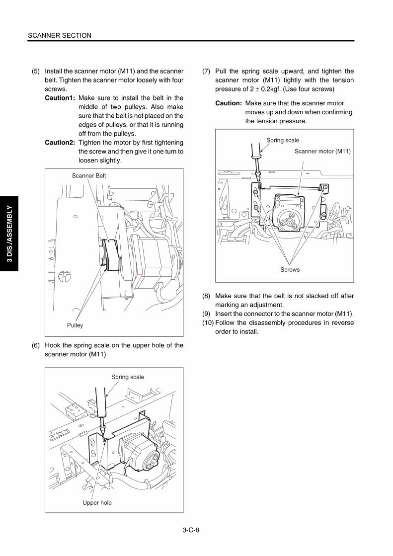
SCANNER SECTION
3-C-8
3 D
IS./A
SS
EM
BL
Y
(5) Install the scanner motor (M11) and the scannerbelt. Tighten the scanner motor loosely with fourscrews.Caution1: Make sure to install the belt in the
middle of two pulleys. Also makesure that the belt is not placed on theedges of pulleys, or that it is runningoff from the pulleys.
Caution2: Tighten the motor by first tighteningthe screw and then give it one turn toloosen slightly.
(6) Hook the spring scale on the upper hole of thescanner motor (M11).
(7) Pull the spring scale upward, and tighten thescanner motor (M11) tightly with the tensionpressure of 2 ± 0.2kgf. (Use four screws)
Caution: Make sure that the scanner motor moves up and down when confirming the tension pressure.
(8) Make sure that the belt is not slacked off aftermarking an adjustment.
(9) Insert the connector to the scanner motor (M11).(10) Follow the disassembly procedures in reverse
order to install.
Scanner Belt
Pulley
Spring scale
Upper hole
Spring scale
Scanner motor (M11)
Screws

WRITE SECTION
3-D-1
3 D
IS./A
SS
EM
BL
Y
WRITE SECTION
[1] Removing and Reinstalling the Write UnitIn the case of the Di551/Di650
Warning:(1) Do not energize the write unit when it is
not in the correct position.(2) Never remove the write unit cover and
the polygon unit cover.(3) Never look directly into the laser beam. It
can cause blindness.(4) Never remove the write unit for at least
two minutes after turning OFF the mainswitch.
Caution:Be sure the power cord has beenunplugged from the wall outlet.
a. Procedure(1) Remove the left side cover. (See "EXTERNAL
SECTION.")(2) Remove nine screws to detach the fan holder
assembly.(3) Remove the relay connector (CN338).
Caution: Each relay connector consists of two male sides and one female side. Be sure to remove only the male side (shown below) of the CN338 connec-tor.
(4) Remove the three connectors (CN185, 187,188).
(5) Loosen the screw to draw out and remove thewrite unit.
(6) Reinstall the above parts following the removalsteps in reverse.
Fan holder assembly
Relay connector (CN338)
ScrewsScrewsScrews
Connector (CN187)
Connector (CN185)
Connector (CN188)
ScrewWrite unit
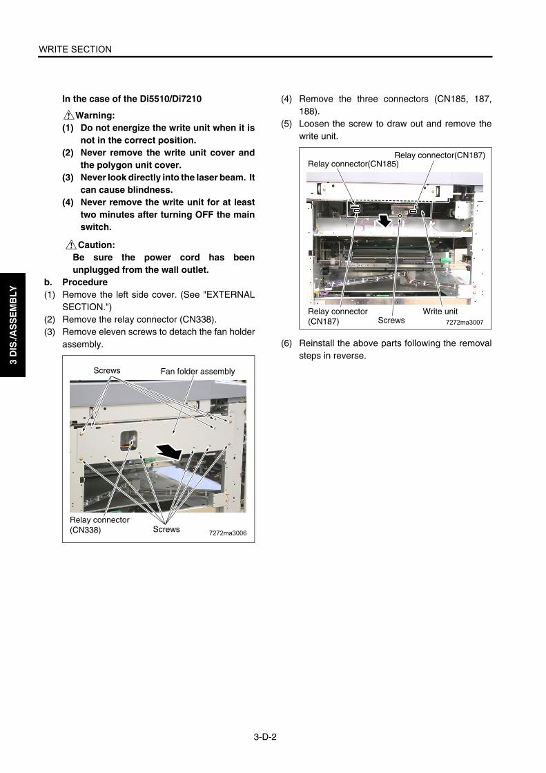
WRITE SECTION
3-D-2
3 D
IS./A
SS
EM
BL
Y
In the case of the Di5510/Di7210
Warning:(1) Do not energize the write unit when it is
not in the correct position.(2) Never remove the write unit cover and
the polygon unit cover.(3) Never look directly into the laser beam. It
can cause blindness.(4) Never remove the write unit for at least
two minutes after turning OFF the mainswitch.
Caution:Be sure the power cord has beenunplugged from the wall outlet.
b. Procedure(1) Remove the left side cover. (See "EXTERNAL
SECTION.")(2) Remove the relay connector (CN338).(3) Remove eleven screws to detach the fan holder
assembly.
(4) Remove the three connectors (CN185, 187,188).
(5) Loosen the screw to draw out and remove thewrite unit.
(6) Reinstall the above parts following the removalsteps in reverse.
7272ma3006
Fan folder assemblyScrews
ScrewsRelay connector(CN338)
7272ma3007ScrewsRelay connector(CN187)
Write unit
Relay connector(CN187)Relay connector(CN185)

WRITE SECTION
3-D-3
3 D
IS./A
SS
EM
BL
Y
[2] Cleaning the Dust-proof Glass
Caution:Be sure the power cord has beenunplugged from the wall outlet.
a. Procedure(1) Remove the write unit.(2) Clean the dust-proof glass at the bottom of the
write unit with waste and blower brush.
(3) Reinstall the above parts following the removalsteps in reverse.
Write unit
Dust-proof glass

3 D
IS./A
SS
EM
BL
Y
Blank page

DRUM UNIT
3-E-1
3 D
IS./A
SS
EM
BL
Y
DRUM UNIT
[1] Removing and Reinstalling the Drum Unit
Caution:Be sure the power cord has beenunplugged from the wall outlet.
Caution1: Be sure to put a drum cover over theremoved drum unit and store thedrum unit in a dark place.
Caution2: When installing or removing thedrum unit, do not rotate it in the direc-tion opposite to the specified one.Rotating the drum unit in the oppo-site direction during copy operationcould damage the cleaning blade.
Caution3: When installing or removing thedrum unit, take care not to touch theseparation claw.
Caution4: When installing a new drum, be sureto enter mode 25 and select "CopyCount by Parts to be Replaced" toreset OPC drum counter.
a. Procedure(1) Open the left and right front doors.(2) While pressing the solenoid release lever on top
of the ADU rack to the left, flip the ADU rack pull-out lever to the left.
(3) Loosen three screws to remove the drum cover.
(4) Loosen one screw and slide the blade fixing com-ponent in the direction of the arrow until it stopsto release the crimp of the cleaning blade.
(5) Loosen the screw of the blade fixing component.
(6) Remove the two screws securing the drum unit.(7) Release the toner supply pipe in the direction of
the arrow.(8) Remove the screw securing the coupling to
detach the drum shaft coupling and drum cou-pling.
(9) Hold the two sections shown in the figure and pullout the drum unit.
(10) Reinstall the above parts following the removalsteps in reverse.
Caution: To install the coupling, see "[2] Install-ing the Coupling."
Drum cover Screws
ADU rack pullout lever
Solenoid release lever
Blade fixing component
Release
Screw
Drum unit
Screws
Screw
Toner supply pipe
Hold here
Drum coupling
Drum shaft coupling

DRUM UNIT
3-E-2
3 D
IS./A
SS
EM
BL
Y
[2] Installing the Coupling
Caution:Be sure the power cord has beenunplugged from the wall outlet.
a. Procedure(1) Clean the outer surface of the drum coupling and
drum shaft coupling with isopropyl alcohol andwaste.
(2) Insert the drum coupling aligning the protrusionson the drum coupling with the notches in thedrum.
(3) Insert the drum shaft coupling so that the D cutsection of the drum shaft coupling matches thedrum shaft.
(4) Turn the head of the drum coupling clockwise sothat the flange section on the drum shaft couplingis flush.
(5) Tighten with screw.
Drum notches
Drum coupling
Protrusions
Drum coupling
D cut sectionDrum shaft
Drum shaft coupling
Drum couplingFlange section
Drum shaft coupling

DRUM UNIT
3-E-3
3 D
IS./A
SS
EM
BL
Y
[3] Removing, Cleaning, and Reinstall-ing the Drum
Caution:Be sure the power cord has beenunplugged from the wall outlet.
Caution1: Be careful not to touch the drum orthe cleaning blade with bare hands,or damage them.
Caution2: When leaving the drum, be sure toput the drum cover over the drumand store it in a dark place.
Caution3: When reinstalling the drum, cleaningblade, and toner guide roller, applysetting powder to the entire surfaceof the drum and also to the cleaningblade regardless of whether theparts are new or old.
Caution4: After applying setting powder to thedrum, perform the following beforeinstalling the drum unit in the mainbody. 1) With the charging corona unit and
developing unit removed, turn thedrum once (to prevent settingpowder from scattering onto thecharging corona unit, and to pre-vent image defects).
2) When installing a new drum, besure to enter mode 25 and select"Copy Count by Parts to beReplaced" to reset drum counter.(See "ADJUSTMENT.")
a. Procedure(1) Remove the drum unit from the main body.(2) Remove the charging corona unit, developing
unit, cleaning blade, and toner guide roller fromthe drum unit. (See "CHARGING CORONAUNIT SECTION," DEVELOPING UNIT," and"CLEANING/TONER RECYCLE SECTION.")
(3) Supporting the drum at both ends with your fin-gers so that the drum surface is not damaged,slowly remove it upward (front side first).
(4) Clean the toner scattered around the druminstallation area using a blower brush and waste.
(5) Reinstall the above parts following the removalsteps in reverse.
Drum
Hold here

DRUM UNIT
3-E-4
3 D
IS./A
SS
EM
BL
Y
[4] Removing and Reinstalling the Sepa-ration Claws and Separation Claw Solenoid
Caution:Be sure the power cord has beenunplugged from the wall outlet.
Caution1: Take care not to damage the drumwhen removing the separationclaws.
Caution2: Note the orientation and position ofthe separation claws when reinstall-ing them.
Caution3: Do not touch the cleaning blade anddrum with bare hands.
a. Procedure(1) Remove the drum unit from the main body.(2) Remove the drum.(3) Remove the connector (CN363) and separation
swing spring.(4) Remove two screws and detach the separation
guide plate assembly.
(5) Remove the stop ring, slide the shaft, andremove the three separation claws.Caution1: Clean the shaft with isopropyl alcohol
and a waste when installing.The separator claws cannot movesmoothly if they are installed withtoner remaining on the shaft.
Caution2: When installing, insert the retainingring between the ribs.
Caution3: After installing the separation claws,check that they move smoothly.
(6) Remove two screws and remove the separatorclaw solenoid assembly.
Connector (CN363)
Screws
Separation guide plate assembly
Separation swing spring
Separation claws
Stop ring
Shaft
Separation claw Rib
Separation claw solenoid assembly
Screws

DRUM UNIT
3-E-5
3 D
IS./A
SS
EM
BL
Y
(7) Remove two screws and detach the separationclaw SD (SD1).
(8) Reinstall the above parts following the removalsteps in reverse.
Caution: When installing the separation claw unit, match the pin and guide hole shown in the figure.
[Reference]When removing the separation claw solenoid(Normally, it should not be removed except whenreplacing the solenoid).(1) Install the separation claw unit to the drum
unit.(2) Tighten the solenoid screw when the claw
closest to the drum touches the drum.
(3) Set the drum unit to the main body andcheck that the tips of the separation clawsare off the drum. (Standard clearance: Morethan 0 mm up to 1mm.)
Separation claw SD (SD1)
Screws
Guide hole
Drum unit
Pin
Separation guide plate assembly
Separation claw SD(SD1)
Drum unit
Separation claw
Screws
(Bottom surface of the drum unit)

DRUM UNIT
3-E-6
3 D
IS./A
SS
EM
BL
Y
[5] Removing and Reinstalling the Toner Control Sensor Board
Caution:Be sure the power cord has beenunplugged from the wall outlet.
a. Procedure(1) Remove the drum unit from the main body.(2) Remove the drum.(3) Remove the separator claw solenoid assembly.(4) Remove the connector (CN362).(5) Remove three screws and remove the toner con-
trol sensor board.
(6) Clean the sensors of the toner control sensorboard (the Dmax/jam sensor at the front and theγ sensor at the back) using a blower brush, iso-propyl alcohol, and waste.
(7) Reinstall the above parts following the removalsteps in reverse.
Caution: When installing the toner control sen-sor board, tighten the screws pulling it up until stoppers.
Screws
Connector (CN362)
Toner control sensor board (TCSB)
Toner conveyance screw
Dmax/jam sensor sensor
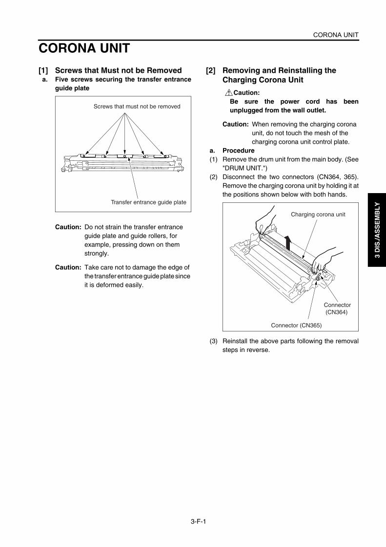
CORONA UNIT
3-F-1
3 D
IS./A
SS
EM
BL
Y
CORONA UNIT
[1] Screws that Must not be Removeda. Five screws securing the transfer entrance
guide plate
Caution: Do not strain the transfer entrance guide plate and guide rollers, for example, pressing down on them strongly.
Caution: Take care not to damage the edge of the transfer entrance guide plate since it is deformed easily.
[2] Removing and Reinstalling the Charging Corona Unit
Caution:Be sure the power cord has beenunplugged from the wall outlet.
Caution: When removing the charging corona unit, do not touch the mesh of the charging corona unit control plate.
a. Procedure(1) Remove the drum unit from the main body. (See
"DRUM UNIT.")(2) Disconnect the two connectors (CN364, 365).
Remove the charging corona unit by holding it atthe positions shown below with both hands.
(3) Reinstall the above parts following the removalsteps in reverse.
Transfer entrance guide plate
Screws that must not be removed
Charging corona unit
Connector (CN365)
Connector (CN364)

CORONA UNIT
3-F-2
3 D
IS./A
SS
EM
BL
Y
[3] Removing and Reinstalling the Charge Control Plate
Caution:Be sure the power cord has beenunplugged from the wall outlet.
a. Procedure(1) Remove the charging corona unit.(2) Remove the two springs and remove the charge
control plate.
(3) Reinstall the above parts following the removalsteps in reverse.
[4] Replacing the Charging Wires
Caution:Be sure the power cord has beenunplugged from the wall outlet.
a. Procedure(1) Remove the charging corona unit.(2) Remove the charge control plate.
(3) Remove the spark arrester plates (front andrear).
(4) Remove the charge control plate cleaner.(5) Remove the spring and remove the charging
wire.
(6) Reinstall the above parts following the removalsteps in reverse.
Charge control plate
Springs
Spark arrester plate (front)
Spark arrester plate (rear)
Charging wireCharge control plate cleaner
Spring
Charging wire

CORONA UNIT
3-F-3
3 D
IS./A
SS
EM
BL
Y
[5] Removing and Reinstalling the Charging Wire Cleaning Unit
Caution:Be sure the power cord has beenunplugged from the wall outlet.
a. Procedure(1) Remove the charging wire.(2) Remove the stop ring and remove the charging
wire cleaning pad.Caution1: When removing the charging wire
cleaning pad, be careful not to dropthe two collars.
Caution2: When installing the charging wirecleaning pad, install the pad in theorientation shown below. Also, donot forget to attach the two collars.
(3) Reinstall the above parts following the removalsteps in reverse.
[6] Removing and Reinstalling the PCL
Caution:Be sure the power cord has beenunplugged from the wall outlet.
a. Procedure(1) Remove the charging corona unit.(2) Disconnect the wire binding band at two loca-
tions.(3) Release the lock and remove the PCL.
Stop ring
Collar
Collar
Charging wire cleaning pad
Charging wire cleaning pad
PCL
PCL
PCL
1
2
Lock
Wire binding band

CORONA UNIT
3-F-4
3 D
IS./A
SS
EM
BL
Y
(4) Reinstall the above parts following the removalsteps in reverse.
Caution: When the urethane sheet is peeled off from PCL, be sure to paste it again. (Di5510/Di7210)
7272ma3008
Urethane sheet
Charging corona unitPCL
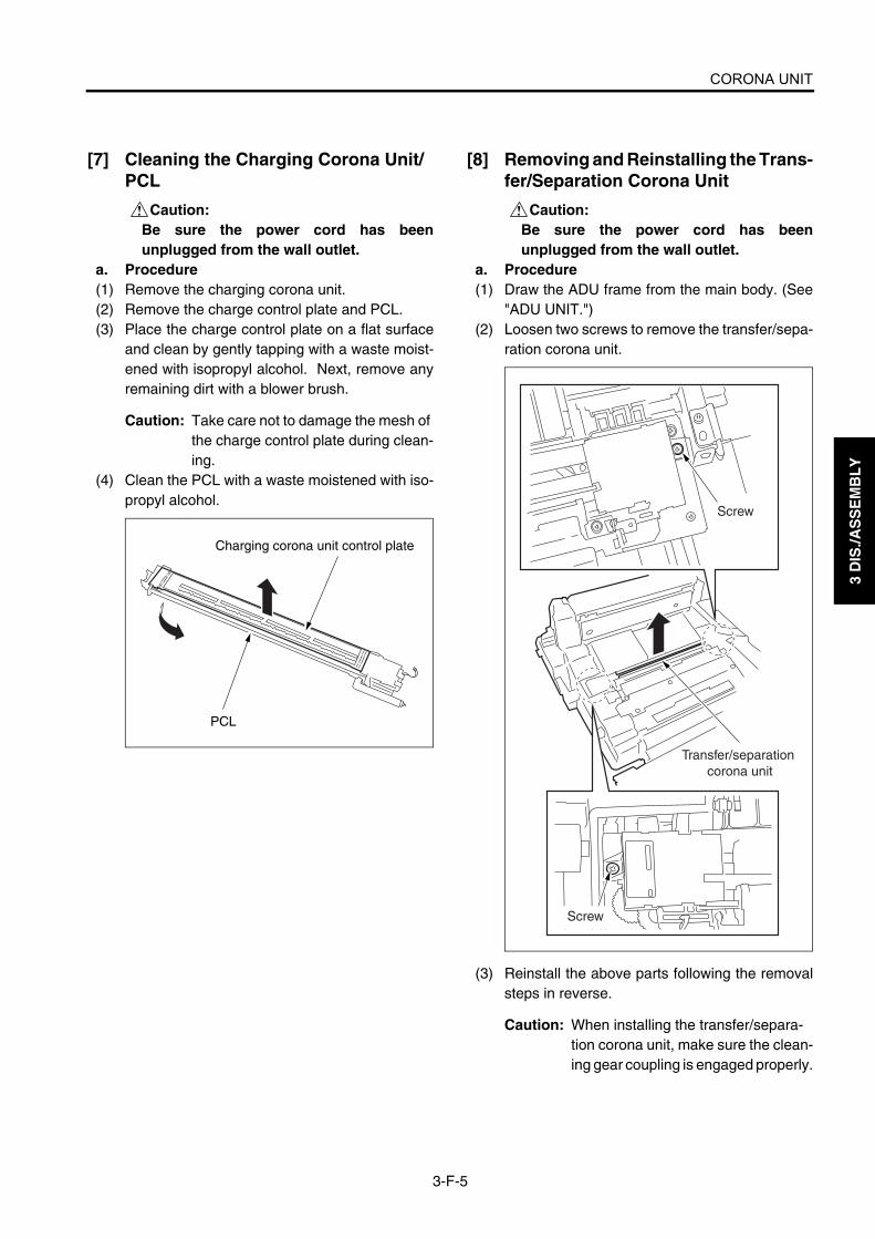
CORONA UNIT
3-F-5
3 D
IS./A
SS
EM
BL
Y
[7] Cleaning the Charging Corona Unit/PCL
Caution:Be sure the power cord has beenunplugged from the wall outlet.
a. Procedure(1) Remove the charging corona unit.(2) Remove the charge control plate and PCL.(3) Place the charge control plate on a flat surface
and clean by gently tapping with a waste moist-ened with isopropyl alcohol. Next, remove anyremaining dirt with a blower brush.
Caution: Take care not to damage the mesh of the charge control plate during clean-ing.
(4) Clean the PCL with a waste moistened with iso-propyl alcohol.
[8] Removing and Reinstalling the Trans-fer/Separation Corona Unit
Caution:Be sure the power cord has beenunplugged from the wall outlet.
a. Procedure(1) Draw the ADU frame from the main body. (See
"ADU UNIT.")(2) Loosen two screws to remove the transfer/sepa-
ration corona unit.
(3) Reinstall the above parts following the removalsteps in reverse.
Caution: When installing the transfer/separa-tion corona unit, make sure the clean-ing gear coupling is engaged properly.
PCL
Charging corona unit control plate
Screw
Screw
Transfer/separation corona unit

CORONA UNIT
3-F-6
3 D
IS./A
SS
EM
BL
Y
[9] Removing and Reinstalling the Plunger Prevention Plate
Caution:Be sure the power cord has beenunplugged from the wall outlet.
a. Procedure(1) Draw the ADU frame from the main body. (See
"ADU UNIT.")(2) Remove the transfer/separation corona unit.(3) Release the six locks and remove the plunger
prevention plate (front).(4) Release the six locks and remove the plunger
prevention plate (rear).
(5) Reinstall the above parts following the removalsteps in reverse.
[10] Replacing the Transfer/Separation Wires and Transfer/Separation Wire Cleaning Block
Caution:Be sure the power cord has beenunplugged from the wall outlet.
a. Procedure(1) Draw the ADU frame from the main body. (See
"ADU UNIT.")(2) Remove the transfer/separation corona unit.(3) Remove the plunger prevention plate.(4) Remove the spark arrester plates (front and
rear).
(5) Remove the springs of wires (one each).
Caution: When installing the springs, bend the edge of each spring inside.
plunger prevention plate (front)
plunger prevention plate (rear)
Lock
Lock
Lock
(Same as on the opposite side)
Spark arrester plate (rear)
Spark arrester plate (front)

CORONA UNIT
3-F-7
3 D
IS./A
SS
EM
BL
Y
(6) Release and remove three wires from eachcleaning block.
Caution: Be careful not to drop and lose the support rubber when removing the wire.
(7) Turn the transfer/separation corona unit upsidedown, remove the stop rings, and remove thetransfer wire cleaning block and separation wirecleaning block from the front side.
(8) Reinstall the above parts following the removalsteps in reverse.
Caution: When installing the transfer/separa-tion wires, check that the coupling of the cleaning pad drive gear is engaged correctly.
Transfer wire
Transfer wire
Separation wire
Support rubber
Spring
Separation wire
Stop rings
Coupling
Transfer wirecleaning block
Separation wire cleaning block

CORONA UNIT
3-F-8
3 D
IS./A
SS
EM
BL
Y
[11] Removing and Reinstalling the TSL Unit
Caution:Be sure the power cord has beenunplugged from the wall outlet.
a. Procedure(1) Draw the ADU frame from the main body. (See
"ADU UNIT.")(2) Remove the transfer/separation corona unit.(3) Remove the relay connector (CN463).
Caution: A relay connector consists of two male sides and one female side. Be sure to remove only the male side (shown below) of the CN463 connector.
(4) Remove the three screws and remove the TSLunit.
(5) Reinstall the above parts following the removalsteps in reverse.
7272ma3034
TSL unit Relay connector (CN463)
Screws
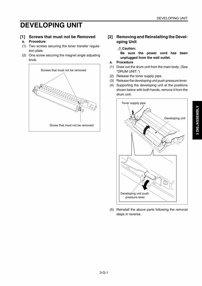
DEVELOPING UNIT
3-G-1
3 D
IS./A
SS
EM
BL
Y
DEVELOPING UNIT
[1] Screws that must not be Removeda. Procedure(1) Two screws securing the toner transfer regula-
tion plate.(2) One screw securing the magnet angle adjusting
knob.
[2] Removing and Reinstalling the Devel-oping Unit
Caution:Be sure the power cord has beenunplugged from the wall outlet.
a. Procedure(1) Draw out the drum unit from the main body. (See
"DRUM UNIT.")(2) Release the toner supply pipe.(3) Release the developing unit push pressure lever.(4) Supporting the developing unit at the positions
shown below with both hands, remove it from thedrum unit.
(5) Reinstall the above parts following the removalsteps in reverse.
Screws that must not be removed
Screw that must not be removed
Toner supply pipe
Developing unit
Developing unit push pressure lever

DEVELOPING UNIT
3-G-2
3 D
IS./A
SS
EM
BL
Y
[3] Replacing the DeveloperCaution1: When replacing the developer in the
developing unit, take care not toallow dirt to get into it.
Caution2: To rotate the developing sleeve,rotate the developing gear counter-clockwise.
Caution3: Never rotate the developing gearclockwise.
Caution4: When installing a new developer, besure to enter mode 25 and select"Copy Count by Parts to beReplaced" to reset developercounter.
a. Procedure(1) Draw out the drum unit from the main body. (See
"DRUM UNIT.")(2) Remove the developing unit from the drum unit.(3) Release the hook of the developing unit cover
and remove it upward.
(4) Tilt the developing unit about 45° and rotate thedeveloping gear counterclockwise to dischargeall of the developer adhering to the inside of thedeveloping unit and magnet roller.
(5) Supply fresh developer evenly from the top of theagitator screws.
(6) Rotate the developing gear until the developerenters the developing unit.
(7) Repeat steps (5) and (6) to supply all of thedeveloper.
Developing gear
Developing unit cover
Hooks
Hooks(Same as
on the opposite side)
45˚
Developing gear
Developer
Developing unit stopper roller

DEVELOPING UNIT
3-G-3
3 D
IS./A
SS
EM
BL
Y
(8) Rotate the developing gear counterclockwise tocheck that the developer bristles along the entirelength of the developing sleeve.
(9) Install the developing unit cover, then install thedeveloping unit in the drum unit.
Caution: After installing the developing unit in the drum unit, make sure the develop-ing unit stopper roller is in contact with the developing unit stopper plate (allo-cation of DSD).
[4] Cleaning the Developing Unit Bias shaft
Caution:Be sure the power cord has beenunplugged from the wall outlet.
a. Procedure(1) Draw out the drum unit from the main body. (See
"DRUM UNIT.")(2) Remove the developing unit from the drum unit.(3) Wipe the dirt on the developing unit bias shaft
with waste.
(4) Reinstall the above parts following the removalsteps in reverse.
Developing sleeve
Developing unit stopper roller
Developing gear
Developing gear
Developing unit bias shaft Developing sleeve

3 D
IS./A
SS
EM
BL
Y
Blank page

TONER SUPPLY UNIT
3-H-1
3 D
IS./A
SS
EM
BL
Y
TONER SUPPLY UNIT
[1] Replacing and Cleaning the Toner Cartridge
a. Procedure(1) Open the toner supply door and pull the toner
supply unit forward.
(2) Remove the toner cartridge.(3) After removing the toner cartridge, clean the
area around the toner cartridge insertion holewith a waste.
(4) Reinstall the above parts following the removalsteps in reverse.
Toner supply door
Toner supply unit
Toner cartridge
Cartridge insertion hole

3 D
IS./A
SS
EM
BL
Y
Blank page
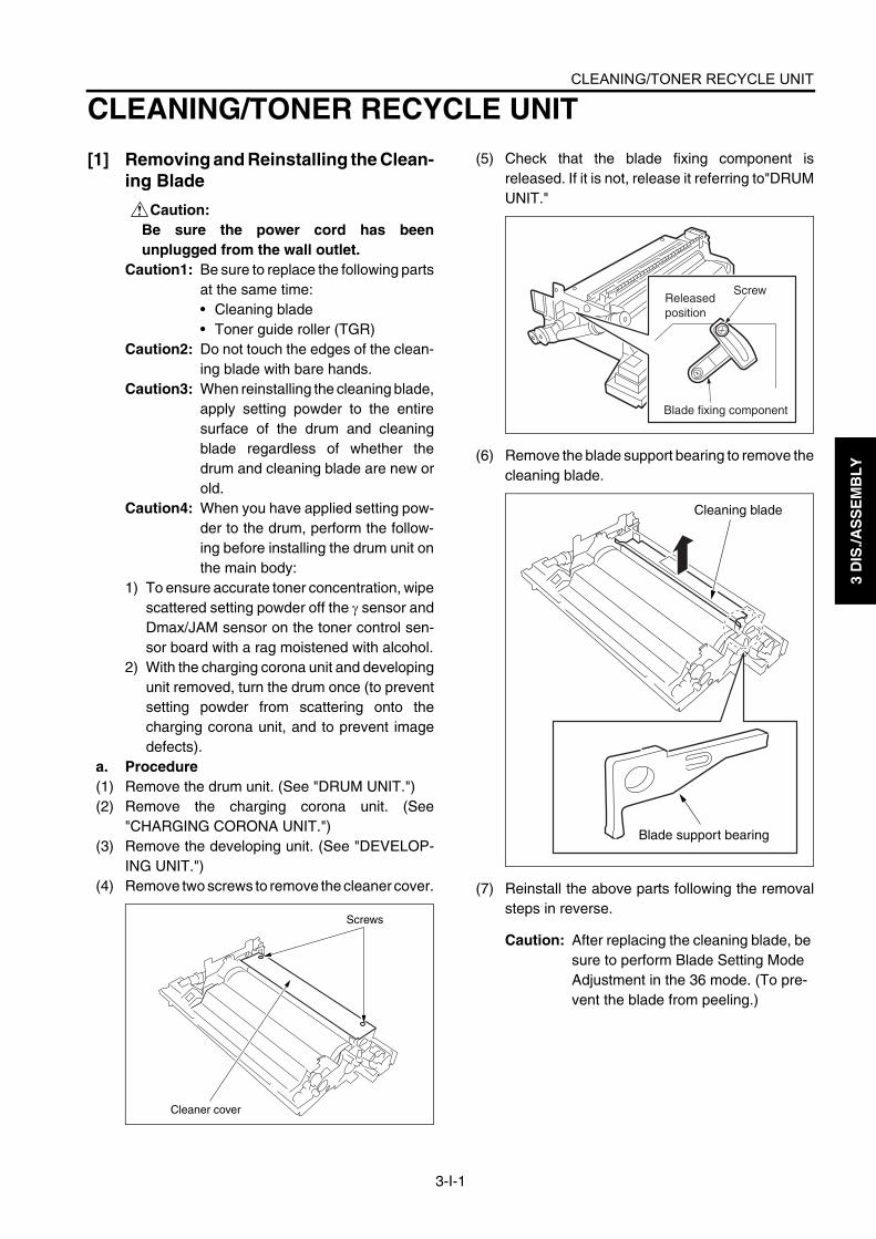
CLEANING/TONER RECYCLE UNIT
3-I-1
3 D
IS./A
SS
EM
BL
Y
CLEANING/TONER RECYCLE UNIT
[1] Removing and Reinstalling the Clean-ing Blade
Caution:Be sure the power cord has beenunplugged from the wall outlet.
Caution1: Be sure to replace the following partsat the same time:• Cleaning blade• Toner guide roller (TGR)
Caution2: Do not touch the edges of the clean-ing blade with bare hands.
Caution3: When reinstalling the cleaning blade,apply setting powder to the entiresurface of the drum and cleaningblade regardless of whether thedrum and cleaning blade are new orold.
Caution4: When you have applied setting pow-der to the drum, perform the follow-ing before installing the drum unit onthe main body:
1) To ensure accurate toner concentration, wipescattered setting powder off the γ sensor andDmax/JAM sensor on the toner control sen-sor board with a rag moistened with alcohol.
2) With the charging corona unit and developingunit removed, turn the drum once (to preventsetting powder from scattering onto thecharging corona unit, and to prevent imagedefects).
a. Procedure(1) Remove the drum unit. (See "DRUM UNIT.")(2) Remove the charging corona unit. (See
"CHARGING CORONA UNIT.")(3) Remove the developing unit. (See "DEVELOP-
ING UNIT.")(4) Remove two screws to remove the cleaner cover.
(5) Check that the blade fixing component isreleased. If it is not, release it referring to"DRUMUNIT."
(6) Remove the blade support bearing to remove thecleaning blade.
(7) Reinstall the above parts following the removalsteps in reverse.
Caution: After replacing the cleaning blade, be sure to perform Blade Setting Mode Adjustment in the 36 mode. (To pre-vent the blade from peeling.)
Screws
Cleaner cover
ScrewReleased position
Blade fixing component
Cleaning blade
Blade support bearing

CLEANING/TONER RECYCLE UNIT
3-I-2
3 D
IS./A
SS
EM
BL
Y
[2] Removing and Reinstalling the Toner Guide Roller (TGR)
Caution:Be sure the power cord has beenunplugged from the wall outlet.
Caution1: Be sure to replace the following partsat the same time:• Cleaning blade• Toner guide roller
Caution2: Do not touch the edges of the clean-ing blade with bare hands.
Caution3: When reinstalling the cleaning blade,apply setting powder to the entiresurface of the drum and cleaningblade regardless of whether theparts are new or old.
Caution4: When reinstalling the toner guideroller, apply setting powder to thetoner guide roller evenly. Apply withthe toner guide roller removed fromthe drum unit.
Caution5: Do not touch the toner guide rollerbrush with bare hands. Also, do notdirectly contact the rollers to anyobject.
Caution6: After replacing the toner guide roller,be sure to apply electricity lubricanton the edge of the guide roller shaft(on power supply pin side).
Caution7: When installing a toner guide roller,be sure to enter mode 25 and select"Copy Count by Parts to beReplaced" to reset toner collectionroller assembly counter.
a. Procedure(1) Remove the drum unit. (See "DRUM UNIT.")(2) Remove the charging corona unit. (See
"CHARGING CORONA UNIT.")(3) Remove the cleaning blade.(4) Release the power supply pin in contact with the
toner guide roller shaft.(5) Remove the stop ring. (6) Remove the cleaner idle gear.(7) Remove the screws securing the front and rear
positioning parts.
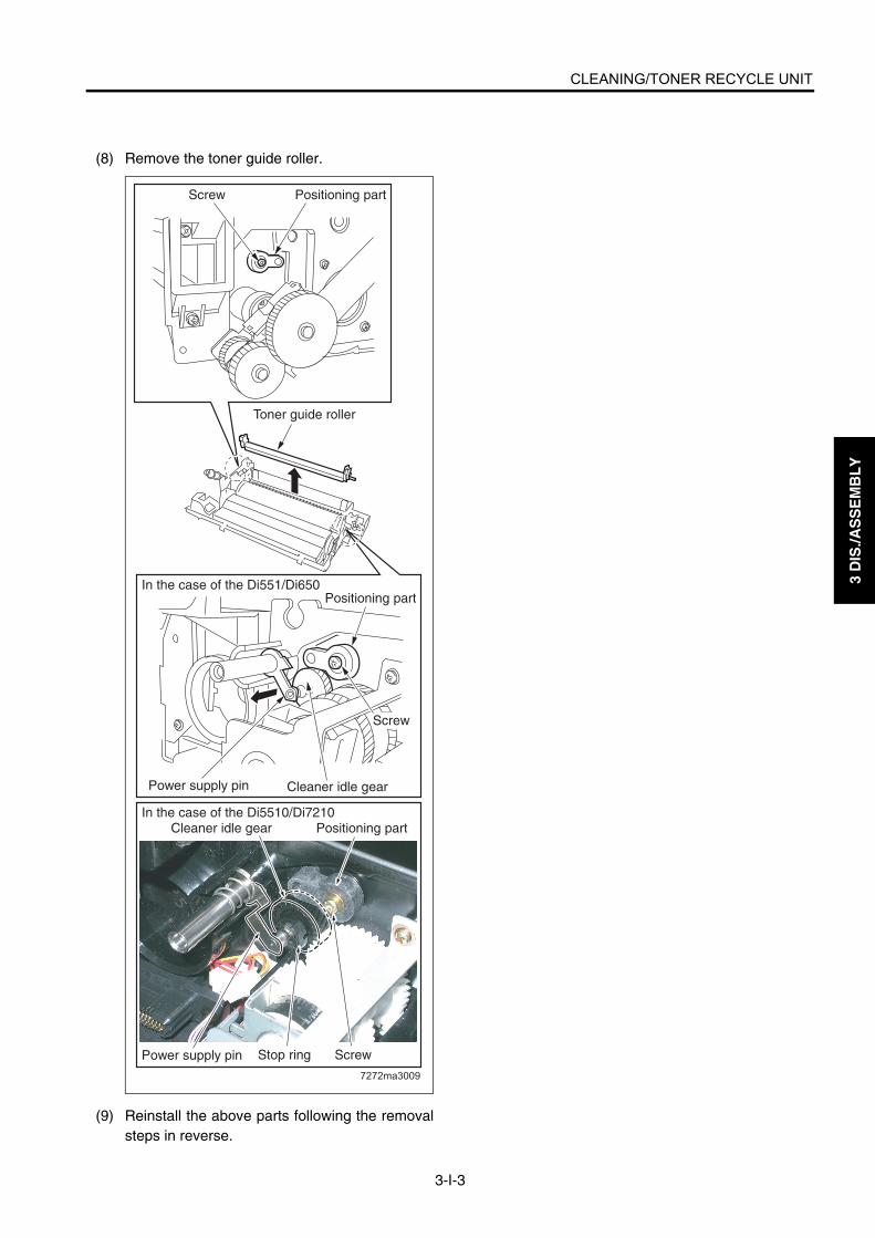
CLEANING/TONER RECYCLE UNIT
3-I-3
3 D
IS./A
SS
EM
BL
Y
(8) Remove the toner guide roller.
(9) Reinstall the above parts following the removalsteps in reverse.
7272ma3009
Power supply pin Cleaner idle gear
Screw
Positioning part
In the case of the Di5510/Di7210
Positioning part
Screw
Power supply pin
Positioning partCleaner idle gear
Stop ring Screw
In the case of the Di551/Di650
Toner guide roller

3 D
IS./A
SS
EM
BL
Y
Blank page

PAPER FEED UNITS OF TRAYS 1 AND 2 (Di551/Di650)
3-J-1
3 D
IS./A
SS
EM
BL
Y
PAPER FEED UNITS OF TRAYS 1 AND 2 (Di551/Di650)
[1] Removing and Reinstalling the Paper Feed Unit
Caution:Be sure the power cord has beenunplugged from the wall outlet.
a. Procedure(1) Draw out paper feed tray 1 or 2.(2) Loosen the securing shaft screw, and remove
one screw.(3) Disconnect the relay connector (CN814, 834)
and remove the paper feed unit by lifting.
(4) Reinstall the above parts following the removalsteps in reverse.
[2] Removing and Reinstalling the Paper Feed Trays 1 and 2
Warning:When removing the tray, stand in a properposition so that you do not hurt your backand waist. If the tray contains paper,remove all paper before removing the tray.
Caution:Be sure the power cord has beenunplugged from the wall outlet.
a. Procedure(1) Draw out paper feed tray 1 or 2.(2) Remove the paper feed unit.(3) Remove four screws and remove tray 1 or 2 by
lifting.
(4) Reinstall the above parts following the removalsteps in reverse.
Relay connector (CN814, 834)
Securing shaft screw
Paper feed unit
Screw
Tray 1,2
Screws

PAPER FEED UNITS OF TRAYS 1 AND 2 (Di551/Di650)
3-J-2
3 D
IS./A
SS
EM
BL
Y
[3] Removing and Reinstalling the Paper Feed Roller and Feed Roller Rubber
a. Procedure(1) Remove the paper feed unit.(2) Remove the two stop rings and slide the two
bearings outward.(3) Release the feed roller axis from the holder slit to
detach the paper feed roller unit.
(4) Remove the two stop rings from the paper feedroller unit to detach the paper feed roller and feedroller.
(5) Remove the rubber from each roller.
(6) Reinstall the above parts following the removalsteps in reverse.Caution1: When reinstalling the rollers, pay
attention to their orientation.Caution2: Check that no grease or the like
remains on each roller.
[4] Removing and Reinstalling the Dou-ble Feed Prevention Roller Rubber
a. Procedure(1) Remove the paper feed unit.(2) Remove the paper feed roller unit.(3) Remove the stop ring to detach the double feed
prevention roller.(4) Remove the double feed prevention roller rubber
from the roller.
(5) Reinstall the above parts following the removalsteps in reverse.Caution1: When reinstalling the double feed
prevention roller, pay attention totheir orientation.
Caution2: Check that no grease or the likeremains on the double feed preven-tion roller.
Slit
Stop ring
Stop ringBearing
Paper feed roller unit
Bearing
Feed roller
Feed roller rubber Stop rings
Paint mark
Paper feed roller
Paper feed roller rubber
Paint mark
Double feed prevention roller
Double feed prevention roller rubber
Stop ring
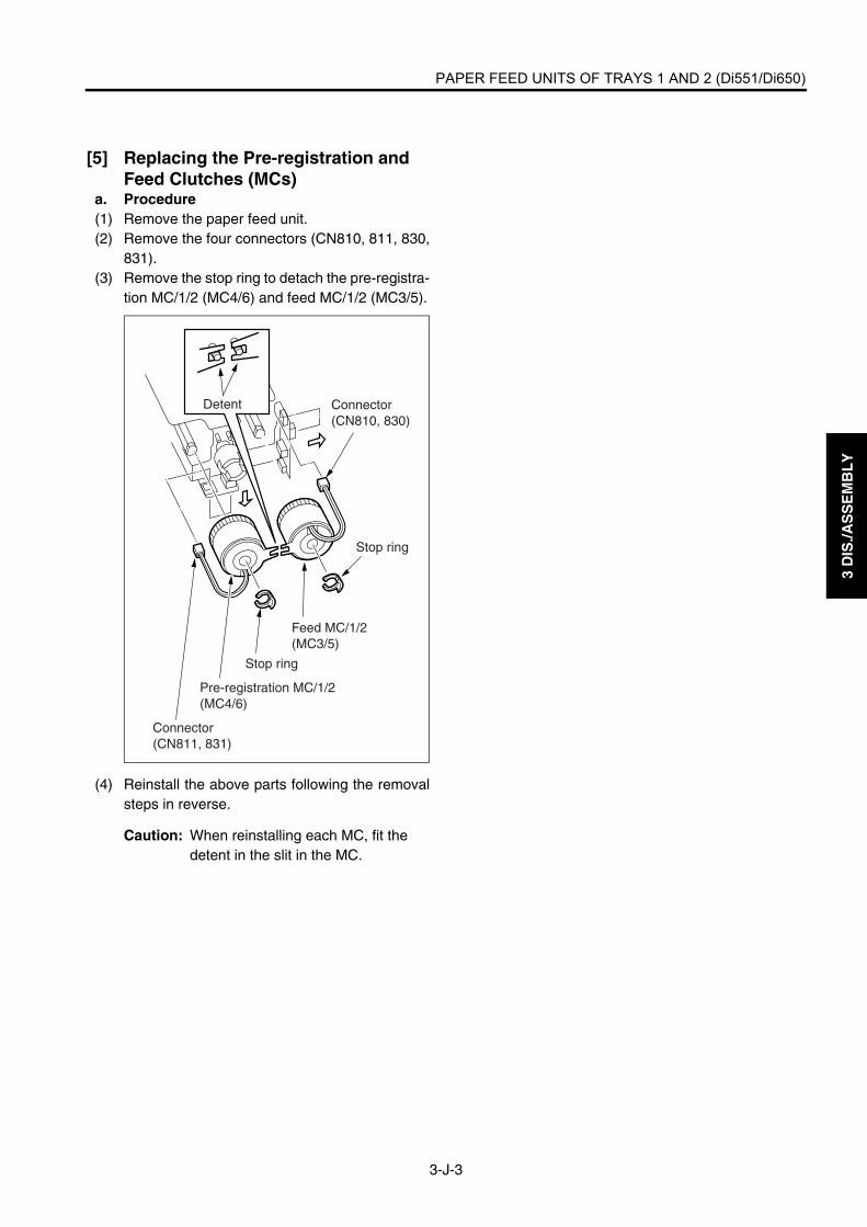
PAPER FEED UNITS OF TRAYS 1 AND 2 (Di551/Di650)
3-J-3
3 D
IS./A
SS
EM
BL
Y
[5] Replacing the Pre-registration and Feed Clutches (MCs)
a. Procedure(1) Remove the paper feed unit.(2) Remove the four connectors (CN810, 811, 830,
831).(3) Remove the stop ring to detach the pre-registra-
tion MC/1/2 (MC4/6) and feed MC/1/2 (MC3/5).
(4) Reinstall the above parts following the removalsteps in reverse.
Caution: When reinstalling each MC, fit the detent in the slit in the MC.
Connector(CN810, 830)
Connector(CN811, 831)
Pre-registration MC/1/2(MC4/6)
Feed MC/1/2(MC3/5)
Stop ring
Detent
Stop ring

PAPER FEED UNITS OF TRAYS 1 AND 2 (Di551/Di650)
3-J-4
3 D
IS./A
SS
EM
BL
Y
[6] Replacing the WiresCaution1: After replacing or reinstalling the wires, manually rotate the up/down drive shaft to check that the
tray moves up and down smoothly.Caution2: Be sure to install the wires so that they do not cross or ride over each other.
<Removing Wires>(1) Remove the paper feed unit.(2) Remove three screws to remove the wire cover(front) and wire cover (rear).
Wire cover (rear)
Wire cover (front)
Screws (6)

PAPER FEED UNITS OF TRAYS 1 AND 2 (Di551/Di650)
3-J-5
3 D
IS./A
SS
EM
BL
Y
(3) Remove the front and rear wires according to steps 1 to 7 below.
Drive pulley
Drive pulley holder
2, 4 Remove the E-ring to detach the wire restraining cover and pulley.
Wire restraining cover
Pulley
E-ring
1 Remove the E-ring to slide out the drive pulley.
Wire C (black)
Wire D (white)
Drive pulley
E-ring
Wire C (black)
Wire D (white)
3. Remove wire C.
5. Remove wire D.
Up/down plate
Wire B (white)
Wire C (black)
Wire A (black)
7. Repeat steps 2 to 5 to remove wire A and wire B.
6. Remove drive pulley holder and E-ring and pull out the drive pulley.
Wire B (white)
Wire A(black)
E-ring
Wire D (White)

PAPER FEED UNITS OF TRAYS 1 AND 2 (Di551/Di650)
3-J-6
3 D
IS./A
SS
EM
BL
Y
<Wire Lengths>
<Installing Wires>
Wire A, C
Wire B, D
182.8±1 mm (Tray 1, 2)
473.1±1 mm (Tray 1, 2)
2. Install the pulley, pass wire D through the pulley, and install the wire restraining cover and E-ring.
Wire restraining cover
Pulley
E-ring
Wire C (black)Wire D
(white)
5. Install the wires C and D from inside the drive shaft hole, push in the drive pulley, and secure with E-ring.
4. Install the pulley, pass wires C and D, and install the wire restraining cover and retaining ring. Wire D must be inside. Wires must not cross.
Wire C (black)
Wire D (white)
E-ring
7. Install the wires A and B from inside the drive shaft hole, push in the drive pulley, and secure with E-ring. Next, install the drive pulley holder.
Wire A (black)Wire B
(white)Drive pulley holder
Drive pulleyE-ring
Wire A (black)
Wire B (white)
Up/down plate
1. Pass wire D through the up/down plate.
3. Pass wire C through the up/down plate.
Wire C (black)
Wire D (white)
6. Repeat steps 1 to 4 to install wire A and wire B.

PAPER FEED UNITS OF TRAYS 1 AND 2 (Di5510/Di7210)
3-J-7
3 D
IS./A
SS
EM
BL
Y
PAPER FEED UNITS OF TRAYS 1 AND 2 (Di5510/Di7210)
Caution:Trays 1 and 2 have the same shape andmechanism.
[1] Removing and Reinstalling the Paper Feed UnitThe contents here shall be in accordance withthe "[1] Removing and Reinstalling the PaperFeed Unit" of PAPER FEED UNITS OF TRAY 1and 2 (Di551/Di650).
[2] Removing and Reinstalling the Paper Feed Tray 1
Warning:When removing the tray, stand in a properposition so that you do not hurt your backand waist. If the tray contains paper,remove all paper before removing the tray.
Caution:Be sure the power cord has beenunplugged from the wall outlet.
a. Procedure(1) Draw out paper feed tray 1.(2) Remove the paper feed unit.(3) Remove four screws and remove the LCT cover
/L.
7272ma3010
LCT cover /L
Screws
Screws
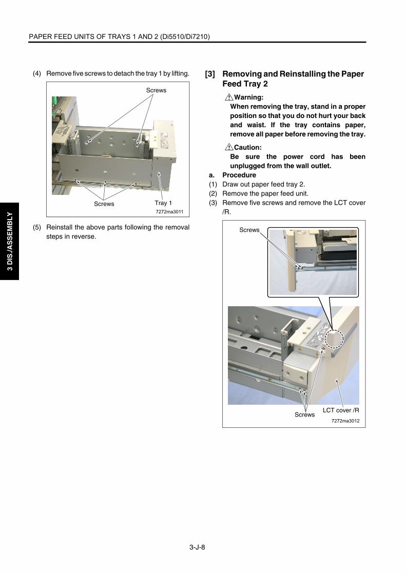
PAPER FEED UNITS OF TRAYS 1 AND 2 (Di5510/Di7210)
3-J-8
3 D
IS./A
SS
EM
BL
Y
(4) Remove five screws to detach the tray 1 by lifting.
(5) Reinstall the above parts following the removalsteps in reverse.
[3] Removing and Reinstalling the Paper Feed Tray 2
Warning:When removing the tray, stand in a properposition so that you do not hurt your backand waist. If the tray contains paper,remove all paper before removing the tray.
Caution:Be sure the power cord has beenunplugged from the wall outlet.
a. Procedure(1) Draw out paper feed tray 2.(2) Remove the paper feed unit.(3) Remove five screws and remove the LCT cover
/R.7272ma3011
Screws
Screws
Tray 1
7272ma3012
Screws
ScrewsLCT cover /R

PAPER FEED UNITS OF TRAYS 1 AND 2 (Di5510/Di7210)
3-J-9
3 D
IS./A
SS
EM
BL
Y
(4) Remove five screws to detach the tray 2 by lifting.
(5) Reinstall the above parts following the removalsteps in reverse.
[4] Removing and Reinstalling the Paper Feed Roller and Feed Roller Rubber
a. Procedure(1) Remove the paper feed unit.(2) Remove the two stop rings and slide the two
bearings outward.(3) Release the feed roller axis from the holder slit to
detach the paper feed roller unit.
(4) Remove the two stop rings from the paper feedroller unit to detach the paper feed roller and feedroller.
7272ma3013
Screws
Screws
Tray 2
Slit
Stop ring
Stop ringBearing
Paper feed roller unit
Bearing

PAPER FEED UNITS OF TRAYS 1 AND 2 (Di5510/Di7210)
3-J-10
3 D
IS./A
SS
EM
BL
Y
(5) Remove the rubber from each roller.
(6) Reinstall the above parts following the removalsteps in reverse.Caution1: When reinstalling the rollers, pay
attention to their orientation.Caution2: Check that no grease or the like
remains on each roller.
[5] Removing and Reinstalling the Dou-ble Feed Prevention Roller RubberThe contents here shall be in accordance withthe "[4] Removing and Reinstalling the DoubleFeed Prevention Roller Rubber" of PAPER FEEDUNITS OF TRAY 1 AND 2 (Di551/Di650).
7272ma3014
Stop ring
Feed roller rubber
Paper feed roller rubber Paint mark
Feed roller
Paper feed rollerPaint mark
Arrow mark

PAPER FEED UNITS OF TRAYS 1 AND 2 (Di5510/Di7210)
3-J-11
3 D
IS./A
SS
EM
BL
Y
[6] Replacing the Pre-registration and Feed Clutches (MCs)The contents here shall be in accordance withthe "[5] Replacing the Pre-registration and FeedClutches (MCs)" of PAPER FEED UNITS OFTRAY 1 and 2 (Di551/Di650).
[7] Replacing the Horizontal Conveyance MC/L and /R
a. Procedure(1) Remove the vertical conveyance section. (See
"VERTICAL CONVEYNACE SECTION")(2) Draw out the horizontal conveyance section and
tray 2.(3) Remove two relay connectors (CN902, 903).(4) Remove a screw to detach the sensor mounting
plate.(5) Remove a stop ring for each, detach the horizon-
tal conveyance MC/L (MC15) and horizontal con-veyance MC/R (MC16).
(6) Reinstall the above parts following the removalsteps in reverse.
Caution: When installing, align the projections with the detent guides.
7272ma3015
Sensor mountingplate
Horizontal conveyanceMC/R (MC16)
Detent
Stop ring
Relay connector (CN903)
Relay connector (CN902)
Horizontal conveyance MC/L (MC15)
Screw

PAPER FEED UNITS OF TRAYS 1 AND 2 (Di5510/Di7210)
3-J-12
3 D
IS./A
SS
EM
BL
Y
[8] Replacing the WiresCaution1: After replacing or reinstalling the wires, manually rotate the up/down drive shaft to check that the
tray moves up and down smoothly.Caution2: Be sure to install the wires so that they do not cross or ride over each other.
<Removing Wires>(1) Remove the paper feed unit.(2) Remove two screws for each to remove the wire cover (front) and wire cover (rear).
7272ma3016Screws
ScrewsWire cover (rear)
Wire cover (front)

PAPER FEED UNITS OF TRAYS 1 AND 2 (Di5510/Di7210)
3-J-13
3 D
IS./A
SS
EM
BL
Y
(3) Remove the wires A and B according to steps 1 to 10 of the figure below.
7272ma3017
Wire restraining cover
PulleyWire B (White)
E-ring
4. Remove the E-ring.5. Remove the pulley and wire restraining cover to release the wire A (black) and B(white).
6. Remove the E-ring.7. Remove the pulley and wire restraining cover to release the wire B (white).
3. Remove the E-ring, slide the drive pulley in ward, and remove the wire B (white) from the drive shaft.
1. Remove the E-ring and bearing to detach the gear assembly.
2. Remove the bearing.9. Remove the E-ring, slide the drive pulley outward, and remove the wire A (black) from the drive shaft.
8. Pull out and remove the wire B (white) toward the bottom side of the up/down plate.10. Pull out and remove the wire B (white) toward the bottom side of the up/down plate.
Wire restraining coverPulley
Wire A (Black)
Wire B (White)
E-ring
Drive shaftDrive pulleyWire A (Black)
Wire B (White)E-ring
Gear assembly Bearing E-ring
BearingDrive shaftE-ringDrive pulley
Wire A (Black)
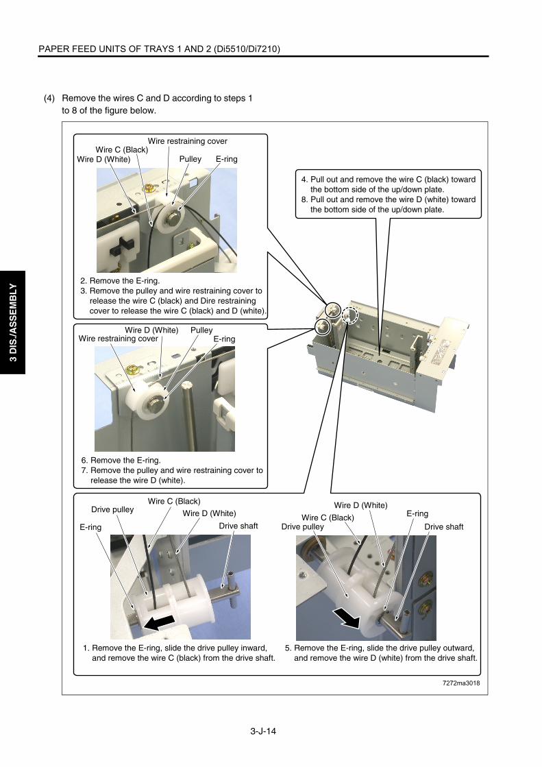
PAPER FEED UNITS OF TRAYS 1 AND 2 (Di5510/Di7210)
3-J-14
3 D
IS./A
SS
EM
BL
Y
(4) Remove the wires C and D according to steps 1to 8 of the figure below.
7272ma3018
6. Remove the E-ring.7. Remove the pulley and wire restraining cover to release the wire D (white).
1. Remove the E-ring, slide the drive pulley inward, and remove the wire C (black) from the drive shaft.
5. Remove the E-ring, slide the drive pulley outward, and remove the wire D (white) from the drive shaft.
4. Pull out and remove the wire C (black) toward the bottom side of the up/down plate.8. Pull out and remove the wire D (white) toward the bottom side of the up/down plate.
Wire restraining cover
PulleyWire C (Black)
Wire D (White) E-ring
Wire restraining coverWire D (White)
E-ring
E-ring
E-ring
2. Remove the E-ring.3. Remove the pulley and wire restraining cover to release the wire C (black) and Dire restraining cover to release the wire C (black) and D (white).
Drive pulley
Drive shaft
Wire C (Black)
Wire D (White)
Drive pulley Drive shaftWire C (Black)
Wire D (White)
Pulley

PAPER FEED UNITS OF TRAYS 1 AND 2 (Di5510/Di7210)
3-J-15
3 D
IS./A
SS
EM
BL
Y
<Wire Lengths>
<Installing Wires>Reinstall the wires following the removal steps inreverse.
7272ma3019
294.8 1mm(Tray 1)232.4 1mm(Tray 2)
391.7 1mm(Tray 1)329.2 1mm(Tray 2)
Wire A, C
Wire B, D

3 D
IS./A
SS
EM
BL
Y
Blank page
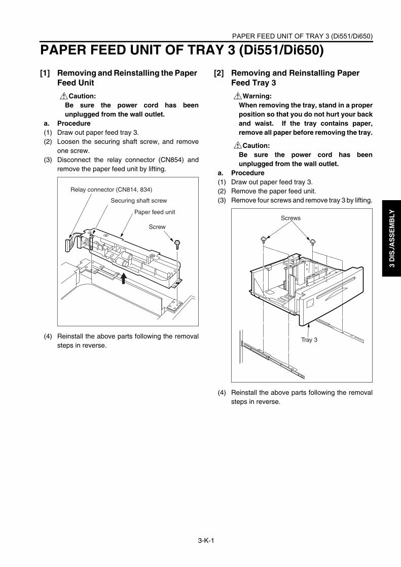
PAPER FEED UNIT OF TRAY 3 (Di551/Di650)
3-K-1
3 D
IS./A
SS
EM
BL
Y
PAPER FEED UNIT OF TRAY 3 (Di551/Di650)
[1] Removing and Reinstalling the Paper Feed Unit
Caution:Be sure the power cord has beenunplugged from the wall outlet.
a. Procedure(1) Draw out paper feed tray 3.(2) Loosen the securing shaft screw, and remove
one screw.(3) Disconnect the relay connector (CN854) and
remove the paper feed unit by lifting.
(4) Reinstall the above parts following the removalsteps in reverse.
[2] Removing and Reinstalling Paper Feed Tray 3
Warning:When removing the tray, stand in a properposition so that you do not hurt your backand waist. If the tray contains paper,remove all paper before removing the tray.
Caution:Be sure the power cord has beenunplugged from the wall outlet.
a. Procedure(1) Draw out paper feed tray 3.(2) Remove the paper feed unit.(3) Remove four screws and remove tray 3 by lifting.
(4) Reinstall the above parts following the removalsteps in reverse.
Relay connector (CN814, 834)
Securing shaft screw
Paper feed unit
Screw
Tray 3
Screws

PAPER FEED UNIT OF TRAY 3 (Di551/Di650)
3-K-2
3 D
IS./A
SS
EM
BL
Y
[3] Removing and Reinstalling the Paper Feed Roller and Feed Roller Rubber
a. Procedure(1) Remove the paper feed unit.(2) Remove two stop rings and slide the two bear-
ings outward.(3) Release the feed roller axis from the holder slit to
detach the paper feed roller unit.
(4) Remove two stop rings from the paper feed rollerunit to detach the paper feed roller and feedroller.
(5) Remove the rubber from each roller.
(6) Reinstall the above parts following the removalsteps in reverse.Caution1: When reinstalling the rollers, pay
attention to their orientation.Caution2: Check that no grease or the like
remains on each roller.
[4] Removing and Reinstalling the Dou-ble Feed Prevention Roller Rubber
a. Procedure(1) Remove the paper feed unit.(2) Remove the paper feed roller unit.(3) Remove the stop ring to detach the double feed
prevention roller.(4) Remove the double feed prevention roller rubber
from the roller.
(5) Reinstall the above parts following the removalsteps in reverse.Caution1: When reinstalling the double feed
prevention roller, pay attention totheir orientation.
Caution2: Check that no grease or the likeremains on the double feed preven-tion roller.
Slit
Stop ring
Stop ringBearing
Paper feed roller unit
Bearing
Feed roller
Feed roller rubber Stop rings
Paint mark
Paper feed roller
Paper feed roller rubber
Paint mark
Double feed prevention roller
Double feed prevention roller rubber
Stop ring

PAPER FEED UNIT OF TRAY 3 (Di551/Di650)
3-K-3
3 D
IS./A
SS
EM
BL
Y
[5] Replacing the Pre-registration and Feed Clutches (MCs)
a. Procedure(1) Remove the paper feed unit.(2) Remove two connectors (CN850, 851).(3) Remove two stop rings to detach the pre-regis-
tration MC/3 (MC8) and feed MC/3 (MC7).
(4) Reinstall the above parts following the removalsteps in reverse.
Caution: When reinstalling each MC, fit the detent in the slit in the MC.
Connector(CN810, 830)
Connector(CN811, 831)
Pre-registration MC/1/2(MC4/6)
Feed MC/1/2(MC3/5)
Stop ring
Detent
Stop ring
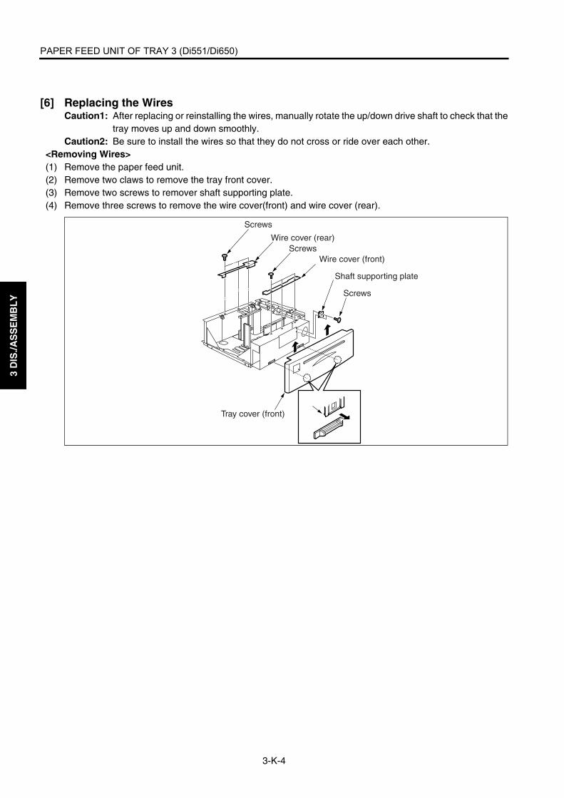
PAPER FEED UNIT OF TRAY 3 (Di551/Di650)
3-K-4
3 D
IS./A
SS
EM
BL
Y
[6] Replacing the WiresCaution1: After replacing or reinstalling the wires, manually rotate the up/down drive shaft to check that the
tray moves up and down smoothly.Caution2: Be sure to install the wires so that they do not cross or ride over each other.
<Removing Wires>(1) Remove the paper feed unit.(2) Remove two claws to remove the tray front cover.(3) Remove two screws to remover shaft supporting plate.(4) Remove three screws to remove the wire cover(front) and wire cover (rear).
Wire cover (rear)
Tray cover (front)
Screws
Screws
Screws
Wire cover (front)
Shaft supporting plate

PAPER FEED UNIT OF TRAY 3 (Di551/Di650)
3-K-5
3 D
IS./A
SS
EM
BL
Y
(5) Remove the front and rear wires according to steps 1 to 7 below.
Drive pulley
2, 4 Remove the E-ring to detach the wire restraining cover and pulley.
Wire restraining cover
Pulley
E-ring
1 Remove two E-rings to slide out the drive pulley.
Wire C (black)
Wire D (white)
Drive pulley
E-ring
E-ring
Wire C (black)
Wire D (white)
3. Remove wire C.
5. Remove wire D.
Up/down plate
Wire B (white)
Wire C (black)
Wire A (black)
7. Repeat steps 2 to 5 to remove wire A and wire B.
6. Remove drive pulley holder and three E-rings and pull out the drive pulley.
Wire B (white)Wire A (black)
E-ring
E-ring
E-ring
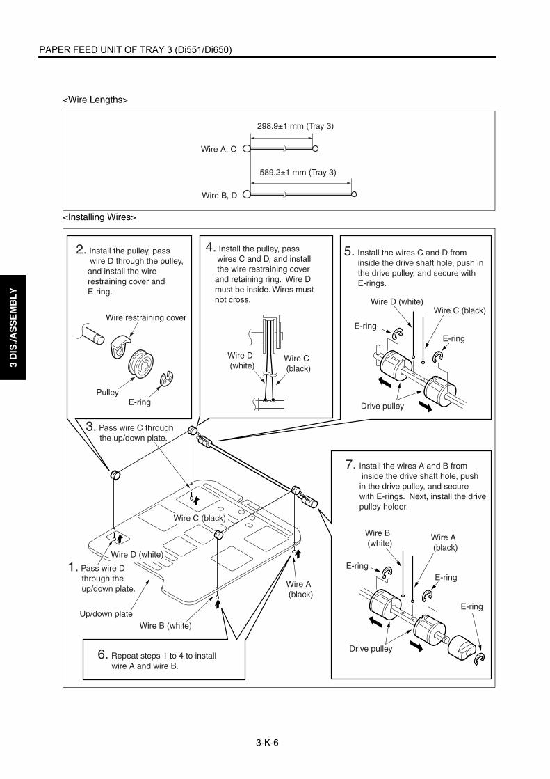
PAPER FEED UNIT OF TRAY 3 (Di551/Di650)
3-K-6
3 D
IS./A
SS
EM
BL
Y
<Wire Lengths>
<Installing Wires>
Wire A, C
Wire B, D
298.9±1 mm (Tray 3)
589.2±1 mm (Tray 3)
2. Install the pulley, pass wire D through the pulley, and install the wire restraining cover and E-ring.
Wire restraining cover
PulleyE-ring
Wire C (black)
Wire D (white)
5. Install the wires C and D from inside the drive shaft hole, push in the drive pulley, and secure with E-rings.
4. Install the pulley, pass wires C and D, and install the wire restraining cover and retaining ring. Wire D must be inside. Wires must not cross.
Wire C (black)Wire D (white)
E-ring
E-ring
7. Install the wires A and B from inside the drive shaft hole, push in the drive pulley, and secure with E-rings. Next, install the drive pulley holder.
Wire A (black)
Wire B (white)
Drive pulley
Drive pulley
E-ringE-ring
E-ring
Wire A (black)
Wire B (white)Up/down plate
1. Pass wire D through the up/down plate.
3. Pass wire C through the up/down plate.
Wire C (black)
Wire D (white)
6. Repeat steps 1 to 4 to install wire A and wire B.

PAPER FEED UNITS OF TRAYS 3 AND 4 (Di5510/Di7210)
3-K-7
3 D
IS./A
SS
EM
BL
Y
PAPER FEED UNITS OF TRAYS 3 AND 4 (Di5510/Di7210)
Caution:Trays 3 and 4 have the same shape andmechanism.
[1] Removing and Reinstalling the Paper Feed UnitThe contents here shall be in accordance withthe "[1] Removing and Reinstalling the PaperFeed Unit" of PAPER FEED UNITS OF TRAY 1AND 2 (Di551/Di650).
[2] Removing and Reinstalling the Paper Feed Tray 3 and 4
Warning:When removing the tray, stand in a properposition so that you do not hurt your backand waist. If the tray contains paper,remove all paper before removing the tray.
Caution:Be sure the power cord has beenunplugged from the wall outlet.
a. Procedure(1) Draw out paper feed tray 3.(2) Remove the paper feed unit.(3) Remove eight screws and detach the tray 3 by
lifting.
(4) Reinstall the above parts following the removalsteps in reverse.
7272ma3020
ScrewsScrews
ScrewsTray 3

PAPER FEED UNITS OF TRAYS 3 AND 4 (Di5510/Di7210)
3-K-8
3 D
IS./A
SS
EM
BL
Y
[3] Removing and Reinstalling the Paper Feed Roller and Feed Roller RubberThe contents here shall be in accordance withthe "[4] Removing and Reinstalling the PaperFeed Roller and Feed Roller Rubber" of PAPERFEED UNITS OF TRAY 1 AND 2 (Di5510/Di7210).
[4] Removing and Reinstalling the Dou-ble Feed Prevention Roller RubberThe contents here shall be in accordance withthe "[4] Removing and Reinstalling the DoubleFeed Prevention Roller Rubber" of PAPER FEEDUNITS OF TRAY 1 AND 2 (Di551/Di650).

PAPER FEED UNITS OF TRAYS 3 AND 4 (Di5510/Di7210)
3-K-9
3 D
IS./A
SS
EM
BL
Y
[5] Replacing the Pre-registration and Feed Clutches (MCs)The contents here shall be in accordance withthe "[5] Replacing the Pre-registration and FeedClutches (MCs)" of PAPER FEED UNITS OFTRAY 1 and 2 (Di551/Di650).
[6] Replacing the WiresThe contents here shall be in accordance withthe "[6] Replacing the Wires" of PAPER FEEDUNITS OF TRAY 1 and 2 (Di551/Di650).

3 D
IS./A
SS
EM
BL
Y
Blank page

BY-PASS FEED TRAY
3-L-1
3 D
IS./A
SS
EM
BL
Y
BY-PASS FEED TRAY
[1] Removing and Reinstalling the by-pass Feed Tray
Caution:Be sure the power cord has beenunplugged from the wall outlet.
a. Procedure(1) Remove the developing suction filter cover and
right side cover (upper). (See "EXTERNAL SEC-TION.")
(2) Remove the connector (CN214).(3) Remove five screws to remove the by-pass feed
tray.
(4) Reinstall the above parts following the removalsteps in reverse.
[2] Replacing the Paper Feed Roller/Paper Feed Roller Rubber
a. Procedure(1) Remove the by-pass feed tray.(2) Remove the stop ring and bearing and pull out
the shaft from the paper feed roller.(3) Remove the two bearings and one gear and
remove the paper feed roller rubber from thepaper feed roller.
(4) Remove the stop ring from the paper feed rollerassembly to pull out the shaft and remove thepaper feed roller rubber from the paper feedroller.
(5) Reinstall the above parts following the removalsteps in reverse.Caution1: Check that the orientation of the
roller is correct when installing.Caution2: Check that no grease or the like
remains on the roller.
7272ma3021
Connector (CN214)
Screws (2)
Screws (2)
By-pass feed tray
Screw
Paper feed rollerGear
Bearing
Stop ring Bearing
Paper feed roller assembly
Paint mark
Shaft
Paper feed roller rubber
Shaft
Stop ring Paper feed roller
Paper feed roller rubber

BY-PASS FEED TRAY
3-L-2
3 D
IS./A
SS
EM
BL
Y
[3] Replacing the Double Feed Preven-tion Roller Rubber
a. Procedure(1) Remove the by-pass feed tray and place the tray
upside down.(2) Remove two screws to remove the bottom plate
assembly.(3) Remove the spring.
(4) Remove the double feed prevention rollerassembly from the by-pass feed tray unit.
(5) Remove the stop ring to pull out the shaft andremove the double feed prevention roller rubberfrom the double feed prevention roller.
(6) Reinstall the above parts following the removalsteps in reverse.Caution1: Check that the orientation of the dou-
ble feed prevention roller is correctwhen installing.
Caution2: Check that no grease or the likeremains on the double feed preven-tion roller.
Caution3: There are three spring holes. Insertthe spring in the middle hole.Screws (2)
Bottom plate assembly
Spring
Spring hole
Paint mark
Double feed prevention roller rubber
Double feed prevention roller
Shaft
Stop ring
Double feed prevention roller assembly

VERTICAL CONVEYANCE SECTION
3-M-1
3 D
IS./A
SS
EM
BL
Y
VERTICAL CONVEYANCE SECTION
[1] Removing and Reinstalling the Verti-cal Conveyance Section
Caution:Be sure the power cord has beenunplugged from the wall outlet.
a. Procedure(1) Remove all right side covers. (See "EXTERNAL
SECTION.")(2) Disconnect the connector (CN880).(3) Remove eleven screws to remove the vertical
conveyance section.
(4) Reinstall the above parts following the removalsteps in reverse.
Caution: When installing the vertical convey-ance section, be sure to secure the screws with the vertical conveyance door closed.
[2] Removing and Reinstalling the Verti-cal Conveyance MC (MC11, MC12)
Caution:Be sure the power cord has beenunplugged from the wall outlet.
a. Procedure(1) Remove the vertical conveyance section.(2) Remove the gear lock to remove the two gears
and two spacer axes.(3) Disconnect the two connectors (CN881, CN882)
to remove the wiring harness from the harnessguide.
(4) Remove each MC.
(5) Reinstall the above parts following the removalsteps in reverse.
Caution: When installing, be sure the detent of the clutch is at the position shown above.
Screws (11)Connector (CN880)
Vertical conveyance door
Vertical conveyance section
Spacer axis
Spacer axis
Gear
Vertical conveyance MC/1(MC11)
Connector (CN882)
Vertical conveyance MC/2(MC12)
Connector (CN881)
Vertical conveyance MC
Detent

3 D
IS./A
SS
EM
BL
Y
Blank page

ADU UNIT
3-N-1
3 D
IS./A
SS
EM
BL
Y
ADU UNIT
[1] Drawing out and Reinstalling the ADU Stand
Warning:The interlock which is turned OFF whenthe front right or left door opens or closesshould never be turned ON forcibly withthe ADU stand drawn out.
Caution:Be sure the power cord has beenunplugged from the wall outlet.
a. Procedure(1) Open the front right and left doors.(2) With the solenoid release lever on the ADU stand
pushed to the left, turn down the ADU drawinglever to the left.
(3) Grip the ADU stand drawing lever and draw outthe ADU stand.
(4) To reinstall the ADU stand, push in the ADUstand and then turn the ADU stand drawing leverupright.
[2] Cleaning the Paper Dust Removing BrushIn the case of the Di551/Di650
Caution:Be sure the power cord has beenunplugged from the wall outlet.
a. Procedure(1) Draw out the ADU stand from the main body.(2) Release the left and right lock levers, lift the
brush handles by the handles to remove thepaper dust removing brush.
(3) Using a blower brush, clean the paper dustremoving brush.
(4) Reinstall the above parts following the removalsteps in reverse.
Caution: When installing, align the projection on the paper dust removing brush with the positioning hole on the second paper feed unit.
ADU stand
Left door Right door
Solenoid release lever
ADU stand drawing lever
Positioning holes
Brush handlesLock lever
ProjectionsLock lever
Second paper feed unit Paper dust removing brush
Paper dust removing brush
Cleaning area

ADU UNIT
3-N-2
3 D
IS./A
SS
EM
BL
Y
In the case of the Di5510/Di7210
Caution:Be sure the power cord has beenunplugged from the wall outlet.
b. Procedure(1) Draw out the ADU stand from the main body.(2) Push two projections for each to release the lock
and remove the paper dust removing brush.
(3) Using a blower brush, clean the paper dustremoving brush.
(4) Reinstall the above parts following the removalsteps in reverse.
Caution: When installing, align the projections on the paper dust removing brush with the positioning holes on the second paper feed unit.
7272ma3022
Paper dust removing brush
Second paper feed unit Projections
7272ma3023
Cleaning area
Paper dust removing brush

ADU UNIT
3-N-3
3 D
IS./A
SS
EM
BL
Y
[3] Cleaning the Paper Mis-centering PS (PS70)/Leading Edge PS (PS43)
Warning:The interlock which is turned OFF whenthe front right or left door opens or closesshould never be turned ON forcibly withthe ADU stand drawn out.
Caution:Be sure the power cord has beenunplugged from the wall outlet.
a. Procedure(1) Draw out the ADU stand from the main body.(2) Open the pre-transfer jam handler. Clean the
sensor of the paper mis-centering PS (PS70)and leading edge PS (PS43) at the rear of thepre-transfer jam handler using isopropyl alcoholor waste.
(3) Reinstall the above parts following the removalsteps in reverse.
[4] Removing and Reinstalling the Reg-istration MC (MC1)
Warning:The interlock which is turned OFF whenthe front right or left door opens or closesshould never be turned ON forcibly withthe ADU stand drawn out.
Caution:Be sure the power cord has beenunplugged from the wall outlet.
a. Procedure(1) Draw out the ADU stand from the main body.(2) Remove one screw to remove the ADU stand
drawing lever.
(3) Remove three screws to remove the ADU cover.
Paper mis-centering PS (PS70)
Pre-transfer jamhandler
Leading edge PS (PS43) ADU stand drawing lever
Screw
ADU cover
Screws

ADU UNIT
3-N-4
3 D
IS./A
SS
EM
BL
Y
(4) Remove one screw and remove the registrationroller rotation knob.
(5) Disconnect the relay connector (CN422).
Caution: A relay connector consists of two male sides and one female side. Be sure to remove only the male side (shown below) of the CN422 connector.
(6) Loosen two hexagon socket head screws.(7) Remove the screw to detach the clutch fixing
member.
(8) Detach the registration MC (MC1).
Caution: When reinstalling, be sure the detent of the clutch is in the clutch cover groove.
(9) Reinstall the above parts following the removalsteps in reverse.
7272ma3026
Screw
Registration roller rotation knob
7272ma3027
Clutch fixing memberHexagon socket head screws
Registration MC (MC1) Screw

ADU UNIT
3-N-5
3 D
IS./A
SS
EM
BL
Y
[5] Removing and Reinstalling the Sec-ond Paper Feed Unit
Warning:The interlock which is turned OFF whenthe front right or left door opens or closesshould never be turned ON forcibly withthe ADU stand drawn out.
Caution:Be sure the power cord has beenunplugged from the wall outlet.
a. Procedure(1) Draw out the ADU stand from the main body.(2) Detach the ADU cover.(3) Disconnect the two relay connectors (CN420,
422), and disconnect the relay connector fromthe wiring harness.
Caution: Each relay connector consists of two male sides and one female side. Be sure to remove only the male side (shown below) of the connector.
Registration MC (MC1)
Relay connector (CN422)
Relay connector (CN420)

ADU UNIT
3-N-6
3 D
IS./A
SS
EM
BL
Y
(4) Remove five screws to remove the second paperfeed unit.
(5) Reinstall the above parts following the removalsteps in reverse.
[6] Cleaning the Registration PS (PS44)
Warning:The interlock which is turned OFF whenthe front right or left door opens or closesshould never be turned ON forcibly withthe ADU stand drawn out.
Caution:Be sure the power cord has beenunplugged from the wall outlet.
a. Procedure(1) Draw out the ADU stand from the main body.(2) Detach the ADU cover.(3) Remove the second paper feed unit(4) Turn the second paper feed unit upside down and
clean the registration PS (PS44) with a blowerbrush.
(5) Reinstall the above parts following the removalsteps in reverse.
Screws Screws
Second paper feed unit
Registration PS (PS44)

ADU UNIT
3-N-7
3 D
IS./A
SS
EM
BL
Y
[7] Removing and Reinstalling the Reg-istration RollerIn the case of the Di551/Di650
Warning:The interlock which is turned OFF whenthe front right or left door opens or closesshould never be turned ON forcibly withthe ADU stand drawn out.
Caution:Be sure the power cord has beenunplugged from the wall outlet.
a. Procedure(1) Draw out the ADU stand from the main body.(2) Detach the ADU cover.(3) Remove the second paper feed unit(4) Remove the registration MC (MC1).(5) Turn the second paper feed unit upside down and
remove the E-ring on the front of the registrationroller.
(6) Remove the two E-rings (one at the left and theother at the right) and one bearing from the reg-istration roller.
(7) Slide the registration roller to the front, thenremove it by lifting the rear end.
(8) Reinstall the above parts following the removalsteps in reverse.
Bearing
BearingE-ring
E-ring
Front side
Registration roller
E-ring
Registration roller2
1

ADU UNIT
3-N-8
3 D
IS./A
SS
EM
BL
Y
In the case of the Di5510/Di7210
Warning:The interlock which is turned OFF whenthe front right or left door opens or closesshould never be turned ON forcibly withthe ADU stand drawn out.
Caution:Be sure the power cord has beenunplugged from the wall outlet.
b. Procedure(1) Draw out the ADU stand from the main body.(2) Detach the ADU cover.(3) Remove the second paper feed unit.(4) Remove the registration MC (MC1).(5) Turn the second paper feed unit upside down and
remove the two E-rings on the front of the regis-tration roller.
(6) Remove the two E-rings at the rear of the regis-tration roller.
(7) Remove the two bearings (one at the left and theother at the right) from the registration roller.
(8) Slide the registration roller to the front, thenremove it by lifting the rear end.
(9) Remove the bearing from the registration roller.
(10) Reinstall the above parts following the removalsteps in reverse.
7272ma3028
E-ringRegistrationroller
Bearing
E-ringBearingBearingE-ring
7272ma3029
Registration roller Bearing

ADU UNIT
3-N-9
3 D
IS./A
SS
EM
BL
Y
[8] Removing and Reinstalling the Pre-transfer Roller
Warning:The interlock which is turned OFF whenthe front right or left door opens or closesshould never be turned ON forcibly withthe ADU stand drawn out.
Caution:Be sure the power cord has beenunplugged from the wall outlet.
a. Procedure(1) Draw out the ADU stand from the main body.(2) Remove the two springs.(3) Open the pre-transfer jam handler to remove the
pre-transfer roller assembly.
(4) Remove the E-ring to remove the pre-transferroller from the shaft.
Caution: When reinstalling, pay attention to the position of the E-ring.
(5) Reinstall the above parts following the removalsteps in reverse.
Pre-transfer jam handler
Springs
Pre-transfer roller assembly
Pre-transfer roller
Shaft
E-ring
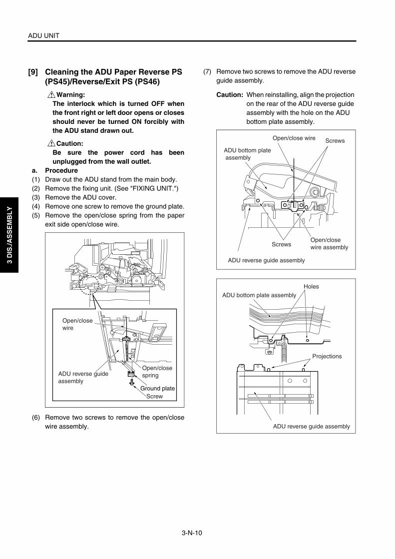
ADU UNIT
3-N-10
3 D
IS./A
SS
EM
BL
Y
[9] Cleaning the ADU Paper Reverse PS (PS45)/Reverse/Exit PS (PS46)
Warning:The interlock which is turned OFF whenthe front right or left door opens or closesshould never be turned ON forcibly withthe ADU stand drawn out.
Caution:Be sure the power cord has beenunplugged from the wall outlet.
a. Procedure(1) Draw out the ADU stand from the main body.(2) Remove the fixing unit. (See "FIXING UNIT.")(3) Remove the ADU cover.(4) Remove one screw to remove the ground plate.(5) Remove the open/close spring from the paper
exit side open/close wire.
(6) Remove two screws to remove the open/closewire assembly.
(7) Remove two screws to remove the ADU reverseguide assembly.
Caution: When reinstalling, align the projection on the rear of the ADU reverse guide assembly with the hole on the ADU bottom plate assembly.
Open/close wire
ADU reverse guide assembly
Screw
Open/close spring
Ground plate
ADU reverse guide assembly
Open/close wire
ADU bottom plate assembly
Screws
ScrewsOpen/close wire assembly
Holes
Projections
ADU reverse guide assembly
ADU bottom plate assembly

ADU UNIT
3-N-11
3 D
IS./A
SS
EM
BL
Y
(8) Remove the nine screws illustrated from the bot-tom of the ADU stand.
(9) Remove one screw while holding the ADU bot-tom plate assembly to remove the paper feedside open/close wire.
Caution: Be sure to hold ADU bottom plate assembly when removing the screws because the ADU bottom plate assembly becomes free when the paper feed side open/close wire is removed.
(10) Lower the ADU bottom plate assembly straightdown and remove the ADU guide cover.
(11) Clean the ADU paper reverse PS (PS45) andreverse/exit PS (PS46) with a blower brush.
(12) Reinstall the above parts following the removalsteps in reverse.
Front
Screws
ADU bottom plate assembly
Paper exit side
Screws
ADU bottom plate assembly
Screws
Open/close wire
ADU guide coverADU bottom plate assembly
Reverse/exit PS (PS46)
ADU paper reverse PS (PS45)

ADU UNIT
3-N-12
3 D
IS./A
SS
EM
BL
Y
[10] Removing and Reinstalling the ADU Reverse Roller
Warning:The interlock which is turned OFF whenthe front right or left door opens or closesshould never be turned ON forcibly withthe ADU stand drawn out.
Caution:Be sure the power cord has beenunplugged from the wall outlet.
a. Procedure(1) Draw out the ADU stand from the main body.(2) Remove the fixing unit. (See "FIXING UNIT.")(3) Remove the ADU cover.(4) Remove the ADU guide cover.(5) Remove the screw to remove two wiring har-
nesses.(6) Remove E-ring (1) to remove the paper eject
reverse gear (1) and pin.(7) Remove E-ring (2) to remove the rear side bear-
ing.(8) Remove E-ring (3) to remove the front side bear-
ing.
(9) Slide the ADU reverse roller to the upper sideand then to the lower side to slide it out.
(10) Reinstall the above parts following the removalsteps in reverse.
Paper exit reverse gear (1) E-ring (1)
Pin
Wiring harnesses
BearingE-ring (2)
Screws
Bearing
E-ring (3)
ADU reverse roller

ADU UNIT
3-N-13
3 D
IS./A
SS
EM
BL
Y
[11] Removing and Reinstalling the ADU Stand
Warning:The interlock which is turned OFF whenthe front right or left door opens or closesshould never be turned ON forcibly withthe ADU stand drawn out.
Warning:Removal and reinstallation of the ADUstand involve carrying a heavy load so itshould be performed by two persons.
Caution:Be sure the power cord has beenunplugged from the wall outlet.
a. Procedure(1) Draw out the ADU stand from the main body.(2) Remove the fixing unit. (See "FIXING UNIT.")(3) Remove the transfer/separation corona unit.
(See "CORONA UNIT.")(4) Remove the second paper feed unit.(5) Remove the front right door and the front left
door. (See "EXTERNAL SECTION.")
(6) Remove one screw (in the case of the Di551/Di650) or loosen one screw (in the case of theDi5510/Di7210) to detach the connector cover.
(7) Remove the screw to loosen the stay.
(8) Disconnect the three relay connectors (CN445,446, 447).
Caution: Disconnect each connector on the ADU stand.
Relay connector (CN445)
Stay
Screw
Relay connector (CN447)
Relay connector (CN446)
Screw
Connector cover

ADU UNIT
3-N-14
3 D
IS./A
SS
EM
BL
Y
(9) Remove one screw to release the lock of the han-dle(right).
(10) Remove the two screws securing the guide railson the paper feed side and paper exit side.
Caution: Do not mistake the screws securing the guide rails for screws(black) that must not be removed. (Black screws must not be removed)
(11) To remove the ADU stand, one person holds thehandle(right) on the paper-feed side, and theother holds the the handle(left) on the fixing unit.Then, they lift up the ADU stand.
(12) Reinstall the above parts following the removalsteps in reverse.
[12] Removing and Reinstalling the Pre-registration Roller
Warning:The interlock which is turned OFF whenthe front right or left door opens or closesshould never be turned ON forcibly withthe ADU stand drawn out.
Warning:Removal and reinstallation of the ADUstand involve carrying a heavy load so itshould be performed by two persons.
Caution:Be sure the power cord has beenunplugged from the wall outlet.
a. Procedure(1) Remove the front and rear registration springs.
Caution: When reinstalling, pay attention to the location of the registration spring hook.
(2) Remove the E-ring (φ6)(3) Press the cleaner coupling and pull out the pin. (4) Remove the spring.(5) Remove the front and rear E-rings (φ8) and
remove each bearing.Screws
Screws
Screw
Screws
Handle (left)
Handle (right)
ADU stand
Guide rail
Guide rail
Screws that must not be removed (Black)
Handle (right)
Both the left and right black screws must not be removeed.

ADU UNIT
3-N-15
3 D
IS./A
SS
EM
BL
Y
(6) Slide the ADU pre-registration roller back andforth to remove.
(7) Reinstall the above parts following the removalsteps in reverse.
[13] Removing and Reinstalling the ADU Conveyance Roller 3 and 4
Warning:The interlock which is turned OFF whenthe front right or left door opens or closesshould never be turned ON forcibly withthe ADU stand drawn out.
Warning:Removal and reinstallation of the ADUstand involve carrying a heavy load so itshould be performed by two persons.
Caution:Be sure the power cord has beenunplugged from the wall outlet.
a. Procedure(1) Draw out the ADU stand from the main body.(2) Remove the fixing unit. (See "FIXING UNIT.")(3) Remove the transfer/separation corona unit.
(See "CORONA UNIT SECTION.")(4) Remove the second paper feed unit.(5) Remove the ADU stand.(6) Remove two screws to detach the conveyance
duct (rear assembly).
E-ring( / 8)E-ring( / 6)
Hook
Bearing
Spring
Cleaner coupling
Pin
Registration spring
Pre-registration roller
Registration spring
Bearing
Hook
E-ring( / 8)
Polyslider
Conveyance duct (rear assembly)
Screws

ADU UNIT
3-N-16
3 D
IS./A
SS
EM
BL
Y
(7) Remove two screws to release the high voltagesupply unit (1).
(8) Disconnect the two connectors (CN460, 461).
Caution: Each relay connector consists of two male sides and one female side. Be sure to remove only the male side (shown below) of the connector.
(9) Remove two screws to remove the conveyanceunit.
(10) Disconnect the three connectors (CN421, 426,427)
Caution: Each relay connector consists of two male sides and one female side. Be sure to remove only the male side (shown below) of the connector.
(11) Remove two screws to remove the harnessguide plate (front).
(12) Remove four screws to detach the registrationdrive motor assembly.
High voltage supply unit (1)
ScrewsRelay connector (CN460)
Relay connector (CN461)
Conveyance unit
Screw
Relay connector (CN427)
Harness guide plate (front)
Screw
Screw
Relay connector (CN426)
Relay connector (CN421)
Registration drive motor assemblyScrew
Screws(3)

ADU UNIT
3-N-17
3 D
IS./A
SS
EM
BL
Y
(13) Remove the stop rings to remove the ADU decel-eration MC (MC2) and ADU conveyance MC(MC13).
(14) Remove the E-ring at the rear, two belt holdingcollars, ADU conveyance belt (1), and two ADUconveyance pulleys.
(15) Remove the pin from each roller shaft.(16) Remove the E-ring and bearing on the inside of
the ADU conveyance pulley.(17) Remove the E-ring on the ADU conveyance
roller(3) shaft.
(18) Remove the front E-ring and bearing, andremove the ADU conveyance roller (3) and ADUconveyance roller (4) by sliding them back andforth.
(19) Reinstall the above parts following the removalsteps in reverse.
ADU conveyance MC (MC13)
ADU deceleration MC (MC2)
Stop rings
ADU conveyance belt (1)
Bearing E-ring Pin
Belt holding collars
E-rings
Pin
Bearing
ADU conveyance pulley
ADU conveyance roller (3)
ADU conveyance roller (4)
Bearing
E-ringsE-ring
E-ring

ADU UNIT
3-N-18
3 D
IS./A
SS
EM
BL
Y
[14] Removing and Reinstalling the ADU Conveyanece Roller 1 and 2
Warning:The interlock which is turned OFF whenthe front right or left door opens or closesshould never be turned ON forcibly withthe ADU stand drawn out.
Warning:Removal and reinstallation of the ADUstand involve carrying a heavy load so itshould be performed by two persons.
Caution:Be sure the power cord has beenunplugged from the wall outlet.
a. Procedure(1) Draw out the ADU stand from the main body.(2) Remove the fixing unit. (See "FIXING UNIT.")(3) Remove the transfer/separation corona unit.
(See "CORONA UNIT.")(4) Remove the second paper feed unit.(5) Remove the ADU stand.(6) Remove the conveyance unit.(7) Remove the ADU conveyance MC(MC13).(8) Disconnect the connector (CN407).(9) Remove three screws to detach the reverse gate
solenoid assembly.(10) Remove one screw to remove the connector
cover.
(11) Disconnect the connector (CN415).(12) Remove three screws to detach the reverse
motor assembly.
Connector cover
Screws
Reverse motor assembly
Connector (CN415)
Screw
Screws
Connector (CN407)
Reverse gate solenoid assembly

ADU UNIT
3-N-19
3 D
IS./A
SS
EM
BL
Y
(13) Disconnect the two connectors (CN403, 404).(14) Disconnect the connector (CN417).
Caution: Each relay connector consists of two male sides and one female side. Be sure to remove only the male side (shown below) of the connector.
(15) Remove one screw to remove the wiring harnessfor CN404.
(16) Remove eight screws (three front, five rear) andturn over the fixing attachment rail assembly tothe paper exit side.
(17) Remove the E-ring from ADU conveyance roller(2) shaft.
(18) Remove the front E-ring, two belt holding collars,ADU conveyance belt (2), and two ADU convey-ance pulleys.
(19) Remove the pin from the shaft of each roller.(20) Remove the E-ring and bearing inside the ADU
conveyance pulley.(21) Remove the rear E-ring and bearing, and remove
the ADU conveyance roller (1) and ADU convey-ance roller (2) by sliding them back and forth.
(22) Reinstall the above parts following the removalsteps in reverse.
Screws
Relay connector (CN417)
Fixing attachment rail assembly
Relay connector (CN404)
ScrewsRelay connector (CN403)
Wiring harnesses Screw
E-ring, bearing Belt holding collars, ADU transport pulleys
Pin
E-rings
Pin
ADU conveyance roller (2) shaftADU conveyance
belt (2)
ADU conveyance roller (2)
ADU conveyance roller (1)
Bearing
E-rings

ADU UNIT
3-N-20
3 D
IS./A
SS
EM
BL
Y
[15] Removing and Reinstalling the Paper Reverse/Exit Roller
Warning:The interlock which is turned OFF whenthe front right or left door opens or closesshould never be turned ON forcibly withthe ADU stand drawn out.
Warning:Removal and reinstallation of the ADUstand involve carrying a heavy load so itshould be performed by two persons.
Caution:Be sure the power cord has beenunplugged from the wall outlet.
a. Procedure(1) Draw out the ADU stand from the main body.(2) Remove the fixing unit. (See "FIXING UNIT.")(3) Remove the transfer/separation corona unit.
(See "CORONA UNIT.")(4) Remove the second paper feed unit.(5) Remove the ADU stand.(6) Remove the conveyance unit.(7) Remove the ADU conveyance roller (1).(8) Remove the screw to remove the paper reverse/
exit roller rotation knob.(9) Remove the front E-ring and remove the bearing.(10) Remove the rear E-ring to remove the paper exit
reverse gear (1) and pin.(11) Remove the E-ring and remove the bearing.
(12) Remove the paper reverse/exit roller by sliding itback and forth.
(13) Reinstall the above parts following the removalsteps in reverse.
E-ring
E-ring
E-ring
Bearing
Bearing
Pin
Screw
Paper reverse/exit roller
Paper exit/reverse gear (1)
Paper reverse/exit roller rotation knob
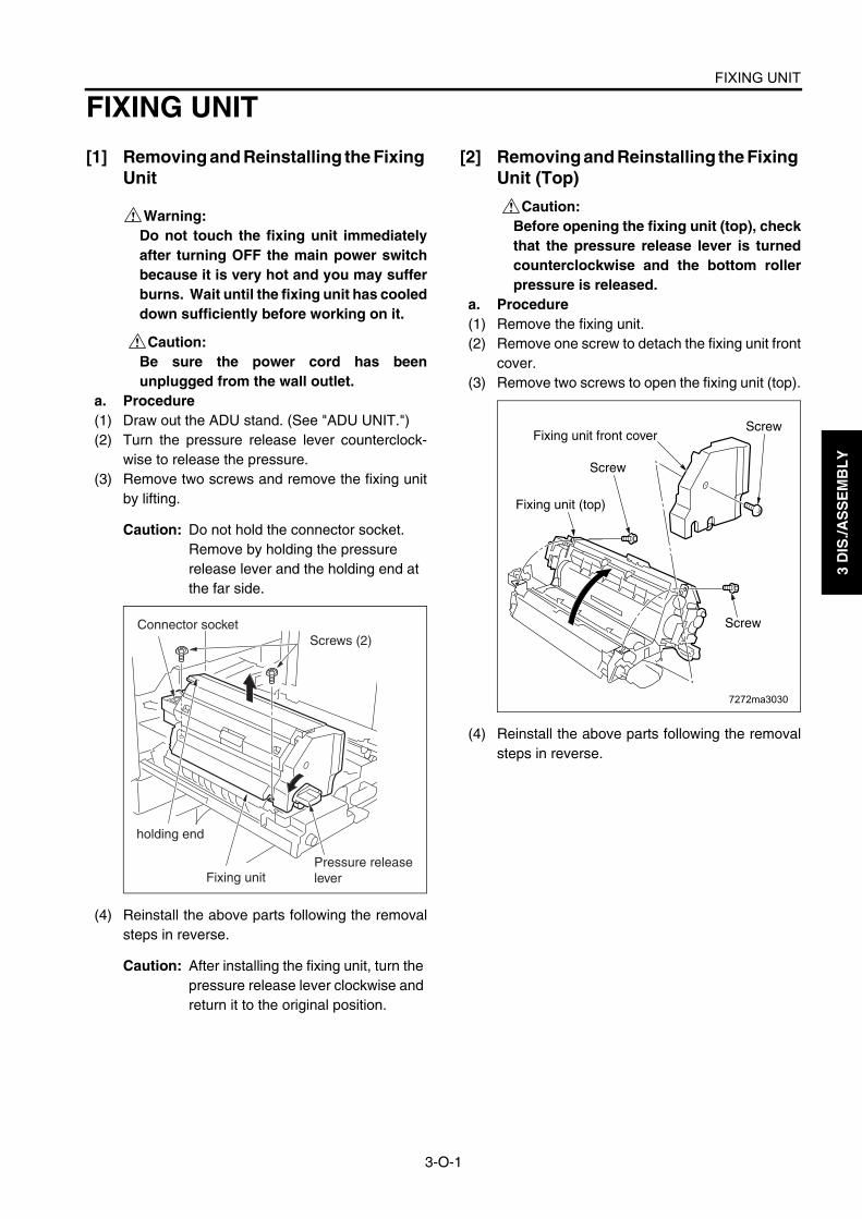
FIXING UNIT
3-O-1
3 D
IS./A
SS
EM
BL
Y
FIXING UNIT
[1] Removing and Reinstalling the Fixing Unit
Warning:Do not touch the fixing unit immediatelyafter turning OFF the main power switchbecause it is very hot and you may sufferburns. Wait until the fixing unit has cooleddown sufficiently before working on it.
Caution:Be sure the power cord has beenunplugged from the wall outlet.
a. Procedure(1) Draw out the ADU stand. (See "ADU UNIT.")(2) Turn the pressure release lever counterclock-
wise to release the pressure.(3) Remove two screws and remove the fixing unit
by lifting.
Caution: Do not hold the connector socket. Remove by holding the pressure release lever and the holding end at the far side.
(4) Reinstall the above parts following the removalsteps in reverse.
Caution: After installing the fixing unit, turn the pressure release lever clockwise and return it to the original position.
[2] Removing and Reinstalling the Fixing Unit (Top)
Caution:Before opening the fixing unit (top), checkthat the pressure release lever is turnedcounterclockwise and the bottom rollerpressure is released.
a. Procedure(1) Remove the fixing unit.(2) Remove one screw to detach the fixing unit front
cover.(3) Remove two screws to open the fixing unit (top).
(4) Reinstall the above parts following the removalsteps in reverse.
Connector socketScrews (2)
Fixing unit
holding end
Pressure release lever
7272ma3030
Screw
Screw
Screw
Fixing unit front cover
Fixing unit (top)

FIXING UNIT
3-O-2
3 D
IS./A
SS
EM
BL
Y
[3] Removing and Reinstalling the Web Cover
a. Procedure(1) Remove the fixing unit.(2) Remove the fixing unit front cover.(3) Open the fixing separation claw (upper) unit and
remove two screws inside.(4) Remove two screws to detach the web cover.
(5) Reinstall the above parts following the removalsteps in reverse.
[4] Removing and Reinstalling the Clean-ing Web
a. Procedure(1) Draw out the ADU stand. (See "ADU UNIT.")(2) Remove the web cover.(3) Remove two screws to remove the cleaning web
unit.
(4) Reinstall the above parts following the removalsteps in reverse.Caution1: When reinstalling, make sure the
cleaning web does not sag.Caution2: When reinstalling, wind it until the
red line of the cleaning web is fullywound to the take-up shaft.
Caution3: After replacing the cleaning web,make sure to reset the count value ofthe fixing unit cleaning web by "CopyCount by Parts to be Replaced(Fixed Parts)" in the 25 mode.
Fixing separation claw (upper) unit Web cover
Screws (2)
Screw
Screws (2) Fixing unit front cover
Cleaning web unitScrews (2)

FIXING UNIT
3-O-3
3 D
IS./A
SS
EM
BL
Y
[5] Replacing the Fixing Heater Lamps (L2, L3)
Caution:Do not touch the fixing heater lamp withbare hands.
Caution1: Install the heater lamp with the man-ufacturers mark facing the rear.
Caution2: The heater lamp should not touchthe inner surface of the upper roller.
Caution3: When replacing the heater lamp, besure to insert the lamp end in thelamp terminal securely. Also, checkthat the Faston terminals are con-nected correctly.
a. Procedure(1) Remove the fixing unit.(2) Remove the fixing unit front cover.(3) Remove the screw at the front to remove the
lamp fixing plate (front).(4) Remove the front lamp harness from the harness
guide to remove the two Faston terminals.
Caution: When removing the Faston terminals, be sure to hold the connector. Con-nector cannot be removed by pulling on the harness.
(5) Open the fixing unit (top).(6) Remove the screw at the far side to remove the
lamp fixing plate (rear).
(7) Remove the two Faston terminals of the far sidelamp.
Caution: When removing the Faston terminals, be sure to hold the connector. Con-nector cannot be removed by pulling on the harness.
(8) Pull out the fixing heater lamps (L2, L3) from thefront side of the fixing upper roller.
Faston terminals (2)
Screw
Harness guide
Lamp fixing plate (front)
Faston terminals (2)
Screw
Lamp fixing plate (rear)
Fixing heater lamps (L2, L3)

FIXING UNIT
3-O-4
3 D
IS./A
SS
EM
BL
Y
(9) Reinstall the above parts following the removalsteps in reverse.
Caution: When installing the lamps, pay atten-tion to their orientation. The size of the lamp terminal mounting hole in the front lamp fixing plate is different from that in the rear lamp fixing plate. The lamp cannot be installed properly if it is facing the opposite direction.
[6] Replacing the Fixing Heater Lamp(L4)
Caution:Do not touch the fixing heater lamp withbare hands.
Caution1: Install the heater lamp with the man-ufacturers mark facing the rear.
Caution2: The heater lamp should not touchthe inner surface of the upper roller.
Caution3: When replacing the heater lamp, besure to insert the lamp end in thelamp terminal securely. Also, checkthat the Faston terminals are con-nected properly.
a. Procedure(1) Open the fixing cover (upper).(2) Remove the screw at front to remove the lamp
fixing plate (lower front).(3) Remove the Faston terminal.
Fastonterminal
ScrewLamp fixing plate (lower front)

FIXING UNIT
3-O-5
3 D
IS./A
SS
EM
BL
Y
(4) Remove the rear lamp harness from the two har-ness guide to remove the Faston terminal.
(5) Pull out the fixing heater lamp (L4) from the frontside of the fixing lower roller.
(6) Reinstall the above parts following the removalsteps in reverse.
Caution: When installing the lamp, pay atten-tion to its orientation. The lamp cannot be installed properly if it is facing the opposite direction.
[7] Removing and Reinstalling the Fixing Separation Claw (Upper) Unit and Fix-ing Separation Claws (Upper)
a. Procedure(1) Remove the fixing unit.(2) Remove the fixing unit front cover.(3) Remove the web cover.(4) Remove the screw to detach the fixture.(5) Remove the fixing separation claw (upper) unit
(6) Remove the screw to remove the upper separa-tion claw support shaft from the fixing separationclaw (upper) unit.
Caution: Be careful when removing the shaft because it bends easily.
(7) Remove six springs attached to the fixing sepa-ration claw (upper) unit.
(8) Remove six fixing separation claws (upper).
Harness guides
Faston terminalLamp fixing plate (rear)
Fixing heater lamp (L4)
Fixing separation claw (upper) unit
Fixture
Screw
Screw
Separation claw (upper) support shaft
Spring
Fixing separation claw (upper) (6)

FIXING UNIT
3-O-6
3 D
IS./A
SS
EM
BL
Y
(9) Reinstall the above parts following the removalsteps in reverse.
Caution: After installing the fixing separation claw (upper), move the upper claws with your finger and check that they return with the force of the spring.
[8] Removing and Reinstalling the Fixing Separation Claw (Lower) Unit and Fix-ing Separation Claws (Lower)
a. Procedure(1) Remove the fixing unit.(2) Open the fixing unit (upper).(3) Remove two screws to detach the fixing separa-
tion claw (lower) assembly.(4) Remove the three springs from the three fixing
separation claws (lower).(5) Slide the frame holding the fixing separation
claws (lower) and remove the three claws.
(6) Reinstall the above parts following the removalsteps in reverse.
Caution: After installing the fixing separation claw (lower), check that the frame moves smoothly.
Fixing separation claws (lower) (3)
Spring
Screws(2)
Frame
Fixing separation claw (lower) assembly

FIXING UNIT
3-O-7
3 D
IS./A
SS
EM
BL
Y
[9] Removing and Reinstalling the Fixing Upper Roller and Fixing Drive Gear
a. Procedure(1) Remove the fixing unit.(2) Remove the fixing unit front cover.(3) Remove the fixing separation claw (upper) unit.(4) Open the fixing unit (top).(5) Remove the fixing heater lamps (L2, L3).(6) Remove the two C-rings, fixing drive gear, gear,
two bearings, two washers (Di5510/Di7210: onewasher) and two insulating sleeves from the fix-ing upper roller.
(7) Remove the fixing upper roller from the frame.
(8) Reinstall the above parts following the removalsteps in reverse.Caution1: Before reinstalling the insulating
sleeve, coat the inside with Tri-flow.Caution2: Reinstall the bearings and insulating
sleeves with the collars facing thedirections shown in the figure.
Caution3: When reinstalling the fixing upperroller, the Lot No. or the grooveslocated on the circumference of theroller edge should be directed towardthe front side.And, refer to the following list forchecking the type of the fixing upperrollers.
Caution4: The fixing drive gear of Di551/Di650is different from that of Di5510/Di7210.The fixing drive gear of Di5510/Di7210 is designated for periodicalreplacement parts.
7272ma3035
C-ringGear
Washer
BearingInsulating sleeve
Fixing upper roller
Fixing unit (upper)
C-ring
Fixing drive gear
Washer(Di551/Di650 only)
Bearing
Insulating sleeve
CollarsCollars
Number of grooves on the circumference of the roller edge
Di551/Di5510 2Di650/Di7210 None (only Lot No.)

FIXING UNIT
3-O-8
3 D
IS./A
SS
EM
BL
Y
[10] Removing and Reinstalling the Fixing Lower Roller
a. Procedure(1) Remove the fixing unit.(2) Remove two screws to remove the fixing
entrance guide plate (lower)
(3) Remove the fixing separation claw (lower) unit.(4) Remove the fixing lower roller upward.(5) Remove two bearings from the fixing lower roller.
(6) Reinstall the above parts following the removalsteps in reverse.
Caution: The fixing entrance guide plate (lower) should be pressed against the fixing upper roller bearing when installing.
[11] Removing and Reinstalling the De-curler roller
a. Procedure(1) Remove the fixing unit.(2) Open the fixing unit (top).(3) Lift the fixing exit guide plate (upper) and remove
two screws to remove the fixing exit guide plate(lower).
(4) Remove the screw to detach the jam handlingrelease knob.
(5) From the front side, remove one E-ring, one gear,one E-ring, two washers, one screw, and bearingin this order.
(6) From the rear side, remove one E-ring, two wash-ers, one screw, and bearing in this order and thenremove the decurler roller from the frame.
Fixing entrance guide plate (lower)
Screw
Screw
Fixing lower roller
Bearing
Bearing
7272ma3036
Fixing exit guide plate (lower)
Fixing exit guide plate (lower)
Screw
Screw
Screw
Screw
Screw
E-ring
E-ring
Fixing exit guide plate (lower)
Fixing exit guide plate (upper)
E-ring
Bearing
Washer
Washer
Gear
Jam handling release knob
Washer
Washer
Bearing
Decurler roller
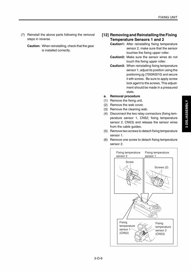
FIXING UNIT
3-O-9
3 D
IS./A
SS
EM
BL
Y
(7) Reinstall the above parts following the removalsteps in reverse.
Caution: When reinstalling, check that the gear is installed correctly.
[12] Removing and Reinstalling the Fixing Temperature Sensors 1 and 2Caution1: After reinstalling fixing temperature
sensor 2, make sure that the sensortouches the fixing upper roller.
Caution2: Make sure the sensor wires do nottouch the fixing upper roller.
Caution3: When reinstalling fixing temperaturesensor 1, adjust its position using thepositioning jig (7050K0010) and secureit with screws. Be sure to apply screwlock agent to the screws. This adjust-ment should be made in a pressuredstate.
a. Removal procedure(1) Remove the fixing unit.(2) Remove the web cover.(3) Remove the cleaning web.(4) Disconnect the two relay connectors (fixing tem-
perature sensor 1, CN52; fixing temperaturesensor 2, CN53) and release the sensor wiresfrom the cable guides.
(5) Remove two screws to detach fixing temperaturesensor 1.
(6) Remove one screw to detach fixing temperaturesensor 2.
Fixing temperature sensor 2
Fixing temperature sensor 1
Screw
Screws (2)
Fixing temperature sensor 1(CN52)
Fixing temperature sensor 2(CN53)

FIXING UNIT
3-O-10
3 D
IS./A
SS
EM
BL
Y
b. Reinstallation procedure(1) Secure fixing temperature sensor 2 to the fixing
plate with a screw.
Caution: Be careful not to apply a pressure to the sensor welding portion [A].
(2) Make sure that fixing temperature sensor 2touches the fixing upper roller. If they do nottouch each other, be sure to bring the sensor incontact with the roller.
(3) Set a fixing temperature sensor positioning jigbetween fixing temperature sensor 1 and fixingupper roller, and secure fixing temperature sen-sor 1 with two screws so that the distancebetween the sensor and roller is equal to thethickness of the jig.
a) Set the distance "a" between the fixing tem-perature sensor 1 and fixing upper roller sothat it is equal to the thickness of the position-ing jig.
(4) Apply screw lock agent to the two screws secur-ing fixing temperature sensor 1.
(5) Secure the wires of fixing temperature sensors 1and 2 in the wire guides and connect their con-nectors.
(6) Reverse the removal procedure to reinstall otherparts.
7272ma3037
[A]
Fixing temperature sensor 2
Screw
The fixing temperature sensor 2 must contact the fixing upper roller.
Fixing upper roller Screws(2)
Fixing temperature sensor 1
Positioning jig(7050K0010)
a
Fixing temperature sensor 1
Fixing upper roller
Standard value of a: 0.75 0.05mm

FIXING UNIT
3-O-11
3 D
IS./A
SS
EM
BL
Y
[13] Removing and Reinstalling the Ther-mostat/U (TS1)
Caution:This is an important safety part. (P/N:SP00-0020) Be sure to observe the follow-ing cautions and steps when removing orreinstalling.
Caution1: After reinstalling the thermostat/U,make sure that its wires do not touchthe fixing upper roller.
Caution2: When reinstalling the thermostat/U,adjust its position using the position-ing jig (00M8-1-00) and secure it withscrews. Be sure to apply screw lockagent to the screws. This adjustmentshould be made in a pressured state.
a. Removal procedure(1) Remove the fixing unit.(2) Remove the web cover.(3) Remove the cleaning web.(4) Remove one screw and two Faston terminals to
detach the thermostat/U.
b. Reinstallation procedure(1) Connect two Faston terminals to the thermostat/
U.(2) Set a thermostat positioning jig (00M8-1-00)
between the thermostat/U and fixing upper rollerand secure the thermostat/U with one screw sothat the distance between the roller and thermo-stat/U is equal to the thickness of the jig.
a) Set the distance "a" between the thermostat/U and fixing upper roller so that it is equal tothe thickness (B) of the positioning jig.
Screw
Thermostat/U (TS1)
Faston terminals (2)
Faston terminal
Faston terminal
Screw
Thermostat/U (TS1)
Positioning jig
Fixing upper roller
(00M8-1-00)
Thermostat/U(TS1)
a
Fixing upper roller
Standard value of a: 3.75 0.25mm

FIXING UNIT
3-O-12
3 D
IS./A
SS
EM
BL
Y
b) When making the adjustment, make sure thatthe thermostat/U does not ride on the posi-tioning jig (C).
(3) Apply screw lock agent to the screw securing thethermostat/U.
(4) Reverse the removal procedure to install otherparts.
[14] Removing and Reinstalling the Ther-mostat/L (TS2)
Caution:This is an important safety part. (P/N :SP00-0010) Be sure to observe the follow-ing cautions and steps when removing orreinstalling.
Caution1: After reinstalling the thermostat/L,make sure that its wires do not touchthe fixing lower roller.
Caution2: When reinstalling the thermostat/L,adjust its position using the position-ing jig (56AEJG011) and secure itwith screws. Be sure to apply screwlock agent to the screws. This adjust-ment should be made in a pressuredstate.
a. Removal procedure(1) Remove the fixing lower roller.(2) Close the fixing cover (top).(3) Remove the two Faston terminals of the thermo-
stat/L through the fixing entrance side.
(4) Open the fixing cover (top).(5) Remove two screws to remove the thermostat/L.
(A)
(B)
(C)
Faston
Screws
Thermostat/L
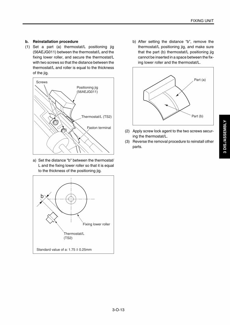
FIXING UNIT
3-O-13
3 D
IS./A
SS
EM
BL
Y
b. Reinstallation procedure(1) Set a part (a) thermostat/L positioning jig
(56AEJG011) between the thermostat/L and thefixing lower roller, and secure the thermostat/Lwith two screws so that the distance between thethermostat/L and roller is equal to the thicknessof the jig.
a) Set the distance "b" between the thermostat/L and the fixing lower roller so that it is equalto the thickness of the positioning jig.
b) After setting the distance “b”, remove thethermostat/L positioning jig, and make surethat the part (b) thermostat/L positioning jigcannot be inserted in a space between the fix-ing lower roller and the thermostat/L.
(2) Apply screw lock agent to the two screws secur-ing the thermostat/L.
(3) Reverse the removal procedure to reinstall otherparts.
Screws
Faston terminal
Thermostat/L (TS2)
Positioning jig(56AEJG011)
Thermostat/L(TS2)
b
Fixing lower roller
Standard value of a: 1.75 0.25mm
Part (a)
Part (b)

3 D
IS./A
SS
EM
BL
Y
Blank page


![Konika 454e-20180814115451 - primariacrasna.roprimariacrasna.ro/2018/Consiliul Local]/Inv_ITP.pdf · combatere a finantärii terorismului, republicatä, cu modificärile ulterioare,](https://static.fdocuments.us/doc/165x107/5e0ee6b81524e744d1695a92/konika-454e-20180814115451-localinvitppdf-combatere-a-finantrii-terorismului.jpg)