Knife gate valve HP - Stafsjö · Stafsjö’s knife gate valve HP has excellent flow...
11
Data is only for informational purpose. All specifications are subject to change without notice. Knife gate valve HP
Transcript of Knife gate valve HP - Stafsjö · Stafsjö’s knife gate valve HP has excellent flow...

1 2015-06-18 issue 10Data is only for informational purpose. All specifications are subject to change without notice.
Knife gate valve HP

2 2015-06-18 issue 10
Reliable shut-off and bi-direc-tional sealingThe retainer ring system on both sides of the gate makes it independent of flow di-rection. The through-going gate assures a reliable shut-off of highly concentrated and static media.
A bore with excellent flow charac-teristics In open position, the HP valve’s bore has almost no cavity at all, making the flow characteristics really excellent. In this position the PTFE seats are protected by the retainer rings and the gate.
Solid design to preserve a first rate sealingThe gate is supported all the way from opened to closed position which, together with a proper dimensioned top works, makes the shut-off reliable and repeat-able.
Knife gate valve HPStafsjö’s knife gate valve HP has excellent flow characteristics and gives a bi-directional tight high pressure sealing. The valve is equipped with a through-going gate for secure shut-off of con-centrated and static media. This shut-off performance, along with its flow characteristics, makes it suitable for severe operating con-ditions with media such as pulp (pulp concentration > 5%), liquor, reject, slurry, powder and ash.
HP is supplied as standard with a valve body in stainless steel, which has integrated purge ports and guiding strips. To enable bi-directional pressures, the HP has the retainer ring system on both body halves. The gate is as standard supplied in duplex stainless steel and an optional hard chromed surface further increase the wear resistance. The gland boxes are equipped with Stafsjö’s box packing TwinPack™, to secure that no media reaches the surrounding envi-ronment. The gland boxes can also be supplied with a box bottom scraper or with double gland for the most demanding applications.
The top work consists of aluminium beams and stainless steel tie rods, which gives good corrosion resistance and a stable operation. The valve is modular designed and can easily be customized to spe-cific processes requirements. There are several actuator types and accessories to choose from in our standard collection.
The HP valve is designed, manufactured, inspected and tested according to the European Pressure Equipment Directive (PED 97/ 23/EC) category I and II module A1. The valve is CE marked when it is applicable.
The HP valve is one out of five valves in Stafsjö’s procuct range with through-going gates. HG represent the standard and HL is a slim line version of HG. HPT is a high pressure version entirely made in Titanium. Finally the HX is an extreme high pressure version.

3 2015-06-18 issue 10
Design data
Sizes Flange drilling Face-to-face dimension ATEX design Corrosion protection
DN 300 - DN 900 EN 1092 PN 10EN 1092 PN 16JIS B 2238 10KASME/ANSI B16.5 Class 150, ASME/ANSI B16.47 Class 150, series A
Stafsjö manufacturing standardMSS SP-81TAPPI TIS 405-8
ATEX 94/ 9/EC II cat 3 G/D for zone 2 and 22 on request
Non-corrosive resistant materials are coated in colour RAL5015 acc. to Stafsjö’s standard, which fulfill the requirements in EN ISO 12944 class C3.
Other sizes, flange drillings, ATEX zones and corrosion protection on request.
Leakage rate Pressure tests
EN 12266-1:2012 Rate A: no visually detectable leakage is allowed for duration of the test
Pressure tests are performed with water at 20º C according to EN 12266-1:2012.Pressure for shell test: 1,5 times maximum allowable working pressure for open valve. Pressure for seat tightness test: 1,1 times maximum allowable differential pressure for closed valve.
Maximum working pressure body at 20°C Maximum differential pressure at 20°C
DN bar DN bar
300 - 800 10 300 - 800 10
900 6 900 6
Basic equipment
A. Valve Body
Material Code Type Maximum temperature °C
Stainless steel (E) EN 1.4408 400
The valve body is as standard supplied with purge ports G1/2”
B. Gate
Material Type Option
Duplex stainless steel EN 1.4462/S32205 Hard chromed surface
C. Retainer rings
Material Type
Stainless steel EN 1.4408
D. Seats
Material Code Maximum temperature °C
PTFE with o-ring Nitrile (P) 100
PTFE with o-ring Viton (PV) 180
E. Box Packing
Material Code Maximum temperature °C
TwinPackTM (TY) 260
WhitePackTM (WP) 260
Actuators
Manual Code Automatic Code
Hand wheel1) (HW) Pneumatic cylinder (EC)
Chain wheel2) (CW) Electrical motor (EM)
Hydraulic cylinder2) (MH)1) For recommended size, see page 5 column E2) For recommended size, see separate data sheet
4 2015-06-18 issue 10
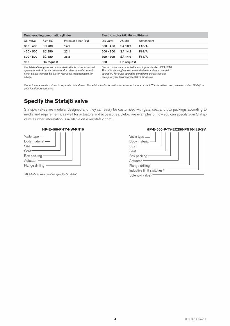
Specify the Stafsjö valveStafsjö’s valves are modular designed and they can easily be customized with gate, seat and box packings according to media and requirements, as well for actuators and accessories. Below are examples of how you can specify your Stafsjö valve. Further information is available on www.stafsjo.com.
Vavle typeBody materialSizeSeatBox packingActuatorFlange drilling
HP-E-400-P-TY-HW-PN10
Vavle typeBody materialSizeSeatBox packing ActuatorFlange drillingInductive limit switches3)
Solenoid valve3)
HP-E-500-P-TY-EC250-PN10-ILS-SV
3) All electronics must be specified in detail.
Double-acting pneumatic cylinder Electric motor (AUMA multi-turn)
DN valve Size EC Force at 5 bar (kN) DN valve AUMA Attachment
300 - 400 EC 200 14,1 300 - 450 SA 10.2 F10/A
450 - 500 EC 250 22,1 500 - 600 SA 14.2 F14/A
600 - 800 EC 320 36,2 700 - 800 SA 14.6 F14/A
900 On request 900 On request
The table above gives recommended cylinder sizes at normal operation with 5 bar air pressure. For other operating condi-tions, please contact Stafsjö or your local representative for advice.
Electric motors are mounted according to standard ISO 5210. The table above gives recommended motor sizes at normal operation. For other operating conditions, please contact Stafsjö or your local representative for advice.
The actuators are described in separate data sheets. For advice and information on other actuators or on ATEX-classified ones, please contact Stafsjö or your local representative.

5
13
9
8
10
12
7
8
5
10
14a
9
11
6
15
3
1
2b18
16
16a
14b
8a
8c
8b
5a
5b
2c
2a
2
2b
8a
8c
8b
12a
4b
4a
4
2015-06-18 issue 10
Part list
Pos Detail Material (Type)
1 Hand wheel Coated cast iron (EN-JL1030/GG20)
2 Yoke Stainless steel (EN 1.4301)
3 Stem Stainless steel (EN 1.4104)
4 Stem nut Brass (CW603N alt. CW614N)
4a Washer Stainless steel (A2)
4b Screw Stainless steel (A2)
4c Washer Stainless steel (A2)
4d Nut Stainless steel (A2)
5 Tie rod Stainless steel (EN 1.4301)
5a Washer Stainless steel (A2)
5b Nut Stainless steel (A2)
6 Gate See equipment B
7 Beam Aluminium (EN AW-6063-T6)
8 Gland Stainless steel (EN 1.4408)
8a Stud bolt Stainless steel (A2), zinc coated
Pos Detail Material (Type)
8b Washer Stainless steel (A2)
8c Nut Stainless steel (A2), zinc coated
94) Box packing See equipment E
10 Valve body See equipment A
11 Body gasket PTFE
12 Retainer ring See equipment C
12a Locking screw Stainless steel (A2)
134) Seat See equipment D
14a Guide strip PTFE
14b Guide strip PTFE
15 Bushing Oil-bronze
16/a Gate guard,not for HW
Stainless steel (EN 1.4301)
18 Pneumatic cylinder See data sheet4) Recommended spare parts

6
DN A B C D E F G H J K L
300 302 78 375 180 400 865 893 1257 455 1420 720 170
350 332 78 425 175 400 980 948 1342 510 1505 775 200
400 380 89 480 210 520 1070 1033 1510 570 1650 873 290
450 420 89 534 220 520 1210 1124 1657 625 1790 963 425
500 470 114 580 320 635 1412 1299 1882 690 2020 1138 670
600 540 122 679 350 635 1553 1336 1981 800 2135 1175 820
700 665 128 800 320 635 1891 1556 2326 995 2505 1395 1300
800 760 128 900 320 635 2132 1721 2591 1070 2770 1560 1700
900 880 128 1010 310 - 2450 - 2886 1168 2940 1740 19602)
G
E
D
B
F
J
H
AC
K
STAFSJÖ STAFSJÖ STAFSJÖ
L
2015-06-18 issue 10
Main dimensions
Dimensions (mm)
Weight1)
1) Weight in kg for valve equipped with hand wheel.2) Weight in kg for valve equipped with double-acting pneumatic cylinderMain dimensions are only for information. Contact Stafsjö for certified drawings.

7
ß°
2ß°
ß°
2ß°
DN 350 - DN 400
DN 450 - DN 600
ß°
2ß°
ß°
2ß°
DN 700 - DN 800
DN 900
ß°
2ß°
DN 300DN 350 - DN 400
DN 450 - DN 600
DN 700 - DN 800
DN 900
DN 300
2015-06-18 issue 10
Flange drilling according to EN 1092 PN10
Flange drilling information (mm)
DN 300 350 400 450 500 600 700 800 900
Outside flange diameter 445 505 565 615 670 780 895 1015 1115
Bolt circle diameter 400 460 515 565 620 725 840 950 1050
Number of throughgoing bolts (○) 4 4 4 4 4 4 4 4 4
Number of tapped hole/side (●) 8 12 12 16 16 16 20 20 24
Bolt size M20 M20 M24 M24 M24 M27 M27 M30 M30
Size of throughgoing holes in flange Ø22 Ø22 Ø26 Ø26 Ø26 Ø30 Ø30 Ø33 Ø33
β° 15 11,25 11,25 9 9 9 7,5 7,5 6,43
Screw lengths1) 20 20 25 25 27 28 28 31 311) Add the values with the thickness of flanges, washers and gaskets.○ Throughgoing holes● Tapped holes
8
ß°
2ß°
ß°
2ß°
DN 350 - DN 400
DN 450 - DN 600
ß°
2ß°
ß°
2ß°
DN 700 - DN 800
DN 900
ß°
2ß°
DN 300DN 350 - DN 400
DN 450 - DN 600
DN 700 - DN 800
DN 900
DN 300
2015-06-18 issue 10
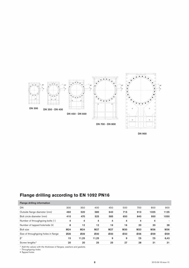
Flange drilling according to EN 1092 PN16
Flange drilling information
DN 300 350 400 450 500 700 800 900
Outside flange diameter (mm) 460 520 580 640 715 910 1025 1125
Bolt circle diameter (mm) 410 470 525 585 650 840 950 1050
Number of throughgoing bolts (○) 4 4 4 4 4 4 4 -
Number of tapped hole/side (●) 8 12 12 16 16 20 20 28
Bolt size M24 M24 M27 M27 M30 M33 M36 M36
Size of throughgoing holes in flange Ø26 Ø26 Ø30 Ø30 Ø33 Ø36 Ø39 Ø39
β° 15 11,25 11,25 9 9 7,5 7,5 6,43
Screw lengths1) 20 20 25 25 27 28 31 311) Add the values with the thickness of flanges, washers and gaskets.○ Throughgoing holes● Tapped holes

9
ß°
2ß°
DN 300 - DN 400
DN 450 - DN 500
ß°
2ß°
ß°
2ß°
DN 600 - DN 700
DN 800 - DN 900
ß°
2ß°
DN 450 - DN 500
DN 600 - DN 700
DN 800 - DN 900
DN 300 - DN 400
2015-06-18 issue 10
Flange drilling according to JIS B 2238 10K
Flange drilling information
DN 300 350 400 450 500 600 700 800 900
Outside flange diameter (mm) 445 490 550 620 675 795 905 1020 1120
Bolt circle diameter (mm) 400 445 510 565 620 730 840 950 1050
Number of throughgoing bolts (○) 4 4 4 4 4 4 4 4 4
Number of tapped hole/side (●) 12 12 12 16 16 20 20 24 24
Bolt size M22 M22 M24 M24 M24 M30 M30 M30 M30
Size of throughgoing holes in flange Ø26 Ø26 Ø26 Ø26 Ø27 Ø33 Ø33 Ø33 Ø33
β° 15 11,25 11,25 9 9 7,5 7,5 6,43 6,43
Screw lengths1) 20 20 25 25 27 28 28 31 311) Add the values with the thickness of flanges, washers and gaskets.○ Throughgoing holes● Tapped holes

10
ß°
2ß°
ß°
2ß°
DN 400 - DN 450
ß°
2ß°
DN 700 - DN 800
DN 900
ß°
2ß°
DN 300 - DN 350
ß°
2ß°
DN 500 - DN 600
ß°
2ß°
ß°
2ß°
DN 400 - DN 450
ß°
2ß°
DN 700 - DN 800
DN 900
ß°
2ß°
DN 300 - DN 350
ß°
2ß°
DN 500 - DN 600
DN 400 - DN 450
DN 500 - DN 600
DN 700 - DN 800
DN 900
DN 300 - DN 350
2015-06-18 issue 10
Flange drilling according to ASME/ANSI B 16.5 and 16.47 Class 150 series A
Flange drilling information > DN 700: ANSI B16.47 Class 150, series A.
DN 300 350 400 450 500 600 700 800 900
Outside flange diameter (mm) 482,6 533 597 635 699 813 927,1 1060 1168,4
Bolt circle diameter (mm) 431,8 476,3 539,8 577,9 635 749,3 863,6 977,9 1085,9
Number of throughgoing bolts (○) 4 4 4 4 4 4 4 4 4
Number of tapped hole/side (●) 8 8 12 12 16 16 24 24 28
Bolt size (UNC) 7/8-9 1-8 1-8 1 1/8-7 1 1/8-7 1 1/4-7 1 1/4-7 1 1/2-6 11/2-6
Size of throughgoing holes in flange Ø26 Ø30 Ø30 Ø33 Ø33 Ø36 Ø36 Ø42 Ø42
β° 15 15 11,25 11,25 9 9 6,43 6,43 5,625
Screw lengths1) 20 20 25 25 27 28 28 31 311) Add the values with the thickness of flanges, washers and gaskets.○ Throughgoing holes● Tapped holes

11 2015-06-18 issue 10
Further information is available on www.stafsjo.com
Globally active. Locally represented.AFRICA South Africa: Valve & Automation (Pty) Ltd, ASIA China: EBRO ARMATUREN (BEIJING) CO., LTD, India: Ebro Armaturen India Pvt. Ltd, Indonesia: Contromatic Prima Mandiri PT, Japan: SKC Co. Ltd, Malaysia: Precision Control SdnBnd, Philippines: EBRO ARMATUREN (PHILIPPINES) INC., Thailand: EBRO VALVES (Trading) Co. Ltd., Vietnam: EBRO VALVES (Thailand) Co., Ltd, AUS-TRALIA/OCEANIA Australia: EBRO ARMATUREN Pacific PTY. LTD, New Zeeland: H.J.Asmuss&Co.Ltd EUROPE Austria: EBRO ARMATUREN GmbH, Belgium: V.C.T. - Valve & Connector Technology n.v., Denmark: Valtor Industri A/S, Finland: Tecalemit Flow Oy, France: EBRO ARMATUREN, Germany: EBRO ARMATUREN Gebr. Bröer GmbH, Great Britain: EBRO Valves Ltd, Hungary: EBRO ARMATUREN Kft, Ireland: ESI Technologies Ltd., Iceland: Hédinn HF, Italy: EBRO VALVOLE SRL, The Netherlands: EBRO VALVES B.V., Norway: BAGGES AS, Poland: EBRO ARMATUREN GmbH, Portugal: AxFlow Comércio de Aquipamentos LDA, Russia: LesBumMash Ltd, Roitech and Sevkom, Spain: EBRO ARMATUREN ESPAÑA, S.L., Switzerland: EBRO Armaturen Est. & Co. KG, Sweden: Stafsjö Valves AB and Ahlsell Sverige AB, Turkey: EBRO ARMATUREN Otomasyon Sistemleri San ve Tic Ltd. Sti, Ukraine: EBRO ARMATU-REN GmbH Representative office Kiev NORTH AMERICA Canada: Armour Valve Ltd, USA: EBRO ARMATUREN USA Inc. SOUTH AMERICA Argentina: ESCO ARGENTINA S.A, Brazil: ELAN Equipamentos Industriais LTDA, Chile: Ebro Stafsjö Valves Chile Ltd For other countries, please contact us directly.
Stafsjö Valves AB Phone: +46 11 39 31 00 [email protected] A Bröer Group companySE-618 95 Stavsjö, Sweden Fax: +46 11 39 30 67 www.stafsjo.com