
KM 130/300 R LPG - procleanequipment.com.au · KM 130/300 R LPG 5964138008/13. 2 - 1 ... to BGV...
19
www.kaercher.com/register-and-win KM 130/300 R LPG 59641380 08/13
Transcript of KM 130/300 R LPG - procleanequipment.com.au · KM 130/300 R LPG 5964138008/13. 2 - 1 ... to BGV...
www.kaercher.com
/register-and-win
KM 130/300 R LPG
59641380 08/13
2
- 1
Please read and comply with these original instructions prior
to the initial operation of your appliance and store them for later use or subsequent own-ers.Before first start-up it is definitely neces-sary to read the safety indications no. 5.956-250!
Your sales outlet should be informed about any transit damage noted when unpacking the product.– Warning and information plates on the
machine provide important directions for safe operation.
– In addition to the information contained in the operating instructions, all statuto-ry safety and accident prevention regu-lations must be observed.
� DangerRisk of injury, risk of damage!Observe the weight of the appliance when you load it!
Do not use a forklift. Use a suitable ramp or a crane to load
the appliance! Observe when using a ramp:
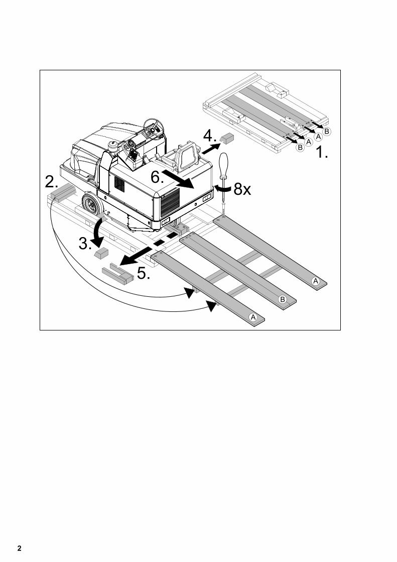
Ground clearance 70 mm. If the machine is delivered on a pallet,
you must create an unloading ramp us-ing the boards provided. You will find the instructions for this pro-cedure on page 2 (inside of cover).Important instruction: every board must be attached with at least 2 screws.
� DangerRisk of injury, risk of damage!� DangerRisk of injury!Danger of tipping if gradient is too high.– The gradient in the direction of travel
should not exceed 18%.Danger of tipping when driving round bends at high speed.– Drive slowly when cornering.Danger of tipping on unstable ground.– Only use the machine on sound surfac-
es.Danger of tipping with excessive sideways tilt.– The gradient perpendicular to the direc-
tion of travel should not exceed 10%.– It is important to follow all safety instruc-
tions, rules and regulations applicable for driving motor vehicles.
– The operator must use the appliance properly. He must consider the local conditions and must pay attention to third parties, in particular children, when working with the appliance.
– The appliance may only be used by per-sons who have been instructed in han-dling the appliance or have proven qualification and expertise in operating the appliance or have been explicitly assigned the task of handling the appli-ance.
– The appliance must not be operated by children, young persons or persons who have not been instructed accord-ingly.
– It is strictly prohibited to take co-pas-sengers.
– Ride-on appliances may only be started after the operator has occupied the driv-er's seat.
Please remove the ignition key, when not in use, to avoid unauthorised use of the appliance.
Never leave the machine unattended so long as the engine is running. The operator may leave the appliance only when the engine has come to a stand-still, the appliance has been protected against accidental movement, if neces-sary, by applying the immobilization brake and the ignition key has been re-moved.
� DangerRisk of injury!– Do not close the exhaust. – Do not bend over the exhaust or touch
it (risk of burns). – Do not touch the drive motor (risk of
burns). – Exhaust gases are poisonous and haz-
ardous to health, do not inhale them. – The engine requires approx. 3-4 sec-
onds to come to a standstill once it has been switched off. During this time, stay well clear of the working area.
– In emergencies, destroy the windows with a hammer.
NoteThe emergency hammer is located in the foot area, underneath the driver seat.
– Only use accessories and spare parts which have been approved by the man-ufacturer. The exclusive use of original accessories and original spare parts ensures that the appliance can be oper-ated safely and troublefree.
– At the end of the operating instructions you will find a selected list of spare parts that are often required.
– For additional information about spare parts, please go to the Service section at www.kaercher.com.
Hauptverband der gewerblichen Beruf-sgenossenschaften e.V. (HVBG / Germa-ny). Liquified gases (propellants) are butane and propane or a mixture of butane/propane. They are available in special cyl-inders. The operating pressure of these gases depends on the outside tempera-ture. � DangerRisk of explosion! Do not handle liquified gas like petrol. Petrol evaporates slowly, liquified gas immediately turns into gas. The risk of gas spreading in the room and getting ignited is thus higher in case of liq-uefied gas than in petrol.� DangerRisk of injury! Use only liquefied gas cylin-ders with propellant filled according to DIN 51622 of A or B quality, depending on the surrounding temperature.CautionUse of cooking gas is strictly prohibited. For the gas engine, use only liquid gas mix-tures of propane/ butane or their mixtures where the mixing ratio lies between 90/10 to 30/70. On account of better cold start be-haviour even at low outside sub-zero tem-peratures (below 0° C / 32 °F) always prefer a mixture with a higher propane share because evaporation takes place even at low temperatures.
– All persons handling liquid gases are li-able to acquaint themselves with the special properties of the liquefied gases for hazard-free handling of operations. The current documentation is always to be kept with the sweeper.
Contents
Safety instructions . . . . . . . EN . . 1Function . . . . . . . . . . . . . . . EN . . 3Proper use . . . . . . . . . . . . . EN . . 3Environmental protection . . EN . . 3Operating and Functional Ele-ments . . . . . . . . . . . . . . . . . EN . . 4Before Startup. . . . . . . . . . . EN . . 5Start up . . . . . . . . . . . . . . . . EN . . 5Operation . . . . . . . . . . . . . . EN . . 6Transport. . . . . . . . . . . . . . . EN . . 7Storage . . . . . . . . . . . . . . . . EN . . 7Shutdown . . . . . . . . . . . . . . EN . . 7Maintenance and care . . . . EN . . 7EC Declaration of Conformity EN . 12Warranty . . . . . . . . . . . . . . . EN . 12Troubleshooting . . . . . . . . . EN . 13Technical specifications . . . EN . 14
Safety instructions
General notes
Unloading tips
Unladen weight (without attach-ment sets)
900 kg *
* If upgrade kits are installed, the weight is respectively higher.
Drive mode
Appliances with combustion engine
Machines with driver cabin
Accessories and Spare Parts
Safety regulations for LPG vehicles
Liabilities of the factory management and the employee
3EN
- 2
– Propellant-operated units are to be checked at regular intervals, at least once a year, by an expert against leaks (according to BGG 936) and ensure that the unit is functioning properly.
– The inspection must be certified and documented. The inspection guidelines are § 33 and § 37 UVV (occupation ac-cident prevention regulations) "Use of liquid gas" (BGV D34).
– General applicable regulations are the guidelines for inspecting vehicles whose engines are driven by liquefied gases of the Federal Transportation Minister.
– Gas must always be drawn only from one cylinder. Drawing gas from multiple cylinders simultaneously can cause liq-uid gas from one cylinder flowing into the other. This causes the over-filled cylinder to be subjected to an unpermit-ted excess pressure when the cylinder valve is closed later (refer B.1 of these guidelines).
– Ensure the correct positioning of the cylinder with the "bottom" marking while connecting a full cylinder (the connec-tion screw points vertically downward).
Replace cylinders carefully. While connect-ing and disconnecting the gas cylinders, the gas outlets of the cylinder valve must be closed properly by tightening the locking nuts with a spanner. – Discontinue the use of leaky gas cylin-
ders. Such cylinders are to be emptied by slowly letting out the gas in open spaces by conforming to all safety reg-ulations and are to be indicated as leaky. Also inform the issuing company or its representative (the filling-station attendant) in writing about the damage to the cylinder while delivering or re-ceiving the cylinders.
– Before connecting the gas cylinder, check that its connection neck is in a proper state.
– After connecting the cylinder, regularly check that it is not leaky by using a foaming agent.
– Open the valves slowly. Do not use hammers to open and close the cylin-ders.
– Fight liquid-gas fires only from a safe distance and with protection.- use only dry powder carbon dioxide extinguishers or carbon dioxide gas ex-tinguishers.- use abundant water to cool the gas tank.
– The entire LPG unit must be continu-ously checked to ensure that there are no leaks and the unit is functioning properly. Using the vehicle with a leaky gas unit is strictly prohibited.
– First close the cylinder valve before loosening the pipe or tube connection. Unscrew and loosen the connection nut of the gas cylinder slowly because oth-erwise the gas under pressure in the tube will flow out instantly.
– If the gas is refilled from a larger tank, then ask the sales agent of the LPG about the important regulations to be followed.
� DangerRisk of injury!– LPG in a liquid state can cause frost
bites on bare skin. – After disconnecting the cylinder, tighten
the closing nut firmly on the connecting threading of the cylinder.
– Use soap water or some such foaming agent to check whether the cylinder is leaking. The use of open flames to illu-minate the LPG unit is strictly prohibit-ed.
– Follow the manufacturer's installation specifications while changing individual parts of the LPG unit. Close all cylinder and locking valves while doing so.
– Regularly check the status of the elec-trical unit of the LPG vehicles . Sparks can cause explosions if the gas-carry-ing parts of the unit are leaky.
– If a LPG-driven vehicle has been idling for a long time, then first ventilate the setting room before commissioning the vehicle or its electrical unit.
– Immediately inform the trade associa-tion and the concerned trade superviso-ry authority about accidents with gas cylinders or LPG units. Store the dam-aged parts carefully until all investiga-tions have been completed.
– Propellants or LPG cylinders must al-ways be stored according to the regula-tions of TRF 1996 (Technical Regulations for Liquid Gases, refer DA to BGV D34, Appendix 4).
– Always store the gas cylinders in a ver-tical position. Use of open flames and smoking at the installation site of the cylinders and during repairs is strictly prohibited. Protect the stored cylinders against unauthorised access. Close all empty cylinders properly.
– Close the cylinder and main locking valves immediately when you switch off the vehicle.
– Follow the regulations for garages and the construction guidelines of the re-spective State about the location and structure of the parking areas for LPG-driven vehicles.
– Gas cylinders are to be stored in sepa-rate rooms away from the parking areas (refer DA to BGV D34, Appendix 2).
– The electrical hand-held lamps used in the rooms are to be equipped with closed, sealed case and a strong pro-tection cover.
– Close all cylinder and main valves be-fore working in repair workshops and protect the gas cylinders against effect of external heat.
– A responsible person must check that all valves, especially the cylinder valves, are closed during operational breaks and before closing the factory. Do not carry out any jobs involving fire - such as cutting and welding jobs - in the vicinity of the gas cylinders. Do not store gas cylinders, not even empty ones, in the workshops.
– The parking and storage rooms and the repair workshops must be ventilated properly. Please note that liquefied gas-es are heavier than atmospheric air. They get collected on the floor, in re-cesses and other holes in the floors and form a gas-air mixture that can lead to explosions.
Maintenance by expert
Commissioning/Operations
In the installation and storage rooms as well as the workshops
4 EN
- 3
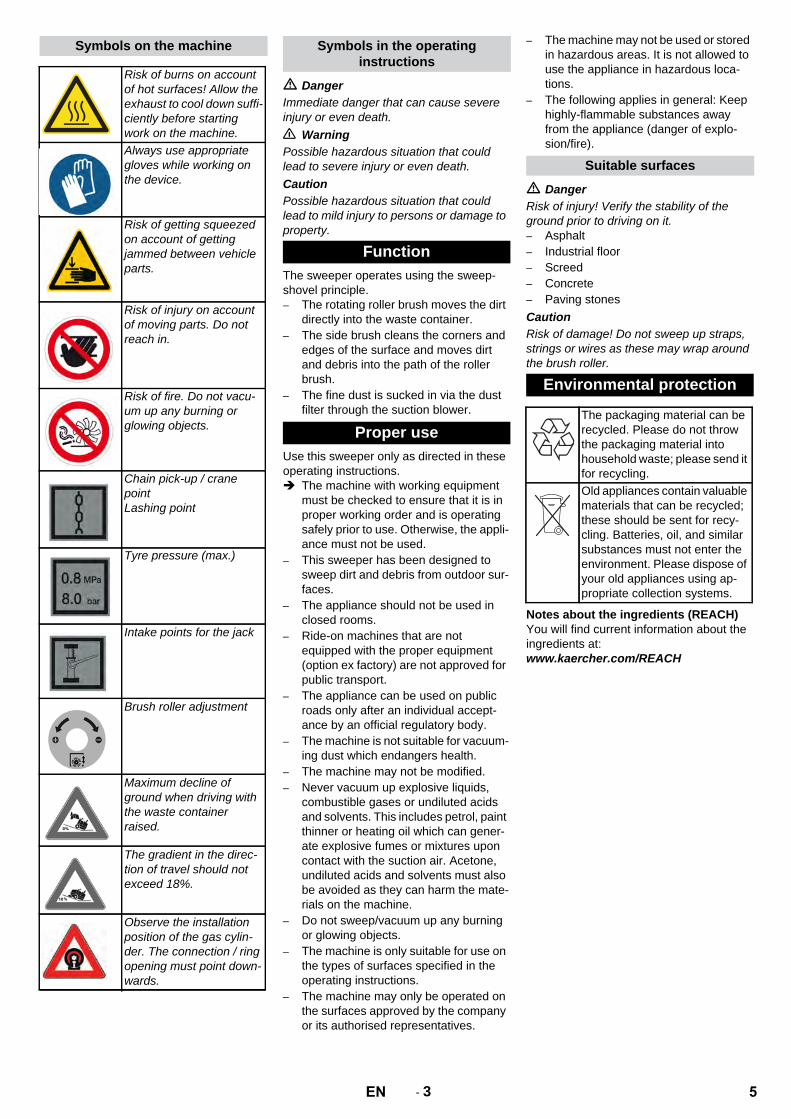
� DangerImmediate danger that can cause severe injury or even death.� WarningPossible hazardous situation that could lead to severe injury or even death.CautionPossible hazardous situation that could lead to mild injury to persons or damage to property.
The sweeper operates using the sweep-shovel principle.– The rotating roller brush moves the dirt
directly into the waste container.– The side brush cleans the corners and
edges of the surface and moves dirt and debris into the path of the roller brush.
– The fine dust is sucked in via the dust filter through the suction blower.
Use this sweeper only as directed in these operating instructions. The machine with working equipment
must be checked to ensure that it is in proper working order and is operating safely prior to use. Otherwise, the appli-ance must not be used.
– This sweeper has been designed to sweep dirt and debris from outdoor sur-faces.
– The appliance should not be used in closed rooms.
– Ride-on machines that are not equipped with the proper equipment (option ex factory) are not approved for public transport.
– The appliance can be used on public roads only after an individual accept-ance by an official regulatory body.
– The machine is not suitable for vacuum-ing dust which endangers health.
– The machine may not be modified.– Never vacuum up explosive liquids,
combustible gases or undiluted acids and solvents. This includes petrol, paint thinner or heating oil which can gener-ate explosive fumes or mixtures upon contact with the suction air. Acetone, undiluted acids and solvents must also be avoided as they can harm the mate-rials on the machine.
– Do not sweep/vacuum up any burning or glowing objects.
– The machine is only suitable for use on the types of surfaces specified in the operating instructions.
– The machine may only be operated on the surfaces approved by the company or its authorised representatives.
– The machine may not be used or stored in hazardous areas. It is not allowed to use the appliance in hazardous loca-tions.
– The following applies in general: Keep highly-flammable substances away from the appliance (danger of explo-sion/fire).
� DangerRisk of injury! Verify the stability of the ground prior to driving on it.– Asphalt– Industrial floor– Screed– Concrete– Paving stonesCautionRisk of damage! Do not sweep up straps, strings or wires as these may wrap around the brush roller.
Notes about the ingredients (REACH)You will find current information about the ingredients at: www.kaercher.com/REACH
Symbols on the machine
Risk of burns on account of hot surfaces! Allow the exhaust to cool down suffi-ciently before starting work on the machine.Always use appropriate gloves while working on the device.
Risk of getting squeezed on account of getting jammed between vehicle parts.
Risk of injury on account of moving parts. Do not reach in.
Risk of fire. Do not vacu-um up any burning or glowing objects.
Chain pick-up / crane pointLashing point
Tyre pressure (max.)
Intake points for the jack
Brush roller adjustment
Maximum decline of ground when driving with the waste container raised.
The gradient in the direc-tion of travel should not exceed 18%.
Observe the installation position of the gas cylin-der. The connection / ring opening must point down-wards.
Symbols in the operating instructions
Function
Proper use
Suitable surfaces
Environmental protection
The packaging material can be recycled. Please do not throw the packaging material into household waste; please send it for recycling.Old appliances contain valuable materials that can be recycled; these should be sent for recy-cling. Batteries, oil, and similar substances must not enter the environment. Please dispose of your old appliances using ap-propriate collection systems.
5EN

- 4
1 Driver cabin (optional)2 Cabin door (option)3 Tank lid4 Lashing point (4x)5 Roller brush access6 Front wheel7 Side brushes8 Lighting system (optional)9 Waste container10 Lock of appliance hood11 Windshield wiper (option)12 Engine cover13 Gas cylinder14 Cab lock15 Beacon lamp16 Centrifugal separator17 Lock lever of cab18 Brush roller adjustment (not pictured)
1 Programme switch2 Function keys3 Multifunction display4 Fuse box - work station5 Steering wheel6 Ignition lock7 Parking brake8 Motor speed adjustment9 Seat (with seat contact switch)10 Brake pedal11 Drive pedal
1 Warning blinking switch (option)2 Ignition key– Position 0: Switch off engine– Position 1: Ignition on– Position 2: Start the engine
1 Work lights on/off (option)2 Beacon lamp on/off3 Horn4 Filter dedusting5 Blinker switch6 Irrigation of side brush (optional)7 Blower8 Open/close container lid9 Raise/lower waste container
Operating and Functional Elements
Illustration of sweeper Operating field Ignition lock
Function keys
6 EN
- 5
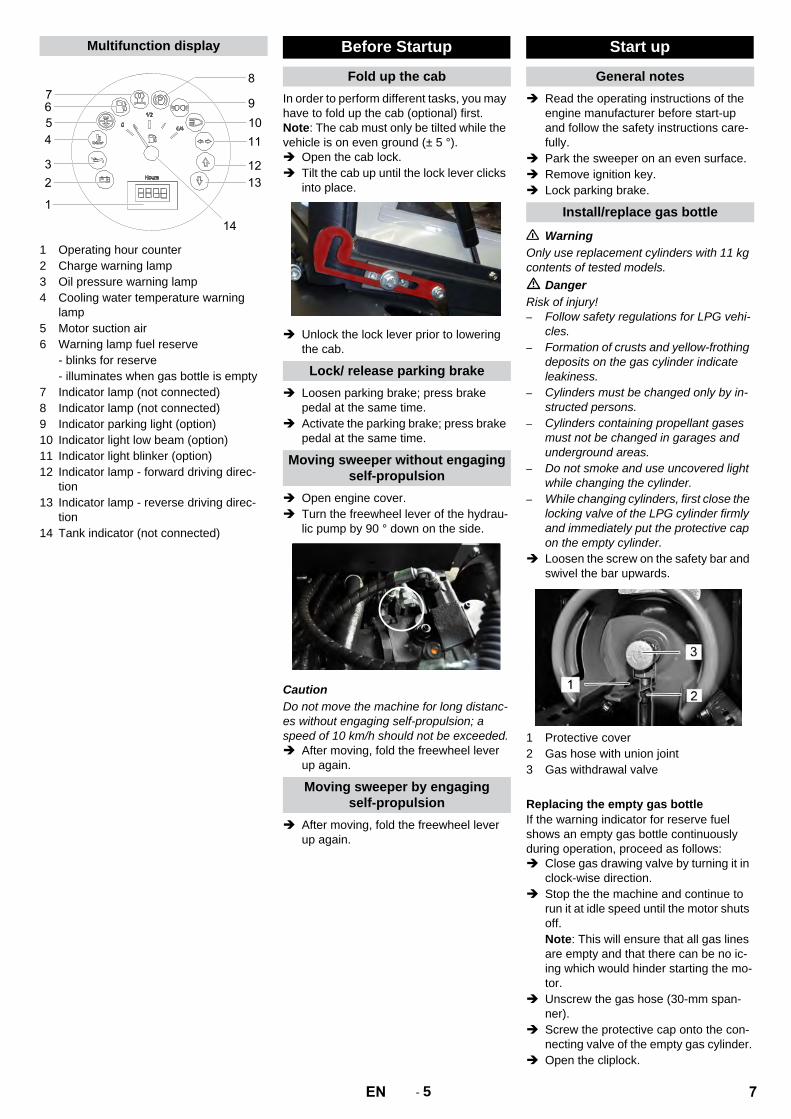
1 Operating hour counter2 Charge warning lamp3 Oil pressure warning lamp4 Cooling water temperature warning
lamp5 Motor suction air6 Warning lamp fuel reserve
- blinks for reserve- illuminates when gas bottle is empty
7 Indicator lamp (not connected)8 Indicator lamp (not connected)9 Indicator parking light (option)10 Indicator light low beam (option)11 Indicator light blinker (option)12 Indicator lamp - forward driving direc-
tion13 Indicator lamp - reverse driving direc-
tion14 Tank indicator (not connected)
In order to perform different tasks, you may have to fold up the cab (optional) first.Note: The cab must only be tilted while the vehicle is on even ground (± 5 °). Open the cab lock. Tilt the cab up until the lock lever clicks
into place.
Unlock the lock lever prior to lowering the cab.
Loosen parking brake; press brake pedal at the same time.
Activate the parking brake; press brake pedal at the same time.
Open engine cover. Turn the freewheel lever of the hydrau-
lic pump by 90 ° down on the side.
CautionDo not move the machine for long distanc-es without engaging self-propulsion; a speed of 10 km/h should not be exceeded. After moving, fold the freewheel lever
up again.
After moving, fold the freewheel lever up again.
Read the operating instructions of the engine manufacturer before start-up and follow the safety instructions care-fully.
Park the sweeper on an even surface. Remove ignition key. Lock parking brake.
� WarningOnly use replacement cylinders with 11 kg contents of tested models. � DangerRisk of injury!– Follow safety regulations for LPG vehi-
cles. – Formation of crusts and yellow-frothing
deposits on the gas cylinder indicate leakiness.
– Cylinders must be changed only by in-structed persons.
– Cylinders containing propellant gases must not be changed in garages and underground areas.
– Do not smoke and use uncovered light while changing the cylinder.
– While changing cylinders, first close the locking valve of the LPG cylinder firmly and immediately put the protective cap on the empty cylinder.
Loosen the screw on the safety bar and swivel the bar upwards.
1 Protective cover2 Gas hose with union joint3 Gas withdrawal valve
If the warning indicator for reserve fuel shows an empty gas bottle continuously during operation, proceed as follows: Close gas drawing valve by turning it in
clock-wise direction. Stop the the machine and continue to
run it at idle speed until the motor shuts off.Note: This will ensure that all gas lines are empty and that there can be no ic-ing which would hinder starting the mo-tor.
Unscrew the gas hose (30-mm span-ner).
Screw the protective cap onto the con-necting valve of the empty gas cylinder.
Open the cliplock.
Multifunction display Before Startup
Fold up the cab
Lock/ release parking brake
Moving sweeper without engaging self-propulsion
Moving sweeper by engaging self-propulsion
Start up
General notes
Install/replace gas bottle
Replacing the empty gas bottle
7EN

- 6
Replace the gas cylinder.Observe the installation position of the gas cylinder. The connection / ring opening must point downwards.
Unscrew the protective cap from the connecting valve of the gas cylinder.
Close the bracket closure. Screw the gas hose to the connecting
valve of the gas cylinder (30-mm span-ner).
Close the safety bar, and secure it with a bolt.
NoteConnection has a left threading. � WarningOpen the gas drawing valve (3) only after starting the appliance (refer chapter Start-ing the appliance).
Check engine oil level. Check the water cooler. Check roller brush. Check tyre pressure. Adjust driver's seat. Shake off dust filter.Note: For description, see section on Care and maintenance.
� DangerLong hours of using the appliance can cause circulation problems on account of vibrations.It is not possible to specify a generally valid operation time, since this depends on sev-eral factors:– Proneness to blood circulation deficien-
cies (frequently cold extremities, tin-gling, numbness).
– Low ambient temperature. Wear warm clothes to protect the affected body parts.
– A firm grip impedes blood circulation.– Continuous operation is worse than an
operation interrupted by pauses.In case of regular, long-term operation of the device and in case of repeated occur-rence of the symptoms (e.g. tingling, numb-ness in certain body parts) please consult a physician.
Pull seat adjustment lever outwards. Slide seat, release lever and lock in
place. Check that the seat is properly locked in
position by attempting to move it back-wards and forwards.
You can use the accelerator to regulate the engine speed.
1 Transport drive2 Sweeping with sweep roller3 Sweeping using roller brush and side
brushes
Note: The machine is equipped with a seat contact switch If the driver's seat is vacat-ed, the machine is switched off.
Open the gas drawing valve by turning it in anti-clockwise direction.
Sit on the driver's seat. Bring the direction selector switch into
the middle position. Lock parking brake. Engine speed adjustment - push for-
ward by 1/3.
Insert the ignition key into the ignition lock.
Turn the ignition key to position "II". If the machine starts, release the igni-
tion key.Note: Never operate the starter motor for longer than 10 seconds. Wait at least 10 seconds before operating the starter motor again.
Set programme selection switch to "Transport drive". .
Move the gas lever all the way to the front (high speed).Note: The speed of the side brush and the brush roller depends on the motor speed.
Press brake pedal and keep it de-pressed.
Release parking brake.
Set the travel direction switch to "for-ward".
Press accelerator pedal down slowly.
� DangerRisk of injury! While reversing, ensure that there is nobody in the way, ask them to move if somebody is around.CautionRisk of damage! Only use the direction switch when the machine is standing still. Set the travel direction switch to "back-
wards". Press accelerator pedal down slowly.
– The accelerator pedal can be used to vary the driving speed infinitely.
– Avoid pressing the pedal suddenly as this may damage the hydraulic system.
– In the event of power loss on inclined surfaces, slightly reduce the pressure on the accelerator pedal.
Release the accelerator pedal, the ma-chine brakes automatically and stops.
Note: The braking effect can be supported by pressing the brake pedal.
Driving over fixed obstacles which are 70 mm high or less: Drive forwards slowly and carefully.Driving over fixed obstacles which are more than 70 mm high: Only drive over these obstacles using a
suitable ramp.
CautionDo not sweep up packing strips, wire or similar objects as this may damage the sweeping mechanism.Note: To achieve an optimum cleaning re-sult, the driving speed should be adjusted to take specific situations into account.Note: During operation, the waste contain-er should be emptied at regular intervals.Note: During operation, the dust filter should be shaken off and cleaned at regu-lar intervals.
Installing a new gas bottle
Inspection and maintenance work
Operation
Adjusting driver's seat
Adjust engine speed
Programme selection
Starting the machine
Open the gas supply
Start the engine
Drive the machine
Drive forward
Reverse drive
Driving method
Brakes
Driving over obstacles
Sweeping mode
8 EN

- 7
Switch on the blower.
Set the programme switch to sweep with sweeping brush when cleaning surfaces.
Set the programme switch to sweep with sweeping brush and side brush when cleaning edges.
Switch off the blower. Set the programme switch to sweep
with sweeping brush when cleaning surfaces.
Set the programme switch to sweep with sweeping brush and side brush when cleaning edges.
� DangerRisk of injury! When emptying the waste container, care should be taken to ensure that no persons or animals are within its swivelling range.� DangerDanger of crushing. Never reach into the rod assembly for the drainage mechanism. Stay away from the area under the raised container.� DangerDanger of tipping. Place the machine on an even surface during emptying.
Set programme selection switch to "Transport drive". .
Raise waste container.
Slowly drive towards the collection con-tainer.
Lock parking brake. Open the container door: Press the left
side of the switch and empty the waste container.
Close the container door: Press the right side of the switch (approximately 2 seconds), until the unit is tilted to the end position.
Release parking brake. Drive away the collection container
slowly. Lower the waste container up to the
end-position.
Push the motor speed adjustment all the way to the rear.
Press brake pedal and keep it de-pressed.
Lock parking brake. Turn ignition key to "0" and remove it.
Close gas drawing valve by turning it in clock-wise direction.
� DangerRisk of injury and damage! Observe the weight of the appliance when you transport it. Turn ignition key to "0" and remove it. Lock parking brake. Secure the appliance at the lashing
points (4x) using tension belts, ropes or chains.
Secure the wheels of the machine with wheel chocks.
When transporting in vehicles, secure the appliance according to the guide-lines from slipping and tipping over.
� DangerRisk of injury and damage! Note the weight of the appliance in case of storage.
If the sweeper is going to be out of service for a longer time period, observe the follow-ing points: Park the sweeper on an even surface. Raise the roller brush and the side-
brushes to prevent the bristles from be-ing damaged.
Turn ignition key to "0" and remove it. Lock parking brake. Lock the sweeper to ensure that it does
not roll off. Change engine oil. Drain off the cooling water if frost is ex-
pected and check whether there is ade-quate anti-frosting agent.
Clean the inside and outside of the sweeper.
Charge the battery and clamp it off. Close the gas inlet. Unscrew the gas hose with union nut
(use 30 mm spanner). Lock the gas bottle with the safety cap
and store upright in a suitable storage area (also see Chapter "Safety instruc-tions).
– Maintenance work may only be carried out by approved customer service out-lets or experts in this field who are famil-iar with the respective safety regulations.
– Mobile appliances used for commercial purposes are subject to safety inspec-tions according to VDE 0701.
Park the sweeper on an even surface. Turn ignition key to "0" and remove it. Lock parking brake.
CautionRisk of damage! Do not clean the appliance with a water hose or high-pressure water jet (danger of short circuits or other dam-age).
� DangerRisk of injury! Wear dust mask and protec-tive goggles. Clean machine with a cloth. Blow through machine with com-
pressed air.
Clean the machine with a damp cloth which has been soaked in mild deter-gent.
Note: Do not use aggressive cleaning agents.
Sweeping dry floors
Sweeping damp or wet floors
Emptying waste container
Turn off the appliance
Close the gas inlet
Transport
Storage
Shutdown
Maintenance and care
General notes
Cleaning
Cleaning the inside of the machine
External cleaning of the appliance
9EN
- 8
Observe the inspection checklist 5.950-647.0!Note: The elapsed-time counter shows the timing of the maintenance intervals.
Note: Where maintenance is carried out by the customer, all service and maintenance work must be undertaken by a qualified specialist. If required, a specialised Kärch-er dealer may be contacted at any time.Daily maintenance: Check engine oil level. Check cooler water level. Check tyre pressure. Check the sweeping roller and the side
brush for wear and wrapped belts. Check the wheels for tied up belts. Check the centrifugal separator and the
air filter, clean if required. Check function of all operator control el-
ements. Check appliance for damages.Weekly maintenance: Clean the water cooler. Clean the hydraulic oil cooler. Check hydraulic unit. Check the hydraulic oil level. Check brake fluid status. Check the pad for wear, replace if re-
quired. Check the container lid and lubricate it.Maintenance following wear: Replace sealing strips. Replace roller brush. Replace side brush.Note: For description, see section on Main-tenance work.
Note: In order to safeguard warranty claims, all service and maintenance work during the warranty period must be carried out by the authorised Kärcher Customer Service in accordance with the mainte-nance booklet.Maintenance to be carried out after 50 operating hours: Have the first inspection done accord-
ing to the service manual.Maintenance to be carried out after 250 operating hours: Have the inspection done according to
the service manual.
Preparation: Park the sweeper on an even surface. Turn ignition key to "0" and remove it. Lock parking brake. Close the gas inlet.
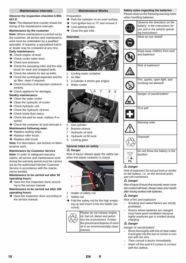
1 Cooling water container2 Air filter3 3-Cylinder 4-stroke gas engine4 Water cooler
5 Gas cylinder6 Bracket closure7 Hydraulic oil tank8 Hydraulic oil fill neck9 Looking glass
� DangerRisk of injury! Always apply the safety bar when the waste container is raised.
1 Holder of safety rod2 Safety rod Fold the safety rod for the high empty-
ing up and insert it into the holder (se-cured).
Please observe the following warning notes when handling batteries:
� DangerRisk of explosion! Do not put tools or similar on the battery, i.e. on the terminal poles and cell connectors.� DangerRisk of injury! Ensure that wounds never come into contact with lead. Always clean your hands after having worked with batteries.� DangerRisk of fire and explosion!– Smoking and naked flames are strictly
prohibited. – Rooms where batteries are charged
must have good ventilation because highly explosive gas is emitted during charging.
� DangerDanger of causticization!– Rinse thoroughly with lots of clear water
if acid gets into the eye or comes in con-tact with the skin.
– Then consult a doctor immediately.– Wash off the acid If it comes in contact
with the clothes.
Maintenance intervals
Maintenance by the customer
Maintenance by Customer Service
Maintenance Works
Overview
General notes on safety
Please do not release engine oil, fuel oil, diesel and petrol into the environment. Protect the ground and dispose of used oil in an environmentally-clean manner.
Safety notes regarding the batteries
Observe the directions on the battery, in the instructions for use and in the vehicle operat-ing instructions!Wear an eye shield!
Keep away children from acid and batteries!
Risk of explosion!
Fire, sparks, open light, and smoking not allowed!
Danger of causticization!
First aid!
Warning note!
Disposal!
Do not throw the battery in the dustbin!
10 EN

- 9
Insert battery in battery mount. Screw on mounts on battery base. Connect pole terminal (red cable) to
positive pole (+). Connect pole terminal to negative pole
(-).Note: Check that the battery pole and pole terminals are adequately protected with pole grease.
CautionRegularly check the fluid level in acid-filled batteries.– The acid in a fully charged battery has a
specific weight of 1.28 kg/l at a temper-ature of 20 °C.
– The acid in a partially discharged bat-tery has a specific weight between 1.00 and 1.28 kg/l.
– The specific weight of the acid must be uniform in all cells.
Unscrew all cell caps. Take a sample from each cell using the
acid tester. Put the acid sample back into the same
cell. Where fluid level is too low, top up cells
to the mark provided with distilled wa-ter.
Charge battery. Screw in cell caps.
� DangerRisk of injury! Comply with safety regula-tions on the handling of batteries. Observe the directions provided by the manufacturer of the charger.� DangerCharge the battery only with an appropriate charger.
Unscrew all cell caps. Connect positive terminal cable from
the charger to the positive pole connec-tion on the battery.
Connect negative terminal cable from the charger to the negative pole con-nection on the battery.
Plug in mains connector and switch on charger.
Charge battery using lowest possible level of charging current.
Note: When the battery is charged, first re-move the charger from the mains and then disconnect it from the battery.
Disconnect pole terminal to negative pole (-).
Disconnect pole terminal to positive pole (-).
Loosen the mounts on battery base. Remove the battery from the battery
holder. Dispose of the used battery according
to the local provisions.
� DangerRisk of burns! Allow engine to cool down. Wait for at least 5 minutes after switch-
ing off the engine before checking the engine oil fill level.
1 Oil dipstick2 Screw cap, oil fill opening
Pull out oil dipstick. Wipe off oil dipstick and insert. Pull out oil dipstick. Read the value of the oil level. Insert the oil dip again.
– The oil level must lie between “MIN“ and “MAX“ marking.
– Add motor oil if the oil level is below the "MIN" marking.
– Do not fill oil above the "MAX" marking. Loosen the closing cap of the oil filling
opening. Fill in motor oil.
Oil grade: see Technical Data Close oil filler opening. Wait at least 5 minutes. Check engine oil level.
CautionRisk of burns due to hot oil! Ready a catch bin for approx. 6 litre oil. Allow engine to cool down.
1 Oil drain screw
Unscrew oil drain plug. Loosen the screw cap of the oil filling
opening. Drain off oil.
1 Oil filter motor
Unscrew the oil filter. Clean the intake and sealing areas. Coat the washer of the new oil filter with
oil before fitting it. Fit in the new oil filter and tighten it by
hand. Screw in the oil drain screw along with
the new washer.Note: Tighten the oil drain screw using a torque wrench to 25 Nm. Fill in motor oil.Oil grade: see Technical Data Close oil filler opening. Let the motor run for approx. 10 sec-
onds. Check engine oil level.
Installing and connecting the battery
Check fluid level in the battery and ad-just if required
Charging battery
Remove the battery
Check engine oil level and top up, if re-quired
Change the motor oil and the oil filter
11EN

- 10
NoteThe waste container must not be raised. Open engine cover.
1 Looking glass2 Manometer3 Screw cap, oil fill opening
Check hydraulic oil level in the looking glass.
– The oil level must lie between “MIN“ and “MAX“ marking.
– Add hydraulic oil if the oil level is below the "MIN" marking.
Loosen the closing cap of the oil filling opening.
Clean the filling area. Refill hydraulic oil.
Oil grade: see Technical Data Replace and tighten the closing cap of
the oil filling opening.NoteIf the pressure gauge shows an increased hydraulic oil pressure, the hydraulic oil filter must be replaced by Kärcher customer ser-vice.
Lock parking brake. Start the motor. Only Kärcher Customer Service is author-ised to carry out maintenance tasks on the hydraulic unit. Check all hydraulic hoses and connec-
tions and ensure that they are leak-proof.
� DangerDanger of scalding by boiling water! Let the cooler cool down for at least 20 minutes. Check the cooling water level on the
balance reservoir (water level between MIN and MAX).
Clean cooler lamella. Check cooler hoses and connections
and ensure that they are leak-proof. Clean the fan.
Start the motor. Raise the waste container up to the
end-position. Switch off engine. Lock parking brake. Use the safety bar for emptying from a
height. Remove belts or cords from roller
brush. Remove the safety bar. Start the motor. Lower the waste container up to the
end-position. Switch off engine.
1 Fastening screws of the roller brush in-take
2 Roller brush3 Roller brush intake4 Holding plate for side seal5 Side seal
Open the side covers using a key. Unscrew the wingnuts from the holding
plate side seals and remove the holding plate.
Flip the side seal out. Uncscrew the retaining screw of the
roller brush intake, and swing the intake to the outside.
Pull out roller brush.
Installation position of roller brush in direc-tion of travel (top view)Note: When installing the new roller brush, ensure correct positioning of the bristle as-sembly.
Install new roller brush. The nuts of the roller brush must be inserted on the notches of the opposite crank.
Note: Once the new roller brush has been installed, the sweeping track must readjust-ed.
Note: The sweeping track is factory-set to 80 mm; it is steplessly adjustable if the brush roller wears down. Check tyre pressure. Switch off suction blower. Drive sweeper on to a smooth, even
surface covered with a visible layer of dust or chalk.
Set the programme switch to sweep with roller brush.
Set programme selection switch to "Transport drive".
Drive machine backwards. Check sweeping mirror.
The sweeping track should have an even rectangular shape which is 80-85 mm wide.
1 Rating nut2 Counter-nut Open the side engine panel. Loosen counter-nut. Adjust sweeping track Tighten counter nut. Check the sweeping track of the sweep-
ing roller.
Check tyre pressure. The side-brushes lift up. Drive sweeper on to a smooth, even
surface covered with a visible layer of dust or chalk.
Set the programme switch to sweep with roller brush and side brush.
The side-brushes lift up. Set programme selection to "Drive". Drive machine backwards. Check sweeping mirror.
Check hydraulic oil level and refill hy-draulic oil
Check hydraulic unit
Check water cooler and maintain it
Checking roller brush
Replacing roller brush
Check and adjust roller brush sweeping track
Check and adjust sweeping track of the side-brush
12 EN
- 11
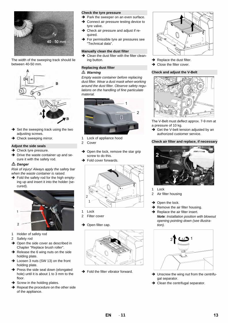
The width of the sweeping track should lie between 40-50 mm.
Set the sweeping track using the two adjusting screws.
Check sweeping mirror.
Check tyre pressure. Drive the waste container up and se-
cure it with the safety rod.� DangerRisk of injury! Always apply the safety bar when the waste container is raised. Fold the safety rod for the high empty-
ing up and insert it into the holder (se-cured).
1 Holder of safety rod2 Safety rod Open the side cover as described in
Chapter "Replace brush roller". Release the 6 wing nuts on the side
holding plate. Loosen 3 nuts (SW 13) on the front
holding plate. Press the side seal down (elongated
hole) until it is about 1 to 3 mm to the floor.
Screw in the holding plates. Repeat the procedure on the other side
of the appliance.
Park the sweeper on an even surface. Connect air pressure testing device to
tyre valve. Check air pressure and adjust if re-
quired. For permissible tyre air pressures see
"Technical data".
Clean the dust filter with the filter clean-ing button.
� WarningEmpty waste container before replacing dust filter. Wear a dust mask when working around the dust filter. Observe safety regu-lations on the handling of fine particulate material.
1 Lock of appliance hood2 Cover
Open the lock, remove the star grip screw to do this.
Fold cover forwards.
1 Lock2 Filter cover
Open filter cap.
Fold the filter vibrator forward.
Replace the dust filter. Close the filter cover.
The V-Belt must deflect approx. 7-9 mm at a pressure of 10 kg. Get the V-belt tension adjusted by an
authorized customer service.
1 Lock2 Air filter housing
Open the lock. Remove the air filter housing. Replace the air filter insert.
Note: Installation position with blowout opening pointing down (see illustra-tion).
Unscrew the wing nut from the centrifu-gal separator.
Clean the centrifugal separator.
Adjust the side seals
Check the tyre pressure
Manually clean the dust filter
Replacing dust filter
2
1
Check and adjust the V-Belt
Check air filter and replace, if necessary
13EN
- 12
Unscrew the head lamps. Take out the head lamps and pull out
the plug.Note: Note the positions of the plugs. Dismantle the head lamps. Dismantle the head lamp casing and
hold it horizontally because the lamp unit is not fastened.
Unlock the bracked and take out the bulb.
Insert new bulb. Reinstall in reverse sequence.
Note: Remove the glass of the direction-in-dicator lamp from its casing to replace the bulb.
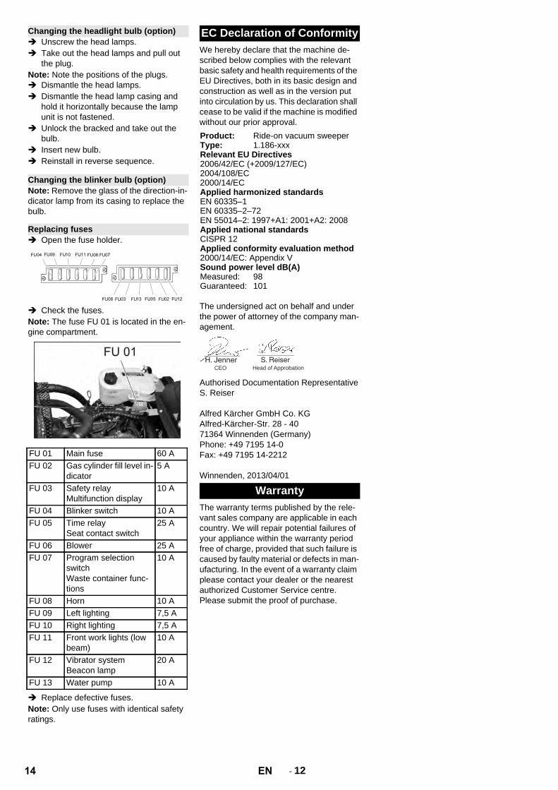
Open the fuse holder.
Check the fuses.Note: The fuse FU 01 is located in the en-gine compartment.
Replace defective fuses.Note: Only use fuses with identical safety ratings.
We hereby declare that the machine de-scribed below complies with the relevant basic safety and health requirements of the EU Directives, both in its basic design and construction as well as in the version put into circulation by us. This declaration shall cease to be valid if the machine is modified without our prior approval.
The undersigned act on behalf and under the power of attorney of the company man-agement.
Authorised Documentation RepresentativeS. Reiser
Alfred Kärcher GmbH Co. KGAlfred-Kärcher-Str. 28 - 4071364 Winnenden (Germany)Phone: +49 7195 14-0Fax: +49 7195 14-2212
Winnenden, 2013/04/01
The warranty terms published by the rele-vant sales company are applicable in each country. We will repair potential failures of your appliance within the warranty period free of charge, provided that such failure is caused by faulty material or defects in man-ufacturing. In the event of a warranty claim please contact your dealer or the nearest authorized Customer Service centre. Please submit the proof of purchase.
Changing the headlight bulb (option)
Changing the blinker bulb (option)
Replacing fuses
FU 01 Main fuse 60 AFU 02 Gas cylinder fill level in-
dicator 5 A
FU 03 Safety relayMultifunction display
10 A
FU 04 Blinker switch 10 AFU 05 Time relay
Seat contact switch25 A
FU 06 Blower 25 AFU 07 Program selection
switchWaste container func-tions
10 A
FU 08 Horn 10 AFU 09 Left lighting 7,5 AFU 10 Right lighting 7,5 AFU 11 Front work lights (low
beam)10 A
FU 12 Vibrator systemBeacon lamp
20 A
FU 13 Water pump 10 A
EC Declaration of Conformity
Product: Ride-on vacuum sweeperType: 1.186-xxxRelevant EU Directives2006/42/EC (+2009/127/EC)2004/108/EC2000/14/ECApplied harmonized standardsEN 60335–1EN 60335–2–72EN 55014–2: 1997+A1: 2001+A2: 2008Applied national standardsCISPR 12Applied conformity evaluation method2000/14/EC: Appendix VSound power level dB(A)Measured: 98Guaranteed: 101
Warranty
CEO Head of Approbation
14 EN

- 13
Troubleshooting
Fault RemedyAppliance cannot be started Sit on the driver seat, the seat contact switch gets activated.
Charging or replacing batteryGas bottle empty - replace gas bottle.Gas removal valve closed - open the valve by turning it in anti-clockwise direction.Gas valve iced - please read the description of the gas bottle replacement procedure.Inform Kärcher Customer Service.
Engine is running erratically Clean air filter or change filter cartridge.Check fuel pipes, connections and joints and maintain them if requiredInform Kärcher Customer Service.
Engine is overheated Refill coolantRinse coolerTighten V-BeltInform Kärcher Customer Service.
Engine is running but machine is only moving slowly or is not moving at all
Release parking brakeCheck for trapped ribbons and strings.Inform Kärcher Customer Service.
Whistling sound in the hydraulic system
Refill hydraulic fluidInform Kärcher Customer Service.
Brushes are rotating slowly or not at all
Move the gas lever all the way to the front (high speed).Check for trapped ribbons and strings.Inform Kärcher Customer Service.
Too little or no suction power in the brush area
Clean filterInform Kärcher Customer Service.
Dust gathers in the machine Adjust the side sealsSwitch on blowerClean dust filterReplace filter washersInform Kärcher Customer Service.
Sweeping unit does not pick up waste
Empty waste containerClean dust filterReplacing roller brushAdjust sweeping trackReplace sealing strips of the waste containerRemove the blocking of the brush rollerInform Kärcher Customer Service.
Waste container does not raise or lower
Check the fuses.Inform Kärcher Customer Service.
Waste container is rotating slowly or not at all
Inform Kärcher Customer Service.
Operation problems with hydraulic movement parts
Inform Kärcher Customer Service.
15EN
- 14
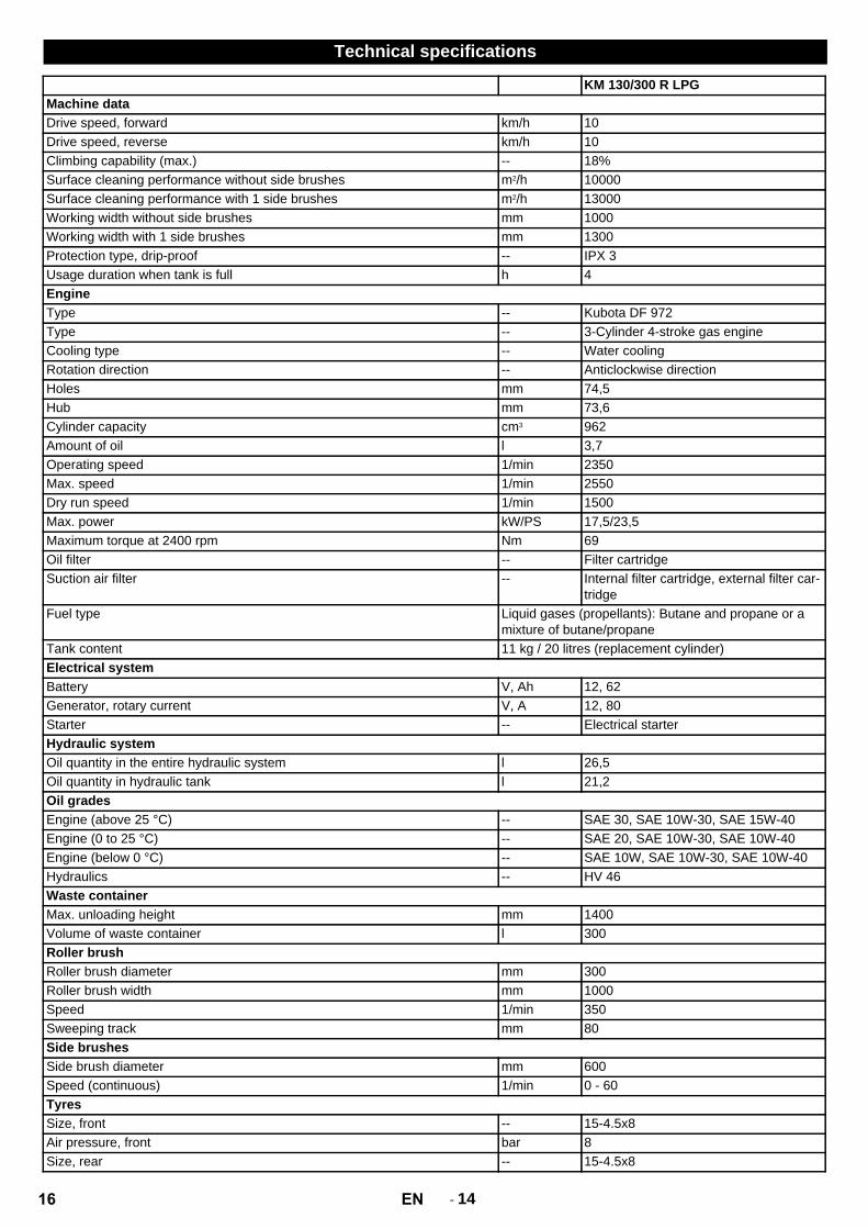
Technical specifications
KM 130/300 R LPGMachine dataDrive speed, forward km/h 10Drive speed, reverse km/h 10Climbing capability (max.) -- 18%Surface cleaning performance without side brushes m2/h 10000Surface cleaning performance with 1 side brushes m2/h 13000Working width without side brushes mm 1000Working width with 1 side brushes mm 1300Protection type, drip-proof -- IPX 3Usage duration when tank is full h 4EngineType -- Kubota DF 972Type -- 3-Cylinder 4-stroke gas engineCooling type -- Water coolingRotation direction -- Anticlockwise directionHoles mm 74,5Hub mm 73,6Cylinder capacity cm3 962Amount of oil l 3,7Operating speed 1/min 2350Max. speed 1/min 2550Dry run speed 1/min 1500Max. power kW/PS 17,5/23,5Maximum torque at 2400 rpm Nm 69Oil filter -- Filter cartridgeSuction air filter -- Internal filter cartridge, external filter car-
tridgeFuel type Liquid gases (propellants): Butane and propane or a
mixture of butane/propaneTank content 11 kg / 20 litres (replacement cylinder)Electrical systemBattery V, Ah 12, 62Generator, rotary current V, A 12, 80Starter -- Electrical starterHydraulic systemOil quantity in the entire hydraulic system l 26,5Oil quantity in hydraulic tank l 21,2Oil gradesEngine (above 25 °C) -- SAE 30, SAE 10W-30, SAE 15W-40Engine (0 to 25 °C) -- SAE 20, SAE 10W-30, SAE 10W-40Engine (below 0 °C) -- SAE 10W, SAE 10W-30, SAE 10W-40Hydraulics -- HV 46Waste containerMax. unloading height mm 1400Volume of waste container l 300Roller brushRoller brush diameter mm 300Roller brush width mm 1000Speed 1/min 350Sweeping track mm 80Side brushesSide brush diameter mm 600Speed (continuous) 1/min 0 - 60TyresSize, front -- 15-4.5x8Air pressure, front bar 8Size, rear -- 15-4.5x8
16 EN

- 15
BrakeFront wheels -- mechanicalRear wheel -- hydrostaticFilter and vacuum systemType -- Flat fold filterSpeed 1/min 2800Filter surface area, fine dust filter m2 5,2Nominal vacuum, suction system mbar 15,5Nominal volume flow, suction system m3/h 800Vibrator system -- Electric motorWorking conditionsTemperature °C -5 and +40Air humidity, non-condensing % 0 - 90Values determined as per EN 60335-2-72Noise emissionSound pressure level LpA dB(A) 80Uncertainty KpA dB(A) 3Sound power level LWA + Uncertainty KWA dB(A) 101Machine vibrationsHand-arm vibration value m/s2 1,9Seat m/s2 0,6Uncertainty K m/s2 0,1Dimensions and weightsLength x width x height mm 2040 x 1330 x 1430Right turning radius mm 1400Left turning radius mm 1400Unladen weight kg 900Permissible overall weight kg 1480Permissible front axle load kg 877Permissible rear axle load kg 603Subject to technical modifications!
17EN

http://www.kaercher.com/dealersearch