
Kitplanes November2015
84
POLE TO POLE IN A LANCAIR IV ® NOVEMBER 2015 www.kitplanes.com KITPLANES NOVEMBER 2015 Lady Bug RV-8 • Pole to Pole, Part 1 • Spirit of St. Louis Replica • Viperjet • Electrical Systems • Bearhawk Project • Airplane Washing • Carburetion • Using O2 BELVOIR PUBLICATIONS In the Shop: • More Floobydust • Bore Gauging • Going Off-Plans SPIRIT OF ST. LOUIS Remaking History CUSTOMER-BUILT VIPERJET First Of Its Kind ENGINE THEORY Carbed Induction CLEANING YOUR PLANE Doing It The Right Way Lady Bug Building a Winner
-
Upload
ahmad-usman -
Category
Documents
-
view
40 -
download
12
description
Amateur Home Build Magazine
Transcript of Kitplanes November2015

Pole to Pole in a lancair iV
®
NOVEMBER 2015
www.kitplanes.com
KITPLA
NESN
OVEM
BER2015LadyBugRV-8•PoletoPole,Part1•SpiritofSt.LouisReplica•Viperjet•ElectricalSystems•Bearhaw
kProject•AirplaneW
ashing•Carburetion•UsingO
2BELVO
IRPUBLIC
ATIONS
In the Shop: •MoreFloobydust•BoreGauging•GoingOff-Plans
Spirit of St. LouiS Remaking History
CuStomer-BuiLt Viperjet First Of Its Kind
engine theory Carbed InductionCLeaning your pLane Doing It The Right Way
Lady Bug Building a Winner


6
34
14
On the cover: Paul Berg’s RV-8, Lady Bug, photographed at AirVenture 2014 by Tyson V. Rininger. To see more of Tyson’s work, visit www.tvrphotography.com.
November 2015 | Volume 32, Number 11
KITPLANES November 2015 1
Flying Lifestyle6 Pole to Pole! Around the world over both poles (part 1).
By Bill Harrelson.
Builder Spotlight14 lady Bug’s story: Building a fastback RV-8 and winning
a Silver Lindy. By Paul Berg.
22 ViPerjet: 380 knots the hard way. By Dave Prizio.
26 Building the Bearhawk lsa: Working on the wings. By Ken Scott.
30 how to use your oxygen system: Things to know before you go. By Gary Jones.
34 sPirit of st. louis: John Norman’s definitive reproduction is virtually identical to the original. By David Gustafson.
44 engine theory: Carburetion. Getting air and fuel into the engine. By Tom Wilson.
66 ComPletions: Builders share their successes.
68 ask the dar: Certified aircraft converted to Experimental, ELSA vs. E/A-B, op lims for major changes. By Mel Asberry.
Shop Talk48 airCraft wiring: Good things to know while building your
electrical system. By Marc Ausman.
54 the new guy: Going off-plans. By David Boeshaar.
56 maintenanCe matters: A clean plane is a safer plane and a source of pride. By Dave Prizio.
63 home shoP maChinist: Bore gauging. By Bob Hadley.
78 aero ’leCtriCs: The last Floobydust. By Jim Weir.
Shop Tip59 eliminating egg-shaPed holes: By Larry Larson.
Designer’s Notebook40 stressing struCture: Bending. By David Paule.
75 wind tunnel: Stiffness. By Barnaby Wainfan.
Exploring2 editor’s log: The envelope, please. By Paul Dye.
52 CheCkPoints: Skills transference, part 1. By Vic Syracuse.
60 down to earth: Taking our instrument panel into the next decade. By Amy Laboda.
Kit Bits4 letters
69 list of adVertisers
70 Builders’ marketPlaCe
80 kit stuff: Drawing on experience. By cartoonist Robrucha.
For subscription information, contact KITPLANES® at 800/622-1065 or visit www.kitplanes.com/cs.

2 KITPLANES November 2015 www.kitplanes.com & www.facebook.com/kitplanes
The envelope, please.
Paul Dye retired as a Lead Flight Director for NASA’s Human Space Flight program, with 40 years of aerospace experience on everything from Cubs to the space shuttle. An avid homebuilder, he began flying and working on airplanes as a teen, and has experience with a wide range of construction techniques and materials. He flies an RV-8 that he built in 2005, and an RV-3 that he built with his pilot wife. Currently, they are building a Xenos motorglider. A commercially licensed pilot, he has logged over 4800 hours in many different types of aircraft. He consults and collaborates in aerospace operations and flight-testing projects across the country.
Paul Dye
Editor’s log
Seeing as how we’re all part of the Experimental aviation business here, let’s talk a little about test flying, shall we? Almost everyone who is building an airplane secretly dreams of the day they can swagger across the ramp in a leather jacket, carrying a parachute and a pack of Beeman’s, hop into their cockpit and depart in a blast of wind to challenge the demons of the blue while stretching the ol’ envelope a bit. At least, most everyone has that fantasy—at least once. Then we find that the reality of flight testing is just a little different. In fact, at times it can be downright boring.
Every aircraft with an Experimental air-worthiness certificate has to go through some sort of test period to determine its flying characteristics, performance num-bers, and yes—the edges of the envelope. Pilots have been taking new airplanes aloft since, well, the Wright brothers—but still the contents of a good test pro-gram are not always understood. You’d think that, by now, there’d be a book that provides an Experimental airplane builder with a step-by-step process for testing their new airplane. But as you’ve probably found out by now (if you’ve looked), there isn’t one that works in all cases. And the reason is, it’s complicated.
No two airplane designs are alike—that’s the first problem. What is impor-tant to test in a go-fast cross-country machine may not even be relevant in a tube-and-fabric local flyer. An air-plane that started out as a sketch on the builder’s breakfast napkin probably
has a little more testing that needs to be done than the 1500th RV-7 to take to the skies. The test program you need to fly is going to depend on a lot of things: the maturity of the design, the uses to which the airplane will be put, and how well you followed the designer’s instruc-tions on engines and weight.
Phase 1 is a test period required by the FAA—it might be 25 hours, it might be 40—but the contents are pretty much left up to the individual. AC 90-89 is a good guideline for getting the airplane safely through its first few flights—but it gets pretty vague after that. As a result, many builders simply go boring holes in the sky, flying off the hours by flying the same test hour 40 times, until they are released from their test box. And to be honest, for some airplanes, not a
lot is required. But for many others, this approach is sorely lacking.
The general progression of flight test-ing for a new aircraft is to first determine that it is controllable and reasonably stable within its normal operating regime, then turn to performance testing to get some basic numbers for stall, climb, glide and cruise, and then to start expanding the envelope in terms of stability and control at different weight and balance conditions and G-loadings. Systems testing (fuel, elec-trical, and avionics) is also important at this stage to make sure that the engine and essential equipment will keep operating under varying conditions. If the airplane is the first of its kind, most of this is unknown until proven, and part of the envelope expansion is also to determine the air-frame’s ability to withstand design loads.
You don’t have to be Chuck Yeager to test the average kit aircraft. Much of what you need to learn at the edges of the envelope has already been determined by the factory—assuming you stuck to the plans.

KITPLANES November 2015 3
With the advent of popular kit aircraft with thousands of examples flying, the need to do structural envelope testing on individual aircraft is much reduced—so long as the aircraft is built to match the design and plans. If the builder has made modifications to structure, changed the weight limits, installed more (or less) power—well, then more testing is going to be required, as they are once again operating in unknown territory.
But if they’re flying that 1500th RV-7, and it is built to plans, it is probably not essential to go out and try to pull six Gs to prove that the structure will take it. In fact, it is highly unlikely that the average homebuilder/pilot is going to be able to load the airplane up anywhere near the limit loads because they simply won’t have enough lift to do so without exceed-ing VNE first. That and the fact they’d prob-ably need a G-suit to stay conscious.
A reasonable approach to Phase 1 test-ing, therefore, is to do that stability and control work—test the handling and sta-bility at both ends of the CG limit box—to
make sure that you won’t be surprised the first time you load your cousin in the back seat and take off for lunch. Next, do enough performance testing to under-stand takeoff and landing distance, climb rates and speeds, and cruise performance. Without this information, you won’t know how fast and far you can go, or how best to deal with high density altitude situations or heavy weights. Finally, if you are fly-ing an aerobatic machine, expanding the envelope of G-loading and handling to a reasonable level is important if you want to develop confidence in the airplane’s ability to stay together—and manage-able. But beware—this type of envelope expansion requires that you be in good physical shape to withstand the Gs, and have good stick and rudder skills in case the airplane does something unexpected.
Do we really need to fly to the edges of that ol’ envelope? In most cases, prob-ably not. But it’s important to test at least beyond where you plan to go with pas-sengers; you owe them that much. Know-ing that you are operating within a box
that you have previously tested takes a lot of the worry out of flying your Experi-mental aircraft.
You don’t have to be Chuck Yeager to adequately test the average kit aircraft of today. Much of what you need to learn at the edges of the envelope will already be determined by the factory or other builders—assuming, as we always say, that you stuck to the plans. Adequately performing all of the tests necessary to build a good set of cruise tables will take plenty of time just by itself; if you are dili-gent about it, you might even take more than the required 25 or 40 hours. For many pilots, the challenge of perform-ing flight tests is just as educational and recreational as the build, and they would never think of short-changing the pro-cess. In fact, many look for more testing to do—just to hone their skills. Flight testing will build precision in your flying as well as build confidence in—and knowledge about—your airplane.
You might even discover that you like the taste of Beeman’s. J
Photo: Courtesy of U.S. Air Force

Web site information: General homebuilt aircraft information, back issue availability, online directories ordering info, plus a Kitplanes® article index and selected articles can be found at www.kitplanes.com.Unsolicited manuscripts: are welcome on an exclusive basis, but none can be acknowledged or returned unless accompanied by a stamped, self-addressed envelope. no responsibility is assumed for loss or damage to unsolicited material.Kitplanes® (issn 0891-1851) is published monthly by aviation publishing Group, llC, an affiliate of belvoir publications, 535 Connecticut avenue, norwalk, Ct 06854-1713, robert englander, Chairman and Ceo; timothy H. Cole, exec. Vice pres./editorial Director; philip l. penny, Coo; Greg King, exec. Vice pres./marketing Dir.; ron Goldberg, Cfo; tom Canfield, Vice pres., Circulation.
periodicals postage paid at norwalk, Ct, and at additional mailing offices. Copyright ©2015 aviation publishing Group, llC. all rights reserved. reproduction in whole or in part is strictly prohibited. printed in Usa. revenue Canada Gst account #128044658. Canada publishing agreement #40016479.
subscriptions: one year (12 issues) is $29.95 U.s. $41.95 in U.s. funds in Canada, includes Gst. $41.95 in U.s. funds for foreign surface mail or $57.95 in U.s. funds for foreign air mail. single copy price $4.99 U.s., $5.99 Canadian.postmaster: please send address changes and subscription inquiries to: Kitplanes®, p.o. box 8535, big sandy, tX 75755-8535, or Canada post: return undeliverables to p.o. box 2601, 6915 Dixie rd, mississauga, on l4t 0a9 or call 800/622-1065. Kitplanes® is a registered trademark of aviation publishing Group, llC.
4 KITPLANES November 2015 www.kitplanes.com & www.facebook.com/kitplanes
eDitorial Editor in Chief paul Dye [email protected] Managing Editor mark schrimmer Art Direction Dan maher Editorial Director paul bertorelli Contributing Editors larry anglisano, marc ausman, roy beisswenger, Chuck berthe, David boeshaar, leroy Cook, robert Hadley, Dan Horton, louise Hose, amy laboda, Dave martin, sid mayeux, David paule, Dave prizio, Dean sigler, Dick starks, eric stewart, Vic syracuse, barnaby Wainfan, Jim Weir, tom Wilson. Web Editor omar filipovic Cartoonist robrucha
aDVertisinG Sr. Advertising Manager Chuck preston 805/382-3363 [email protected]
bUsiness offiCebelvoir media Group, llC535 Connecticut avenuenorwalk, Ct 06854-1713
eDitorial offiCe535 Connecticut avenuenorwalk, Ct 06854-1713832/[email protected]
CirCUlationCirculation Manager laura mcmann
sUbsCription Department800/622-1065www.kitplanes.com/csp.o. box 8535, big sandy, tX 75755-8535for Canada: box 7820 stn main, london, on n5Y5W1
reprints for pUbliCation anD Web postinG aVailableminimum order: 500Contact Jennifer Jimolka, 203/857-3144
Change of address?Missing issue?subsCription Question? Visit www.kitplanes.com/cs. Or call 800/622-1065 from the u.s. and Canada.
foreign 903/636-1112 or fax 203/857-3100.
F-1 Registration In “Ten Years With a Time Machine” [September 2015], Dave Forster states that he lives in Houston, Texas, yet his plane appears to have Canadian registration. How is this explained?
Elton FolkERts
Dave Forster Responds: Well spotted, and good question! There is a little-known regu-lation that states I can have a U.S.-registered house, a U.S.-registered car, and a U.S.-reg-istered wife, but not a U.S.-registered air-plane unless I possess either a Green Card or American citizenship—I had neither at the time I started the project. Shortly before deciding to build the Rocket, I was transferred to Houston by my U.S. employer under a work visa. I was keen to build and didn’t want to wait until the Green Card application was processed before starting. It’s a good thing I didn’t wait; building the airplane took about 31/2 years, but building the Green Card took over twice as long! Fortunately, American and Canadian regulations for building an Experimental/Amateur-Built aircraft are very similar, and each country recognizes the other’s airworthiness certificates. This made it possible to build an aircraft in the U.S. on Canadian paperwork, receive a Canadian Special Certificate of Airworthiness, yet have my inspections performed by a U.S. Designated Airworthiness Representative (DAR). As an added bonus, Canadian registration allows for custom registration markings not possible in the U.S.—an F1 Rocket registered as C-FWON!
load DistributionsUsing information provided in “Stress-ing Structure” [August 2015], I want to
verify the designer’s claim that my all-wood, two-place, low-wing LSA airplane will withstand a 9 G load. If the pilot and passenger are sitting on the spar, is that part of the wing weight?
ChuCk CaRy
David Paule Responds: When calculating loads on a spar, it’s important to consider not only the air loads, but also the loads due to the weights of things, the effective location of these items on the spar, and how and where the spar is supported. In my examples, the support was on the left end of the structure and the load started at the right end of the structure. For a real struc-ture, these might be anywhere. The actual real distances are used to find the shear and bending moments. So are the real weights and air loads, wherever they occur. Generally, the weight of items such as people or fuel or equipment act opposite to the air load. Remember that some weights can vary or even go away. Examples are fuel or passengers or heavy or light pilots. Aerodynamic changes such as extend-ing the flaps or deflecting the aileron also change the applied load. Every load case and every flight condi-tion must be checked. There are two aspects to spar strength. The first is the loads on it. The other is the actual strength of the spar. Both need to be assessed over the entire length of the spar, inch by inch. There might be related struc-ture or attachments which will share the load or affect the strength, and you’ ll need to include those effects too. I strongly recommend using “ANC-18, Design of Wood Aircraft Structures,” for the analysis of any wood aircraft. It’s available here: www.westcoastpiet.com/construction.htm. J


www.kitplanes.com & www.facebook.com/kitplanes6 KITPLANES November 2015
Around the world over both poles (part 1).By Bill Harrelson
Pole to Pole!
Photos: Bill Harrelson and Big Stock KITPLANES November 2015 7
The flashlight is on only for a few min-utes to check and record the readings from the sight gauges on the cockpit fuel tanks. Now off, it’s dark…really dark. The flight schedule had been planned many months ago to put this, the North Pole leg, at the full moon. Reality inter-vened to put me two weeks late, now at the dark of the moon. I cup my gloved hand to the Plexiglas to shield the light from the instruments. Polaris really is straight up.
I’m staying pretty busy. Getting posi-tion reports off to Gander on the HF takes a lot of time. In between reports I’m adjusting valves for the 10 fuel tanks, trying to keep the center of grav-ity somewhat in balance. Every hour I take 18 readings and transmit them to the ground crew via satellite text: fuel state, engine parameters, angle of attack, heartbeat and blood oxygen, cockpit temperature, and more. The readings are fairly routine. Only one has kept my attention for several hours…oil sump temperature.
I’ve crossed the North Pole and am now heading south over Ellesmere Island in far northern Canada. The OAT should be warming…it’s not. At the Pole, I record an OAT of -18.4° F (-28° C) at FL 120. I’m four hours south of the Pole and the OAT is still falling, now read-ing -36.4° F (-38° C) with the oil sump temperature at an uncomfortable 75.2° F
(24° C). I’m worried about the oil freez-ing in the oil cooler, even though I’ve had that airflow closed since just after takeoff in Fairbanks 12 hours ago. A burst oil cooler could ruin my evening.
There are occasionally a few unbusy minutes during which I can’t help but reflect on this trip. The North Pole in January in a little homemade single-engine airplane…how the heck did I convince myself that this was a good idea? What am I doing here? How did this trip come about?
PlanningThe planning for this series of flights began over 10 years ago. My wife Sue and I had enjoyed some long flights in
the Lancair 320 we had built. We flew it from the U.S. to Kemble, England, for the PFA (Popular Flying Associa-tion) rally in 2003, and from there, on to Germany and Holland. That opened our eyes to just what is possible in a little air-plane. What about an around-the-world flight? The more we looked at this pos-sibility, the more we found that the 320 could carry adequate fuel or two people, but not both at the same time. A four-place airplane built specifically for long distance would be a much better choice. So, at Sun ’n Fun in 2004, we ordered a Lancair IV kit.
The airplane was completed in 2012, and after the normal testing, we embarked upon a series of long-distance tests. These tests culminated in an attempt at the world record for distance in our weight class. That flight was from Guam to Jacksonville, Florida, a distance of 7051 nautical miles (13,059 km) and took 38 hours, 39 minutes, non-stop. With six gallons left, I landed in Jack-sonville and was able to claim the record.
Shortly after the distance record, we (even though it is a single-place airplane in this “expedition” mode, there is a team of people working hard on this project, hence the “we”) made our first attempt at the world record for Speed Around the World over both of the Earth’s poles. That attempt was unsuccessful. We made it to Punta Arenas, Chile, and waited eight days for acceptable weather to cross the Southern Ocean to Antarctica. It was late March and too late in the season. A
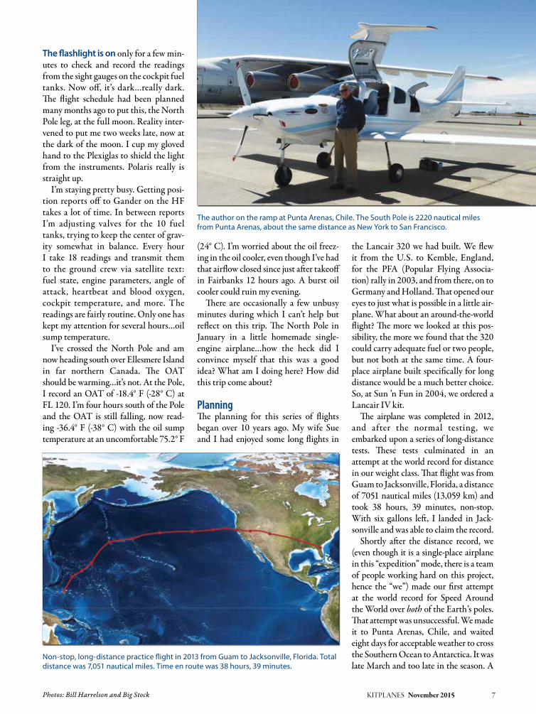
The author on the ramp at Punta Arenas, Chile. The South Pole is 2220 nautical miles from Punta Arenas, about the same distance as New York to San Francisco.
Non-stop, long-distance practice flight in 2013 from Guam to Jacksonville, Florida. Total distance was 7,051 nautical miles. Time en route was 38 hours, 39 minutes.

long flight back to the U.S. ended that first attempt.
An official World Record sanctioned by the Fédération Aéronautique Interna-tionale, keeper of aviation records since 1905, requires following a strict set of requirements. For this particular record, these requirements include: 1. The aircraft must be officially weighed
at the maximum weight that it will be flown at during the record attempt.
2. The flight must fly directly over both the North and South Poles.
3. The northbound and southbound equator crossings must be separated by a minimum of 120 degrees longitude.
4. All declared points must be reached in the order that they were declared.
Speed is computed by dividing the total great circle distance between declared points by the total time. Total time is computed from the first takeoff
to the last landing back at the start-ing point. Flying other than directly between declared points is allowed, but is not counted in the total distance.
The Journey BeginsWe chose Kinston, North Carolina, KISO, as our start/end airport. Kinston has a long 11,500-foot runway (needed at our extreme weight), a tower (needed to attest to takeoff and landing times), and
8 KITPLANES November 2015 www.kitplanes.com & www.facebook.com/kitplanes
The route flown: 31,118 nautical miles, 24 days, 174.9 hours—lots and lots of ocean with some ice here and there.

an excellent FBO (thanks, Kinston Jet Center). Kinston is also geographically situated such that we had a clear route through the warning areas that exist all along the U.S. East Coast.
Since we needed to fuel to maximum for weighing at Kinston, we planned the first leg to be our longest, east to cross the equator at 44 degrees west longitude, and
then south across Brazil to Montevideo, Uruguay, SUAA, a distance of 5286 nau-tical miles and planned for 28 hours. At our max fuel weight, takeoffs are always a challenge. Normal rotation speed for this airplane would be around 65 knots. At max weight rotation is 105 knots, and the wheels leave the ground at 110–115 knots. Once off the ground, climb rate is
100 fpm or less until an airspeed of 160 knots is reached. Then it can maintain perhaps 400 fpm until 8000 feet or so, when it will climb no further until fuel weight is burned off. The aft CG makes the airplane divergently unstable. The Lancair IV, normally a pleasant-to-fly, responsive aircraft, is an ugly, difficult-to-fly, poorly performing pig at this
KITPLANES November 2015 9
Our friend and handler in Montevideo, Gualdemar Gutierrez.
The long scat tubing is a heater hose. All instruments and avionics are on the left side of the panel, and the right side is completely blank. This allows the space between the panel and the firewall to be used for a 13-gallon header tank.

weight and CG. Use of the autopilot is out of the question for the first five or six hours. After this, the CG is such that, in smooth air, the autopilot can be engaged. This is always a major relief. Now more attention can be devoted to weather avoidance, navigation, fuel management, communication with the ground crew, and perhaps a moment or two to eat, drink, exercise, and think.
Landing at the Angel S. Adami air-port, SUAA, in Montevideo was a great pleasure. Adami is a wonderful little general aviation airport with quick and easy customs, self-serve avgas, and best of all, the friendly face of Gualdemar Gutierrez. We had been communicat-ing with Gualdemar for many months prior to our arrival. He had arranged everything: fuel, transportation to the hotel, customs, etc. He had agreed to accept a package that we had sent ahead (clean underwear, PowerBars, oil, Cam-Guard, etc.). Since our next leg would be a relatively short leg to Punta Arenas, Chile, we could afford to carry some supplies from there.
The weather the next morning was acceptable and the short hop (1329 nau-tical miles, 7 hours) to Punta Arenas went quite smoothly. Argentina ATC was competent and friendly as we passed this leg almost entirely over their coun-try. Good weather prevailed for landing in Punta Arenas, Chile.
Good News, Bad NewsAfter clearing customs, the next stop was the met office. I had found on my previous flight to Punta Arenas that the
meteorologists here were first class. They had up-to-date equipment and were extremely knowledgeable, especially concerning Antarctic weather. They had good and bad news for me. The flight from Punta Arenas to the South Pole the next day should be during a rare window of excellent weather and only moderate headwinds. There was, however, bad weather over the Southern Ocean on the way from Antarctica to New Zealand. Since the weather from South America to the Pole looked unusually good, the decision was made to take advantage of the good weather and depart for the Pole the next day.
For years I had known that this leg from South America across the South Pole to New Zealand would be the most critical and dangerous leg of the entire project. The Southern Ocean is infamous for extreme and rapidly
changing weather. Weather reporting stations are few and possible landing sites almost non-existent.
A maximum-weight takeoff with the full 361-gallon fuel load and a very slow climb over the Strait of Magellan toward the mountains of southern Tierra del Fuego started this leg. With excellent visibility, the mountains and glaciers at the southern tip of the continent were soon visible. Monte Sarmiento at 7175 feet was the highest obstacle in my way. I was able to hold 10,000 feet as I passed just to the west of this spectacu-lar mountain. In the words of Charles Darwin, “the most sublime spectacle in Tierra del Fuego.”
Once past Tierra del Fuego, it’s over the Drake Passage toward Antarc-tica. Hours pass with the open ocean mostly obscured by low clouds. Just a few higher cumulus are visible on the
10 KITPLANES November 2015 www.kitplanes.com & www.facebook.com/kitplanes
One of four glaciers at Monte Sarmiento, at the southern tip of Tierra del Fuego.
Departing South America. The tip of the continent is best described as cold, icy, and rocky.

KITPLANES November 2015 11
N6ZQ was constructed from the ground up to be an extreme-range oceanic cruiser. It would be challenging, but certainly not impossible, to convert an already built airplane. What kind of modifications are necessary to produce a plane with these capabilities? The first and most necessary mod is fuel.
There is plenty of room in most airplanes for lots of extra fuel. There is, however, rarely plenty of extra CG envelope. In N6ZQ, as in most planes, the need was to get as much fuel as far forward as possible. The cornerstone of our fuel system is the header tank. We designed the instrument panel to have all instruments and electronics on the left side. The right side of the panel is completely blank. This allowed space between the panel and the firewall for a 13-gallon header.
The engine runs only on header tank fuel. Fuel from all other tanks gravity flows through on-off valves to a manifold at the system low point in the cockpit. From there it is pumped into the header by any one of three electric pumps. Each pump is powered by a different electrical system. There are float switches mounted in the header that operate an automatic pumping system to keep the header at a near-full level at all times. In case I mismanage the valves or fail to have at least one pump operational and no fuel is being pumped into the header, there is a big red flashing light (http://pillarpointelectronics.com/kits.html) that comes on at the 7-gallon level. That would give me about 40 minutes to correct the situation. The header is equipped with a carefully calibrated sight gauge that provides very accurate, non-electrical dependent, header tank fuel quantity indications.
The right side rudder pedals are removable. That allows room for the fuel tanks in what would normally be the copilot footwell to extend from the wingspar to the firewall. We have a total of 58 gallons of fuel in the fuselage forward of the mainspar. The copilot seat area, the back seat, and back-seat footwell are all filled with carbon/fiber-glass fuel tanks. All of the hard tanks are equipped with sight gauges. In addition, two Turtle-Pac (http://www.turtlepac.com/) bladder tanks are positioned on top of the rear-seat tank. The forward Turtle-Pac is filled to capacity, 66 gallons, while the aft Turtle-Pac is restricted to 30 gallons. At max fuel, N6ZQ holds 361 gallons. A removable bulkhead wall is immediately behind the aft Turtle-Pac to ensure that these drum bladders cannot move or expand aft.
The next consideration for long range is electricity. Since this airplane is so electrically dependent, we built three separate and independent electrical systems, three alternators, and three batteries (www.bandc.biz). An essential bus is powered through large Schottky diodes by all three electrical systems. The avionics bus is likewise powered by systems #1
and #2. The primary GPS/COM, a Garmin 480, which is normally powered from the avionics bus, can also be powered through a switch from system #3. The three main power buses can be cross-connected in any combina-tion. The engine can be started with one, two, or all three batteries. Normal start is with batts #1 and #2. We felt that these multiple layers of redundancy were warranted considering the airplane’s mission.
Another piece of equipment that is necessary for oceanic flight is an HF (High Frequency) radio. Our system consists of an Icom 706 Mk II G ham radio modified to transmit on aviation HF frequencies. The HF consists of four components. The control head is small, light, and is attached to the copilot seat fuel tank with Velcro. The radio itself is mounted in the maingear well, and the antenna tuner unit (Icom AH-4) is mounted in the lower aft fuselage. The antenna consists of a fixed 40-foot length of bronze wire with a small weighted funnel attached to the end as a drogue. The antenna trails behind the airplane and is not retractable. Since the antenna drags on the ground during taxi, takeoff and landing, it sees a bit of wear and needs to be replaced every 10-12 landings. It is easily (two minutes) removable when HF is not required.
N6ZQ is equipped with a satellite communication system. During construction, a permanent Iridium satellite antenna was built into the vertical stabilizer. An Iridium GO unit (www.iridium.com/iridiumgo.aspx) allows text, voice, and limited email capability. Voice operates via Bluetooth to the headphone (www.akg.com/pro/headphones/ akg-aviation). Texting, email, and voice are accomplished via a Wi-Fi link between the Iridium GO, an iPhone, and iPad. We found that text was, by far, the preferable means of communication with the ground crew.
Of course, none of this equipment is any good without a depend-able, efficient engine. Ours is a Continental IO-550 that was overhauled and modified by Barrett Precision Engines (www.bpaengines.com). Barrett equipped the engine with 10:1 pistons for greater efficiency. The engine now has over 800 hours, and we’ve never had to add a quart of oil between oil changes. We have used CamGuard oil additive (http://aslcamguard.com) since engine break-in. The engine has run flawlessly since day one.
While the header tank and the three electrical systems are an integral part of the airplane, the “expedition configuration” tanks and equipment are removable. It’s about two days’ work to convert this airplane back to a four-place Lancair IV. The back-seat tank and back-seat footwell tank can be left in to make an extended-range two-place configuration. In the two-place configuration, Sue and I can make short hops such as Europe or Hawaii.
—B.H.
Building a Long-Distance Cruiser
Forward fuel tank in the copilot seat area. Neighbors helped close up the wings. Five of the 10 total fuel tanks.

southeastern horiz…wait a minute…those aren’t clouds. They’re the moun-tains of the Antarctic Peninsula! The first view of this magic continent while still 200 miles away is something that I’ll never forget. The view gets more spectacular the closer I get. My route takes me over Mount Stephenson on Alexander Island. This is the fourth highest peak in Antarctica and probably the most visually impressive since it rises directly from the sea in one unbroken 60-degree slope of rock to 9800 feet.
I continue following the 71-degree west meridian toward the Pole. Passing over the peninsula and then over the western edge of the Ronne Ice Shelf, I find myself in stratus clouds. The tem-perature is well below -4° F (-20° C) and I encounter no ice. Once out of the stratus, I can see the Sentinel Range far to the west and Vinson Massif, the
highest point in Antarctica at 16,067 feet, impressive even from a distance.
AntarcticaThe interior of the Antarctic continent is surprisingly featureless. Hundreds of miles pass and it looks as if I’m flying over a smooth cloud layer. Only occa-sional crevasses and rock outcroppings show that it’s snow and ice. The GPS units are now showing a maddeningly decreasing groundspeed. The headwinds are stronger than forecast—consider-ably stronger. By the time I reach 85 degrees south latitude, I’m 1 hour and 1 minute behind flight plan and worse, below flight plan fuel. This leg is a 5383-nautical-mile flight into increas-ing headwinds, questionable weather, a high probability of icing on the second crossing of the Southern Ocean, and no place to land, short of New Zealand.
It’s decision time. The ground crew and I reach the frustrating conclusion that to continue past the Pole toward New Zealand would put the flight into a far too risky and uncertain situation. We decide to continue to the Pole and then return to Punta Arenas. It’s 2220 nautical miles from Punta Arenas to the Pole, the distance from New York to San Francisco…and another 2220 miles back, but still shorter than continuing to New Zealand. I work out a flight plan for the return and advise ATC on HF of our decision.
Finally, over the nose, I see Amundsen-Scott Station, the U.S. research base at the South Pole. It looks like a junkyard at the end of the earth. A few circles around the Pole, snap a few photos and I’m on my way north back to Punta Arenas.
Airframe IcingAntarctica is known for rapidly chang-ing weather. It did not disappoint. Even over the same areas that I had flown over just a few hours ago, I notice more clouds. Over the continent I’m not worried about airframe icing since the temperature is well below -4° F (-20° C). Over the Southern Ocean, however, just 100 miles short of South America, with warming temperature and increas-ing cloud cover, I encounter ice. Just a little at first, but on the thin Lancair air-foils, it’s enough to appreciably degrade performance. It soon becomes obvious that I cannot remain in this situation for long. I’ve been descending to remain below the clouds. I’m at FL 140 now. I check the OAT and calculate how low I
12 KITPLANES November 2015 www.kitplanes.com & www.facebook.com/kitplanes
Amundsen-Scott station looks like a junkyard at the South Pole.The spectacular mountains of Antarctica.
Bad news from Tahiti: They rejected the author’s flight plan. It seems they require 72 hours to issue a landing permit.

need to descend to find above-freezing temperatures—6000 feet should do it—but it doesn’t. At 5000 feet the ice finally starts melting…slowly. But now, I’m getting close to Tierra del Fuego and the mountains there. I need to get back up to at least 10,000 to clear the rocks. Luckily, as I continue north, the temperature continues to increase and I’m able to climb back to a safe altitude free of ice.
Back in Punta Arenas I now have a new set of challenges to face. I need to do the oil change that had been planned for New Zealand. Julio Sopik, my friend and handler in Chile, is able to find a case of oil. We do an oil change on the cold ramp in a 40-knot wind which is pretty normal weather in this part of the world.
I have made it to the Pole so as far as the official record is concerned—I do not need to return there. Since Hamil-ton, New Zealand, has been declared, I still have to get there somehow. The most direct route will take me well back into the Southern Ocean into 50- to 60-knot headwinds and, very likely, icing. Although we keep looking at this option, we explore what other possibili-ties are available.
Easter Island would be a great stop, if only they had avgas. They don’t. We could arrive at Easter Island with some tanks still full of avgas. Would car gas be a possibility? We could take off and climb on avgas and then at low power cruise start burning the car gas. Con-sultations are made with engine experts back in the States, and it is determined that this would probably work…proba-bly…not a comforting thought when fly-ing thousands of miles over open ocean.
How about Raratonga? Pretty far, but might be possible. Tahiti could work. We search for avgas there and find none. Then, Ewan Smith from Air Raratonga contacts the team and finds three bar-rels of avgas in Tahiti. Super! We file the flight plan for Tahiti. But just before departure a message arrives that Tahiti has refused our flight plan. Seems that they require 72 hours to issue a landing permit…no exceptions.
To be continued… J
KITPLANES November 2015 13

www.kitplanes.com & www.facebook.com/kitplanes14 KITPLANES November 2015
Lady Bug’s Story

Photos: John Fleck and Paul Berg • Air-to-air photo: Tyson V. Rininger
Building a fastback RV-8 and winning a Silver Lindy.By Paul Berg
My story begins over thirty years ago. It began after a flight lesson when my instructor asked, “Do you know Walter Gee? He’s building a Long-EZ. You should check out his project.”
As fate would have it, we were destined to meet. I remem-ber the first time I met Walter, walking in his shop, seeing a fuselage resting on sawhorses, the smell of epoxy, Long-EZ drawings hanging on the shop wall, and pictures of the dream he was building. For two years I watched epoxy and cloth being transformed into his wonderful flying machine. From my front row perch, I was inspired by Walter’s crafts-manship, dedication, and the way he handled the scratch-your-head moments when things weren’t going well. I don’t know when the seed was sown for me to follow Walter’s dream, but from the moment I watched his beautiful Long-EZ rotate on its maiden flight, I knew building an airplane would be in my future.
I was born with the incurable disease called aviation; a dis-ease most aviators can relate to. Sometimes we have to put our dreams on the shelf for a season and this happened to me. Our farming businesses and growing family didn’t afford
time or money for building a plane. Looking back, I realize how valuable this period was to the success of my future proj-ect. My free time was spent researching kit options that would meet the mission requirements important to me. The first requirement was a plane capable of operating safely from our grass strip, which narrowed my choices. In 1999 I was invited to a fly-in surprise birthday party at a local airport. On the ramp was the most beautiful yellow Harmon Rocket, and for me, it was love at first sight. For the next five years, my plane of choice was the Harmon Rocket.
Rocket or RV-8?I started spending time researching Van’s “Total Perfor-mance” Aircraft. I wanted a kit manufacturer with good product support, standardized parts, and a history for lon-gevity. The RV-4 was the only option for a two-place tandem-seat and tilt canopy kit. It’s a nice plane that would meet the grass strip requirement, but far from the lines of the Rocket. I need room for my 6-foot-1, 190-pound frame; the RV-4 cock-pit would be tight for me. The RV-8, with its wider fuselage,
KITPLANES November 2015 15

was my next option, but I just couldn’t get the picture of the yellow Harmon Rocket out of my mind.
As I walked thru the lines of RVs at AirVenture 2006, I mistook an RV-8 for a Harmon Rocket. The builder had modified his RV-8 with Show Planes’ fastback tilt canopy and engine cowl conversions. Show Planes engine cowl is longer than the stock RV-8, requiring a two-inch prop extension when a four-cylinder engine is used. The spinner hub diameter is 15 inches, and the length of the spinner is 21 inches. The longer cowl, in combination with the fastback, had dramatically changed the RV-8 look! This conversion affords unrestricted pilot visibility, improves cockpit entry, especially to the rear seat, seals better than a sliding canopy, and affords full access to the aft side of the panel with a removable instrument cover. Weigh-ing the advantages of building an RV-8 with Show Planes’ conversions and hav-ing Van’s kit support made lots of sense, and my final decision was made: I would build an RV-8.
Following a DreamThe summer of 2008 was perfect for growing grass in central Indiana. One day, after mowing the runway for the second time that week, I told my wife, “Something has to change! I’m not interested in maintaining the airstrip any longer.”
We had sold our Cessna 182 and a beautiful J3 Cub, and the hanger was being used for equipment storage. My dream of building a plane seemed very distant. I was running out of time, and I wasn’t interested in a fifteen-year build-ing project. My decision to retire from our business was made before attend-ing AirVenture 2008. My sons would assume my responsibilities in our nurs-ery business, and I would devote full time to building. I’ll be honest—I ques-tioned the sanity of my decision on more than one occasion. Today my finished RV-8 represents the aviation journey of my life with thousands of build hours and decisions, good and bad, made along the way. This was a full-commitment decision, and it was time to get started.
I can’t remember a time in my life when I wasn’t building or fabricating something. I’d been researching this project for years, attending forums and workshops, but still didn’t feel prepared for building a plane. One evening I was searching for the nearest tech counselor in our area when I discovered a builder’s assistance course offered ten miles from my home. I felt like I’d struck gold. My wife and I signed up for the weekend course and learned the basic skills used for building a plane. For a nominal fee, to cover tools and shop overhead, I could rent shop space for building my empen-nage, an offer I couldn’t turn down. The next three months were spent learn-ing building techniques from an A&P mechanic experienced in the construc-tion of RV series aircraft. When my empennage was finished, I felt prepared to work on my own and moved the proj-ect to my shop at home.
At last my dream of building a plane had become a reality. I’d gained confi-dence building my empennage, but I still felt like a mistake waiting to happen.
16 KITPLANES November 2015 www.kitplanes.com & www.facebook.com/kitplanes
The cockpit side of the firewall has a ceramic blanket (left) that is covered in foil (Center). The engine side of the firewall is insulated with a 1/8-inch Fiberfrax blanket (right) that will withstand temperatures up to 2300° F. The blanket is covered with a stainless steel skin.

Oddly, this feeling would be my compan-ion, with its watchful eye on everything I did, constantly warning me to measure again and check the drawings one more time. Early in the project I implemented a system for combating this fear. When practical I’d mock up what I was about to do on the bench with scrap material or fabricate a template to get it just right. One of my most prized possessions is a box containing the templates used to build my plane.
A Contender?I don’t recall when I first thought I might build a plane capable of compet-ing for an Oshkosh Lindy, certainly not at the outset of the project, but the idea was in the back of my mind. When I walked through the rows of kitbuilt planes at AirVenture, I’d look for ideas
and pay close attention to fiberglass fit, finish, and metal work. I felt a Lancair would be competitive. For an RV to compete with the perfection, sportiness, and factory in-house assistance Lancair provides builders, there would be little room for error.
I was enjoying the freedom granted to builders who build Experimental air-craft. My standard kit from Van’s was the new one and perfect in every respect—so perfect I often thought I was cheating when I’d think what builders before me endured building their planes. The Har-mon Rocket was my model, and I was free to make modifications to the kit with no STCs, no field approvals, and no red tape.
The major modification needed to achieve this goal would be conversion of the fuselage to a fastback, installation
of the tilt-over canopy and instrument cover, and Show Planes engine cowl conversion. I was making good progress building the fuselage, following the step-by-step instructions. That all changed when I started laying out my firewall, a complete deviation from the layout sug-gested in the plans.
When I started building my fuselage, a friend suggested I make templates for the cockpit side of the firewall. “It will be easier to do on the bench than when it’s assembled. You’re going to need them when you soundproof the firewall,” he said.
I followed his advice, made the tem-plates, and put them on the shelf. I ordered the adhesive-backed sound-proofing he recommended, but when UPS delivered the box, I knew I’d made a mistake. On the Van’s Air Force web
KITPLANES November 2015 17
It’s the little things builders do that create a common bond between man and machine. The author didn’t like the way the flap actuator is exposed in the back seat of an RV-8, so he added a cover. The cover was then upholstered to match the custom leather seats.
The roll bar is part of the Show Planes conversion. In addition to providing rollover protection, it makes cockpit entry easy, especially to the rear seat. For easier maintenance, the removable instrument cover gives full access to the aft side of the panel.

site, I found information posted by KITPLANES® contributor Dan Hor-ton. He was doing burn tests on differ-ent materials used on firewalls. I knew the adhesive-backed soundproofing I had was heavy. What I didn’t know was the adhesive glue would emit deadly gas in a fire!
A firewall modification would require additional time. It would be the most important safety upgrade I would add to my plane and the most challenging. When the modification was finished, the engine side of the firewall was insu-lated with a 1/8-inch Fiberfrax blan-ket that will withstand 2300° F and is covered with a stainless steel skin. The firewall pass-throughs with firesleeve, dual heat valves, and fastening hardware are also stainless steel. The cockpit side of the firewall has a ceramic blanket cov-ered in foil with 0.020-gauge aluminum panels to protect the foil and improve appearance. I used no adhesives. An engine over-temp sensor mounted on the firewall above the cold air ramp ener-gizes a warning light on the instrument panel if temperatures exceed 220° F. My weight penalty is 8.9 pounds; the sound-proofing material I was going to use would have weighed the same, perhaps more. Worst of all, it could have been a lethal hazard in an engine fire.
The Joy of BuildingWhat’s it like building a plane? For me it’s like falling in love with a wonderful
girl. It sounds strange, but I never grew tired of building nor did I ever reach the point of burnout. When I was away from the project, I really wasn’t; if you’re a builder you know the feeling. My thoughts continually operated in the background in search of ideas. As my fuselage took form, it became more than bulkheads, longerons, and skins riveted together—it became an exten-sion of me.
Modifications personalized my plane and were a joy to do. When Aerotron-ics, my avionics supplier said, “Paul, we need two more inches to get everything on the panel,” a panel modification was done and a panel template fabricated and sent to Aerotronics.
A friend, flying beside and below his dad’s RV-8, noticed the bottom skin
oil-canning; upon inspection work-ing rivets were found. With this infor-mation, I did a modification adding stiffeners to the belly skin of the tail section and added a doubler aft of the gear legs. The tail stiffeners are riveted to doublers attached at each bulkhead and to the skin.
I’ve never liked the way the f lap actuator is exposed in the back seat of an RV-8, so mine received a cover. It’s the little things builders do that cre-ate a common bond between man and machine, that make the result an exten-sion of the builder.
Very early in the project I reserved my N-number, N938W, a number with meaning. I started building September 3, 2008. The international alphabet code for W seemed a good way to figura-tively re-christen my plane each time her number is mentioned.
I also started working early, with Scheme Designers, to develop a paint scheme for my plane. When a scheme was rendered, I hung it on my shop wall. I was reminded, with each ren-dition, that my eldest sister was the recipient of all the artsy genes in our family. Unexpectedly, this phase led to the most challenging, aggravating, and in the end, rewarding event in the project. Paint schemes aren’t high on the list for earning points when an aircraft is being judged; the majority
18 KITPLANES November 2015 www.kitplanes.com & www.facebook.com/kitplanes
The well-equipped panel includes a Garmin GNS 430 navigator, GDU 370 PFD, GDU 375 MFD, GTX 327 transponder, GMA audio panel, TruTrak GX autopilot, and Dynon D10A EFIS.
The Show Planes conversion includes a tip-over canopy to replace the standard RV-8 slider.

KITPLANES November 2015 19
Painted LadyWithout a doubt painting the plane was the biggest challenge of the project. The scheme has black checks faded into yellow. For this reason professional paint shops were reluctant to price the job, so the decision was made to do it ourselves. We bought a very used paint booth, reassembled it in our farm shop, and started preparing the plane to receive its wardrobe.
First, the fuselage was prepped and primed gray, followed by a white base coat, which must be used before painting yellow. Next, the fuselage was sanded and masked for red, and then the faded checks were sprayed.
We practiced painting the fade on numerous test panels. Nevertheless, we failed on our first attempts to paint the wings and fuselage. Finally, we cracked the code that had eluded us. Drop shadows and pinstripes were added to the scheme for extra flair.
—P.B.
Priming the fuselage. Yellow is applied over a white base coat. After masking, the fuselage is sprayed red.
The left wing painted yellow and red. Masking the wing for the checks. Blue tape marks indicate fade transitions.
Faded checks applied to the fuselage. The left wing after spraying the checks. Pinstripes are painted with a small brush.

are done in professional shops, and they shouldn’t count. What if we painted the plane ourselves? Common sense told me it had to count for something.
First Flight The droning of an approaching engine resonated through the morning air, reaching a crescendo as it entered the pattern to land on my grass strip. Weather the morning of April 18, 2014, couldn’t have been more suit-able. Light and variable winds favor-ing our north-south grass strip are rare in central Indiana. The sun glis-tened as Jon Hubbell taxied his RV-6 to the hanger. The early morning dew reflected from his wheelpants as he shut his engine down. Through the open hangar door sat the steed Jon would be piloting on its maiden flight, the open canopy beckoning for some-one to “take me flying.”
I had long abandoned the thought of piloting the first f light. Six years with over 7000 hours of building time didn’t allow for maintaining
stick-and-rudder proficiency. Most importantly, I was emotionally invested in the plane. A pilot builder lacking pro-ficiency and being emotionally involved is a dangerous combination, a chance I was not willing to take.
Jon is an accomplished builder, an A&P mechanic, and pilot with first-flight experience. A more perfect mar-riage of man and machine would’ve been impossible to find. I watched as Jon climbed into the cockpit, secured
his harnesses, locked the canopy in its taxi position, and started running through the checklist.
“Clear!” Three blades and the engine came to life. The sound of the Vet-terman four-pipe exhaust system was music to my ears! As Jon taxied to the runway, I was overwhelmed by a ner-vous feeling; my friend was minutes away from flying the plane I’d built. I watched the takeoff roll. It seemed to be in slow motion. Her tail rose, the
20 KITPLANES November 2015 www.kitplanes.com & www.facebook.com/kitplanes
It’s Showtime!Our AirVenture display took months to create. We filled four binders with building logs and pictures, detailing every aspect of building the plane. Another binder had the electrical wiring schematics profes-sionally done by a friend, and the engine and airframe logs were also available. To add some flair we wore shirts with the same paint scheme as Lady Bug.
On the first day of the show a gentleman asked, “Do you mind if I take detailed pictures of your plane?” I said, “Not a problem. If you need the canopy or anything else opened I’ll be happy to do it.” He became a regular visitor. Toward the end of the show, I saw him
walking toward my plane. Approaching me he said, “I can’t leave without thanking you for bringing your plane to Oshkosh.” Lots of similar stories could be told. The show of appreciation will always be a highpoint of our Oshkosh experience. My first ride came when we flew with EAA on a photo shoot. When we landed, arrangements had been made for a quick picture with the Air Force Thunderbirds in the background. I was honored when General Dan Cherry, a former Thunderbird commander, posed for a picture. But the icing on the cake was having Richard VanGrunsven visit our plane. J
—P.B.
Four albums detailed every aspect of building the plane.
Aero Sport Power IO-375 engine with Vetterman exhaust and Whirl Wind 200RV prop.
Richard VanGrunsven and Paul and Peggy Berg.

Six years and over 7000 hours of building time didn’t allow the author to maintain
pilot proficiency, so Jon Hubbell made the first flight from the author’s grass strip.
mains rotated, then after briefly flying in ground effect, Jon quickly climbed to a safe altitude circling the runway. The morning sun beamed off the wings as they banked into the turns with the blue sky silhouetted in the background. I can’t describe the feelings that over-whelmed me.
After thirty minutes of nervous bliss, N938W lined up on final, completing its first flight with a textbook three-point landing. Jon taxied to the hanger, shut down the engine, and opened the canopy with a huge grin on his face.
“Paul, does your plane have a name? Planes need a name. As I was flying, I looked out at the wing and a ladybug was clinging to it; I think you should name it Lady Bug.”
Jon knows Lady Bug well, f lying 12 hours in one day to finish the Phase 1 requirements, just days before leav-ing for Oshkosh. Without Jon’s help, there wouldn’t be an AirVenture story to tell.
AirVenture The most amazing week of our lives was spent showing our plane at AirVenture 2014. Days started with a stop at Sacred Heart’s concession stand by the main entrance for coffee and a sweet roll, then we’d walk to our plane tied down north of the north taxiway. My wife and I made a commitment to our plane, judges, and attendees to stay with the plane during the show. Porta Jon breaks were the only exception.
Monday, July 28, 2014, was the first day of judging. Lady Bug glistened in the sun, secured with its tiedowns, decked in show array. Months had been spent pre-paring for this day; I’d documented the journey with build logs and a series of four albums telling Lady Bug’s story. Displayed between the gear legs was a banner with Lady Bug’s first flight captured on its cen-ter. By week’s end a brown grass trail cir-cled Lady Bug. A dream conceived thirty years earlier as I watched Walters’s first flight had come true for me, and it was an incredible journey! The most awesome gift I received from my Oshkosh experi-ence was meeting and sharing my passion for flight with fellow builders and those catching the dream. N938W was the AirVenture 2014 Silver Lindy recipient. J
KITPLANES November 2015 21
The author’s first ride—Jon Hubbell front seat, Paul Berg rear. Lady Bug with the Air Force Thunderbirds at AirVenture 2014.

www.kitplanes.com & www.facebook.com/kitplanes22 KITPLANES November 2015
had yet to craft many rules relating to amateur-built jets, mainly because there weren’t any. The Turbomeca burned something like 100 gallons per hour of Jet-A, not exactly efficient but tolerable. Unfortunately, by the time Rusty was flying, everything had changed.
Jet-A is now over $4.00 per gallon, and that is down from its peak. The Tur-bomeca engine didn’t produce enough thrust, so it got replaced with a power-ful but thirsty General Electric CJ610 engine out of a Learjet 23. The FAA now requires the equivalent of a type rating to fly the Viperjet, and that must
380 knots the hard way.By Dave Prizio
Back in 1999, Rusty Skinner had the itch to build an airplane. He was looking for a high-performance craft with some real speed. When he saw the prototype of the Viperjet under construction by the Hanchette brothers in Pascoe, Washing-ton, he was sold. The prototype had not yet flown, but Rusty knew that he had found his next project. The Hanchettes had begun work on a piston-powered pusher but decided even before flying that a pure jet was going to be the way to go. They planned to replace the big Lycoming with a Turbomeca Marboré II such as the ones found in the French Fouga Magister.
This engine would have made the Viper-jet reasonably affordable to build and fly.
Without so much as a flying prototype to prove performance, Rusty put down his money, which financed the first set of proper molds for the new Viperjet. The dream was to get a fast, economical homebuilt jet that would be easy to fly and reasonable to operate. There was more work to be done and more slippage of the dream than anyone expected, but today Rusty is flying his very own Viperjet.
At the time this didn’t seem like such a wild thing to hope for. Jet fuel was sell-ing for under $1.00 per gallon. The FAA
Viperjet
Viperjet N999VJ is right at home at Chino Airport in Southern
California, where L-39s and F-86s are a common sight. Unfortu-
nately they all share a common trait of devouring huge amounts
of Jet-A on every flight.
AIRPLANE EVALUATION
Photos: Dave Prizio, Rusty Skinner KITPLANES November 2015 23
be renewed yearly. The one-page main-tenance program that the Hanchettes managed to get approved when the first prototype flew grew to 66 pages and had to be created with no factory support. And the once attainable service ceiling of 45,000 feet has been trimmed down to 28,000 feet by Reduced Vertical Sepa-ration Minimum (RVSM) rules.
No Plans or InstructionsThe biggest problem Rusty faced, again and again, was that the Hanchette brothers were just barely ahead of their builders in figuring things out as they went. There were no plans or instruc-tions for the Viperjet. Trips to the fac-tory to photograph and measure the prototype took the place of the missing plans. And when parts were not forth-coming, Rusty had to make his own. The engine choice went through three iterations before one stuck. A General Electric T58 helicopter engine was tried after the Turbomeca engine, but it too was rejected because it was underpow-ered. With the CJ610 the plane now performs like a real fighter, but runs out of fuel before you can fly anywhere.
All of this could have discouraged lesser men, but Rusty never gave up. He loves the building process, and he loves meeting a challenge, figuring things out, and blazing a trail for others to fol-low. He had exactly the right tempera-ment to take on this project. As a result
he has one of the few completed Viper-jets in existence.
Rusty began his project with the inte-rior and the instrument panel, since the engine selection process was making it difficult to do anything in that regard. The kit came with an empty fuselage when he started, so every interior item had to be designed and molded out of fiberglass from scratch. Later kits had more of these parts prefabricated by the factory, but one of the perils of going first is not having things worked out ahead of you.
Rusty wired the panel himself with a little help from Western Avionics out of Orange County (John Wayne) Air-port. His panel is state of the art from 15 years ago. It still looks impressive, but no one would build a panel like
that today, and some of the items are no longer even serviced by their man-ufacturer anymore. Extended build times cause such problems as this for many builders in this age of rapidly evolving avionics.
As Rusty proceeded through the build process toward completion, two key people emerged to help smooth the way. Cliff Tabor was a long-time jet mechanic who had cut his teeth on the old Learjets. He knew the CJ610 engine inside and out. His assistance and tute-lage made it possible for Rusty to get the engine installed and running as well as it
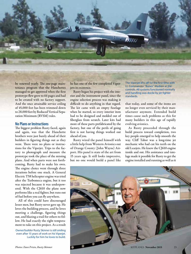
Owner/builder Rusty Skinner is still smiling even after 15 years of work on his Viperjet.
Luckily for him he loves to build.
The Viperjet lifts off for the first time with Lt. Commander “Bones” Medore at the controls. All systems functioned normally and handling was docile by jet fighter standards.

does. This was a great benefit because jet knowledge is hard to find in the Experi-mental/Amateur-Built world. Lots of people know about Lycoming piston engines, but hardly anyone has ever built a homebuilt jet before.
The other great find was Lt. Com-mander Doug “Bones” Medore. He is a real live Navy fighter pilot who had finished out his service as a Top Gun instructor. Who better than he to fly the Viperjet and train Rusty to pilot his own fighter jet? On May 30, 2013 Bones took off from Chino Airport to become the pilot of the first customer-built Viperjet. He describes the plane
as easy to fly and very forgiving—for a fighter jet, that is.
At this point Rusty is getting his share of stick time in his new jet, but the requirement of a type rating flown to ATP standards and renewed every year is daunting for a pilot with lots of much less precise flying in his logbook. For the time being Bones will be flying with Rusty on their many short trips. Their hope is to make a flight to Phoenix sometime in the near future, but the fuel situation makes that a real challenge. What they need is another tank to get access to another 100 gallons or so of fuel. The Viperjet Mark II has this extra fuel capacity, but Rusty is unsure of just how to fit that much fuel in his plane.
Maybe he could fashion himself some drop tanks.
Imperfect PitchOne thing Rusty has noticed while flying the Viperjet is the need for very precise pitch control. At 300 knots even the slightest pitch change can cause a large change in altitude in a big hurry. This is not news to people who fly such planes, but for those of us who spend our lives flying at half that speed or less, it is a real eye-opener. Fortunately the Viperjet has a fairly reasonable stall speed of 77 knots in the landing configuration, so coming over the fence at 100 knots and touch-ing down at 95 knots makes for land-ings that are similar to those of many light twins.
Once the plane was flying, new prob-lems emerged. A weld on the nosegear strut failed on landing, damaging the composite structure as the nose slid down the runway with no wheel under it. The repair wasn’t too difficult, but it did take the plane out of commission for several weeks during the flight test period. More recently the computer that controls the flaps and landing gear failed. Luckily there was no dam-age as a result, but Rusty had to replace the computer with a system of more
24 KITPLANES November 2015 www.kitplanes.com & www.facebook.com/kitplanes
An extended building process and the rapid changes in avionics have left Rusty with a beautiful, but now obsolete, panel. It is, however, very functional, so Rusty doesn’t mind.
A still rough-looking but steadily progress-ing BD-5J is coming together alongside the now-complete Viperjet. It should be a real crowd pleaser when it is finished.
Viperjet SpecificationSSeating Capacity . . . . . . . . . . . . . . . . . . . . . . . . . . . . . . . . . . . 2Length . . . . . . . . . . . . . . . . . . . . . . . . . . . . . . . . . . . . . 25 ft 6 in Wingspan . . . . . . . . . . . . . . . . . . . . . . . . . . . . . . . . .27 ft 10 inEmpty weight. . . . . . . . . . . . . . . . . . . . . . . . . . . . . . . . 3014 lbGross weight. . . . . . . . . . . . . . . . . . . . . . . . . . . . . . . . . 5500 lbPowerplant . . . . General Electric CJ610-6, 2850 lb thrustFuel Capacity . . . . . . . . . . . . . . . . . . . . . . . . . . . . . . . . 210 gal
peRfoRManceMaximum speed . . . . . . . . . . . . . . . . . . . . . . . . . . . . . . 380 ktCruise speed . . . . . . . . . . . . . . . . . . . . . . . . . . . . . . . . . . 340 ktStall speed (clean) . . . . . . . . . . . . . . . . . . . . . . . . . . . . . . 88 ktStall speed (landing configuration) . . . . . . . . . . . . . . 77 kt Service ceiling . . . . .28,000 feet (Limited by RVSM rules)Rate of climb. . . . . . . . . . . . . . . . . . . . . . . . . . . . . 12,000 fpmFuel consumption (full power). . . . . . . . . . . . . . .200+ gphFuel consumption (idle). . . . . . . . . . . . . . . . . . . . . . . .75 gph
Specifications are manufacturer’s estimates and are based on the configuration of the demonstrator aircraft.

conventional relays that will hopefully prove more reliable.
Two other things have made the whole process more difficult. One, Viperjet is no longer in business, and two, since so many other builders hired professional help, there has never been an online builder forum such as we find with other more popular kits. When you are the first builder, there is no real way to know how these things will turn out; but for most builders, the lack of support from other builders is in itself
a good reason to look elsewhere for a project. It is hard to describe how much help builders have received from forums such as Van’s Air Force, RANS Clan, or GlaStarNet.
The Big Question If you had this to do all over again, knowing what you know now, would you do it?
Rusty’s answer is probably not. He loved the building, in spite of its many challenges, but the end result is just not what he was looking for when he started.
The engine problem caused two very negative outcomes: fuel cost is too high, running something like $800 per hour, and the range is too limited. Lastly, the need for a type rating, which was not the case when he began, has made flying the Viperjet solo much more difficult than he ever imagined.
Rusty says, “If you plan to take on a project like this, you had better like building.” Fifteen years is a long time to spend constructing and refining an airplane project. This is only for people who can work with minimal help and who love the building process, which is certainly not everyone.
So what are Rusty’s plans for the future now that his personal fighter jet is a reality? He is looking at installing some spoilers to help manage steeper descents. These are an option on the Viperjet Mark II, so the engineering is already done. The Mark II was devel-oped while Rusty was building his plane and includes such items as the spoilers, cabin pressurization, added fuel, and other refinements. None of these planes is flying yet, so those refinements are only potential benefits—if these planes ever make it to completion. In the mean-time Rusty is flying, albeit not exactly in the manner he had hoped for.
Lest anyone think that Rusty’s appe-tite for jet-powered challenges has been satisfied, a quick look through his hangar reveals a BD-5J under construction with that leftover T58 engine stuck behind what will need to be a very brave pilot. None other than Bones, Mr. Top Gun himself, plans to pilot the BD-5J at airshows. The 900 pounds of thrust produced by the T58 engine should make for some pretty spectacular vertical penetration, but the plane’s limited fuel capacity will keep the show short. There is no promised comple-tion date for the BD-5J, but there seems little doubt that Rusty will finish it. He is not one who ever gives up. J
KITPLANES November 2015 25
Strakes add yaw stability and were part of the original design.
The weight and landing speed of the Viperjet requires some serious brakes, especially since it does not have any thrust reversers.
FLY ITlike you stole it...
...and leave your enginemonitoring to EIS.
Trusted with everything from 2-strokesto turbines for over two decades.
Proud sponsor of Tiger Airshows and airplane “thief” extraordinaire, Hotwire Harry!
www.grtavionics.com • (616) 245-7700

www.kitplanes.com & www.facebook.com/kitplanes26 KITPLANES November 2015
5:00 p.m.—I get home, but find that Rion has borrowed my little John Deere lawn tractor and is trundling back and forth, back and forth, across his back-yard/taxiway/office lawn.
6:30 p.m.—Rion finally finishes mowing, and that’s when I realize his trailer is now full of the remains of a deck his wife insisted he tear off the back of their house last Saturday. Well, we have to empty the trailer because my truck has a canopy that won’t let the overhead hoist lower the engine into the bed. So we hook up the trailer and head off to the dump.
7:00 p.m.—We unload 1050 pounds of nail-studded rotten lumber from the trailer, stick by stick. On the way home, we realize that we don’t have a good
Working on the wings.By Ken Scott
If your memory and subscription go back a year or so, you might remember the first episode of the Pudding River Bearhawk saga. (Just to refresh your memory, three Oregon neighbors, Phil-lip Groelz, Rion Bourgeois, and I, with occasional help from Rion’s son Elliot, combined our tools and energies to begin building a Bearhawk LSA. It’s a two-seat tandem design by Bob Barrows. It uses an all-metal strut-braced high wing and a steel tube fuselage and tail.)
Once we finished making parts for the wings and were ready to begin assembling them, we needed a really large table—and lo, the minute we needed it, neighbor Mary said that we could have the one in her hangar if we’d take it apart and take it away. Phillip and Rion disassembled the
table, and we hauled it down the strip to Phillip’s hangar where the wing was to be assembled. We immediately found that the big crate containing our engine was taking up all kinds of space where the table needed to go.
We decided to move the engine, still in its crate, three doors down the strip to Rion’s place, known as the Taj Mahangar. It would be easy—Phillip’s shop has an overhead hoist, so we’d get my truck and Rion’s trailer hooked up, lift the engine, slide the trailer under it and move it three doors down to Rion’s. I’d get home at 5:00 p.m., we’d move the engine and have plenty of evening left to get some work done on the wing.
What followed would have made Dick Starks proud…
Building the Bearhawk LSA

Photos: Ken Scott KITPLANES November 2015 27
way to get the engine off the trailer. For that we need my engine hoist, which is at Steve’s, up at the north end of the air-strip. Steve isn’t home, but Phillip has a key to his shop, so we pulled up at Phil-lip’s at 7:30.
Phillip finds the key, but there’s only room for two in the cab of my pickup, so Phillip follows us down to Steve’s on his bicycle. We maneuver the engine hoist around Steve’s RV-3, past his RV-4, out the door and manhandle it into the trailer. The hoist, of course, has to be at Rion’s before the engine arrives, so we drive down there (Phillip pedaling along behind), manhandle the hoist out of the trailer, gently, to avoid scratching Rion’s precious painted floor, drive back up to Phillip’s (Phillip pedaling along behind), hoist the engine, manhandle the trailer underneath it, lower it, and manhandle the trailer back to the truck.
8:45 p.m.—Drive back down to Rion’s (Phillip pedaling along behind), manhandle the trailer back into the hangar, hook the engine to the hoist, raise it, screw special rubber non-mar-ring, floor-protecting casters to the bot-tom of the engine crate, lower it onto the floor, then manhandle the hoist back into the trailer.
9:30 p.m.—Drive back to Steve’s (Phillip pedaling along behind), maneu-ver the hoist back past the RVs, close the hangar, drive back to Phillip’s to drop off the caster-attaching tools (Phillip pedal-ing along behind).
9:45 p.m.—Rion walks home from Phillip’s, so Phillip hops into the truck, bringing with him three beers that have somehow escaped previous notice, and we drive down to Rion’s, detach the trailer and park it.
10:00 p.m.—Open beers, sit down in Rion’s man-cave (attached to the Taj Mahangar). Rion regales us with (com-pletely fictional) tales of his recent feral pig-hunting trip to Sawth K’lina.
10:30 p.m.—We declare airplane building finished for the day and head home. Not one single thing had gotten done on the wing.
Finally, though, we had our work-space—the equivalent of a wide one-car garage with a little extra room at the
head of it. The worktable running down one side was light and a bit flimsy, but it did give us a full 16-foot work surface.
Spars and RibsBearhawk mainspars are built from 7.25-inch wide channels of 0.032-inch aluminum. These are reinforced by lay-ers of 0.125-inch aluminum bars riveted lengthwise along the top and bottom of the web and vertical stiffeners of alumi-num bar at many of the rib stations.
With both main and rear wing compo-nents fabricated, we primed them before assembly using water-based primer from Stewart Systems. This worked pretty well. We washed all the parts in a light solution of phosphoric acid and rinsed them well in clean water. We dried them in the sun (yes, sun in Oregon!), blew them off with compressed air, and sprayed them with Stewart’s white using a simple deVilbiss gun. There are definitely differences in technique with the water-based primer—it is easy to get it on too thick and make it run. Once that’s conquered, the product is a delight to use. No toxic fumes, no clean air sys-tem for respiratory protection, and no solvents necessary during cleanup—just water. The result was a tough coating that is hard to scratch and held up well during assembly.
We assembled the primed spar compo-nents with 5/32-inch rivets, which we set
on a big squeezer that was built in 1942 and is still setting rivets in a local aircraft manufacturer’s shop. They built tools well in those days…it’s set over a million rivets in its current employment and probably millions more over its lifetime. It didn’t even blink at our project, and in three or four hours, our spars were fully assembled. Of course, not everybody has access to a tool like this—we know we’re lucky—but the rivets could easily be set with a 4x rivet gun and a good bucking bar. Rivets aren’t very smart—they’d never know the difference.
With the spars assembled, we began preparing the ribs. You’d think now that the ribs were cut out, formed, and the stiffener angles riveted on they’d be done. Oh, no…not even close. First all the sheared edges were deburred. A Scotch-Brite wheel mounted on a bench grinder did a good job on the flanges, and a smaller version on a die grinder took care of the lightening holes. This operation spread a lot of silica and alu-minum dust around, so we were sure to wear good dust masks for the hours it took to deburr the hundred or so ribs.
Formed ribs are never straight, so they have to be adjusted by crimping the flanges—an operation known as flut-ing. A special set of pliers easily makes the small indentation—a “flute”—in the flange, and a series of these essen-tially shortens the free edge and pulls
We built a really flat, straight table to assemble the wing skeleton. It will also serve for the steel tube fuselage.

the rib straight. However, you can’t just put flutes anywhere you like. Rivets holding the skin to the ribs will be pass-ing through these flanges as well, and you want them to fall in the flat areas between flutes. The plans give the mini-mum rivet spacing, but it’s the builder’s job to come up with a pattern that will meet the specs and end up evenly on the spars attached to the end of the rib. Once the rivet pattern is determined, the flutes can be placed in between. (Be careful not to put a rivet in line with a stiffener—it makes it very difficult to get a bucking bar on the rivet tail, so setting the three or four rivets near the stiffeners can take longer than the other 35 or so rivets on the rest of the rib. Trust me.)
WingskinsWhen it came to the skins, we made our first departure from the plans. The Bearhawk is designed to use 4-foot wide skins that wrap from the mainspar around the leading edge ribs all the way back to the rear spar. These are lapped from inboard to outboard to the tip rib. Simple rectangular skins, all shearable from 48-inch-wide aluminum sheets, cover the bottom and trailing edge of the wing. Given that the standard stock available to most is 12x4 feet, and the distance from the mainspar
to the trailing edge is more than 48 inches, running the skins fore-and-aft makes perfect sense. However, we had access to unusual material: 0.020- and 0.016-inch aluminum sheet 51 inches wide—giving us just enough width to span between the mainspar and trailing edge with one piece. We made the deci-sion to go with an arrangement similar to that used on the RV airplanes—sepa-rate pieces for the leading edge, ending at the mainspar on both the top and bottom of the wing, with big flat skins for the rest of the wing.
We found reasons to question this decision later on…
While Rion trudged through the rib tedium, Phillip and I lathed and filed the steel tube components for the bell-crank supports and aileron hinge brack-ets. We were comfortable tacking these together, but chickened out on the fin-ish welding and got Sterling Langrell—a really good welder—to do the finish welding for us. Sterling knocked that out perfectly in an hour or two, to a stan-dard we couldn’t hope to match.
So, after seven months of part-time work, we finally had the basic compo-nents of a pair of wings: two mainspars, two rear spars, 36 main ribs, two full-length tip ribs, 40 leading edge ribs, 26 trailing edge ribs, welded steel compo-nents for the control system, sheared and formed wingskins, and partially completed fuel tanks (more about those later). We’d also made all the parts for—and assembled—the skeletons of the fabric-covered ailerons.
Now we had to build a structure that would hold the wing skeleton in the correct alignment while we drilled about 3000 holes to attach the skins—a step that fixes forever the shape and accuracy of the wing.
Oops!Most untwisted metal wings are built in vertical jigs, so a couple of plumb bobs can establish the chord plane and the wing can be reached from all sides. To keep the wing from sagging, adjust-able supports are inserted between the floor and the rear spar and twiddled
28 KITPLANES November 2015 www.kitplanes.com & www.facebook.com/kitplanes
The aileron bellcrank weldment is fabricated from 4130 tubing. We installed it while drilling the wingskins, removed it to buck the skin rivets, then installed it again when the wing was finished. The string gives us a way to pull the control cables through the wing.
Rion begins skinning the wing.

until the wing skeleton is square and level. Here our decision to use wider skins reaching all the way to the trail-ing edge came back to bite us…
With the main skins in place, top and bottom, they met at the trailing edge and made it impossible to insert supports. If we’d followed the plans, we wouldn’t have had the problem. We decided to assemble the wing on the table and get at least the first set of skins drilled onto the skeleton. That would make the wing stiff enough that we could put it in a vertical jig without supporting the rear spar in more than one place.
Of course, the f loppy table we’d spent the evening moving was nowhere near accurate enough for this job, so we stopped working on airplane parts and did what we should have done in the very beginning. We built a very strong, very flat, 16-foot-long worktable and care-fully leveled in every way we could think to do. This immediately started paying dividends, giving us a level reference we could trust. Later we can use it to build the fuselage. We set up both main and rear spars on it, blocking and clamping them down in the correct orientation and set about assembling the wing skel-eton. There isn’t much to this except a lot of drilling and Clecoing.
The trouble came later when we were actually riveting the ribs to the attach angles on the mainspar. Every rib had a couple of rivets that defied our abil-ity to reach them. At one point we had three experienced airplane builders, four rivet squeezers of different sizes, five
squeezer yokes of different depths, two rivet guns, four differently shaped rivet sets, and half a dozen bucking bars, and we still couldn’t find a combination that reached these rivets. After some hours, we eventually devised and made tools that would set them, but several of them aren’t pretty. We’re going to live with it, because guess what—not one of the seven drills we own will reach them to take them out!
Where Things Stand Twenty months into the project, we have one riveted wing and one almost ready to finish. We’ve made most of the components for the shock struts on
the landing gear (required a lathe and the guidance of a skilled machinist) and I’ve made all the steel ribs for the airfoil-shaped horizontal and vertical stabilizers. The steel tubing for the fuselage has also been ordered.
What have these last 20 months taught us? A scratch-built airplane is achievable, if you’re willing to do a lot of repetitious work and climb a steep learning curve. Achievable—but not necessarily desir-able. We’ve realized that, as a way to acquire an airplane, scratch-building one makes no sense whatsoever.
The thing that makes building air-planes at home practical is kits. Kit manufacturers have all the advantages of scale, have generally worked out the rough corners that waste so much time, and provide accurate parts. No kit for the Bearhawk LSA existed when we started this project, but they do now. Kit components, including full quickbuild kits, are available. If you’re really inter-ested in actually owning and flying one, buy the kit, get ’er done, and go fly.
If your goals match ours—learn new skills, enjoy working together, and avoid television—then you’ll do fine. Just understand what you’re getting into. Even with a total of six finished air-planes between us, we underestimated the time involved. J
KITPLANES November 2015 29
We used PVC pipe to hold the floppy nose ribs firmly in place while we installed the leading edge skins.
At last, the first wing is out of the jig. It looks finished, but it isn’t…there’s still control cables, wingtips and fuel tanks to go.

www.kitplanes.com & www.facebook.com/kitplanes30 KITPLANES November 2015
over the U.S. and Canada. Eight-hour fly days were not uncommon. By using oxygen, even if I never got above 9,500 feet, I was alert at the end of the day, not to mention my night vision was excellent. Even if you have never been a smoker, the results of using oxygen are very noticeable. If you have a long distance to cover, going higher reduces fuel burn. On one flight I was deliver-ing a plane back to the Cessna factory in Independence, Kansas, from Salt Lake City. At 15,500 feet I picked up a 30-knot push, dropped the fuel burn
Things to know before you go.By Gary Jones
The kit aircraft industry has come a long way since I first became involved in the early ’80s. Today there are a number of high-performance kit aircraft that will take you into the flight levels. A few are pressurized, but most aren’t. No question about it, being on top of nasty weather, enjoying a smooth and ice-free ride, gives one a “warm and fuzzy” feeling.
I have spent the bulk of my 23,000 hours in the flight levels in both pres-surized and non-pressurized aircraft. In my late teens, I took advantage of a Civil Air Patrol program where one could go
through a pressure chamber. This expe-rience left me with an acute respect for having full knowledge of oxygen breath-ing equipment and noticing early signs of hypoxia. Though I am comfortable operating in this arena, one can be in big trouble if you don’t pay attention or play by the rules.
Why Use Oxygen?There are many reasons to use oxygen besides flying over bad weather. For one, using oxygen greatly reduces fatigue. For years I would deliver airplanes all
Oxygen SystemHOw tO USe YOUr
Finger pulse oximeters instantly show your blood oxygen level and
pulse rate. Normal blood oxygen level is between 95–100%.
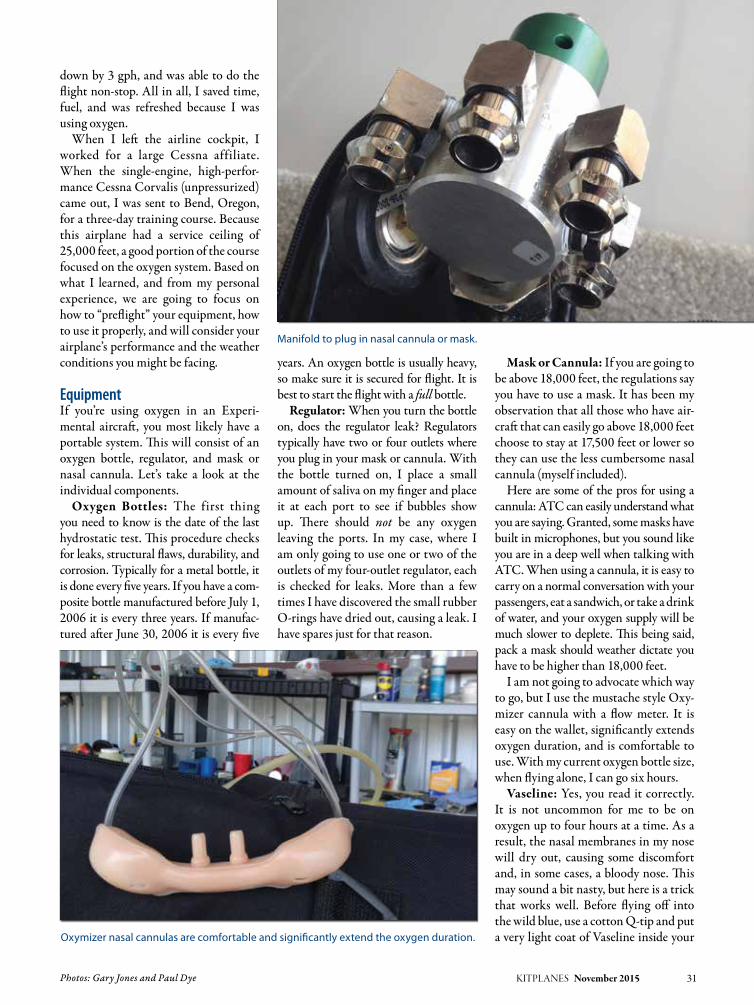
Photos: Gary Jones and Paul Dye KITPLANES November 2015 31
down by 3 gph, and was able to do the flight non-stop. All in all, I saved time, fuel, and was refreshed because I was using oxygen.
When I left the airline cockpit, I worked for a large Cessna affiliate. When the single-engine, high-perfor-mance Cessna Corvalis (unpressurized) came out, I was sent to Bend, Oregon, for a three-day training course. Because this airplane had a service ceiling of 25,000 feet, a good portion of the course focused on the oxygen system. Based on what I learned, and from my personal experience, we are going to focus on how to “preflight” your equipment, how to use it properly, and will consider your airplane’s performance and the weather conditions you might be facing.
EquipmentIf you’re using oxygen in an Experi-mental aircraft, you most likely have a portable system. This will consist of an oxygen bottle, regulator, and mask or nasal cannula. Let’s take a look at the individual components.
Oxygen Bottles: The first thing you need to know is the date of the last hydrostatic test. This procedure checks for leaks, structural flaws, durability, and corrosion. Typically for a metal bottle, it is done every five years. If you have a com-posite bottle manufactured before July 1, 2006 it is every three years. If manufac-tured after June 30, 2006 it is every five
years. An oxygen bottle is usually heavy, so make sure it is secured for flight. It is best to start the flight with a full bottle.
Regulator: When you turn the bottle on, does the regulator leak? Regulators typically have two or four outlets where you plug in your mask or cannula. With the bottle turned on, I place a small amount of saliva on my finger and place it at each port to see if bubbles show up. There should not be any oxygen leaving the ports. In my case, where I am only going to use one or two of the outlets of my four-outlet regulator, each is checked for leaks. More than a few times I have discovered the small rubber O-rings have dried out, causing a leak. I have spares just for that reason.
Mask or Cannula: If you are going to be above 18,000 feet, the regulations say you have to use a mask. It has been my observation that all those who have air-craft that can easily go above 18,000 feet choose to stay at 17,500 feet or lower so they can use the less cumbersome nasal cannula (myself included).
Here are some of the pros for using a cannula: ATC can easily understand what you are saying. Granted, some masks have built in microphones, but you sound like you are in a deep well when talking with ATC. When using a cannula, it is easy to carry on a normal conversation with your passengers, eat a sandwich, or take a drink of water, and your oxygen supply will be much slower to deplete. This being said, pack a mask should weather dictate you have to be higher than 18,000 feet.
I am not going to advocate which way to go, but I use the mustache style Oxy-mizer cannula with a flow meter. It is easy on the wallet, significantly extends oxygen duration, and is comfortable to use. With my current oxygen bottle size, when flying alone, I can go six hours.
Vaseline: Yes, you read it correctly. It is not uncommon for me to be on oxygen up to four hours at a time. As a result, the nasal membranes in my nose will dry out, causing some discomfort and, in some cases, a bloody nose. This may sound a bit nasty, but here is a trick that works well. Before flying off into the wild blue, use a cotton Q-tip and put a very light coat of Vaseline inside your Oxymizer nasal cannulas are comfortable and significantly extend the oxygen duration.
Manifold to plug in nasal cannula or mask.
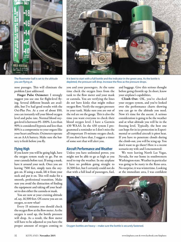
nose passages. This will eliminate the problem I just addressed.
Finger Pulse Oximeter: I strongly suggest you use one for flight-level fly-ing. Several different brands are avail-able, but I’ve had good results with the Oxi-Plus Pro. At a cost of about $50, you can instantly tell your blood oxygen level and pulse rate. Normal blood oxy-gen level is between 95–100%. Less than 90% is considered hypoxia and less than 80% is a compromise to your organs like your heart and brain. Oximeters operate on an AAA battery. Make sure the bat-tery is fresh before you fly.
Flying HighIf you know you will be going high, have the oxygen system ready to go. Put on your cannula before taxi. If using a mask, have it around your neck. Once you are leaving 7500 feet, simply turn the oxy-gen on. If using a mask, lift it from your neck and put it on. This will make for a smooth, professional transition. Make sure you avoid the distraction of finding the equipment and taking off your head-set to don either the cannula or mask.
You are now at your cruising altitude of, say, 16,500 feet. Of course you are on oxygen, so now what?
Every 15 minutes you should check the oxygen flow at the flow meter. As the oxygen is used up, the bottle pressure will drop. As a result, the flow meter will have to be adjusted so you have the proper amount of oxygen coming to
you and your passengers. At the same time check the oxygen lines from the tank to the flow meter and your mask or cannula. You are verifying the lines do not have kinks that might reduce oxygen flow. Verify the oxygen pressure in your tank. Make sure you are out of the red arc on the gauge. This is also the time you want everyone to check their blood oxygen level. I have a Garmin 430 WAAS. In the 430 system I pro-grammed a reminder so I don’t miss the all-important 15-minute oxygen check. If you don’t have that, I suggest a timer of some sort that will alert you.
Aircraft Performance and WeatherUnless you have unlimited power, you might not be able to go as high as you need to top the weather. In my airplane I have no problem going straight to 16,500 feet, but I certainly could not do that with a full load of passengers, fuel,
and baggage. Give this serious thought before going throttle up. In short, know your airplane’s capabilities.
Climb-Out: OK, you’ve checked your oxygen system, and you’ve looked over the performance charts showing you can go to the altitude you need. Now it’s time for the ascent. A serious consideration is going to be the weather and at what altitude you will be in the freezing level. Typically, the best one can hope for in ice protection in Experi-mental or certified aircraft is pitot heat. If you have to penetrate clouds during the climb-out, you will be icing up. You don’t want to go there! Here is a recent scenario my wife and I encountered:
We were leaving North Las Vegas, Nevada, for our home in southwestern Washington state. Weather in particular was going to be nasty in the Reno area. No surprise; it was wintertime. Looking at the immediate area, I was confident
32 KITPLANES November 2015 www.kitplanes.com & www.facebook.com/kitplanes
It is best to start with a full bottle and the indicator in the green area. As the bottle is depleted, the pressure will drop. Increase the flow as the pressure drops.
Oxygen bottles are heavy—make sure the bottle is securely fastened.
The flowmeter ball is set to the altitude you are flying at.

we could get out of Las Vegas before hitting icing conditions. But would we be able to stay in the clear to continue up to 16,500 feet? That question was answered by scrutinizing the weather information. The question I could not answer by doing this was: What were the actual tops along the route and, in particular, around the Reno area? For this I called FSS, told them my situation and asked them to contact ATC and have ATC ask an airliner. Within a min-ute, the answer came back—15,000 feet.
By following the procedures I pre-viously mentioned in this article, the flight was a pleasant one, with lots of sunshine and a fuel burn of 7.3 gph. We didn’t make record speeds, but we were safe and comfortable.
Descent: The same weather concerns that exist for the climb also need to be addressed in the descent. I was on a non-stop flight in my Glasair from the Denver area to my Washington home. At 14,500 feet and above the icing con-ditions that lay below, the flight was pleasant. As I monitored the weather, I noticed that freezing temperatures went down to the ground at my home airport. I also had to descend through 8,000 feet of clouds that were full of ice.
Prior to reaching the Cascade Moun-tains, there was a large VFR hole. I circled to descend below the clouds. By staying out of the clouds in below-freez-ing temperatures, my plane never picked up ice. With a 3,000-foot ceiling, it was a simple matter of flying home under the clouds in VFR weather. When you use common sense and properly use a portable breathing system, flying high is enjoyable and safe. J
KITPLANES November 2015 33
GARY JONES
Gary Jones has built a Q2, Q200, and Glasair Super II-S FT. A retired airline captain, he now works as a stand-up comedian. Gary performs at major casinos and comedy clubs, and has entertained our military on a USO tour. His web site is www.garyjonescomedian.com.
Print and Digital
Either Format – Great Savings!Subscribe Now at www.kitplanes.com/subscribe

www.kitplanes.com & www.facebook.com/kitplanes34 KITPLANES November 2015
Spirit of St. Louis
John Norman’s definitive reproduction of the Spirit of St. Louis in progress at JNE Aircraft in Burlington, Washington. (Photo: Kristopher L. Hull)
Original Spirit of St. Louis at the Smithsonian Air and Space Museum in
Washington, D.C. (Photo: Mike Peel, CC BY-SA 4.0
www.mikepeel.net)
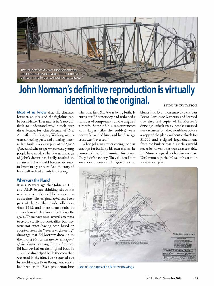
Photos: John Norman KITPLANES November 2015 35
John Norman’s definitive reproduction is virtually identical to the original.
By DaviD Gustafson
Most of us know that the distance between an idea and the flightline can be formidable. That said, it isn’t too dif-ficult to understand why it took over three decades for John Norman of JNE Aircraft in Burlington, Washington, to start collecting parts and ordering mate-rials to build an exact replica of the Spirit of St. Louis…in an age when many young people have no idea what it was. The saga of John’s dream has finally resulted in an aircraft that should become airborne in less than a year now. And the story of how it all evolved is truly fascinating.
Where are the Plans?It was 35 years ago that John, an I.A. and A&P, began thinking about his replica project. Seemed like a nice idea at the time. The original Spirit has been part of the Smithsonian’s collection since 1928, and there is no doubt in anyone’s mind that aircraft will ever fly again. There have been several attempts to create a replica, or look-alike, but they were not exact, having been based or adopted from the “reverse engineering” drawings that Ed Morrow drew up in the mid-1950s for the movie, The Spirit of St. Louis, starring Jimmy Stewart. Ed had worked on the original back in 1927. He also helped build the copy that was used in the film, but he started out by modifying a Ryan Brougham, which had been on the Ryan production line
when the first Spirit was being built. It turns out Ed’s memory had reshaped a number of components on the original aircraft. Some of his measurements and shapes (like the rudder) were pretty far out of line, and his fuselage truss was “reversed.”
When John was experiencing the first cravings for building his own replica, he contacted the Smithsonian for plans. They didn’t have any. They did send him some documents on the Spirit, but no
blueprints. John then turned to the San Diego Aerospace Museum and learned that they had copies of Ed Morrow’s drawings, which many people assumed were accurate, but they would not release a copy of the plans without a check for $1,000 and a signed legal document from the builder that his replica would never be flown. That was unacceptable. Ed Morrow agreed with John on that. Unfortunately, the Museum’s attitude was intransigent.
Spirit of St. Louis
The JNE Spirit of St. Louis’ fuselage after its return from the sandblaster. The author has painted it and begun to install parts (seat, etc.).
One of the pages of Ed Morrow drawings.

When he approached the EAA about the replica they had built, which had a shorter wingspan, a smaller eleva-tor, and a number of other concessions in the interest of safety, remarkably, John was told in no uncertain terms that he shouldn’t attempt to build and fly a copy of the Spirit. EAA and the San Diego Museum dampened John’s mood, but didn’t kill the dream. John
had a young family to support, so he back-burnered the project…for over 30 years. (Today, he does the preflight and inspection on 787s before releasing the aircraft to their owners.)
The Rib JigIn 2011 John visited the San Diego Aerospace Museum and learned that they had a jig for making up ribs that
had been used for the movie’s replica. The ribs were accurate. The Museum was selling them to raise money for their programs. John purchased one and was so impressed with the quality and the purpose that a year later, he contacted them and ordered a complete set. They agreed, but cautioned it could take up to a year and a half to finish all 50 ribs. John was in no rush and turned to research on the Spirit. “I bet I invested between 1,000 and 2,000 hours in research,” he said. Most of that time was spent in front of a computer.
When John ordered his set of ribs, he learned that the Museum, as the result of an alleged lawsuit, had gone through a change of heart with respect to Ed Mor-row’s plans. They sent him a set on a CD free of charge and had no restrictions about flying a replica. It was a welcomed example of “legal” enlightenment.
Funding the ProjectJohn has restored a number of air-craft over the years. When he sold the Hawker Hurricane project that filled his shop in 2012, he used some of the proceeds to purchase parts and mate-rials needed to build the Spirit of St. Louis. The ribs were ordered in January 2012 and came in batches of 8 until he had a complete set. In April, 2012, he sold a J-3 project to someone in China
36 KITPLANES November 2015 www.kitplanes.com & www.facebook.com/kitplanes
The JNE Spirit of St. Louis going together in 2015 with stringers, main fuel tank, motor mount with motor mount fuel tank and oil tank installed.
Throttle and mixture control levers, trimtab quadrant, stick, and wicker seat installed in the JNE Spirit of St. Louis.

and used the funds from that to pur-chase tubing for the Spirit fuselage. With that, he was committed, and all of his spare time was logged in the shop or pursuing information or materials for his replica.
Like instruments. John wanted exact copies of every-
thing in the panel. “The problem is, all the original instruments from that era are in the hands of collectors, and most of them don’t want to break up their col-lection.” Between eBay and networking, John and his wife Heather eventually tracked down and acquired the basic instruments. However, since most of them had been sitting idle on various shelves for over 80 years, they all needed to be rebuilt. The total cost for the panel is north of $8,000.
Once committed, John made good progress. He tack-welded the fuselage frame. He built up the I-beam spars working with 36-foot pieces of Sitka spruce and slid on the ribs. As a conces-sion to safety, John reduced the number of splices in the wing from 28 to 10. He eventually was able to assemble all of the major components, tail feathers, wings, fuselage, instrument panel, and engine mount, before he took it all apart and sent out the steel parts for sandblasting. When it returned, he painted the steel truss himself.
Measuring the OriginalIn January of 2015, the Smithsonian lowered the Spirit to the floor of the National Air and Space Museum for the third time since they’d taken possession of it in 1928. John was granted a full day to photograph and measure everything he could reach on the Spirit. Mindful that the Spirit is a national treasure, the museum had several people on hand to keep an eye on John and Heather, and they worked through a typical day in the museum, with crowds gather-ing around the aircraft and wondering what was going on. RF Systems Lab of Traverse City, Michigan, donated the use of a VJ-Advance video borescope camera for John to use with the Spirit of St. Louis. When he was looking under the main fuel tank, he suddenly uttered something like “holy crap!”. The museum executives were watching the monitor as John focused on a pair of pliers lying on fabric beneath the tank. Given the dust on the tool, it had been there for a very long time. The question is: How long? The Smithsonian is still looking for answers. The assumption is that they have been there since at least May of 1928.
What John got out of his day with the Spirit was the realization that Ed Morrow’s memory wasn’t as exact as John’s measurements. There were at
least nine components in John’s replica that needed change. This included the elevator, which was 2.5 inches shorter between the leading and trailing edges than the original. When John restruc-tured his elevator, he added 190 square inches to his tail. It’s worth noting that the dimensions John had originally come up with were based on the tail feathers for a Ryan M1 and M2, which were the first two aircraft produced by the Ryan factory. There undoubtedly were a number of parts from the M1 and M2 that were picked off the shelf and put into the Spirit. But as far as the tail goes, the elevator and horizontal sta-bilizer probably came off a Brougham, Ryan’s third aircraft, the prototype of which was being built at the same time as the Spirit. The rudder profile differs considerably from Ed Morrow’s half circle, which came from an M1, and no
KITPLANES November 2015 37
The cockpit area after rebuilding the instrument panel.
The instrument panel of the JNE Spirit of St. Louis in 2013 before being rebuilt. (Photo: Kristopher L. Hull)
The pliers found with RF Systems Lab’s VJ-Advance video borescope camera were lying on the fabric beneath the main fuel tank in the original Spirit of St. Louis.
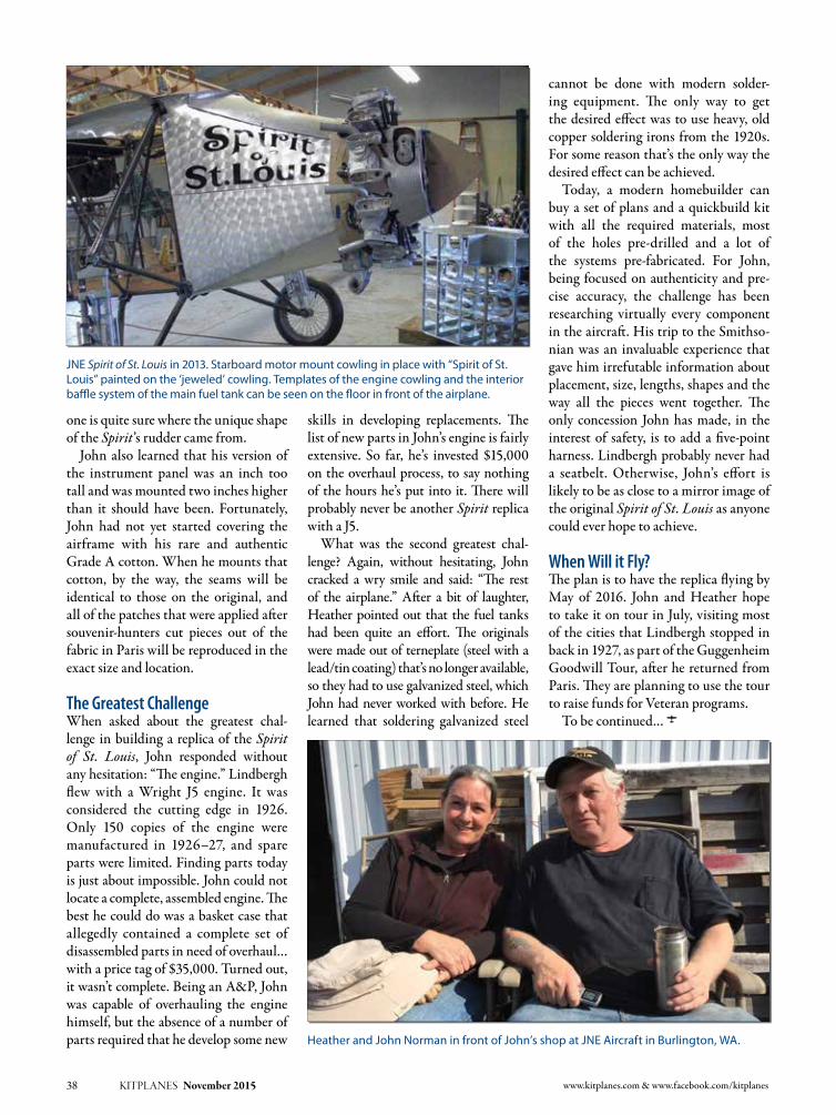
one is quite sure where the unique shape of the Spirit’s rudder came from.
John also learned that his version of the instrument panel was an inch too tall and was mounted two inches higher than it should have been. Fortunately, John had not yet started covering the airframe with his rare and authentic Grade A cotton. When he mounts that cotton, by the way, the seams will be identical to those on the original, and all of the patches that were applied after souvenir-hunters cut pieces out of the fabric in Paris will be reproduced in the exact size and location.
The Greatest ChallengeWhen asked about the greatest chal-lenge in building a replica of the Spirit of St. Louis, John responded without any hesitation: “The engine.” Lindbergh flew with a Wright J5 engine. It was considered the cutting edge in 1926. Only 150 copies of the engine were manufactured in 1926–27, and spare parts were limited. Finding parts today is just about impossible. John could not locate a complete, assembled engine. The best he could do was a basket case that allegedly contained a complete set of disassembled parts in need of overhaul…with a price tag of $35,000. Turned out, it wasn’t complete. Being an A&P, John was capable of overhauling the engine himself, but the absence of a number of parts required that he develop some new
skills in developing replacements. The list of new parts in John’s engine is fairly extensive. So far, he’s invested $15,000 on the overhaul process, to say nothing of the hours he’s put into it. There will probably never be another Spirit replica with a J5.
What was the second greatest chal-lenge? Again, without hesitating, John cracked a wry smile and said: “The rest of the airplane.” After a bit of laughter, Heather pointed out that the fuel tanks had been quite an effort. The originals were made out of terneplate (steel with a lead/tin coating) that’s no longer available, so they had to use galvanized steel, which John had never worked with before. He learned that soldering galvanized steel
cannot be done with modern solder-ing equipment. The only way to get the desired effect was to use heavy, old copper soldering irons from the 1920s. For some reason that’s the only way the desired effect can be achieved.
Today, a modern homebuilder can buy a set of plans and a quickbuild kit with all the required materials, most of the holes pre-drilled and a lot of the systems pre-fabricated. For John, being focused on authenticity and pre-cise accuracy, the challenge has been researching virtually every component in the aircraft. His trip to the Smithso-nian was an invaluable experience that gave him irrefutable information about placement, size, lengths, shapes and the way all the pieces went together. The only concession John has made, in the interest of safety, is to add a five-point harness. Lindbergh probably never had a seatbelt. Otherwise, John’s effort is likely to be as close to a mirror image of the original Spirit of St. Louis as anyone could ever hope to achieve.
When Will it Fly?The plan is to have the replica flying by May of 2016. John and Heather hope to take it on tour in July, visiting most of the cities that Lindbergh stopped in back in 1927, as part of the Guggenheim Goodwill Tour, after he returned from Paris. They are planning to use the tour to raise funds for Veteran programs.
To be continued… J
38 KITPLANES November 2015 www.kitplanes.com & www.facebook.com/kitplanes
Heather and John Norman in front of John’s shop at JNE Aircraft in Burlington, WA.
JNE Spirit of St. Louis in 2013. Starboard motor mount cowling in place with “Spirit of St. Louis” painted on the ‘jeweled’ cowling. Templates of the engine cowling and the interior baffle system of the main fuel tank can be seen on the floor in front of the airplane.

More than a timepiece.Less than a flight deck.
©2015 Garmin Ltd. or its subsidiaries
D2 BRAVO
Introducing the new Garmin D2™ Bravo GPS pilot watch. First we invented wrist-worn portable navigation.
Now, we’ve made it even lighter, thinner and better: With new easy-to-access METARs aviation weather, Direct-To
and Nearest functions, worldwide airport database, smartphone text/alert connectivity, Garmin Pilot® alerts, optical
sapphire lens and color display – plus wireless control for our VIRB HD action camera, and more.
For a closer look, visit Garmin.com/aviation or see your Garmin dealer
24957 D2 Bravo Ad-Kitplanes.indd 4 6/5/15 2:12 PM

www.kitplanes.com & www.facebook.com/kitplanes40 KITPLANES November 2015
By DaviD Paule
The stress is zero at the neutral axis and increases linearly as the distance from it increases. This means that at the out-ermost edge of the beam, farthest from the neutral axis, which we call the “outer fiber,” the stress is at maximum. But there’s still stress between the top and bottom outer fibers, and those places need to be able to carry that stress.
M is the bending moment, inch pounds force,
c is the distance from the neutral axis to the place where the stress is, inches
I is the area moment of inertia about the neutral axis, inches4
This is the fundamental equation for bending. The equation tells us a few important things. If the bending moment goes up, the stress does too, proportionally. If the stress is too high, you would increase the moment of iner-tia to make it go down. And the equa-tion also tells us the stress is directly proportional to the distance from the neutral axis.
Figure 1 shows how the bending stress distributes itself across a symmetric beam.
Most major structures on an aircraft need to support some bending. In this article, we’ll look at how a beam resists bending and how to find the bending stress. There are a variety of convenient tables in the Astronautics Structures Manual (www.kitplanes.com/includes/structure_stress.html) to help you actually calculate the bending moment using the loads that are applied to the beam. Look in Section B4.1.1 in asm-B400.pdf. Here, we’ll discuss what to do with the bending moment once you have it.
You can find the beam stress by using this equation:
Whereσ is the bending stress in psi,
Stressing Structure
Bending The very pretty spars for the author’s RV-3B
are important enough that Van’s Aircraft sent
them pre-assembled.
Figure 1: Bending stress distribution across a beam.
M * c σ = I

If there’s an axial force in the beam as, for example, there will be inboard of the struts for a strut-braced airplane, then it needs to be included. In that case, the stress is:
WhereP is the axial force, pounds,A is the cross-sectional area,
square inches.
An axial stress can significantly change the stresses in a beam.
We’ll need to find the margin of safety at the tension outer fiber and the compression outer fiber, for the highest positive moment and the highest nega-tive moment. When we do that, and show that the margin is positive, we’ve shown that the beam is at least safe in bending, which is all we’re discussing in this article. The beam might also have shear and axial compression, both of which affect stability, so then you need to analyze the beam for those loads, too, but that’s beyond this article.
Where should we check the beam? Anywhere the cross-section changes, anywhere there’s an abrupt change of load, and anywhere the load is a maximum. As an example, consider a strut-braced wingspar. For a positive flight condition, the maximum posi-tive moment will be at the intersection of the strut. Immediately outboard of that point there’s generally zero axial force. The spar needs to be checked there. Somewhere in between the strut and the fuselage, the maximum nega-tive moment might exist. It will have axial force in addition to the bending,
and that adds to the load. If there’s a point load, from a control system or flap mount or something, check it there too. And wherever there’s a fitting or a hole, the spar will need to be checked. If the spar changes cross section, we’ll want to assess those locations as well.
When you’re figuring out the spar sec-tion to use for analysis, be sure to include any holes that are nearby the section. Holes count as gaps, with one excep-tion: hole-filling fasteners like driven rivets can be used if carrying compres-sion—but only compression—and even then only the shank can be used, not a countersunk head or a dimple. Dimples and countersinks act like holes.
See Figure 2, which shows a cross-section of an aluminum extrusion. This extrusion uses three of the fundamen-tal shapes that are often used to assess beams. The sidebar on section properties shows how to calculate the properties of the more common basic cross sectional shapes. If you need a shape that’s not in the sidebar, you can look it up online.
Now we’ll calculate the section prop-erties of this beam. We’ll find the area, the moment of inertia, and the location of the neutral axis. We start with Table 1, which shows the salient facts of the individual elements in the spar.
Using the information in Table 1 and the sidebar on section properties, we next calculate some data for the spar, putting the section properties into a table like Table 2. The columns include:
Item An identifier. I number my elements.
A The area of the cross-section, inches squared. If it’s a hole, it’s negative.
KITPLANES November 2015 41 Illustrations: David Paule
Stressing Structure P M * c σ = + A I
Figure 2: An example cross-section of an extruded beam.
Formulas for Section PropertiesTubeArea = ∏ (R2 – r2)Inertia = ∏ (R4 – r4)
Triangle 1Area = • B • H 2 Hybar = 3 B • H3
Inertia = 36
RectangleArea = B • H Hybar = 2 B • H3
Inertia = 12
Bend ∏ Area = • (R2 – r2) 4 r2
ybar = .4244 • ( R + ) R + r
∏ Inertia = • (R4 – r4) 16
FilletArea = .2146 • R2
ybar = .2234 • R
Inertia = .0075 • R4
Rectangle with Symmetric Rectangular Opening
Area = B • H – b • h Hybar = 2 1 Inertia = • (B • H3 – b • h3) 12
Item No. What is it? Dimensions, inches Notes
1 Top cap–rectangle B = 1.00, H = .325, y = 2.8375 y = 3.00 - .325 / 2
2 Web–rectangle B = .120, H = 2.405, y = 1.4725
H = 3.00 - .325 - .120 - .150y = H / 2 + .120 + .150
3 Bottom flange–rectangle B = .82, H = .120, y = .060 y = H / 2
4 Hole–rectangle B = .120, H = .120, y = .060 y = H / 2
5 Fillet R = .150, y = 2.6415 y = 3.00 - .325 - .2234 • R
6 Bend radius R = .270, r = .150, y = .1327 Outer radius r = .150 + .120 thickness. y = R - ybar equation for bend
Table 1: Geometry of the Example Beam’s Individual Elements

ct = 3.00 - 1.8466 = 1.1534 inches to the top surface.
cb = 1.8466 inches to the bottom surface.
Finally, we can find the stress:ft = 17,900 • 1.1534 / .8897 = -23,205
psi for the top surface. It’s negative because the top surface is in compression.
fb = 17,900 • 1.8466 / .8897 = 37,152 psi tension on the bottom surface.
For now, we’ll have to use the ultimate tensile stress and the yield compressive stress as the allowable strengths, and calculate the ultimate margins of safety. This isn’t a conservative calculation though, because it didn’t cover buck-ling. In another article we’ll discuss crippling, a type of buckling instability that will reduce the strength of many beams and other structures. Crippling or other types of buckling are prevalent all through aircraft construction and are a major design issue.
FSu = 1.5 Ultimate factor of safety.
Ftu = 63,000 psi Ultimate tensile strength of 2024-T3, .063 thick (or 2024-T351 plate, thick enough to be made into a cap).
Fcy = 39,000 psi Yield compression strength for these materials.
The margins of safety are:For the top, in compression (and worth
noting here that often in the margin of safety equation, the minus signs are unnec-essary; I’ve included them for clarity):
42 KITPLANES November 2015 www.kitplanes.com & www.facebook.com/kitplanes
y The distance from the reference to the neutral axis (the x-x axis) of this element. Positive is upward from the reference line and below it, y is negative.
A • y Multiply the element’s area by its distance.
A • y2 Multiply the A * y calculated value by y again.
Io Calculate the element’s own moment of inertia, about its own neutral axis.
Remember, if a negative number multiplies a positive number, the result is a negative number. If you multiply two negative numbers together, the result is positive.
The bottom row of the table gives us the overall properties of the beam.
A Sum the individual element areas and put the total here. Units are inches2.
A • y Sum the individual element area • distance and put the total here. Units are inches3.
A • y2 Sum the individual element area • distance squared and put the total here. Units are inches4.
Io Sum the individual element inertias and put the total here. Units are inches4.
Then under the table, make these calculations:
Ybar, with units of inches, is the posi-tion of the neutral axis from the refer-ence for your beam. Incidentally, in this article, I’m using ybar to indicate the individual element property and with-out the subscript Ybar to indicate the overall beam’s property.
We can find the spar’s moment of inertia, using the values summed at the bottom of the table:
I = Sum (A • y2) + sum (Io) - sum (Area) • ybar2
“I” is the overall moment of iner-tia for the beam. It’s more formally called the “area moment of inertia” to differentiate it from the mass moment of inertia. However, usually during stress analysis, we drop the word “area” because the meaning is clear from the context.
Once in a while, when considering buckling situations, we’ll also need to find the radius of gyration, ρ:
ρ = [I / A]1/2
Or another way to describe it is:
ρ2 = I / A
If you need it, use whichever form is appropriate. Physically, it’s the radius from an axis about which the area is distributed, if it were all located in a ring about the axis. That descrip-tion’s not useful and I much prefer the equation.
For our example, to tie the data into the previous figures and analysis.
Area = 0.7420 inch2
Ybar = 1.3702 / 0.7420 = 1.8466 inches
I = 3.2770 + .1430 - 0.7420 • 1.84662 = .8897 inch4
Now that we’ve done the hard work, we can find out what the stresses are on the beam. We need to know what the bending moment is. For this example, that’s 17,900 inch-pounds force, and that’s the ultimate moment. These moments are positive, and by definition that means the compression stresses are on the top. We also need “c,” the distance from the neutral axis to the outer fiber.
Sum A • y Ybar = Sum A
Item No. A y A • y A • y2 Io
1 0.325 2.8375 0.9222 2.6167 0.0029
2 0.2886 1.4725 0.4250 0.6258 0.1391
3 0.0984 0.06 0.0059 0.0004 0.0001
4 -0.0144 0.06 -0.0009 -0.0001 0
5 0.0048 2.6415 0.0127 0.0335 0
6 0.0396 0.1327 0.0053 0.0007 0.0009
Sum 0.7420 1.3702 3.2770 0.1430
Table 2: Example—A Cross Section of an Extruded Beam.

For the bottom, in tension:
It’s normal good practice to include the + signs in the result to make cer-tain that readers understand that your margins of safety are positive. We’d also note which load condition produces these margins, important since another load condition will give different mar-gins of safety.
Another approach to finding the strength of a metal beam is to use a concept called “plastic bending.” In some cases, plastic bending will provide higher strength than using the ulti-mate tensile strength of the material. The increase in strength is dependent upon the shape and the material. You can read more about it in ASM section B4.5.0. If buckling is critical, though, plastic bending might not help much. The bending strengths of wood beams include the shape characteristics, if you follow ANC-18.
In some cases, the fatigue life of a beam can be important and that might also affect the allowable stress on the beam, especially if there are changes of contour or holes. These things are beyond the scope of this article as well. J
KITPLANES November 2015 43
DaviD Paule David Paule retired after 30 years of structural analysis and is now building an RV-3B to keep from getting bored. The structural engineering included a mix of aircraft and spacecraft. He has been a private pilot since age 18 and currently owns and flies a Cessna 180.
-39,000 psiMS = – 1 = +0.120 1.5 • (-23,205 psi)
63,000 psiMS = – 1 = +0.130 1.5 • (37,152 psi)

www.kitplanes.com & www.facebook.com/kitplanes44 KITPLANES November 2015
energy available for engine breathing depends on density altitude, so a cold day at sea level means the engine can aspirate more air mass than during a hot day in Denver or at 50,000 feet. And it’s the mass of air, not the volume, that matters.
Getting air and fuel into the engine.By Tom Wilson
Those not put to sleep by last month’s overview of aircraft engine principles will recall a piston engine’s working medium is air. This month we’ll exam-ine how the engine breathes in its air and adds fuel to the fire, a topic generally referred to as intake or induction.
Because the topic is so large, we’re also breaking induction into three major sec-tions. This month we’ll look at general basics and how they apply to carbureted engines. We’ll tackle fuel injection and forced induction—turbos and such—in separate articles.
Textbook BasicsBefore getting into describing intake hardware, a quick review of engine breathing concepts and nomenclature will assure we’re all on the same page.
It’s useful to remember air enters the engine thanks to the weight of the atmo-sphere above the engine pushing the air down. In other words, as the engine’s intake valve opens, it’s the weight of the atmosphere that pushes air into the cyl-inder. This is called natural aspiration and is the norm for most Experimental aircraft engines. Obviously the air and
Air filter to intake port: The entire induction system is out in the breeze on the Tymc-zyszyn family’s 1931 Buhl LA-1 Bull Pup. The compact A-65 Continental engine allows equal-length intake runners (chromed) from the centrally mounted carburetor. Amazingly little has changed at the low-performance end of aero engine induction in the 56 years since this installation.
Intake Systems: Carburetion
ENGINE THEORY

Photos: Tom Wilson KITPLANES November 2015 45
As airplane people, most of us are at least conscious of aerodynamics, and it’s good to remind ourselves the aerody-namic properties at work on the outside of our airframes are also at work inside the intake tract. Ideally the intake tract will be carefully shaped to maintain the optimal volumes, cross sectional areas, and remain devoid of sharp edges, pinched turns, and other aerodynamic insults. All this matters in the intake tract where tight packaging and low-energy airflow (compared to exhaust) magnify design imperfections. The less your inlet resembles a Sousaphone or a half-crushed shoebox the better.
The Air PathIn practice air begins its journey to the combustion chamber at the air inlet, which may or may not include an air filter. Also, faster homebuilts benefit from a ram air intake where a dedicated scoop packs in slightly more air than the engine can breathe for a minor super-charging effect. In that case the air filter is typically bypassed once airborne to maximize airflow.
Because engine load, and secondarily rpm, is most easily controlled in gaso-line engines by throttling the engine’s air supply (turbines and diesels do this by limiting the fuel supply), some sort of throttle blade is typically the next item in our air passage. The throttle is contained either in a carburetor or fuel injection system’s throttle body. The lat-ter is traditionally called the fuel servo in aviation lingo because the industry stan-dard Bendix system combines the throt-tle body and fuel metering functions in a single unit, and the naming emphasis was apparently on the fuel side of things.
The carburetor is a mechanical device designed to mix the incoming air with gasoline to produce a combustible mix-ture. Therefore, downstream of the car-buretor, the inlet tract contains an air/fuel mix. This is not the case with fuel injection, as the fuel is added later, and so the inlet tract is “dry”—it flows only air.
From the throttle body the air or air/fuel mixture is conveyed to a cylinder via an intake runner. Most internal combustion engines group the runners,
or at least some portion of the runners, into a single casting or weldment called an intake manifold.
When the runner reaches the cylinder head, it mates with the intake port in the head. The port terminates at the intake valve seat, where, not surprisingly, the intake valve sits when it is not open. On the far side of the intake valve is the com-bustion chamber and a rather rude change in temperature for our air molecules.
For historical context, and to illus-trate there are actually many variations to intake architecture, the big radials and V-12s of yore typically used a pres-sure carburetor. Today we would call this single-point mechanical fuel injec-tion, but in the argot of the times, a “carburetor” (we’d call it a fuel servo today) metered the airflow and result-ing gasoline, plus provided the throttle. But instead of admitting the fuel to the airflow at the “carburetor,” the fuel was sprayed into the inlet track well down-stream by a single fuel injector. Typi-cally this high-volume lawn sprinkler was aimed at the supercharger’s inlet,
or, as in many radial engines, the fuel was actually slung from passages in the supercharger impeller. This helped even fuel delivery considerably among cylinders (which can be an issue in non-supercharged, carbureted radials).
Before leaving our overview of the intake system, we should touch on the concept of intake tuning. Obviously air does not flow as a steady stream through the inlet tract in a running engine. The rhythmic opening and closing of the intake valve, plus the variable energy (sometimes called the signal) imparted to the intake air by the downward moving piston, not to men-tion the mind-numbing complexities of these inlet pulses communicating in the intake manifold’s common area—the plenum—results in a very dynamic, pulsating environment.
In short, not only do the air molecules travel in a series of rapidly accelerat-ing and decelerating motions, but also meaningful energy waves are generated. It is far beyond the scope of this article to describe this complex, arcane wave
Cold air is dense air and thus better for engine breathing as well as oil cool-ing and other heat transfer tasks, so it’s worth the effort to build dedicated inlets whenever possible. Round motors do this by snaking scoops from the cowling entry to between engine cylinders and to the engine’s accessory section.
Most Experimentals have a forward-facing scoop dedicated to the engine air inlet, if only to ensure a cool, uncontaminated (no oil mist) air supply. Because airplanes are one of few machines that move fast and long enough to make ram air scoops worth the bother, the go-fast crowd often opts for a filterless ram-air scoop as mod-eled by this Harmon Rocket. Airspeed mat-ters; gains of 1 inch of manifold pressure are typical nearing 200 mph, faster Reno racers can see a 3-inch rise.

action, but suffice to say the intake run-ner length (especially), cross section, taper, total volume, and shape matter. Optimizing these parameters is called tuning by engine designers and pipe organ manufacturers; it significantly affects power and efficiency, and to the first order depends on cylinder displace-ment, rpm, and valve timing. These wave effects gain importance as an engine’s specific output (power per displace-ment) increases. It’s another reason why big, slow-turning engines have predomi-nated in aviation—such engines typi-cally require little intake tuning (simple, easily packaged intakes do OK).
Now we’ll examine carbureted and fuel injected systems in greater detail.
CarburetionAircraft carburetor sophistication these days ranges from a metered leak to a well-engineered metered leak. This basic carburetion helps affordability (if you can call a $27,000 engine affordable), and there’s always fuel injection when more efficiency is demanded.
Carburetors work on pressure dif-ferentials. Inside the carburetor a ven-turi constricts and then expands the airflow, generating a low-pressure area vented against higher ambient air pres-sure to push fuel from a small fuel reser-voir called the float bowl. Minimal fuel
pressure is needed to keep the float bowl at a steady level, and in high-wing aircraft gravity flow will do the job, so a simple, low-volume, low-pressure engine-driven fuel pump is all that’s needed.
Gravity is also used to keep the fuel level constant in the float bowl, so turning the airplane upside down for all but
positive-G maneuvers means fuel slosh in the bowl will cause extra rich or lean mixtures to the point the engine quits.
Several auxiliary circuits address the complications brought on by idling, maximum engine output, and transient response (engine acceleration). The idle circuit is a simple tiny passage better scaled to providing the small amount of fuel required when idling.
An accelerator pump is mechanically joined to the throttle linkage. This is a simple plunger to provide an extra squirt of fuel when the throttle is opened rap-idly. This is because lightweight air has low inertia and responds near-instantly to opening the throttle, while the heavier fuel lags. Absent an accelerator pump the resulting momentary lean air/fuel mixture is sufficient to invoke pas-senger interrogations when the engine momentarily quits every time the pilot gooses the throttle for a go-around.
Because a relatively rich air/fuel mixture is needed to produce maxi-mum power, and extra fuel on top of that is administered to cool the com-bustion event (suppress detonation), a fuel enrichment circuit opens as Wide
46 KITPLANES November 2015 www.kitplanes.com & www.facebook.com/kitplanes
One way of addressing poor mixture distribution from a single carburetor is multiple carburetors. The familiar Rotax 912 fits a Bing carburetor to each side of its flat-4 to shorten and simplify the intake manifolding. Cost, weight, and balancing the carburetor tuning are downsides, but it’s still less expense and effort than electronic fuel injection.
Because they are eyewitnesses to the laws of physics, carburetors can be remarkably simple considering the performance they produce. Unlike a man-made computer that must be pro-grammed for every foreseeable condi-tion, even the simple Marvel Schebler automatically responds directly to the air pressure passing through it.
Aircraft engines may toil mainly in the clean heavens, but they take off and land in the grit, just like cars and tractors. Furthermore, small vents and pressure-sensing tubes in fuel servos sometimes clog with insects, leading to major power losses. Best then to run an air filter, even if it only stops the boulders as this dirt-strip biplane’s filter attests.

Open Throttle (WOT) is reached. Inexplicably this was known as the “economizer” circuit in a fit of market-ing largesse during the 1950s and ’60s. Well, it was beneficial to the petro-leum company economies, so it’s all how you look at it.
Carburetion’s main advantages are simplicity and low cost. The carbure-tor is the only closely machined part in the system (and none too fancy at that), and it can be a pretty simple device on a moderate performance, steady-state rpm engine such as we fly with. Also, with a minimum of small passages, a carburetor is more forgiving of small junk in the fuel; it doesn’t clog anywhere near as quickly as fuel injection. Servic-ing and troubleshooting are simple, intuitive tasks, too.
Because the float bowl provides a ready supply of fuel at the engine, the engine can be primed by stroking the throttle, thus activating the accelerator pump. There is no need for a backup electric fuel pump for priming during engine starts.
A double-edged sword with carbure-tion is the fuel is administered to the engine at a single point well away from the intake ports. On the plus side, this gives the air and fuel more mixing time. This action provides evaporative
cooling for a denser charge, and all told, a sophisticated carbureted intake (not quite what we normally have in GA) can make excellent power at WOT, even outperforming electronic fuel injection. Yes, fuel distribution, lean-of-peak oper-ation, fuel economy, plug fouling, and reduced pilot workload can improve with fuel injection, but not necessarily peak power.
Experience shows carburetion’s peak power advantage from a denser charge is about 4%, and in highly developed engines, swapping from carburetion to fuel injection may show a peak power loss; NASCAR racers recently went though this when rules mandated a switch to fuel injection. That said, gen-eral aviation engine intake manifolds and carburetors are often basic enough that switching to fuel injection gains so much in better fuel distribution that there is a net gain in peak power.
As we just uncovered, the big down-side of carburetion’s single-point fuel distribution is the resulting “wet” mani-fold can’t help but deliver inconsistent mixtures among the cylinders. Fuel, with its greater inertia, can ram into sharp turns in the runners, while air easily whips around the corner. And inside long intake runners, fuel can condense from the mixture during cold
operations. All this is inefficient and eliminates the possibility of aggressive lean-of-peak operation as some cylin-ders may be quite lean and others still slightly rich of peak, right in the detona-tion window.
Carburetors are susceptible to icing as well. The trouble lies at the carb’s venturi, where the combination of the expanding air on the backside of the venturi, along with the fuel evapo-rating into the air stream, results in dramatic temperature reduction. As we learned in ground school, this is enough to cause the water in the air to freeze in the carburetor even on a 70° F day, choking off air supply and killing engine power. Some sort of carbure-tor heat is therefore required. Finally, because the float bowl relies on grav-ity carburetion has limits in aerobatic applications, too.
All said, carburetion is the cheap, sim-ple, reliable solution in general aviation engines as we know them. Those quali-ties continue to make carbureted engines logical choices in recreational aircraft. J
KITPLANES November 2015 47
Humble as it may be, the Bull Pup’s carburetor heat system clearly illustrates the concept. The only part not visible is the control cable to the mechanism’s air control flap inside the inlet box. Because hot air is less dense than cold air, there is always a performance drop when the carb heat is activated—but nothing like an ice-blocked carburetor!
Minus the exhaust it’s easy to see how this Lycoming 540’s intake runners sprout from the stock (hot) oil sump/intake manifold casting, then run to the cylinder heads. The cast portion of the runners inside the oil pan are bathed in 185°+ F oil, reducing intake icing when carbureted. Of course, this Bendix fuel injected example—note the fuel servo bolted to the bottom of the sump—doesn’t need any anti-icing help.
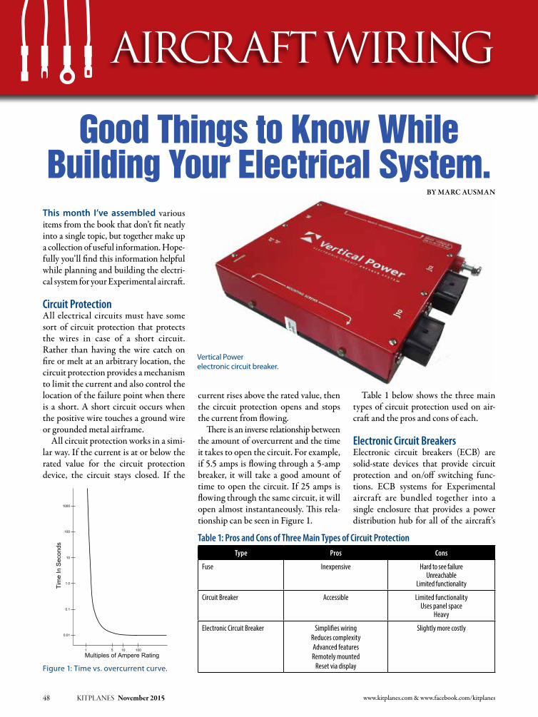
www.kitplanes.com & www.facebook.com/kitplanes48 KITPLANES November 2015
By Marc ausMan
Table 1 below shows the three main types of circuit protection used on air-craft and the pros and cons of each.
Electronic Circuit BreakersElectronic circuit breakers (ECB) are solid-state devices that provide circuit protection and on/off switching func-tions. ECB systems for Experimental aircraft are bundled together into a single enclosure that provides a power distribution hub for all of the aircraft’s
current rises above the rated value, then the circuit protection opens and stops the current from flowing.
There is an inverse relationship between the amount of overcurrent and the time it takes to open the circuit. For example, if 5.5 amps is flowing through a 5-amp breaker, it will take a good amount of time to open the circuit. If 25 amps is flowing through the same circuit, it will open almost instantaneously. This rela-tionship can be seen in Figure 1.
This month I’ve assembled various items from the book that don’t fit neatly into a single topic, but together make up a collection of useful information. Hope-fully you’ll find this information helpful while planning and building the electri-cal system for your Experimental aircraft.
Circuit ProtectionAll electrical circuits must have some sort of circuit protection that protects the wires in case of a short circuit. Rather than having the wire catch on fire or melt at an arbitrary location, the circuit protection provides a mechanism to limit the current and also control the location of the failure point when there is a short. A short circuit occurs when the positive wire touches a ground wire or grounded metal airframe.
All circuit protection works in a simi-lar way. If the current is at or below the rated value for the circuit protection device, the circuit stays closed. If the
Aircraft Wiring
Good Things to Know While Building Your Electrical System.
Figure 1: Time vs. overcurrent curve.
Vertical Power electronic circuit breaker.
1000
100
10
1.0
0.1
0.01
1
Multiples of Ampere Rating
Tim
e In
Sec
onds
5 10 100
Type Pros Cons
Fuse Inexpensive Hard to see failureUnreachable
Limited functionality
Circuit Breaker Accessible Limited functionalityUses panel space
Heavy
Electronic Circuit Breaker Simplifies wiringReduces complexityAdvanced featuresRemotely mounted
Reset via display
Slightly more costly
Table 1: Pros and Cons of Three Main Types of Circuit Protection
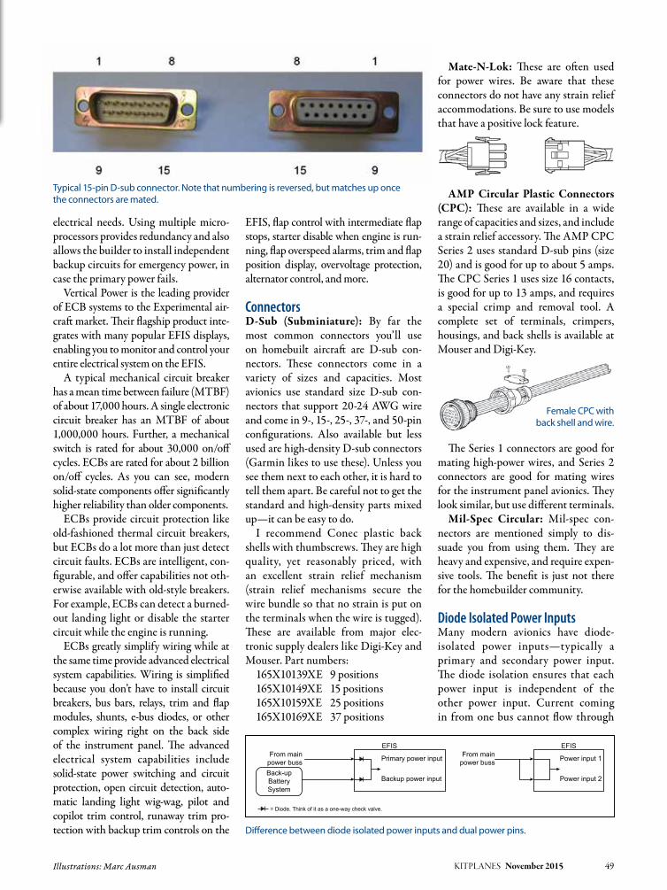
Back-upBatterySystem
EFIS
Primary power inputFrom mainpower buss
From mainpower buss
Backup power input
= Diode. Think of it as a one-way check valve.
EFIS
Power input 1
Power input 2
electrical needs. Using multiple micro-processors provides redundancy and also allows the builder to install independent backup circuits for emergency power, in case the primary power fails.
Vertical Power is the leading provider of ECB systems to the Experimental air-craft market. Their flagship product inte-grates with many popular EFIS displays, enabling you to monitor and control your entire electrical system on the EFIS.
A typical mechanical circuit breaker has a mean time between failure (MTBF) of about 17,000 hours. A single electronic circuit breaker has an MTBF of about 1,000,000 hours. Further, a mechanical switch is rated for about 30,000 on/off cycles. ECBs are rated for about 2 billion on/off cycles. As you can see, modern solid-state components offer significantly higher reliability than older components.
ECBs provide circuit protection like old-fashioned thermal circuit breakers, but ECBs do a lot more than just detect circuit faults. ECBs are intelligent, con-figurable, and offer capabilities not oth-erwise available with old-style breakers. For example, ECBs can detect a burned-out landing light or disable the starter circuit while the engine is running.
ECBs greatly simplify wiring while at the same time provide advanced electrical system capabilities. Wiring is simplified because you don’t have to install circuit breakers, bus bars, relays, trim and flap modules, shunts, e-bus diodes, or other complex wiring right on the back side of the instrument panel. The advanced electrical system capabilities include solid-state power switching and circuit protection, open circuit detection, auto-matic landing light wig-wag, pilot and copilot trim control, runaway trim pro-tection with backup trim controls on the
KITPLANES November 2015 49 Illustrations: Marc Ausman
EFIS, flap control with intermediate flap stops, starter disable when engine is run-ning, flap overspeed alarms, trim and flap position display, overvoltage protection, alternator control, and more.
ConnectorsD-Sub (Subminiature): By far the most common connectors you’ll use on homebuilt aircraft are D-sub con-nectors. These connectors come in a variety of sizes and capacities. Most avionics use standard size D-sub con-nectors that support 20-24 AWG wire and come in 9-, 15-, 25-, 37-, and 50-pin configurations. Also available but less used are high-density D-sub connectors (Garmin likes to use these). Unless you see them next to each other, it is hard to tell them apart. Be careful not to get the standard and high-density parts mixed up—it can be easy to do.
I recommend Conec plastic back shells with thumbscrews. They are high quality, yet reasonably priced, with an excellent strain relief mechanism (strain relief mechanisms secure the wire bundle so that no strain is put on the terminals when the wire is tugged). These are available from major elec-tronic supply dealers like Digi-Key and Mouser. Part numbers:
165X10139XE 9 positions165X10149XE 15 positions165X10159XE 25 positions165X10169XE 37 positions
Mate-N-Lok: These are often used for power wires. Be aware that these connectors do not have any strain relief accommodations. Be sure to use models that have a positive lock feature.
AMP Circular Plastic Connectors (CPC): These are available in a wide range of capacities and sizes, and include a strain relief accessory. The AMP CPC Series 2 uses standard D-sub pins (size 20) and is good for up to about 5 amps. The CPC Series 1 uses size 16 contacts, is good for up to 13 amps, and requires a special crimp and removal tool. A complete set of terminals, crimpers, housings, and back shells is available at Mouser and Digi-Key.
The Series 1 connectors are good for mating high-power wires, and Series 2 connectors are good for mating wires for the instrument panel avionics. They look similar, but use different terminals.
Mil-Spec Circular: Mil-spec con-nectors are mentioned simply to dis-suade you from using them. They are heavy and expensive, and require expen-sive tools. The benefit is just not there for the homebuilder community.
Diode Isolated Power InputsMany modern avionics have diode-isolated power inputs—typically a primary and secondary power input. The diode isolation ensures that each power input is independent of the other power input. Current coming in from one bus cannot flow through
Difference between diode isolated power inputs and dual power pins.
Typical 15-pin D-sub connector. Note that numbering is reversed, but matches up once the connectors are mated.
Female CPC with back shell and wire.

below. You’ll want to install, at minimum, one for the heavy-gauge wires, and another for the engine monitor and other smaller wires.
The firewall pass-through serves sev-eral purposes:
1. Reduces the chance of electrical wires chafing on the sharp firewall, which can lead to fires.
2. Reduces the chance of fire igniting in a crash.
3. Slows the penetration of a fire in the engine compartment.
4. Seals the firewall, reducing the chances of carbon monoxide or other gases entering the cabin. J
Read the Book Hopefully this article helps you under-stand the electrical system in your aircraft. It is an excerpt from my new book entitled Aircraft Wiring Guide. For more information, or to order a copy, visit www.aircraftwiringguide.com.
50 KITPLANES November 2015 www.kitplanes.com & www.facebook.com/kitplanes
the device and out the other pin to the other bus. The diodes shown can be thought of as check valves that ensure current only goes in—but does not come out—that particular power pin. The device will automatically choose between the inputs and select the one with the highest voltage.
The EFIS on the right in the example on page 49 does not have diode-isolated power inputs. It simply is using two power pins to distribute the current. Each pin can carry about 5 amps, and if the device draws 8 amps, the engineers decided to spread the load between two pins, so each carries 4 amps. Therefore, both pins must be fed from the same bus, and from the same circuit.
This can be easy to miss. Be sure to read the manufacturer’s instructions carefully to determine how the input power is handled.
Recommendations On Using 14 or 28 VoltsToday, most Experimental aircraft use a 14-volt electrical system, while most certified aircraft use a 28-volt electrical system. Components for 14-volt systems are easy to find, and often kit manufac-turers supply components that only work at a specific voltage (flap motors, for example). For the majority of Experi-mental aircraft, 14 volts is sufficient.
One reason to use 28 volts is to reduce wire size. The same device draws half as much current at 28 volts than it does at 14 volts. Therefore, you can size the wires smaller and save some weight. In a hypothetical Experi-mental aircraft with 600 feet of power and ground wire, if you use all 20
AWG wire instead of 18 AWG wire, the weight savings amounts to 1.5 lbs. Based on this analysis, weight alone should not be a deciding factor.
Most Experimental aircraft are small and have relatively short wire runs and relatively low-current devices. In such cases it makes sense to install a 14-volt system. However, you should consider a 28-volt system if you have an air condi-tioning system, or retractable gear that requires a hydraulic pump.
I also do not recommend installing two different buses with two different voltages. By the time you install the voltage converters and sort through the confusion of multiple voltages across multiple buses, it is better to stick with a common voltage for the entire aircraft.
Firewall PenetrationPrimary power distribution cables, engine monitor wires, and other wires like the starter control and alterna-tor field wire need to pass through the firewall. The firewall penetration must be secure so that hazardous gases do not get through, and it provides a barrier in case of an engine compartment fire.
Rather than run everything through one large hole, consolidate wires by function and run two or three smaller holes. There are several ways to do this:• DrillaholewithaUnibitstepdrill
and install a snap bushing. Run the wires, then fill in the hole with high-temperature silicon. While this does the job, it is not a very secure penetration.
• Installastainlesssteelfirewallpass-through as shown in the images
VO
LTS
14.2 volts (alternator ON)
13.0 volts (low-voltage alarm)
12.4 volts (battery only)
16.0 volts (over-voltage) Bus voltage should not exceed this level or damage to electronics may occur.
This is the normal operating voltage when the alternator is turned on and engine is running.
falls from 14.2 volts to around 12 volts, causing the low-voltage alarm to sound.
Normal voltage for the battery while not being charged.
Various firewall pass-through images showing installation. (Photos courtesy of SafeAir1)
Marc ausM
an
Marc currently flies an RV-7 that he finished building in 2006. He was founder and president of Vertical Power and has served as an EAA Director since 2011. He flew with the U.S. Navy as a Naval Flight Officer on board the P3-C Orion. He lives in California with his wife and three children.


52 KITPLANES November 2015 www.kitplanes.com & www.facebook.com/kitplanes
Skills transference, part 1.
CHECKPOINTS
Vic is a Commercial Pilot and CFII with ASMEL/ASES ratings, an A&P, DAR, and EAA Technical Advisor and Flight Counselor. Passionately involved in aviation for over 36 years, he has built 10 award-winning aircraft and has logged over 7800 hours in 69 different kinds of aircraft. Vic had a career in technology as a senior-level executive and volunteers as a Young Eagle pilot and Angel Flight pilot. He also has his own sport aviation business called Base Leg Aviation.
Vic Syracuse
In most journeys there is usually a des-tination. For many pilots that destination is the left seat at a major airline, a journey that is probably not unlike Hercules’ trials given all of the mergers, acquisitions, and furloughs in the industry. It’s interesting to me that many airline pilots see general aviation as a destination when retiring from the airline, especially with all of the exciting choices in sport planes now.
Having been primarily a general avia-tion pilot mainly focused on kitbuilt airplanes, with a small stint in part 121 regional carrier flying, I have some observations regarding the transfer-ence of skills from one type of flying to another, as well as my own experiences with regards to similarities and differ-ences between the two. This will be a multi-column saga, so hang on. Also, I am not here to disparage anyone. We are all brethren of the wings, so to say.
Between living in an aviation commu-nity and hanging out with a great group of pilots called the Falcon RV squadron, based at Falcon Field in Peachtree City, Georgia, I get to regularly see many aspects of the spectrum. Both groups encompass a great cross-section of pilots from all walks of aviation—pure general aviation, military, airline, and corporate—probably not unlike many flying clubs throughout the world.
Here’s the biggest observation I’ve had: those who take the time to really understand their aircraft systems are the ones who usually do the right thing when needed, especially in an emer-gency. And I have found that those who
spend some time building their own airplane really do begin to understand systems from a whole new perspective.
First, to set the stage, let’s start with some basics that we all grew up on as fledgling pilots: Aviate. Navigate. Com-municate. How many times have we heard that axiom? I also believe there should be one other imperative added: Think. That’s right—think before acting. Now, I am not advocating that one takes a long time to decide on a course of action; as we all know, there is no pause button except when in the simulator. But there are times when reacting to rote-learned skills will not provide a proper outcome, and I intend to share a couple of firsthand experiences that drove it home to me.
I also believe that flying can be sim-plified even further into two categories: decision-making (risk elimination) and aerodynamics. See, if we make all of the proper decisions, starting with trip plan-ning, and then fly the airplane within its designed envelope, the outcome should be a very safe and enjoyable flight.
Decision-MakingLet’s start with the differences in deci-sion-making as related to initiating the flight. In air carrier operations there are multiple people who can make the go/no-go decision, including the dispatcher, the captain, maintenance, and even ATC. And no amount of pressure from the family in the back will begin to impact the decision. The dispatcher has lots of data to work with, including colleagues,
continuous weather updates, and real-time data from other pilots/flights along the same route. As a GA pilot there are certainly multiple sources of weather data, which can be conflicting and con-fusing, and there aren’t always PIREPS when we need them the most. Unlike carriers who have multiple flights going in and out of the destination, we may be the only ones headed our way. And speaking of PIREPS, how relevant do you think a PIREP for moderate chop below 10,000 feet posted by a 757 is to a light, single-engine aircraft in IMC and without an autopilot? I am pretty sure it will feel a whole lot worse than moderate and most certainly would not be an enjoyable experience, pas-sengers or no passengers.
From the outside, and especially while waiting at the passenger termi-nal gate for a delayed flight, it may look
Vic and Carol Syracuse. Vic spent almost a year flying a regional jet, which really gave him some insight into the similarities and differences between scheduled air carrier ops and general aviation sport flying.

Photos: Vic Syracuse KITPLANES November 2015 53
like the flight crew just shows up prior to departure and takes off. The reality is that there has been a whole cadre of people and resources being applied to that flight’s decision-making way ahead of the crew’s arrival. As a GA pilot we can somewhat stack the odds in our favor the same way by beginning to watch the weather some time ahead of our planned departure. Maybe even a week ahead during those times of the years when hurricanes or fast-moving fronts can wreak havoc.
Start by comparing the forecasts vs. the actuals, and use tools such as FlightAware to see the departures/arriv-als from your destination airport. I usu-ally store the AWOS telephone number in my cell phone for my destination and listen to it many times in the week prior to departure. It gives me some inkling as to prevailing winds and what runways might be used.
MaintenanceSpeaking of pre-flight planning, mainte-nance can play a big part with regards to the outcome of the flight. Again, in air carrier ops there are a whole lot more resources being applied to the aircraft. As a GA pilot, and especially a builder/pilot, those requirements fall upon our shoulders. For this reason, I am a firm believer in a thorough post-flight as well as a pre-flight. I like to make sure that the aircraft is going to be ready when I need it next, not discover it’s not ready when we are planning to leave. One increasingly overlooked area is that of ensuring the databases for all of the avionics are current and will remain that way for the duration of the trip. This can be really impactful when heading out on a two-week trip that overlaps the monthly data cycles.
Aircraft CapabilityHaving lived in a fly-in community for over 17 years, I have also learned a big axiom for travel: When I have to be somewhere I take the airlines, and when I can be somewhere I try to fly myself. Why? Two reasons: It doesn’t back me into a corner that will lead to bad deci-sion-making, and second, there clearly is
a capabilities difference in both the air-craft and the crews. As for the aircraft, on a typical 3–4 hour flight across the coun-try, I may have to go through a frontal system. Depending on the time of year, that front might have thunderstorms, icing, or really low ceilings. In my single-engine airplane with its crew of one, and without deicing or auto-land capa-bilities, I am not going to have the same enjoyable flight as my airline friends will be having at 35,000 feet above the weather. Oh yes, I am also constantly chided by my airline neighbor friends of how risky it is for me to be flying single-engine IMC and at night. Interestingly enough, I have watched more than one of them retire and they now fly single engine IMC and at night! Go figure.
AvionicsOne area of capabilities in which I think Experimental aviation has the upper hand is the avionics. Mainly because we aren’t held to certification criteria, we are allowed to keep up with all of the rapid advances in this area. Just like PCs, air-planes that were built just a few years ago can have instrument panels that appear obsolete, even if they had state-of-the-art at the time. However, this is an area that we should all be cautious about, as sometimes the new stuff doesn’t always play nice together, and failure modes can be insidious and deadly. This is an
area where I think backup systems are even more important than that second engine, and I especially believe that the backup system should be a different vendor and have some form of electrical backup capabilities. It helps to eliminate simultaneous exposure to the same soft-ware or hardware bug.
AttitudeThe last area I want to touch on this month is attitude. No, not the attitude of the aircraft, but the attitude of the pilot. Did you ever notice that the pilots with the right attitude seem to be hav-ing a lot more fun? Unless you are a test pilot, or seeking to set records, there’s really not a whole lot more left to prove in aviation. It’s about having fun. You can feel the positive vibes and fun factor on a commercial flight when the pilot and crew almost behave as if they were tour guides, pointing out sights along the way and other tidbits about the journey. And you can see it in the GA terminals by the demeanor of the passengers and crew when disembarking.
Unfortunately, not all pilots make use of the available resources, or exer-cise good decision-making. Sometimes it’s due to attitude, and sometimes it is due to unforeseen circumstances. Next month I will touch on some of the exam-ples I have seen in my aviation journey. Until then, keep the fun factor going! J
Our Experimental aircraft capabilities rival the airlines, as evidenced by the author’s RV-10 panel with all of the goodies.
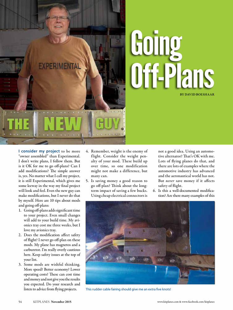
not a good idea. Using an automo-tive alternator? That’s OK with me. Lots of flying planes do that, and there are lots of examples where the automotive industry has advanced and the aeronautical world has not. But never save money if it affects safety of flight.
6. Is this a well-documented modifica-tion? Are there many examples of this
www.kitplanes.com & www.facebook.com/kitplanes54 KITPLANES November 2015
I consider my project to be more “owner assembled” than Experimental. I don’t write plans, I follow them. But is it OK for me to go off-plans? Can I add modifications? The simple answer is, yes. No matter what I call my project, it is still Experimental, which gives me some leeway in the way my final project will look and feel. Even the new guy can make modifications, but I never do that by myself. Here are 10 tips about mods and going off-plans:1. Going off-plans adds significant time
to your project. Even small changes will add to your build time. My avi-onics tray cost me three weeks, but I love my avionics tray.
2. Does the modification affect safety of flight? I never go off-plan on these mods. My plane has magnetos and a carburetor. I’m really overly cautious here. Keep safety issues at the top of your list.
3. Some mods are wishful thinking. More speed? Better economy? Lower operating costs? These can cost time and money and not give you the results you expected. Do your research and listen to advice from flying projects.
4. Remember, weight is the enemy of f light. Consider the weight pen-alty of your mod. These build up over time, so one modification might not make a difference, but many can.
5. Is saving money a good reason to go off-plan? Think about the long-term impact of saving a few bucks. Using cheap electrical connectors is
By DaviD Boeshaar
Going Off-Plans
This rudder cable fairing should give me an extra five knots!

mod flying? This is not really going off-plans, it is just a plans addendum.
7. Is the mod a kit I can buy that many others have already done? My nav lights fall into this category. LED lights for wings and tail that many others have used will be a great update to my plane. It will save a few bucks and a few pounds as well!
8. Be sure you understand the mainte-nance implications of an off-plans modification. Does it need extra work at condition inspection time? Does this mod have a limited service life?
9. Is the modification legal? Just because it’s an Experimental aircraft doesn’t mean you have carte blanche
freedom. Using bolts from the local hardware store or building your own transponder may not get you past inspection. For some mods, getting in touch with a DAR early may be a good idea.
10. If going off-plan involves a new ven-dor, do your homework. Make sure they are going to be around for sup-port. If not, can you support this mod yourself?
Building an Experimental aircraft is possible even if you are not an avia-tion engineer. Thousands have done it! Modifications are a natural part of the process and even expected in certain areas such as avionics. When considering modifications, keep safety as the top factor, then add cost, time to build, performance, and cool-factor after that. J
KITPLANES November 2015 55 Photos: David Boeshaar
DaviD Boeshaar
David Boeshaar is a systems analyst for corporate Disney. A former mechanic, teacher, and computer help desk guru at a major university, he is now build-ing a Van’s RV-9A for fun with his brother-in-law. As the new guy in aviation, Dave has learned lots, both good and expensive, and hopes to pass along a little help to the builders coming up behind him.The parking brake valve is pretty impor-
tant to me, and I’ll add it to the annual condition inspection checklist.
Easy entry and exit.

56 KITPLANES November 2015 www.kitplanes.com & www.facebook.com/kitplanes
maintenance matters
A clean plane is a safer plane and a source of pride.
Cleaning your plane seems like such a simple thing, but that doesn’t mean there aren’t right and wrong ways to do it. Major damage can result from improper cleaning, so let’s take a look at what works and what doesn’t when it comes to keeping your plane looking good.
Cleaning Windows and WindshieldsThe surfaces most often cleaned and most vulnerable to damage are acrylic windows and windshields. Just about every time you fly, you will have occa-sion to clean the windshield. Improper cleaning will reveal itself fairly quickly, but some mistakes may take longer to exact their toll. Window material may go by names such as Lucite or Plexiglas. No matter the name, almost all Experimen-tal aircraft windows and windshields are made of acrylic, so be sure to only use cleaners and polishes approved for use on acrylic, not glass window cleaners.
The best thing to remove dust and loose material on a window is clean water. A gentle spray will wash away most dust and at least a few bugs. Even better is a gentle application of soapy water. Be sure to use gentle soap such as dish soap made for hand washing dishes (not dishwasher or most laundry soaps). Popular products like Dove or Ajax liquid dish soap work well, as does Woolite, a gentle laundry soap favored by the staff at our sister publication, Light Plane Maintenance (LPM). All of these should
be well-diluted in clean water. Do not use any ammonia-based window clean-ers like Windex or household cleaners like 409 or Simple Green. These contain chemicals that can damage acrylic.
Stubborn spots on acrylic surfaces need to be removed gently using your bare hand or nothing harsher than a soft cotton or microfiber cloth. In all cases it is imperative to only use clean implements to wash acrylic surfaces. The priority here is to avoid scratches. Paper towels should never be used on acrylic windows or windshields.
It is best to remove watches and rings before cleaning windows. Even belt buckles or pants rivets can cause trouble if you need to lean over the windshield to clean the opposite side. If this sounds extreme, remember how much work it was to install the windshield the first
time. You don’t really want to do that again, do you?
If you encounter a really stubborn spot that has you thinking about reach-ing for the big guns, in other words strong solvents, take a breath first. The stronger the solvent the more likely it is to do permanent damage. Mineral spir-its can be considered, but beyond that, solvents such as acetone or methyl ethyl ketone (MEK) are very likely to do more harm than good. If it comes to that, it will be better to leave a small spot that won’t yield to your efforts rather than create a larger spot that will permanently mar a window or windshield.
If you are somewhere where you do not have access to soapy water, I’ve had good luck cleaning windshields with a product called Plexus. It is specifically designed for cleaning acrylic windows.
Dave Prizio is a Southern California native who has been plying the skies of the L.A. basin and beyond since 1973. Born into a family of builders, it was only natural that he would make his living as a contractor and spend his leisure time building airplanes. He has so far completed three—a GlaStar, a Glasair Sportsman, and a Texas Sport Cub—and he is helping a friend build a fourth, an RV-8. When he isn’t building something, he likes to share his love of aviation with others by flying Young Eagles or volunteering as an EAA Technical Counselor. He is also a licensed A&P mechanic and a member of the EAA Homebuilt Aircraft Council.
Dave Prizio
Clean your acrylic windows with a product specifically made for the purpose such as Plexus. Use a clean cotton or microfiber cloth. An up-and-down motion is preferred over a circular motion. Remove watches, rings and other things that might scratch your windows.

Spray it on generously and then wipe it off with a clean cotton or microfiber towel. After using the towel once, do not reuse it on a windshield until it has been washed. Wipe with an up-and-down motion, not a circular motion, for best results. Cee Bailey’s Premium Windshield Cleaner or Meguair’s PLASTX also work well. PLASTX is a cleaner and polish, so it is very good on tiny scratches or sur-faces dulled by prolonged exposure to weather. Cee Bailey’s makes windshields for many motorcycles and a number of Experimental airplane kits includ-ing Glasair, Zenith and the RV-10. There may be other cleaners that work just as well, but you should always test any new product before you use it on your plane.
If You Scratch ItScratches can often be removed suc-cessfully if they aren’t too deep and especially if they aren’t in a primary vision area. Aircraft Spruce and other aviation vendors sell kits that take you through several steps of using finer and finer abrasives before finally polishing the scratched spot until it is clear. You can duplicate the contents of the kit if you have a number of wet and dry sand-paper grades from 400 to 2000 grit and then use a polishing compound to fin-ish. The kit is just more convenient for most people. The important thing is to remove the absolute minimum amount of material. If your view is distorted by the repair, you may have no choice but
Photos: Dave Prizio KITPLANES November 2015 57
Extreme Simple Green Aircraft & Precision Cleaner applied full strength is effective at removing bugs and other dirt from leading edges of wings and struts. It is not recommended for use on windshields or other acrylic windows unless diluted. Do not use regular household Simple Green.
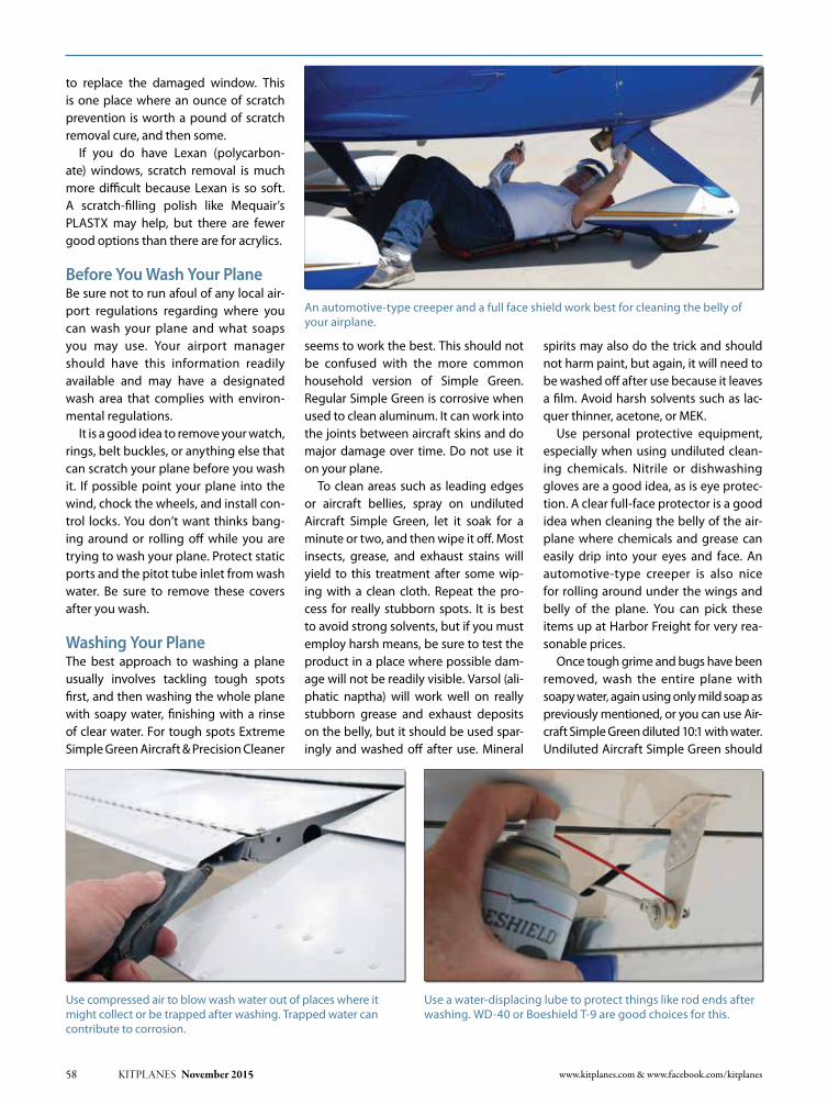
58 KITPLANES November 2015 www.kitplanes.com & www.facebook.com/kitplanes
to replace the damaged window. This is one place where an ounce of scratch prevention is worth a pound of scratch removal cure, and then some.
If you do have Lexan (polycarbon-ate) windows, scratch removal is much more difficult because Lexan is so soft. A scratch-filling polish like Mequair’s PLASTX may help, but there are fewer good options than there are for acrylics.
Before You Wash Your PlaneBe sure not to run afoul of any local air-port regulations regarding where you can wash your plane and what soaps you may use. Your airport manager should have this information readily available and may have a designated wash area that complies with environ-mental regulations.
It is a good idea to remove your watch, rings, belt buckles, or anything else that can scratch your plane before you wash it. If possible point your plane into the wind, chock the wheels, and install con-trol locks. You don’t want thinks bang-ing around or rolling off while you are trying to wash your plane. Protect static ports and the pitot tube inlet from wash water. Be sure to remove these covers after you wash.
Washing Your PlaneThe best approach to washing a plane usually involves tackling tough spots first, and then washing the whole plane with soapy water, finishing with a rinse of clear water. For tough spots Extreme Simple Green Aircraft & Precision Cleaner
seems to work the best. This should not be confused with the more common household version of Simple Green. Regular Simple Green is corrosive when used to clean aluminum. It can work into the joints between aircraft skins and do major damage over time. Do not use it on your plane.
To clean areas such as leading edges or aircraft bellies, spray on undiluted Aircraft Simple Green, let it soak for a minute or two, and then wipe it off. Most insects, grease, and exhaust stains will yield to this treatment after some wip-ing with a clean cloth. Repeat the pro-cess for really stubborn spots. It is best to avoid strong solvents, but if you must employ harsh means, be sure to test the product in a place where possible dam-age will not be readily visible. Varsol (ali-phatic naptha) will work well on really stubborn grease and exhaust deposits on the belly, but it should be used spar-ingly and washed off after use. Mineral
spirits may also do the trick and should not harm paint, but again, it will need to be washed off after use because it leaves a film. Avoid harsh solvents such as lac-quer thinner, acetone, or MEK.
Use personal protective equipment, especially when using undiluted clean-ing chemicals. Nitrile or dishwashing gloves are a good idea, as is eye protec-tion. A clear full-face protector is a good idea when cleaning the belly of the air-plane where chemicals and grease can easily drip into your eyes and face. An automotive-type creeper is also nice for rolling around under the wings and belly of the plane. You can pick these items up at Harbor Freight for very rea-sonable prices.
Once tough grime and bugs have been removed, wash the entire plane with soapy water, again using only mild soap as previously mentioned, or you can use Air-craft Simple Green diluted 10:1 with water. Undiluted Aircraft Simple Green should
Use compressed air to blow wash water out of places where it might collect or be trapped after washing. Trapped water can contribute to corrosion.
Use a water-displacing lube to protect things like rod ends after washing. WD-40 or Boeshield T-9 are good choices for this.
An automotive-type creeper and a full face shield work best for cleaning the belly of your airplane.

KITPLANES November 2015 59
not be used on acrylic surfaces. Pressure washing is not recommended, especially high-pressure washers. They can drive water and cleaning chemicals into seams and joints in aircraft skins and penetrate seals into bearings and actuators. Even a garden hose with a spray nozzle should not be directed straight at bearings, rod ends, or hydraulic actuators. Avoid abra-sive cleaners or strong alkali soaps.
After WashingAfter your plane has been washed and rinsed, dry it thoroughly with a cham-ois or old, clean, bath towels. Use com-pressed air to blow out any trapped water, and be sure to remove any protec-tion from the pitot tube and static ports. A squirt of WD-40 or other water-dis-placing lube can help flush water from exposed rod ends and hinges. Sump your fuel tanks to be sure no wash water got into the fuel system.
Be sure to note any corrosion, loose or missing fasteners, peeling paint, or cracks you may have seen when washing or
drying the plane. This is the best time to look for these things, since the plane will be clean and your attention will be focused on the entire exterior of the air-craft. Anything that needs immediate attention should get it as soon as pos-sible. If you really want to do some good research on aircraft corrosion control, you might want to take a look at FAA advisory circular AC43-4A. It is numbingly long, but at least it is free on the web, and it has some good information in it.
Obviously this is the time to think about waxing your plane if you have the time. As an alternative, it is a good idea to wax the leading edges of the wings, struts, and tail surfaces to make insect removal easier. This minimal application of carnauba-type wax will not take too much time and will make cleaning easier next time. Waxes that contain silicone should generally be avoided, especially if you have a fabric covered airplane. The silicone gets into the fabric and makes it all but impossible to patch it later should the need arise.
If you intend to wax your whole plane, or if you have oxidized paint that needs to be polished out, you will want to invest in a power buffer/polisher. This is where I get on the phone and call the local air-craft detailer, but you can do it yourself if you have the time and energy. Just be sure to get some knowledgeable help the first time you do. This is especially true for those of you with unpainted alu-minum wings, which is really a subject of its own. Polished aluminum can be a beautiful thing, but there are definitely easier and harder ways to do it. Actually, there are just hard and harder ways to do it if we are being perfectly honest. Talk to someone with firsthand experience to get some helpful hints.
Besides having a nice clean plane, there is a real benefit to washing your plane. It gives you the chance to spot cor-rosion and minor cracking that may have escaped your notice on your typical pre-flight inspection. Be on the lookout for these things as you give your prized bird the once over. J
Quarter-inch pilot bits in hole saws have a tendency to enlarge the pilot hole as they cut. The result is an egg-shaped hole because the pilot bit wanders. For-tunately, the solution is simple. 1. Cut a piece of 1/4-inch steel rod. Grind
or file a flat where the set screw will land. The flat keeps the pilot from rotating in the cutter.
2. Cut a piece of plywood or hardwood. Drill a hole and enlarge it to 1/4 inch with a reamer. The reamer leaves a perfectly round hole to the correct dimension. The wood block serves as a sacrificial backing plate and guide.
3. Drill the guide hole in the part and ream to 1/4-inch diameter.
4. Secure the wood block to the drill press with the hole-cutter guide pin per-fectly aligned in the guide hole. If pos-sible, clamp the part to the guide block.
5. Double-check that the holes are aligned with the guide pin.
6. Lube the cutter and guide pin with a good lube like beeswax or Boelube stick.
7. Set the drill press for a slow speed: 250 rpm is a good.
8. Proceed with low pressure and be ready for the cutter to break through. It can hang on the last bit, so back off and take a look. Apply very little pres-sure as it breaks through, or pull the part and cut the last bit by hand with a Dremel and cutoff wheel. J
Eliminating Egg-Shaped Holes
By Larry Larson
SHOPTIPS

60 KITPLANES November 2015 www.kitplanes.com & www.facebook.com/kitplanes
has taught students how to fly in California, Texas, New York, and Florida. She’s towed gliders, flown ultralights, wrestled with aerobatics, and even dabbled in skydiving. She holds an Airline Transport Pilot certificate, multi-engine and single-engine flight instructor ratings, as well as glider and rotor-craft (gyroplane) ratings. She also helped with the build of her Kitfox IV and RV-10.
Amy Laboda
I’m not really sure when we finally decided it was time to update our instru-ment panel. I’m aware that there are a few people out there shaking their heads at the mere mention of a panel upgrade. After all, the airplane received its airwor-thiness certificate in 2008. How out of date could the panel be?
Well, since you asked…We began construction on our Van’s Aircraft RV-10 the winter of 2004 (serial number 250-something). Frankly, I should not have even been thinking of an instru-ment panel at that point, but so much of the reason we were building was cen-tered around the fact that we wanted a modern, sleek, well-instrumented, IFR-capable aircraft. What the instrument
panel could hold, relative to our budget, was key to the whole project.
Turns out it was 2004 when GRT Avion-ics’ Greg Toman developed the Horizon I EFIS for his RV-6A. It was one of the more robust EFIS units on the market, and to be honest, I spent a lot of time hanging around the GRT booth at Sun ’n Fun and AirVenture ogling at the box. It was in our budget. We had experience with the company’s venerable EIS unit, which we had put in our Kitfox IV in 2000, and we liked the way Toman built his products. Robust, hardened, and durable—those are words you like to hear when you are purchasing electronics—especially avi-onics. Toman also offered his databases for the Horizon I units for free. Anyone paying for IFR Garmin GPS database updates knows how much that is worth over the lifetime of any instrument.
It was another two years before we actually purchased any instrumentation for our build, and if I had it to do again, I’d have delayed the purchase for even another year, if I could get away with it. As quickly as avionics are developing and improving, the longer you wait to outfit your instrument panel, the more likely you are to find the coolest, most capable devices to populate its real estate. As it turned out, by the time we got our RV-10 flying, in mid-2008, the Horizon I EFIS that was pretty much the neatest thing I’d seen in 2005 was already looking a little dated. Toman brought out the EFIS HX, with a faster processor, more connec-tivity, and larger, high-definition screens right around that time. Argh!
I was found hanging around the GRT booth once more, ogling this time at the HX boxes. Swapping mine out was, well, possible. But financially really not practical at all. Toman was supporting the Horizon I, and the boxes I had put in my airplane were rock-solid performers. My extremely practical builder/husband/mechanic pointed out that you don’t mess with things that work. OK, he had a point.
Instead of upgrading the panel we swapped XM weather for ADS-B, and added redundancy with a TRW battery backup. These upgrades made sense, both financially and practically.
Taking our instrument panel into the next decade.
First-generation GRT Horizon I EFIS units were extremely capable.
New HX EFIS units are amazingly quick and sharp compared to first-generation boxes.

KITPLANES November 2015 61
Fast forward nearly 1000 flight hours of uninterrupted, solid performance. One day in early 2015, GRT Avionics offered to buy back the Horizon I boxes if we’d upgrade to the company’s modern HX or HXr product line. The numbers weren’t bad, either. Best of all, we could keep the dual AHRS and magnetometers and reuse them with the new EFIS. The HXr box, with its remote-mounted radios and 10.4-inch screen made no sense for our panel, but, after measuring, it appeared that two 6.5-inch HX screens would fit, snuggly, in the basic footprint of the old Horizon I boxes. We blinked.
Strategic InstallA few weeks later a box arrived from GRT. Why only one? It was prime flying season in our neck of the woods, and we really did not want to lose the use of the air-plane for any significant length of time. For that reason we opted to upgrade the screens one at a time. It also gave us the ability to fly with our well-known Hori-zon I right next to the new HX, so that we could learn the new, all the while having the security of the old right there, just in case. (Turns out that manipulating the HX is so much like the Horizon I that this was really not a problem.)
Measure Twice, Cut OncePerhaps the most daunting part of the whole upgrade came at the very begin-ning—figuring out how to make the two HX boxes fit into the panel. Metal had to be removed. We did not want to pull the whole panel out; that would have had the airplane down for a considerable time. So my builder devised a method for removing the metal very carefully. He created a metal catchment system for
any scrap material, to keep it from con-taminating the area behind the panel. Wiring was carefully bundled and tucked back and a plastic drop cloth sealed to the backside of the panel.
He then chose his tools thoughtfully. Ultimately he settled on a drill and saw technique that, though slower, was less likely to spray very fine metal dust into the area behind the panel, the way a rotary saw might have done. (That dust is nearly impossible to completely remove, and can cause random shorts in your avi-onics that will drive you insane as you try to chase them down at a later date.)
Not Exactly Plug-n-PlaySo, what exactly did it take once the panel was cut and the HX turned up on our doorstep? Less—and more—than we thought. GRT Avionics techs tell their customers right up front that these EFIS boxes are not really designed to be plug-n-play. Rather, they are designed to afford the user tremendous flexibility and capability. The HX sports a power-ful processor, plethora of connection options, more software settings than I think even the techie-ist of techies will ever need (someone will refute that statement, I’m sure), and compatibility with a wide range of avionics and acces-sories from different manufacturers.
There are serial, Ethernet, USB, ARINC 429 ports, and more on the HX. With optional bluetooth connectivity, I can even use my Android smartphone to pre-plan flights and then upload them to the HX once I’m at the airplane. Want to set the radios or change that plan in flight? I can do that, too, with my smart-phone. Not that I will (although the idea that I can do it without reaching
over into the “captain’s” space is kinda fun to contemplate). There are so many choices for connecting and configur-ing the boxes (above what the Horizon I offered) that it may very well have been the most daunting part of the entire ret-rofit. Of course, to get that functionality you’ve got to set up the boxes. Deciding how to maximize the connectivity took hours of planning, combined with sev-eral calls to GRT techs for advice.
If you are considering installing GRT products in your panel, you need to be the kind of builder who doesn’t just read the install/user manuals—you need to digest them. The good news is that GRT techs are knowledgeable, capable and, the Holy Grail, available. Hallelujah.
Redundancy, Redundancy, and now, RedundancyOurs is a dual-screen setup, stacked, and it was designed for redundancy. We were nearly redundant with the Horizon I stack, but the boxes lacked enough ports to allow us complete redundancy. This was not a problem with the HX EFIS. Displays one and two are now directly linked via Ethernet. They are also each connected to both AHRS 1 and AHRS 2. That makes them dual-connected to the pitot-static system and magnetometers because each AHRS is connected to its respective magnetometer (see the diagram).
Photos: Amy Laboda
Measure twice, cut once. Special attention was paid to capturing all the scrap metal.
Display Unit
AHRS
GPS
EIS
Serial Port 3 4800 Baud RatePitot/Static System
Magnetometer
9600 Baud RateSerial Port 4
Modular components of the HX EFIS provide many paths to a redundant system. However, it’s up to the panel designer to ensure the electrons flow properly for ideal functionality.

Our AHRS units are separate; a dual-in-one-box system would defeat the plan. We have a dedicated avionics bay behind the baggage compartment in our airplane where you’ll find the AHRS mounted level with the lateral and lon-gitudinal axes of the aircraft, their con-nectors facing aft, as per GRT specs. Large wiring conduits run beneath the floorboards and seats from the instru-ment panel aft. Our magnetometers have their own shelf in the avionics bay, safely set some two feet from anything that could generate magnetism, includ-ing current carrying wiring. The entire system is set up so that if a component fails, we can pull it out, box it up, and send it to GRT, and then keep on flying if we need to. The repaired or replace-ment component can catch up with us at the next destination.
Flying the Boxes— Was it Worth It?Do you remember when you upgraded from an Intel Pentium CPU to the Core
Duo or Quad-Core chip? Going from 2004 to 2014 technology in your avion-ics is a lot like that. The HX screens boot quickly and their animations and motion are smooth like butter. But even with all that, GRT Avionics has wisely kept the basic functionality of the soft buttons and knobs intact. I was worried that I’d need to learn a whole new EFIS software, but I did not.
There are, however, a few new tricks on the HX. The addition of terrain that is more map-like is welcome. I can even choose to depict actual sectional or en-route charts (for a database fee). Even geo-located approach charting is available if I want it. I don’t, right now. I have all that on my iPad for the moment. I also feel that weather and traffic show up better on the default terrain. It is a personal preference, and yours may differ from mine. I do find the HX’s high-definition screens, which are an inch or so larger than the Horizon I screens, are easier on my eyes.
Functionality aside, I love the new look of the panel. When we took to
the air for the first time with the beast in 2008, we were thrilled to be in our hand-built, modern, general aviation cruiser. It’s satisfying to see it seven years later, all decked out with truly redundant high-definition EFIS units and know that it’s still a modern GA cruiser, and still all we ever wanted in a cross-country airplane. J
62 KITPLANES November 2015 www.kitplanes.com & www.facebook.com/kitplanes
Kitplanes subscriber alert!several of our Kitplanes subscribers have received what appear to be “renewal notices” or “automatic renewal notices” from a company known as preMier subscriptiOn serVice, 5star subscriptiOns, rapiD MaGaZine cOllectiOn, MaGaZine billinG serVices, publisHer’s billinG serVices, circulatiOn billinG center or other
similar names. Addresses for these firms include Dallas, tX; lincoln, ne; Omaha, ne; san luis Obispo, ca; salt lake city, ut; White city, Or and prescott, Fl.
These firms have nOt been authorized by us to sell subscriptions or renewals for Kitplanes and we cannOt Guarantee that any order or payment sent to them will be forwarded to us.
Kitplanes does nOt offer a subscription term of more than 2 years, nor do we retain your bank account information. if you see an offer for 3 or more years or if you receive a notice that references your subscription anD your banking information, it is nOt an authorized offer. We urge you to report these notices to us, as well as to your state’s attorney General and better business bureau. any offer you receive that does not bear our
company logo or corporate/customer service address or 800 numbers should not be considered approved by us.
the only autHOriZeD inFOrMatiOn for Kitplanes is:toll free via telephone 1-800-622-1065, Dial america renewal telemarketing, or www.kitplanes.com/cs
Our texas customer service center: 1-800-622-1065, pO box 8535, big sandy tX 75755
Or our corporate offices at:belvoir Media Group, llc.
aviation publishing Group535 connecticut ave norwalk ct 06854
should you have any questions at all about mail that you receive, please contact us at our web site: www.kitplanes.com/cs or call us toll free to speak to customer service.
Tools used for slow, methodical trimming. Scrap metal was cleared as we went.

Photos and illustration: Bob Hadley KITPLANES November 2015 63
Bob Hadley is the R&D manager for a California-based consumer products company. He holds a Sport Pilot certificate and a Light-Sport Repairman certificate with inspection authorization for his Jabiru J250-SP. Bob Hadley
Bore gauging. There are a number of techniques and tools for measuring inside diameters (IDs). The quickest and easiest is a caliper. While great for “instant” read capability, cali-pers have a few inherent limitations: They can’t reach into a hole beyond the length of their jaws, and the handle can get in the way when trying to measure a bore that is obstructed by its position (for more about calipers, see “Meet Mike and Cal,” Home Shop Machinist, September 2015).
Examples of projects that might require bore gauging include: precision fitting a bearing, making holes for a force-fit, and sizing a bushing block for a control rod. Engine inspection is another application that requires accurate measuring. Bore gauges are used to check bearing journals and connecting rod ends to determine in- or out-of-tolerance condition; and cyl-inders for wear, taper, and out-of-round.
I’ve broken bore gauging into two basic categories: small hole gauges (up to ½ inch) with spherical ends, and large hole gauges (over ½ inch) with telescop-ing ends.
Small Hole GaugingTo measure small holes—up to ½-inch—use a small-bore gauge. These typi-cally come in sets with each unit being adjustable to cover a particular range in the set. A split sphere on the gaug-ing end expands as you twist the handle. You insert the gauge into the hole and adjust the thumbscrew until the sphere barely touches the ID. You extract the gauge and measure it with a micrometer. This type of gauging is
called “transfer measuring” or “transfer gauging” because you’re measuring the gauge and not the hole.
Large Hole GaugingTelescoping bore gauges work on the same principle as the small-hole gauges:
expand, lock, extract, and measure. The plungers are spring loaded, so all you have to do is hold the gauge exactly per-pendicular to the bore axis and tighten the handle to lock it. Any slight devia-tion from exactly perpendicular will yield an oversize reading. It’s a good idea to
Home Shop Machinist
This imported four-piece small-hole gauge set (covering a range from 1/8 inch to ½ inch) costs about $35. You could spend $100 or more for a premium brand like Brown & Sharpe or Starrett, but the import set is more than adequate for the home shop.
To gauge a small hole, adjust the thumb-screw on the handle until the sphere just barely touches the inside diameter. Extract and measure the sphere to determine the hole size.
The telescoping bore gauge must be square and perpendicular to the hole to obtain an accurate measurement.

64 KITPLANES November 2015 www.kitplanes.com & www.facebook.com/kitplanes
gauge the same spot a few times until you get a consistent result.
Telescoping gauges can be very accurate, but it takes some practice to get the feel for them. They can be a bit tedious if you have to check or com-pare a lot of holes. Still, for the home shop, they are a good option because they are inexpensive.
Dial-Type Bore GaugeA step up from the telescoping gauge is the dial-type bore gauge. Like the small-bore and telescoping gauges, the dial bore gauge is, despite the presence of an indicator, a transfer gauge. The indicator display (either a mechanical pointer or digital readout) does not provide a direct reading of the bore diameter. The pur-pose of the indicator is to make it easier to dial-in “zero” when gauging a bore. The device is basically a fancy telescop-ing gauge with the indicator showing the plunger movement.
To use a dial bore gauge, you select an extension probe that is within the range of the hole to be measured. The probe threads onto a plunger head that articulates the dial indicator. Insert the gauge into the hole and observe the dial. As you (gently) rock or tilt the probe off perpendicular, the indicator will oscillate between some minimum and maximum reading. The minimum read-ing is where the gauge is perpendicular and correct for measuring a bore. At this point you turn the dial bezel to line up “zero” to the needle (or press “zero” if using a digital gauge). It may take a few tries to correctly zero the needle; get it in the ballpark, re-gauge the bore and reset the dial as needed until you get zero every time.
To obtain the bore diameter, mea-sure between the extension probe and plunger with a micrometer. Carefully adjust the mike until the indicator on the bore gauge reads close to zero. The
correct reading is obtained when, as you rock the bore gauge between the mike anvils, the needle “zeros out,” just like it did in the bore. The reading on the mike is the bore ID. It can be a bit awkward to mike a bore gauge. Some people prefer to clamp the micrometer in a stand.
For most work, a dial bore gauge is not quicker nor more accurate than a tele-scoping gauge. Where a dial bore gauge really shines is when checking or com-paring a number of cylinders or checking for taper. Once you set zero, you can use the direct reading on the dial to compare for over-size or under-size variances, or check the taper of a cylinder.
ConclusionStepping up from a caliper to a set of dedicated bore gauges is part of the natural progression of the home shop machinist. A basic set of small-bore gauges and a range of telescoping gauges will meet the needs of most
A dial-type bore gauge. This set will gauge holes from 18mm to 33mm with the supplied probes. Prices for a dial bore gauge set like this: between $70 and $200.
The business end of the dial bore gauge.
Telescoping bore gauges come in a variety of sizes. The set on the left covers a range from ½ inch to 11/4 inches and costs $35. The set above covers ½ inch to 6 inches and costs $45.

KITPLANES November 2015 65
projects you might encounter. The aver-age home machinist can, with practice, achieve respectable precision.
The tools are relatively inexpensive, the techniques relatively simple, and the results are pretty accurate. All in all, ideal for the home shop! J
Using the dial bore gauge.

66 KITPLANES November 2015 www.kitplanes.com & www.facebook.com/kitplanes
Bob Cartwright’s RV-7RV-7 N646RC (builder # 71194) flew for the first time on the morning of October 4, 2011 after eight years of construction with Jerry Ronk at the controls. All went well except for a yaw trim issue.
The plane is equipped with a Mattituck/ECI TMX O-360, Whirl Wind RV-200 prop, Dynon D-100/D120, iFly 720 GPS, Garmin SL-40 com, Garmin GX-327 transponder, TruTrak DigiFlight IIVS autopilot. It flew for 18 months to work out all issues prior to paint. The empty weight after paint is 1073 pounds.
I would like to thank Jerry Ronk, Mike Howard, TW (Tom Wieduwilt), Ron Wood, Kevin Faris, Jerry Mason, Jim Gallamore, and anyone else I forgot in EAA Chapter 80, and of course, my wife Carolyn (she actually bucked a few rivets before she decided it was too hard), for support and advice for the last eight years.
Omaha, [email protected]
Dale Williams’ “myunn” Corvair-powered Sonex“Myunn” (N319WF), a Corvair powered Sonex airframe, was purchased from a previous owner who had begun the fuselage and intended to use an AeroVee VW conversion engine. The kit came with factory-assembled wingspars. Following the purchase in January, 2010, my building mentor, Dick Fisher, and I began the reconstruction process after much disassem-bly because of changes we wanted to make and poor workmanship that was found. We installed the 3.0 120-hp Corvair conversion that was built for us by Dan Weseman of SPA (http://flywithspa.com) using his custom
motor mount and nose bowl for the cowling assembly. The engine is built to William Wynn specifications (http://flycorvair.net) and utilizes his gold oil filter system and prop hub. It is equipped with an oil-fed BTA 5th bearing for prop loads and a Sensenich 54x58 propeller.
The interior is from the factory, and the instruments are MGL. We included an LRI (lift reserve indicator), along with a Flightline FL-760 radio and iFly 720 GPS.
First flight was in August 2012. Flight characteristics were excellent, and the Corvair power was smooth and abundant.Signature Finish (www.signaturefinish.com) paint was applied using Tom Fabula’s roll-on method, which added 20 pounds.
[email protected]://WEBSitES.ExpERCRaft.COm/DalEaNDEE
herbert telge’s Van’s RV-12After almost a year of work, we completed our Vans RV-12 kit in January 2014. This was a team effort (dad and son project) done in Lima, Peru. Our plane is flying very well with approximately 25 hours in April 2014.
In the picture you can see our RV-12 and Herbert senior and Herbert junior at our local ultralight club located 40 miles south of Lima (San Bartolo).
lima, pERu [email protected]
Dick harriman’s WaiexMy Waiex was started on October 1, 2012 and completed 10 months later with 1350 man-hours of work. My building and flying partner, Mike Tabler, and I are both retired pilots of the 55th wing, 343 squadron, and the aircraft is painted in the colors of the 343rd, 55th Fighter Group of WW-II (P-51). The aircraft flies great and is powered by the AeroVee engine. Sonex has been great in working out any hiccups we have had along the way.
papillON, [email protected]

KITPLANES November 2015 67
Submissions to “Completions” should include a description (250 words maximum) of the project and the finished aircraft. Also include a digital image of the aircraft. Minimum digital image size is 1500 pixels wide x 900 pixels high (5 x 3 print size at 300 dpi). Please include a daytime phone number where we can contact you if necessary. Also indicate whether we may publish your address in case other builders would like to contact you. Email text and photos to [email protected] with a subject line of “Completions.” You may also submit electronically at www.kitplanes.com, just click on “Completions: Add Yours” in the upper right corner of the home page.
Norton and Booher twin ZenithsN750MN took to the sky on September 10, 2013 for her maiden voyage. N750HB followed on Septem-ber 11, 2013. Mike Norton and Dick Booher, friends for 40 years, decided to build a pair of identical air-planes. We spent just over 14 months building the two planes.
Both are powered by the ULPower 350iS 130-hp fuel-injected FADEC engine. Engine monitoring and flight instruments are provided by the Dynon FlightDEK-D180. Other equipment includes a BendixKing GPS, Icom A210 com and Garmin GTX 327 transponder. We also mounted an ADS-B receiver in the glove box for weather and traffic being sent via Bluetooth to the RAM-mounted iPad on the panel. The props are a new design, a composite three-blade by Craig Catto, along with a spun aluminum spinner made by Allan Cummins in Australia.
We built the planes at home and transported them to the airport for final reassembly. This was the first build for each of us, and we frequently assisted each other during various stages. I could not have completed my plane without Dick’s assistance, and I am confident he feels I helped him occasionally.
We both have to thank our loving wives for their support and understanding during construction. Kudos goes to Zenith Air-craft for creating the simple kit, as well as the endless factory support provided by Sebastien Heintz, Caleb Gebhardt, Roger Dub-bert, Shirley Swearingen, Joyce Fort, and Linda Wolf.
ViNE gROVE, [email protected]
thomas Vanderheyden’s RV-7After contemplating building an airplane for 20 years, I began my RV-7 project in June 2009, and the first flight was in October 2012, after a total build time of about 2,500 hours. The engine and prop are the standard Van’s combination of the IO-360-M1B and Hartzell propeller. The panel was by Aerotronics, with a Dynon SkyView and a Garmin 530W.
Ray Sievers’ Van’s aircraft RV-9After nine years and 3500+ hours of effort, S/N 91219 took its first flight on November 27, 2013. What a wonderful kit and outstanding factory sup-port from those people in Aurora, Oregon. It flew wonderfully on the first flight, in trim, and it really climbs. This is a slow-build standard kit, and I rebuilt the O-320-E2A out of a Cherokee myself after attending the dis-assembly/assembly class at Lycoming (thank you, Jim Doebler). It swings a Catto 70-inch diameter x 68-inch pitch propeller.
My eternal gratitude for all the wonderful instructors at the many build-er’s classes that I attended, and my EAA tech counselor Bill Tromblay. Thanks also to local avionics guru, Bernard Thalman, and finally, to my tireless helpers, David Harrison and Carlos Rivera.
KENOSha, [email protected]
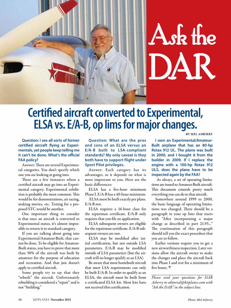
68 KITPLANES November 2015 Photo: Mel Asberry
Please send your questions for DAR Asberry to [email protected] with “Ask the DAR” in the subject line.
Question: I see all sorts of former certified aircraft flying as Experi-mentals, yet people keep telling me it can’t be done. What’s the official FAA policy?
Answer: There are several Experimen-tal categories. You don’t specify which one you are looking at going into.
There are a few instances where a certified aircraft may go into an Experi-mental category. Experimental exhibi-tion is probably the most common. This would be for demonstrations, air racing, making movies, etc. Testing for a pro-posed STC would be another.
One important thing to consider is that once an aircraft is converted to Experimental status, it’s almost impos-sible to return it to standard category.
If you are talking about going into Experimental/Amateur-Built, that can-not be done. To be eligible for Amateur-Built status, you have to prove that more than 50% of the aircraft was built by amateurs for the purpose of education and recreation. And that just doesn’t apply to certified aircraft.
Some people try to say that they “rebuilt” the aircraft. Unfortunately rebuilding is considered a “repair” and is not “building.”
Question: What are the pros and cons of an ELSA versus an E/A-B built to LSA-compliant standards? My only caveat is they both have to support flight under Sport Pilot privileges.
Answer: Each category has its advantages, so it depends on what is most important to you. Here are the basic differences:
ELSA has a five-hour minimum Phase I. E/A-B has a 40-hour minimum.
ELSA must be built exactly per plans. E/A-B not.
ELSA requires a 16-hour class for the repairman certificate. E/A-B only requires that you file an application.
ELSA subsequent owners are eligible for the repairman certificate. E/A-B sub-sequent owners are not.
ELSA may be modified after ini-tial certification, but not outside LSA parameters. E/A-B may be modified outside of LSA parameters (but the air-craft will no longer qualify as an LSA).
Be aware that most homebuilt aircraft that meet LSA requirements can only be built E/A-B. In order to qualify as an ELSA, the aircraft must be built from a certificated ELSA kit. Most kits have not received this certification.
I own an Experimental/Amateur-Built airplane that has an 80-hp Rotax 912 UL. The plane was built in 2000, and I bought it from the builder in 2009. If I replace the engine with a 100-hp Rotax 912 ULS, does the plane have to be inspected again by the FAA?
As always, a set of operating limita-tions are issued to Amateur-Built aircraft. This document controls pretty much everything you can do to that aircraft.
Somewhere around 1999 to 2000, the basic language of operating limita-tions was changed. There should be a paragraph in your op lims that starts with “After incorporating a major change as described in part 21.93...” The continuation of this paragraph should tell you the exact procedure that you are to follow.
Earlier versions require you to get a new airworthiness inspection. Later ver-sions allow the aircraft owner to make the changes and place the aircraft back into Phase I and test for a minimum of five hours. J
Certified aircraft converted to Experimental, ELSA vs. E/A-B, op lims for major changes.
By Mel AsBerry

KITPLANES November 2015 69
Aircraft Spruce & Specialty CV4 877-4SPRUCE
Aircraft Tool Supply Co. 57 800-248-0638
Avemco Insurance Company 13 888-241-7890
Beringer 57 708-667-7890
Better Aircraft Fabric 57 907-229-6792
California Power Systems 55 800-AIRWOLF
CubCrafters 3 509-248-9491
Dynon Avionics CV2 425-402-0433
Garmin International 5 913-397-8200
Garmin International 39 913-397-8200
Grand Rapids Technologies 25 616-245-7700
Grand Rapids Technologies 33 616-245-7700
Ivoprop 65 800-FOR PROP
Kitfox Aircraft 13 208-337-5111
KITPLAnES® Bookstore 43 800-780-4115
Lancair 43 541-923-2244
Progressive Aerodyne 65 855-732-7395
Sonex Aircraft, LLC 55 920-231-8297
Stewart Systems 65 888-356-3490
Van’s Aircraft 9 503-678-6545
Zenith Aircraft Co. CV3 573-581-9000
Builders’ Marketplace
Aerotrek Aircraft 72 812-384-4972
Airflow Performance 73 864-576-4512
Bearhawk Aircraft 72 877-528-4776
Bede Corp. 72 See Advertisement
Better Half VW 71 281-383-0113
Carlson Aircraft 71 330-426-3934
Falconar Avia Inc 73 780-465-2024
Flight Data Systems 70 831-325-3131
Flight Grip 71 800-204-7625
Glen-L 71 888-700-5007
Grove Aircraft 71 619-562-1268
Homebuilt Help 72 See Advertisement
InFInITY Aerospace 73 See Advertisement
Innovator Technologies 70 403-669-3101
Kuntzleman Electronics Inc. 71 610-326-9068
Matco Manufacturing 72 801-335-0582
Mountain High Equipment 72 800-468-8185
Mustang Aeronautics 70 248-649-6818
Osprey Aircraft 70 See Advertisement
Recreational Power Engineering 72 800-583-3306
Sportsman’s Market 70 800-SPORTYS
TCW Technologies 73 See Advertisement
Tormach LLC 73 See Advertisement
WhirlWind Propellers 71 619-562-3725
Zenair Ltd. 71 705-526-2871
advertiser page # telephone advertiser page # telephone
List of AdvertisersPlease tell them you saw their ad in KITPLANES® Magazine.
KITPLANES® interactive makes it quick and easy for you to receive instant information about products or services directly from our advertisers’ web sites.
➥ Go to: www.kitplanes.com/links for a virtual shopping tour via links to their web sites.
➥ Call the phone numbers listed below and be sure to tell them you saw their ad in KITPLANES® Magazine.
❏October 2015 Carbon Cub EX-2, Taming the Lancair, Flying Other People’s Planes, Glass Panel Upgrade
❏September 2015 Ten Years With a Time Machine, Becoming a Test Pilot, Family Affair, The Motivated Builder
❏August 2015 SubSonex, 1909 Blériot XI, Carving Fiberglass, Fully Inverted Pocket System, Aircraft Wiring
❏July 2015 Searey LSX, The First Grand Champion, Wicks Aircraft Supply, APP in the Real World
❏June 2015 Turbine-Powered RV-10, Bearhawk Factory, Crewing at Reno, Legalities of Fly-Ins
❏May 2015 Groppo Trail Kit, KR Fly-In, Formula 1, Vinyl Graphics, Easier Panel Wiring, Camera Mounts
❏April 2015 Arion Lightning XS, STOL Mods, Fred to Florida, Bootstrap Testing, PS Engineering PDA360EX
❏March 2015 Wag-A-Bond, Meredith Effect, Buying a Used Experimental, Communications, The new Guy
❏February 2015 2015 Engine Buyer’s Guide, Backcountry Fox, Sonex T-Flight Program, Deciding What to Build
❏January 2015 Mojave Gang Mo’Venture, Single-Seat Hot-Air Balloon, One Week Wonder, Vetterman Exhaust
BACK ISSUESONEW eBOOK O
eBook download is exactly the same magazine as on the newsstand.
The difference is:
you get it now! &
no shipping costs for e-books!
(a big savings for our international customers)
eBooks download as a single, full size, full color .pdf document which you can view on your desktop, laptop or tablet computer.
PDF eMagazine issues are fully searchable and are compatible with all Adobe Acrobat functions such as highlighting, page notes
and spoken word audio.
O Individual monthly issues are $6.95
O A compiled Aircraft Buyer’s Guide is $12.95
Visit:
www.kitplanesbooks.com
to order
70 KITPLANES November 2015 www.kitplanes.com & www.facebook.com/kitplanes
buiLders’ mArketpLAce
“OSPREY 2” AMPHIBIAN
2-Place, all wood, 12 sec. water take-off, full builder support, Oshkosh award winner. Info Pak $14 ($17 overseas), Plans $250 ($290 overseas).
OSPREY AIRCRAFT3741 El Ricon Way, Sacramento, CA 95864
Email: [email protected]
Follow us on Facebook at www.facebook.com/kitplanes
Share Your Enthusiasm for

KITPLANES November 2015 71
Highlights: • Revamped and expanded Aircraft Buyer’s Guide for quicker, better search results • All New Classifi ed Ads section for deals on aircraft and accessories • Unlimited access to back issues as an easy- to-use, tablet-friendly downloadable PDFIt’s easy to register. Just visit WWW.KITPLANES.COM and click on GET WEB ACCESS.
Have You Seen Us Lately?
The KITPLANES® web site is now better than ever!KITPLANES.COM is YOUR guide to the most comprehensive homebuilt information available, and access to our archives and aircraft database are FREE to registered subscribers!
®
“Like” us on Facebook, follow us on Twitter and get an RSS feed from our Newsline
Get the latest. Follow us on Twitter at #Kitplanes.
Can’t Get Enough
?
www.groveaircraft.com1800 Joe Crosson Dr.
El Cajon, CA 92020619.562.1268Aircraft Landing Gear Systems Inc.
Grove
LANDING GEAR
Factory Direct
Your Complete Source for Wheels, Brakes
& Landing Gear
619-562-3725
• ROTAX
• JABIRU
• CONTINENTAL
• LYCOMING
GROUND ADJUSTABLECOMPOSITE PROPELLERS
www.whirlwindpropellers.com
CUSTOMIZE OUR GRIP FOR YOUR AIRCRAFT
Easy Installation
Comfortable
Rocker (shown) or push button trigger style
Thumb Switches:Push Button, Toggleand/or 4-Way Trim
Fit to 5/8" thru 1-1/8" sticks
Next day shipping for virtually any confi guration you desire.
push button trigger style
sticks
Next day shipping for virtually any confi guration you desire.
812 Jacquelyn St. • Milton-Freewater, Oregon 97862800-204-7625 • 541-938-0533 • Fax: 541-938-7242
ZENAIR FLOATS – EIGHT SIZES!
Kits or factory assembled. 750 to 2500 lbs. MTOM, straight or amphibious, starting at $2,450.00. Aluminum, light, tough,
excellent performances. WWW.ZENAIRFLOATS.COM
or 705-526-2871
SPARS, STREAMLINE STRUTS, RIBS 6061T6 - EXTRUDED - CERTIFIED ANALYSIS
SPARS - 6 sections - 3” to 6 5/8” STRUTS - Large, Small, Heavy Duty, Jury
RIBS - Stc’d, Experimental, Custom Write/Call for free info:
CARLSON AIRCRAFT INC.330-426-3934 • [email protected]
www.carlsonaircraft.com
LEGAL EAGLE ULTRALIGHT
A part 103 legal Ultralight with the popular Better Half VW.$2,000-$5,000 depending on scrounging ability. Kits being
shipped. Plans $50, eng. plans $20, videos $25 ea., prop hubs, info $5 (eng. or plane). Check/m.o.:
L.E. MILHOLLANDPO Box 747-K, Brookshire, TX 77423
Ph: 281-375-5453 • Cell: 281-785-3777Email: [email protected] • www.betterhalfvw.com

72 KITPLANES November 2015 www.kitplanes.com & www.facebook.com/kitplanes
buiLders’ mArketpLAce continued
HIRTH AIRCRAFT ENGINES 15 thru 110 hp. 1000 hour rated TBO. One year warranty. Sales, service, and parts. Highest power to weight ratio in the industry. BlueMax 2-cycle aviation oil. Contact:
RECREATIONAL POWER ENGINEERING5479 East County Rd. 38, Tiffin, Ohio 44883 Tel: 800-583-3306 • Fax: 419-585-6004. Visit us on the web at www.recpower.com
Follow us on Facebook at www.facebook.com/kitplanes
Share Your Enthusiasm for

KITPLANES November 2015 73
Buy a Plane or Sell a
Plane with a FREE ad online.
Any individual may post a flying homebuilt
or partial project complete with photos at no cost for quick
global response. www.kitplanes.com/classifieds
The must-read for the
GA Community!
Log-in for
FREE News Alertswww.avweb.com/kit
111 Airflow DriveSpartanburg, SC 29306(864) 576-4512(864) 576-0201 (Fax)www.airflowperformance.comEmail: [email protected]
Aircraft Multi-point Fuel Injection• Operates all engines from 65 to 800 HP• Applications for V6/V8 engines• Manual Mixture Control• Bolt on Kits for Lycoming Engines• No Carburetor heat required• Instant throttle response• All Mechanical, No Electronics• Increases mid-range HP• Approved for Aerobatic use• Compatible with all Fuels• Precise Fuel Metering under all conditions
1204-8 Airflow 1/10/05 2:35 PM Page 1
2/3 Mustang
and 10 other all wood designs
F12 Cruiser
PLANS - KITS - PARTS
Info Packs $10/ea + $3 Postage HIPEC Covering System - no ribstitching, no taping.
Lo cost — Lo labor — proven
www.falconaravia.comEmail: [email protected]
FALCONAR AVIA INC. Ph: 780-465-2024

74 KITPLANES November 2015 www.kitplanes.com & www.facebook.com/kitplanes
builders’ marketplace
The Builders’ Marketplace offers several advertising opportunities designed to enhance response for your precious advertising dollars. This section offers 1-, 2- or 3-inch ads designed by us or provided by you. Here are samples of the three different sizes, acceptable formats and the rates to submit your own Builders’ Marketplace ad or have us create one using your photo/logo and text.
As you know, advertising isn’t just reaching people...it’s reaching those who are most likely to buy your product and producing results. The kit manufacturers and our regular advertisers who sell via mail order and track their response tell us that KITPLANES® regularly outperforms other media on a cost-per-sale basis. This no-waste circulation delivers greater efficiency for your valuable ad dollars. In advertising, consistency pays off. Your ability to sustain a long-term advertising program shows customers that you’re a successful, reliable brand.
KITPLANES® Marketplace Rates – GROSS effective 10/9/2013
Size 1x 6x 12x
1" 4-color 180 160 130
2" 4-color 400 360 300
3" 4-color 560 510 440
Gross rates include a new ad design with photo and copy to be provided by the advertiser. A 15% discount is allowed for providing the ad to meet our specifications below.
Required File Formats: PDF/X-1a: PDF version 1.3 (Acrobat 4); output resolution 2400 dpi; composite CMYK; high-quality JPEG or lossless Zip compression; resolution for color and gray scale images is 300 dpi; resolution for monochrome images is 1200 dpi; and fonts are embedded and subsetted 100% as well as other characteristics. This format is acceptable for spread, full or partial pages. Trapping is the responsibility of the file provider. Total density should not exceed 300%.
Unacceptable file formats: Other file types, such as Postscript, TIFF, TIFF/IT, EPS or native applications such as Quark, InDesign, Illustrator, Photoshop, etc.
Ink Specifications: 4/C process.
Please visit www.kitplanes.com/advertising to peruse our 2015 Editorial Planner with deadlines to formulate your advertising schedule now, or call Chuck Preston at (805) 382-3363.
Sample 1" Ad– 2.25" wide x 1" high
Sample 2" Ad– 2.25" wide x 2" high
Sample 3" Ad– 2.25" wide x 3" high
Stay up to date. Follow us on Facebook at www.facebook.com/kitplanes
Builders’ Marketplace reaches tens of thousands of homebuilders
and pilots who are eager to buy new products and services.
Share Your Enthusiasm for
Get the latest. Follow us on Twitter at #Kitplanes.
Can’t Get Enough
?
Call 805-382-3363 or email: [email protected]
Working With a tight Budget?
YOUR HOMEBUILT AIRCRAFT AUTHORITY

Photo: James Emery KITPLANES November 2015 75
is a principal aerodynamics engineer for Northrop Grumman’s Advanced Design organization. A private pilot with single engine and glider ratings, Barnaby has been involved in the design of unconventional airplanes including canards, joined wings, flying wings, and some too strange to fall into any known category.
Barnaby Wainfan
Stiffness.Last month, we took a look at some of the problems that can arise when a builder modifies the structure of an air-plane in an attempt to make it stronger. We now continue on the same theme with another subject that can have large structural effects—stiffness.
In addition to the strength of a structure, which is its ability to carry load without failing, we must also be conscious of the stiffness of the structure. It’s a common error to confuse stiffness and strength. Strength determines how much load the element can carry before it fails. Stiffness determines how much a structural ele-ment will deflect under a given load.
It’s easy to think of a very stiff item as very strong. If you pick something up and apply load to it, and it does not bend or twist very much, it seems strong. Unfor-tunately, the small deflection under the loads you can exert tells you nothing of the amount of load that will cause the structure to fail.
Modifications that change the stiff-ness of a structure change the way the loads are distributed into the elements that make up the structure.
Load and DeflectionAll structural elements act like springs; they deflect when loaded. The higher the load on the structure, the greater the deflection.
When the stress in the material is below the critical yield stress, the mem-ber behaves approximately linearly. The deflection is proportional to the load, and the load absorbed by the member is proportional to its deflection. The stiffer
the member, the more load it takes to deflect it a given amount. For an airplane structure, our primary concern is its behavior in this linear range. If the stress exceeds the maximum stress for this lin-ear behavior, the structure will yield and take on a permanent bend if it is made of ductile material like metal, or fail if it is made of more brittle materials like wood or composites.
Load Sharing Stiff parts of a structure tend to carry most of the load because the less-stiff
portions of the structure must deflect much farther before they begin to carry a significant load. An extreme example of this might be the skin on a fabric-covered airplane. When the wing bends, the fabric, which is relatively elastic, will stretch, and carry very little of the bending loads. The spars, which are much stiffer than the fabric, absorb the entire load.
When two structural members are attached together, the deflection of the two members at the point of attach-ment must always be equal or the two
German bureaucrats decided the rear spar of the Fokker D-VIII looked flimsy and ordered it strengthened. This made the rear spar too stiff in relation to the front spar, causing it to fail in pullouts from high-speed dives. After reverting to Fokker’s original design, no further failures occurred.

76 KITPLANES November 2015 www.kitplanes.com & www.facebook.com/kitplanes
members will move apart. In such a situation, since the two structural ele-ments are constrained to have the same deflection, the load in each member will be determined by its stiffness, and the stiffer member will end up carrying more load.
The following simple example illus-trates the effect this can have on the overall strength of a structure:
Suppose we have a weight suspended by a pair of parallel ropes of equal diam-eter, stiffness, and ultimate strength. Because the two ropes have the same stiffness and are deflected (stretched) the same distance, each rope carries half the load.
If we now replace one of the ropes with a wire, which is the same length as the rope in the unloaded condition and has the same ultimate tensile strength, but ten times the stiffness as the rope, the picture changes. When the load is applied, the wire, because of its greater stiffness, will absorb most of the load without elongating enough to allow the rope to stretch enough to take up its share of the load. In this example, since the wire has ten times the stiff-ness of the rope, and the deflections of the rope and wire are equal, the wire will end up bearing ten times as much load as the rope. The greater stiffness of the wire creates a situation where the wire is carrying 91% of the load, and the rope is only carrying 9%. The wire is being forced to work much harder than the rope because of the greater stiff-ness of the wire.
How does this affect the overall strength of the system? The two-rope system will fail both ropes simultaneously, at a total load equal to twice the ultimate tensile strength of a single rope. Because the two ropes have the same stiffness, as well as the same strength, the load will be shared equally between them.
As we have seen, when the rope-plus-wire system is loaded, the wire will be forced to take ten times the load that the rope will take. When the wire reaches its tensile limit and fails, the rope will be car-rying a load equal to 1/10 of its ultimate load. The wire will break, and the system will have its first failure at a load just 10%
higher the tensile strength of one of the ropes of the original two-rope system. Once the wire has failed, the load will transfer to the rope, which will also fail because the load on the system is above the tensile strength of the single rope. Thus, because of the mismatch in stiff-ness between the rope and the wire, the rope-wire combination is dramatically weaker than the two-rope system, even though the sum of the tensile strengths of the rope and the wire is the same as that of the original pair of ropes. The dif-ference in stiffness between the rope and wire causes the loads applied to the system to act primarily on the wire, and not be shared between the two load-bearing elements.
While this is an extreme example, situations like this can arise if a builder changes the materials mix in a structure or adds elements intended to rein-force the structure. One such possibil-ity occurs if the builder chooses to mix high-stiffness carbon fiber with less-stiff glass fiber in a spar.
If the original spar has glass spar caps, adding carbon fiber plies to reinforce the spar is much like adding the wire in our example above. The carbon plies are much stiffer than the glass plies and will tend to carry most of the load. They may well fail at a load less than the original maximum load capacity of the wing. If the original glass is still in place, the spar may carry its original deigned load, but will not be stronger than before the carbon was added.
On the opposite case, adding glass layers to a carbon structure does not stiffen it significantly or strengthen it significantly because the carbon is so much stiffer than the glass that the glass will carry very little load. I encountered such a situation during my career when a fabricator arbitrarily added several glass plies to a carbon-fiber wingskin for a prototype UAV because he did not think the as-designed wingskins “felt strong enough.” By the time this was discovered, it was too late to make replacement parts and still meet our schedule, so the vehicle ended up over-weight without any benefit whatsoever
to its strength from the extraneous glass plies.
Load TransferIt is important to understand that a structural modification that increases the stiffness of part of a structure may dramatically increase the loads carried by that part and the structure to which it is attached. For example, if one wire of a pair of bracing wires is made thicker, both the wire and the fittings it is attached to will be subjected to higher loads because of the increased stiffness of the heavier wire relative to the other wire in the pair. The thicker wire may be able to carry the higher load, but the fit-tings, if they are not modified as well, may not.
The same effect will occur if one spar of a multi-spar wing is stiffened.
An illustrative horror story comes from the history of rigid airships. The British R-38 airship suffered some minor in-flight buckling of girders in its mid sec-tion during early flight tests. It landed safely, and repairs were made. During the repairs, it was decided to reinforce the bay that had the problems and make it extra-strong. Unfortunately, the increased stiffness of the modified bay greatly increased the loads where that bay joined the next. Shortly after the “strengthening” was completed, the R-38 broke up catastrophically in flight, right at the point where the stiffened structure met the un-stiffened structure of the rest of the ship.
Modifying part of a structure with the intent of strengthening it may acci-dentally force the modified part to carry higher loads, and these higher loads will not only affect the modified part itself, but the parts it is attached to. If all of the links in the chain cannot withstand the increased loads caused by the stiffness increase, the structure may be weak-ened overall, rather than strengthened.
Deflection and DistortionChanging the stiffness of portions of a structure can also change the way the structure deflects when loaded. This can be particularly problematic with wing structures where it is important not only

KITPLANES November 2015 77
to control bending, but the way the wing twists under load.
If, for example, we were to greatly stiffen the rear spar of a two-spar wing, we would find that the front spar would bend more than the rear spar under load. This differential bending causes the wing to twist. If the rear spar is stiffer in relation to the load it must carry than the front spar, then the wing will twist leading-edge-up toward the tip as it bends. This will increase lift at the tips, shifting the center of load on the wing outboard, and increasing the bending moment on the wing. This process is divergent, and in extreme cases can lead to wing failure. It will certainly decrease the lift the wing can carry safely.
Stiffening a rear spar is another exam-ple of how a modification intended to increase the strength of a wing can actually weaken it. Late in WW-I Fok-ker introduced the D-VIII (Yes D-8 not D-7) monoplane fighter. The D-VIII had a series of wing failures caused by this phenomenon. Cantilever wings were a new concept, and the importance of twisting during bending was not well understood at the time. The rear spar of the D-VIII wing was too stiff in relation to the front spar, causing the wing to wash in and fail in pullouts from high-speed dives. Fokker claimed that this was because bureaucrats from the Ger-man government had decided the rear spar looked flimsy and ordered him to strengthen it. Fokker complied, and the wings failed in flight. The twisting effect of the reinforcement was even-tually discovered by a series of careful static load tests on the wing. Produc-tion D-VIIIs reverted to Fokker’s origi-nal wing design and no further failures occurred. The D-VIII entered service late in the war, and although only a few saw combat service, it is believed that a Fokker D-VIII scored the final aerial kill of the war. J
Fokker D-VIII photo by James Emery from Douglasville, United States (Fok-ker D-8_3975) [CC BY 2.0 (http:// creativecommons.org/licenses/by/2.0)], via Wikimedia Commons.
There is nothing like a little contest to help folks share more and better ideas about Experimental aviation. Each month, we’re asking for pictures on a specific topic like: •Bestexampleofaircraftwiring•BestVFRpanel•Besttoolstorageidea•Besthomebuiltonabeach•Bestsmallworkshop•Best“workshopextraction”(getting an airplane out of a basement or loft)
There’s a new topic every month, so enter the contest often.
You Be The Judge Each month, our editors will pick three finalists from all photos submitted. Then it’s your turn to vote for the best of the best. The winner will receive a $25 gift card from Aircraft Spruce, and the winning photo will appear on the KITPLANES® web site.
We All Win Only one Aircraft Spruce gift card will be awarded each month. But when we share ideas, everybody comes out ahead by learning how to do a better job of constructing, maintaining, and flying homebuilt aircraft.
Visit www.kitplanes.com for more information.
Give Us Your Best Shot!
Enter the KITPLANES ® “Best Of…” contest for a chance to win a
$25 gift card from Aircraft Spruce.
By entering the contest, you grant KITPLANES® magazine the right to use your image in print, online, and for promotional purposes.
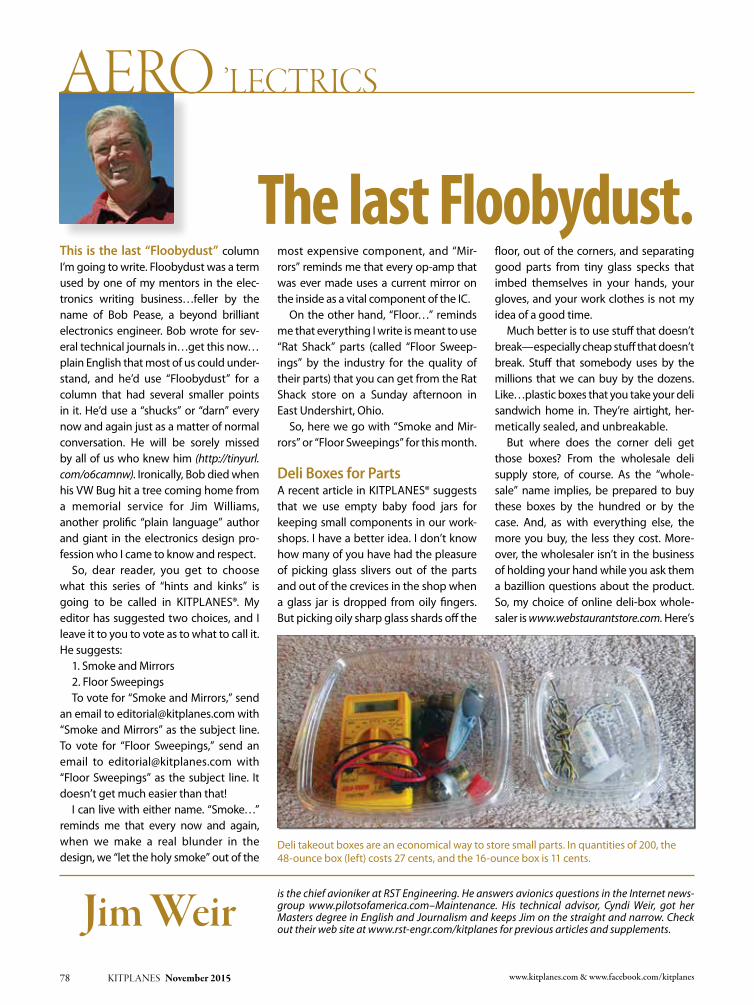
78 KITPLANES November 2015 www.kitplanes.com & www.facebook.com/kitplanes
is the chief avioniker at RST Engineering. He answers avionics questions in the Internet news-group www.pilotsofamerica.com–Maintenance. His technical advisor, Cyndi Weir, got her Masters degree in English and Journalism and keeps Jim on the straight and narrow. Check out their web site at www.rst-engr.com/kitplanes for previous articles and supplements.
Jim Weir
The last Floobydust.This is the last “Floobydust” column I’m going to write. Floobydust was a term used by one of my mentors in the elec-tronics writing business…feller by the name of Bob Pease, a beyond brilliant electronics engineer. Bob wrote for sev-eral technical journals in…get this now…plain English that most of us could under-stand, and he’d use “Floobydust” for a column that had several smaller points in it. He’d use a “shucks” or “darn” every now and again just as a matter of normal conversation. He will be sorely missed by all of us who knew him (http://tinyurl.com/o6camnw). Ironically, Bob died when his VW Bug hit a tree coming home from a memorial service for Jim Williams, another prolific “plain language” author and giant in the electronics design pro-fession who I came to know and respect.
So, dear reader, you get to choose what this series of “hints and kinks” is going to be called in KItPlanES®. My editor has suggested two choices, and I leave it to you to vote as to what to call it. He suggests:
1. Smoke and Mirrors 2. Floor Sweepings to vote for “Smoke and Mirrors,” send
an email to [email protected] with “Smoke and Mirrors” as the subject line. to vote for “Floor Sweepings,” send an email to [email protected] with “Floor Sweepings” as the subject line. It doesn’t get much easier than that!
I can live with either name. “Smoke…” reminds me that every now and again, when we make a real blunder in the design, we “let the holy smoke” out of the
most expensive component, and “Mir-rors” reminds me that every op-amp that was ever made uses a current mirror on the inside as a vital component of the IC.
On the other hand, “Floor…” reminds me that everything I write is meant to use “Rat Shack” parts (called “Floor Sweep-ings” by the industry for the quality of their parts) that you can get from the Rat Shack store on a Sunday afternoon in East Undershirt, Ohio.
So, here we go with “Smoke and Mir-rors” or “Floor Sweepings” for this month.
Deli Boxes for Partsa recent article in KItPlanES® suggests that we use empty baby food jars for keeping small components in our work-shops. I have a better idea. I don’t know how many of you have had the pleasure of picking glass slivers out of the parts and out of the crevices in the shop when a glass jar is dropped from oily fingers. But picking oily sharp glass shards off the
floor, out of the corners, and separating good parts from tiny glass specks that imbed themselves in your hands, your gloves, and your work clothes is not my idea of a good time.
Much better is to use stuff that doesn’t break—especially cheap stuff that doesn’t break. Stuff that somebody uses by the millions that we can buy by the dozens. like…plastic boxes that you take your deli sandwich home in. they’re airtight, her-metically sealed, and unbreakable.
But where does the corner deli get those boxes? From the wholesale deli supply store, of course. as the “whole-sale” name implies, be prepared to buy these boxes by the hundred or by the case. and, as with everything else, the more you buy, the less they cost. More-over, the wholesaler isn’t in the business of holding your hand while you ask them a bazillion questions about the product. So, my choice of online deli-box whole-saler is www.webstaurantstore.com. Here’s
Deli takeout boxes are an economical way to store small parts. In quantities of 200, the 48-ounce box (left) costs 27 cents, and the 16-ounce box is 11 cents.
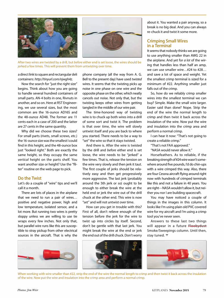
KITPLANES November 2015 79
a direct link to square and rectangular deli containers: http://tinyurl.com/njwgh4z.
now the search for “just the right size” begins. think about how you are going to handle several hundred containers of small parts. an-4 bolts in one, Rivnuts in another, and so on. Here at RSt Engineer-ing, we use several sizes, but the most common are the 16-ounce aD16S and the 48-ounce aD48. the former are 11 cents each in a case of 200 and the latter are 27 cents in the same quantity.
Why did we choose these two sizes? For small parts (rivets, small screws, etc.) the 16-ounce size was the smallest I could find in this height, and the 48-ounce box just “looked right.” Both are exactly the same height, so they occupy the same vertical height on the parts shelf. You want another size or height? Use the “fil-ter” routine on the web page to pick.
Do the Twistlet’s do a couple of “wire” tips and we’ll call it a month.
there are lots of places in the airplane that we need to run a pair of wires…positive and negative power, high and low temperature, isolated sensor, and a lot more. But running two wires is pretty sloppy unless we are willing to use tie wraps every few inches. not only that, but parallel wire runs like this are suscep-tible to stray pickup from other electrical sources in the aircraft. that is why the
phone company (all the way from a. G. Bell to the present day) have used twisted wires. It seems that the twisting picks up noise in one phase on one wire and the opposite phase on the other, which neatly cancels out noise. not only that, but the twisting keeps other wires from getting tangled in the middle of our wire pair.
the time-honored way of twisting wire is to chuck up both wires into a drill of some sort and twist it. the problem is that over time, the wire will slowly untwist itself and you are back to where you started. there needs to be a way to “set” the wire so that it stays twisted.
and there is. after the wire is twisted by the drill and before either end is set loose, the wire needs to be “jerked” a few times. that is, release the tension on the wire very slowly and then jerk it taut. the first couple of jerks should be rela-tively easy and then get progressively more aggressive. the last jerk (probably around the 5th jerk or so) ought to be enough to either break the wire at the held end or jerk the wire out of the drill chuck at the other end. this wire is now “set” and will not untwist over time.
How can you get in trouble with this? First of all, don’t relieve enough of the tension before the jerk for the wire to twist up into circles by itself. Second, don’t be gentle with that last jerk. You might break the wire at the end or jerk the end out of the drill chuck. Don’t worry
about it. You wanted a pair anyway, so a break is no big deal. and you can always re-chuck it and twist it some more.
Crimping Small Wires in a TerminalIt seems that nobody thinks we are going to use anything smaller than aWG 22 in the airplane. and yet for a lot of the wir-ing that handles less than half an amp, we can use smaller wire…#24 to #28…and save a lot of space and weight. Yet the smallest crimp terminal is sized for a minimum of #22. anything smaller just falls out of the crimp.
So, how do we reliably crimp smaller wires into the smallest terminal we can buy? Simple. Make the small wire larger. Easier said than done? nope. Strip the end of the wire the normal length to crimp and then twist it back across the insulation of the wire. now put the wire and insulation into the crimp area and perform a normal crimp.
I can hear it now: “that’s not going to create a reliable crimp.”
“that’s not Faa approved.” “naSa would never allow it.”Horsefeathers. as to reliable, if the
breaking strength of #24 wire wasn’t some-where around five pounds, I’d do chin-ups with a wire crimped this way. also, there are four Cessna aircraft flying around right now with hundreds of crimped terminals like this and not a failure in 40 years. You are right—naSa wouldn’t allow it, but nei-ther you nor I are building spacecraft.
You may have noticed a couple of things in the images in this column. It looks like I’m using plain old PVC covered wire for my aircraft and I’m using a crimp tool you’ve never seen.
answers to these last two things will appear in a future Floobydust Smoke/Sweepings column. Until then, stay tuned. J
Photos: Jim Weir
after two wires are twisted by a drill, but before either end is set loose, the wires should be jerked a few times. this will prevent them from untwisting over time.
When working with wire smaller than #22, strip the end of the wire the normal length to crimp and then twist it back across the insulation of the wire. now put the wire and insulation into the crimp area and perform a normal crimp.
—

www.kitplanes.com & www.facebook.com/kitplanes80 KITPLANES November 2015
By RoBRucha