Kit Part Number: 21-678 - b.cdnbrm.com · 21-678 Instructions 10-6781 4 02.05.09 Rev 4 1. Preparing...
13
AEM Cold Air Intake Systems that are pending an Executive Order number (EO#) relating to exemptions under Section 27156 of the Vehicle Code from the California Air Resource Board (CARB) are for off-road use only in California, which may never be used on public highways. © 2009, Advanced Engine Management, Inc. AEM is a registered trademark of Advanced Engine Management, Inc. All rights reserved. Advanced Engine Management Inc. 2205 126 th Street, Unit A Hawthorne, CA 90250 Phone: 310.484.2322 http://www.aempower.com 2008 Mitsubishi Lancer Evolution X CARB EO #: D-392-31 Equipped with AEM DRYFLOW Filter No Oil Required! Kit Part Number: 21-678
Transcript of Kit Part Number: 21-678 - b.cdnbrm.com · 21-678 Instructions 10-6781 4 02.05.09 Rev 4 1. Preparing...

AEM Cold Air Intake Systems that are pending an Executive Order number (EO#) relating to exemptions under Section 27156 of the VehicleCode from the California Air Resource Board (CARB) are for off-road use only in California, which may never be used on public highways.
© 2009, Advanced Engine Management, Inc. AEM is a registered trademark of Advanced Engine Management, Inc. All rights reserved.
Advanced Engine Management Inc.2205 126th Street, Unit A
Hawthorne, CA 90250Phone: 310.484.2322
http://www.aempower.com
2008 Mitsubishi Lancer Evolution X CARB EO #: D-392-31
Equipped with AEM DRYFLOW FilterNo Oil Required!
Kit Part Number: 21-678

21-678
Instructions 10-6781 02.05.09 Rev 42
516-006 (10”)
94449448
9452

21-678
Instructions 10-6781 02.05.09 Rev 43
Quantity Part Number1 9-67811 2-6781C1 20-67811 5-67811 21-203D2 2-9261 94441 94481 94522 8-148
14 8-1193 516-0063 516-0065 1-1125 1-30014 655324 65532
10 516-0061 1-1242 10-9221 10-67812 1-21052 444.460.042 5599991 1228598
T20 Tamper Resistant TorxAEM Decal
M6 Serrated NutM4X.7 MAF Bolts
#48 Hose Clamp#52 Hose Clamp
Connector, Plastic 5/16" Sponge Rubber Gasket
Hose,5/16IDHose,5/16ID
Button Head M6-1.0 X 10MM
5/8" X 6mm Rubber Mount6mm Washer
Nylon WasherHose,5/32ID
Instructions
Hose,5/32IDHose,5/16ID
Bill of MaterialsPart Description
AirboxAluminum Inlet Pipe
#44 Hose Clamp
Airbox LidRubber Inlet Pipe
3X5" Dryflow FilterConnector, Aluminum 5/16"-5/32"
21-678
Instructions 10-6781 02.05.09 Rev 44
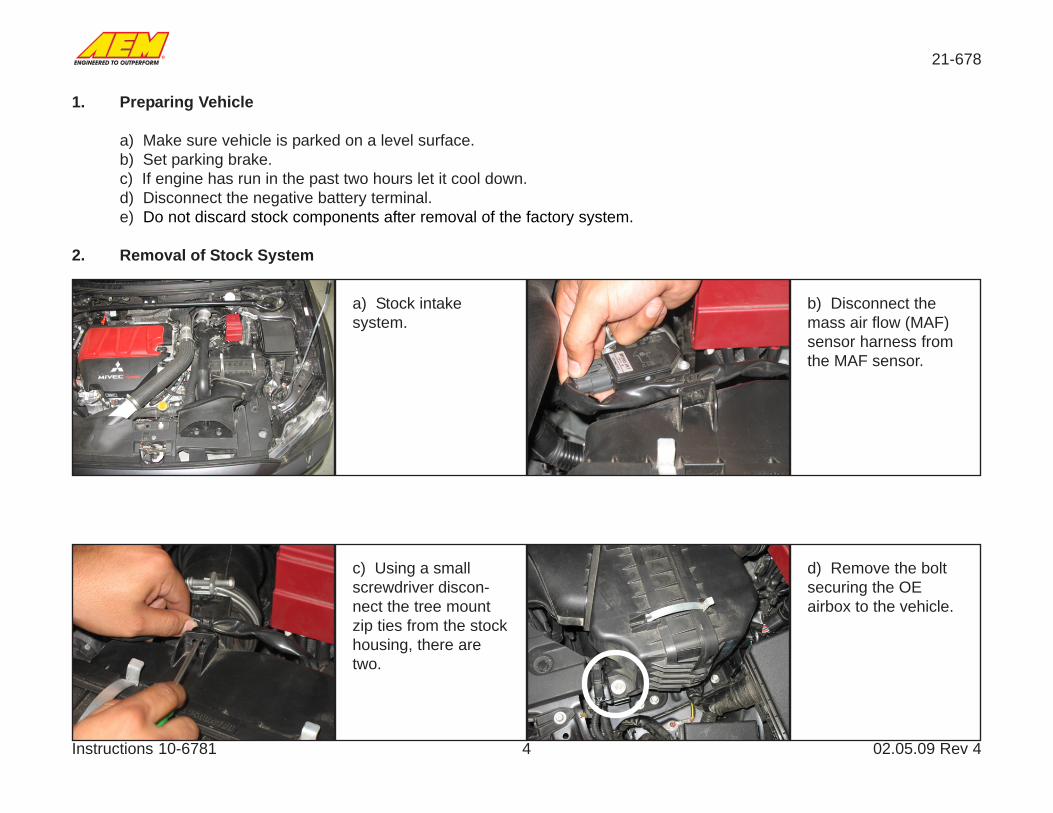
1. Preparing Vehicle
a) Make sure vehicle is parked on a level surface.b) Set parking brake.c) If engine has run in the past two hours let it cool down.d) Disconnect the negative battery terminal.e) Do not discard stock components after removal of the factory system.
2. Removal of Stock System
a) Stock intakesystem.
c) Using a smallscrewdriver discon-nect the tree mountzip ties from the stockhousing, there aretwo.
d) Remove the boltsecuring the OEairbox to the vehicle.
b) Disconnect themass air flow (MAF)sensor harness fromthe MAF sensor.

21-678
Instructions 10-6781 02.05.09 Rev 45
i) Disconnect the airbypass valve hosefrom the airbypassvalve.
j) Use pliers to com-press the hose clampsecuring the vacuumline to the airbypassvalve and move itaway from theairbypass valve.
e) Loosen the hoseclamp securing therubber inlet tube tothe stock airboxassembly.
f) Remove theairbybass valve hosefrom the OE inlet bypulling it toward thepassgenger side ofthe vehicle.
h) Disconnect the OEinlet tube from theairbox and removethe airbox from theengine bay by pullingstraight up.
g) Remove the twoplastic rivets shown inthe pictures.

21-678
Instructions 10-6781 02.05.09 Rev 46
k) Disconnect thevacuum line from theairbypass valve.
l) Disconnect thePCV hose from theOEM inlet tube.
o) Remove thevacuum line from thevehicle that wasconnected to theairbypass valve.
p) Remove theairbypass valve fromthe inlet by looseningthe hose clamp onthe inlet tube.
m) Disconnect thetwo vacuum linesconnected to thewastegate solenoid, itconnects to the inlettube.
n) Loosen the hoseclamp securing theinlet tube to the turboinlet. Remove theinlet tube.

21-678
Instructions 10-6781 02.05.09 Rev 47
q) Remove the hoseclamp from the inlettube.
r) Remove the MAFsensor from theairbox housing usingthe supplied tamperproof torx tool.
s) Unclip the twoclips holding theairbox housing to-gether. And disas-semble the airbox.
t) Remove the inletduct from the airboxby sequeezing the toptwo tabs and pushingout.
u) Remove the twogrommets on thebottom of the airboxhousing to be usedlater.

21-678
Instructions 10-6781 02.05.09 Rev 48
d) Install the two OErubber grommetsremoved in step 2(u)in the two holes onthe bottom of theAEM airbox.
e) Place the AEMairbox in the vehiclealigning the tworubber grommets onthe bottom with thetwo dowels on theairbox mount in thecar.
3. Installation of Cold Air Intake System.
a) When installing the intake system , DO NOT completely tighten the hose clamps or mounting tab hardware until instructed to do so.
b) Install the suppliedrubber mount. Therubber mount shouldbe located on theoutside of the airbox.The washer andsupplied nut shouldsecure it from the
c) The inlet ductshould snap intoplace in the ovalopening, and installthe edge trim aroundthe circular hole onthe back of theairbox.

21-678
Instructions 10-6781 02.05.09 Rev 49
f) Align the tab on theairbox with themounting location ofthe OE airbox anduse the same boltremoved in step 2(d).Do not over torquethe bolts. 15 ft-lbs.
j) Create an assem-bly with the 5/16” IDhose and the twoaluminum transistioncouplers, then con-nect the 5/16” IDhose to the two withconnectors installedin step 3(h).
g) Secure the inletduct using the plasticrivets removed in step2(g).
k) Install the MAFsensor in the alumi-num inlet pipe andsecure with the sup-plied socket bolts.
h) Insert the twowhite connectors intothe rubber inlet hose.(Note: Using glasscleaner to lubricatethe parts will help withinstallation.)
i) Install the air by-pass valve into therubber inlet hose andsecure with the OEhose clamp.
21-678
Instructions 10-6781 02.05.09 Rev 410
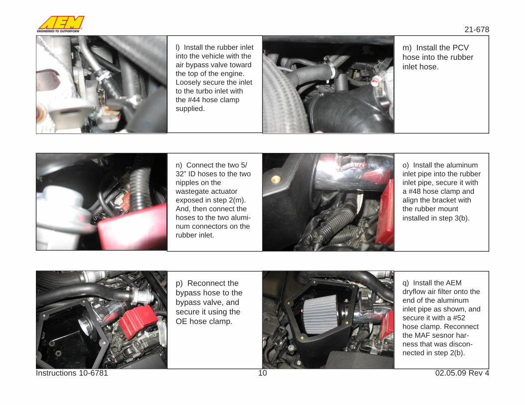
p) Reconnect thebypass hose to thebypass valve, andsecure it using theOE hose clamp.
q) Install the AEMdryflow air filter onto theend of the aluminuminlet pipe as shown, andsecure it with a #52hose clamp. Reconnectthe MAF sesnor har-ness that was discon-nected in step 2(b).
l) Install the rubber inletinto the vehicle with theair bypass valve towardthe top of the engine.Loosely secure the inletto the turbo inlet withthe #44 hose clampsupplied.
m) Install the PCVhose into the rubberinlet hose.
n) Connect the two 5/32” ID hoses to the twonipples on thewastegate actuatorexposed in step 2(m).And, then connect thehoses to the two alumi-num connectors on therubber inlet.
o) Install the aluminuminlet pipe into the rubberinlet pipe, secure it witha #48 hose clamp andalign the bracket withthe rubber mountinstalled in step 3(b).

21-678
Instructions 10-6781 02.05.09 Rev 411
r) Align the holes inthe AEM aluinum lidwith the threadedholes in the airbox.Use the 5 suppliedbutton head screwsand plastic washersto secure the lid to
s) Use the supplied10” of 5/16” ID hoseto connect the bypassvalve and the vacuumtubing exposed instep 2(o).

21-678
Instructions 10-6781 02.05.09 Rev 412
Stock Intake Installed AEM Cold Air Intake System Installed
4. Reassemble Vehicle
a) Position the inlet pipes for best fittment. Be sure that the pipes or any other components do not contact any part ofthe vehicle. Tighten the rubber mount, all bolts and hose clamps.
b) Check for proper hood clearance. Readjust pipes if necessary and re-tighten them.c) Inspect the engine bay for any loose tools and check that all fasteners that were moved or removed are properly
tight.d) Reconnect the negative battery cable to the terminal.e) Start engine. Let car idle for 3 minutes. Perform a final inspection before driving vehicle.

21-678
Instructions 10-6781 02.05.09 Rev 413
AEM Air Intake System Warranty Policy
AEM warrants that its intake systems will last for the life of your vehicle. AEM will not honor this warranty due to mechanical damage (i.e. improper installation or fitment), damage
from misuse, accidents or flying debris. AEM will not warrant its powdercoating if the finish has been cleaned with a hydrocarbon-based solvent. The powdercoating should only be
cleaned with a mild soap and water solution. Proof of purchase of both the vehicle and AEM intake system is required for redemption of a warranty claim.
This warranty is limited to the repair or replacement of the AEM part. In no event shall this warranty exceed the original purchase price of the AEM part nor shall AEM be responsible forspecial, incidental or consequential damages or cost incurred due to the failure of this product. Warranty claims to AEM must be transportation prepaid and accompanied with dated proofof purchase. This warranty applies only to the original purchaser of product and is non-transferable. Improper use or installation, use for racing, accident, abuse, unauthorized repairs oralterations voids this warranty. AEM disclaims any liability for consequential damages due to breach of any written or implied warranty on all products manufactured by AEM. Warrantyreturns will only be accepted by AEM when accompanied by a valid Return Merchandise Authorization (RMA) number. Credit for defective products will be issued pending inspection.Product must be received by AEM within 30 days of the date RMA is issued.
If you have a warranty issue, please call (310) 484-2322, extension 203 and our customer service department will assist you. A proof of purchase is required for all AEM warranty claims.
5. Service and Maintenence
a) It is recommended that you service you AEM dryflow filter every 20,000 miles for optimum performance. UseAEM Dryflow cleaning kit part #21-110.
b) Use aluminum polish to clean your polished AEM Cold Air intake pipe.c) Use window cleaner to clean your powder coated AEM Cold Air intake pipe.
(NOTE: DO NOT USE ALUMINUM POLISH ON A POWDER COATED AEM COLD AIR INTAKE PIPE)
For technical inquiriese-mail us at
call us at310.484.2322 Option # 3