Kit Installation Manual - Bandai Namco Entertainment 3 Kit Installation... · TEKKEN 3 is the...
23
Transcript of Kit Installation Manual - Bandai Namco Entertainment 3 Kit Installation... · TEKKEN 3 is the...
Kit Installation Manual
1.0
2 .0
3 .0
4 .0
5 .0
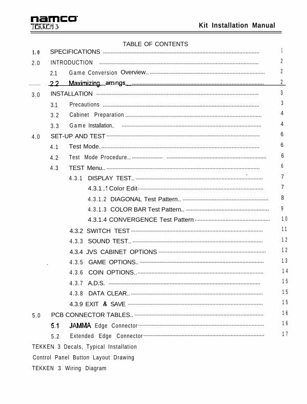
TABLE OF CONTENTSSPECIFICATIONS ...................................................................................................... 1
INTRODUCTION ........................................................................................................ 2
2.1 G a m e Conversion Overview.. ........................................................................... 2
armgs _ ...................................................................................... 2
INSTALLATION .......................................................................................................... 3
3.1 Precautions ...................................................................................................... 3
3 .2 Cabinet Preparation ......................................................................................... 4
3 .3 G a m e Installation.. ........................................................................................... 4
SET-UP AND TEST .................................................................................................... 6
4 .1 Test Mode........................................................................................................ 6
4 .2 Test Mode Procedure.. 6.................... .................................................................
4 .3 TEST Menu.. .................................................................................................... 6.
4 .3 .1 DISPLAY TEST.. ................................................................................... 7
4.3.1 .I Color Edit.................................................................................. 7
4.3 .1 .2 DIAGONAL Test Pattern.. ........................................................ 8
4.3 .1 .3 COLOR BAR Test Pattern.. ...................................................... 9
4.3.1.4 CONVERGENCE Test Pattern ................................................. 1 0
4.3.2 SWITCH TEST ...................................................................................... 1 1
4 .3 .3 SOUND TEST.. ..................................................................................... 1 2
4.3.4 JVS CABINET OPTIONS ...................................................................... 1 2
4 .3 .5 GAME OPTIONS.. ................................................................................. 1 3
4 .3 .6 COIN OPTIONS.................................................................................... 1 4
4 .3 .7 A.D.S. ................................................................................................... 1 5
4 .3 .8 DATA CLEAR.. ...................................................................................... 1 5
4.3.9 EXIT & SAVE ........................................................................................ 1 5
PCB CONNECTOR TABLES.. .................................................................................... 1 6
5.1 JAMMA Edge Connector .................................................................................. 1 6
5 .2 Extended Edge Connector ............................................................................... 1 7
TEKKEN 3 Decals, Typical Instal lat ion
Control Panel Button Layout Drawing
TEKKEN 3 Wiring Diagram

Kit Installation Manual
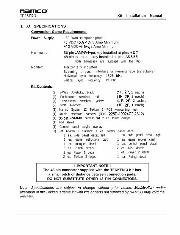
1 .O SPECIFICATIONSConversion Game Reauirements
Power Supply: 150 Watt computer-grade,+5 VDC +5% -I%, 5 Amp Minimum+I 2 VDC +/- 5%, 2 Amp Minimum
Harnesses: 56 pin JAMMA-type, key installed at pins H & 748 pin extension, key installed at pins A5 & I35
(both harnesses are supplied with the Kit)
Monitor:
Kit Contents
Horizontal ly mountedScanning retrace: interlace or non-interlace (selectable)Horizontal sync frequency: 15.75 kHzVertical sync frequency: 60 Hz
(2) 8-Way Joysticks, black: (IP, 2P, 1 each)(4) Push-button switches, red: (IP, 2P, 2 each)(4) Push-button switches, yellow: (1 P, 2P, 2 each).,.(2) Start switches: (IP, 2P, 1 each)(1) Namco System 12 Tekken 3 PCB w/mounting feet(1) 48-pin extension harness (DDK 225D-10024C2-2312)(1) 56-pin JAMMA harness w/ 2 ea. ferrite clamps(1) Foil shield(1) Control panel acrylic overlay(1) Set Tekken 3 graphics: 1 ea. control panel decal
1 ea. side panel decal, left 1 ea. side panel decal, right1 ea. game instructions card 1 ea. game moves card1 ea. marquee decal 1 ea. control panel decal2 ea. Punch decals 2 ea. Kick decals1 ea. Player 1 decal 1 ea. Player 2 decal2 ea. Tekken 3 logos 1 ea. Rating decal
! IMPORTANT NOTE !The 48-pin connector supplied with the TEKKEN 3 Kit has
a small pitch or distance between connection pads.DO NOT SUBSTITUTE OTHER 48 PIN CONNECTORS.
Note: Specifications are subject to change without prior notice. Modificafion and/oralteration of the Tekken 3 game kit with kits or parts not supplied by NAMCO may void thewarranty.
Kit Installation Manual
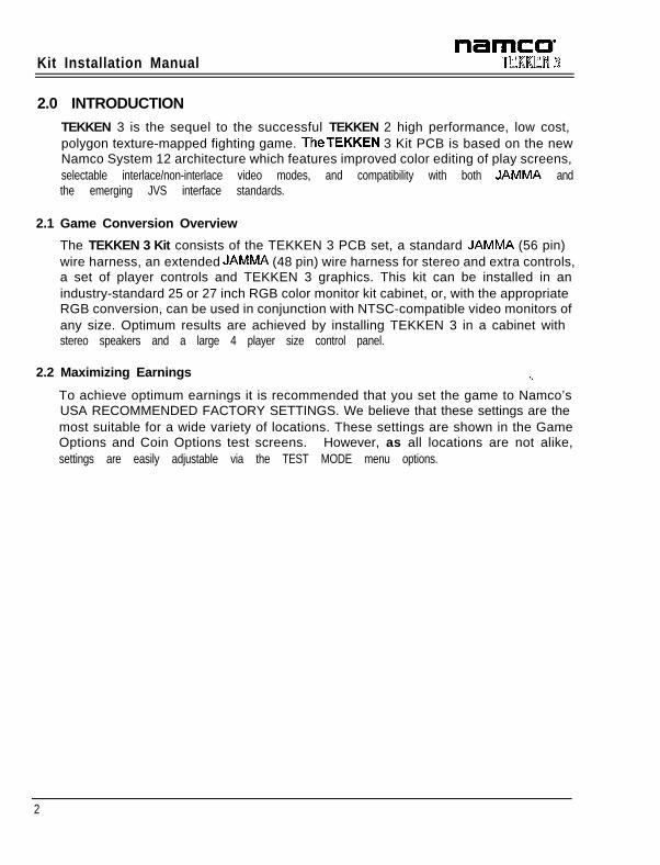
2.0 INTRODUCTION
TEKKEN 3 is the sequel to the successful TEKKEN 2 high performance, low cost,polygon texture-mapped fighting game. TheTEKKEN 3 Kit PCB is based on the newNamco System 12 architecture which features improved color editing of play screens,selectable interlace/non-interlace video modes, and compatibility with both JAMMA andthe emerging JVS interface standards.
2.1 Game Conversion Overview
The TEKKEN 3 Kit consists of the TEKKEN 3 PCB set, a standard JAMMA (56 pin)wire harness, an extended JAMMA (48 pin) wire harness for stereo and extra controls,a set of player controls and TEKKEN 3 graphics. This kit can be installed in anindustry-standard 25 or 27 inch RGB color monitor kit cabinet, or, with the appropriateRGB conversion, can be used in conjunction with NTSC-compatible video monitors ofany size. Optimum results are achieved by installing TEKKEN 3 in a cabinet withstereo speakers and a large 4 player size control panel.
2.2 Maximizing Earnings -.
To achieve optimum earnings it is recommended that you set the game to Namco’sUSA RECOMMENDED FACTORY SETTINGS. We believe that these settings are themost suitable for a wide variety of locations. These settings are shown in the GameOptions and Coin Options test screens. However, as all locations are not alike,settings are easily adjustable via the TEST MODE menu options.
2

Kit Installation Manual
3.0 INSTALLATION
Note: Shipping damage may void the warranty. In case of shipping damage, contact yourdistributor and the transportation carrier immediately.
CAUTIONThe electronic installation should be performed by experienced Game technicians only.Existing game wiring must be made compatible with the enclosed JAMMA wire list. Wiringshould be completely checked and double-checked for continuity and shorts prior toapplication of power to the game PCB. Damage caused by faulty wiring will void thewarranty.
Before beginning the installation, verify that the kit contents match the enclosed kitparts list.
3.1 Precautions
1. Turn power to the cabinet off before installing or removing any electroniccomponents.
2. The TEKKEN 3 PCB is a state of the art custom polygon graphics system that isvery sensitive to electro-static discharge (ESD). Be sure to use appropriate ESDreduction procedures such as use of ground straps and handling the PCB using theanti-static material provided.
3. Dust or foreign matter may cause PCB failure. Dust can be removed using cannedcompressed air available at electronics supply stores. Turn the power off beforecleaning the PCB.
4. The TEKKEN 3 PCB can be damaged by even the small internal voltage of amultimeter. Never attempt to troubleshoot the PCB with such instruments. In the
event of a PCB failure please contact your distributor for factory repairs.
5. If the game PCB must be returned for repairs, wrap it in a suitable anti-static foamor bubble wrap, include a note indicating the nature of the trouble(s), and label thereturn carton with the RMA number obtained through your distributor.
6. If measurements must be taken while the system is operational, use extreme careto prevent contact with exposed AC or high-voltage monitor components.
3
Kit installation Manual
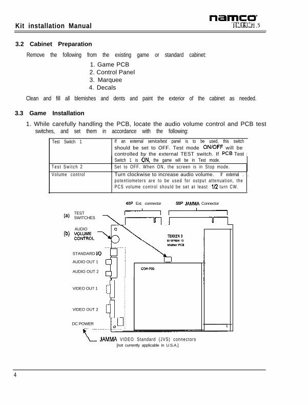
3.2 Cabinet Preparation
Remove the following from the existing game or standard cabinet:
1. Game PCB2. Control Panel3. Marquee4. Decals
Clean and fill all blemishes and dents and paint the exterior of the cabinet as needed.
3.3 Game Installation
1. While carefully handling the PCB, locate the audio volume control and PCB testswitches, and set them in accordance with the following:
Test Switch 1
T e s t S w i t c h 2
Volume cont ro l
If an external service/test panel is to be used, this switchshould be set to OFF. Test mode ON/OFF will becontrolled by the external TEST switch. If PCS TestSwitch 1 is dN, the game will be in Test mode.
I
1 Set to OFF. When ON, the screen is in Stop mode.
Turn clockwise to increase audio volume. If external . .po tent iometers are to be used for output a t tenuat ion, thePCS vo lume con t ro l shou ld be se t a t leas t l/2 turn CW.
48P Ext. connector 56P JAMMA Connector
(a)TEST -rSWITCHES\Iul
TEKKEN 3
AUDIOlb) KUJ;~ \
STANDARD I/O
AUDIO OUT 1
AUDIO OUT 2
VIDEO OUT 1
VIDEO OUT 2
DC POWER
2 “”L JAMMA VIDEO Standard (JVS) connectors
[not currently applicable in U.S.A.]
4

name0TfRREM 3 Kit Installation Manual
2.
3.
4.
5.
6.
7.
8.
9.
I O
Mount the game PCB to the inside of the game cabinet, such that there isadequate ventilation provided for the PCB heat sink and that clearance is providedfor the EMI Shield Box. Verify that the 56-pin JAMMA harness is equipped with the2 ferrite-core elements (provided with the kit harness). When the installation iscompleted, these ferrite elements should be located within a few inches of the EMIShield Box.
Place the 56-pin and 48-pin wire harnesses in the cabinet, making sure there isadequate length for service loops.
Make the appropriate connections to the power supply. Do not turn on power yet.
Connect the monitor.
Connect the coin door and the coin meter.
Connect the test/service panel.
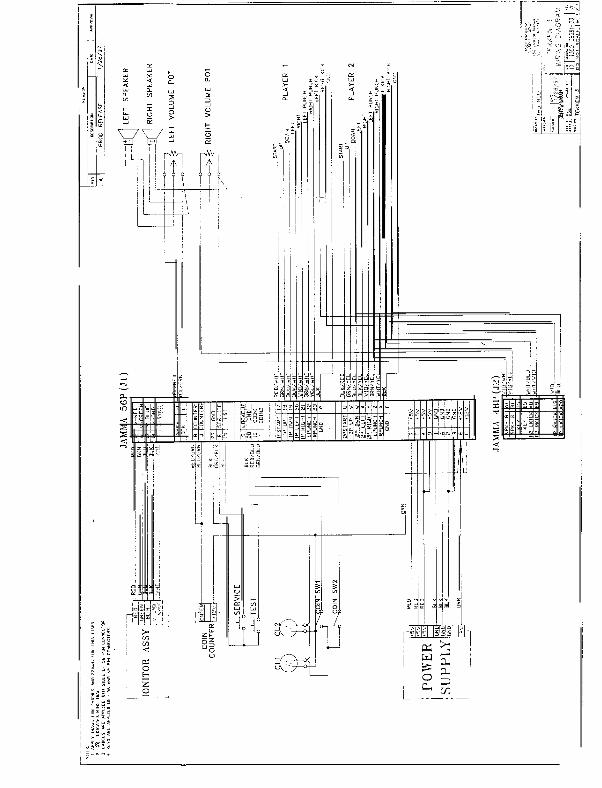
Connect the speakers to the wire harness. If optional volume potentiometers areto be used, wire in accordance with the enclosed TEKKEN 3 Wring Diagram[T350-06581-001.
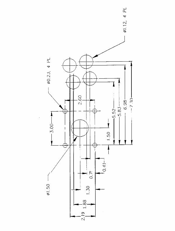
On the control panel, locate the joystick and push-button holes as shown in theenclosed layout drawing. Be sure to check the clearance for the push buttons andjoysticks under the control pane/ before punching fhe holes.
Install the TEKKEN 3 control panel decal and overlay provided in the kit. Using thecontrol panel cutouts as a guide, trim the overlay to fit. Apply the Kick, Punch andPlayer 1 & 2 labels provided with the kit.
11. Install and connect the push button switches.
12. Install and connect the joysticks.
13. Install the control panel on the cabinet and connect the control panel wire harnessto the game wire harness.
14. Use the TEKKEN 3 Wiring Diagram as a guide to verify system connections priorto turning on the power. Tie off any unused wires.
15. Install the cabinet side graphics provided. Float the graphics on by applying aspray of general purpose cleaner to the side wall. Smooth out the bubbles andliquid with a paint squeegee. Wipe the side decal dry with a soft cloth. Repeat forthe opposite side.
16. Install the marquee overlay provided in the kit in place of the existing marquee.
17. Install the game play and game moves instruction cards provided with the kit.
18. If needed, trim the graphics to fit the particular cabinet.
19. Turn on the system power. Adjust system settings in TEST mode.
5
Kit Installation Manual
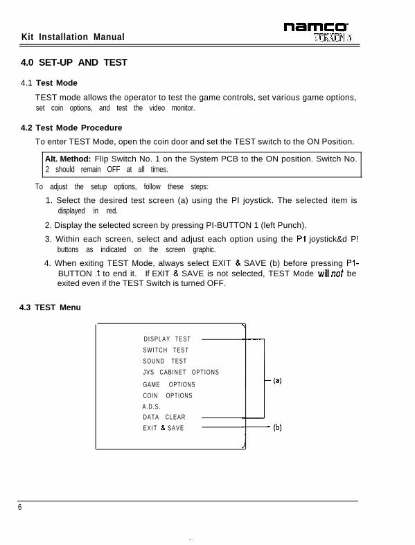
4.0 SET-UP AND TEST
4.1 Test Mode
TEST mode allows the operator to test the game controls, set various game options,set coin options, and test the video monitor.
4.2 Test Mode Procedure
To enter TEST Mode, open the coin door and set the TEST switch to the ON Position.
Alt. Method: Flip Switch No. 1 on the System PCB to the ON position. Switch No.2 should remain OFF at all times.
To adjust the setup options, follow these steps:
1. Select the desired test screen (a) using the PI joystick. The selected item isdisplayed in red.
2. Display the selected screen by pressing PI-BUTTON 1 (left Punch).
3. Within each screen, select and adjust each option using the Pl joystick&d P!buttons as indicated on the screen graphic.
4. When exiting TEST Mode, always select EXIT & SAVE (b) before pressing Pl-BUTTON .I to end it. If EXIT & SAVE is not selected, TEST Mode willnot beexited even if the TEST Switch is turned OFF.
4.3 TEST Menu
DISPLAY TEST
SWITCH TEST
SOUND TEST
JVS CABINET OPTIONS
GAME OPTIONS
COIN OPTIONS
A.D.S.
DATA CLEAR
E X I T 8. SAVE
(4- (b)
6
Kit Installation Manual
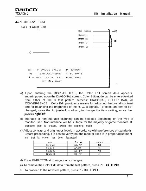
4.3.1 DISPLAY TEST
4.3.1 .I Color Edit/ Non Interlace
Contrast :
Brighi R :
Bright G:
Bright B:
(4
(d) - - PREVIOUS VALUE: PI - BUTTON 4
(e) - - EXITCOLOREDIT: Pl -BUTTON 3
(f) - - NEXT COLOR TEST: PI - BUTTON 1
EXIT: Pi - START
- (b)
1w
..,
a) Upon entering the DISPLAY TEST, the Color Edit screen data appearssuperimposed upon the DIAGONAL screen. Color Edit mode can be entered/exitedfrom either of the 3 test pattern screens: DIAGONAL, COLOR BAR, orCONVERGENCE. Color Edit provides a means for adjusting the overall contrastand for balancing the brightness of the R, G, B signals. To select an item to bechanged, move the PI joystock up/down; to change the item setting, move thejoystick right/left.
b) Interlace or non-interlace scanning can be selected depending on the type ofmonitor used. Non-interlace will be suitable for the majority of game monitors. If
’ excessive jitter is present, switch the scanning mode.
c) Adjust contrast and brightness levels in accordance with preferences or standards.Before proceeding, it is best to verify that the monitor itself is in proper adjustmentand that its screen has been degaussed.
I temContrastBright RBright GBright B
Ranqe00 - FF00 -FF00 - FF00 - FF
DefaultA0181818
d) Press PI-BUTTON 4 to negate any changes.
e) To remove the Color Edit data from the test pattern, press PI - BUlTON 3.
f ) To proceed to the next test pattern, press PI - BUTTON 1.
7
Kit Installation Manual
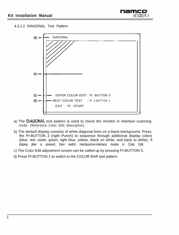
4.3.1.2 DIAGONAL Test Pattern
(4 -
(b) -
w -(4 -
- DIAGONAL
- ENTER COLOR EDIT : PI -BUTTON 3
- NEXT COLOR TEST : P I - B U T T O N 1
EXIT : PI -START
-J
a) The DIAGOtiAL test pattern is used to check the monitor in interlace scanningmode. (Reference Color Edit descript ion).
b) The default display consists of white diagonal lines on a black background. Pressthe PI-BUTTON 2 (right Punch) to sequence through additional display colors(blue, red, violet, green, light blue, yellow, black on white, and back to white). Ifdisplay jitter is present, then switch interlace/non-interlace modes in Color Edit.
c) The Color Edit adjustment screen can be called up by pressing PI-BUTTON 3.
d) Press PI-BUTTON 1 to switch to the COLOR BAR test pattern.
8
nameo-UCRRCN 3 Kit Installation Manual
4.3.1.3 COLOR BAR Test Pattern
(b)
(4 - - COLOR BAR
I-i---------1-E-/-
(cl tENTER COLOR EDIT : Pl - BUTTON 3
(4-I-
NEXT COLOR TEST : Pl - BUnON 1
EXIT : Pl -START
- WHITE
- RED
- GREEN
- BLUE
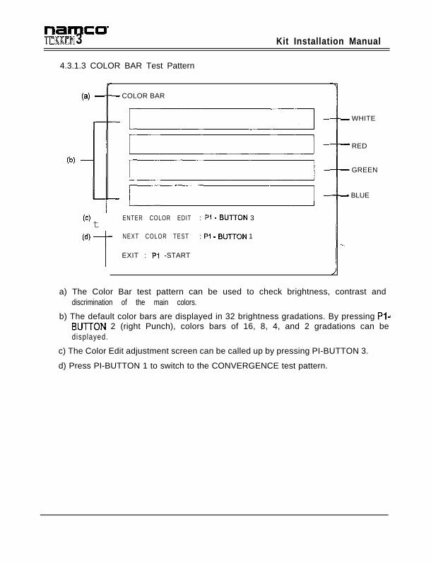
a) The Color Bar test pattern can be used to check brightness, contrast anddiscrimination of the main colors.
b) The default color bars are displayed in 32 brightness gradations. By pressing Pl-BUTTON 2 (right Punch), colors bars of 16, 8, 4, and 2 gradations can bedisplayed.
c) The Color Edit adjustment screen can be called up by pressing PI-BUTTON 3.
d) Press PI-BUTTON 1 to switch to the CONVERGENCE test pattern.
Kit Installation Manual
4.3.1.4 CONVERGENCE Test Pattern
(4(4 C O N V E R G E N C E
/I(cl EfrTER C O L O R E D I T : Pl - Bull-ON 3
(d) NEXT COLOR TEST : Pl - B U T T O N 1
: Pl -START
(b)
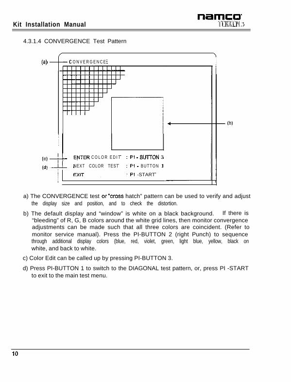
a) The CONVERGENCE test orycross hatch” pattern can be used to verify and adjustthe display size and position, and to check the distortion.
b) The default display and “window” is white on a black background. If there is“bleeding” of R, G, B colors around the white grid lines, then monitor convergenceadjustments can be made such that all three colors are coincident. (Refer tomonitor service manual). Press the PI-BUTTON 2 (right Punch) to sequencethrough additional display colors (blue, red, violet, green, light blue, yellow, black onwhite, and back to white.
c) Color Edit can be called up by pressing PI-BUTTON 3.
d) Press PI-BUTTON 1 to switch to the DIAGONAL test pattern, or, press PI -STARTto exit to the main test menu.
IO
Kit Installation Manual
4.3.2 SWITCH TEST
0) -(d) SWITCH TEST
- IP: oo60m~m~
SERVICE : OFF/ON
TEST SW : ON
DIP SW 1 : OFFDIP SW 2 : OFF
- EXIT: PI-BUTTON 3 & 4
Notes:
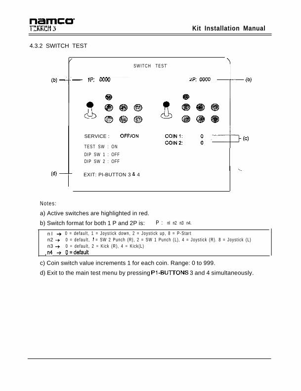
a) Active switches are highlighted in red.
b) Switch format for both 1 P and 2P is: P : nl n2 n3 n4.
n l -+ 0 = defau l t , 1 = Joyst ick down, 2 = Joyst ick up, 8 = P-Star tn2 -+ 0 = defau l t , 1 = SW 2 Punch (R) , 2 = SW 1 Punch (L) , 4 = Joyst ick (R) . 8 = Joyst ick (L)n3 -+ 0 = defaul t , 2 = Kick (R) , 4 = Kick(L)
,n4 + O=default
c) Coin switch value increments 1 for each coin. Range: 0 to 999.
d) Exit to the main test menu by pressing PI-BUlTONS 3 and 4 simultaneously.
Kit Installation Manual
4.3.3 SOUND TEST
SOUND TEST
(b) c :tTti :
[ 000 I
0000
Notes:
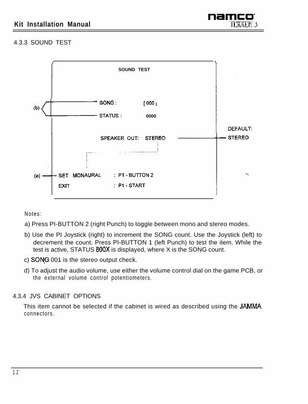
a) Press PI-BUTTON 2 (right Punch) to toggle between mono and stereo modes.
b) Use the PI Joystick (right) to increment the SONG count. Use the Joystick (left) todecrement the count. Press PI-BUTTON 1 (left Punch) to test the item. While thetest is active, STATUS 800X is displayed, where X is the SONG count.
c) SON,G 001 is the stereo output check.
d) To adjust the audio volume, use either the volume control dial on the game PCB, orthe external volume control potent iometers.
4.3.4 JVS CABINET OPTIONS
This item cannot be selected if the cabinet is wired as described using the JAMMAconnectors.
1 2
Kit Installation Manual
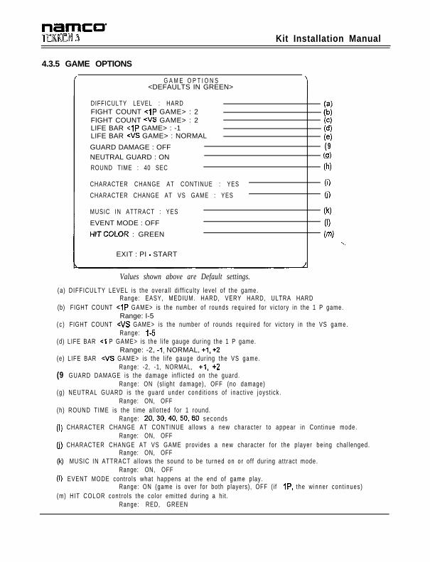
4.3.5 GAME OPTIONS
G A M E O P T I O N S<DEFAULTS IN GREEN>
DIFFICULTY LEVEL : HARDFIGHT COUNT <iP GAME> : 2FIGHT COUNT <VS GAME> : 2LIFE BAR <lP GAME> : -1LIFE BAR +WS GAME> : NORMAL
GUARD DAMAGE : OFFNEUTRAL GUARD : ON
ROUND TIME : 40 SEC
;dc;(e)( 9(9)
(h)
CHARACTER CHANGE AT CONTINUE : YES
CHARACTER CHANGE AT VS GAME : YES
MUSIC IN ATTRACT : YES
EVENT MODE : OFF
HITCOLOR : GREEN
EXIT : PI - START
(0
0)
04
(1)
(m)-..
,
Values shown above are Default settings.
(a ) DIFFICULTY LEVEL is the overa l l d i f f i cu l ty leve l o f the game.Range: EASY, MEDIUM. HARD, VERY HARD, ULTRA HARD
(b) FIGHT COUNT <lP GAME> is the number of rounds requi red for v ic tory in the 1 P game.Range: I-5
( c ) FIGHT COUNT WS GAME> is the number of rounds requi red for v ic tory in the VS game.Range: I-5
(d) LIFE BAR ~1 P GAME> is the l i fe gauge dur ing the 1 P game.Range: -2, -1, NORMAL, +l, +2
(e) LIFE BAR <VS GAME> is the l i fe gauge dur ing the VS game.Range: -2, -1, NORMAL, +l, +2
(9 GUARD DAMAGE is the damage in f l ic ted on the guard.Range: ON (s l ight damage), OFF (no damage)
(g) NEUTRAL GUARD is the guard under condi t ions o f inact ive joyst ick .Range: ON, OFF
(h) ROUND TIME is the t ime a l lo t ted for 1 round.Range: 20,30,40,50,60 seconds
(I) CHARACTER CHANGE AT CONTINUE a l lows a new character to appear in Cont inue mode.Range: ON, OFF
(j) CHARACTER CHANGE AT VS GAME prov ides a new character for the p layer be ing chal lenged.Range: ON, OFF
(k) MUSIC IN ATTRACT a l lows the sound to be turned on or o f f dur ing a t t rac t mode.Range: ON, OFF
(I) EVENT MODE contro ls what happens at the end of game p lay.Range: ON (game is over for both players), OFF ( i f IP, the w inner con t inues)
(m) HIT COLOR cont ro ls the co lor emi t ted dur ing a h i t .Range: RED, GREEN
Kit Installation Manual
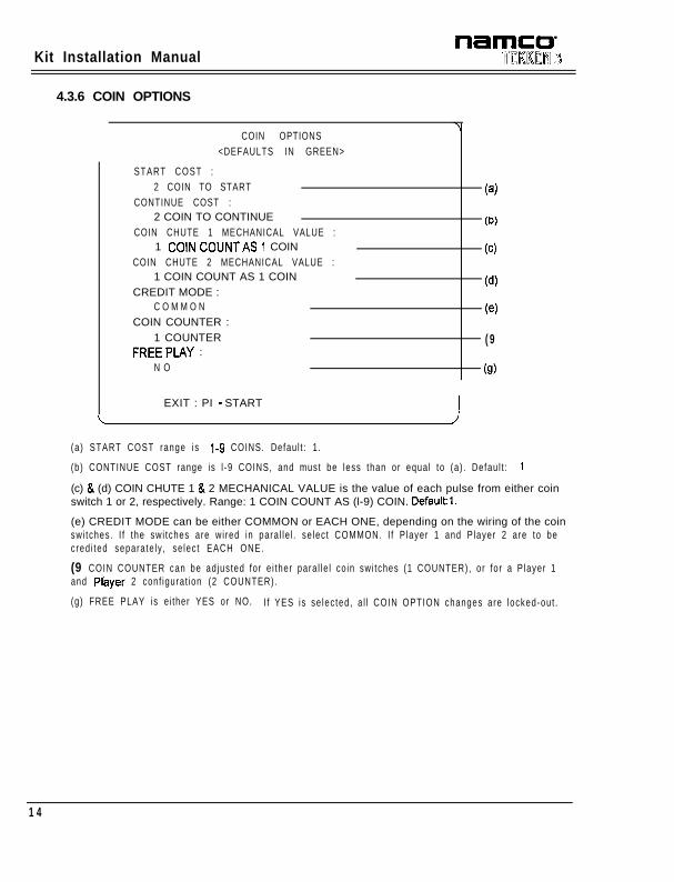
4.3.6 COIN OPTIONS
COIN OPTIONS<DEFAULTS IN GREEN>
START COST :2 COIN TO START
CONTINUE COST :2 COIN TO CONTINUE
COIN CHUTE 1 MECHANICAL VALUE :1 COINCOUNTAS I COIN
COIN CHUTE 2 MECHANICAL VALUE :1 COIN COUNT AS 1 COIN
CREDIT MODE :C O M M O N
COIN COUNTER :1 COUNTER
FREEPLAY :N O
(4
UN
(4
(4
W
( 9
(9)
EXIT : PI - START
L J
(a) START COST range is I-9 COINS. Defaul t : 1 .
(b) CONTINUE COST range is l -9 COINS, and must be less than or equal to (a) . Defau l t : I
(c) & (d) COIN CHUTE 1 & 2 MECHANICAL VALUE is the value of each pulse from either coinswitch 1 or 2, respectively. Range: 1 COIN COUNT AS (l-9) COIN. Defaultl.
(e) CREDIT MODE can be either COMMON or EACH ONE, depending on the wiring of the coinswi tches. I f the swi tches are wi red in para l le l . se lec t COMMON. I f P layer 1 and P layer 2 are to becred i ted separa te ly , se lec t EACH ONE.
(9 COIN COUNTER can be ad jus ted for e i ther para l le l co in swi tches (1 COUNTER), or for a P layer 1and Player 2 conf igurat ion (2 COUNTER).
(g) FREE PLAY is e i ther YES or NO. I f YES is se lec ted , a l l COIN OPTION changes are locked-out .
1 4
Kit Installation Manual
4.3.7 A.D.S.
This mode provides data on play time in each mode, coin totals, character selectionpercentages, and VS game win/loss.
To select the display screen, press PI - BUTTON 1.
To return to the main test menu, press the PI - START switch.
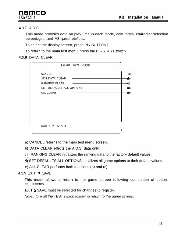
43.8 DATA CLEAR/
BACKUP DATA CLEAR
C A N C E L
ADS DATA CLEAR
RANKING CLEAR
SET DEFAULTS ALL OPTIONS
ALL CLEAR
(a)
(b)
6)
W
63
I EXIT : PI -STARTI
a) CANCEL returns to the main test menu screen.
b) DATA CLEAR effects the A.D.S. data only.
c) RANKING CLEAR initializes the ranking data to the factory default values.
dj SET DEFAULTS ALL OPTIONS initializes all game options to their default values.
e) ALL CLEAR performs both functions (b) and (c).
4.3.9 EXIT & SAVE
This mode allows a return to the game screen following completion of optionadjustments.
EXIT 8 SAVE must be selected for changes to register.
Note:. turn off the TEST switch following return to the game screen.
1 5
Kit Installation Manual
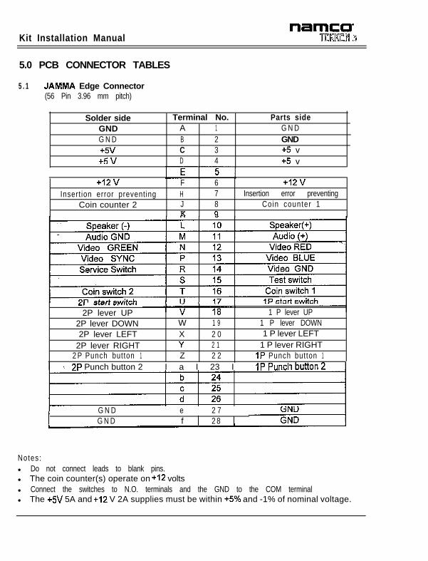
5.0 PCB CONNECTOR TABLES
5 . 1 JAMMA Edge Connector(56 Pin 3.96 mm pitch)
Solder side Terminal No.GND A 1G N D B 2+5v C 3+5v D 4
Parts sideG N DGND+5 v+5 v
+12v F 6 +12vInsert ion error preventing H 7 Insertion error preventing
Coin counter 2 J 8 Coin counter 1K cl
Lr -_-.- -_ -._-..
2P lever UP2P lever DOWN2P lever LEFT
2P lever RIGHT2 P Punch button 1
1 P lever UPW 1 9 1 P lever DOWNX 2 0 1 P lever LEFTY 2 1 1 P lever RIGHTZ 2 2 IP Punch button 1
r->P Punch button 2 I a I 23 I IP Puncl
G N D1 1
e1 1
2 7t G N D f 2 8 1 1
Notes:l Do not connect leads to blank pins.l The coin counter(s) operate on +I2 voltsl Connect the switches to N.O. terminals and the GND to the COM terminall The +5V 5A and +I2 V 2A supplies must be within +5% and -1% of nominal voltage.
name=.TCRREM 3 Kit Installation Manual
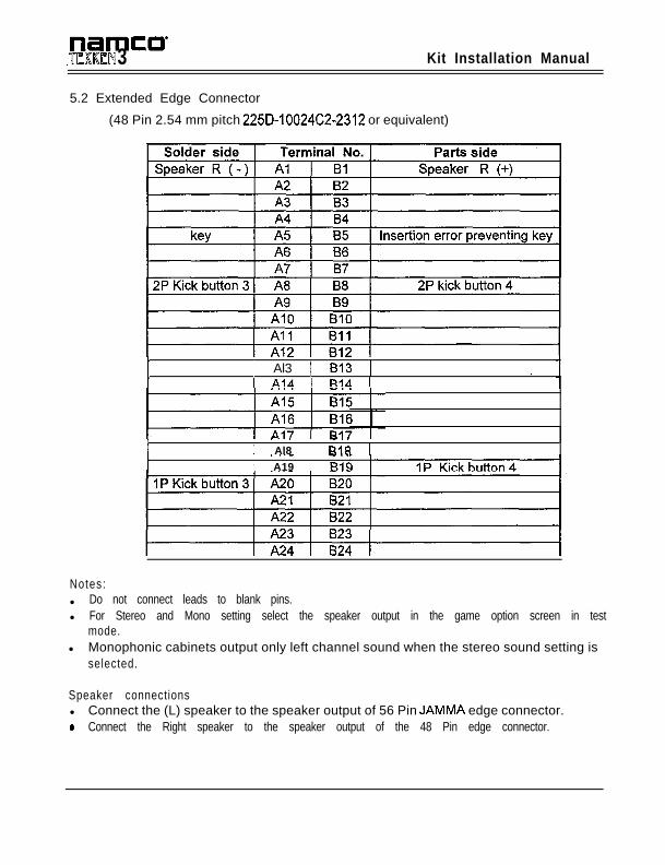
5.2 Extended Edge Connector
(48 Pin 2.54 mm pitch 225D-10024C2-2312 or equivalent)
I 1 Al3 1 813 1 .i AIA 1 R-IA i
I~ . . . - . .
1 Al8 1 RI8 i
I. ..- - ._
1 A19 1 BIE
Notes:l Do not connect leads to blank pins.l For Stereo and Mono setting select the speaker output in the game option screen in test
mode.l Monophonic cabinets output only left channel sound when the stereo sound setting is
selected.
Speaker connectionsl Connect the (L) speaker to the speaker output of 56 Pin JAMMA edge connector.9 Connect the Right speaker to the speaker output of the 48 Pin edge connector.
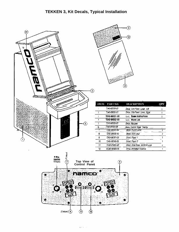
TEKKEN 3, Kit Decals, Typical Installation
1 T340-C6550.W Decal StiePanel. LOwe< Len 12 T340-h%SO-01 Dmi S,dePanel Lower. RIghI 1
3 T640-66551-00 Card, Gamelnstruelionr 14 1340.06552-00 Card. Mov6Lisl t5 r348-116553-w Deal, Marquee6 T341FG5554hl Del-d/, conm Panel overlay i
PYI-Way
Joysllck $
aPhes~ 7I Q
Top View ofControl Panel
T
-