
Kinematics, Dynamics, And Design of Machinery, K. J. Waldron and G. L. Kinzel SOLUTIONS
60
SUPPLEMENTAL EXERCISE PROBLEMS for Textbook Kinematics, Dynamics, and Design of Machinery by K. J. Waldron and G. L. Kinzel ©1996-97 by K. Waldron and G. Kinzel Department of Mechanical Engineering
-
Upload
sixto-gerardo-ona-anaguano -
Category
Documents
-
view
4.400 -
download
19
Transcript of Kinematics, Dynamics, And Design of Machinery, K. J. Waldron and G. L. Kinzel SOLUTIONS

SUPPLEMENTAL EXERCISE PROBLEMS
for Textbook
Kinematics, Dynamics, and Design ofMachinery
byK. J. Waldron and G. L. Kinzel
©1996-97 by K. Waldron and G. Kinzel
Department of Mechanical Engineering
Familia
Text box
http://www.iust.ac.ir/files/mech/madoliat_bcc09/pdf/SUPPLEMENTAL%20EXERCISE%20PROBLEMS.pdf

- ii -

- 1 -
Supplemental Exercise Problems
for
Kinematics, Dynamics, and Design of Machinery
by
K. J. Waldron and G. L. Kinzel
Supplemental Exercise Problems for Chapter 1
Problem S1.1
What are the number of members, number of joints, and mobility of each of the planar linkagesshown below?
(a) (b) (c)
AAAAAAAA
AAAAAAAAAA AA
AAAA
AAAAAAAA
AAAA
AAAAAA
Problem S1.2
Determine the mobility and the number of idle degrees of freedom of each of the planar linkagesshown below. Show the equations used to determine your answers.
(a) (b) (c)
- 2 -
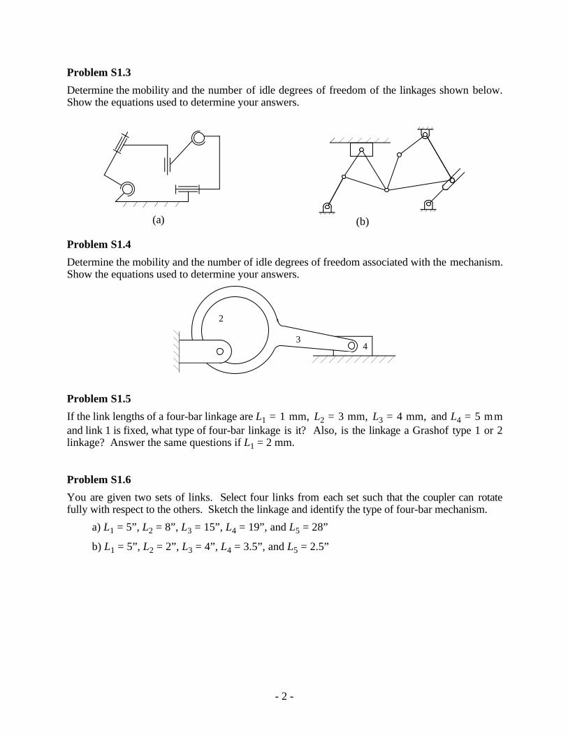
Problem S1.3
Determine the mobility and the number of idle degrees of freedom of the linkages shown below.Show the equations used to determine your answers.
(a) (b)
Problem S1.4
Determine the mobility and the number of idle degrees of freedom associated with the mechanism.Show the equations used to determine your answers.
2
34
Problem S1.5
If the link lengths of a four-bar linkage are L1 = 1 mm, L2 = 3 mm, L3 = 4 mm, and L4 = 5 mmand link 1 is fixed, what type of four-bar linkage is it? Also, is the linkage a Grashof type 1 or 2linkage? Answer the same questions if L1 = 2 mm.
Problem S1.6
You are given two sets of links. Select four links from each set such that the coupler can rotatefully with respect to the others. Sketch the linkage and identify the type of four-bar mechanism.
a) L1 = 5”, L2 = 8”, L3 = 15”, L4 = 19”, and L5 = 28”
b) L1 = 5”, L2 = 2”, L3 = 4”, L4 = 3.5”, and L5 = 2.5”

- 3 -
Supplemental Exercise Problems for Chapter 2
Problem S2.1
Draw the velocity polygon to determine the following:
a) Sliding velocity of link 6
b) Angular velocities of links 3 and 5
2
4
56
B
C
D
E
F
= 3ω2rads
50˚
10.4"
2.0"
29.5"
A
AB = 12.5"BC = 22.4"DC = 27.9"CE = 28.0"DF = 21.5"
3
34˚

- 4 -
Problem S2.2
In the mechanism shown, 1vA2 = 15 m/s. Draw the velocity polygon, and determine the velocityof point D on link 6 and the angular velocity of link 5 (show all calculations).
1vA2= 15 m/s
2
3
4
5
A
C
B
D
45˚
2.05"
AC = 2.4"BD = 3.7"BC = 1.2"
X
Y
2.4"
6
- 5 -
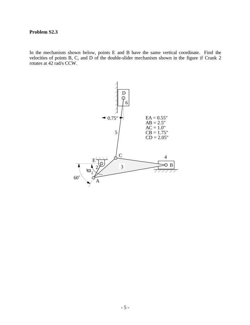
Problem S2.3
In the mechanism shown below, points E and B have the same vertical coordinate. Find thevelocities of points B, C, and D of the double-slider mechanism shown in the figure if Crank 2rotates at 42 rad/s CCW.
A
D
C
2
6
5
B
4
33E
ω 21
0.75"
60˚
EA = 0.55"AB = 2.5"AC = 1.0"CB = 1.75"CD = 2.05"

- 6 -
Problem S2.4
In the figure below, points A and C have the same horizontal coordinate, and 1ω3 = 30 rad/s.Draw and dimension the velocity polygon. Identify the sliding velocity between the block and theslide, and find the angular velocity of link 2.
4
2
B3 , B4
A
ω 31
3
AC = 1 inBC = 3 inr = 2.8 in
C
45˚

- 7 -
Problem S2.5
The following are given for the mechanism shown in the figure:
1 2 1 26 5 40ω α= =. rad/ s (CCW); rad/ s (CCW)2
Draw the velocity polygon, and locate the velocity of Point E using the image technique.
A
C
B
D (2.2", 1.1")
23
4
E
55˚X
Y
AB = DE = 1.0 inBC = 2.0 inCD = 1.5 in
- 8 -
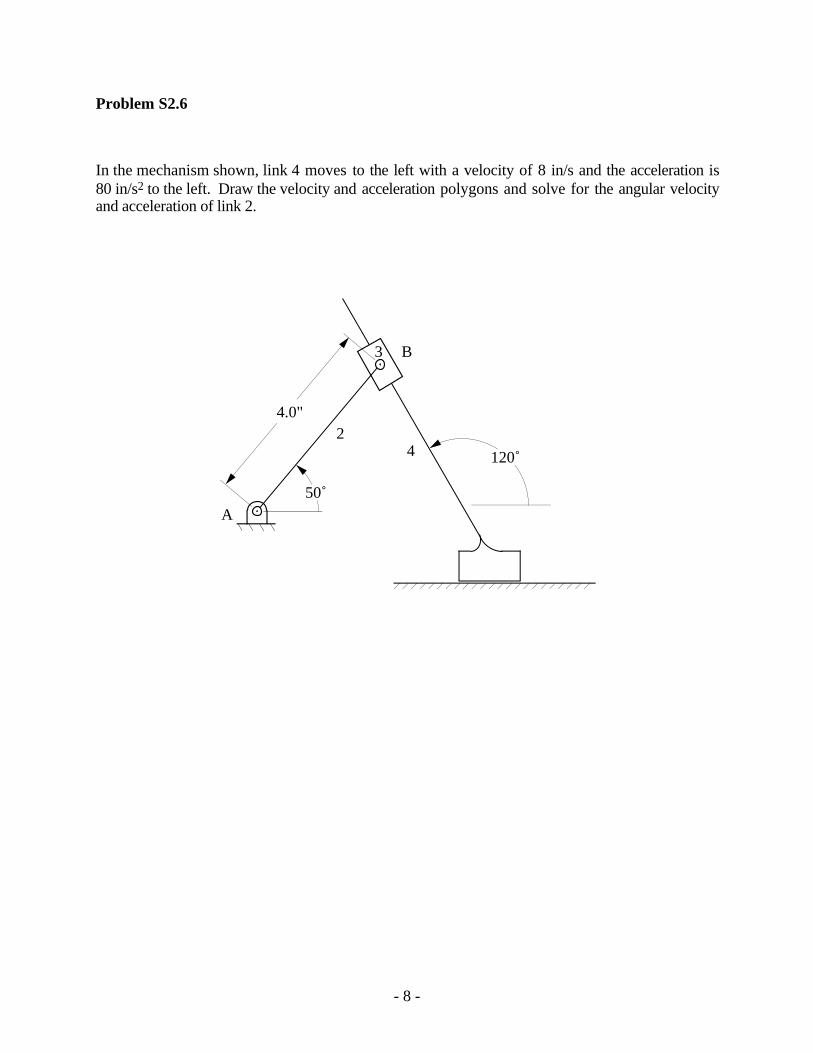
Problem S2.6
In the mechanism shown, link 4 moves to the left with a velocity of 8 in/s and the acceleration is80 in/s2 to the left. Draw the velocity and acceleration polygons and solve for the angular velocityand acceleration of link 2.
24
A
B3
120˚
50˚
4.0"
- 9 -
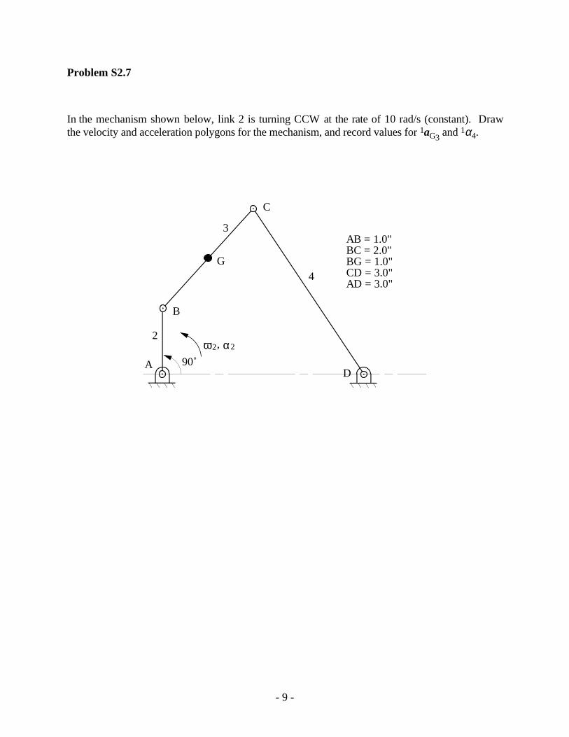
Problem S2.7
In the mechanism shown below, link 2 is turning CCW at the rate of 10 rad/s (constant). Drawthe velocity and acceleration polygons for the mechanism, and record values for 1aG3 and 1α4.
2
3
4
A
C
B
D
G
αω2 2,
90˚
AB = 1.0"BC = 2.0"BG = 1.0"CD = 3.0"AD = 3.0"
- 10 -
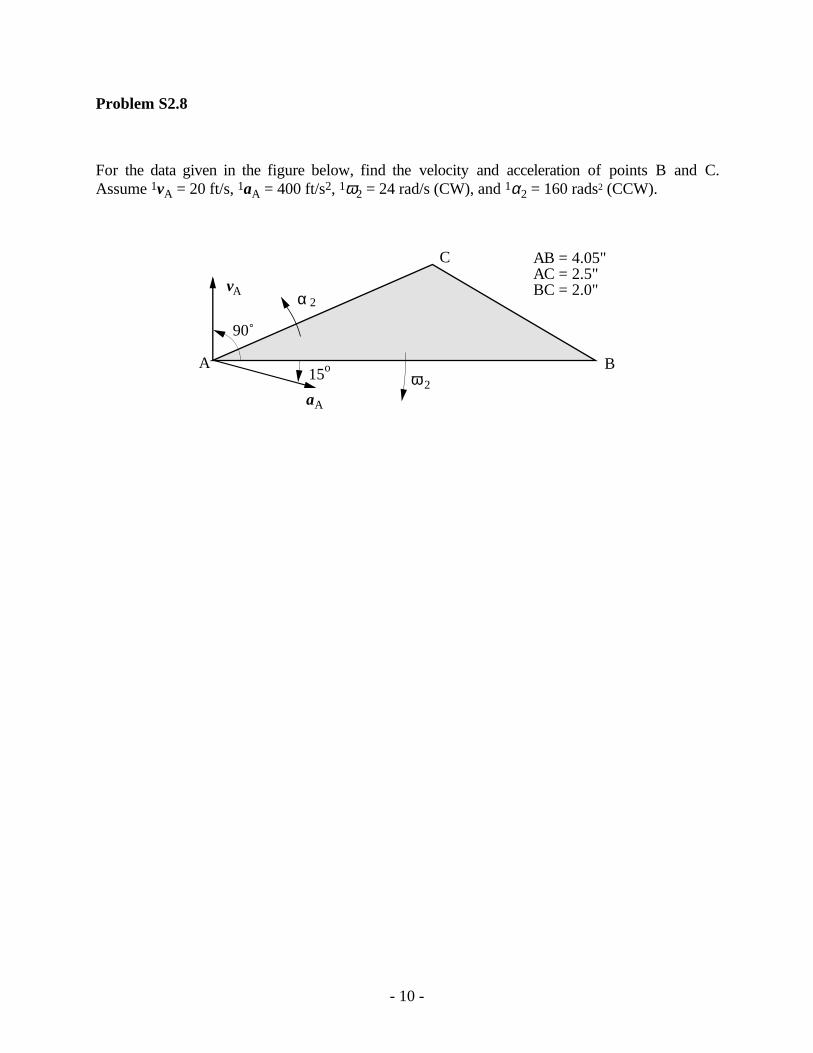
Problem S2.8
For the data given in the figure below, find the velocity and acceleration of points B and C.Assume 1vA = 20 ft/s, 1aA = 400 ft/s2, 1ω2 = 24 rad/s (CW), and 1α2 = 160 rads2 (CCW).
Bω 2
15o
vA
aA
α 2
A
C
90˚
AB = 4.05"AC = 2.5"BC = 2.0"

- 11 -
Problem S2.9
In the mechanism shown, find 1ω6 and 1α3. Also, determine the acceleration of D3 by image.
AC
B
D
E
F (-1.0", -0.75")
2
34
5
6
v = 10 in/sA2 (constant)
X
Y
81˚
CD = 1.0"BD = 1.05"BC = 1.45"ED = 1.5"FE = 1.4"AB = 3.0"

- 12 -
Problem S2.10
In the mechanism shown, 1ω2 = 1 rad/s (CCW) and 1α2 = 0 rad/s2. Find 1ω5, 1α5, 1vE6, 1aE6 forthe position given. Also find the point in link 5 that has zero acceleration for the position given.
A
C
B
D
2
3
4E 5
6
30˚
AD = 1mAB = 0.5mBC = 0.8mCD = 0.8mBE = 0.67m
0.52 m

- 13 -
Problem S2.11
Part of an eight-link mechanism is shown in the figure. Links 7 and 8 are drawn to scale, and thevelocity and acceleration of point D7 are given. Find 1ω7 and 1α7 for the position given. Also findthe velocity of G7 by image.
D
E
7
6
G 8
X
Y
1.25"1.6"
DE = 1.5"DG = 0.7"GE = 1.65"
= 5.0 320˚ in/sec = 40 260˚ in/s 2vD7 aD7

- 14 -
Problem S2.12
In the figure shown below, points A, B, and C are collinear. If 1vA2 = 10 in/s (constant)
downward, find 1vC3, and 1aC3.
A
B
2
3
Cam Contact
Rolling Contact
C
1"
0.35"
45˚
0.45"

- 15 -
Problem S2.13
Part of an eight-link mechanism is shown in the figure. There is rolling contact at location B.Links 7 and 8 are drawn to scale, and the velocity and acceleration of points A6 and C5 are asshown. Find 1ω8 and 1α7 for the position given. Also find the velocity of E7 by image.
A
B
C
78
D
6 5
E
72˚
AD = 2.25"DB = 1.0"AC = 2.85"
vC5 = 10 0˚ in/s
vA6 = 10 60˚ in/s
aC5 = 20 270˚ in/s 2
aA6 = 20 180˚ in/s 2

- 16 -
Problem S2.14
In the position shown, find the velocity and acceleration of link 3 using (1) equivalent linkages and(2) direct approach.
1ω 2 A
B
C2
3
1ω 2= 100 rad/ s CCW
1α 2= 20,000 rad /s 2 CCW
45˚
ΑΒ = 0.5"BC = 1.1"

- 17 -
Problem S2.15
For the mechanism shown, find 1ω3, 1α3, 1aB3, and the location of the center of curvature of the
path that point B3 traces on link 2.
, α 21ω21
A
B
C
D
2
12"
3117˚
AC = 9 inAB = 2 in 1α2 = 0
1ω2 = 50 rad/s
- 18 -
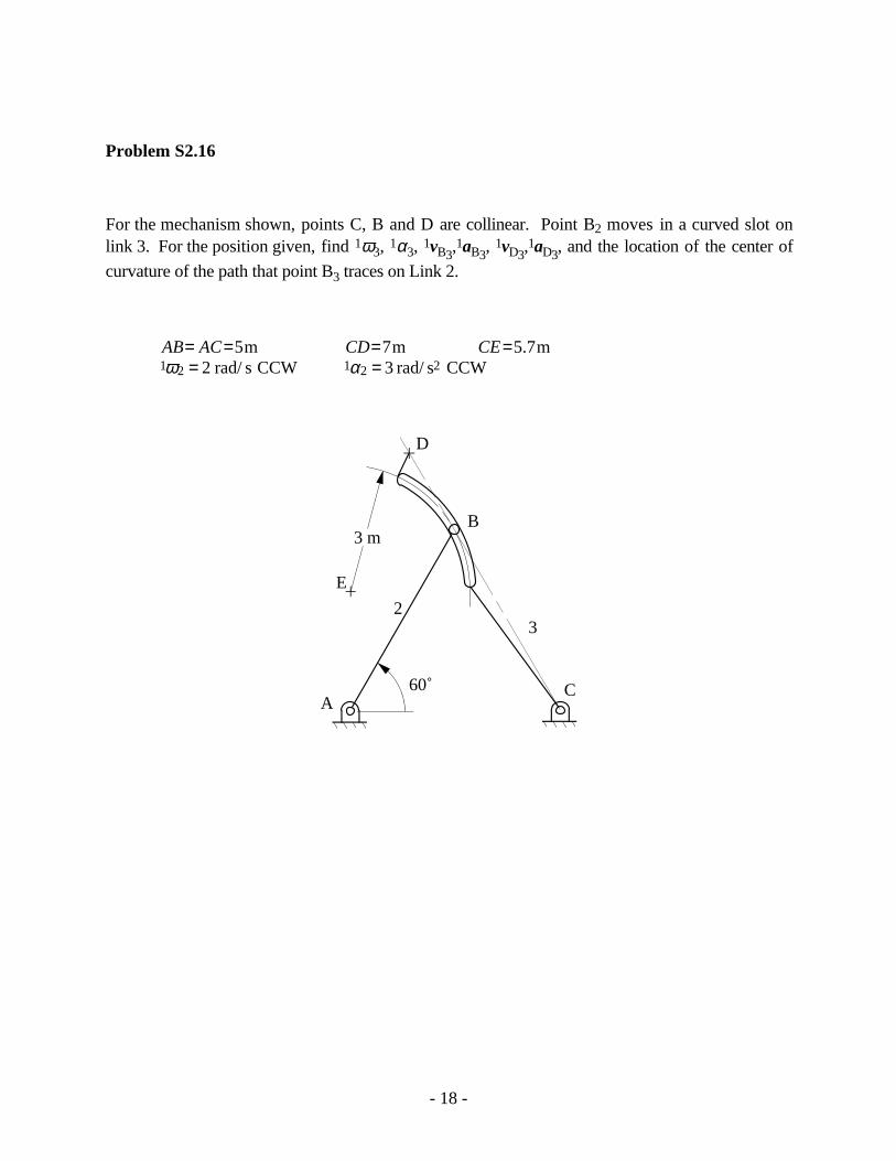
Problem S2.16
For the mechanism shown, points C, B and D are collinear. Point B2 moves in a curved slot onlink 3. For the position given, find 1ω3, 1α3, 1vB3,
1aB3, 1vD3,
1aD3, and the location of the center of
curvature of the path that point B3 traces on Link 2.
AB AC CD CE= = = == =
5 7 5 72 31 2 1 2
m m . mrad/ s CCW rad/ s CCW2ω α
CA
23
60˚
D
B
E
3 m
- 19 -
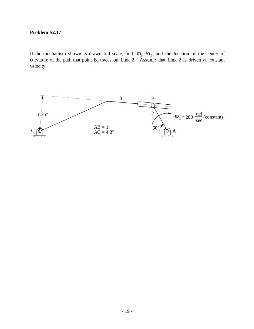
Problem S2.17
If the mechanism shown is drawn full scale, find 1ω3, 1α3, and the location of the center ofcurvature of the path that point B3 traces on Link 2. Assume that Link 2 is driven at constantvelocity.
sec2
3
AC
B
1ω2 = 200rad
(constant)
AB = 1"AC = 4.3"
60˚
1.25"

- 20 -
Problem S2.18
In the mechanism below, the angular velocity of Link 2 is 2 rad/s CCW and the angularacceleration is 5 rad/s2 CW. Determine the following: v v a aB D B D4 4 4 44 4, , , , , ,ωω αα and the centerof curvature of the path that B4 traces on Link 2.
A
B
C
D
2
3
4
12ω
1 2α
75˚
AC = 5.2 inAB = 6.0 inCD = 10.0 in
Problem S2.19
Resolve Problem S2.18 if 1ω2 = 2 rad/sec (constant)

- 21 -
Problem S2.20
If 1ω2 = 20 rad/s (constant), find 1ω3, 1α3, and the center of curvature of the path that C3 traces onLink 2.
A
C
B
D
Pin in Slot
2
3
Center of curvature of slot
12ω
R
X
Y
CD = 0.6"AD = 4.0"R = 1.35"AB = 3.22"
102˚

- 22 -
Problem S2.21
In the mechanism below, 1ω2 = 10 rad/s. Complete the velocity polygon, and determine thefollowing: 1vD4, 1ω4, 1vF6, 1ω6.
C
A
B
DE
F
2
4
3
5
6
G (-5.6, 2.65)
X
Y
AB = 1.0 inBD = 4.3 inAE = 3.0 inDE = 4.0 inGF = 3.35 inBC = 3.4 in
75˚
100˚
- 23 -
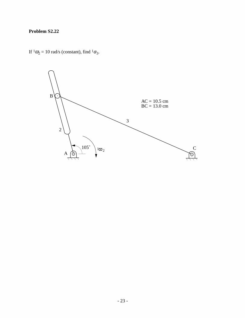
Problem S2.22
If 1ω2 = 10 rad/s (constant), find 1α3.
2
3
AC
B
ω1 2105˚
AC = 10.5 cmBC = 13.0 cm

- 24 -
Problem S2.23
If 1ω2 = 10 rad/s CW (constant), find
a) 1ω3
b) The center of curvature of the path that B2 traces on link 3 (show on drawing).
c) The center of curvature of the path that B3 traces on link 2 (show on drawing).
B
2
3A C40˚
AB = 2"AC = 4"

- 25 -
Problem S2.24
Determine the velocity and acceleration of point B on link 2.
2
3
1ω 4= 1 rad/s
1α 4= 0
A
B
4
X
Y
10 in
30˚
- 26 -
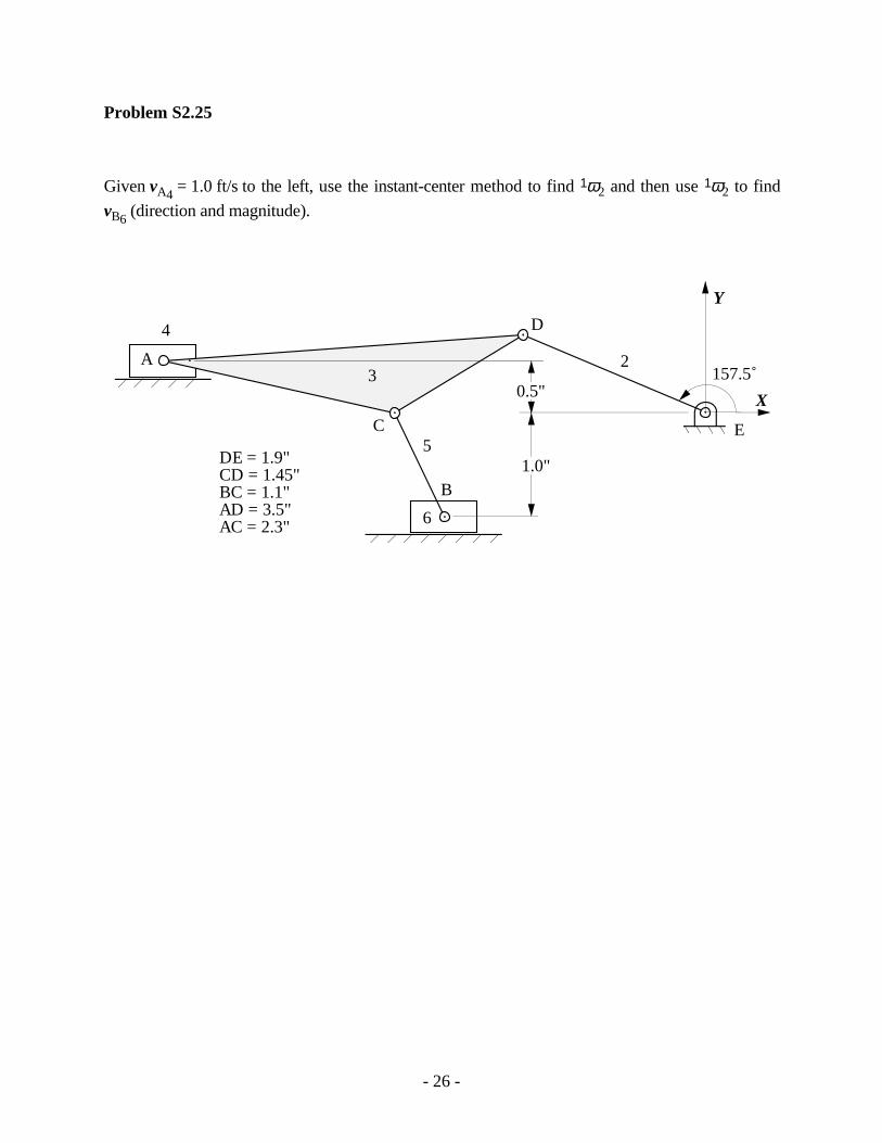
Problem S2.25
Given vA4 = 1.0 ft/s to the left, use the instant-center method to find 1ω2 and then use 1ω2 to find
vB6 (direction and magnitude).
A
B
C
D
2
4
5E
6
3
X
Y
157.5˚
DE = 1.9"CD = 1.45"BC = 1.1"AD = 3.5"AC = 2.3"
1.0"
0.5"
- 27 -
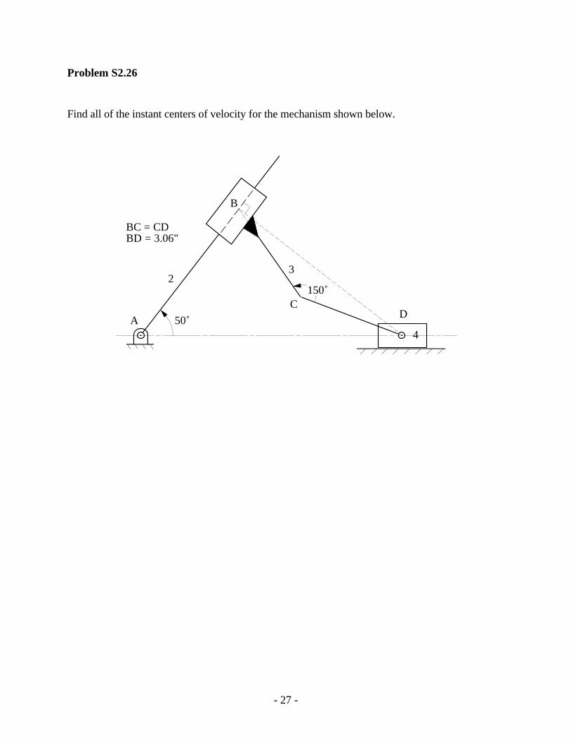
Problem S2.26
Find all of the instant centers of velocity for the mechanism shown below.
23
4A
B
CD
50˚
150˚
BC = CDBD = 3.06"

- 28 -
Problem S2.27
If the velocity of point A on link 2 is 10 in/s as shown, use the instant center method to find thevelocity of point C on link 5.
2
3
4
6
A5C
B
5
vA
D E
F (3.15", 1.9")
G
5
X
Y
75˚
DE = 2.5"AD = 0.75"AB = 1.75"BE = 1.5"GF = 1.5"
0.45"
0.25"

- 29 -
Problem S2.28
Assume that link 7 rolls on link 3 without slipping, and find the following instant centers: I13, I15,and I27. For the given value for 1ω2, find 1ω7 using instant centers.
1ω 2 = 2 rad/s
2
34
5
6
7
X
Y
A
BC
D
E
G
F (-2.0", 0.95")
AB = 1.8"BG = 0.85"GF = 1.7"BD = 3.9"DE = 3.25"AE = 2.0"
1.0"0.75"
90˚

- 30 -
Problem S2.29
If 1vA2 = 10 cm/s as shown, find 1vC5 using the instant-center method.
24
A3 5
B
1v 2
6C
A
D
E
F
G
DA = 0.95"DF = 2.45"AB = 1.45"BF = 1.8"
BE = 0.85"EG = 2.2"EC = 1.2"CG = 1.25"
1.9"
70˚

- 31 -
Problem S2.30
If 1ω2 = 10 rad/s CCW, find the velocity of point B using the instant-center method. Show thevelocity vector 1vB3 on the figure.
1ω2
ΑΒ
2
3 4
E
C D45˚
18˚
110˚
CA = 1.5"DE = 2.5"CD = 4.0"AB = 1.6"
- 32 -
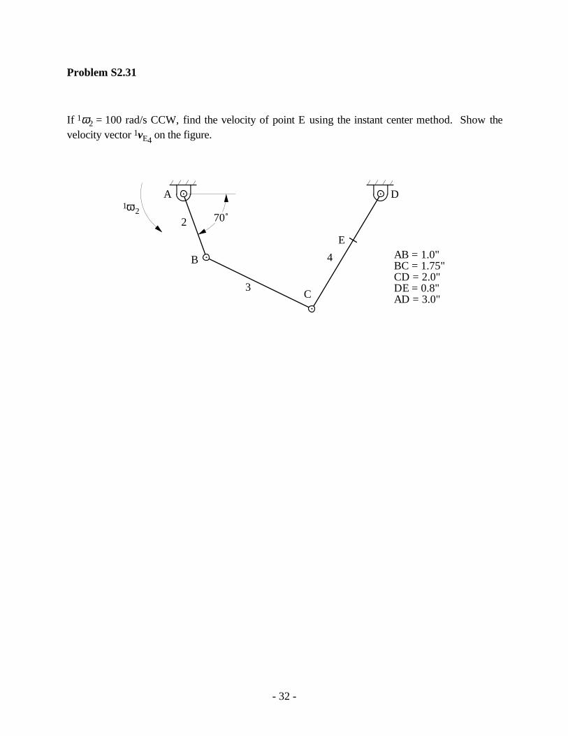
Problem S2.31
If 1ω2 = 100 rad/s CCW, find the velocity of point E using the instant center method. Show thevelocity vector 1vE4 on the figure.
A
C
AB = 1.0"BC = 1.75"CD = 2.0"DE = 0.8"AD = 3.0"
1ω2
B
D
E
70˚2
3
4

- 33 -
Problem S2.32
In the linkage shown below, locate all of the instant centers.
2
3
4
5
6
55˚
AB = 1.35"BD = 3.9"DE = 0.9"BC = 0.9"CF = 2.0"
A
B
C
D
E
F
3.3"
- 34 -
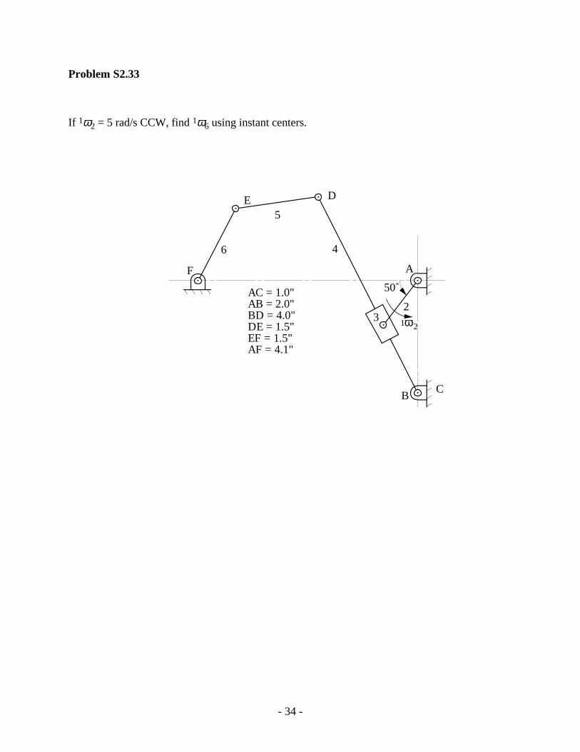
Problem S2.33
If 1ω2 = 5 rad/s CCW, find 1ω6 using instant centers.
C
DE
21ω2
4
5
6
50˚
A
B
F
AC = 1.0"AB = 2.0"BD = 4.0"DE = 1.5"EF = 1.5"AF = 4.1"
3

- 35 -
Problem S2.34
If 1ω2 = 100 rad/s CCW, find 1vB4 using instant centers and the rotating radius method.
A
B
2
3
4
C
D
4
95˚
G
EF
AD = 1.8"CD = 0.75"AE = 0.7"CF = 0.45"FG = 1.75"CB = 1.0"DB = 1.65"
125˚

- 36 -
Problem S2.35
If 1vA2 = 10 in/s as shown, find the angular velocity (1ω6) of link 6 using the instant-center
method.
23
4
56
A
1v2A
27˚
AB = 1.0"AD = 2.0"AC = 0.95"CE = 2.0"EF = 1.25"BF = 3.85"
BC
D
E
F

- 37 -
Problem S2.36
If 1ω2 = 50 rad/s CCW, find the velocity of point G using the instant center method. Show thevelocity vector 1vG5 on the figure.
AB = 1.16"BC = 0.70"CD = 1.45"DE = 1.16"AD = 1.30"DF = 1.30EG = 2.20"
1ω 2
A
C
B
D F
75˚2
3
4
G
E
32˚ 5
6

- 38 -
Problem S2.37
If 1ω2 = 100 rad/s CCW, find 1ω6.
2
34
A
C
E (2.0", 6.0")
Y
BD
F
X
5
6
1 2ω
AB = 1.2"BC = 6.0"CD = 3.0"AD = 4.0"BF = 3.0"

- 39 -
Supplemental Exercise Problems for Chapter 3
Problem 3.1
For the mechanism shown, write the loop equations for position, velocity, and acceleration. Showall angles and vectors used on the drawing and identify all variables. For the position defined bythe data below, find 1 4vC and 1 4aC if link 2 rotates with constant angular velocity.
AB BC= = = ° =1 4 90 1cm, cm, , ˙ rad/ sθ θ
A
B
2C
3
4θ
Problem 3.2
In the mechanism shown, φ is 10 rad/s CCW. Use the loop equation approach to determine thevelocity of point B4 for the position defined by φ = 60˚.
34
φ
2 10 inches
B
Problem 3.3
In the mechanism given, 1vB2 is 10 in/s to the right (constant). Use the loop equation approach to
determine 1vA4 and 1aA4. Use point O as the origin of your coordinate system.
30˚
A
B
2
3
4
1vB2
AB = 10 inches
O

- 40 -
Problem 3.4
In the mechanism shown, Link 3 slides on link 2, and link 4 is pinned to link 3. Link 4 also slideson the frame (link 1). If 1ω2 = 10 rad/s CCW, use the loop-equation approach to determine thevelocity of link 4 for the position defined by φ = 45˚.
3
φ
210 inches
4
A
B
Problem 3.5
Use loop equations to determine the velocity and acceleration of point B on link 4.
2
3
1ω 2=1 radsec
1α 2 = 0
B 4 x
y3 in
A
30˚
Problem 3.6
Use loop equations to determine the angular velocity and acceleration of link 3 if vB4 is a constant
10 in/s to the left and 1θ3 is 30˚.
2
3
x
y3 in
A
B 4
θ1 3B4v

- 41 -
Problem 3.7
The shock absorber mechanism on a mountain bicycle is a four-bar linkage as shown. The frameof the bike is link 1, the fork and tire assembly is link 3, and the connecting linkage are links 2 and4. As the bicycle goes over a bump in the position shown, the angular velocity of link 2 relative tothe frame is 1 2ωω is 205 (rad/s), and the angular acceleration is 1 2αα is 60 (rad/s2), both in theclockwise direction. Compute the angular velocity and angular acceleration of link 3 for theposition shown
2
4
1
3
A
D
C
B
1.88"
2.22"
201˚
1.55"
1.64"
1 2ω61˚
Problem 3.8
The purpose of this mechanism is to close the hatch easily and also have it remain in an openposition while the owner removes items from the back. This is done by the use of an air cylinder,which helps to support the hatch while it closes and holds it up in the open position. Themechanism is an inverted slider-crank linkage, where the car acts as the base link. There are twoidentical linkages one on each side of the car. Assume that the angular velocity of the driver (link2) is a constant 0.82 rad/s clockwise and the angular acceleration is 0. Compute the linear velocityof point D2, and the angular velocity and angular acceleration of link 3 for the position shown
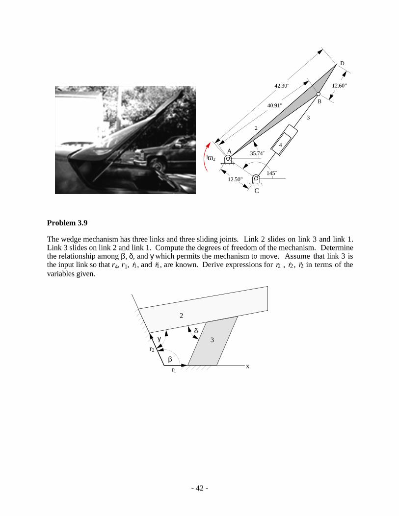
- 42 -
1 2ω
C
A
12.50"
B
D
12.60"42.30"
40.91"
2
3
4
145˚
35.74˚
4
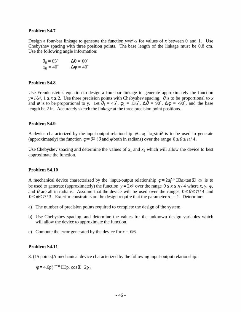
Problem 3.9
The wedge mechanism has three links and three sliding joints. Link 2 slides on link 3 and link 1.Link 3 slides on link 2 and link 1. Compute the degrees of freedom of the mechanism. Determinethe relationship among β, δ, and γ which permits the mechanism to move. Assume that link 3 isthe input link so that r4, r1, r1, and ˙r1, are known. Derive expressions for r2 , r2 , ˙r2 in terms of thevariables given.
β
γδ
x
2
3
r1
r2

- 43 -
Supplemental Exercise Problems for Chapter 4
Problem S4.1
Design a four-bar linkage to move a coupler containing the line AB through the three positionsshown. The moving pivot (circle point) of one crank is at A and the fixed pivot (center point) ofthe other crank is at C*. Draw the linkage in position 1, and use Grashof’s equation to identify thetype of four-bar linkage designed. Position A1B1 is horizontal, and positions A2B2 and A3B3 arevertical. AB = 6 cm.
A1B1
B3
C*
A3 (-2, 3)(6, 4.3)
X
Y
(0, 0)
B2
A2 (2, 3)
Problem S4.2
Design a four-bar linkage to move its coupler through the three positions shown below usingpoints A and B as moving pivots. AB = 4 cm. What is the Grashof type of the linkage generated?
B1
B2
B3
X
Y
60˚
50˚
A1(0, 0)
A2(2, 0.85)
A3(2, 2.4)

- 44 -
Problem S4.3
Synthesize a four-bar mechanism in position 2 that moves its coupler through the three positionsshown below if points C* and D* are center points. Position A1B1 and position A3B3 arehorizontal. AB = 4 cm.
B
B
B
A11
A2
2
A33
C*
D*
X
Y
(0.7, - 1.8)
(3.0, 2.6)
(2.7, - 0.7)
(3.4, 1.6)
45˚
Problem S4.4
Synthesize a four-bar mechanism in position 2 that moves its coupler through the three positionsshown below. Point A is a circle point, and point C* is a center point. Position A1B1 and positionA3B3 are horizontal. AB = 4 cm.
B
B
A1 B1
A2
2
A33
C*
(2.0, 1.0)
(2.7, 3.5)
(2.3, 4.5)
X
Y
45˚

- 45 -
Problem S4.5
Design a four-bar linkage to move the coupler containing line segment AB through the threepositions shown. The moving pivot for one crank is to be at A, and the fixed pivot for the othercrank is to be at C*. Draw the linkage in position 1 and determine the classification of the resultinglinkage (e.g., crank rocker, double crank). Positions A1B1 and A2B2 are horizontal, and positionA3B3 is vertical. AB = 2.0 in.
A2
C*
B3
A1
A3
(-0.5, -2.0)
B2 (0.0, 1.5)
X
Y
B1(-1.0, 0.5)
Problem S4.6
Design a four-bar linkage to move a coupler containing the line AB through the three positionsshown. The moving pivot (circle point) of one crank is at A and the fixed pivot (center point) ofthe other crank is at C*. Draw the linkage in position 2 and use Grashof’s equation to identify thetype of four-bar linkage designed. Position A1B1 is horizontal, and positions A2B2 and A3B3 arevertical. AB = 4 in.
A1 B1
B 2
A2
B3
A3
X
Y
(2, 0) (4, 0)
(0, 2)
C1* (0, 0)
- 46 -
Problem S4.7
Design a four-bar linkage to generate the function y=ex-x for values of x between 0 and 1. UseChebyshev spacing with three position points. The base length of the linkage must be 0.8 cm.Use the following angle information:
θ0 = 65˚ ∆θ = 60˚φ0 = 40˚ ∆φ = 40˚
Problem S4.8
Use Freudenstein's equation to design a four-bar linkage to generate approximately the functiony=1/x2, 1 ≤ x ≤ 2. Use three precision points with Chebyshev spacing. θ is to be proportional to xand φ is to be proportional to y. Let θ1 = 45˚, φ1 = 135˚, ∆θ = 90˚, ∆φ = -90˚, and the baselength be 2 in. Accurately sketch the linkage at the three precision point positions.
Problem S4.9
A device characterized by the input-output relationship φ θ= +x x1 2sin is to be used to generate(approximately) the function φ θ= 2 (θ and φ both in radians) over the range 0 4≤ ≤θ π / .
Use Chebyshev spacing and determine the values of x1 and x2 which will allow the device to bestapproximate the function.
Problem S4.10
A mechanical device characterized by the input-output relationship φ θ= + +2 312 8 2 3a a a. tan is to
be used to generate (approximately) the function y x= 2 3 over the range 0 4≤ ≤x π / where x, y, φ,and θ are all in radians. Assume that the device will be used over the ranges 0 4≤ ≤θ π / and0 3≤ ≤φ π / . Exterior constraints on the design require that the parameter a1 = 1. Determine:
a) The number of precision points required to complete the design of the system.
b) Use Chebyshev spacing, and determine the values for the unknown design variables whichwill allow the device to approximate the function.
c) Compute the error generated by the device for x = π/6.
Problem S4.11
3. (15 points)A mechanical device characterized by the following input-output relationship:
φ θπ= + +4 6 3 212 7 2 3. cos. *p p p
- 47 -
is to be used to generate (approximately) the function y x= 2 over the range 04
≤ ≤x π where
x, y, φ, and θ are all in radians. Assume that the device will be used over the ranges
03
≤ ≤θ π and 03
≤ ≤φ π . The problem is such that you may pick any value for any one of the
design variables and solve for the other two; i.e., pick a value for one of p1, p2, p3 and solve forthe other two.
Determine:
1) The number of precision points required to complete the design of the system.
2) Use Chebyshev spacing, and determine the values for the unknown design variables whichwill allow the device to approximate the function.
3) Compute the error generated by the device for x = π/6.
Problem S4.12
Design a crank-rocker mechanism such that with the crank turning at constant speed, theoscillating lever will have a time ratio of advance to return of 3:2. The lever is to oscillate throughan angle of 80o, and the length of the base link is to be 2 in.
Problem S4.13
Design a crank-rocker mechanism which has a base length of 1.0, a time ratio of 1.25, and arocker oscillation angle of 40˚. The oscillation is to be symmetric about a vertical line through O4.Specify the length of each of the links.
- 48 -
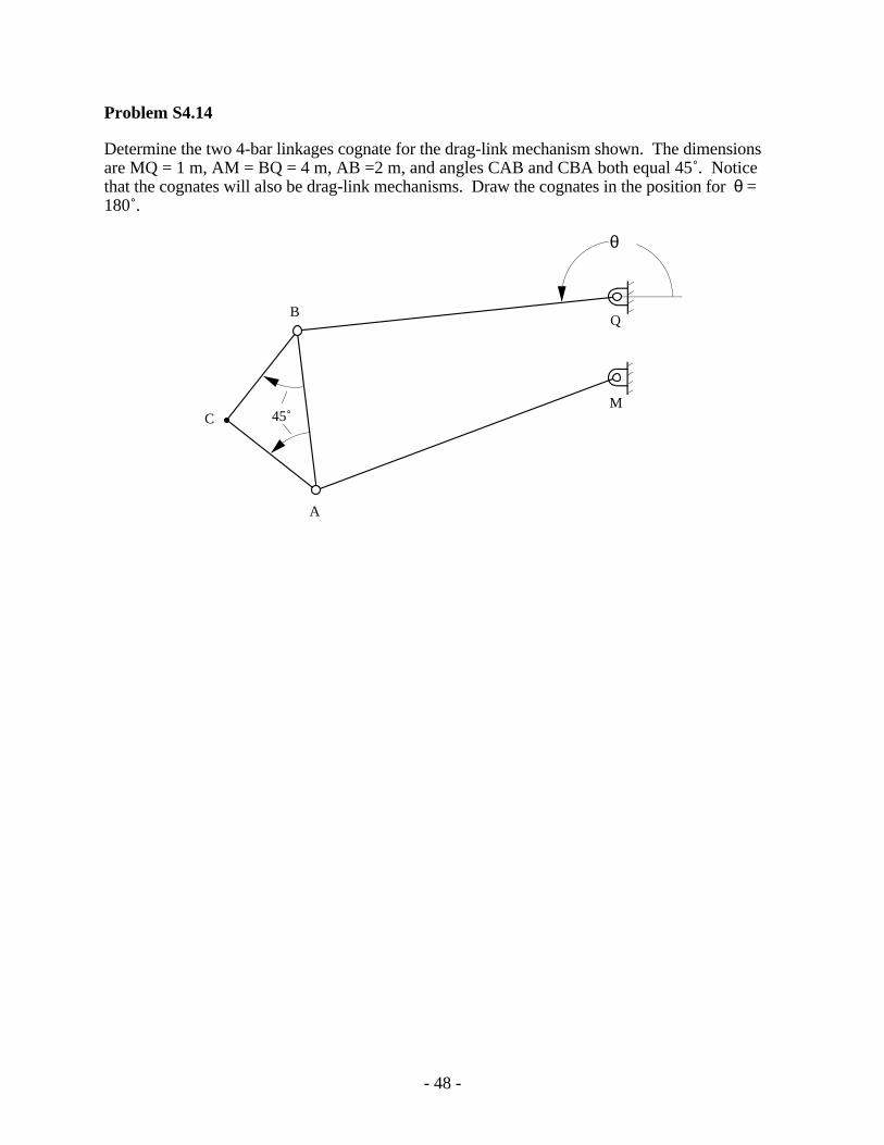
Problem S4.14
Determine the two 4-bar linkages cognate for the drag-link mechanism shown. The dimensionsare MQ = 1 m, AM = BQ = 4 m, AB =2 m, and angles CAB and CBA both equal 45˚. Noticethat the cognates will also be drag-link mechanisms. Draw the cognates in the position for θ =180˚.
M
Q
A
B
C 45˚
θ
- 49 -
Supplemental Exercise Problems for Chapter 5
No supplemental problems were developed for Chapter 5.
Supplemental Exercise Problems for Chapter 6
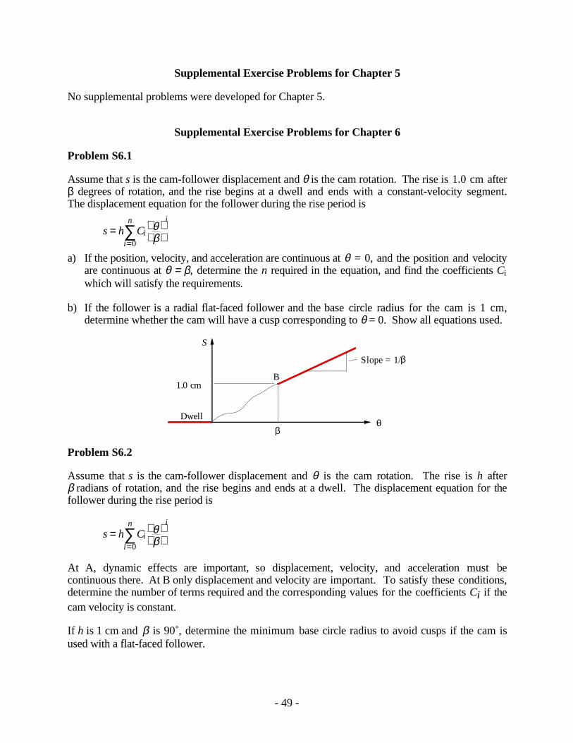
Problem S6.1
Assume that s is the cam-follower displacement and θ is the cam rotation. The rise is 1.0 cm afterβ degrees of rotation, and the rise begins at a dwell and ends with a constant-velocity segment.The displacement equation for the follower during the rise period is
s h Ci
i
i
n=
=
∑ θβ0
a) If the position, velocity, and acceleration are continuous at θ = 0, and the position and velocityare continuous at θ = β, determine the n required in the equation, and find the coefficients Ciwhich will satisfy the requirements.
b) If the follower is a radial flat-faced follower and the base circle radius for the cam is 1 cm,determine whether the cam will have a cusp corresponding to θ = 0. Show all equations used.
S
θβ
Dwell
Slope = 1/β
B1.0 cm
Problem S6.2
Assume that s is the cam-follower displacement and θ is the cam rotation. The rise is h afterβ radians of rotation, and the rise begins and ends at a dwell. The displacement equation for thefollower during the rise period is
s h Ci
i
i
n=
=
∑ θβ0
At A, dynamic effects are important, so displacement, velocity, and acceleration must becontinuous there. At B only displacement and velocity are important. To satisfy these conditions,determine the number of terms required and the corresponding values for the coefficients Ci if thecam velocity is constant.
If h is 1 cm and β is 90˚, determine the minimum base circle radius to avoid cusps if the cam isused with a flat-faced follower.

- 50 -
S
h
Dwell
Α β
Β
θ , rad
Dwell
Problem S6.3
Resolve Problem 6.12 if the cam velocity is 2 rad/s constant. Note: Use the minimum number ofCi possible. If h is 3 cm and β is 60˚, determine the minimum base circle radius to avoid cusps ifthe cam is used with a flat-faced follower.
Problem S6.4
For the cam displacement schedule given, h is the rise, β is the angle through which the rise takesplace, and s is the displacement at any given angle θ. The displacement equation for the followerduring the rise period is
s h ai
i
i
=
=
∑ θβ0
5
Determine the required values for a0 ... a5 such that the displacement, velocity, and accelerationfunctions are continuous at the end points of the rise portion.
If h is 1 cm and β π= / 3, determine the minimum base circle radius to avoid cusps if the cam isused with a flat-faced follower.
S
h
Dwell
Α β
Β
θ , rad
Dwell
Problem S6.5
Resolve Problem 6.14 if the cam will be used for a low-speed application so that accelerationeffects can be neglected. Determine the number of terms required and the corresponding valuesfor the constants (Ci) if the displacement and velocity are continuous at the end points of the rise(points A and B) and if the cam velocity is constant.
If h is 1 cm and β is 90˚, determine the minimum base circle radius to avoid cusps if the cam isused with a flat-faced follower.

- 51 -
Problem S6.6
Lay out a cam profile using a harmonic follower displacement profile for both the rise and return.The cam is to have a translating, flat-faced follower which is offset in the clockwise direction by0.2 in. Assume that the follower is to dwell at zero lift for the first 100˚ of the motion cycle and todwell at 1 in lift for cam angles from 220˚ to 240˚. The cam will rotate clockwise, and the basecircle radius is to be 2 in. Lay out the cam profile using 20˚ plotting intervals.
- 52 -
Supplemental Exercise Problems for Chapter 7
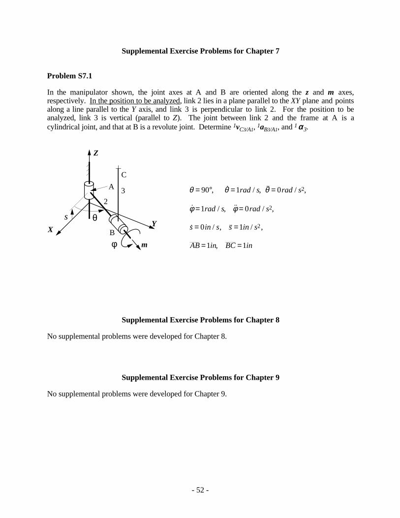
Problem S7.1
In the manipulator shown, the joint axes at A and B are oriented along the z and m axes,respectively. In the position to be analyzed , link 2 lies in a plane parallel to the XY plane and pointsalong a line parallel to the Y axis, and link 3 is perpendicular to link 2. For the position to beanalyzed, link 3 is vertical (parallel to Z). The joint between link 2 and the frame at A is acylindrical joint, and that at B is a revolute joint. Determine 1vC3/A1, 1aB3/A1, and 1αα3.
θ
C
B
23A
mφX
Y
Z
s
θ θ θ
φ φ
= ° = =
= =
= =
= =
90 1 0
1 0
0 1
1 1
2
2
2
, ˙ / , ˙ / ,
˙ / , ˙ / ,
˙ / , ˙ / ,
,
rad s rad s
rad s rad s
s in s s in s
AB in BC in
Supplemental Exercise Problems for Chapter 8
No supplemental problems were developed for Chapter 8.
Supplemental Exercise Problems for Chapter 9
No supplemental problems were developed for Chapter 9.

- 53 -
Supplemental Exercise Problems for Chapter 10
Problem S10.1
An alternative gear train is shown as a candidate for the spindle drive of a gear hobbing machine.The gear blank and the worm gear (gear 9) are mounted on the same shaft and rotate together. Ifthe gear blank is to be driven clockwise, determine the hand of the hob. Next determine thevelocity ratio (ω ω3 5/ ) to cut 75 teeth on the gear blank. Finally, select gears 3 and 5 which willsatisfy the ratio. Gears are available which have all of the tooth numbers from 15 to 40.
To motor
Gear blank5
6
7
3Idler Gear
4
(180T)
9
2
Hob (1T)
(35T)
105T
Right-Handed Single Tooth Worm
Problem S10.2
A simple gear reduction unit is to be used to generate the gear ratio 2.105399. Make up a table ofpossible gear ratios where the maximum number of teeth on all gears is 100. Identify the gear setthat most closely approximates the desired ratio. Note that this can be done most easily with acomputer program. What is the error?
Problem S10.3
Resolve Problem 10.20 when N2 = 80T, N3 = 30T, N4 = 20T and N5 = 130.
- 54 -
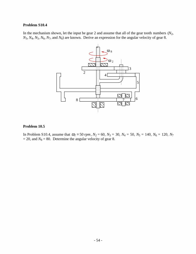
Problem S10.4
In the mechanism shown, let the input be gear 2 and assume that all of the gear tooth numbers (N2,N3, N4, N5, N6, N7, and N8) are known. Derive an expression for the angular velocity of gear 8.
AAAAAAAA
ω 8
ω 2
AAAA
AAAA
7AAAA
AAAA
AAAA
AAAA
4
3
5
6
2
8
Problem 10.5
In Problem S10.4, assume that ω2 50= rpm , N2 = 60, N3 = 30, N4 = 50, N5 = 140, N6 = 120, N7= 20, and N8 = 80. Determine the angular velocity of gear 8.
- 55 -
Supplemental Exercise Problems for Chapter 11
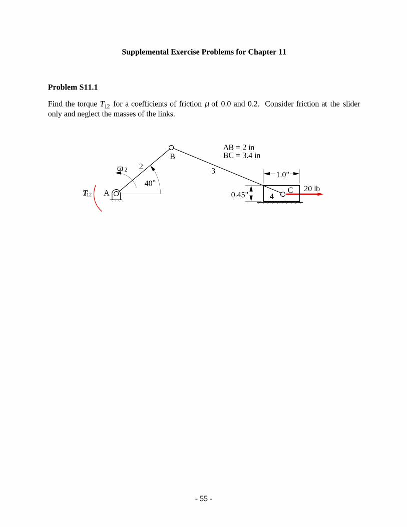
Problem S11.1
Find the torque T12 for a coefficients of friction µ of 0.0 and 0.2. Consider friction at the slideronly and neglect the masses of the links.
20 lbA
ω 2
B
4
32
C40˚
T12
AB = 2 inBC = 3.4 in
1.0"
0.45"
- 56 -
Supplemental Exercise Problems for Chapter 12
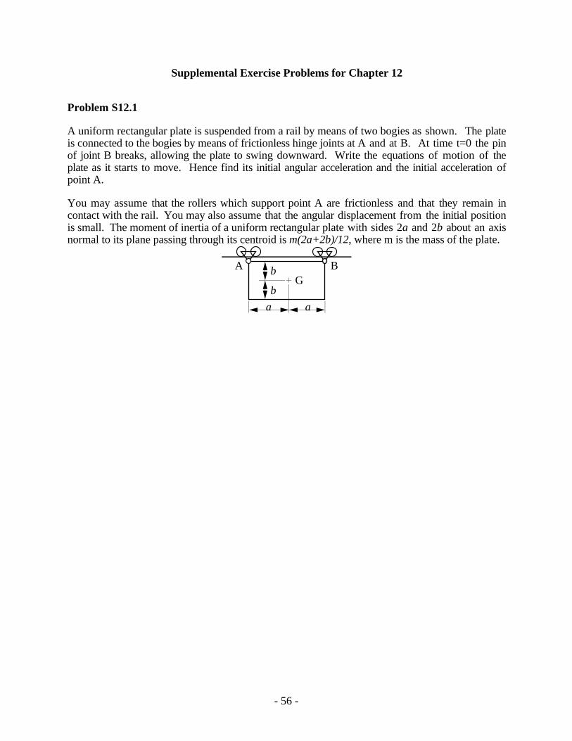
Problem S12.1
A uniform rectangular plate is suspended from a rail by means of two bogies as shown. The plateis connected to the bogies by means of frictionless hinge joints at A and at B. At time t=0 the pinof joint B breaks, allowing the plate to swing downward. Write the equations of motion of theplate as it starts to move. Hence find its initial angular acceleration and the initial acceleration ofpoint A.
You may assume that the rollers which support point A are frictionless and that they remain incontact with the rail. You may also assume that the angular displacement from the initial positionis small. The moment of inertia of a uniform rectangular plate with sides 2a and 2b about an axisnormal to its plane passing through its centroid is m(2a+2b)/12, where m is the mass of the plate.
A BG
a a
b
b

- 57 -
Supplemental Exercise Problems for Chapter 13
Problem S13.1
For the mechanism and data given, determine the shaking force and its location relative to point A.Draw the shaking force vector on the figure.
1ω2= 210 rad/s CCW 1α2= rad/s2 W2 = 3.40 lb
IG3= 0.1085 lb-s2-in W3= 3.40 lb W4= 2.85 lb
B
G2
G3
3
G4
A4
CAB = 3 inBC = 12 inBG = 6 in3
45˚
Problem S13.2
For the engine given in Problem 13.11, lump the weight of the connecting rod at the crank pin andpiston pin and locate the counterbalancing weight at the crank radius. Determine the optimumcounter balancing weight which will give
1. The smallest horizontal shaking force
2. The smallest vertical shaking force
Problem S13.3
Resolve Problem 13.16 for the following values for the phase angles and offset distances.
φ φ φ φ1 2 3 4
1 2 3 4
0 180 90 2700 2 3
= = = == = = =
˚ ˚ ˚a a a a a a a
Problem S13.4
The four-cylinder V engine shown below has identical cranks, connecting rods, and pistons. Therotary masses are perfectly balanced. Derive an expression for the shaking forces and shakingmoments for the angles and offset values indicated. The V angle is ψ = 60˚, and the phase angleis φ2 180= ˚. Are the primary or secondary shaking forces balanced? What about the primary and

- 58 -
secondary shaking moments? Suggest a means for balancing any shaking forces or couples whichresult.
Cyl
inde
rs 1
and
3
Cyl
inde
rs 2
and
4
A2
y
A1
ψφ
2
X
B1
B4
B3B2
θ
L
R
φ 1 = 0
φ 2 = 180˚
a
Problem S13.5
Resolve Problem S13.4 if the V angle is ψ = 90˚. Estimate the optimum value for ψ .
Problem S13.6
Assume that a seven-cylinder in-line engine is being considered for an engine power plant. Theengine is characterized by the following phase angles:
φ φ φ φ φ φ φ1 2 3 4 5 6 70 90 180 180 0 120 240= = = = = = =, ˚, ˚, ˚, ˚, ˚, ˚and
a a a a a a a a a a a a a1 2 3 4 5 6 70 2 3 4 5 6= = = = = = =, , , , , , and
Determine the type of unbalance which exists in the engine.