Kinematic Diagnosis System and · PDF file- Creation of conditions for dealing safely with...
21
VS-23/Friedrich Baugruppe/Group: 32 32 01 99 (503) weltweit all countries 10/1999 Kinematic Diagnosis System and environment BMW KDS (Beissbarth) Table of contents 1. Foreword 1.1 Objectives 1.2 Further development of the BMW Kinematic Diagnosis System 1.3 Technical data 1.4 Scope of delivery 1.5 Accessories required 1.6 Accessories recommended 2. Measuring options using the BMW Kinematic Diagnosis System 2.1 Front axle 2.2 Rear axle 2.3 Other measuring options 3. System description 3.1 BMW Kinematic Diagnosis System 1, based on the Beissbarth ML4000 3.2 Computer 3.3 Graphical tablet 3.4 Equipment cabinet 3.5 Remote display 3.6 Measuring sensors with CCD camera 3.7 BMW Quick-acting clamp SBT Kinematic Diagnosis System and environment BMW KDS (Beissbarth) BMW AG - TIS 28.03.2008 20:41 Issue status (01/2005) Valid only until next CD is issued Copyright Page - 1 -
-
Upload
hoangkhuong -
Category
Documents
-
view
217 -
download
2
Transcript of Kinematic Diagnosis System and · PDF file- Creation of conditions for dealing safely with...

VS-23/Friedrich Baugruppe/Group: 32
32 01 99 (503)
weltweit
all countries
10/1999
Kinematic Diagnosis System and environment
BMW KDS (Beissbarth)
Table of contents
1. Foreword
1.1 Objectives
1.2 Further development of the BMW Kinematic Diagnosis System
1.3 Technical data
1.4 Scope of delivery
1.5 Accessories required
1.6 Accessories recommended
2. Measuring options using the BMW Kinematic Diagnosis System
2.1 Front axle
2.2 Rear axle
2.3 Other measuring options
3. System description
3.1 BMW Kinematic Diagnosis System 1, based on the Beissbarth ML4000
3.2 Computer
3.3 Graphical tablet
3.4 Equipment cabinet
3.5 Remote display
3.6 Measuring sensors with CCD camera
3.7 BMW Quick-acting clamp
SBT Kinematic Diagnosis System and environment BMW KDS (Beissbarth) BMW AG - TIS 28.03.2008 20:41
Issue status (01/2005) Valid only until next CD is issued Copyright Page - 1 -
Timm
Typewritten Text
meeknet.co.uk

3.8 Rotating / sliding plates
3.9 Sensor pins
3.10 Spoiler adapter
3.11 Quick-clamping units
3.12 Retainers
4. Workstation
4.1 Environment
4.2 Preconditions for alignment
4.3 Measuring tolerance
4.4 Levelling the measuring station
5. Chassis-related terms
5.1 Toe-differential angle
5.2 Camber
5.3 Toe-in
5.4 Castor
5.5 Geometrical drive axis / symmetrical axis
5.6 Wheel displacement angle
5.7 Kingpin offset
6. Wheel suspension
6.1 Rigid axle suspension
6.2 Independent wheel suspension
7. Wheel alignment / procedure
7.1 Measuring options
7.2 Preparatory work
7.3 Initial / final measurement
7.4 Printing out the data
8. Special features
8.1 Free wheel alignment
8.2 System settings
9. BMW Kinematic Diagnosis System comparison (Bosch - Beissbarth)
10. Control modification (menu)
10.1 Remote control with display
10.2 Brief operating instructions
10.3 Display support
11. Updating the software / setpoint data
11.1 Requirements
11.2 Procedure (Beissbarth)
11.3 Procedure (Bosch)
12. Creating, copying and editing setpoint data
12.1 Copying
12.2 Creating
12.3 Editing
13. Special functions
13.1 Customer-specific printer report header
SBT Kinematic Diagnosis System and environment BMW KDS (Beissbarth) BMW AG - TIS 28.03.2008 20:41
Issue status (01/2005) Valid only until next CD is issued Copyright Page - 2 -

13.2 Adjusting options
13.3 Rotating plate test
13.4 Viewing and deleting customer entries from database
14. Modifications within program
15. Faults
15.1 Tyre faults
15.2 Front axle faults
15.3 Rear axle faults
1. Foreword
1.1 Objectives
Wheel alignment has become an increasingly complex subject. The aim of this BMW Service Technology bulletin,
therefore, is to achieve several objectives:
- Creation of guidelines for working with the BMW Kinematic Diagnosis System (KDS).
- Familiarisation with wheel alignment technology for current vehicles and clarifying any questions which arise
in this connection.
- Transparency and clarification of different terms.
- Clarification of the causes of errors in the past, such that they can be avoided after reading this document.
- Creation of conditions for dealing safely with the BMW KDS.
1.2 Further development of the BMW Kinematic Diagnosis System
- The BMW Kinematic Diagnosis System is an integrated part of automotive system concepts. It ensures that
work is carried out in a particularly rational manner which is appropriate for BMW requirements, such that youcan also be certain of being prepared for future technolo-
gical developments. As far as precision and performance in wheel alignment and tuning is concerned, BMW,
together with leading manufacturers, has made the best of what is technically feasible: the BMW Kinematic
Diagnosis System.
- The BMW Kinematic Diagnosis System manufactured by Beissbarth is more than just the further
development of conventional wheel alignment equipment. It sets new standards in precision, performance,
speed and handling. It is a guarantor for the perfection which BMW service customers rely on.
- Ride comfort, road safety and tyre wear depend to a large extent on the perfect interplay of the vehicle's
kinematic functions. BMW is constantly launching new generations of chassis which are even better than
their predecessors. This is why there are fewer kinematics system adjusting points and narrower toleranceswhen measuring and tuning the chassis.
- With the use of the multi-link rear suspension and the E36, the electronic wheel alignment devices are no
longer suitable for BMW wheel alignment purposes. This applies to both the measuring procedure andmeasuring precision. The generation of equipment which was approved with the E36 series still fulfils all the
requirements placed on a modern wheel alignment device, including the use of the latest computer
technology.
- Only BMW Kinematic Diagnosis Systems manufactured by Beissarth and Bosch may be used for wheelalignment.
1.3 Technical Data
SBT Kinematic Diagnosis System and environment BMW KDS (Beissbarth) BMW AG - TIS 28.03.2008 20:41
Issue status (01/2005) Valid only until next CD is issued Copyright Page - 3 -
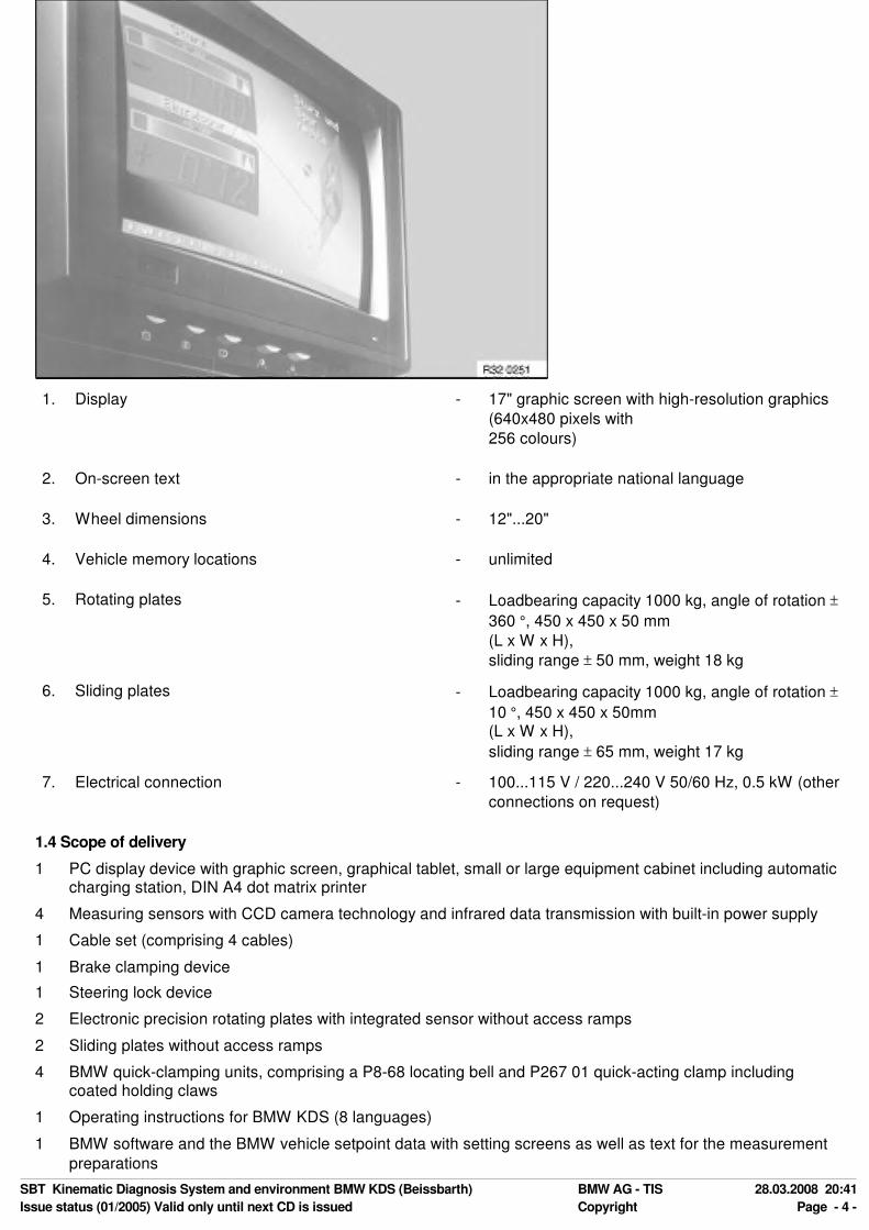
1. Display - 17" graphic screen with high-resolution graphics
(640x480 pixels with
256 colours)
2. On-screen text - in the appropriate national language
3. Wheel dimensions - 12"...20"
4. Vehicle memory locations - unlimited
5. Rotating plates - Loadbearing capacity 1000 kg, angle of rotation ±
360 °, 450 x 450 x 50 mm
(L x W x H),
sliding range ± 50 mm, weight 18 kg
6. Sliding plates - Loadbearing capacity 1000 kg, angle of rotation ±
10 °, 450 x 450 x 50mm (L x W x H),
sliding range ± 65 mm, weight 17 kg
7. Electrical connection - 100...115 V / 220...240 V 50/60 Hz, 0.5 kW (other
connections on request)
1.4 Scope of delivery
1 PC display device with graphic screen, graphical tablet, small or large equipment cabinet including automaticcharging station, DIN A4 dot matrix printer
4 Measuring sensors with CCD camera technology and infrared data transmission with built-in power supply
1 Cable set (comprising 4 cables)
1 Brake clamping device
1 Steering lock device
2 Electronic precision rotating plates with integrated sensor without access ramps
2 Sliding plates without access ramps
4 BMW quick-clamping units, comprising a P8-68 locating bell and P267 01 quick-acting clamp includingcoated holding claws
1 Operating instructions for BMW KDS (8 languages)
1 BMW software and the BMW vehicle setpoint data with setting screens as well as text for the measurement
preparations
SBT Kinematic Diagnosis System and environment BMW KDS (Beissbarth) BMW AG - TIS 28.03.2008 20:41
Issue status (01/2005) Valid only until next CD is issued Copyright Page - 4 -

1.5 Accessories required
2 Locating rods for positioning the vehicle
1 Set of sand bags for the prescribed loading
1.6 Accessories recommended
4 Quick-clamping units
2 Sets of access ramps
1 Remote control / display
1 Trolley (for ballast bags, rotating and sliding plates and 4 quick-acting clamps)
2. Measuring options using the BMW Kinematic Diagnosis System
2.1 Front axle
- Toe-in (single and total toe-in in relation to the geometrical drive axis)
- Camber (with steering wheel pointing straight ahead)
- Wheel displacement (in relation to the left-hand front wheel)
- Castor, kingpin inclination and toe-differential angle
2.2 Rear axle
- Toe-in (single and total toe-in in relation to the longitudinal centre plane of the vehicle --> previously called
symmetrical axis)
- Geometrical drive axis
- Camber
2.3 Other measuring options
- Rear wheel displacement
- Wheelbase difference
- Lateral displacement on right
- Lateral displacement on left
- Track difference
- Axial displacement
3. System description
3.1 BMW Kinematic Diagnosis System 1, based on the Beissbarth ML4000
The KDS 1 is available in two different designs at no extra charge:
SBT Kinematic Diagnosis System and environment BMW KDS (Beissbarth) BMW AG - TIS 28.03.2008 20:41
Issue status (01/2005) Valid only until next CD is issued Copyright Page - 5 -

1. Mobile workstation
2. Mobile compact cabinet
The larger workstation offers a small storage area for accessories, whilst the compact cabinet is mobile and ideal for restricted working areas. Both variants can be supplied as a cableless measuring system
(infrared). From the point of view of measuring technology, there is only a difference in the handling and equipping
of the system. For both designs, the four measuring sensors are stored in integrated inserts with rechargeablebattery charging points. When automatically charged over night, the measuring sensor batteries provide enough
power for
10 hours of continuous use.
3.2 Computer
- The KDS 1 system comprises tested and
reliable industrial components. The computer
is an IBM-compatible, 32-bit Intel processorwith CD ROM drive to the industry standard.
3.3 Graphical tablet
SBT Kinematic Diagnosis System and environment BMW KDS (Beissbarth) BMW AG - TIS 28.03.2008 20:41
Issue status (01/2005) Valid only until next CD is issued Copyright Page - 6 -

- All functions are shown in graphical form on a
"pictogram" panel. The panel is protected by aplexiglass cover. It can easily be replaced if
more extensive design modifications are
necessary. The operator interface has nomembrane and is thus protected against
damage. The main functions are activated by
clicking the icon with the digital pen.
3.4 Equipment cabinet
- The PC with graphic monitor and removableoperating panel, supports for the measuring
sensors, the remote control and the A4 printer
are integrated into the workstation. Thecharging station is located in the cabinet and
can also be connected to the measuring
sensors and the remote control using the plug-in cables (operating while simultaneously
charging the batteries).
3.5 Remote display
A cableless remote display can be supplied on
request. The remote control keys are only active
during measuring and adjustment (not for customerdata input, or if selecting a vehicle or editing the
setpoint data etc.). The following displays are
supported by the remote control:
- Measured value with setpoint / actualcomparison and tolerance bar
- Steering graphics for steering routines
- Live overview of the track / camber values with
a setpoint / actual comparison
- Rim run-out compensation
3.6 Measuring sensors with CCD camera
SBT Kinematic Diagnosis System and environment BMW KDS (Beissbarth) BMW AG - TIS 28.03.2008 20:41
Issue status (01/2005) Valid only until next CD is issued Copyright Page - 7 -

The measuring sensors are each equipped for
automatic measurement with two CCD camerasand their own processor for the cableless infrared
transmission of data with integrated batteries.
Benefits:
- No temperature deviation
- Very high measuring resolution (the track
could theoretically be measured in angular
seconds)
- Single track range of more than ± 9 degrees
for the constant display of toe-in when
changing the tie-rod ends
- Exact system accuracy, i.e. when carrying outmeasurements at the vehicle following rim
run-out compensation, the toe-in and camber
measurements are accurate to 2 angularminutes
3.7 BMW Quick-acting clamp
- BMW quick-acting clamp for holding the
measuring sensors precisely in position andmeasuring without rim run-out compensation.
- Note: Any existing quick-acting clamps, e.g.
from older F1600s or ML-3000s, must not beused on the BMW KDS.
3.8 Rotating / sliding plates
- Electronic precision rotating plates for the frontwheels with integrated sensor (360 degree
measuring range)
- Stable sliding plates for the rear wheels with aswivelling / rotating top plate
- Accessories: Cover hood for aluminium
rotating plates
3.9 Sensor pins
SBT Kinematic Diagnosis System and environment BMW KDS (Beissbarth) BMW AG - TIS 28.03.2008 20:41
Issue status (01/2005) Valid only until next CD is issued Copyright Page - 8 -
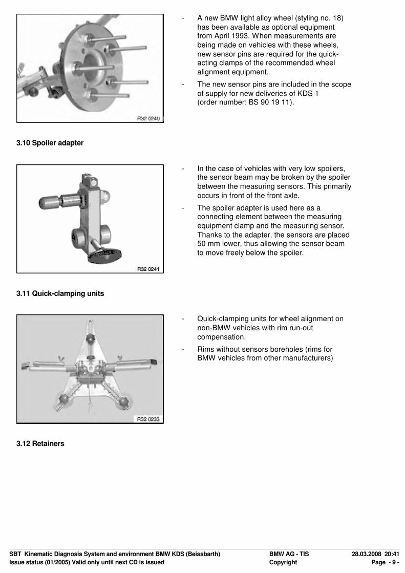
- A new BMW light alloy wheel (styling no. 18)
has been available as optional equipmentfrom April 1993. When measurements are
being made on vehicles with these wheels,
new sensor pins are required for the quick-acting clamps of the recommended wheel
alignment equipment.
- The new sensor pins are included in the scope
of supply for new deliveries of KDS 1 (order number: BS 90 19 11).
3.10 Spoiler adapter
- In the case of vehicles with very low spoilers,the sensor beam may be broken by the spoiler
between the measuring sensors. This primarily
occurs in front of the front axle.
- The spoiler adapter is used here as aconnecting element between the measuring
equipment clamp and the measuring sensor.
Thanks to the adapter, the sensors are placed50 mm lower, thus allowing the sensor beam
to move freely below the spoiler.
3.11 Quick-clamping units
- Quick-clamping units for wheel alignment on
non-BMW vehicles with rim run-out
compensation.
- Rims without sensors boreholes (rims forBMW vehicles from other manufacturers)
3.12 Retainers
SBT Kinematic Diagnosis System and environment BMW KDS (Beissbarth) BMW AG - TIS 28.03.2008 20:41
Issue status (01/2005) Valid only until next CD is issued Copyright Page - 9 -

- The most varied clamping options for the
measuring equipment are possible thanks tothe versatile retainers and the rubber-coated
thrust pieces, even on exotic light-alloy rims.
4. Workstation
4.1 Environment
Description: Requirements:
All lifting platforms currently recommended by BMW (see
Workshop Equipment Planning documentation, Issue
11) for wheel alignment meet the requirements for theBMW KDS.
- Wheel alignment pits
- Pillar-type lifts with set-down device
- 2 plunger-type lifting platforms with
set-down device
- Repair stands with set-down device
No particular requirements have to be met in respect ofthe location at which the BMW KDS is used. The
measuring device can be installed over working pits or
on lifting platforms.
- One measuring area
(approx. 4.5 m x 7.0 m).
- The rotating plates must be pinned to the platform
The support surfaces for the rotating and slidingplates may only display the following maximum
height difference:
- from left to right ± 0.5 mm
- from front to back ± 1.0 mm
- diagonally ± 1.0 mm.
Note:
A difference in the height of the rotary plates of ± 2 mm from left to right results in a measuring error of 4.8
° in the camber.
As a comparison: The camber tolerance on the E36 is ± 10'. The tyre tread difference or varying tyre
pressure cause measuring errors of the same magnitude.
4.2 Preconditions for alignment
When carrying out the wheel alignment, the front and rear wheels must be centred on the rotating and sliding
plates in order that all wheel suspensions remain free of tension during the steering routine and adjustment work.
As a result, the rotating and sliding plates for the relevant wheel bases and track widths of the vehicle to be
aligned must be moved.
SBT Kinematic Diagnosis System and environment BMW KDS (Beissbarth) BMW AG - TIS 28.03.2008 20:41
Issue status (01/2005) Valid only until next CD is issued Copyright Page - 10 -

4.3 Measuring tolerance
All measuring tolerances are system tolerances. This means that the sum of all individual tolerances gives thevalue shown in the example. Example of camber: Quick-acting clamp + measuring sensor + computer = 1' at a
measuring range of ± 3° (all BMW vehicles are within this measuring range).
4.4 Levelling the measuring station
The manufacturers of the BMW KDS (Beissbarth / Bosch) are able to measure the measuring area to the requiredaccuracy using levelling devices. Any "normal" water level is not suitable for this. Lifting platforms must be levelled
under load so that the uneven deflection in the travel rails is taken into account.
Important:
Adjustment work for the lifting platform concerned must be executed by a specialist (manufacturer's after-
sales service).
5. Chassis-related terms
5.1 Toe-differential angle
- The toe-differential angle (a) is the angular
position of the internal wheel on the curve in
relation to the external wheel on the curvewhen driving round bends. The steering is
designed such that the angular position of the
wheels in relation to each other changes as
the steering angle increases.
- In ideal cases, the wheel axes meet at point D
in any steering position (except for straight
ahead).
5.2 Camber
- The camber is the angle of inclination of the
wheel in relation to the vertical.
5.3 Toe-in
SBT Kinematic Diagnosis System and environment BMW KDS (Beissbarth) BMW AG - TIS 28.03.2008 20:41
Issue status (01/2005) Valid only until next CD is issued Copyright Page - 11 -

- The toe-in is the reduction in the distance
between the front of the wheels and the rear.The toe-in prevents the wheels from moving
apart whilst driving (wobbling and grinding).
5.4 Castor
- The castor is the kingpin angle seen from theside in the opposite direction of travel. The line
through the centre of the spring strut mount
and control arm ball joint corresponds to thekingpin.
5.5 Geometrical drive axis / symmetrical axis
- (1) The geometrical drive axis is the line
bisecting the angle of the overall rear wheel
toe. The measurements of the front wheelsrelate to this axis.
- (2) The symmetrical axis represents the centre
line through the front and rear axes.
5.6 Wheel displacement angle
SBT Kinematic Diagnosis System and environment BMW KDS (Beissbarth) BMW AG - TIS 28.03.2008 20:41
Issue status (01/2005) Valid only until next CD is issued Copyright Page - 12 -

- The wheel displacement angle is the angular
deviation of the connecting line of the wheelcontact points in relation to a line running at 90
° to the geometrical drive axis. The wheel
displacement angle is positive if the right-handwheel is displaced to the front, and is negative
if it is displaced to the rear.
5.7 Kingpin offset
- The kingpin offset is the distance from thecentre of the wheel contact point to the contact
point of the kingpin extrapolation.
6. Wheel suspension
Those parts which connect the wheel to the mostly load-bearing floor elements of the bodywork and guide it in therequired direction belong to the wheel suspension. They are connected by axles or other comparable structures
and guided by the arms. The wheel suspension plays a decisive role in the handling characteristics of a vehicle.
Two main groups have to be distinguished: 1. Rigid axle suspension and 2. Independent wheel suspension.
6.1 Rigid axle suspension
Description Advantages Disadvantages
The rigid axle suspension has a rigid
connection between both wheels orwheel pairs. Any change in one
wheel is more or less transferred to
the other. It is now only fitted as arear axle, if at all. However it is
frequently used for lorries or busses.
In the event of deflection taking
place, there are no changes to thecamber or wheel toe. This means:
less tyre wear and good track
stability.
Non-driven rear axles may also
acquire negative camber as well asincreasing tyre lateral guidance, thus
increasing tyre wear.
6.2 Independent wheel suspension
Description Advantages Disadvantages
SBT Kinematic Diagnosis System and environment BMW KDS (Beissbarth) BMW AG - TIS 28.03.2008 20:41
Issue status (01/2005) Valid only until next CD is issued Copyright Page - 13 -

State-of-the-art individual wheel
suspension is available on BMW
vehicles on the front and rear axles.This develop-
ment has its cause in mass inertia, as
a reduction in the non-suspendedmass improves wheel and ground
contact, and the wheel stays better
on the road. Control arms and trailingarms, which have to absorb high
longi-
tudinal and lateral forces to someextent, are required for guiding
independently suspended wheels.
Wheels suspended independently
from each other have no mutual
influence on each other.
Depending on the type, changes may
occur in the camber, wheel toe, track
width, castor and wheelbase.
7. Wheel alignment / procedure
7.1 Measuring options
An overview of all measuring options and values (VA = front axle, HA = rear axle) is shown below.
Measuring options Measuring accuracy In measuring range Total measuring range
Total wheel toe (VA + HA) ± 2' ± 2° ± 18°
Single wheel toe (VA + HA) ± 2' ± 2° ± 9°
Camber (VA + HA) ± 1' ± 3° ± 10°
Wheel displacement (VA) ± 2' ± 2° ± 9°
Geometrical drive axis ± 2' ± 2° ± 9°
Castor ± 4' ± 18° ± 22°
Kingpin inclination ± 4' ± 18° ± 22°
Toe-differential angle ± 4' ± 20° ± 20°
Maximum steering angle (VA ) ± 4' ± 60° ± 300°
Maximum steering angle (HA ) ± 4' ± 9° ± 9°
Castor correction range ± 4' ± 7° ± 10°
Note:
The measuring accuracy details only apply when using the precision rotating and sliding plates as well as
the BMW quick-acting clamps.
7.2 Preparatory work
Before commencing the measurement, preparatory work must be carried out at the measuring area and on thevehicle (see BMW KDS operating instructions). Preparatory work includes:
- Easy-running rotating and sliding plates
- Aligning the rotating and sliding plates in relation to the track width and wheelbase
- Centering the vehicle on the plates
- Applying the parking brake
- Removing the lock pins on the plates to prevent tension in the chassis under loading
- Checking the rim and tyre size, tread depth, tyre pressure, steering wheel play, wheel bearings and condition
of suspension and shock absorbers
- Fastening the measuring equipment to the wheels
- Loading the vehicle according to BMW KDS specifications
- Rock the vehicle firmly with the brakes released to ensure a stable centre position
- Lock the service brake using the brake clamping device
SBT Kinematic Diagnosis System and environment BMW KDS (Beissbarth) BMW AG - TIS 28.03.2008 20:41
Issue status (01/2005) Valid only until next CD is issued Copyright Page - 14 -

7.3 Initial / final measurement
This measurement can be carried out as a program-guided measurement in the same way as any subsequentadjusting work and the final measurement. The sequence of the chassis measuring points to be called up is
specified and controlled by the system software. The individual steps comprise:
- Driving straight ahead to correctly record the wheel toe and camber values for the rear axle
- Steering routine for recording the castor, kingpin inclination and toe-differential angle
- Recording the wheel toe and camber of the front axle (adjust the steering centre point in advance)
- Steering routine for measuring the maximum steering angle on the left/right
- Checking the overview of measured values with the setpoint and actual comparison of all measured values
7.4 Printing out the data
The report printout from the integrated DIN A4 printer is subdivided into three sections:
- Header lines with customer and vehicle identification data --> the customer data entered before beginning
the measurement as well as vehicle data are printed out here.
- Centre section with vehicle data --> this includes the make, type, model and vehicle model year defined when
the setpoint data record was selected. The values previously measured for height level, tyre pressure andtread depth are also printed in this section.
- The end section with all vehicle alignment values comprises the 3 columns initial measurement, setpoint
values and output measurement. The measured values are recorded separately in these three columns.
8. Special features
8.1 Free wheel alignment
With free wheel alignment the selection and sequence of the measuring points is freely selectable. The following
points must be observed for attaining the correct measurement results:
- Carry out all work in the same way as with the program-guided measurement.
- Before measuring the wheel toe and camber values for the rear axle, the steering must be in the "straightahead" position to ensure that it is perfectly aligned in relation to the longitudinal centre plane of the vehicle.
- Before measuring the single wheel toe values on the front axle, the centre of steering must be established to
ensure the correct position of the steering wheel.
8.2 System settings
The following settings must only be entered or set once: language, display format, date/time, advertising text,
remote control with display, rotating plate selection and printer settings. They remain stored.
9. BMW Kinematic Diagnosis System comparison (Bosch - Beissbarth)
SBT Kinematic Diagnosis System and environment BMW KDS (Beissbarth) BMW AG - TIS 28.03.2008 20:41
Issue status (01/2005) Valid only until next CD is issued Copyright Page - 15 -

Bosch Beissbarth
Measured value recording Infrared CCD camera
Data transmission Cable Infrared / cable
Measuring sensor power supply Cable Battery / cable
Remote control Infrared Infrared
Remote control with measured value
display
Cable Infrared
Setpoint data memory Floppy disk Hard disk
Measured value memory Always the last vehicle measured Unlimited vehicle memory
Operating system --- MS-DOS
Languages English and one language on request EN, DE, NI, SV, IT, FR, SP (further
languages can be called up)
Update 3.5" floppy disk 3.5" floppy disk using TIS/DIS
Monitor 20" 17"
Computer --- Pentium
Disk drives 2 x floppy disk 1 x floppy, 1 x CD ROM
10. Control modification (menu)
10.1 Remote control with display
The following steps show how the remote control with display is activated:
1. Call up the "Service" menu in special functions ("S" key)
2. Call up the "Remote control" sub-menu in the "Service" menu.
3. Select the "Remote control with display" item in the "Remote control" sub-menu - this configuration is
retained.
Important:
In the case of equipment without remote control, this must be configured to "No remote control".
10.2 Brief operating instructions
1. Activate the remote control with the "ON" button (it may also be switched on during alignment). The title page
will appear on the LCD.
2. Select "Straight ahead" of the "Initial measurement", "Adjustment work" or "Final measurement" at the
measuring equipment cabinet. The steering graphics for "Straight ahead" will appear on the LCD.
3. Use the "Forward arrow" to change to the next measurement image. Display blocks will appear on the LCD
with the designation of the measured value and tolerance bar with the measured value. If the measured
value is within the tolerance range, it is shown in dark figures against a light background. If the measuredvalue is outside the tolerance range, it will be shown in inverse video (light figures against a dark
background).
4. By pressing the "F" key shortly, you can move alternately between the designation of the measured value and
the setpoint value with the tolerance inside the display blocks.
5. You can scroll through the measured values using the "Forward arrow", "Backward arrow" and "Cancel" (red
dot) keys. The function of these keys is identical to that of the keys on the graphics panel.
6. Even with "Free alignment", it is possible to scroll through the measured values in the same way as with "
Program-guided alignment".
7. During measurement, the report print-out can be initiated using the "Printer" key. The remote control keys are
only active during measurement and adjustment (not during customer data input, vehicle selection etc.).
10.3 Display support
- Measured values with a setpoint/actual comparison and tolerance bar (setpoint figures can be displayed withthe "F" key)
SBT Kinematic Diagnosis System and environment BMW KDS (Beissbarth) BMW AG - TIS 28.03.2008 20:41
Issue status (01/2005) Valid only until next CD is issued Copyright Page - 16 -

- Steering graphics for steering routines
- Overview of measured values with current setpoint/actual comparison
- Rim run-out compensation
- With all other functions (e.g. customer input), the title illustration appears on the LCD display
Note:
If the data transmission from the remote control to the computer is interrupted, the remote control icon in
the bottom right-hand corner of the screen changes colour from green to red and the illustration on the
LCD display is shown inversely - black turns to white, white to black. This change does not take place inthe title illustration. Once the line-of-sight connection has been re-established, the remote control
continues to operate from the point of interruption in the program. A continuous visual connection during
alignment is therefore not necessary.
- The "Hour glass" icon in the LCD display means: "Please wait".
- The "Battery" icon in the top right-hand corner of the LCD display means that the battery reserve has
been reached.
- To switch off the remote control: press the "F" key for 5 seconds, then return it to its charging unit orconnect it to a charge cable. The title illustration will again appear as a charging check.
- If, during the measurement, the remote control has been placed back in the charging unit, it must be
switched on again using the "ON" button.
11. Updating the software / setpoint data
Floppy disks will no longer be sent to BMW partners who have acquired a "BMW KDS
(Beissbarth / Bosch)". For cost-related reasons, you can create these disks yourself on the "DIS-tester" or on the "TIS/EPC server". The data for this is regularly updated on the TIS CD.
11.1 Requirements
- BMW KDS (Beissbarth / Bosch)
- TIS CD program status (Beissbarth): from CD 12/95
- EPC program status: from 12/95
- TIS CD program status (Bosch): from CD 08/97
- DIS program status: from V6.0
- 3.5" diskettes, 1.44 MB (Beissbarth 5 diskettes / Bosch 1 diskette)
11.2 Procedure (Beissbarth)
1. Go to the "Administration" screen
2. Select the KDS button
3. Select Beissbarth
4. Insert "Diskette 1" on request and confirm with "OK" (program diskette 1 of 2 is created,
label it)
5. Insert "Diskette 2" on request and confirm with "OK" (program diskette 2 of 2 is created,
label it)
6. Insert "Diskette 3" on request and confirm with "OK" (setpoint data diskette 1 of 3 is created, label it)
7. Insert "Diskette 4" on request and confirm with "OK" (setpoint data diskette 2 of 3 is created, label it)
8. Insert "Diskette 5" on request and confirm with "OK" (setpoint data diskette 3 of 3 is created, label it)
9. Perform update and/or setpoint data on the KDS in the usual manner with the diskettes which have just been
created.
11.3 Procedure (Bosch)
1. Go to the "Administration" screen
2. Select the KDS button
3. Select Bosch
4. Label "Diskette 3.1", insert it into the drive on request and confirm with "OK" (2x) --> Setpoint data is copied
SBT Kinematic Diagnosis System and environment BMW KDS (Beissbarth) BMW AG - TIS 28.03.2008 20:41
Issue status (01/2005) Valid only until next CD is issued Copyright Page - 17 -

to the diskettes.
5. Insert setpoint data diskette 3.1 into the 3.1 floppy disk drive, insert operating system diskette 3.0 into the 3.0 drive.
6. Switch on the machine in the usual manner.
Important:
When creating the KDS diskettes, all data on the diskettes used is overwritten.
Note:
In the event of an error, a corresponding message is shown and the program is cancelled completely.
The procedure must be run from the beginning again and all data on the diskette will be deleted. A new diskette may have to be used.
12. Creating, copying and editing setpoint data
12.1 Copying
- Press the "C" button and select the vehicle to be copied.
- Select the "Edit setpoint data" menu item from the special functions. Create a new vehicle in the usual
manner. The setpoint values for the last vehicle selected will appear in the data input screen. Enter the dataand save the data record.
12.2 Creating
- Press the "C" button and select the "Edit setpoint data" menu item from the special functions. Create a new
vehicle in the usual manner. An empty data input screen will appear. Enter the data and save the datarecord.
12.3 Editing
- Factory-programmed setpoint data can neither be deleted nor modified. If this data does need to be modified,
a new vehicle with modified setpoint data must be created. New vehicles created by the user are identified bya "+" in the selection menu. These vehicles can be deleted by the user using the "-" key or modified using the
"< >" key. These keys only appear if vehicles have been entered by the user.
13. Special functions
13.1 Customer-specific printer report header
The sub-item "Customer-specific text" must be called up in the "Special functions" menu. An input screen willappear on the monitor. This input screen must be filled out with the name and address and stored with the "S"
screen key. The text entered is inserted into the report header.
13.2 Adjusting options
- Call up the "Service" menu in the special functions ("S" key).
- Select the "Wheel toe adjustment" item or the "Camber adjustment" item from the "Adjustment" sub-menu.
The toe and camber adjustment program will guide the user step by step through the adjustment using text
and images. The measuring deviation for each measuring sensor will be shown on the screen when theadjustment has been completed.
- You can store the adjustment values in the measuring sensor using the "Store" key or you can quit the
program with the "Red dot key" without saving them (check). The adjustment values can be printed out.
13.3 Rotating plate test
- Call up the "Service" menu in the special functions ("S" key).
- Call up the "Rotating plate" item in the "Service" menu. Turn the left-hand and
right-hand rotating plate and check the display on the screen. Important: The measuring range is ± 306
degrees.
13.4 Viewing and deleting customer entries from database
- Call up the menu item "Delete" in the "Database" menu in the special functions. The data input screen will
appear. Fill in the search fields with the data to be deleted.
- Use the "-" button to delete this data record. A new data record can then be highlighted and deleted with thedigital pen.
SBT Kinematic Diagnosis System and environment BMW KDS (Beissbarth) BMW AG - TIS 28.03.2008 20:41
Issue status (01/2005) Valid only until next CD is issued Copyright Page - 18 -

- You can scroll through the entire database with the "Arrow up" and "Arrow down" keys.
- You can quit the delete function by pressing the cancel key (red dot).
14. Modifications within program
Further modifications were carried out within the program which only slightly change the program sequence butwhich optimise the alignment in respect of comfort and speed. This is described below:
- Optimisation of the rim run-out compensation in respect of speed.
- Optimisation of the steering routines: Highlighted values within the gate can still be corrected. The message "
Rotating plates not connected" no longer causes the steering routine to be cancelled. Furthermeasurements can be carried out after the rotating plates have been connected.
- Standardisation of screen colours with the colours on the tablet.
- Addition of texts in several foreign languages.
- Elimination of program-related and cosmetic faults.
- Electronic water level.
- Omission of kingpin inclination measurement.
15. Faults
15.1 Tyre faults
Fault Effect
1 Wheel toe, camber, toe-differential angle and castor
not correct
1 Severe tyre squeaking even at relatively low
speeds
2 Excessive toe-in and excessive positive camber 2 Tyres are worn down on one outside edge in the
longitudinal direction
3 Excessive negative camber 3 Tyre wear on inside edge
4 Worn front-axle suspension on front-wheel-drive
vehicles
4 Increased noise /
Vehicle pulls on one side when accelerating
5 Incorrect wheel alignment 5 Wheels scrubbing /
Tyre surface shows feathering in the tread
6 Play in the suspension due to mechanical parts
(suspension, steering)
6 Washout /
Wobbling of front wheels
7 Tyre pressure too low 7 Outside tyre surface wear
15.2 Front axle faults
Fault Cause Remedy
1. Toe deviation a) Vehicle not in normal position a) Correct height level
b) Tie rod(s) bent b) Replace tie rod(s)
c) Tie rod ball joints worn c) Replace tie rod(s)
d) Rubber mount in control arm
defective
d) Replace control arm
SBT Kinematic Diagnosis System and environment BMW KDS (Beissbarth) BMW AG - TIS 28.03.2008 20:41
Issue status (01/2005) Valid only until next CD is issued Copyright Page - 19 -

2. Camber deviation: The camber
is fixed during the design stageand cannot be adjusted.
a) Rubber mount in control arm
defective
a) Replace control arm
b) Control arm deformed b) Replace control arm
c) Spring strut deformed c) Replace spring strut
d) Traction strut worn d) Replace control arm
e) Spring deflection too great e) Replace coil spring, height level
f) Front axle carrier deformed f) Replace front axle carrier
g) Spring strut mount deformed g) Repair forward structure
h) Distortion in the floor assembly(engine bracket)
h) Repair body
3. Castor deviation: The castor isfixed during the design stage
and cannot be adjusted.
a) Rubber mount for tension /traction strut defective
a) Replace rubber mount
b) Tension / traction strut deformed b) Replace tension / traction strut
c) Control arm deformed c) Replace control arm
d) Spring strut deformed d) Replace spring strut
e) Wheelhouse deformed (springstrut mount)
e) Repair forward structure
f) Distortion in the floor assembly
(engine bracket)
f) Repair body
4. Toe-differential angle deviation Requirement: camber and castor arecorrect
a) Tie rods unevenly adjusted a) Set wheel toe on left and right
to identical values
5. Wheel displacement deviation Requirement: Front wheels have
same single toe in relation to the
geometrical axis
a) Front axle carrier deformed a) Replace front axle carrier
b) Engine bracket deformed b) Repair body
c) Control arm deformed c) Replace control arm
d) Tension / traction strut deformed d) Replace tension / traction strut
15.3 Rear axle faults
Fault Cause Remedy
1. Camber deviation a) Vehicle not in normal position:spring deflection too great
a) Correct height level
SBT Kinematic Diagnosis System and environment BMW KDS (Beissbarth) BMW AG - TIS 28.03.2008 20:41
Issue status (01/2005) Valid only until next CD is issued Copyright Page - 20 -

b) Rubber mount on rear axle
carrier defective
b) Replace rubber mount
c) Rear axle carrier deformed c) Check rear axle carrier and
replace, if necessary
d) Control arm deformed d) Check control arm and replace,
if necessary
e) Traction strut deformed e) Check traction strut andreplace, if necessary
f) Distortion in the floor assembly f) Repair body
g) Swinging arm deformed g) Replace swinging arm
2. Rear wheel position is not
correct
a) Rear axle carrier has been
shifted laterally
a) Check the rubber mounts on
the rear axle carrier andreplace, if necessary
b) Distortion in the floor assembly b) Repair body
3. Toe deviation a) Vehicle not in normal position,i.e. spring deflection too great
a) Correct height level
b) Rubber mount in rear axle carrier
defective
b) Replace rubber mount
c) Control arm deformed c) Replace control arm
d) Rubber mount and swinging arm
defective
d) Replace swinging arm
e) Rear axle carrier deformed e) Check rear axle carrier and
replace, if necessary
f) Traction strut deformed f) Check traction strut and
replace, if necessary
4. Deviation from the geometrical
drive axis
Requirement: Total wheel toe is
correct
a) Distortion in the floor assembly a) Repair body
Further details on the "Kinematic Diagnosis System" can be found in the operating instructions for the BMW
KDS (Beissbarth / Bosch).
Functional and system descriptions are not subject to change. Parts availability and immediate orderingavailability cannot be derived from this information. The specialist departments will be providing further details
at the relevant time.
SBT Kinematic Diagnosis System and environment BMW KDS (Beissbarth) BMW AG - TIS 28.03.2008 20:41
Issue status (01/2005) Valid only until next CD is issued Copyright Page - 21 -


![LAUNCH X-431 BMW Diagnosis · LAUNCH X-431 BMW Diagnosis 3 Entering Function Menu home After connection, press [POWER] key to start X-431.](https://static.fdocuments.us/doc/165x107/5bb648c109d3f237458b93a5/launch-x-431-bmw-diagnosis-launch-x-431-bmw-diagnosis-3-entering-function-menu.jpg)