KinectAvatar: Fully Automatic Body Capture Using a Single Kinectwychang1/papers/accv2012final... ·...
14
KinectAvatar: Fully Automatic Body Capture Using a Single Kinect Yan Cui † , Will Chang ‡ , Tobias N¨ oll † , Didier Stricker † † Augmented Vision, DFKI Abstract. We present a novel scanning system for capturing a full 3D human body model using just a single depth camera and no auxiliary equipment. We claim that data captured from a single Kinect is sufficient to produce a good qual- ity full 3D human model. In this setting, the challenges we face are the sensor’s low resolution with random noise and the subject’s non-rigid movement when capturing the data. To overcome these challenges, we develop an improved super- resolution algorithm that takes color constraints into account. We then align the super-resolved scans using a combination of automatic rigid and non-rigid reg- istration. As the system is of low price and obtains impressive results in several minutes, full 3D human body scanning technology can now become more acces- sible to everyday users at home. 1 Introduction Three-dimensional geometric models of real world objects, especially human models, are essential for many applications such as design, virtual prototyping, quality assur- ance, games, and special effects. However, highly trained artists are mainly responsible for performing this modeling task, often using specialized modeling software. While 3D scanning technology has been available as an alternative for some time, it is still not used very widely for capturing models. This is because scanning devices are still ex- pensive and often require expert knowledge for operation. And many scanning systems are limited for only rigid objects. In this work, we present a novel approach to full 3D human body scanning which employs a single Microsoft Kinect [1] sensor. The Kinect has a variety of advantages over existing 3D scanning devices. It can capture depth and image data at video rates without a significant dependence on specific lighting and texture conditions. Also the Kinect is compact, low-price, and as easy to use as a normal video camera. The challenge in using a single Kinect for scanning is that it provides relatively low-resolution data (320 × 240) with a high noise level. With these data characteristics, it is difficult to produce high-quality 3D models. Devices such as the Kinect were de- signed for use in object detection and natural user interfaces, not for high-quality 3D scanning. In addition, since we observe our subject only from a single, fixed location, movement of the subject is unavoidable during scanning. Therefore, we must estimate and compensate for this motion in order to combine scans from different viewpoints and produce a complete model. ‡ Author has no affiliation at this time. Contact address: [email protected]
Transcript of KinectAvatar: Fully Automatic Body Capture Using a Single Kinectwychang1/papers/accv2012final... ·...
KinectAvatar: Fully Automatic Body Capture Using aSingle Kinect
Yan Cui†, Will Chang‡, Tobias Noll†, Didier Stricker†
†Augmented Vision, DFKI
Abstract. We present a novel scanning system for capturing a full 3D humanbody model using just a single depth camera and no auxiliary equipment. Weclaim that data captured from a single Kinect is sufficient to produce a good qual-ity full 3D human model. In this setting, the challenges we face are the sensor’slow resolution with random noise and the subject’s non-rigid movement whencapturing the data. To overcome these challenges, we develop an improved super-resolution algorithm that takes color constraints into account. We then align thesuper-resolved scans using a combination of automatic rigid and non-rigid reg-istration. As the system is of low price and obtains impressive results in severalminutes, full 3D human body scanning technology can now become more acces-sible to everyday users at home.
1 Introduction
Three-dimensional geometric models of real world objects, especially human models,are essential for many applications such as design, virtual prototyping, quality assur-ance, games, and special effects. However, highly trained artists are mainly responsiblefor performing this modeling task, often using specialized modeling software. While3D scanning technology has been available as an alternative for some time, it is still notused very widely for capturing models. This is because scanning devices are still ex-pensive and often require expert knowledge for operation. And many scanning systemsare limited for only rigid objects.
In this work, we present a novel approach to full 3D human body scanning whichemploys a single Microsoft Kinect [1] sensor. The Kinect has a variety of advantagesover existing 3D scanning devices. It can capture depth and image data at video rateswithout a significant dependence on specific lighting and texture conditions. Also theKinect is compact, low-price, and as easy to use as a normal video camera.
The challenge in using a single Kinect for scanning is that it provides relativelylow-resolution data (320× 240) with a high noise level. With these data characteristics,it is difficult to produce high-quality 3D models. Devices such as the Kinect were de-signed for use in object detection and natural user interfaces, not for high-quality 3Dscanning. In addition, since we observe our subject only from a single, fixed location,movement of the subject is unavoidable during scanning. Therefore, we must estimateand compensate for this motion in order to combine scans from different viewpointsand produce a complete model.
‡Author has no affiliation at this time. Contact address: [email protected]
2 Yan Cui, Will Chang, Tobias Noll, Didier Stricker
We claim that data captured from a single Kinect is sufficient to produce a goodquality full 3D human model, without any additional equipment or shape priors (e.g. aturntable, additional Kinects, or a database of human body models). A key benefit of ouralgorithm is that it only relies on the input data and does not require an explicit shapemodel of the scanned subject. This allows us to reproduce personalized detail geometrysuch as faces and clothing. Our pipeline leverages prior work in depth super-resolutionand articulated non-rigid registration. The contributions are
– a pipeline for automatically scanning full human body using a single Kinect,– an improved depth super-resolution algorithm, taking color constraints into ac-
count,– and a unified formulation of rigid and non-rigid registration under a probabilistic
model, improving upon prior work [2] [3] for registration quality in high noisescenarios and for solving the loop closure problem.
In the following section, we discuss the relationship of this paper to previous work.Afterwards, we give technical details of our scanning system and verify our main claimby demonstrating results on several real-world datasets.
2 Related Work
Recent developments in low cost real-time depth cameras have opened up a new field for3D content acquisition. In particular, several publications about 3D shape scanning withthe Kinect have appeared. Henry et al. [4] build dense 3D maps of indoor environments,and Newcombe et al. [5] present a real-time 3D scanning system for arbitrary indoorscenes. These projects focus mainly on scanning static scenes of indoor environments.
Specifically concerning the problem of human body scanning, Cui et al. [6] try toscan a human body with one Kinect. However, they do not use the color information,and fundamental proplem is that they can not handle non-rigid movement, so the recon-structed results in the arm and leg parts are not of high quality. The work by Weiss et al.[7] estimates the body shape by fitting the parameters of a SCAPE model [8] to depthdata and image silhouettes from a single Kinect. In contrast, our work does not requirea prior shape model and relies mainly on registration. Thus, our method reproducespersonalized details such as faces or dresses from the scans. Most recently, Tong et al.[9] present a system to scan a body using three Kinects and a turntable. They also uti-lize a global non-rigid registration algorithm which uses a rough template constructedfrom the first depth frame. While we share some similarities, our system setup is muchsimpler (using only a single Kinect), and our global registration works directly with thedata without requiring a rough template.
As the raw Kinect depth data is of low resolution with high noise levels, a smoothingalgorithm should be applied as a pre-processing step. Newcombe et al. [5] apply abilateral filter [10] to the raw Kinect depth map to obtain a discontinuity preserveddepth map with reduced noise. Schuon et al. [11] develop a super-resolution algorithm(LidarBoost) to improve the depth resolution and data quality of a ToF range scan, andCui et al. [2] further develop this method. In this paper, we compare these existing

KinectAvatar: Fully Automatic Body Capture Using a Single Kinect 3
(a) Working setup
Super-resolution
Global RigidRegistration
Non-RigidRegistration
(b) Processing pipeline
Fig. 1. Outline of our working setup and processing pipeline.
methods and provide a new super-resolution algorithm for the Kinect depth and colordata. This improves the resolution, reduces the noise, and preserves shape detail.
The global rigid registration problem is an important topic in object scanning. It-erative Closest Points (ICP) and its variants [12] can solve the local rigid alignmentproblem. Global rigid alignment techniques [13][14][15] can be used to register thescans against each other and solve the well-known loop closure problem. However, theinput data used in these algorithms are acquired using structured light or laser scan-ning, which has high resolution and little noise. Cui et al. [2] present a probabilisticscan alignment approach that explicitly takes the sensor’s noise characteristics into ac-count. However, this method can only solve a local alignment task. We improve upontheir approach and develop a probabilistic global alignment algorithm.
Even after the global rigid alignment, the scans do not align well because of thehuman bodies’ non-rigid deformation during scanning (especially in the arms and legs).Aligning these scans is a challenging task that often requires high quality scan dataand small changes of the pose in each scan [3][16][17][18][19][20][21]. While most ofthese approaches mainly deal with high-resolution scan data, we propose a robust non-rigid global alignment that can work well even with the Kinect’s resolution and noiselevels. Since the human body is largely articulated, we build on the global articulatedregistration work by Chang and Zwicker [3] and significantly improve the algorithmusing a probabilistic scan alignment approach robust to the noise of the scans.
3 Overview
First, we give an overview of our scanning system, easily built as shown in Fig. 1a. Theuser stands before a Kinect in a range of about 2 meters, such that the full body falls inthe Kinect’s range of view. Then, the user simply turns around 360 degrees for about 20to 30 seconds while maintaining an approximate “T” pose.
While scanning, we capture s = 10 frames as one view “chunk” with depth mapsD` = (D1, . . . , Ds) and color maps C` = (C1, . . . , Cs). We then stop 0.5 seconds,capture another chunk, stop, capture, and so on until the human body has turned com-pletely. The capture process yields about 10 raw data frames for each view, with thebody turning approximately 30 degrees between the views. This ensures that there areenough overlapping areas for registration while providing full 360 degree coverage. Thedepth maps and color maps are calibrated and aligned (calibration off-line). In total, weget K chunks, where K = 30 ∼ 40. Since the Kinect captures at about 30 FPS, thedisplacement is relatively small within a single chunk.
4 Yan Cui, Will Chang, Tobias Noll, Didier Stricker
The resulting range data is then processed by our reconstruction algorithm, com-prised of the following steps (Fig. 1b). First, a super-resolution step takes each chunk asinput, and produces a single super-resolved depth scan with both greater depth accuracyand resolution (Sec. 4). Second, global rigid and non-rigid alignment steps combine thesuper-resolved scans into a final model (Sec. 5). Here, by “global” we mean that all ofthe frames in the sequence are aligned together. After the alignment is complete, wereconstruct a single mesh using Poisson mesh reconstruction [22] as a post processingstep. Finally, textures are created with the Kinect’s raw color data (Sec. 6). Our resultsshow that this system can capture impressive 3D human shapes with personalized ge-ometric details. In subequent sections, we describe each step of the system in moredetail.
4 Super-resolution
We apply our super-resolution algorithm to each chunk of depth images, yielding Knew super-resolved depth maps H` with much higher X/Y resolution and less noise.Our algorithm is largely based on Cui et al [23].
First, we align all depth and color maps of a chunk to its middle frame using op-tical flow. This is sufficiently accurate since the maximum viewpoint displacementsthroughout the entire chunk are typically one to three pixels. This corresponds to aturning speed of aobut 30 seconds per revolution by the user. Second, we extract a high-resolution denoised depth mapH` from the aligned low resolution depth and color mapsby optimizing the following objective function:
minH`
Edata(D1, . . . , Ds, C1, . . . , Cs, H`) + γEreg(H`) , (1)
Edata =s∑
k=1
‖Wk ◦ (H` − f (Dk))‖2
Wk = 1
Ck− 1s
s∑k=1
Ck
.(2)
Here, we upsample the depth data by a factor β = 2 in both X and Y dimensions. Afterthe optimization, the depth map H` is converted into a 3D point cloud Y` = {yj | j =1 . . . β2NXNY } using the Kinect’s intrinsic parameters after optimization (NX , NYare the resolution of the raw depth data).
To explain the optimization further, Edata measures the agreement of H` with thelow resolution depth maps. Here, f is a function, which upsamples the low resolutionD` to higher resolution of β2NXNY and align to the center depth frame. We performedexperiments to determine the best resampling strategy. It turned out that a nearest neigh-bor sampling from the low resolution images is preferable over any type of interpolatedsampling. Interpolation implicitly introduces unwanted blurring that leads to a less ac-curate reconstruction of high-frequency shape details in the superresolved result. Wk
is a per-pixel weight that measures the quality of the optical flow alignment, ◦ denoteselement-wise multiplication, and ‖‖2 denotes sum of the square normal for each pixel.The 1
· notation for Wk means that we invert the value per pixel. Since the human ismoving in 3D space but optical flow just considers the movement in 2D image space,
KinectAvatar: Fully Automatic Body Capture Using a Single Kinect 5
(a) Raw data (b) Off color (c) Off color(AEE = 4.84)
(d) With color (e) With color(AEE = 2.98)
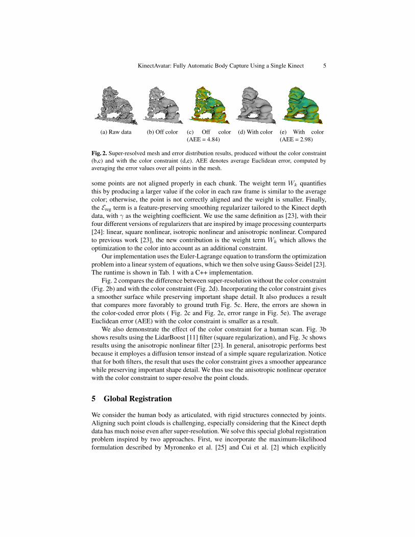
Fig. 2. Super-resolved mesh and error distribution results, produced without the color constraint(b,c) and with the color constraint (d,e). AEE denotes average Euclidean error, computed byaveraging the error values over all points in the mesh.
some points are not aligned properly in each chunk. The weight term Wk quantifiesthis by producing a larger value if the color in each raw frame is similar to the averagecolor; otherwise, the point is not correctly aligned and the weight is smaller. Finally,the Ereg term is a feature-preserving smoothing regularizer tailored to the Kinect depthdata, with γ as the weighting coefficient. We use the same definition as [23], with theirfour different versions of regularizers that are inspired by image processing counterparts[24]: linear, square nonlinear, isotropic nonlinear and anisotropic nonlinear. Comparedto previous work [23], the new contribution is the weight term Wk which allows theoptimization to the color into account as an additional constraint.
Our implementation uses the Euler-Lagrange equation to transform the optimizationproblem into a linear system of equations, which we then solve using Gauss-Seidel [23].The runtime is shown in Tab. 1 with a C++ implementation.
Fig. 2 compares the difference between super-resolution without the color constraint(Fig. 2b) and with the color constraint (Fig. 2d). Incorporating the color constraint givesa smoother surface while preserving important shape detail. It also produces a resultthat compares more favorably to ground truth Fig. 5c. Here, the errors are shown inthe color-coded error plots ( Fig. 2c and Fig. 2e, error range in Fig. 5e). The averageEuclidean error (AEE) with the color constraint is smaller as a result.
We also demonstrate the effect of the color constraint for a human scan. Fig. 3bshows results using the LidarBoost [11] filter (square regularization), and Fig. 3c showsresults using the anisotropic nonlinear filter [23]. In general, anisotropic performs bestbecause it employes a diffusion tensor instead of a simple square regularization. Noticethat for both filters, the result that uses the color constraint gives a smoother appearancewhile preserving important shape detail. We thus use the anisotropic nonlinear operatorwith the color constraint to super-resolve the point clouds.
5 Global Registration
We consider the human body as articulated, with rigid structures connected by joints.Aligning such point clouds is challenging, especially considering that the Kinect depthdata has much noise even after super-resolution. We solve this special global registrationproblem inspired by two approaches. First, we incorporate the maximum-likelihoodformulation described by Myronenko et al. [25] and Cui et al. [2] which explicitly

6 Yan Cui, Will Chang, Tobias Noll, Didier Stricker
(a) Raw data (b) LidarBoost off & with color (c) Anisotropic off & with color
Fig. 3. Super-resolved meshes using the LidarBoost and Anisotropic filters. The images compareresults with and without the color constraint.
takes into account the sensor’s noise characteristics. Second, we employ the articulatedmodel described in Chang and Zwicker [3] to describe the non-rigid motion. Here, thesurface motion is expressed in terms of an articulated model. We extend their ideas toour setting and develop an approach for global rigid and non-rigid registration for noisyKinect data.
5.1 Problem Setup
The input to registration are 3D point clouds Yf = {yf,n | n = 1, . . . , Nf} from eachsuper-resolved frame f ∈ H`. Here, Nf is number of points in frame f .
We need to solve for the motion of each frame so that all frames align to each other.To parameterize the motion, we define a set of rigid transformations M0
f ,M1f ,M
2f , . . .
for each frame f . This set will describe the motion of the frame from its original loca-tion. Since there are multiple transformations per frame, we will need to define whichtransformation associates with each point. We define this association as a label i(n): theindex of the transformation assigned to yf,n. Therefore, M i(n)
f will be the transforma-tion for the point yf,n. This parameterization of the motion is essentially an articulatedmodel, since the points divide into rigid parts according to their label [3].
When we set up the problem in this way, the alignment task then reduces to solv-ing for the transformations and labels that give the best alignment possible. We modela likelihood function describing the quality of the alignment, and we maximize thislikelihood for all frames simultaneously to produce the result.
Conformal Geometric Algebra. We use an exponential map based on conformal geo-metric algebra to express the transformations. The Euclidean transformations of a pointX into X ′ in the conformal space caused by a motor M and a reverse motor M isapproximated as:
X ′ =MXM = E + e∞(x− l · x−m), (3)
where E is the identity matrix, e∞ is the point at infinity, and l,m ∈ R3 correspondsto the rotation and traslation in the conformal geometric algebra, respectively. Thisformulation has the advantage that we only have 6 degrees of freedom (DoF). A for-mulation with a 3 × 3 ∈ R matrix and a 3 × 1 ∈ R translation vector would have
KinectAvatar: Fully Automatic Body Capture Using a Single Kinect 7
12 variables instead. A further advantage is that we can gain linear equations with re-spect to minimizing an energy function using the motor. For notational convenience,we use the expression T i(n)f (X) to denote the transformation of point X using M i(n)
f
(T i(n)f (X) = Mi(n)f XM
i(n)f ). For more background information for Eqn. 3 and its
optimization, please refer to the references [26][27][28].Deformation model. To aid the optimization, we find neighbor relations between therigid parts and constrain such neighbors to be joined together at a common location.These locations we call “joints” and infer them during the optimization. Specifically,we use ball joint relations (3 DoF) between rigid parts, expressed by a single pointdenoted yf,ab ∈ R3 relating two rigid transformationsMa
f andM bf . The joints constrain
neighboring transformations to agree on this common ball joint location. This ensuresthat the rigid parts stay connected and do not drift away. We estimate the joint locationsautomatically using the same technique as in previous work [3].Difference to Previous Work. Our problem setup is similar to that of Chang andZwicker [3]. However, there are notable differences in our work. First, we do not sub-sample the frames but instead define a label for all points in all frames. Therefore, weuse the mesh connectivity in each frame to define neighborhood relationships betweenthe points.
Second, we do not define a reference frame or employ a dynamic sample graph. Thetransformations operate directly on the scanned points so that every scan aligns to allothers. In addition, since we associate the labels directly to the scan points, we obtaina separate, independent segmentation per frame (based on the motion occuring in theframe). This means that, unlike prior work, all frames are moving independently. Also,we have a separate set of joint locations per frame, whereas the joint locations weredefined on the reference frame previously. Changing the problem setup in this mannerallows us to optimize the alignment of all frames in a single optimization step.Probabilistic model. The key ingredient for making the registration robust to noiseand outliers is the probabilistic modeling of the point clouds. We consider each Yf tobe generated from a Gaussian Mixture Model (GMM), with density as follows [2][25]:
p(x) =
Nf∑n=1
1
Nfp (x | n) with p (x | n) ∝ N(yf,n, σ
2I) . (4)
Simply speaking, p(x) gives the probability that x ∈ R3 is generated by Yf . As theequation shows, we model the GMM using the original point set Yf and center eachmulti-variate Gaussian N(yf,n, σ
2I) at the scanned points yf,n. All Gaussians sharethe same isotropic covariance matrix σ2I , with I as a 3 × 3 identity matrix and σ2 asthe variance in all directions.
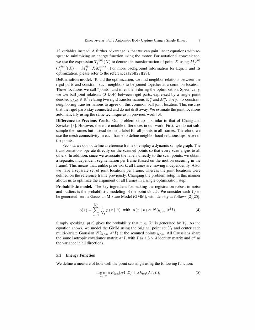
5.2 Energy Function
We define a measure of how well the point sets align using the following function:
argminM,L
Edata(M,L) + λEreg(M,L), (5)

8 Yan Cui, Will Chang, Tobias Noll, Didier Stricker
whereM is the entire transformation set and L are the labels for all the points of theK frames. Edata measures the alignment distance between points in each frame, Eregconstrains the labels for a smooth segmentation and also neighboring transformationsto agree on a common joint location. λ is weighting coefficient.Data Term Edata. To achieve a closed model, all frames should be aligned globallywith minimal distance. For each pair of frames f and g, the alignment task is performedby minimizing the negative log-likelihood based on the probabilistic model:
Edata(M,L) = −∑f,g
Nf∑n=1
logNg∑m=1
exp
(∥∥∥T i(n)f (yf,n)−T j(m)
g (yg,m)∥∥∥2
−2σ2f,g
), (6)
where i(n) is the index of the transformation assigned to the point yf,n, and j(m) thesame for the point yg,m but based on the segmentation of frame g. The variance σ2
f,g ofmixture components is estimated separately for each point using
σ2f,g =
1
NfNnear
Nf∑n=1
Nnear∑m∈Near(yf,n)
∥∥∥T i(n)f (yf,n)− T j(m)g (yg,m)
∥∥∥2, (7)
where m ∈ Near(yf,n) denotes the indices of the nearest Nnear points in frame g forpoint yf,n. In our experiments, we use a value of Nnear = 20.Regularization term Ereg. There are two parts for the regularization term Ereg [3].The first part is a smoothness term for the labels, which constrains neighboring pointsn,m to have a similar label to ensure a smooth segmentation result. If the label is notthe same (i(n) 6= i(m)), we apply a penalty I(·) = 1 which is added to Ereg.
The second part is the joint constraint which ensures that the rigid parts do not driftaway from each other. Each ball joint specifies that its point yf,ab should move to thesame location when applyingMa
f andM bf . With α providing a relative weighting of the
two constraints, the resulting energy function is
Ereg(M,L) =∑f
∑
(n,m)∈f
I (i(n) 6= i(m))
︸ ︷︷ ︸Label Constraint
+ α∑
Joints (a,b)
∥∥T af (yf,ab)− T bf (yf,ab)∥∥2
︸ ︷︷ ︸Joint Constraint
.
(8)
5.3 Expectation-Maximization
Therefore, for each of the K frames, we minimize the above energy to get a the setof transformations per frame. We use an iterative Expectation Maximization (EM) likeprocedure to find a maximum likelihood solution of Eqn. 5.
During the E-step, the best alignment parameters from the previous iteration areused to compute an estimate of the posterior P old
f,g(m | yf,n) of mixture componentsusing Bayes theorem [2]. This posterior is a matrix of dimension Ng ×Nf , where eachmatrix entry pmn gives a conditional probability for a pair of points (yf,n, yg,m) from

KinectAvatar: Fully Automatic Body Capture Using a Single Kinect 9
frame f and g. Computing this matrix is intensive and would spend about 10 hours fortwo frames. It turns out that most entries are zero, and a relatively small number of pairsare actually close enough to yield a non-zero probability. Therefore, we only considerthe Nnear closest points in frame g for each point in frame f . As mentioned earlier, weuseNnear = 20 which we empirically determined to be sufficient for our experiments. Inaddition, we compute the posterior matrix values only for four frames before and fourframes after Yf . These eight neighbor frames were enough for the registration, sincethe subject turns continuously in our experiments. Using these approximations, we cansimultaneously optimize the alignment of all frames in a reasonable computation time.
During the M-step, the new alignment parameter values are found by minimizingthe negative log-likelihood function, or more specifically, its upper bound Q whichevaluates to:
Q (M,L) =∑f,g
(Nf∑n=1
Ng∑m=1
P oldf,g (m | yf,n)
∥∥∥T i(n)f (yf,n)−T j(m)
g (yg,m)∥∥∥2
2σf,g2
). (9)
Here, the variances σ2f,g in Eqn. 7 are continuously recomputed which is similar to an
annealing procedure, in which the support of the Gaussians is reduced as the point setsget closer. Since the deformation parameters change after each M-step, the variancesare recomputed after the M-step update.
The EM procedure converges to a local minimum of the negative log-likelihoodfunction. To improve convergence, we optimize in two phases. In the first phase, weperform rigid registration by setting all labels i(n), n = 1, . . . , Nf to be the samewithin each frame Yf . Thus, each frame is exactly one rigid part. We iterate the E andM steps until the transformations converge, yielding a rigid registration of all frames.
After completion of the first phase, we move to the second phase. This time, we runthe EM procedure once again, but relaxing the restriction on the labels. Thus, while theE-step remains the same, we solve for both labels and transformations in the M-step.Iterating the E and M steps in this fashion completes the non-rigid registration.
5.4 Non-Rigid M-step
Since the rigid registration is essentially the same as previous work, we refer to thereferences for further information [2][3][28]. Instead, we describe the non-rigid M-stepoptimization in a little more detail.
For the non-rigid registration with joint constraints, we need to minimize the wholeterm given in Eqn. 9, including both the labels and the transformations. Using the rigidtransformation results from the first phase as the initial input of the non-rigid energy,we perform the M-step in two sub-steps iteratively until convergence.Sub-Step 1. Fix labels L and solve for transformationsM. For Edata, the labels i(n)and j(m) are fixed, and the variables are the transformations M . For the regularizationEreg, only the joint constraint remains, since the labels are fixed. We use the same opti-mization method as the rigid registration, except that the joint constraints are added asadditional terms, and we solve for more transformations simultaneously.Sub-Step 2. Fix transformations M and solve for labels L. The labels i(n) are thevariables that we are solving for, and this affects the location of the points because it

10 Yan Cui, Will Chang, Tobias Noll, Didier Stricker
(a) Registration of upper body (b) Charts and textures on mesh
Fig. 4. (a) Challenging task for the non-rigid registration. Here, the joints are shown as blue balls.(b) Texture mapping.
changes which transformation is being applied. Therefore, the goal is to re-segment thepoints to yield a better registration. In Ereg, the joint constraint can be ingnored, andonly the label constraint is left to ensure that the number of segmented parts in eachframe is not too high. We solve the resulting discrete optimization problem using theα-expansion algorithm [29].
6 Texture Mapping
After the registration is complete, we reconstruct a closed mesh and apply textures toreproduce the person’s appearance. In order to assemble a texture, we first compute a2D parameterization for the reconstructed mesh. Since 3D surfaces cannot be mappedto 2D without any form of distortion, we segment the mesh in regions homeomorphicto discs that can be unfolded to the 2D domain without exceeding a certain thresholdof distortion. These regions are called charts (Fig. 4b). We use the method of Sanderet al. [30] that automatically segments the mesh into charts. Then we compute the 2Dparameterization of each chart independently. To obtain a global non-overlapping pa-rameterization of the whole mesh we pack the 2D parameterizations of each chart intoa common texture atlas [31] (Fig. 4b).
Based on the non-rigid global alignment, we build a textured depth map for eachview. This map provides the combined depth and texture information (after non-rigidregistration) for each pixel of the depth camera. For each pixel p in the texture map wecompute a corresponding 3D point P on the reconstructed surface using the parame-terization. We project P into each textured depth map and use the difference in depthto decide whether P is visible in the respective view. The final color of p is assembledas the weighted average of the texture information from each view where P is visible.We use the scalar product of the surface normal and the viewing direction as weight.Fig. 4b depicts our texture mapping result.
7 Results
First, we demonstrate the accuracy of our rigid global registration with a static Lionmodel (Fig. 5). A local ICP algorithm optimizes the transformations frame by frame,
KinectAvatar: Fully Automatic Body Capture Using a Single Kinect 11
(a) ICP result (b) Global rigidresult
(c) Ground truth (d) Our result witherror plot
(e) Errorrange
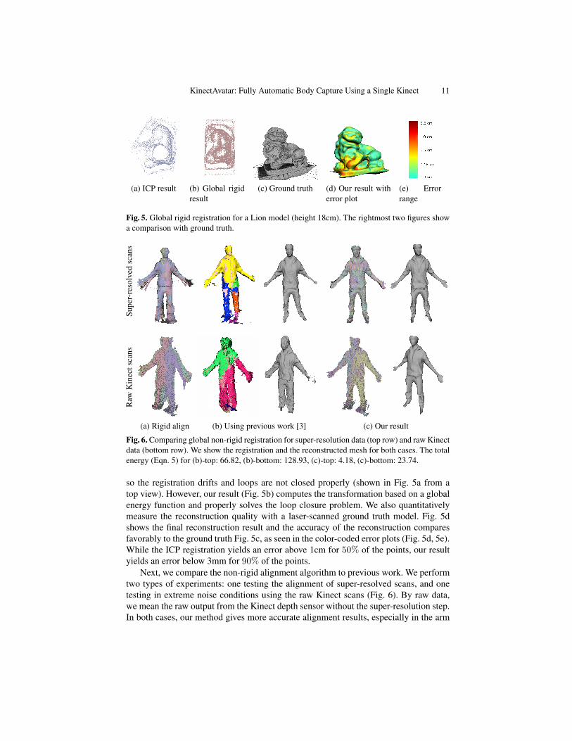
Fig. 5. Global rigid registration for a Lion model (height 18cm). The rightmost two figures showa comparison with ground truth.
Supe
r-re
solv
edsc
ans
Raw
Kin
ects
cans
(a) Rigid align (b) Using previous work [3] (c) Our result
Fig. 6. Comparing global non-rigid registration for super-resolution data (top row) and raw Kinectdata (bottom row). We show the registration and the reconstructed mesh for both cases. The totalenergy (Eqn. 5) for (b)-top: 66.82, (b)-bottom: 128.93, (c)-top: 4.18, (c)-bottom: 23.74.
so the registration drifts and loops are not closed properly (shown in Fig. 5a from atop view). However, our result (Fig. 5b) computes the transformation based on a globalenergy function and properly solves the loop closure problem. We also quantitativelymeasure the reconstruction quality with a laser-scanned ground truth model. Fig. 5dshows the final reconstruction result and the accuracy of the reconstruction comparesfavorably to the ground truth Fig. 5c, as seen in the color-coded error plots (Fig. 5d, 5e).While the ICP registration yields an error above 1cm for 50% of the points, our resultyields an error below 3mm for 90% of the points.
Next, we compare the non-rigid alignment algorithm to previous work. We performtwo types of experiments: one testing the alignment of super-resolved scans, and onetesting in extreme noise conditions using the raw Kinect scans (Fig. 6). By raw data,we mean the raw output from the Kinect depth sensor without the super-resolution step.In both cases, our method gives more accurate alignment results, especially in the arm
12 Yan Cui, Will Chang, Tobias Noll, Didier Stricker
Mes
hFr
ont
Text
ure
Fron
tM
esh
Bac
kTe
xtur
eB
ack
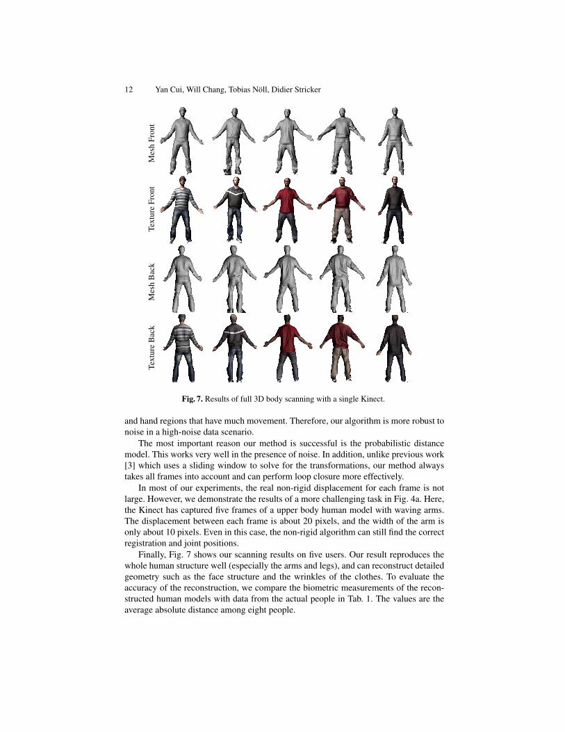
Fig. 7. Results of full 3D body scanning with a single Kinect.
and hand regions that have much movement. Therefore, our algorithm is more robust tonoise in a high-noise data scenario.
The most important reason our method is successful is the probabilistic distancemodel. This works very well in the presence of noise. In addition, unlike previous work[3] which uses a sliding window to solve for the transformations, our method alwaystakes all frames into account and can perform loop closure more effectively.
In most of our experiments, the real non-rigid displacement for each frame is notlarge. However, we demonstrate the results of a more challenging task in Fig. 4a. Here,the Kinect has captured five frames of a upper body human model with waving arms.The displacement between each frame is about 20 pixels, and the width of the arm isonly about 10 pixels. Even in this case, the non-rigid algorithm can still find the correctregistration and joint positions.
Finally, Fig. 7 shows our scanning results on five users. Our result reproduces thewhole human structure well (especially the arms and legs), and can reconstruct detailedgeometry such as the face structure and the wrinkles of the clothes. To evaluate theaccuracy of the reconstruction, we compare the biometric measurements of the recon-structed human models with data from the actual people in Tab. 1. The values are theaverage absolute distance among eight people.
KinectAvatar: Fully Automatic Body Capture Using a Single Kinect 13
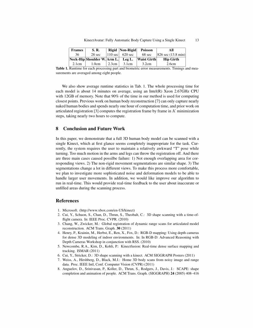
Frames S. R. Rigid Non-Rigid Poisson All36 28 sec 110 sec 620 sec 68 sec 826 sec (13.8 min)
Neck-Hip Shoulder W. Arm L. Leg L. Waist Girth Hip Girth2.1cm 1.0cm 2.3cm 3.1cm 3.2cm 2.6cm
Table 1. Runtime for each processing part and biometric error measurements. Timings and mea-surements are averaged among eight people.
We also show average runtime statistics in Tab. 1. The whole processing time foreach model is about 14 minutes on average, using an Intel(R) Xeon 2.67GHz CPUwith 12GB of memory. Note that 90% of the time in our method is used for computingclosest points. Previous work on human body reconstruction [7] can only capture nearlynaked human bodies and spends nearly one hour of computation time, and prior work onarticulated registration [3] computes the registration frame by frame in K minimizationsteps, taking nearly two hours to compute.
8 Conclusion and Future Work
In this paper, we demonstrate that a full 3D human body model can be scanned with asingle Kinect, which at first glance seems completely inappropriate for the task. Cur-rently, the system requires the user to maintain a relatively awkward “T” pose whileturning. Too much motion in the arms and legs can throw the registration off. And thereare three main cases caused possilbe failure: 1) Not enough overlapping area for cor-responding views. 2) The non-rigid movement segmentations are similar shape. 3) Thesegmentations change a lot in different views. To make this process more comfortable,we plan to investigate more sophisticated noise and deformation models to be able tohandle larger user movements. In addition, we would like improve our algorithm torun in real-time. This would provide real-time feedback to the user about inaccurate orunfilled areas during the scanning process.
References
1. Microsoft. (http://www.xbox.com/en-US/kinect)2. Cui, Y., Schuon, S., Chan, D., Thrun, S., Theobalt, C.: 3D shape scanning with a time-of-
flight camera. In: IEEE Proc. CVPR. (2010)3. Chang, W., Zwicker, M.: Global registration of dynamic range scans for articulated model
reconstruction. ACM Trans. Graph. 30 (2011)4. Henry, P., Krainin, M., Herbst, E., Ren, X., Fox, D.: RGB-D mapping: Using depth cameras
for dense 3D modeling of indoor environments. In: In RGB-D: Advanced Reasoning withDepth Cameras Workshop in conjunction with RSS. (2010)
5. Newcombe, R.A., Kim, D., Kohli, P.: Kinectfusion: Real-time dense surface mapping andtracking. ISMAR (2011)
6. Cui, Y., Stricker, D.: 3D shape scanning with a kinect. ACM SIGGRAPH Posters (2011)7. Weiss, A., Hirshberg, D., Black, M.J.: Home 3D body scans from noisy image and range
data. Proc. IEEE Intl, Conf. Computer Vision (CVPR) (2011)8. Anguelov, D., Srinivasan, P., Koller, D., Thrun, S., Rodgers, J., Davis, J.: SCAPE: shape
completion and animation of people. ACM Trans. Graph. (SIGGRAPH) 24 (2005) 408–416
14 Yan Cui, Will Chang, Tobias Noll, Didier Stricker
9. Tong, J., Zhou, J., Liu, L., Pan, Z., Yan, H.: Scanning 3d full human bodies using kinects.IEEE Transactions on Visualization and Computer Graphics (Proc. IEEE Virtual Reality), toappear. (2012)
10. Tomasi, C., Manduchi, R.: Bilateral filtering for gray and color images. In: Proceedings ofthe Sixth International Conference on Computer Vision. (1998)
11. Schuon, S., Theobalt, C., Davis, J., Thrun, S.: Lidarboost: Depth superresolution for ToF 3Dshape scanning. Proc. CVPR (2009)
12. Besl, P.J., McKay, N.D.: A method for registration of 3-D shapes. IEEE PAMI. 14 (1992)239–256
13. Benjemaa, R., Schmitt, F.: A solution for the registration of multiple 3D point sets using unitquaternions. In: Proc. ECCV. (1998) 34–50
14. Bergevin, R., Soucy, M., Gagnon, H., Laurendeau, D.: Towards a general multi-view regis-tration technique. IEEE PAMI 18 (1996) 540–547
15. Weise, T., Wismer, T., Leibe, B., Gool, L.V.: Online loop closure for real-time interactive 3Dscanning. Computer Vision and Image Understanding 115 (2011)
16. Mitra, N.J., Flory, S., Ovsjanikov, M., Gelfand, N., Guibas, L., Pottmann, H.: Dynamicgeometry registration. In: Symposium on Geometry Processing. (2007) 173–182
17. Huang, Q., Adams, B., Wicke, M., Guibas, L.: Non-rigid registration under isometric defor-mations. Computer Graphics Forum 27 (2008) 1449–1457
18. Wand, M., Adams, B., Ovsjanikov, M., Berner, A., Bokeloh, M., Jenke, P., Guibas, L., Seidel,H.P., Schilling, A.: Efficient reconstruction of non-rigid shape and motion from real-time 3Dscanner data. ACM Trans. Graph. (2009)
19. Popa, T., South-Dickinson, I., Bradley, D., Sheffer, A., Heidrich, W.: Globally consistentspace-time reconstruction. Computer Graphics Forum (Proceedings of SGP) 29 (2010)
20. Li, H., Luo, L., Vlasic, D., Peers, P., Popovic, J., Pauly, M., Rusinkiewicz, S.: Temporallycoherent completion of dynamic shapes. ACM Trans. Graph. 31 (2012)
21. Tevs, A., Berner, A., Wand, M., Ihrke, I., Bokeloh, M., Kerber, J., Seidel, H.P.: Animationcartography - intrinsic reconstruction of shape and motion. (ACM Trans. Graph. (to appear))
22. Kazhdan, M., Bolitho, M., Hoppe, H.: Poisson surface reconstruction. In: Proceedings ofthe Fourth Eurographics Symposium on Geometry Processing. SGP ’06 (2006) 61–70
23. Cui, Y., Schuon, S., Thrun, S., Stricke, D., Theobalt, C.: Algorithms for 3D shape scanningwith a depth camera. IEEE T-PAMI (2012)
24. Weickert, J., Hagen, H.E.: Visualization and Processing of Tensor Fields. Springer, Berlin(2006)
25. Myronenko, A., Song, X., Carreira-Perpinan, M.: Non-rigid point set registration: CoherentPoint Drift. NIPS 19 (2007) 1009
26. Murray, R.M., Li, Z., Sastry, S.S.: A Mathematical Introduction to Robotic Manipulation.CRC (1994)
27. Rosenhahn, B.: Pose estimation revisited. PhD thesis, Universitat Kiel (2003)28. Cui, Y., Hildenbrand, D.: Pose estimation based on geometric algebra. In: GraVisMa. (2009)29. Boykov, Y., Kolmogorov, V.: An experimental comparison of min-cut/max-flow algorithms
for energy minimization in vision. IEEE PAMI 26 (2004) 1124–113730. Sander, P.V., Wood, Z.J., Gortler, S.J., Snyder, J., Hoppe, H.: Multi-chart geometry images.
In: Proceedings of the Eurographics/ACM SIGGRAPH Symposium on Geometry Process-ing. SGP (2003) 146–155
31. Noll, T., Stricker, D.: Efficient packing of arbitrary shaped charts for automatic texture atlasgeneration. Computer Graphics Forum 30 (2011) 1309–1317