Kinder Morgan Terminals Deepwater Terminal Coal Handling...
50
Kinder Morgan Terminals Deepwater Terminal Coal Handling Project Pasadena, Texas Medium-Voltage Metal-Enclosed Switchgear 5547004-31100-16347-B_Spec-Section-16347-Medium Voltage Metal Enclosed Switchgear.doc Page 11 of 17 10. The relay shall be suitable for operating on control power with a nominal input voltage of 48 to 250 volts DC or 12 to 240 volts AC (50 or 60 hertz). In addition to control power transformer herein specified, a Dual-Source power supply shall be included to supply control power to protective devices. The Dual-Source power supply derives its power from the main current transformers. In the event of a fault that causes the loss of the normal control power, the Dual- Source power supply will maintain voltage at the critical moment when tripping is needed. 2.08 LOAD INTERRUPTER SWITCHES A. Each load interrupter switch shall have a manual over-toggle type mechanism that does not require the use of a chain or a cable for operation, and utilizes a heavy-duty coil spring to provide opening and closing action. The speed of opening and closing the switch shall be independent of the operator, and it shall be impossible to tease the switch into any intermediate position. B. The interrupter switch shall have separate main and break contacts to provide maximum endurance for fault close and load interrupting duty. C. The interrupter switch shall have insulating barriers between each phase and between the outer phases and the enclosure. D. A maintenance provision shall be provided for slow closing the switch to check switch-blade engagement and slow opening the switch to check operation of the arc interrupting contacts. E. For fused switch cubicles, fault protection shall be furnished by fuses as shown in the CONTRACT DOCUMENTS. The fuses shall have a minimum interrupting rating of 50,000 amperes symmetrical at 5 kV and shall be current limiting type with three (3) spare fuses for each fused switch. F. Units shall be two (2) high per section. 2.09 AUXILIARY DEVICES A. Ring type current transformers shall be furnished. The thermal and mechanical ratings of the current transformers shall be coordinated with the circuit breakers. Their accuracy rating shall be equal to or higher than ANSI standard requirements. The standard location for the current transformers on the bus side and line side of the breaker units shall be front accessible to permit adding or changing current transformers without
Transcript of Kinder Morgan Terminals Deepwater Terminal Coal Handling...

Kinder Morgan Terminals Deepwater Terminal Coal Handling Project Pasadena, Texas Medium-Voltage Metal-Enclosed Switchgear
5547004-31100-16347-B_Spec-Section-16347-Medium Voltage Metal Enclosed Switchgear.doc Page 11 of 17
10. The relay shall be suitable for operating on control power with a nominal input voltage of 48 to 250 volts DC or 12 to 240 volts AC (50 or 60 hertz). In addition to control power transformer herein specified, a Dual-Source power supply shall be included to supply control power to protective devices. The Dual-Source power supply derives its power from the main current transformers. In the event of a fault that causes the loss of the normal control power, the Dual-Source power supply will maintain voltage at the critical moment when tripping is needed.
2.08 LOAD INTERRUPTER SWITCHES
A. Each load interrupter switch shall have a manual over-toggle type mechanism that does not require the use of a chain or a cable for operation, and utilizes a heavy-duty coil spring to provide opening and closing action. The speed of opening and closing the switch shall be independent of the operator, and it shall be impossible to tease the switch into any intermediate position.
B. The interrupter switch shall have separate main and break contacts to
provide maximum endurance for fault close and load interrupting duty.
C. The interrupter switch shall have insulating barriers between each phase and between the outer phases and the enclosure.
D. A maintenance provision shall be provided for slow closing the switch to
check switch-blade engagement and slow opening the switch to check operation of the arc interrupting contacts.
E. For fused switch cubicles, fault protection shall be furnished by fuses as
shown in the CONTRACT DOCUMENTS. The fuses shall have a minimum interrupting rating of 50,000 amperes symmetrical at 5 kV and shall be current limiting type with three (3) spare fuses for each fused switch.
F. Units shall be two (2) high per section.
2.09 AUXILIARY DEVICES
A. Ring type current transformers shall be furnished. The thermal and
mechanical ratings of the current transformers shall be coordinated with the circuit breakers. Their accuracy rating shall be equal to or higher than ANSI standard requirements. The standard location for the current transformers on the bus side and line side of the breaker units shall be front accessible to permit adding or changing current transformers without

Kinder Morgan Terminals Deepwater Terminal Coal Handling Project Pasadena, Texas Medium-Voltage Metal-Enclosed Switchgear
5547004-31100-16347-B_Spec-Section-16347-Medium Voltage Metal Enclosed Switchgear.doc Page 12 of 17
removing high-voltage insulation connections. Shorting terminal blocks shall be furnished on the secondary of all the current transformers.
B. Voltage and control power transformers of the quantity and ratings indicated in the CONTRACT DOCUMENTS shall be supplied. Voltage transformers shall be mounted in drawout drawers contained in an enclosed auxiliary compartment. Control power transformers up to 5kV, 15 kVA, single-phase shall be mounted in drawout drawers. Rails shall be provided as applicable for each drawer to permit easy inspection, testing and fuse replacement. Shutters shall isolate primary bus stabs when drawers are withdrawn.
C. A mechanical interlock shall be provided to require the secondary breaker to be open before the CPT drawer or CPT primary fuse drawer can be withdrawn.
D. 12.47kV power factor correcting capacitors shall be included as shown on
the contract drawings. 2.10 ENCLOSURES
A. The switchgear described in these specifications shall be weatherproof, sheltered-aisle construction for outdoor service. Each shipping group shall be mounted upon an integral base frame with a weatherproof enclosure assembly in the field into a complete metal enclosed switchgear assembly. The enclosure shall be extended on the breaker drawout side to form an operating and/or maintenance aisle large enough to permit interchange of circuit breakers. A weatherproof door with an inside quick release latch mechanism shall be located at each end of the inside even when locked on the outside. Interior lights, light switches and duplex ground fault receptacles shall be furnished in the aisle.
B. Each vertical section of switchgear shall be provided with space heaters. Tubular type heaters operated at half voltage for long life shall be supplied. 500-volt or 250-volt rated heaters shall be used at 240 or 120-volt, respectively.
C. The finish shall consist of a coat of gray (ANSI-61), thermosetting, polyester powder paint applied electrostatically to pre-cleaned and phosphatized steel and aluminum for internal and external parts. The coating is to have a thickness of not less than 1.5 mils. The finish shall have the following properties: 1. Impact resistance (ASTM D-2794) 60 direct/60 indirect 2. Pencil hardness (ASTM D-3363) H
Kinder Morgan Terminals Deepwater Terminal Coal Handling Project Pasadena, Texas Medium-Voltage Metal-Enclosed Switchgear
5547004-31100-16347-B_Spec-Section-16347-Medium Voltage Metal Enclosed Switchgear.doc Page 13 of 17
3. Flexibility (ASTM D-522) Pass 1/8-inch mandrel 4. Salt spray (ASTM B117-85 [20]) 600 hours 5. Color ANSI 61 gray
D. External openings shall be screened to prevent the entrance of small
animals
2.11 NAMEPLATES A. Engraved nameplates, mounted on the face of the assembly, shall be
furnished for all main and feeder circuits as indicated in CONTRACT DOCUMENTS. Nameplates shall be laminated plastic, black characters on white background, and secured with stainless steel hardware. Characters shall be 3/16-inch high, minimum. Furnish master nameplate for each switchgear lineup giving information in accordance with IEEE Std. C37.20.2-1999, Section 7.4.1. Circuit nameplates shall be provided with circuit designations as shown on single-line diagrams.
B. Control components mounted within the assembly, such as fuse blocks, relays, pushbuttons, switches, etc., shall be suitably marked for identification corresponding to appropriate designations on manufacturer’s wiring diagrams.
2.12 ACCESSORIES A. Furnish accessories for test, inspection, maintenance and operation,
including: 1. One – Maintenance tool for manually charging the breaker closing
spring and manually opening the shutter 2. One – Levering crank for moving the breaker between test and
connected positions 3. One – Test jumper for electrically operating the breaker while out of
its compartment 4. One – Breaker lifting yoke used for attachment to breaker for lifting
breaker on or off compartment rails, when applicable 5. One – Set of rail extensions and rail clamps, when applicable 6. One – Portable lifting device for lifting the breaker on or off the rails 7. One – Test cabinet for testing electrically operated breakers outside
housing 8. One – Electrical levering device
2.13 CORONA FREE

Kinder Morgan Terminals Deepwater Terminal Coal Handling Project Pasadena, Texas Medium-Voltage Metal-Enclosed Switchgear
5547004-31100-16347-B_Spec-Section-16347-Medium Voltage Metal Enclosed Switchgear.doc Page 14 of 17
A. The switchgear shall be corona free by design and shall be tested for partial discharges in accordance with EEMAC standard G11-1. The corona discharges measured during the tests shall be less than 100 picocoulombs.
2.14 PARTIAL DISCHARGE SENSING EQUIPMENT A. The switchgear shall be equipped with factory installed partial discharge
sensors and relay for continuous monitoring of the partial discharges under normal operation. The purpose of partial discharge sensing is to identify potential insulation problems (insulation degradation) by trending of PD data over time so that corrective actions can be planned and implemented before permanent insulation deterioration develops.
B. The PD sensing and monitoring system shall consist of sensors and relay specifically developed for such applications, such as Eaton’s RFCT sensor and InsulGard relay, or equivalent. One RFCT sensor shall be installed over floating stress shields of specially designed bus or line side primary bushings, at every two vertical section for detection of partial discharges within the switchgear compartments. An RFCT sensor shall also be provided for installation around ground shields of the incoming or outgoing power cable termination for detection of PD activity in the cables up to 100 feet from the switchgear. Output signals from each RFCT shall be factory wired to PD monitoring relay for continuous monitoring.
2.15 EQUIPMENT METERING
A. Provide a line Meter Monitor and Protection (MM&P) device. The MM&P shall provide the metering functions with % of full scale accuracy as indicated, and auto range between units, kilounits and megaunits. The MM&P shall provide the adjustable protection functions indicated. The MM & P shall be UL listed, cUL and CE certified and also meet ANSI standard C37.90.1 for surge withstand. The meter shall be equipped to communicate via Ethernet/IP.
Kinder Morgan Terminals Deepwater Terminal Coal Handling Project Pasadena, Texas Medium-Voltage Metal-Enclosed Switchgear
5547004-31100-16347-B_Spec-Section-16347-Medium Voltage Metal Enclosed Switchgear.doc Page 15 of 17
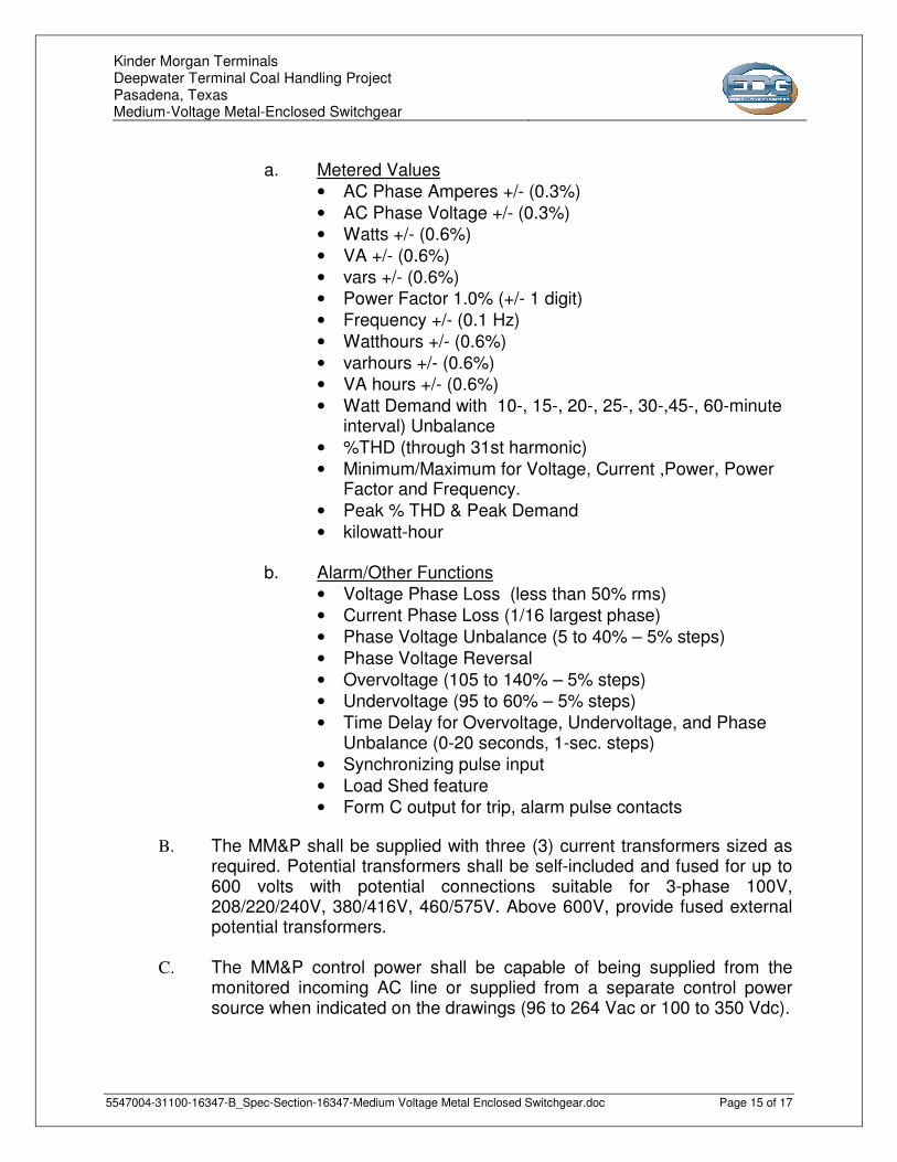
a. Metered Values
• AC Phase Amperes +/- (0.3%)
• AC Phase Voltage +/- (0.3%) • Watts +/- (0.6%)
• VA +/- (0.6%)
• vars +/- (0.6%) • Power Factor 1.0% (+/- 1 digit)
• Frequency +/- (0.1 Hz)
• Watthours +/- (0.6%)
• varhours +/- (0.6%) • VA hours +/- (0.6%)
• Watt Demand with 10-, 15-, 20-, 25-, 30-,45-, 60-minute interval) Unbalance
• %THD (through 31st harmonic)
• Minimum/Maximum for Voltage, Current ,Power, Power Factor and Frequency.
• Peak % THD & Peak Demand
• kilowatt-hour
b. Alarm/Other Functions
• Voltage Phase Loss (less than 50% rms) • Current Phase Loss (1/16 largest phase)
• Phase Voltage Unbalance (5 to 40% – 5% steps)
• Phase Voltage Reversal
• Overvoltage (105 to 140% – 5% steps) • Undervoltage (95 to 60% – 5% steps)
• Time Delay for Overvoltage, Undervoltage, and Phase Unbalance (0-20 seconds, 1-sec. steps)
• Synchronizing pulse input
• Load Shed feature • Form C output for trip, alarm pulse contacts
B. The MM&P shall be supplied with three (3) current transformers sized as required. Potential transformers shall be self-included and fused for up to 600 volts with potential connections suitable for 3-phase 100V, 208/220/240V, 380/416V, 460/575V. Above 600V, provide fused external potential transformers.
C. The MM&P control power shall be capable of being supplied from the monitored incoming AC line or supplied from a separate control power source when indicated on the drawings (96 to 264 Vac or 100 to 350 Vdc).

Kinder Morgan Terminals Deepwater Terminal Coal Handling Project Pasadena, Texas Medium-Voltage Metal-Enclosed Switchgear
5547004-31100-16347-B_Spec-Section-16347-Medium Voltage Metal Enclosed Switchgear.doc Page 16 of 17
PART 3 – EXECUTION 3.01 INSTALLATION
A. Install all equipment per the manufacturer’s recommendations and CONTRACT DOCUMENTS.
B. Provide all necessary hardware to secure the assembly in place
3.02 FACTORY TESTING
A. The following standard factory tests shall be performed on the circuit breaker element provided under this section. All tests shall be in accordance with the latest version of ANSI and NEMA standards.
1. Circuit breaker operated over the range of minimum to maximum
control voltage. 2. Factory setting of contact gap. 3. One (1) minute dielectric test per ANSI standards. 4. Alignment test with master cell to verify all interfaces and
interchangeability. 5. Final inspections and quality checks.
B. The following production test shall be performed on each circuit breaker housing:
1. One (1) minute dielectric test per ANSI standards on primary and
secondary circuits. 2. Operation of wiring, relays and other devices verified by an
operational sequence test. 3. Alignment test with master breaker to verify interfaces 4. Final inspection and quality check.
C. The manufacturer shall provide three (3) certified copies of factory test
reports.
D. Factory tests may be witnessed by the OWNER. 1. Notify the OWNER minimum two (2) weeks prior to the date the
tests are to be performed.
3.02 FIELD QUALITY CONTROL
A. Provide the services of a qualified factory-trained manufacturer's representative to assist in installation and start-up of the equipment specified under this section for a period of 3 working days at the
Kinder Morgan Terminals Deepwater Terminal Coal Handling Project Pasadena, Texas Medium-Voltage Metal-Enclosed Switchgear
5547004-31100-16347-B_Spec-Section-16347-Medium Voltage Metal Enclosed Switchgear.doc Page 17 of 17
manufacturing site of the engineered prefabricated building and for a period of 3 working days at the project site. The manufacturer's representative shall provide technical direction and assistance in general assembly of the equipment, connections and adjustments, and testing of the assembly and components contained therein.
B. Provide three (3) copies of the manufacturer's field
start-up report.
3.03 FIELD ADJUSTMENTS
A. The relays shall be set in the field by a qualified representative of the manufacturer in accordance with settings designated in a coordination study of the system as required in the CONTRACT DOCUMENTS.
3.04 MANUFACTURER'S CERTIFICATION
A. A qualified factory-trained manufacturer's representative shall certify in writing that the equipment has been installed, adjusted and tested in accordance with the manufacturer's recommendations.
B. Provide three (3) copies of the manufacturer's representative's
certification.
3.05 TRAINING
A. Provide a training session for up to 4 owner's representatives for 1 normal workday at the project site.
B. The training session shall be conducted by a manufacturer's qualified
representative and consist of instruction on the operation of switches, circuit breaker(s), protective devices, and other major components.
END OF SECTION
KINDER MORGAN TERMINALS
DEEPWATER TERMINAL COAL HANDLING PROJECT
PASADENA, TEXAS
SECTION 16460
DRY TYPE TRANSFORMERS - 480 VOLT AND BELOW
Rev Description Date Prepared Reviewed Approved
A Issued for Review 24 Oct 2012 W. Albanese J. Crane A. Holtom
B Issued for Bid 07 Dec 2012 W. Albanese J. Crane A. Holtom
EDG Job No. 5547.004
EDG Document No. 5547004-31100-16460

Kinder Morgan Terminals Deepwater Terminal Coal Handling Project Pasadena, Texas Dry Type Transformers - 480 VOLT and Below
5547004-31100-16460-B_Spec-Section-16460-Dry Type Transformers 480 Volt and Below.doc Page 2 of 3
PART 1 - GENERAL 1.01 SCOPE
A. Furnish and install dry type ventilated transformers for all distribution transformers as required on the Contract Drawings and specified herein.
1.02 SUBMITTALS
A. Submit shop drawings to Construction Manager for approval prior to installation. 1.03 DEFINITIONS
A. OWNER: Kinder Morgan Terminals B. ENGINEER: EDG C. CONTRACTOR: entity responsible for the work D. CONTRACT DOCUMENTS: Project Specifications, Project Drawings, Project Bid
Documents, and contractual signed and dated documents E. RECORD DOCUMENTS: CONTRACTOR marked up as provided CONTRACT
DOCUMENTS F. WORK: Labor and material G. FURNISH: supply and deliver to project site, ready for unloading, unpacking,
assembly, installation, and similar operations H. INSTALL: unload, temporarily store, protect, unpack, assemble, erect, place,
anchor, make complete and ready for intended use, and make fully operational I. PROVIDE: Furnish and Install J. INDICATED: cross-reference to graphic representations, notes, drawings,
specifications, and other documents K. REGULATIONS: : laws, ordinances, statues, lawful orders, decisions by the
authorities having jurisdiction, codes, and standards
PART 2 - PRODUCTS
2.01 TRANSFORMERS
A. Provide transformers that meet applicable NEMA, ANSI, and IEEE standards.
B. Provide transformers with KVA capacity, voltage, and phase as required.
C. Provide transformers that meet the following minimum requirements:
1. Two 5% FCBN taps for 15 KVA and below. 2. Two 2-1/2% FCAN taps and Four 2-1/2% FCBN taps for 25 KVA and
above. 3. Non-hygroscopic, thermosetting varnish that is vacuum impregnated on
transformer coils.

Kinder Morgan Terminals Deepwater Terminal Coal Handling Project Pasadena, Texas Dry Type Transformers - 480 VOLT and Below
5547004-31100-16460-B_Spec-Section-16460-Dry Type Transformers 480 Volt and Below.doc Page 3 of 3
4. Insulating system listed by UL with 115°C temperature rise Class H insulation.
5. Vibration absorbing mounts that isolate core and coil unit from the enclosure.
6. Maximum top of case temperature not exceeding 35°C above ambient at full load.
7. Core and coils visibly grounded to the transformer frame by a flexible-grounding strap of adequate size.
8. Capability of continuous operation at 100% rating in ambient of 40°C.
D. Provide transformers with COPPER COILS only. Aluminum coils are not acceptable.
E. Provide transformers as manufactured by General Electric, Square D Company,
or approved equal.
PART 3 – EXECUTION
3.01 INSTALLATION
A. Mount transformers on vibration isolators. B. For transformers designated to be mounted on elevated stands on the wall, use
mounting racks and brackets approved by the manufacturer for such application.
C. Ground transformers in accordance with NEC requirements and Section 16450: “Grounding and Bonding”.
END OF SECTION

KINDER MORGAN TERMINALS
DEEPWATER TERMINAL COAL HANDLING PROJECT
PASADENA, TEXAS
SECTION 16462
DISTRIBUTION SWITCHBOARD
Rev Description Date Prepared Reviewed Approved
A Issued for Review 24 Oct 2012 W.Albanese J. Crane A. Holtom
B Issued for Bid 07 Dec 2012 W.Albanese J. Crane A. Holtom
EDG Job No. 5547.004
EDG Document No. 5547004-31100-16462

Kinder Morgan Terminals Deepwater Terminal Coal Handling Project Pasadena, Texas Distribution Switchboard
5547004-31100-16462-B_Spec-Section-16462-Distribution Switchboards.doc Page 2 of 8
PART 1 - GENERAL 1.01 SCOPE
A. The Contractor shall furnish and install, where indicated, a free-standing, dead-front type low voltage distribution switchboard, utilizing group mounted circuit protective devices as specified herein, and as shown on the contract drawings.
1.02 REFERENCES
A. The low voltage distribution switchboards and all components shall be designed, manufactured and tested in accordance with the latest applicable following standards:
1. NEMA PB-2 2. UL Standard 891
1.03 DEFINITIONS
A. OWNER: Kinder Morgan Terminals B. ENGINEER: EDG C. CONTRACTOR: entity responsible for the work D. CONTRACT DOCUMENTS: Project Specifications, Project Drawings, Project Bid
Documents, and contractual signed and dated documents E. RECORD DOCUMENTS: CONTRACTOR marked up as provided CONTRACT
DOCUMENTS F. WORK: Labor and material G. FURNISH: supply and deliver to project site, ready for unloading, unpacking,
assembly, installation, and similar operations H. INSTALL: unload, temporarily store, protect, unpack, assemble, erect, place,
anchor, make complete and ready for intended use, and make fully operational I. PROVIDE: Furnish and Install J. INDICATED: cross-reference to graphic representations, notes, drawings,
specifications, and other documents K. REGULATIONS: laws, ordinances, statues, lawful orders, decisions by the
authorities having jurisdiction, codes, and standards 1.04 SUBMITTALS – FOR REVIEW/APPROVAL
A. The following information shall be submitted to the Owner:
1. Master drawing index 2. Front view elevation 3. Floor plan

Kinder Morgan Terminals Deepwater Terminal Coal Handling Project Pasadena, Texas Distribution Switchboard
5547004-31100-16462-B_Spec-Section-16462-Distribution Switchboards.doc Page 3 of 8
4. Top view 5. Single line 6. Schematic diagram 7. Nameplate schedule 8. Component list 9. Conduit entry/exit locations 10. Assembly ratings including:
a) Short-circuit rating b) Voltage
c) Continuous current
11. Major component ratings including:
a) Voltage
b) Continuous current
c) Interrupting ratings
12. Cable terminal sizes 13. Product data sheets
B. Where applicable, the following additional information shall be submitted to the
Owner:
1. Busway connection 2. Connection details between close-coupled assemblies 3. Composite floor plan of close-coupled assemblies 4. Key interlock scheme drawing and sequence of operations
1.05 SUBMITTALS – FOR CONSTRUCTION
A. The following information shall be submitted for record purposes:
1. Final as-built drawings and information for items listed in Paragraph 1.04, and shall incorporate all changes made during the manufacturing process
Kinder Morgan Terminals Deepwater Terminal Coal Handling Project Pasadena, Texas Distribution Switchboard
5547004-31100-16462-B_Spec-Section-16462-Distribution Switchboards.doc Page 4 of 8
2. Wiring diagrams 3. Certified production test reports 4. Installation information 5. Seismic certification and equipment anchorage details as specified
1.06 QUALIFICATIONS
A. The manufacturer of the assembly shall be the manufacturer of the major components within the assembly.
1.07 REGULATORY REQUIREMENTS
A. The switchboard shall be UL labeled. 1.08 DELIVERY, STORAGE AND HANDLING
A. Equipment shall be handled and stored in accordance with manufacturer’s instructions. One (1) copy of these instructions shall be included with the equipment at time of shipment.
1.09 OPERATION AND MAINTENANCE MANUALS
A. Equipment operation and maintenance manuals shall be provided with each assembly shipped and shall include instruction leaflets, instruction bulletins and renewal parts lists where applicable, for the complete assembly and each major component.
PART 2 - PRODUCTS 2.01 APPROVED MANUFACTURERS
A. Eaton, General Electric, Square-D.
2.02 RATINGS
A. The assembly shall be rated to withstand mechanical forces exerted during short-circuit conditions when connected directly to a power source having available fault current as shown on the drawings at rated voltage.
B. Voltage rating to be as indicated on the drawings.
2.03 CONSTRUCTION
A. Switchboard shall consist of the required number of vertical sections bolted together to form a rigid assembly. The sides and rear shall be covered with

Kinder Morgan Terminals Deepwater Terminal Coal Handling Project Pasadena, Texas Distribution Switchboard
5547004-31100-16462-B_Spec-Section-16462-Distribution Switchboards.doc Page 5 of 8
removable bolt-on covers. All edges of front covers or hinged front panels shall be formed. Provide adequate ventilation within the enclosure.
B. All sections of the switchboard shall be rear aligned with depth as shown on the
drawings. All protective devices shall be group mounted. Devices shall be front removable and load connections front accessible enabling switchboard to be mounted against a wall.
C. The assembly shall be provided with adequate lifting means.
2.04 BUS
A. All bus bars shall be silver-plated copper. Main horizontal bus bars shall be mounted with all three phases arranged in the same vertical plane. Bus sizing shall be based on NEMA standard temperature rise criteria of 65 degrees C over a 40 degrees C ambient (outside the enclosure).
B. Provide a full capacity neutral bus where a neutral bus is indicated on the
drawings.
C. A copper ground bus (minimum 1/4 x 2 inch) shall be furnished firmly secured to each vertical section structure and shall extend the entire length of the switchboard.
D. All hardware used on conductors shall be high-tensile strength and zinc-plated. All
bus joints shall be provided with conical spring-type washers. 2.05 WIRING/TERMINATIONS
A. Small wiring, necessary fuse blocks and terminal blocks within the switchboard shall be furnished as required. Control components mounted within the assembly, such as fuse blocks, relays, pushbuttons, switches, etc., shall be suitably marked for identification corresponding to appropriate designations on manufacturer’s wiring diagrams.
B. Mechanical-type terminals shall be provided for all line and load terminations
suitable for copper or aluminum cable rated for 75 degrees C of the size as indicated on the drawings.
C. Lugs shall be provided in the incoming line section for connection of the main
grounding conductor. Additional lugs for connection of other grounding conductors shall be provided as indicated on the drawings.
D. All control wire shall be type SIS, bundled and secured with nylon ties. Insulated
locking spade terminals shall be provided for all control connections, except where saddle type terminals are provided integral to a device. All current transformer secondary leads shall first be connected to conveniently accessible short-circuit terminal blocks before connecting to any other device. All groups of control wires
Kinder Morgan Terminals Deepwater Terminal Coal Handling Project Pasadena, Texas Distribution Switchboard
5547004-31100-16462-B_Spec-Section-16462-Distribution Switchboards.doc Page 6 of 8
leaving the switchboard shall be provided with terminal blocks with suitable numbering strips. Provide wire markers at each end of all control wiring.
2.06 MAIN PROTECTIVE DEVICES
A. Protective devices shall be molded case circuit breakers with inverse time and instantaneous tripping characteristics.
B. Circuit breakers shall be operated by a toggle-type handle and shall have a quick-
make, quick-break over-center switching mechanism that is mechanically trip-free. Automatic tripping of the breaker shall be clearly indicated by the handle position. Contacts shall be nonwelding silver alloy and arc extinction shall be accomplished by means of DE-ION arc chutes. A push-to-trip button on the front of the circuit breaker shall provide a local manual means to exercise the trip mechanism.
C. Circuit breakers shall have a minimum symmetrical interrupting capacity as
indicated on the drawings.
D. Circuit breakers 1600-ampere through 2500-ampere frame shall have a microprocessor-based rms sensing trip units.
E. Ground fault protection shall be provided where indicated.
2.07 TRIP UNITS
A. Each molded case circuit breaker microprocessor-based tripping system shall consist of three (3) current sensors, a trip unit and a flux-transfer shunt trip. The trip unit shall use microprocessor-based technology to provide the adjustable time-current protection functions. True rms sensing circuit protection shall be achieved by analyzing the secondary current signals received from the circuit breaker current sensors, and initiating trip signals to the circuit breaker trip actuators when predetermined trip levels and time-delay settings are reached.
B. An adjustable trip setting dial mounted on the front of the trip unit, or
interchangeable ratings plugs shall establish the continuous trip ratings of each circuit breaker. Rating plugs shall be fixed or adjustable as indicated. Rating plugs shall be interlocked so they are not interchangeable between frames, and interlocked such that a breaker cannot be closed and latched with the rating plug removed.
C. System coordination shall be provided by the following microprocessor-based
time-current curve shaping adjustments:
1. Adjustable long-time setting (set by adjusting the trip setting dial or rating plug)
2. Adjustable short-time setting and delay with selective curve shaping
3. Adjustable instantaneous setting
Kinder Morgan Terminals Deepwater Terminal Coal Handling Project Pasadena, Texas Distribution Switchboard
5547004-31100-16462-B_Spec-Section-16462-Distribution Switchboards.doc Page 7 of 8
4. Adjustable ground fault setting and delay
D. The microprocessor-based trip unit shall have both powered and unpowered thermal memory to provide protection against cumulative overheating should a number of overload conditions occur in quick succession.
E. When the adjustable instantaneous setting is omitted, the trip unit shall be provided
with an instantaneous override. F. Where internal ground fault protection is specified, adjustable settings shall not
exceed 1200 amperes. Provide neutral ground fault sensor for four-wire loads. G. Breakers shall have built-in test points for testing the long-time delay,
instantaneous, and ground fault functions of the breaker by means of a test set. 2.08 ACCESSORIES
A. Provide shunt trips as shown on the contract drawings. 2.09 Power Monitor
A. Provide an electrical power monitor as specified in section 16291. 2.10 ENCLOSURES
A. NEMA 1 Enclosure 2.11 NAMEPLATES
A. Engraved nameplates, mounted on the face of the assembly, shall be furnished for all main and feeder circuits as indicated on the drawings. Nameplates shall be laminated plastic, black characters on white background. Characters shall be 3/16-inch high, minimum. Nameplates shall give item designation and circuit number as well as frame ampere size and appropriate trip rating. Furnish master nameplate giving switchboard designation, voltage ampere rating, short-circuit rating, manufacturer’s name, general order number, and item number.
B. Control components mounted within the assembly, such as fuse blocks, relays,
pushbuttons, switches, etc., shall be suitably marked for identification corresponding to appropriate designations on manufacturer’s wiring diagrams.
2.12 FINISH
A. All exterior and interior steel surfaces of the switchboard shall be properly cleaned and provided with a rust-inhibiting phosphatized coating. Color and finish of the switchboard shall be ANSI 61 light gray.
2.13 TRANSIENT VOLTAGE SURGE SUPPRESSION

Kinder Morgan Terminals Deepwater Terminal Coal Handling Project Pasadena, Texas Distribution Switchboard
5547004-31100-16462-B_Spec-Section-16462-Distribution Switchboards.doc Page 8 of 8
A. Provide transient voltage surge suppression as specified in Section 16671. PART 3 – EXECUTION 3.01 FACTORY TESTING
A. The following standard factory tests shall be performed on the equipment provided under this section. All tests shall be in accordance with the latest version of ANSI and NEMA standards.
1. The switchboard shall be completely assembled, wired, adjusted, and tested at
the factory. After assembly, the complete switchboard will be tested for operation under simulated service conditions to ensure the accuracy of the wiring and the functioning of all equipment. The main circuits shall be given a dielectric test of 2200 volts for one (1) minute between live parts and ground, and between opposite polarities. The wiring and control circuits shall be given a dielectric test of 1500 volts for one (1) minute between live parts and ground
B. The manufacturer shall provide three (3) certified copies of factory test reports.
3.02 MANUFACTURER’S CERTIFICATION
A. A certified test report of all standard production tests shall be available to the Owner upon request.
3.03 INSTALLATION
A. The Contractors shall install all equipment per the manufacturer’s instructions, contract drawings and National Electrical Code.
B. The assembly shall be provided with adequate lifting means and shall be capable
of being moved into installation position and bolted directly to the floor without the use of floor sills provided the floor is level to 1/8 inch per 3-foot distance in any direction. All necessary hardware to secure the assembly in place shall be provided by the Contractor.
END OF SECTION

KINDER MORGAN TERMINALS
DEEPWATER TERMINAL COAL HANDLING PROJECT
PASADENA, TEXAS
SECTION 16480
480V MOTOR CONTROL CENTERS
Rev Description Date Prepared Reviewed Approved
A Issued for Review 24 Oct 2012 J. Crane T. Justice A. Holtom
B Issued for Bid 07 Dec 2012 J. Crane T. Justice A. Holtom
EDG Job No. 5547.004
EDG Document No. 5547004-31100-16480
Kinder Morgan Terminals Deepwater Terminal Coal Handling Project Pasadena, Texas 480V Motor Control Centers
5547004-31100-16480-B_Spec-Section-16480-480 Motor Control Centers.doc Page 2 of 23
PART 1 - GENERAL 1.01 SCOPE
A. This specification defines the minimum requirements for the design, fabrication, assembly, inspection, testing and painting of the 480V motor control center (MCC). 1.02 REFERENCES A. INDUSTRY CODES AND STANDARDS
Design, sizing, construction, testing and assembly of the MCC shall comply with the latest edition of the following as applicable, except where these standards are less stringent than the requirements of these specifications: 1. NEMA National Electrical Manufacturers Association 2. IEEE Institute of Electrical and Electronic Engineers 3. NEC National Electric Code 4. UL Underwriters Laboratories 5. NETA National Electrical Testing Association 6. OSHA Occupational Safety and Health Administration 7. ANSI American National Standards Institute
1.03 DEFINITIONS
A. OWNER: Kinder Morgan Terminals B. ENGINEER: EDG C. CONTRACTOR: entity responsible for the work D. CONTRACT DOCUMENTS: Project Specifications, Project Drawings, Project Bid
Documents, and contractual signed and dated documents E. RECORD DOCUMENTS: CONTRACTOR marked up as provided CONTRACT
DOCUMENTS F. WORK: Labor and material G. FURNISH: supply and deliver to project site, ready for unloading, unpacking,
assembly, installation, and similar operations H. INSTALL: unload, temporarily store, protect, unpack, assemble, erect, place,
anchor, make complete and ready for intended use, and make fully operational I. PROVIDE: Furnish and Install J. INDICATED: cross-reference to graphic representations, notes, drawings,
specifications, and other documents K. REGULATIONS: laws, ordinances, statues, lawful orders, decisions by the
authorities having jurisdiction, codes, and standards 1.04 DRAWINGS
A. The following drawings shall be considered as an integral part of these specifications:
1. EP-30: Electrical Room ER03 480V One Line

Kinder Morgan Terminals Deepwater Terminal Coal Handling Project Pasadena, Texas 480V Motor Control Centers
5547004-31100-16480-B_Spec-Section-16480-480 Motor Control Centers.doc Page 3 of 23
2. EP-31: Electrical Room ER04 480V One Line 3. EP-34: Electrical Room ER07 480V One Line 4. EP-35: Electrical Room ER08 480V One Line
1.05 GENERAL REQUIREMENTS
A. The MCC shall be so designed and constructed to operate indoors in a humidity and temperature controlled environment. This equipment shall operate without reduced ratings for a minimum service life of 20 years from the date of installation.
B. The following short-term conditions are possible when the switchgear building’s air conditioning/heating is NOT operating: 1. Maximum Ambient Temperature 100°F 2. Minimum Ambient Temperature 20°F 3. Maximum Relative Humidity 70 percent C. The 480V MCC line-ups shall be furnished by an approved qualified firm.
This shall include the design, fabrication, inspection, quality control, testing, storage, documentation, shipping and delivery, technical support and start-up assistance required, to the satisfaction of Owner, to obtain equipment which complies with all the requirements of these specifications.
D. VENDOR’s responsibilities shall include, but not be limited to, the design, fabrication, inspection, quality control, testing, storage, technical documentation, shipping and delivery, and providing competent personnel for technical support and startup assistance. E. VENDOR shall be responsible for fulfillment of the purchase order for the MCC,
and shall not assign any portion of the responsibility to other vendors, subcontractor’s or suppliers without prior written approval of Owner.
F. VENDOR shall be responsible for providing the data in accordance with these
specifications.
PART 2 - PRODUCTS 2.01 GENERAL A. The Motor Control Center shall be UL certified for Type 2 coordination and consist of pre-assembled groups of Motor Controllers, Circuit Breakers and
associated equipment as described in the contract drawings. The units shall be grouped as indicated on the drawings in one or more vertical sections and shall be completely metal enclosed with integral bus, and bolted together to form a rigid, free standing, sectionalized assembly. The Motor Control Center shall be designed and constructed to permit future additions of vertical sections and interchanging of units by the user.

Kinder Morgan Terminals Deepwater Terminal Coal Handling Project Pasadena, Texas 480V Motor Control Centers
5547004-31100-16480-B_Spec-Section-16480-480 Motor Control Centers.doc Page 4 of 23
B. The maximum ambient temperature of the switchgear building in which the MCC will be installed is 100oF. All internal wiring shall be compatible with the maximum temperatures to which they are exposed. The vendor shall certify that the maximum operating temperatures attained will not exceed the maximum ratings of the equipment components or purchaser’s wiring.
C. The Motor Control Center Bus Compartments, Wireways, Motor Starters and Circuit Breakers shall be enclosed and isolated from one another. This isolation shall be adequate to prevent any fault in any unit enclosure from being transmitted to or involving anything outside the involved unit enclosure. D. The Motor Control Center Component terminal connections, bus assembly connections and all wiring connections throughout the MCC shall be adequate for
the continuous rated current of the part and for passing the maximum stated fault current of the line side protective device without damage or the need for servicing. All fastening torque requirements shall be determined and used. This information shall be shipped with the MCC along with the manufacturer’s recommended
maintenance schedule. E. The design and construction of the Motor Control Center shall allow the repair or
replacement of all electrical parts (including buses and bus supports) with the MCC installed against a wall.
F. The MCC and all components shall be designed, manufactured and tested in
accordance with the latest applicable standards of NEMA, ANSI and UL 845. 2.02 MANUFACTURERS
A. Low Voltage 480V MCCs shall be Allen Bradley IntelliCenter Ethernet/IP MCCs or equivalent from Square-D or Siemens.
2.03 DESIGN REQUIREMENTS
A. STRUCTURE
1. The Motor Control Center vertical sections shall be totally enclosed, dead front, rigid, free-standing structures with heavy duty internal
mounting angles running continuously within the shipping block. The vertical sections shall be prepared for field assembly with similar vertical sections and shall be free from defects affecting fit or operation. 2. A removable steel lifting means shall be provided with each shipping block. 3. Structure and shipping block dimensions. A. Structure Depth - 20 inches B. Structure Width – 20 inches C. Structure Height - 90 inches

Kinder Morgan Terminals Deepwater Terminal Coal Handling Project Pasadena, Texas 480V Motor Control Centers
5547004-31100-16480-B_Spec-Section-16480-480 Motor Control Centers.doc Page 5 of 23
D. Maximum number of vertical sections per shipping block shall not exceed three (3) B. Removable end plates shall be used to cover the horizontal power bus and horizontal wireway openings on each end of the MCC. C. Each section shall be equipped with a removable one piece top plate to facilitate
field fabrication of cable entrances. D. All vertical sections metal work shall have rounded edges and be tightly fitted with
no visible air gaps. The sections shall be designed and manufactured to meet NEMA 1 gasketed enclosure requirements. All wireway and unit doors shall be gasketed.
E. Doors and covers shall be of rigid construction and attached to the vertical section
by means of concealed hinges. Each unit shall be provided with a removable door mounted on removable pin type hinges which allow the door to swing open at least 110 degrees. Doors shall be removable from any location in the center without disturbing any other doors. The unit doors shall be fastened to the stationary structure so that it can be closed to cover the unit space when the starter has been removed. The unit door shall be held closed with the minimum of a single quarter turn pawl latch designed to resist forces during fault conditions.
F. All structural metal parts shall undergo a multi-step cleaning, rinsing and painting process resulting in complete coverage of uniform thickness. This process shall be maintained and controlled by rigid quality control standards. G. Exterior surfaces shall be painted ANSI 61 light gray. Interior surfaces and plug-in units shall be high gloss white. The paint type and process shall meet UL 1332 for electrical equipment steel enclosures. H. All unpainted parts shall be plated for corrosion resistance. I. The design shall incorporate a sill of sufficient height to allow door to open with electrical rubber switchboard matting 3/8” thick laid out flat in front. J. The structure framework shall be made of 12 gauge formed steel channels. The subframes for the front and rear of each structure shall be welded. These subframes are then bolted to longitudinal members to form the complete frame which shall be rigid and self-supporting. Side, back and roof covers of 12 gauge steel shall be mounted with screw fasteners for easy removal. All doors shall be 14 gauge steel. K. Fasteners shall be corrosion resistant type 316 stainless steel. 2.04 WIREWAYS

Kinder Morgan Terminals Deepwater Terminal Coal Handling Project Pasadena, Texas 480V Motor Control Centers
5547004-31100-16480-B_Spec-Section-16480-480 Motor Control Centers.doc Page 6 of 23
A. Both top and bottom areas of each vertical section shall be designed for use as a horizontal wireway. Each wireway shall extend the full depth of the control center and provide a minimum of 90 square inches of unobstructed wiring space.
Adequate space for conduit and wiring to enter the top or bottom shall be provided without structural interference.
B. The upper and lower horizontal wireways shall not be less than nine (9) inches high and shall extend the length of the control center. C. The wireways shall be isolated from all bus work. D. Horizontal wireways shall have removable covers held in place with captive
screws. E. Each vertical section shall have a full height vertical wireway isolated from both horizontal and vertical buses. F. Vertical wireways shall be an integral part of each section and shall be independent of plug-in units. G. Vertical wireways shall be 9 inches wide and 7 inches deep and provided with a removable hinged door to provide access to wiring without disturbing energized units. Type B terminals shall not encroach on these dimensions. H. All metal edges in wireways shall be treated to prevent damage to wires. I. Vertical and horizontal wireway access shall be possible without opening starter enclosure. J. Construction of the wireways shall be such that a fish wire, pushed into the wiring trough at the top or bottom of the motor control center from a conduit cannot contact a horizontal or vertical bus member. K. Tie bars shall be installed in vertical wireways. 2.05 BUSES
A. The power bus system shall be tin plated copper, supported, braced and isolated by a bus support mold of a high strength, non tracking glass reinforced polyester (or approved equal) insulating material. The solid insulating material shall not exceed one percent moisture absorption characteristics by ASTM D570 test and shall have an arc resistance greater than 100 seconds by ASTM D495 tests.
B. Bus bracing shall be rated as shown on drawings, which at a minimum will be
42,000 A RMS symmetrical at a 20% Power Factor for a period of not less than 30 cycles.
C. The main horizontal bus shall be rated as shown on the drawings and shall be
installed in the top section of the MCC. The horizontal bus shall be mounted on

Kinder Morgan Terminals Deepwater Terminal Coal Handling Project Pasadena, Texas 480V Motor Control Centers
5547004-31100-16480-B_Spec-Section-16480-480 Motor Control Centers.doc Page 7 of 23
edge in a vertical plane in recessed channels of the bus support molding to protect against the accumulation of dust and tracking between phases.
D. The horizontal bus shall be continuously braced within each section and shall be continuous in each shipping block. E. The horizontal bus shall be so positioned in the motor control center to give full access to the top section of the motor control center for cable entry. F. The horizontal bus shall be connected at the shipping splits with a tin plated copper splice kit rated the same as the horizontal power bus amps. These splice bars shall have four (4) bolts per bar (i.e. two bolts in each end). Double stud bus clamp assemblies comprised of flat washers and preassembled nuts with conical washers shall be used. The splice bars shall be isolated by a support mold of a high strength, non-tracking solid insulating material. G. The splice connections shall be front accessible for servicing with a torque wrench. Torque values and maintenance intervals shall be supplied with the motor control centers. H. The location of all splices shall be indicated by a label located on the inside of the vertical wireway door. This label shall contain torque values and maintenance intervals as recommended by the manufacturer. I. The vertical bus shall be continuously braced and sandwiched in a high strength, non-tracking glass polyester molding with a polycarbonate molded cover. Each vertical bus bar shall be isolated from the other phases and the horizontal power bus. J. The vertical bus shall be tin plated copper rated 600 amps. K. The horizontal ground bus shall be tin plated copper located in the bottom horizontal wireways throughout the entire length of the motor control center. L. The horizontal ground bus shall have a continuous rating of 600 amps. The ground bus shall have three (3) sets of two 9/16 inch holes on 1-3/4 inch centers in incoming sections for connection of customers grounding lug. M The vertical bus at the stab locations and the plug in unit stabs shall be lubricated with Sanchem, Inc. “NO-OX-ID A SPECIAL”, General Electric Co. Cat. D50H47, or approved equal.
CAUTION: Care shall be taken to avoid wiping lubricant on insulating surfaces.
N. All bus joints shall be designed and constructed so that their temperature at full rating, after load cycling, does not exceed the bus temperature 12 inches from the joints by more than 20oC. Fastening means shall employ provisions to negate the effect of temperature cycling and bus material cold flow or creep.
Kinder Morgan Terminals Deepwater Terminal Coal Handling Project Pasadena, Texas 480V Motor Control Centers
5547004-31100-16480-B_Spec-Section-16480-480 Motor Control Centers.doc Page 8 of 23
2.06 MAIN INCOMING LINE COMPARTMENT
A. The main incoming line section shall be set up for top entry to be located in Section 1.
B. The main incoming line section shall have a incoming lug connections or main
circuit breaker as shown on the drawings.
C. A polycarbonate protective barrier shall be installed to reduce the hazard of accidental contact with incoming lugs whenever the door is open.
D. No horizontal wireway is permitted in the top of an incoming line compartment. 2.07 PLUG IN UNITS A. A plug in unit shall consist of a unit assembly, unit support pan and unit door assembly. B. Each plug in unit shall be supported and guided by a removable unit support pan, so that different unit arrangements are easily accomplished. The rearrangement of a unit support pan shall be accomplished without the use of tools. C. After insertion, each plug in unit shall be held in place by two (2) or more multi-turn latches, located at the front of the unit. At least one latch shall be located at the top of the insert and one at the bottom for front accessibility. D. The units shall be installable or removable without any danger of contact with energized conductors even in the event of slippage of tools. The line contacts shall be covered with a barrier or otherwise protected from accidental contact. Line side wiring shall be protected from mechanical or electrical damage from other parts of the units. E. Plug in units shall have the ability to withstand an internal arcing fault at the line terminals of the contactor at full rated fault current available without rupturing the enclosure or door or rupturing the plug in unit enclosure. F. Plug in units shall not contain holes larger than absolutely necessary for the entrance of conductors. The walls of the plug in units shall be designed to prevent the propagation of ionized arc products to other units or to the bus compartment from a failed unit. G. The plug in units shall be self aligning during installation, connection to and removal from the power source. It shall be physically impossible to create a fault during installation or removal due to misalignment. 2.08 CONNECTIONS AND TERMINALS A. The unit plug in power stab assemblies shall be silver plated copper and designed to tighten during heavy current surges.

Kinder Morgan Terminals Deepwater Terminal Coal Handling Project Pasadena, Texas 480V Motor Control Centers
5547004-31100-16480-B_Spec-Section-16480-480 Motor Control Centers.doc Page 9 of 23
B. The stabs shall be backed with steel clips to provide and maintain high pressure, two point connections to the vertical bus. They shall be free floating and self aligning during plug in. C. Wiring from the unit disconnecting means to the plug in stabs shall not be exposed at the rear of the unit. D. The power cable termination at the plug in stab shall be a crimp type connection and mounted in a two piece support assembly. This support assembly shall provide a separate isolated pathway for each phase, minimizing the probability of a unit fault condition reaching the power bus system. E. The stab in connections in the vertical sections shall be equipped with automatic shutters isolating unused stab openings. F. The power stabs shall be coated with Sanchem, Inc. “NO-OX-ID A SPECIAL”, General Electric Catalog No. D50H47 or approved equal.
CAUTION: Care shall be taken to avoid wiping lubricant on insulating surfaces.
G. The power stabs shall be designed and constructed so that they will positively engage the proper bus under any possible conditions of insertion of the plug in unit. These connections shall assure positive electrical and mechanical contact to the bus under all load and rated short circuit conditions within the energy rating of the short circuit protective device. 2.09 OPERATING HANDLE A. An industrial heavy duty, flange mounted handle mechanism shall be supplied for the control of each circuit breaker. This mechanism shall be engaged with the circuit breaker at all times as an integral part of the unit regardless of unit door position. B. The operator handle of all units shall be interlocked with the unit door so that the disconnect means cannot be switched to the ON position unless the unit door is closed. A means shall be provided for purposely defeating this interlock during maintenance or testing. This interlock shall also prevent opening the unit door unless the disconnecting means is in the OFF position. An externally operated defeater requiring the use of a tool, shall provide access to the unit without interrupting services. C. The operator handle shall be interlocked with the unit, so that the unit cannot be inserted or withdrawn with the operator handle in the ON position. 2.10 ETHERNET/IP COMMUNICATION
A. The MCC shall have Ethernet, DeviceNet or Modbus wiring incorporated into its design.

Kinder Morgan Terminals Deepwater Terminal Coal Handling Project Pasadena, Texas 480V Motor Control Centers
5547004-31100-16480-B_Spec-Section-16480-480 Motor Control Centers.doc Page 10 of 23
1. The MCC shall have Ethernet cabling incorporated throughout the vertical section. Each bucket shall have its own IP address.
2. Each motor starter, AC drive and soft starter unit in the MCC shall be supplied with a means to communicate via EtherNet/IP network.
B. Ethernet Cabling
1. Ethernet Cable Ratings
a) The Ethernet cable shall be 600V UL PLTC rated. b) The use of a 300V rated cable is not acceptable
2. Layout
a) Cable shall connect each section to one another in the top or bottom wireways.
b) Ethernet cable through the MCC section shall be routed from the top or bottom wireways. To prevent accidental mechanical damage during MCC installation, the cable shall be located behind barriers to isolate the cable from the unit space and wireways.
c) Eight Ethernet ports shall be provided in the rear of each vertical wireway of standard sections to simplify installation, relocation, and addition of plug-in units.
d) The EtherNet/IP device within each unit shall be factory connected to an Ethernet port in the vertical wireway by using a 600V-rated Ethernet cable.
3. Power Supplies
a) The power supply shall provide 24V DC for the devices that require it.
b) The MCC manufacturer shall check the user’s design to ensure that adequate power supplies have been specified to conform with network requirements.
c) Power supply output shall be rated 8A, 24V DC. d) The power supply shall be Allen-Bradley Bulletin 1606-XLSDNET8
or approved equal. e) The power supply unit shall be provided with a buffer module to
provide a minimum of 500 ms ride-through at full load. f) The buffer module shall be Allen-Bradley Bulletin 1606-
XLBUFFER or approved equal.
C. Interface for Motor Starter Units
1. Motor starter units shall have an electronic overload relay that incorporates the following features
a) Built-in EtherNet/IP, DeviceNet or Modbus communication b) LEDs for status indication c) Test/Reset button

Kinder Morgan Terminals Deepwater Terminal Coal Handling Project Pasadena, Texas 480V Motor Control Centers
5547004-31100-16480-B_Spec-Section-16480-480 Motor Control Centers.doc Page 11 of 23
d) Selectable trip of NEMA Class 5 to 30. Unless indicated, the trip class shall be set for NEMA Class 20 operation
e) Four inputs and two outputs. Refer to the contract drawings for connection requirements
f) Protective functions
• Functions shall provide a programmable trip level, warning level, time delay, and inhibit window.
• Protective functions shall include Thermal overload, Phase loss, Stall, Jam, Underload, Current imbalance, Remote trip, and PTC thermistor input.
• Ground fault protection is required.
• The ground fault protection range shall be 1 A to 5 A for NEMA Size 3 and smaller starters, and 20 mA to 5 A for NEMA Size 4 and larger starters.
g) Current monitoring functions shall include phase current, average current, full load current, current imbalance percent, percent thermal capacity utilized, and ground fault current (if required).
h) Voltage, energy, and frequency measuring capabilities shall be included.
i) Diagnostic information shall include device status, warning status, time to reset, trip status, time to overload trip, and history of last five trips.
j) Preventative maintenance information shall include allowable starts per hour, required time between starts, starts counter, Starts available, time until next start, total operating hours, and elapsed operating time.
k) Overload relay shall include an on-board logic processor to allow basic logic to be performed within the overload relay based on network data and the status of the inputs to the overload relay.
l) The overload relay shall support the following CIP messaging types: Polled I/O messaging, Change-of-state/cyclic messaging, Explicit messaging, Group 4 offline node recovery messaging, and Unconnected Message Manager (UCMM).
m) The overload relay shall provide the following functions to minimize network configuration time: Full parameter object support, Configuration consistency value, and Add-on Profile.
2. The overload relay shall be Allen-Bradley 193-EC2/592-EC2, 193-EC3/592-EC3, or 193-EC5/592-EC5 ‘E3 Plus’ models or approved equal.
D. Interface for Variable Frequency AC Drives and Solid-State Reduced Voltage Motor Controllers
1. An EtherNet/IP, DeviceNet or Modbus communication interface shall be supplied to allow for communication between the solid-state component and the Ethernet network.
E. Interface for Other Units

Kinder Morgan Terminals Deepwater Terminal Coal Handling Project Pasadena, Texas 480V Motor Control Centers
5547004-31100-16480-B_Spec-Section-16480-480 Motor Control Centers.doc Page 12 of 23
1. Provide a EtherNet/IP, DeviceNet or Modbus interface for other units as indicated on the contract drawings.
2. Refer to the contract drawing wiring diagrams for points to be monitored.
F. Programming and Testing
1. The MCC manufacturer shall load the IP or Node Address into each unit. 2. The IP or Node Address shall be as indicated on the contract drawings or
as provided by the contractor. 3. The MCC manufacturer shall test the MCC to ensure that each unit
communicates properly prior to shipment. 4. Each unit shall have a label showing the IP or Node Address for the
devices within it. 5. The MCC manufacturer shall provide a disk containing applicable
electronic data sheet (EDS) files for the communication devices. 2.11 SOLID-STATE REDUCED VOLTAGE MOTOR CONTROLLERS (SSRV)
A. Provide a control power transformer with a rated secondary voltage of 120V AC. The control power transformer shall be provided with primary and secondary fusing.
B. The controller shall be Allen-Bradley SMC Flex, Eaton, Siemens or equivalent and shall include the following features:
1. Ethernet/IP, DeviceNet or Modbus connectivity for both operational control and monitoring.
2. Integrated bypass contactor that is closed once the motor is up to full speed
3. Electronic overload protection with adjustable trip class 4. Four programmable auxiliary contacts 5. Selectable control capabilities: soft start, kickstart, current limit start, dual
ramp, full voltage, linear speed, preset slow speed, soft stop 6. LCD display 7. Keypad programming for configuration 8. Built-in, selectable protective functions for: overload, jam, stall, excessive
starts per hour, underload, over/under voltage, voltage unbalance 9. Metering capabilities for: current, voltage, kW, kWH, power factor, motor
thermal capacity utilized, elapsed time 10. Ground fault protection
C. Provide an input isolation contactor.
D. The SMC unit shall be provided with line side protective modules. The modules shall contain capacitors and metal oxide varistors (MOVs) that protect the internal power circuitry from severe electrical transients and/or high electrical noise.
E. Provide door-mounted pilot devices as indicated on the contract drawing wiring diagrams.

Kinder Morgan Terminals Deepwater Terminal Coal Handling Project Pasadena, Texas 480V Motor Control Centers
5547004-31100-16480-B_Spec-Section-16480-480 Motor Control Centers.doc Page 13 of 23
F. Provide door-mounted 120V AC push-to-test pilot lights with incandescent lamps for On [Red] and Off [Green] status indication.
G. Emergency run bypass contactor is required.
H. If required, emergency run bypass shall be fully rated for the motor load and be capable of starting the motor at full voltage. The emergency run bypass shall be provided with the same type of solid-state overload relay protection as for the electromechanical starter units.
2.12 VARIABLE FREQUENCY DRIVES
A. Variable frequency drives shall be Allen-Bradley PowerFlex®, Eaton, Square-D, Toshiba or equal with Ethernet/IP, DeviceNet or Modbus Communications.
B. Provide a control power transformer with a rated secondary voltage of 120V AC. The control power transformer shall be provided with primary and secondary fusing.
C. Provide door-mounted pilot devices per the contract drawing wiring diagrams.
D. Provide door-mounted 120V AC push-to-test pilot lights with incandescent lamps for On [Red] and At-Speed [White] and Off [Green] status indication.
E. Provide a door-mounted human interface module for programming, display and control.
F. Provide one isolated, configurable analog input and output.
G. For 18-pulse applications, the drive unit shall conform to the following:
1. Meets IEEE519-1992 at the drive input terminals 2. UL/cUL listed 3. Continuous horizontal power bus 4. Allow splicing to other CENTERLINE 2100 MCC sections 5. Utilize patented 18 Pulse converter bridge and phase-shifting autotransformer
2.13 COMBINATION STARTERS
A. Starters shall be Microprocessor Control based, full voltage non-reversing (FVNR), full voltage reversing (FVR), or full voltage contactor (FVC), as indicated on the drawings. MCP breakers shall have a normally open auxiliary contract rated at 120 VAC.
B. All starter units shall be provided with a factory assembled “Ethernet/IP”
communications network providing direct connectivity between starters and the facility control system and/or HMI.
C. Control wiring shall be 90oC, 14 AWG (minimum), type SIS or machine tool wire (MTW), VW-1 rated, tinned copper.

Kinder Morgan Terminals Deepwater Terminal Coal Handling Project Pasadena, Texas 480V Motor Control Centers
5547004-31100-16480-B_Spec-Section-16480-480 Motor Control Centers.doc Page 14 of 23
D. Power wiring shall be 90oC, VW-1 rated, tinned copper, conductor size number 10 AWG minimum.
E. All starter unit control power shall be 120V AC and supplied from an external source. No control power transformers will be installed unless indicated in the drawings. Warning labels shall be installed on the inside of the compartment door indicating:
1. 120VAC control power is supplied from an external source. 2. Control power is energized on the line side of the MCP breaker’s auxiliary contact when the MCP breaker is open. F. Terminal blocks shall be mounted within the unit insert in a horizontal plane up front for accessibility. Control terminal block shall be pull apart on plug in units. 1. A pull apart terminal block assembly shall consist of a male and female component held together with captive screws. The assembly shall be designed to withstand the effects of vibration, yet able to be pulled apart without difficulty. 2. The terminals of both portions of the assembly shall be recessed to isolate them from accidental contact when withdrawn. 3. Terminal marking shall be provided identifying terminations. G. Each FVNR and FVR starter door shall be provided with an external low profile overload reset button. H. Each contactor unit shall be provided with normally open and normally closed auxiliary contacts as indicated on the schematic drawings. I. Dual mounted starters are not acceptable. Each starter must occupy a separate full width compartment. J. All starters shall be size 1 or larger, no intermediate sizes will be acceptable. K. Each combination starter shall be equipped with Pilot Devices as indicated on drawing E-130 “480 Volt MCC-01 Layout and Specifications”. L. Operating coils shall be suitable for continuous operation at plus or minus ten (10) percent of rated voltage. M. All combination starters shall be factory wired with terminal blocks and wire numbers clearly identified. N. All wiring shall include wire tags with numbers as indicated on schematic drawings. 2.11 OVERLOAD RELAYS

Kinder Morgan Terminals Deepwater Terminal Coal Handling Project Pasadena, Texas 480V Motor Control Centers
5547004-31100-16480-B_Spec-Section-16480-480 Motor Control Centers.doc Page 15 of 23
A. FVNR and FVR starter units shall be supplied with 3 pole Solid State Motor Overload Protective Devices and shall include, at minimum, the following additional functions: Phase Loss and Current Unbalance Protection Jam/Stall Protection Ambient compensation Selectable Trip Class – 10, 20, or 30 Alarm Output in the event of a protection function trip B. The overload relays shall be equipped with a manual reset. Operation of the
manual reset shall be accomplished with a push button plunger mechanism with the door closed. Depressing the overload reset push button in the compartment cover shall not open the control circuit.
C. Touching accessible portions of the overload reset mechanism shall not expose the operator to electrical shock. Insulation employed in this mechanism shall be mechanically adequate to withstand all mechanical and electrical stresses encountered in operation. The overload reset mechanism shall be incapable of initiating a ground or phase fault through deformation, twisting, incorrect assembly, breakage or other similar means. 2.12 SPACE HEATERS A. MCC space heaters will not be required. 2.13 ADDITIONAL EQUIPMENT
A. A Three Phase Power Monitor measuring MCC incoming power shall be installed at the incoming section of each MCC. The monitor shall communicate via Ethernet/IP, DeviceNet or Modbus and shall measure the following:
1. Three phase kW 2. Three phase kVAR 3. Three phase kVA 4. Single phase currents Ia, Ib, and Ic 5. Single phase voltages Vab, Vbc, and Vac 6. Three phase Power Factor B. The power monitor shall be Allen-Bradley Powermonitor 3000 or approved equal. 2.14 IDENTIFICATION AND MARKING A. Unit identification shall be arranged as shown below and provided per the attached nameplate schedule. The nameplates shall have dimensions of 21/2” x 4” x 1/8” thick with beveled edges. Engraved characters shall be 1/4“ high (minimum). ITEM DESCRIPTION DESCRIPTION

Kinder Morgan Terminals Deepwater Terminal Coal Handling Project Pasadena, Texas 480V Motor Control Centers
5547004-31100-16480-B_Spec-Section-16480-480 Motor Control Centers.doc Page 16 of 23
DESCRIPTION XX H.P. SCHEMATIC DWG. E-XXX FIGURE A UNIT IDENTIFICATION NAMEPLATE ARRANGEMENT B. Engraved phenolic nameplates shall have three (3) layer laminated
(WHT/BLK/WHT) with letters engraved through the 1st layer to expose the black layer.
C. All nameplates shall be attached using two stainless steel screws. D. All units shall have an identification label, indicating either a catalog number or serial number description, located inside of the unit compartment. E. Each vertical section shall have a stamped metallic identification nameplate, indicating serial number, bus rating and vertical section reference numbering. The nameplate shall be externally mounted near the center of the vertical wireway door of each section. F. A main label shall be affixed in a prominent position on each line-up giving the
following information: Manufacturer’s Name Purchase Order Number Company’s Name Shop Order Number Date of Manufacturer Assembly Plant, Location Motor Control Center Designation System Voltage, Phases, Wires System Frequency System Fault Level Busbar Rating
G. ArcFlash Protection Warning Labels shall be installed in accordance with the National Electrical Code Version 2011.
2.15 SPARE PARTS A. VENDOR shall submit a list of recommended spare parts required for
commissioning, start-up and maintenance of the equipment furnished under these specifications.
B. Spare parts must be adequately described and provided with manufacturer order
number and price to assist in ordering and stocking.
Kinder Morgan Terminals Deepwater Terminal Coal Handling Project Pasadena, Texas 480V Motor Control Centers
5547004-31100-16480-B_Spec-Section-16480-480 Motor Control Centers.doc Page 17 of 23
2.16 TRANSIENT VOLTAGE SURGE SUPPRESSION
A. Provide transient voltage surge suppression as specified in Section 16671. PART 3 - EXECUTION 3.01 INSPECTION AND TESTING A. Owner shall be permitted to inspect VENDOR’s facilities prior to placing order. The
successful VENDOR shall agree to fabrication inspection through all phases of construction by Owner. Testing shall be permitted to be witnessed by Owner. The cost of inspection and testing shall be included in the bid price.
B. The VENDOR is responsible for inspection, testing and expediting of equipment and materials. Testing shall conform to UL-845. C. Notice shall be given to Owner a minimum of ten (10) working days before the equipment is ready for testing. D. Parts that fail during testing shall be replaced (at VENDOR’S expense) and a list of failures provided to Owner. E. The assembly shall be tested as a unit. The equipment shall be complete at time of test, including nameplates, switches, etc. All equipment shall be in place. F. Equipment shall be completely assembled, wired and tested at the factory. Factory test shall include, but not be limited to, all applicable production tests as outlined in the latest edition of NEMA, IEEE, and ANSI C37.20 Part 5 publications and complete functional test of all components. Overload relay functions and operations shall be verified by primary current injection. Test results shall be recorded and certified copies provided.
G. Tests shall be performed using instruments and certified meters calibrated within the last twelve months. Calibration stickers shall be prominent on the test equipment.
H. Test data forms shall include date, name(s) of person(s) performing tests, and test
equipment manufacturer and model and condition. Submit test data forms for Owner Approval Prior to use.
3.02 INSPECTIONS
A. The following outlines the scope of checks and inspections if required by Owner, and the requisite duties of the VENDOR and condition of components to enable the inspection at various phases to be performed.

Kinder Morgan Terminals Deepwater Terminal Coal Handling Project Pasadena, Texas 480V Motor Control Centers
5547004-31100-16480-B_Spec-Section-16480-480 Motor Control Centers.doc Page 18 of 23
B. The assembly shall be complete, except for covers on devices that would require removal for inspection of circuits. C. Visual checks include: 1. Safety hazards, such as burrs on structural steel, etc. 2. General appearance, workmanship. 3. Proper corrosion protection. 4. Access to components for operability and maintenance. 5. Assurance that all material is complete. D. Inspections include: 1. Verification that component quantities and descriptions are compatible with
requirements. 2. Check Bill of Material against all back ordered or loose items. 3. Check all equipment for proper voltage, phase and frequency.
3.03 TESTING
The following tests and examinations shall be conducted on each unit at the VENDOR’s shop. Owner may elect to witness these tests: A. Insulation Resistance Test
1. Test each phase to ground with the other phases grounded at a voltage of 500 VDC. Readings are to be taken every minute until three consecutive equal readings are obtained. Minimum acceptable reading is 200 megohms.
2. Record all necessary information on an approved test record. The signed and dated test record shall be provided to Owner.
B. Functional Tests 1. Operational check of all components, including starters, control circuits and relays. Operational check shall include confirmation of pull-in/dropout voltages of starter coils. 2. Full interlocking check, including withdrawal and isolation feature. 3. Functional check of all controls and/or tripping devices and circuitry. 4. ANSI Standard functional checkout to verify wiring continuity. 5. Check on grounding facilities. 3.04 TECHNICAL SUPPORT AND START UP ASSISTANCE A. VENDOR shall make available at no additional cost to Owner competent technical personnel for consultation, by telephone, during the hook up to resolve problems which may arise.

Kinder Morgan Terminals Deepwater Terminal Coal Handling Project Pasadena, Texas 480V Motor Control Centers
5547004-31100-16480-B_Spec-Section-16480-480 Motor Control Centers.doc Page 19 of 23
B. Provide Owner the cost for a competent technical representative to be present at the load tests for a period of three (3) days. VENDOR shall provide day rate information with the quotation (including hourly rate, transportation, meals, lodging, and equipment rental) by which Owner would be charged for this representative’s services beyond three days. 3.05 SUBMITTALS A. VENDOR shall provide complete information on the performance characteristics and mechanical construction of the MCC’s so that a thorough evaluation of VENDOR’s offering may be made. B. VENDOR shall submit copies of the following MCC and associated equipment information to Owner along with VENDOR’s quotation. C. Preliminary general arrangement and elevation drawing showing principal details, dimensions and weights. D. Description of any exceptions to these specifications stated in sufficient detail so
as to make obvious the reason for taking exceptions as well as cross reference to the specific section and subsection of these specifications to which exception is taken. Where deemed necessary by Owner, VENDOR may be required to submit additional technical information to clarify any exceptions taken. If there are no exceptions taken to these specifications or drawings, a specific statement to that effect shall be included.
E. VENDOR shall provide equipment lists of equipment identified by manufacturer and model number. F. VENDOR shall provide the ratings of all equipment to be supplied. G. Within four (4) weeks after receipt of contract, VENDOR shall submit, at no additional cost, copies of the following information on all equipment furnished under these specifications for approval by Owner. No fabrication or assembly shall take place prior to receiving Owner’s approvals.
1. General arrangement drawings (including allowable conduit entrance spaces).
2. Outline, elevation and detail drawings shall show (as a minimum):
a. Plan, front view, rear view, other elevation views, as necessary, and shipping splits.
b. Equipment arrangement. c. Required clearances for opening doors and removing Plug-in units. d. Location and size of all conduit entrances for Owner’s wiring. e. Bus bar locations and configurations. f. Incoming and outgoing power cable termination chamber details. g. Terminal block locations. h. Grounding connections.

Kinder Morgan Terminals Deepwater Terminal Coal Handling Project Pasadena, Texas 480V Motor Control Centers
5547004-31100-16480-B_Spec-Section-16480-480 Motor Control Centers.doc Page 20 of 23
i. Weights of equipment, including individual weights of removable parts.
j. Other pertinent information. 3. One line drawings. 4. Three line drawings. 5. Schematic diagrams to identify all components and devices. Schematic
diagrams shall use ANSI device numbers and shall show:
a. Control devices and contacts, including spare contacts and contacts for Owner’s use.
b. Device numbers, wire numbers and terminal block numbers.
6. Complete wiring diagrams shall be provided inside each unit. Wiring
diagrams shall show:
a. The exact devices inside the unit and shall not be a generic diagram.
b. Approximate physical location of all devices. c. All wiring, including connections for Owner’s use, within unit. d. Identification of all terminals, terminal blocks and wires. e. Clear identification of all wiring which is to be installed by Owner.
This shall include auxiliary contacts, AC control power, and alarm wiring.
f. Total control power requirements for all devices (lights, starter coil, motor space heaters, etc. rated 120 VAC. This information will be in the form of total VA at specified voltages.
7. Complete Bills of Material identified by manufacturer and model number.
Include the manufacturer’s catalog “cut sheets” for Owner review. 8. Nameplate schedule. 9. VENDOR fabrication schedule (including testing and shipment dates). 10. Detailed test procedures. 11. Instruction and Maintenance Manuals. These documents shall cover all the
equipment furnished and shall provide data on electrical and mechanical characteristics, performance curves, theory of operation and maintenance erequirements (preventative and corrective).
5. Catalog data sheets and instruction bulletins on Power Monitor, Starters
and all other installed equipment.
6. Interconnect wiring diagrams to identify all components and devices.
Kinder Morgan Terminals Deepwater Terminal Coal Handling Project Pasadena, Texas 480V Motor Control Centers
5547004-31100-16480-B_Spec-Section-16480-480 Motor Control Centers.doc Page 21 of 23
7. Detail of bus terminations.
8. Prices and recommended spare parts lists.
H. All drawings submitted in fulfillment of the requirements of this specificationsection shall have an identification number, shall be neatly arranged, shall have all drafting and lettering legible, and shall contain purchase order number and the reference.
I. Upon completion of the test reports the VENDOR shall furnish at no additional cost, certified copies of the testing reports. J. VENDOR shall provide a contact for further technical information or clarification of this inquiry. 3.06 QUALITY ASSURANCE AND QUALITY CONTROL A. Procedure/Plans
1. VENDOR shall implement Owner approved Quality Assurance/Quality Control (QA/QC) Plan covering all aspects of VENDOR work under this order.
B. VENDOR’s QA/QC Plan shall include, as a minimum, the following: 1. Identification of VENDOR’s Project Organization, Personnel, Roles and
Responsibilities which will be used on the work. 2. Use of an Execution Plan.
3. Preparation of and adherence to an Execution Schedule (Bar-Chart type, in Microsoft Project.
4. Use of an Inspection and Test Plan (ITP). 5. Use of Design and Fabrication Control Procedures, including material and dimensional controls. 6. Use of Procedures(s) for identifying and controlling Non-Conforming conditions. Any abnormalities discovered during inspection and/or testing shall be repaired and/or rectified to the satisfaction of and at no additional cost to Owner, and the affected section or items shall be re-inspected/re- tested at no additional cost. 7. Use of Document Control Procedures. 8. Audit of Work Activities by personnel not directly involved in the work. C. VENDOR’s bid shall include a preliminary version of proposed Execution Schedule and I&TP. VENDOR shall provide the complete QA/QC Plan, sufficiently detailed to include all items listed above, for company review and approval, wihtin 30 days of Contract Award. 3.07 STORAGE, SHIPMENT AND DELIVERY

Kinder Morgan Terminals Deepwater Terminal Coal Handling Project Pasadena, Texas 480V Motor Control Centers
5547004-31100-16480-B_Spec-Section-16480-480 Motor Control Centers.doc Page 22 of 23
A. The MCC’s shall be stored by the VENDOR in an environmentally controlled buildings at no extra cost to Owner for up to six (6) months after shop acceptance testing prior to shipping. Throughout the storage period VENDOR shall be totally responsible for the equipment provided under this specification. B. VENDOR shall be responsible for packaging, shipment and delivery of equipment furnished under these specifications. C. VENDOR shall package equipment for shipment in suitable crates and/or boxes
each of which shall be prominently numbered and tagged with the following information:
1. Purchase Order Number 2. Delivery site address and telephone number 3. “NON-WEATHERPROOF - STORE INDOORS”. D. VENDOR shall be responsible for protecting the MCC furnished under these specifications from the effects of weather and shipment. Equipment damaged in shipment shall be repaired or replaced, to the satisfaction of Owner, by VENDOR at no additional expense to Owner. E. When equipment is shipped by rail, each car rail shall be equipped with shock recorders. F. Each shipping section of stationary structures shall be furnished with removable lifting angles and/or plates suitable for crane hooks or slings. G. The release of the MCC for shipment by Owner or an authorized representative shall in no way relieve the VENDOR of any responsibility for carrying out the provisions of this specification. H. Each shipping section shall be furnished with removable steel channel base plates, which will permit using pipe rollers or dollies without damaging the frame steel of the equipment. I. MCC components with moving parts which might be damaged in shipment, shall have all such moving parts securely blocked and braced. J. Each “shipping section” of stationary structures shall be provided with a permanently attached, readily visible identification tag bearing the equipment number of the assembly of which it is a part. K. One set of drawings and instructions shall be packed and sent with the equipment to the pre-engineered building manufacturer’s facility. L. Busbar, bus wiring and other items necessary to complete the MCC assembly shall be furnished and shipped with the units, together with complete instructions and drawings needed to connect the sections together.
Kinder Morgan Terminals Deepwater Terminal Coal Handling Project Pasadena, Texas 480V Motor Control Centers
5547004-31100-16480-B_Spec-Section-16480-480 Motor Control Centers.doc Page 23 of 23
M. Electrical or electronic equipment or accessories not installed prior to shipment shall be wrapped and sealed in plastic for rain and weather protection during shipment and while in storage prior to installation. N, Equipment shall be packed, securely anchored (skid mounted when required) and weather protected for the shipment. Separate loose parts shall be completely fixed. O. Equipment shall be adequately protected to withstand at least six (6) months
storage at the job site prior to installation. Spare parts shall be fully identified on the outside of any packaging and packed for long term storage.
P. Equipment shall be securely anchored for shipment in order to prevent shifting enroute. Q. Eyebolts, special slings or devices used in loading the equipment at the manufacturer’s plant shall be furnished for unloading and handling at the destination. R. VENDOR shall give Owner fourteen (14) days advance notice of his intention to ship the MCC and shall furnish to Owner, for approval, details of shipping plan including mode of transportation, carrier’s anticipated transit time and delivery date, and precautions taken to insure safe delivery. S. VENDOR shall only ship upon specific permission of Owner to do so. VENDOR
shall ship equipment required by these specifications at the same time. Staggered or partial shipments are not acceptable.
T. VENDER shall coordinated shipping with pre-engineering building manufacturer. 3.08 TRAINING
A. Provide training to Owner personnel. The training shall be conducted by a manufacturer’s qualified representative. The training program shall consist of the instruction on the operation of the assembly, circuit breaker, protective devices and other major components per the stated hourly rates.
END OF SECTION

KINDER MORGAN TERMINALS
DEEPWATER TERMINAL COAL HANDLING PROJECT
PASADENA, TEXAS
SECTION 16483
VARIABLE FREQUENCY DRIVE
Rev Description Date Prepared Reviewed Approved
A Issued for Bid 07 Dec 2012 B. Warren J. Crane A. Holtom
EDG Job No. 5547.004
EDG Document No. 5547004-31100-16483

Kinder Morgan Terminals Deepwater Terminal Coal Handling Project Pasadena, Texas Variable Frequency Drive
5547004-31100-16483-A_Spec-Section-16483 Variable Frequency Control.doc Page 2 of 15
PART 1 - GENERAL 1.01 SCOPE
A. This specification describes the electrical, mechanical, environmental, agency and reliability requirements for three-phase, Variable Frequency Drives (VFD) as specified herein and as shown on the contract drawings.
1.02 REFERENCES
A. The adjustable frequency drives and all components shall be designed, manufactured and tested in accordance with the latest applicable standards.
1. Institute of Electrical and Electronic Engineers (IEEE)
a) IEEE 519-1992: Guide for harmonic content and control
2. Underwriters Laboratories
a) UL508C: Power Conversion Equipment
3. National Electrical Manufacturer’s Association (NEMA)
a) ICS 7.0: Industrial Controls & Systems for VFD.
4. IEC 61800-2 and –3. EN 50082-1 and –2
a) Fulfill all EMC immunity requirements
B. In case of conflict between the requirements of this section and those of the listed
documents, the requirements of this section shall prevail. 1.04 SUBMITTALS - FOR REVIEW/APPROVAL
A. The following information shall be submitted to the Engineer.
1. Dimensioned outline drawing
2. Schematic diagram
3. Power and control connection diagram(s) B. Submit four (4) copies of the above information.

Kinder Morgan Terminals Deepwater Terminal Coal Handling Project Pasadena, Texas Variable Frequency Drive
5547004-31100-16483-A_Spec-Section-16483 Variable Frequency Control.doc Page 3 of 15
1.05 SUBMITTALS-FOR INFORMATION
A. When requested by the Engineer the following product information shall be submitted:
1. Descriptive bulletins 2. Product sheets 3. Harmonic Analysis
1.06 SUBMITTALS-FOR CLOSEOUT
A. The following information shall be submitted for record purposes prior to final payment.
1. Final as-built drawings and information for items listed in section 1.04.
2. Installation information.
1.07 DELIVERY, STORAGE, AND HANDLING
A. Equipment shall be handled and stored in accordance with manufacturer's instructions. One (1) copy of these instructions shall be included with the equipment at time of shipment.
1.08 OPERATION AND MAINTENANCE MANUALS
A. Five (5) copies of the equipment operation and maintenance manuals shall be provided.
B. Operation and maintenance manuals shall include the following information:
1. Instruction books 2. Recommended renewal parts list
3. Drawings and information required by Section 1.06.

Kinder Morgan Terminals Deepwater Terminal Coal Handling Project Pasadena, Texas Variable Frequency Drive
5547004-31100-16483-A_Spec-Section-16483 Variable Frequency Control.doc Page 4 of 15
PART 2 - PRODUCTS 2.01 VARIABLE FREQUENCY DRIVES (VFD)
A. Where shown on the drawings, adjustable frequency drives 1 through 2000 Horsepower (HP), Constant Torque (CT), shall have the following features:
1. The VFD shall be rated for 480 VAC. The VFD shall provide microprocessor-
based control for three-phase induction motors. The controller’s full load output current rating shall be based on 50o C ambient and 10 kHz switching frequency below 40-HP and 3.6 kHz switching frequency 40-HP and above to reduce motor noise and avoid increased motor losses.
2. The VFD shall be of the Pulse Width Modulated (PWM) design converting the
utility input voltage and frequency to a variable voltage and frequency output via a two-step operation. Adjustable Current Source VFDs are not acceptable. Insulated Gate Bipolar Transistors (IGBT’s) shall be used in the inverter section. Bipolar Junction Transistors, GTO’s or SCR’s are not acceptable. The VFD shall run at the above listed switching frequencies.
3. The VFD shall have efficiency at full load and speed that exceeds 95% for
VFDs below 15-HP and 97% for drives 15-HP and above. The efficiency shall exceed 90% at 50% speed and load.
4. The VFD shall maintain the line side displacement power factor at no less than
0.96, regardless of speed and load. 5. The VFD shall have a one (1) minute overload current rating of 150% and a
two (2) second overload current rating of 250% for constant torque drives. The VFD shall have a one (1) minute overload current rating of 110% for variable torque drives.
6. The VFD shall be capable of operating any NEMA design B squirrel cage
induction motor, regardless of manufacturer, with a horsepower and current rating within the capacity of the VFD.
7. The VFD shall have an integral EMI/RFI filter as standard. 8. The VFD shall limit harmonic distortion reflected onto the utility system to a
voltage and current level as defined by IEEE 519 for general systems applications, by utilizing the standard 3% nominal impedance integral AC three-phase line reactor.
9. Any harmonic calculations shall be done based on the kVA capacity, X/R ratio
and the impedance of the utility transformer feeding the installation, as noted on the drawings, and the total system load. The calculations shall be made with the point of common coupling being the point where the utility feeds multiple customers.

Kinder Morgan Terminals Deepwater Terminal Coal Handling Project Pasadena, Texas Variable Frequency Drive
5547004-31100-16483-A_Spec-Section-16483 Variable Frequency Control.doc Page 5 of 15
10. Harmonic distortion shall be calculated under worst-case conditions in accordance with the procedure outlined in IEEE standard 519-1992. Copies of these calculations are to be made available upon request. The contractor shall provide any needed information to the VFD supplier three (3) weeks prior to requiring harmonic calculations.
11. The VFD shall be able to start into a spinning motor. The VFD shall be able to
determine the motor speed in any direction and resume operation without tripping. If the motor is spinning in the reverse direction, the VFD shall start into the motor in the reverse direction, bring the motor to a controlled stop, and then accelerate the motor to the preset speed.
12. Standard operating conditions shall be:
a) Incoming Power: Three-phase, 480 Vac (+10% to -15%) and 60 Hz (+/-5
Hz) power to a fixed potential DC bus level.
b) Frequency stability of +/-0.05% for 24 hours with voltage regulation of +/-1% of maximum rated output voltage.
c) Speed regulation of +/- 0.5% of base speed.
d) Load inertia dependant carryover (ride-through) during utility loss.
e) Insensitive to input line rotation.
f) Humidity: 0 to 95% (non-condensing and non-corrosive).
g) Altitude: 0 to 3,300 feet (1000 meters) above sea level.
h) Ambient Temperature: -10 to 50 oC
i) Storage Temperature: -40 to 60 oC.
13. Control Functions
a) Frequently accessed VFD programmable parameters shall be adjustable
from a digital operator keypad located on the front of the VFD. The VFD shall have a 3 line alphanumeric programmable display with status indicators. Keypads must use plain English words for parameters, status, and diagnostic messages. Keypads that are difficult to read or understand are not acceptable, and particularly those that use alphanumeric codes and tables. Keypads shall be adjustable for contrast with large characters easily visible in normal ambient light.
b) The keypad shall include a Local/Remote pushbutton selection. Both start/
stop source and speed references shall be independently programmable for Keypad, Remote I/O, or Field Bus.

Kinder Morgan Terminals Deepwater Terminal Coal Handling Project Pasadena, Texas Variable Frequency Drive
5547004-31100-16483-A_Spec-Section-16483 Variable Frequency Control.doc Page 6 of 15
c) The keypad shall have copy / paste capability.
d) Upon initial power up of the VFD, the keypad shall display a start up guide that will sequence all the necessary parameter adjustments for general start up.
e) Standard advanced programming and trouble-shooting functions shall be available by using a personal computer’s RS-232 port and Windows™ based software. In addition the software shall permit control and monitoring via the VFD RS232 port. The manufacturer shall supply a CD with the required software. An easily understood instruction manual and software help screens shall also be provided. The computer software shall be used for modifying the drive setup and reviewing diagnostic and trend information.
f) The operator shall be able to scroll through the keypad menu to choose between the following: 1. Monitor 2. Operate 3. Parameter setup 4. Actual parameter values 5. Active faults 6. Fault history 7. LCD contrast adjustment 8. Information to indicate the standard software and optional features
software loaded.
g) The following setups and adjustments, at a minimum, are to be available:
1. Start command from keypad, remote or communications port
2. Speed command from keypad, remote or communications port
3. Motor direction selection
4. Maximum and minimum speed limits
5. Acceleration and deceleration times, two settable ranges
6. Critical (skip) frequency avoidance 7. Torque limit
Kinder Morgan Terminals Deepwater Terminal Coal Handling Project Pasadena, Texas Variable Frequency Drive
5547004-31100-16483-A_Spec-Section-16483 Variable Frequency Control.doc Page 7 of 15
8. Multiple attempt restart function
9. Multiple preset speeds adjustment
10. Catch a spinning motor start or normal start selection
11. Programmable analog output
12. DC brake current magnitude and time
13. PID process controller
14. The VFD shall have the following system interfaces:
a) Inputs – A minimum of six (6) programmable digital inputs, two (2)
analog inputs and serial communications interface shall be provided with the following available as a minimum:
1. Remote manual/auto 2. Remote start/stop 3. Remote forward/reverse 4. Remote preset speeds 5. Remote external trip 6. Remote fault reset 7. Process control speed reference interface, 4-20mA DC 8. Potentiometer and 1-10VDC speed reference interface 9. RS-232 programming and operation interface port 10. Serial communications port
11. Ethernet/IP communications port

Kinder Morgan Terminals Deepwater Terminal Coal Handling Project Pasadena, Texas Variable Frequency Drive
5547004-31100-16483-A_Spec-Section-16483 Variable Frequency Control.doc Page 8 of 15
B. Outputs – A minimum of two (2) discrete programmable digital outputs, one (1) programmable open collector output, and one (1) programmable analog output shall be provided, with the following available at minimum.
1. Programmable relay outputs with one (1) set of Form C contacts for each,
selectable with the following available at minimum:
a) Fault b) Run c) Ready d) Reversed e) Jogging f) At speed g) Torque Limit Supervision h) Motor rotation direction opposite of commanded i) Over-temperature
2. Programmable open collector output with available 24VDC power supply and selectable with the following available at minimum:
a) Fault b) Run c) Ready d) Reversed e) Jogging f) At speed g) Torque Limit Supervision h) Motor rotation direction opposite of commanded i) Over-temperature
3. Programmable analog output signal, selectable with the following available at
minimum:
Kinder Morgan Terminals Deepwater Terminal Coal Handling Project Pasadena, Texas Variable Frequency Drive
5547004-31100-16483-A_Spec-Section-16483 Variable Frequency Control.doc Page 9 of 15
a) Motor current
b) Output frequency
c) Frequency reference
d) Motor speed
e) Motor torque
f) Motor power
g) Motor voltage
h) DC-bus voltage
i) AI1 (Analog Input 1)
j) AI2 (Analog Input 2)
k) PT100 temperature
l) FB digital input 4 (Field Bus Input)
4. Monitoring and Displays
a) The VFD display shall be a LCD type capable of displaying three (3) lines of text and the following thirteen (13) status indicators:
1. Run 2. Forward 3. Reverse 4. Stop 5. Ready 6. Alarm 7. Fault 8. Input/Output (I/O) terminal 9. Keypad 10. Bus/Communication