
KEYSTONE FIGURE PCS17 KNIFE GATE VALVES INSTRUCTION, … · 2019-06-26 · KEYSTONE FIGURE PCS17...
12
KEYSTONE FIGURE PCS17 KNIFE GATE VALVES INSTRUCTION, OPERATION AND MAINTENANCE MANUAL Before installation these instructions must be fully read and understood GENERAL INFORMATION The Keystone PCS17 knife gate is a bi-directional shut-off valve. It can be installed without concern over direction of flow. It will shut-off equally with in either direction. All valves should be operated within the design pressure and temperature ranges. Do not exceed 100% of the maximum pressure rating of the valve at any time during its operation. Pressure spikes beyond the valve’s pressure rating are solely the responsibility of the user. Initial inspection 1. Examine entire valve and report any damage or discrepancies immediately. 2. Accessories, if any, including solenoids, limit switches, positioners, etc., are tested for functionality prior to shipment. Examine carefully for damage which may occur during shipment. 3. Operators: Standard manual handwheels may be shipped loose for field installation. It is necessary to use a pipe wrench or large crescent wrench to properly tighten the handwheel retaining nut. Be sure to fully tighten. FIGURE 1 Inspect and tighten packing gland nuts to stop any leakage FIGURE 2 Bolt holes in the chest or upper flange area are blind tapped INSTALLATION INSTRUCTIONS Please take note of the specific installation tags provided with each valve. 1. The mating line flanges must be properly aligned prior to attempting installation. Slip on or weld flanges can be used. Never try to make up for misaligned pipe flanges by the line bolting. Pipe supports and/or expansion joints should be used to minimize pipe loads on valves. 2. Flange gaskets suitable for the application are required, sized to fit the raised face of the valve. 3. The port flanges of the PCS17, DN 50 to 600 (NPS 2 to 24) are drilled and tapped to ASME B16.5/150, DN 750 (NPS 30) is per MSS-SP44 with the face to face per MSS-SP81. The bolt holes in the chest or upper flange area are blind tapped, see Figure 2. © 2017 Emerson. All Rights Reserved. Emerson.com/FinalControl VCIOM-02874-EN 19/05 NOTES 1. All knife gate valves are designed and manufactured to be installed in applications where no more than 1g (0.04 oz.) of force In excess of gravity is applied to the valve in any direction. This 1g (0.04 oz.) force can be an effect of traffic, wind, or earthquake. All piping systems should contain independent support mechanisms and should not utilize the valve as a sole means of support. 2. If the valve is supplied with an actuator other than the standard handwheel operator, additional support may be required. Especially if the valve is not installed in the vertical position. See page 8 for further details. 3. Accessories, if any, including solenoids, limit switches, positioners, etc., are tested for functionality prior to shipment. 4. Examine carefully for damage which may occur during shipment. NOTE Care must be taken when installing studs or bolts in the tapped holes of the flange in the chest area to prevent damage, see Figure 2 and Figure 3. 4. Packing Assembly: The packing gland bolts should be checked and adjusted to obtain a first time packing seal. Packing gland nuts may become slightly loose when valve is shipped. Field adjustment is expected and desired. (Figure 1. Tighten just enough to stop any leakage. Overtightening may increase valve operating torque and shorten packing life). 4. Cap screws or bolts that are too long can pinch the valve body, thereby forcing the body wall into the gate, springing the gate out of line, see Figure 3. Additional damage can occur on the gate face, such as scoring or scratching of the gate. This type of damage normally requires the valve be returned to our shop for repair. 5. To avoid damage, it is recommended that studs be used on all tapped bolt holes, especially the upper chest holes. If cap screws are used, be sure that they do not enter beyond the depth of the tapped hole when fully tightened.
Transcript of KEYSTONE FIGURE PCS17 KNIFE GATE VALVES INSTRUCTION, … · 2019-06-26 · KEYSTONE FIGURE PCS17...

KEYSTONE FIGURE PCS17 KNIFE GATE VALVESINSTRUCTION, OPERATION AND MAINTENANCE MANUAL
Before installation these instructions must be fully read and understood
GENERAL INFORMATION
The Keystone PCS17 knife gate is a bi-directional shut-off valve. It can be installed without concern over direction of flow. It will shut-off equally with in either direction. All valves should be operated within the design pressure and temperature ranges. Do not exceed 100% of the maximum pressure rating of the valve at any time during its operation. Pressure spikes beyond the valve’s pressure rating are solely the responsibility of the user.
Initial inspection1. Examine entire valve and report any damage
or discrepancies immediately.2. Accessories, if any, including solenoids,
limit switches, positioners, etc., are tested for functionality prior to shipment. Examine carefully for damage which may occur during shipment.
3. Operators: Standard manual handwheels may be shipped loose for field installation. It is necessary to use a pipe wrench or large crescent wrench to properly tighten the handwheel retaining nut. Be sure to fully tighten.
FIGURE 1
Inspect and tighten packing gland nuts to stop any leakage
FIGURE 2
Bolt holes in the chest or upper flange area are blind tapped
INSTALLATION INSTRUCTIONS
Please take note of the specific installation tags provided with each valve.1. The mating line flanges must be properly
aligned prior to attempting installation. Slip on or weld flanges can be used. Never try to make up for misaligned pipe flanges by the line bolting. Pipe supports and/or expansion joints should be used to minimize pipe loads on valves.
2. Flange gaskets suitable for the application are required, sized to fit the raised face of the valve.
3. The port flanges of the PCS17, DN 50 to 600 (NPS 2 to 24) are drilled and tapped to ASME B16.5/150, DN 750 (NPS 30) is per MSS-SP44 with the face to face per MSS-SP81. The bolt holes in the chest or upper flange area are blind tapped, see Figure 2.
© 2017 Emerson. All Rights Reserved.Emerson.com/FinalControl VCIOM-02874-EN 19/05
NOTES1. All knife gate valves are designed and
manufactured to be installed in applications where no more than 1g (0.04 oz.) of force In excess of gravity is applied to the valve in any direction. This 1g (0.04 oz.) force can be an effect of traffic, wind, or earthquake. All piping systems should contain independent support mechanisms and should not utilize the valve as a sole means of support.
2. If the valve is supplied with an actuator other than the standard handwheel operator, additional support may be required. Especially if the valve is not installed in the vertical position. See page 8 for further details.
3. Accessories, if any, including solenoids, limit switches, positioners, etc., are tested for functionality prior to shipment.
4. Examine carefully for damage which may occur during shipment.
NOTECare must be taken when installing studs or bolts in the tapped holes of the flange in the chest area to prevent damage, see Figure 2 and Figure 3.
4. Packing Assembly: The packing gland bolts should be checked and adjusted to obtain a first time packing seal. Packing gland nuts may become slightly loose when valve is shipped. Field adjustment is expected and desired. (Figure 1. Tighten just enough to stop any leakage. Overtightening may increase valve operating torque and shorten packing life).
4. Cap screws or bolts that are too long can pinch the valve body, thereby forcing the body wall into the gate, springing the gate out of line, see Figure 3. Additional damage can occur on the gate face, such as scoring or scratching of the gate. This type of damage normally requires the valve be returned to our shop for repair.
5. To avoid damage, it is recommended that studs be used on all tapped bolt holes, especially the upper chest holes. If cap screws are used, be sure that they do not enter beyond the depth of the tapped hole when fully tightened.

2
⅝" M16 55 75¾" M20 65 88⅞" M22 110 1491" M25 135 1831⅛" M30 150 2031¼" M30 200 2711½" M40 250 339
OPERATION
1. To close the valve and provide isolation, the actuator (handwheel, bevel gear, air/hydraulic cylinder or electric actuator) moves the gate in a linear motion through the packing box until the gate is seated against the resilient seat. To open, reverse the operation and the gate moves up and out of the packing box, opening the valve port.
2. The valve packing assembly requires occasional adjustment. Frequency of adjustment is dependent application conditions including but not limited to pressure, temperature and number of cycles.
3. All valves should be operated within the design pressure and temperature ranges. Under no circumstances should the valves be operated at conditions outside these parameters.
4. The operator of any valve should have an understanding of the effects of opening/closing the valve with regards to its role in the overall piping system. Operators of valves under pressure should take Caution to ensure that the valve is in good operating condition prior to operating it under pressure.
5. Certain processes utilize flammable, caustic and/or otherwise unstable media. Care should be taken in these circumstances to ensure the operator is aware of the specific health and safety risks associated with that medium. Additionally, Caution should be taken around all valves as injury or damage may occur from the leakage of hot, high pressure and/or caustic materials from a gasket and/or packing joint. Packing and/or gasket leaks may cause external corrosion damage to the valve.
6. Take care in the manual actuation of valves used in applications with elevated temperatures. Ensure the individual operating the valve does not come in contact with any hot areas of the valve. In many elevated temperature applications, the handwheel may be too hot to handle, take reasonable preCautions. Severe temperature applications may require optional insulation the valves to protect operators from the heat.
TABLE A - MAX. FLANGE BOLT TORQUEBolt size Torque
Imperial Metric lb/ft Nm
NOTEBody can be deformed or fractured if flange bolting is too long or overtorqued.
KEYSTONE FIGURE PCS17 KNIFE GATE VALVESINSTRUCTION, OPERATION AND MAINTENANCE MANUAL
7. When operating the valve stand clear of any moving parts such as the spindle and/or gate assembly, use of gloves is suggested when operating manual valves to minimize the risk of injury.
8. All manually operated valves are designed for hand input. Do not apply excessive input torque via pipe wrenches, “cheater bars”, or other devices. If a manual handwheel actuated valve is difficult to operate due to torque requirements, it is recommended that the valve be supplied with or converted to a bevel gear, air/hydraulic cylinder or electric motor actuator.
9. Electric motor actuated valves should be left in their factory set condition, unless the system operating parameters dictate a change. If changes are necessary, they should be performed in small increments using the lightest/lowest setting possible to achieve the desired performance and then the valve/actuator function inspected. Excess torque and/or thrust in the motor settings may damage or lockup the valve. Never remove a motor operator, gear operator or manual operating assembly from a valve while it is pressurized unless gate has been secured from movement and lockout/tagout applied per company safety procedures and policies. The valve must be completely relieved of all pressure prior to disassembly or removal from pipeline.
10. Motorized PCS17 valves are position seated and should never be torque seated. Do not use the motor torque settings to seat the valve.
11. Care should be taken to ensure that electrical motors are wired correctly to the power source. Incorrect phasing of 3-phase wiring may cause valve/motor damage.
Cap screw Stud with nut
FIGURE 3
Wrong Right

3
50 (2) SP-81 120.65 (4.75") 4 152.4 (6") 15.875 (⅝" - 11) 91.948 (3.62") 47.752 (1.88") 165 (6.496")TBL D 114 4 150 M16 90 47.752 165TBL E 114 4 150 M16 90 47.752 165
80 (3) SP-81 152.4 (6") 4 190.5 (7.5") 15.875 (⅝" - 11) 127 (5") 50.8 (2") 190.5 (7.5")TBL D 146 4 185 M16 122 50.8 190.5TBL E 146 4 185 M16 122 50.8 190.5
100 (4) SP-81 190.5 (7.5") 8 228.6 (9") 15.875 (⅝" - 11) 157.226 (6.19") 50.8 (2") 228.6 (9")TBL D 178 4 215 M16 154 50.8 228.6TBL E 178 8 215 M16 154 50.8 228.6
150 (6) SP-81 241.3 (9.5") 8 279.4 (11") 19.05 (¾" - 10) 215.9 (8.5") 57.15 (2.25") 285.1 (11.224")TBL D 235 8 280 M16 211 57.15 285.1TBL E 235 8 280 M20 207 57.15 285.1
200 (8) SP-81 298.45 (11.75") 8 342.9 (13.5") 19.05 (¾" - 10) 269.748 (10.62") 69.85 (2.75") 342.9 (13.5")TBL D 292 8 335 M16 268 69.85 342.9TBL E 292 8 335 M20 264 69.85 342.9
250 (10) SP-81 361.95 (14.25") 12 406.4 (16") 22.225 (⅞" - 9) 323.85 (12.75") 69.85 (2.75") 406.4 (16")TBL D 356 8 405 M20 328 69.85 406.4TBL E 356 12 405 M20 328 69.85 406.4
300 (12) SP-81 431.8 (17") 12 482.6 (19") 22.225 (⅞" - 9) 381 (15") 76.2 (3") 482.6 (19")TBL D 406 12 455 M20 378 76.2 482.6TBL E 406 12 455 M24 374 76.2 482.6
350 (14) SP-81 476.25 (18.75") 12 533.4 (21") 25.4 (1" - 8) 412.75 (16.25") 76.2 (3") 533.4 (21")TBL D 470 12 525 M24 438 76.2 533.4TBL E 470 12 525 M24 438 76.2 533.4
400 (16) SP-81 539.75 (21.25") 16 596.9 (23.5") 25.4 (1" - 8) 469.9 (18.5") 88.9 (3.5") 596.9 (23.5")TBL D 521 12 580 M24 489 88.9 596.9TBL E 521 12 580 M24 489 88.9 596.9
450 (18) SP-81 577.85 (22.75") 16 635 (25") 28.575 (1⅛" - 7) 533.4 (21") 88.9 (3.5") 641.4 (25.25")TBL D 584 12 640 M24 532 88.9 641.4TBL E 584 16 640 M24 552 88.9 641.4
500 (20) SP-81 635 (25") 20 698.5 (27.5") 28.575 (1⅛" - 7) 584.2 (23") 114.3 (4.5") 715 (28.149")TBL D 641 16 705 M24 609 114.3 715TBL E 641 16 705 M24 609 114.3 715
600 (24) SP-81 749.3 (29.5") 20 812.8 (32") 31.75 (1¼" -7) 692.15 (27.25") 114.3 (4.5") 840 (33.071")TBL D 756 16 825 M27 720 114.3 828.8TBL E 756 16 825 M30 717 114.3 828.8
750 (30) SP-81 914.4 (36") 28 984.25 (38.75") 31.75 (1¼" -7) 857.25 (33.75") 117.348 (4.62") -TBL D 845 20 910 M27 809 117.348 -TBL E 845 20 910 M30 806 117.348 -
FLANGE DIMENSIONSValve sizeDN (NPS) Flange Bolt circle Dia. Quantity O.D. flange Dia. Bolt size Raised face Dia. Face-to-face Valve flange OD
NOTES1. These dimensions duplicate ASME B16.5 150 flange drilling2. Flange thickness includes 1.5 mm (1/16") raised face3. Through bolt flange drilling is bolt size plus 3.1 mm (⅛")
KEYSTONE FIGURE PCS17 KNIFE GATE VALVESINSTRUCTION, OPERATION AND MAINTENANCE MANUAL

4
GENERAL MAINTENANCE
We recommend that all Keystone PCS17 knife gates be inspected at least every 60 days.The following points should be examined and corrected as required (Figure 4):1. Exterior overview: As piping system
components are subject to certain levels of erosion and corrosion, periodic inspections should be made as valves/components may wear over time. Regular inspection of the valve body and gate should be performed, check for general signs of corrosion, component wear and/or damage caused by process media, i.e. wire draw, steam cutting. If possible, check body wall and gate thicknesses using calibrated measuring devices such as micrometers and/or ultrasonic thickness gauges. Severe applications may require additional inspection types and/or frequency.
2. Valve spindles, extension spindles, and spindle nut: Look for excessive corrosion, galling or lack of lubrication. If valve spindle requires lubrication, utilize the grease fitting provided and pump standard bearing grease through the yoke hub to lubricate the spindle and spindle nut assembly. Additional lubrication may be applied directly onto spindle or spindle threads. (Use material which meets ASTM 4950 GBLB.)
3. Stop nut adjustment (manual valves): Check tightness of stop nut on valve spindle
4. Packing gland: Check for leaks or worn packing. If leakage is occurring around the packing gland, tighten the packing gland bolts, being careful not to overstress the bolting. If the valve requires repacking, you may use any standard square braided packing as suitable for your service. See additional instructions for repacking on page 5.
5. If possible stroke the valve through the full open and closed position to make sure it is functioning properly.
KEYSTONE FIGURE PCS17 KNIFE GATE VALVESINSTRUCTION, OPERATION AND MAINTENANCE MANUAL
NOTES1. Stop all small packing or seat leaks as soon as
possible as considerable damage can be done to the valve and the surrounding area if leakage is allowed to continue to grow.
2. Replacement parts including handwheel and yoke assemblies, gates, packing glands, seats and packing can be provided from our factory.
SPARE PARTS
The following spare parts are recommended:
Cylinder operator (if applicable)1 - Repair kit
Valves1 - Replacement seat (Figure 6)1 - Replacement packing set.1. When ordering replacement parts for a
Keystone product or cylinder operator, please include valve or cylinder size and complete description including serial number with your request.
2. Additional replacement parts such as handwheels, spindle nut assemblies, retainers, yoke posts, spindles, packing glands, and gates are available from factory. Again, please provide complete description with serial number when ordering.
Seat
FIGURE 6
FIGURE 5Stop nut
Spindle assembly
Retaining nut
Handwheel
Spindle nut
Retainer
Retainer bolt
Packing
Stop nut
Spindle nut(under retainer)
Spindle
Grease fitting
Packing gland
Packing
FIGURE 4

5
50 (2) 3 10 85 (6⅜)80 (3) 3 10 230 (9)100 (4) 3 10 260 (10 5/16)
150 (6) 4 10 380 (15)200 (8) 5 10 485 (19⅛)250 (10 4 10 595 (23½)300 (12) 4 10 700 (28)350 (14) 4 15 780 (30⅝)400 (16) 4 15 890 (35)450 (18) 4 15 990 (39)500 (20) 4 15 1095 (43)600 (24) 4 16 1320 (51⅞)750 (30) 4 16 1655 (66⅛)
REPACKING INSTRUCTIONS
Tools and materials required1. Open end wrenches or sockets to fit packing
gland hex nuts and 4-Post yoke hex nuts.2. Square braided packing suitable for
application - Keystone standard packing is special PTFE impregnated synthetic (AFPL).
3. Knife, to cut packing.4. 10 x 50 mm (1/32 x 2") flat bar approximately
50 mm (2") long with rounded end.5. Tool with radius end to fit inside of packing
box.
TABLE 3 PACKING SIZESValve sizeDN (NPS)
Number of rows
Cross section
Cut lengthmm (in.)
KEYSTONE FIGURE PCS17 KNIFE GATE VALVESINSTRUCTION, OPERATION AND MAINTENANCE MANUAL
NOTES1. Important, do not tighten packing gland bolts any
more than required to stop packing gland leaks after line pressure is applied.
2. Self-mold packing is triangular in shape, 12.7 mm (½”) (equilateral) on a side and about 63.5 mm (21/2”) long. It can be broken into pieces to conform to the shape of the packing box. Install one (or two) row(s) of self-mold as appropriate for the size valve. See Figure 8. Make sure that all voids are filled.
3. High-temperature packing may not reach full pliability until normal temperature is achieved. Packing may require readjustment as temperature changes.
Installation of new packingIf valve is equipped with self-mold packing, see note 2 before starting.1. Cut packing to exact length for each row
(Table 3). Starting on either side of the gate install the packing all-around the gate one row at a time.
2. Tamp packing into packing box, even and flat using flat bar or other suitable tool.
3. Add next row, alternating sides of the gate where the ends of the packing meet against each other. (Ends of packing must not line up. If they do premature leakage could occur.) Complete by adding the number of rows required. (Figure 8)
Prepare valve1. Relieve pressure on valve or remove valve.2. Close the valve.3. Disconnect the spindle from the gate.
(Figure 7)4. Raise spindle or rod to the fully raised
(open) position, providing clearance, or if desired, the entire actuator assembly may be pulled up and away from valve, see steps a and b.
a. After step 3, remove top plate hex nuts and washers from 4-Post yoke.
b. Pull valve spindle and entire actuator assembly, excluding 4-Post yoke up and away from valve, set aside.
5. Remove packing gland hex nuts, packing gland, and old packing.
CAUTIONFollow required safety procedure and policies. Assure line is not pressurized before loosening packing and removing valve. Use proper lifting and support techniques when moving valve and or valve subassemblies.
4. Reassemble packing gland to valve by sliding it down gate, aligning bolt holes with gland studs.
5. Tighten packing gland until the top row of packing is slightly compressed.
6. Reassemble the actuator assembly, attach lifter to gate.
7. Slowly charge line, stop when packing leak is evident or until normal pressure is reached.
8. Retighten packing gland bolts only enough to stop the leakage, do not overstress the bolting.
9. If normal pressure has not been achieved, continue to add pressure and adjust packing gland until normal pressure has been reached.
10. Check gland bolts and snug all packing gland nuts.
NOTE Valve with self-mold packing illustrated
FIGURE 8
Gate
Packing gland
Packing
FIGURE 7
Body

6
RESILIENT SEAT REPLACEMENT INSTRUCTIONS
CAUTIONFollow required safety procedure and policies. Assure line is not pressurized before loosening packing and removing valve. Use proper lifting and support techniques when moving valve and or valve subassemblies.
Tools and materials required:1. Open end wrenches or sockets to fit
packing gland and four-post yoke hex nuts.2. Flat head screwdriver.
KEYSTONE FIGURE PCS17 KNIFE GATE VALVESINSTRUCTION, OPERATION AND MAINTENANCE MANUAL
DISASSEMBLY
1. Flush line to remove solids and contaminants from chest and seat channel area, drain when flushing is complete.
2. Relieve pressure on valve/pipeline.3. Remove packing gland hex nuts and loosen
packing gland. (Figure 9)4. Fully open the valve.5. Detach gate from valve lifter by removing
gate bolts.6. Remove top plate hex nuts and washers
from four-post yoke.7. Pull entire actuator assembly up and away
from valve, set aside.8. Pull gate from valve body (examine gate for
flatness and damage, replace if necessary).9. Thoroughly remove old packing.10. Remove seat. Note: to remove seat, it will be necessary
to slip a pry tool through the gate slot in the packing support bar and pry up and out of the valve body. Seat will most likely be damaged beyond use when pulled from body.
Do not pull seat from body unless replacement is planned for. A special tool is available for this purpose, refer to Figure 10. See chart for part number and description.
11. Closely examine packing box, valve chest and seat channel. Remove any remaining solids from seat channel.
Seat shown out of valve for clarity
Top plate hex nuts (located on top of yoke posts)
Gate bolts
Packing gland
Packing gland hex nuts
FIGURE 9 FIGURE 10
7
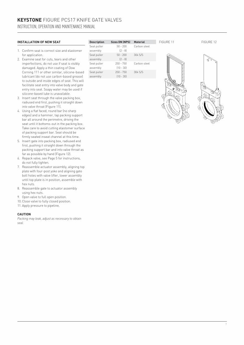
INSTALLATION OF NEW SEAT
1. Confirm seat is correct size and elastomer for application.
2. Examine seat for cuts, tears and other imperfections, do not use if seat is visibly damaged. Apply a thin coating of Dow Corning 111 or other similar, silicone-based lubricant (do not use carbon-based grease) to outside and inside edges of seat. This will facilitate seat entry into valve body and gate entry into seat. Soapy water may be used if silicone-based lube is unavailable.
3. Insert seat through the valve packing box, radiused end first, pushing it straight down into valve throat (Figure 11).
4. Using a flat faced, round bar (no sharp edges) and a hammer, tap packing support bar all around the perimetre, driving the seat until it bottoms-out in the packing box. Take care to avoid cutting elastomer surface of packing support bar. Seat should be firmly seated inseat channel at this time.
5. Insert gate into packing box, radiused end first, pushing it straight down through the packing support bar and into valve throat as far as possible by hand (Figure 12).
6. Repack valve, see Page 5 for instructions, do not fully tighten.
7. Reassemble actuator assembly, aligning top plate with four-post yoke and aligning gate bolt holes with valve lifter, lower assembly until top plate is in position, assemble with hex nuts.
8. Reassemble gate to actuator assembly using hex nuts.
9. Open valve to full open position.10. Close valve to fully closed position.11. Apply pressure to pipeline,
Description Sizes DN (NPS) MaterialSeat puller assembly
50 - 200(2 - 8)
Carbon steel
Seat puller assembly
50 - 200(2 - 8)
304 S/S
Seat puller assembly
250 - 750(10 - 30)
Carbon steel
Seat puller assembly
250 - 750(10 - 30)
304 S/S
CAUTIONPacking may leak, adjust as necessary to obtain seal.
FIGURE 11 FIGURE 12
KEYSTONE FIGURE PCS17 KNIFE GATE VALVESINSTRUCTION, OPERATION AND MAINTENANCE MANUAL

8
SPINDLE NUT REPLACEMENT INSTRUCTIONS
It is not necessary, or desired, to remove the yoke assembly to replace the nut.
Tools required1. Pipe wrench or large crescent wrench2. Appropriate size open end wrench for
retainer bolts
CAUTIONFollow required safety procedure and policies. Use proper lifting and support techniques when moving valve and or valve subassemblies.
Prepare the valve1. Line should be depressurized or gate
secured prior to disassembly. If valve is equipped with pin-style lockouts (see Figure 16, page 10) gate can be locked in the open or closed position using the lock pin. If pin-style lockouts are not present, the gate must be held in place to prevent unwanted movement. These preCautions are necessary to keep the gate from moving
KEYSTONE FIGURE PCS17 KNIFE GATE VALVESINSTRUCTION, OPERATION AND MAINTENANCE MANUAL
Disassembly1. It is not necessary or desired to remove or
loosen the stop nut during disassembly.Removing or loosening the stop nut will compromise the seat/stroke adjustment.
2. Using pipe or crescent wrench, remove handwheel retaining nut from spindle nut.
3. Remove handwheel.4. Remove (2) or (4) retainer bolts.5. Pull retainer off.6. Rotate old spindle nut until free from
spindle.
CYLINDER SUPPORT METHODS FOR HORIZONTALLY OR OFF-VERTICAL MOUNTING
Cylinders require additional support when mounted in the other than vertical position. Failure to do so could lead to premature failure of cylinder and/or valve. The following illustrations are suggestions, specific details will have to be determined by customer so support best suits surrounding area. It is important that the cylinder/gate alignment be maintained during valve operation. Supports should be designed to maintain alignment and support bulk of cylinder weight.
Reassembly1. Apply standard bearing grease onto to
exposed spindle thread. (Use material which meets ASTM 4950 GBLB).
2. Rotate new spindle nut onto spindle until it bottoms against top plate.
3. Place retainer over spindle nut, lining up the bolt holes.
4. Replace retainer bolts and nuts, tighten completely.
5. Place handwheel over spindle nut, aligning the hex.
6. Attach new handwheel retainer nut, using pipe wrench or crescent wrench, tighten completely.
7. Grease as required using grease fitting.
CAUTIONTie-rod mounted supports are not recommended on spring-style cylinder actuators.
Stop nut
Spindle assembly
Retaining nut
Handwheel
Spindle nut
Retainer
Retainer bolt
FIGURE 13
Installation A
Appropriate tie-in capable of supporting load.
Turnbuckle for adjustment
Saddle style hanger
Installation B
Appropriate tie-in capable of supporting load.
Saddle style support
Installation C
Appropriate tie-in capable of supporting load.
Turnbuckle for adjustment
Alternate head-support, saddle style preferred

9
KEYSTONE FIGURE PCS17 KNIFE GATE VALVESINSTRUCTION, OPERATION AND MAINTENANCE MANUAL
RETRO FITTING BEVEL GEAR OPERATORS
Conversion kits include bevel gear operator with integral thrust style spindle nut, conversion mounting plate, appropriate bolts, and handwheel or drive nut as required. Existing spindle and yoke posts will be reused. If spindle or yoke posts require replacement, contact the factory.
CAUTIONFollow required safety procedure and policies. Assure line is not pressurized or gate has been secured to prevent unwanted movement before disassembly. Use proper lifting and support techniques when moving valve and or valve subassemblies.
Tools required1. Pipe wrench or large crescent wrench2. Appropriate size open end wrenches or
sockets
Prepare the valve1. Line should be depressurized or gate
secured prior to disassembly. If valve is equipped with pin-style lockouts (Figure 16, page 10) gate can be locked in the open or closed position using the lock pin. If pin-style lockouts are not present, the gate must be held in place to prevent unwanted movement.These preCautions are necessary to keep the gate from moving.
Reassembly1. The conversion kit will be shipped with the
thrust spindle nut installed in the bevel gear.
2. Place the adapter plate over the 4-Post yoke legs aligning the holes. (Figure 14)
3. Attach nuts onto 4-post yoke legs securing the top plate into position.
4. Apply standard bearing grease onto to exposed spindle thread. (Use material which meets ASTM 4950 GBLB).
5. Slip the bevel gear over the spindle nut, engaging the threads. Rotate the handwheel which will in turn rotate the thrust spindle nut down the spindle, bringing the bevel gear into proper position, aligning the bolt holes.
6. Bolt the bevel gear to the adapter plate. Do not overstress bolting.
7. Stroke the valve from full open to full closed making sure all parts are aligned and working properly. Check bolts for tightness, the gate and operator assembly should stay snug with the valve body.
8. If binding or off-center movement of gate is evident, loosen yoke bolts, stroke gate up and down a few times, retighten yoke bolts.
Disassembly1. Using pipe or crescent wrench, remove
handwheel retaining nut from spindle nut.2. Remove handwheel.3. Remove (2) or (4) retainer bolts.4. Pull retainer off5. Rotate old spindle nut until free from
spindle.6. Remove nuts from the 4-post yoke legs.7. Pull existing top plate up and away from
valve.
FIGURE 14
FIGURE 15
Bevel gear actuator
Thrust-style spindle nut included
Mount plate
Mount bolts
4-Post Yoke Leg
Spindle

10
OPTIONAL LOCKOUTS
Valve is not suitable for man-safe conditions due to potential for downstream leakage, even in the closed and locked position. Lockouts (if provided) are designed to prevent unauthorized operation of the valve. They are not designed to guarantee normal valve performance if unauthorized operation is attempted. The fit of the pin may allow the gate to move up to 1.5 mm (9/16") from the closed position. Unauthorized operation may result in increased valve leakage, damage to the operator assembly and the packing may be compromised. Valve may require repair prior to putting back in service.Lockouts are designed to resist the normal manual operating thrust. In order to assure complete lockout compliance, any automatic valve actuator must be placed in a ZERO ENERGY STATE by isolating all potential energy sources including electricity, operator supply air or hydraulic fluids.
CAUTIONValves supplied spring cylinders with the spring compressed where the mechanical energy cannot be placed in a ZERO ENERGY STATE. Take extreme care when inserting and removing the lockout pin. If the valve is actuated or the opposing pneumatic force is removed during the insertion process injury may occur.
NOTESee Figure 16, for available lockout assemblies, not all lockout options are available on all valves.
The following are the factory’s recommendations for storage procedures to retain maximum product integrity during long term storage of 1 to 5 years.
The shelf life listed is a guideline and is not a substitute for examination of cured material at the time of intended use.To maintain shelf life, spare seats should be stored in accordance with the following.1. Store at ambient temperature up to 30°C
(86°F), with 60 - 90% relative humidity away from direct sunlight and at a minimum distance of 4.6 meters (15 feet) away from electric motors is mandatory.
2. Care must be taken to avoid storage in a stressed condition such as piled too high or on a plain pallet overhanging a sharp edge.
3. First in - first out inventory control should be practiced.
4. The above elastomer shelf life guidelines are for components that are not already installed in a valve.
KEYSTONE FIGURE PCS17 KNIFE GATE VALVESINSTRUCTION, OPERATION AND MAINTENANCE MANUAL
L1: Pin style, both open and closed lock positions, pin not included
L2: Pin style, open position only, pin not included
L3: Pin style, closed position only, pin not included
L4: Carbon steel bevel gear handwheel lockout, does not require pin.
L5: Stainless steel bevel gear handwheel lockout, does not require pin.
L6: Case hardened pin for use on L1, L2 or L3. Order as L1L6, L2L6, or L3L6.
L7: Cable handwheel lockout for handwheel valves only, not available on DN 750 (NPS 30).
FIGURE 16
open closed
open
closed
pin

11
KEYSTONE FIGURE PCS17 KNIFE GATE VALVESINSTRUCTION, OPERATION AND MAINTENANCE MANUAL
HANDWHEEL OR BEVEL GEAR OPERATED VALVES
A. Equipment orientation: Valves may be stored in the vertical or horizontal position.
B. Preparation for storage: Valves may be stored as shipped, provided the above storage facility and equipment orientation instructions above are followed. If valve packaging is altered or removed for receiving inspection, repackage valve as originally received.
C. Storage inspection: Visual inspection shall be performed on a semiannual basis and results recorded. Inspection as a minimum shall include reviewing the following:
Packaging Flange covers Dryness CleanlinessD. Maintenance: Maintenance shall consist
of correcting deficiencies noted during inspection. All maintenance shall be recorded. Contact factory prior to performing any maintenance if valve is still covered under warranty.
CYLINDER OPERATED VALVES
A. Equipment orientation: The preferred orientation for optimum protection is with the valve fully opened and the cylinder in the vertical position. This position gives the best support to the cylinder rod and helps reduces the chance of a “flat spot” developing on the cylinder seals. An acceptable alternate position for valves with cylinder diameters of less than 150 mm (6") is with the cylinder in the horizontal position.
B. Preparation for storage: Valves may be stored as shipped, provided the above storage facility and equipment orientation instructions above are followed. If valve packaging is altered or removed for receiving inspection, repackage valve as originally received.
C. Cylinder storage: These cylinder storage instructions are not intended to replace the instructions of the specific cylinder manufacturer and are to be used as a guide only. If specific instructions are required, please contact our office. For storage of up to 3 years; Squirt a high quality grade of hydraulic oil or synthetic lubricant into the cylinder ports and operate cylinder 6-12 times on a yearly basis. For storage 3-5 years; Lubricate as above. Additionally, extend cylinder rod until the valve is fully closed. Coat cylinder rod with high quality heavy grease or synthetic lubricant. Retract cylinder rod until valve is fully open, drawing lubricant into rod end of cylinder. Securely plug cylinder ports with pipe plugs, if cylinder is not prepiped to control accessories. If cylinder is prepiped to accessories, plug all input and output ports of accessories.
D. Storage inspection: Visual inspection shall be performed on a semiannual basis and results recorded. Inspection as a minimum shall include reviewing the following:
- Packaging - Flange covers - Dryness - CleanlinessE. Maintenance: Maintenance shall consist
of correcting deficiencies noted during inspection. All maintenance shall be recorded. Contact factory prior to performing any maintenance if valve is still covered under warranty.

Neither Emerson, Emerson Automation Solutions, nor any of their affiliated entities assumes responsibility for the selection, use or maintenance of any product. Responsibility for proper selection, use, and maintenance of any product remains solely with the purchaser and end user.
Keystone is a mark owned by one of the companies in the Emerson Automation Solutions business unit of Emerson Electric Co. Emerson Automation Solutions, Emerson and the Emerson logo are trademarks and service marks of Emerson Electric Co. All other marks are the property of their respective owners.
The contents of this publication are presented for informational purposes only, and while every effort has been made to ensure their accuracy, they are not to be construed as warranties or guarantees, express or implied, regarding the products or services described herein or their use or applicability. All sales are governed by our terms and conditions, which are available upon request. We reserve the right to modify or improve the designs or specifications of such products at any time without notice.
Emerson.com/FinalControl