
Keysight Technologie’s Conduct DVB-T/H Conformance...
19
Keysight Technologie’s Conduct DVB-T/H Conformance Tests with Keysight’s Real-Time DVB-T/H Digital Video Solution Application Note
Transcript of Keysight Technologie’s Conduct DVB-T/H Conformance...
Keysight Technologie’s Conduct DVB-T/H Conformance Tests with Keysight’s Real-Time DVB-T/H Digital Video Solution
Application Note

Introduction
DVB-T is the most widely used digital television standard for terrestrial television transmissions. DVB-H is an
extension of DVB-T, which is optimized for mobile television transmissions. They use OFDM technology and a
range of specifications including:
– 3 modulation options (QPSK, 16QAM, 64QAM): There is a balance between the rate at which data can be
transmitted and the signal to noise ratio that can be tolerated
– Different FEC rates: Error correction uses convolutional coding and Reed Solomon coding with code rates
of 1/2, 2/3, 3/4, 5/6, or 7/8, depending upon the requirements
– 2k, 4k, or 8k carriers with four guard interval options: 1/4, 1/8, 1/16, 1/32 to provide broadcasters with
network planning flexibility
– 5, 6, 7, or 8 MHz channel bandwidths for variable available bandwidth and channel separation
Keysight Technologies, Inc. provides real-time and arbitrary DVB-T/H signal sources which fully support all of
these features. Conformance test for DVB-T/H receivers can be conducted using the N5106A PXB, N7623B Signal
Studio for digital video, and N5182A MXG.
This application note provides an introduction to the performance test requirements for DVB-T/H receivers, as
defined in EICTA MBRAI 2.0, and describes test setup and configurations for N5106A PXB, N5182A MXG, and
N7623B Signal Studio for digital video.

3
Introduction . . . . . . . . . . . . . . . . . . . . . . . . . . . . . . . . . . . . . . . . . . . . . . . . . . . . . . . 2
Overview of Requirements for Receiver Performance . . . . . . . . . . . . . . . . . . . . . . 4
PXB and N7623B in Brief . . . . . . . . . . . . . . . . . . . . . . . . . . . . . . . . . . . . . . . . . . . . . 4
Test Setup and Configuration . . . . . . . . . . . . . . . . . . . . . . . . . . . . . . . . . . . . . . . . . . 5
C/N performance . . . . . . . . . . . . . . . . . . . . . . . . . . . . . . . . . . . . . . . . . . . . . . . . 6
Receiver minimum and maximum input signal levels . . . . . . . . . . . . . . . . . . 10
Immunity to interference . . . . . . . . . . . . . . . . . . . . . . . . . . . . . . . . . . . . . . . . . 11
Guard interval utilization . . . . . . . . . . . . . . . . . . . . . . . . . . . . . . . . . . . . . . . . . 13
Tolerance to impulse interference . . . . . . . . . . . . . . . . . . . . . . . . . . . . . . . . . . 14
GSM900 TX signal blocking test . . . . . . . . . . . . . . . . . . . . . . . . . . . . . . . . . . . 16
Mobile SFN channel test . . . . . . . . . . . . . . . . . . . . . . . . . . . . . . . . . . . . . . . . . 17
Conclusions . . . . . . . . . . . . . . . . . . . . . . . . . . . . . . . . . . . . . . . . . . . . . . . . . . . . . . . 18
Reference. . . . . . . . . . . . . . . . . . . . . . . . . . . . . . . . . . . . . . . . . . . . . . . . . . . . . . . . . 18
Related Literature . . . . . . . . . . . . . . . . . . . . . . . . . . . . . . . . . . . . . . . . . . . . . . . . . . 18
Table of Contents
4
Overview of Requirements for Receiver Performance
EICTA MBRAI 2.0[2][3] includes system
information as well as specifications
for minimum RF performance. The
defined conformance measurements
include:
– C/N performance, including
Gaussian, indoor, outdoor, and
mobile environments
– Receiver minimum and maximum
input signal levels
– Immunity to analog and/or digi-
tal signals in other channels
– Immunity to co-channel interfer-
ence from analog TV signals
– Guard interval utilization: echoes
within guard interval
– Guard interval utilization: echoes
outside the guard interval
– Tolerance to impulse interfer-
ence
– GSM900 TX signal blocking test
– Mobile SFN channel test
Four different degradation criteria
are used in MBRAI 2.0 Part 2[3]
a) Reference BER, defined as BER =
2 x 10⁻⁴ after Viterbi decoding
b) Picture failure point (PFP), defined
as the C/N when picture errors
become visible. This is preferred
when BER measurements are
unstable or unavailable.
c) Subjective failure point (SFP) in
mobile reception
d) DVB-H error criterion: MPE-FEC
frame error rate (MFER)
Some receivers can provide reference
BER and some cannot, in which case
b and c are used.
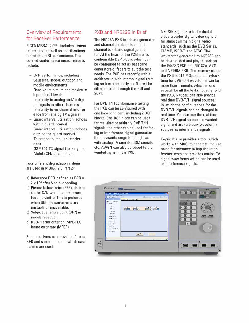
PXB and N7623B in Brief
The N5106A PXB baseband generator
and channel emulator is a multi-
channel baseband signal genera-
tor. At the heart of the PXB are its
configurable DSP blocks which can
be configured to act as baseband
generators or faders to suit the test
needs. The PXB has reconfigurable
architecture with internal signal rout-
ing so it can be easily configured for
different tests through the GUI and
SCPI.
For DVB-T/H conformance testing,
the PXB can be configured with
one baseband card, including 2 DSP
blocks. One DSP block can be used
for real-time or arbitrary DVB-T/H
signals; the other can be used for fad-
ing or interference signal generation
if the dynamic range is enough, as
with analog TV signals, GSM signals,
etc. AWGN can also be added to the
wanted signal in the PXB.
N7623B Signal Studio for digital
video provides digital video signals
for almost all main digital video
standards, such as the DVB Series,
CMMB, ISDB-T, and ATSC. The
waveforms generated by N7623B can
be downloaded and played back on
the E4438C ESG, the N5182A MXG,
and N5106A PXB. The memory size of
the PXB is 512 MSa, so the playback
time for DVB-T/H waveforms can be
more than 1 minute, which is long
enough for all the tests. Together with
the PXB, N7623B can also provide
real time DVB-T/H signal sources,
in which the configurations for the
DVB-T/H signals can be changed in
real time. You can use the real time
DVB-T/H signal sources as wanted
signal and arb (arbitrary waveform)
sources as interference signals.
Keysight also provides a tool, which
works with MXG, to generate impulse
noise for tolerance to impulse inter-
ference tests and provides analog TV
signal waveforms which can be used
as interference signals.

5
Test Setup and Coniguration
Conformance testing requires wanted signals as well as impairments, such as interference signal, fading, and AWGN.
The wanted DVB-T/H signal is generated by the N5106A PXB and then up-converted to RF frequency through the MXG.
Figure 1 shows the test system for C/N performance testing, receiver minimum and maximum input signal levels testing,
guard interval utilization testing, and mobile SFN channel testing. Fading and AWGN can be added to the wanted signal in
the N5106A PXB.
Figure 1. Conformance test system 1
N5182A MXGDVB-T/H receiver
under test
LAN (or GPIB)LVDS
N5106A PXB
MBRAI conformance measurements supported by the above test systems are listed in the table below.
Measurements Test system
C/N performance Conformance test system 1
Receiver minimum and maximum input signal levels Conformance test system 1
Immunity to interference test Conformance test system 2
Guard interval utilizations Conformance test system 1
Tolerance to impulse interference Conformance test system 2
GSM900 TX signal blocking test Conformance test system 2
Mobile SFN channel test Conformance test system 1
Table 1. Test system for each measurement
N5182A MXG
N5182A MXG
N5182A MXG����
�����
����
Interference 1
Wanted signal
DVB-T/H receiver under test
LAN (or GPIB)LVDS
N5106A PXB
1
2
3
Figure 2. Conformance test system 2
Figure 2 shows the test system for immunity to interference testing, tolerance to impulse interference testing, and
GSM900 TX signal blocking testing. The wanted signal and the interference signals are combined at RF level. Only for
immunity to interference testing, with patterns L1, L2, and L4 is the third MXG needed.

6
The configurations for each model are listed in the following table.
Model number Options Description
N5106A PXB – Option 186 612 2 DSP blocks on 1 baseband card
632 2 I/O ports - 2 analog I/Q out and 2 digital I/O on 1 I/O card
EFP Baseband generation
JFP Calibrated AWGN
QFP Fading with SISO channel models
1 N5182A MXG 503 Frequency range from 250 kHz to 3 GHz
2 N5182A MXG (as interference 1) 503 503 Frequency range from 250 kHz to 3 GHz
652 or 654 Internal baseband generator
UNT AM, FM, phase modulation
403 Calibrated AWGN
099 Expanded license key upgradeability
1EA High output power with electronic attenuator (requires Option 099)
3 N5182A MXG (as interference 2 for
analog interference)
503
651, 652, or 654
Frequency range from 250 kHz to 3 GHz
Internal baseband generator
N7623B Signal Studio for digital video 6FP Connect to N5106A PXB
3FP Connect to N5182A MXG (interference 1)
QFP Advanced DVB-T/H (interference 1)
EFP Advanced real-time DVB-T/H (in PXB)
Table 2. Configurations for each model
Test Setup and Coniguration, Continued
C/N performance
C/N performance testing is con-
ducted to measure the receiver’s
performance with the presence of
fading and noise. C/N performance in
Gaussian channel, portable channel,
portable indoor (PI), portable outdoor
(PO), and mobile channels are defined
in the specifications.
Using test system 1, set the output
of the MXG to make sure the power
of the DVB-T/H signal is -50 dBm (at
the receiver point) and the frequency
is 666 MHz. DVB-T/H signals with
QPSK, 16-QAM, 64 QAM and code
rates of 1/2, 2/3, and 3/4 are needed.
C/N performance in Gaussian channel
The PXB can add AWGN signals to
the wanted signal to simulate the
Gaussian channel.
The following section first introduces
the settings in the PXB, and then
describes the measurement procedure.

7
PXB settings
1. Configure the PXB as shown in
Figure 3. One DSP is used as the
baseband generator to generate
real time DVB-T/H signals.
2. Configure the basic DVB-T/H
settings (for example), as shown
in Figure 4, and load the payloads
needed as shown in Figure 5. The
TS file can be stored on the hard
disk of the PXB.
3. Turn on AWGN and set the
bandwidth of the Gaussian signals
and C/N as shown in Figure 6.
The Signal to Noise Ratio on the
interface corresponds to the C/N
defined in the specifications.
Measurement procedure
Decrease the C/N by changing the
signal-to-noise ratio value in Figure 6
until the degradation criteria is met.
If this C/N is lower than that defined
in the specifications, it means the
receiver passes this test. Repeat the
measurements to cover all the cases
defined in the specifications[2][3].
Figure 3. PXB configured as 1 channel
Figure 4. Basic DVB-T/H settings
Figure 5. Payload settings
Figure 6. AWGN settings in the PXB

8
C/N performance in fading channels
Fading channels include the
portable channel, the PI/PO
channel, and the mobile channel.
This section first introduces the
settings in the PXB, and then
describes the measurement
procedures.
PXB Settings
1. Configure the PXB as shown in
Figure 7. Here, two DSP blocks are
used, one DSP block to generate
the baseband signal, and the other
to simulate multi-path fading.
2. Set up the parameters for real-
time DVB-T/H signals and load
the payloads as shown in the
example in Figure 8.
3. Choose the fading profiles to be
used by exploring the channel
models under Fader 1 Channel
Model, DVB on the interface (see
Figure 9). All the fading profiles
defined in MBRAI 2.0 Part 1 have
been preset in the N5106A PXB as
shown in Figure 9, allowing users
the convenience of selecting them
directly instead of manually set-
ting them up.
Figure 7. PXB configuration for multipath fading testing
Figure 8. DVB-T/H basic setting
Figure 9. Preset channel profiles

9
Note that for mobile channel profiles,
you need to adjust the Doppler
frequency as defined in the specifica-
tions under Fader 1 Paths, as shown
in Figure 10. Figure 10 is an example
of the predefined TU 6 channel profile
under mobile reception.
4. Set up the C/N as shown in Figure 11.
Measurement procedure for the portable and PI/PO channels
Decrease the C/N by changing the
signal-to-noise ratio value in Figure
11 until the degradation criteria is
met. If this C/N is lower than that
defined in the specifications, it means
the receiver passes the test. Repeat
the measurement to cover all the
cases defined in the specifications[3].
Figure 10. Doppler frequency settings in mobile channels
Figure 11. C/N settings
Measurement procedure for the mobile channel
1. Set the Doppler frequency to 10 Hz as shown in Figure 10, then decrease
the C/N by changing the signal-to-noise ratio value in Figure 11 until the
degradation criteria is met. Record this C/N as “C/Nmin
,“ which is for the
TP4 point in MBRAI Part1.
2. Set the C/N to (specified C/Nmin
+ 3 dB), increase the Doppler frequency
until the degradation criteria is met. Record this Doppler frequency as
“Fd3dB
.”
3. Turn off the AWGN as shown in Figure 6, increase the Doppler frequency
until the degradation criteria is met. Record this Doppler frequency as
“Fdmax
.” Note that all C/Nmin
, Fd3dB
, and Fdmax
need to meet the requirements
in the specifications.
4. Repeat the measurement to cover all the cases defined in the
specifications[3].

10
Receiver minimum and maximum input signal levels
The purpose of the receiver minimum
and maximum input signal levels test
is to measure the operational power
range of DVB-T/H receiver under test.
Refer back to Figure 1 to see this
test system. The DVB-T/H signal to
be tested is QPSK with a code rate
of 1/2. The following section first
introduces the settings in the PXB,
and then describes the measurement
procedures.
PXB settings
1. Configure the PXB as shown in
Figure 12. One DSP is used as a
baseband generator to generate
real time DVB-T/H signals.
2. Set up the basic DVB-T/H settings
and load the payloads as shown in
the example in Figure 13.
Figure 12. PXB configured as 1 channel
Figure 13. Basic DVB-T/H settings
Measurement procedure
In this test, the loss of the cable (X dB) connecting the MXG and the DVB-T/H
receiver needs to be taken into consideration. The measurement procedure is as
follows:
1. Decrease the power level of the MXG output until the receiver meets the
degradation criteria. Record the power level as “Min.” The minimum input
level is (Min-X) dB, which needs to be lower than that defined in section 6.2,
MBRAI 2.0 Part 2[3].
2. Increase the power level to the defined maximum power level plus X dB. If
the signal’s quality is above the degradation criteria, it means the receiver
passes this test.
3. Repeat the measurement to cover all the frequencies defined in the
specifications[3].

11
Immunity to interference
The immunity to interference test is
conducted in order to ensure consis-
tent receiver quality in the presence
of strong interference neighboring the
wanted signal channel.
The test system configuration in
the immunity to interference test is
shown in Figure 2. The interference
signals are generated in one or two
MXGs using their respective arbitrary
waveform generators, together with
the N7623B QFP advanced DVB-T/H
option.
In MBRAI, immunities to S1, S2,
L1, L2, L3, and L4 patterns and
co-channel interference from analog
TV signals are defined. Below, the
patterns are described in two
categories.
Category 1: Immunity to patterns
S1, S2, L3, and co-channel interfer-
ence from analog TV signals, where
one MXG is used to generate interfer-
ence signals.
– Pattern S1: Analog interference
signal on N+1 or N+2 at channel
45 (666 MHz) in UHF and chan-
nel 8 (199 MHz) in VHF.
– Pattern S2: Interference DVB-
T/H signal on N+1 or N+2 at
channel 45 in UHF and channel
8 in VHF.
– Pattern L3: One DVB-T/H
interference signal on N+4 and
another DVB-T/H interference
signal on N+2 at channels 21, 45
and 64 in UHF and channel 8 in
VHF. Use
the multi-carrier function of
N7623B QFP to generate these
two interference signals in one
waveform.
– Co-channel analog interference
at channel 45 in UHF.
Category 2: Immunity to patterns L1,
L2, and L4, where two MXGs are used
to generate interference signals.
– Pattern L1: One analog interfer-
ence signal on N+4 and one
DVB-T/H interference signal on
N+2 at channels 21 (474 MHz),
45 and 64 (818 MHz) in UHF and
channel 8 in VHF.
– Pattern L2: One analog interfer-
ence signal on N+4 and another
analog interference signal on
N+2 at channels 21, 45 and 64 in
UHF and channel 8 in VHF.
– Pattern L4: One analog interfer-
ence signal at channel 5 (177.5
MHz) and one DVB-T/H interfer-
ence signal at channel 21, while
the wanted signal is at channel
43 (650 MHz).
b dBa dB
AnalogDVB-T/H
N + 4N + 3N + 2N + 1N
Wanted
DVB-T/H
Figure 14. Immunity pattern (pattern L1 is shown as an example)
The wanted and interference DVB-
T/H signals, as well as the analog
signals in the test are outlined in the
following example:
– Wanted real-time DVB-T/H
signals: 2k mode, 16 QAM, 1/2
code rate, and 1/8 guard interval
(generated by N7623B-EFP)
– Interference DVB-T/H signals:
2k mode, 16 QAM, 1/2 code rate,
and 1/8 guard interval (gener-
ated by N7623B-QFP)
– Analog signals: PAL-D. Keysight
provides PAL-D waveforms
which can be loaded directly into
the MXG.
The following section first intro-
duces the settings in the PXB and
the N7623B, and then describes the
measurement procedure.
12
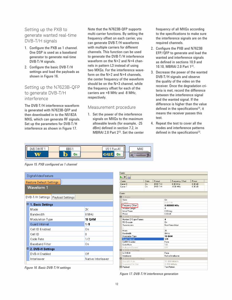
Setting up the PXB to generate wanted real-time DVB-T/H signals
1. Configure the PXB as 1 channel.
One DSP is used as a baseband
generator to generate real-time
DVB-T/H signals.
2. Configure the basic DVB-T/H
settings and load the payloads as
shown in Figure 16.
Setting up the N7623B-QFP to generate DVB-T/H interference
The DVB-T/H interference waveform
is generated with N7623B-QFP and
then downloaded in to the N5182A
MXG, which can generate RF signals.
Set up the parameters for DVB-T/H
interference as shown in Figure 17.
Figure 15. PXB configured as 1 channel
Figure 16. Basic DVB-T/H settings
Figure 17. DVB-T/H interference generation
Note that the N7623B-QFP supports
multi-carrier functions. By setting the
frequency offset on each carrier, you
can generate DVB-T/H waveforms
with multiple carriers for different
channels. This function can be used
to generate the DVB-T/H interference
waveform on the N+2 and N+4 chan-
nels in pattern L3 instead of using
two MXGs. For the interference wave-
form on the N+2 and N+4 channels,
the center frequency of the waveform
should be on the N+3 channel, while
the frequency offset for each of the
carriers are +8 MHz and -8 MHz,
respectively.
Measurement procedure
1. Set the power of the interference
signals on MXGs to the maximum
allowable levels (for example, -25
dBm) defined in section 7.2, in
MBRAI 2.0 Part 2[3]. Set the center
frequency of all MXGs according
to the specifications to make sure
the interference signals are on the
required channels.
2. Configure the PXB and N7623B
EFP/QFP to generate and load the
wanted and interference signals
as defined in sections 10.9 and
10.10, MBRAI 2.0 Part 1[2].
3. Decrease the power of the wanted
DVB-T/H signals and observe
the quality of the video on the
receiver. Once the degradation cri-
teria is met, record the difference
between the interference signal
and the wanted signal. If the
difference is higher than the value
defined in the specifications[3], it
means the receiver passes this
test.
4. Repeat the test to cover all the
modes and interference patterns
defined in the specifications[3].

13
Guard interval utilization
The guard interval utilization test is
conducted to measure the perfor-
mance of the DVB-T/H receiver in the
presence of echoes. The test system
is shown in Figure 1. Set the output
of the MXG to make sure the power
level of the DVB-T/H signal is
-40 dBm (at the receiver point) and
the frequency is 666 MHz.
The following section first introduces
the settings in the PXB, and then
describes the measurement procedure.
PXB settings
1. Configure the PXB as shown in
Figure 18. Here, two DSP blocks
are used, one to generate the
baseband signal, and the other to
simulate multi-path fading.
2. Set up the parameters for real-
time DVB-T/H signals and load
the payloads as shown in the
example in Figure 19.
3. Set up the echoes as defined in
the specifications under Fader 1
Paths as shown on the screen in
Figure 20, below. Take the DVB-
T/H signal with the 8K mode and
GI of 1/4 for example, while Tg is
224 µs and 0.9 x Tg = 201.6 µs.
4. Set up the C/N as shown in
Figure 21. The signal-to-noise
ratio corresponds to the C/N in
the specifications.
Measurement procedure
Set up the echoes and C/N as
defined in the specifications, and
check whether the reception quality
is better than the degradation criteria.
If it is better, it means that the
receiver passes the test. Repeat the
measurement to cover all the cases
defined in the specifications[3].
Figure 18. PXB configuration for multipath fading test
Figure 19. DVB-T/H basic settings
Figure 20. Echo setup
Figure 21. C/N settings

14
Tolerance to impulse interference
The tolerance to impulse interference
test is conducted to measure the
performance of the DVB-T/H receiver
in the presence of impulsive noise. In
this test, both wanted DVB-T/H sig-
nals and impulsive noise are needed.
The connection to the instrument
is shown in Figure 2. A real-time
DVB-T/H signal is generated in
the PXB and up-converted to RF
frequency by an MXG. Impulsive
noise is generated in another MXG
using the Keysight impulsive noise
generator tool.
The following section first intro-
duces the settings in the PXB
and the impulsive noise generator,
and then describes the measure-
ment procedure.
PXB settings
Set up the PXB with N7623B
Option EFP to generate the wanted
real-time DVB-T/H signal as follows:
1. Configure the PXB as 1 channel.
2. Set up the basic DVB-T/H set-
tings and load the payloads as
shown in Figure 23.
Setting up the impulsive noise generation tool
To comply with the measurement
requirements in the MBRAI, Keysight
provides a software tool to generate
the impulse noise interferences.
Use the software together with a
signal generator (ESG or MXG) with
Option 403 (calibrated AWGN).
The software generates waveforms
according to the test patterns, as
defined in the specifications, to
control the markers in the signal
generator, route these markers to
RF blanking, and at the same time
turn on the real-time AWGN in ARB
mode. By routing the markers to
RF blanking, the signal generator
blanks the RF output according to
the markers. Then the output of the
signal generator is the real-time
impulse noise.
Figure 22. PXB configured as 1 channel
Figure 23. Basic DVB-T/H settings
Figure 24. Impulsive noise generation tool

15
The six patterns defined in MBRAI
are pre-defined in the impulsive noise
generation tool. You can select them
directly or set the pattern manually.
Figure 25 shows the generated
impulsive noise, which is test pattern
6. It is viewed with an oscilloscope.
The left graph represents a complete
burst containing 40 pulses. The spac-
ing between each pulse is random,
between 0.5 ~ 1 µs. The right graph
shows a larger view of the three
pulses, circled in red. The signal in
each pulse is real-time AWGN with
the length of 250 ns. In the space
between two pulses, the signal gen-
erator switches off the RF output, so
the signal displayed is the noise floor
of the oscilloscope.
Measurement procedure
1. Set the center frequency of both signal generators to 666 MHz, set
the amplitude of the MXG for impulse noise generation to -35 dBm
(at the receiver point) and the MXG for DVB-T/H signals to -30 dBm
(at the receiver point).
2. Configure the PXB and the impulsive noise generator properly to
generate the DVB-T/H and impulsive noise signal.
3. Decrease the amplitude of the signal generator for DVB-T/H until
the degradation criteria is met. Record the power difference (I/C)
between the impulse noise and DVB-T/H signal. If the power differ-
ence is higher than that defined in the specifications, it means the
receiver passes the test.
4. Repeat the measurement to cover all the test cases defined in
the specifications[3].
Figure 25. A view of the impulse noise

16
GSM900 TX signal blocking test
The GSM900 TX signal blocking test
is conducted in order to verify that
the sensitivity of DVB-H receiver does
not degrade too heavily while the
GSM900 TX blocking signal is present
in the receiver input.
The test system is shown in Figure 2.
The PXB is connected to one MXG to
generate the wanted real time DVB-H
signal. A different MXG is used to
generate the GSM900 TX signal.
The DVB-H signal under test is: 8K
OFDM, GI=1/4, QPSK, CR = 1/2,
MPE-FEC CR = 3/4. Note that the
MPE-FEC CR is set in the DVB-H
video stream loaded in the PXB.
Setting up the MXG to gen-erate a GSM900 TX signal
The GSM900 TX signal is simulated
with a 1 KHz CW signal, which is FM
modulated with ±50 kHz deviation.
The frequency of the signal is 880
MHz. The MXG is set to transmit this
signal as shown in Figure 26. The
output power is 20 dBm, assuming
the attenuation of the cable and
connections between the MXG and
the DVB-H receiver is 2 dB.
Figure 26. MXG settings
Figure 27. Configure the PXB as 1 channel
Figure 28. Basic DVB-H settings
Setting up the PXB to gen-erate the DVB-H signal
1. Configure the PXB as shown in
Figure 27. Note that you need
to choose Real Time as the
Waveform Type and DVB-T/H as
the Waveform Format under User
File to generate real-time DVB-
T/H signals.
2. Configure the basic DVB-T/H
settings and load the payloads as
shown in Figure 28.
3. Decrease the power of the DVB-
T/H signal through the PXB or on
the MXG directly. If the degrada-
tion criteria is reached, record
the current value of the DVB-T/H
signal. This value should be lower
than or equal to the ones defined
in the specifications[3].

17
Mobile SFN channel test
The mobile SFN channel test is
conducted in order to verify that the
DVB-H receiver can work properly in
the mobile SFN environment. The test
system for the mobile SFN channel
test is shown in Figure 1.
The DVB-H signal under test is: 8K
OFDM, GI = 1/4, CR = 1/2, MPE-FEC
CR = 3/4. The measurement fre-
quency is channel 45 (666 MHz).
The following section first introduces
the settings in the PXB, and then
describes the measurement procedure.
PXB settings
1. Configure the PXB as shown in
Figure 29. Here, two DSP blocks
are used, one to generate the
baseband signal, and one to
simulate echoes.
2. Configure the basic DVB-H
settings and load the payloads.
3. Set the channel profiles as defined
in the specifications in the Fader1
Paths screen shown, in Figure 31.
Take weak long echo for example.
4. Configure the C/N as shown in
Figure 32.
Measurement procedure
1. Set the Doppler frequency to
10 Hz as shown in Figure 31, then
decrease the C/N by changing
the signal-to-noise ratio value in
Figure 32 until the degradation
criteria is reached. Record this
C/N as “C/Nmin
.”
2. Set the C/N to (specified C/Nmin
+ 3 dB), increase the Doppler
frequency until the degradation
criteria is reached. Record this
Doppler frequency as “Fd3dB
.”
Note that C/Nmin
and Fd3dB
should
meet the requirements in the
specifications.
3. Repeat the measurement to
cover all the cases defined in
the specifications[3].
Figure 29. PXB configuration for multipath fading testing
Figure 30. DVB-H settings
Figure 31. Mobile channel profile settings
Figure 32. C/N settings

18
Conclusions
It is important for the DVB-T/H set-top-boxes or mobile phones with integrated
DVB-T/H receivers to pass the conformance test in order to be used com-
mercially. Keysight provides an efficient test system based on the PXB and MXG
general purpose platforms, together with N7623B Signal Studio for digital video.
This system enables successful receiver performance testing as defined in
EICTA MBRAI 2.0.
Reference
[1] ETSI EN 300 744, “Digital Video Broadcasting (DVB); Framing structure,
channel coding and modulation for digital terrestrial television”.
[2] EICTA MBRAI, “Mobile and Portable DVB-T/H Radio Access; Part 1:
Interface specification”.
[3] EICTA MBRAI, “Mobile and Portable DVB-T/H Radio Access; Part 2:
Interface conformance testing”.
Related Literature
BER and Subjective Evaluation for DVB-T/H Receiver Test Application Note
Compliant digital video receiver and component test.
Test cases are given for DVB-T/H receivers.
http://literature.cdn.keysight.com/5989-8446EN.pdf
Signal Studio Software Brochure
http://literature.cdn.keysight.com/5989-6448EN.pdf
For more information, please visit:
www.keysight.com/find/digital_video
www.keysight.com/find/PXB
www.keysight.com/find/N7623B
www.keysight.com/find/MXG

For more information on Keysight
Technologies’ products, applications or services, please contact your local Keysight office. The complete list is available at:
www.keysight.com/find/contactus
Americas
Canada (877) 894 4414Brazil 55 11 3351 7010Mexico 001 800 254 2440United States (800) 829 4444
Asia PaciicAustralia 1 800 629 485China 800 810 0189Hong Kong 800 938 693India 1 800 112 929Japan 0120 (421) 345Korea 080 769 0800Malaysia 1 800 888 848Singapore 1 800 375 8100Taiwan 0800 047 866Other AP Countries (65) 6375 8100
Europe & Middle East
Austria 0800 001122Belgium 0800 58580Finland 0800 523252France 0805 980333Germany 0800 6270999Ireland 1800 832700Israel 1 809 343051Italy 800 599100Luxembourg +32 800 58580Netherlands 0800 0233200Russia 8800 5009286Spain 0800 000154Sweden 0200 882255Switzerland 0800 805353
Opt. 1 (DE)Opt. 2 (FR)Opt. 3 (IT)
United Kingdom 0800 0260637
For other unlisted countries:
www.keysight.com/find/contactus
(BP-07-01-14)
19 | Keysight | Conduct DVB-T/H Conformance Tests with Keysight’s Real-Time DVB-T/H Digital Video Solution - Application Note
This information is subject to change without notice.© Keysight Technologies, 2010 - 2014Published in USA, July 31, 20145990-5722ENwww.keysight.com
myKeysight
www.keysight.com/find/mykeysight
A personalized view into the information most relevant to you.
www.axiestandard.org
AdvancedTCA® Extensions for Instrumentation and Test (AXIe) is an
open standard that extends the AdvancedTCA for general purpose and
semiconductor test. Keysight is a founding member of the AXIe consortium.
ATCA®, AdvancedTCA®, and the ATCA logo are registered US trademarks of the PCI Industrial Computer Manufacturers Group.
www.lxistandard.org
LAN eXtensions for Instruments puts the power of Ethernet and the
Web inside your test systems. Keysight is a founding member of the LXI
consortium.
www.pxisa.org
PCI eXtensions for Instrumentation (PXI) modular instrumentation delivers a
rugged, PC-based high-performance measurement and automation system.
Three-Year Warranty
www.keysight.com/find/ThreeYearWarranty
Keysight’s commitment to superior product quality and lower total cost
of ownership. The only test and measurement company with three-year
warranty standard on all instruments, worldwide.
Keysight Assurance Plans
www.keysight.com/find/AssurancePlans
Up to five years of protection and no budgetary surprises to ensure your
instruments are operating to specification so you can rely on accurate
measurements.
www.keysight.com/quality
Keysight Technologies, Inc.DEKRA Certified ISO 9001:2008
Quality Management System
Keysight Channel Partners
www.keysight.com/find/channelpartners
Get the best of both worlds: Keysight’s measurement expertise and product
breadth, combined with channel partner convenience.


